
THE EFFECT OF ASSIST GAS ON THE SURFACE …umpir.ump.edu.my/id/eprint/3456/1/cd6257_75.pdf · Untuk...
24
THE EFFECT OF ASSIST GAS ON THE SURFACE ROUGHNESS FOR CARBON DIOXIDE LASER CUTTING PROCESS MUHAMMAD ZAID BIN MOHAMAD MOHTAR Thesis submitted in fulfillment of the requirements for the award of the degree of Bachelor of Manufacturing Engineering FACULTY OF MANUFACTURING ENGINEERING UNIVERSITI MALAYSIA PAHANG JUNE 2012
Transcript of THE EFFECT OF ASSIST GAS ON THE SURFACE …umpir.ump.edu.my/id/eprint/3456/1/cd6257_75.pdf · Untuk...
THE EFFECT OF ASSIST GAS ON THE SURFACE ROUGHNESS FOR
CARBON DIOXIDE LASER CUTTING PROCESS
MUHAMMAD ZAID BIN MOHAMAD MOHTAR
Thesis submitted in fulfillment of the requirements
for the award of the degree of
Bachelor of Manufacturing Engineering
FACULTY OF MANUFACTURING ENGINEERING
UNIVERSITI MALAYSIA PAHANG
JUNE 2012
vi
ABSTRACT
This study focuses on the effect of assist gases on the surface roughness for Carbon
Dioxide (CO2) laser cutting process. The analysis of the surface roughness has been
determined by Surfcom 130A surface roughness tester which it place in laboratory. The
material used for this experiment is acrylic sheet with 2.5 mm thickness. In this process
the cut quality is very important. The parameters in laser cutting are cutting speed, keft
width, laser power, chemistry of gas, nozzle exit parameter, nozzle design, thickness of
the specimen and surface quality. In oxygen assist laser cutting, the gas plays two roles,
one is to generated additional thermal energy during penetration and second role is to
supply the shear force to the gas boundary to eject the molten metal formed during the
cutting process. However, for this study, two parameters are selected. There are type of
assist gas and gas pressure. Finally, the result show that the no assist gas with the lower
pressure bars at certain speed is better quality on surface roughness cutting.

vii
ABSTRAK
Kajian ini memfokuskan kepada kesan gas bantuan pada mesin laser konvensional
pancaran karbon dioxida. Untuk menganalisis kekasaran permukaan bahan telah
ditentukan oleh alat penguji kekasaran Surfcom 130A yang terdapat di dalam makmal.
Antara bahan yang digunakan untuk melaksanakan eksperimen ini adalah lembaran
plastik jenis akrilik yang bertebalan 2.5 mm. dalam proses ini kualiti pemotongan laser
adalah sangat penting. Pemilihan aspek parameter dalam permotongan laser adalah
seperti menentukan kelajuan memotong, lebar kesan bahan yang dipotong, kuasa laser,
bahan gas laser yang digunakan, ketinggian muncung pemancar dengan bahan, bentuk
pemancar, ketebalan bahan dan kualiti bahan. Penggunaan gas oksigen membantu
dalam pemotongan laser, gas bantuan memainkan dua peranan dalam eksperimen ini,
pertama sebagai tenaga tambahan haba semasa proses penembusan dan kedua sebagai
pembekal daya potongan semasa mengeluarkan plastik lebur yang terbentuk diantara
celahan potongan. Walaubagaimanapun, di dalam experimen ini, dua parameter yang
dipilih iaitu jenis gas bantuan dan tekanan gas yang digunakan. Akhir sekali, keputusan
menunjukkan tanpa gas bantuan berserta tekanan gas rendah pada kelajuan tertentu
adalah lebih baik kualiti permukaan pemotongannya.
viii
TABLE OF CONTENTS
Page
SUPERVISOR’S DECLARATION ii
STUDENT DECLARATION iii
DEDICATION iv
ACKNOWLEGMENTS v
ABSTRACT vi
ABSTRAK vii
TABLE OF CONTENTS viii
LIST OF TABLES xi
LIST OF FIGURES xii
LIST OF SYMBOLS xiv
LIST OF ABBREVIATIONS xv
CHAPTER 1 INTRODUCTION
1.1 Advantage of laser machining 1
1.2 Problem Statement 2
1.3 Project Objective 2
1.4 Project Scope 3
1.5 Organization of Thesis 3
CHAPTER 2 LITERATURE REVIEW
2.1 Introduction 4
2.2 Fundamental of laser cutting 4
2.3 Laser machining 5
2.3.1 Laser drilling process 5
ix
2.3.2 Laser marking process 6
2.3.3 Laser cutting process 7
2.4 Laser cutting 9
2.4.1 Type of the assist gas for laser cutting 9
2.4.2 Advantage of laser cutting 11
2.5 Parameter Cutting Parameter 13
2.5.1 Laser Power 14
2.5.2 Cutting Speed 14
2.5.3 Type and Pressure of Assist Gas 14
2.5.4 Cutting Material Thickness 15
2.5.5 Mode of Operation 15
2.5.6 Stand-off distance 15
2.5.7 Effect of assist gas 16
CHAPTER 3 METHODOLOGY
3.1 Introduction 18
3.2 Methodology Flowchart 19
3.3 The Whole Project Flow 20
3.3.1 Preliminary Experiment 20
3.3.2 Designing the Experiment 20
3.3.3 Running the Experiment 21
3.3.4 Analysis in MINITAB 21
3.3.5 Result and Analysis 21
3.4 Specification information of the Experiment 22
3.4.1 Work piece material 23
3.4.2 Machine and equipment 25
3.5 Analysis 27
3.5.1 Statistical analysis 27
3.5.2 Experiment flowchart 29
x
CHAPTER 4 RESULT AND DISCUSSION
4.1 Introduction 30
4.2 Experiment results 30
4.2.1 Laser cutting of plastic acrylic sheet 31
4.3 Result of No Assist gas 33
4.3.1 Mean of surface roughness for 1 bar pressure 36
4.3.2 Mean of surface roughness for 2 bar pressure 37
4.3.3 Comparison of Range 1 and 2 bar gas pressure 38
4.3.4 Probability of 1 and 2 bar gas pressure 38
4.3.5 Comparison surface roughness of 1 bar and 2 bar gas pressure 40
4.4 Result of with Oxygen assist gas 41
4.4.1 Mean of surface roughness for 1 bar pressure 43
4.4.2 Mean of surface roughness for 2 bar pressure 44
4.4.3 Fitted means for surface roughness 45
4.4.4 Probability of 1 and 2 bar gas pressure 46
4.4.5 Comparison surface roughness of 1 bar and 2 bar gas pressure 47
4.5 Discussion 49
4.5.1 Correlation of No assist gas and with assist gas 49
4.5.1.1 By using Pearson's correlation coefficient method 49
4.5.1.2 By using P-value method 49
4.5.2 1 bar pressure of No assist gas and Oxygen assist gas 50
4.5.3 2 bar pressure of No assist gas and Oxygen assist gas 50
4.5.4 Relationship of no gas and oxygen assist gas of 1 bar gas pressure 51
4.5.5 Relationship of no gas and oxygen assist gas of 2 bar gas pressure 52
4.5.6 Relationship of no gas and oxygen assist gas 53
4.5.7 Error discussion 53
CHAPTER 5 CONCLUSION AND RECOMMENDATION
5.1 Introduction 54
5.2 Conclusion 54
5.3 Recommendations 55
REFERENCES
APPENDICES
xi
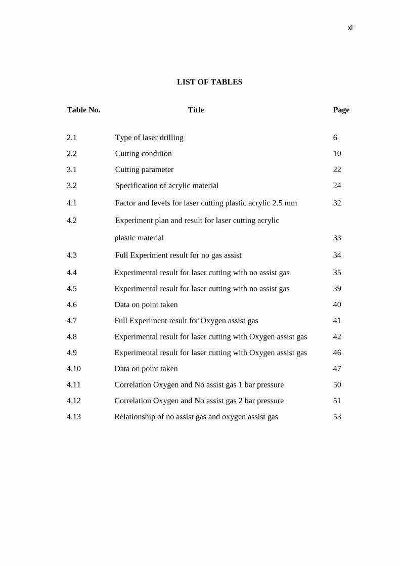
LIST OF TABLES
Table No. Title Page
2.1 Type of laser drilling 6
2.2 Cutting condition 10
3.1 Cutting parameter 22
3.2 Specification of acrylic material 24
4.1 Factor and levels for laser cutting plastic acrylic 2.5 mm 32
4.2 Experiment plan and result for laser cutting acrylic
plastic material 33
4.3 Full Experiment result for no gas assist 34
4.4 Experimental result for laser cutting with no assist gas 35
4.5 Experimental result for laser cutting with no assist gas 39
4.6 Data on point taken 40
4.7 Full Experiment result for Oxygen assist gas 41
4.8 Experimental result for laser cutting with Oxygen assist gas 42
4.9 Experimental result for laser cutting with Oxygen assist gas 46
4.10 Data on point taken 47
4.11 Correlation Oxygen and No assist gas 1 bar pressure 50
4.12 Correlation Oxygen and No assist gas 2 bar pressure 51
4.13 Relationship of no assist gas and oxygen assist gas 53

xii
LIST OF FIGURES
Figure No. Title Page
2.1 Drilling process 6
2.2 Laser marking process 7
2.3 Principle of a laser cutting system (schematic) 8
2.4 Ra graph 11
2.5 Schematic of typical beam profile 16
3.1 Flow chart of the methodology 19
3.2 Specimen for experiment 23
3.3 Laser cutting machine 25
3.4 Surfcom 130A Tester 26
3.5 Measurement taken print 27
3.6 Flow chart for analysis steps 28
3.7 Experimental flow chart 29
4.1 Specimen cutting position 35
4.2 1 bar gas pressure 36
4.3 2 bar gas pressure 37
4.4 Optimization Plot 38
4.5 Percent of Surface roughness, SR 39
4.6 Bar chart of surface roughness, Ra (µm) 40
4.7 Specimen cutting position 42
4.8 1 bar gas pressure 43
4.9 2 bar gas pressure 44
4.10 Fitted means for Ra 45
4.11 Percent of Surface roughness, SR 47
4.12 Bar chart of surface roughness, Ra (µm) 48

xiii
4.13 Ra comparison of no assist gas and oxygen
assist gas with 1 bar gas pressure 51
4.14 Ra comparison of no assist gas and oxygen
assist gas with 2 bar gas pressure. 52
xiv
LIST OF SYMBOLS
CO2 : Carbon Dioxide
Ra : Average surface roughness
Rz : Average maximum height
Rmax : Maximum roughness depth
µm : Micrometer
ns : Nano per second
K : Kelvin
C : Celsius
L : Length
kPa : KiloPascal
kW : KiloWatt
MPa : Mega Pascal
LCD : Liquid crystal display
% : Percent

xv
LIST OF ABBREVIATIONS
ANOVA : Analysis of variance
DOE : Design of experiment
CNC : Computer numerical control
FYP : Final Year Project
HAZ : Heat-affected zone
PCNC : Personal computer numerical control
Std. Err. : Standard error
UMP : University Malaysia Pahang
RSM : Response surface methodology
PVC : Polyvinyl chloride
CW : Continuous wave
NG : Non-gas
AD : Anderson-Darling
Vs : Versus
ASTM : American Society for Testing and Materials
Std. : Standard
1
CHAPTER 1
INTRODUCTION
1.1 ADVANTAGE OF LASER MACHINING
Laser cutting is an advanced machining process. It is material removal obtained
by focusing a highly intense laser beam on the workpiece (T. Thöniß, 2003). The laser
beam heat subsequently melts or vaporizes the workpiece throughout the thickness or
depth of the material thus creating the cutting front. A pressure assist gas jet used to
expel the molten material from the cutting front (Narendra B. Dahotre and Sandip P.
Harimkar, 2008). The assist gas also help in enhanced material removal through
chemical reactions such as oxidation of the material.
The specialties by using laser in mostly application nowadays are this process
technique more cheaper than other technique such as conversional process. By using
laser, the cutting edge has never dull. Besides, the laser cutting has be controlled by
computer programming so the accuracy of the cutting is more precise (Priyanka Kosta
Sonkushre, 2012).
Meanwhile, the equipment that mostly used in laser cutting is expensive. The
equipment of laser cutting are expensive but the product that has be produce by laser
cutting is more quality and make the whole cost has be cheaper (J.Stephen Spence,
2006). For example, the aspect of time cycle and the product produce. If the man uses
has be change to laser cutting method, we can save the cost for labor salary. Second, the
time taken for cutting by the laser is faster than labor. So, the we can increase the
production.
2
Third, by using laser cutting we can decreasing the mistake or waste raw
material such as usually happen if we used human. When the high price that we expand
for that can be balance by high income that we gain make the overall process cheaper
(J.Stephen Spence, 2006).
On the other hand, laser machining is a noncontact process. Laser cutting
process not need the workpiece to be clamp or centered on the precise fixture as in
conventional machining (EDM, water jet, ECM). Mostly the laser cutting use CNC-
controlled processes to giving accurate control over the dimensions of cut and faster
cutting speeds. Beside, laser cutting have high cutting speeds and fine precise cut
dimensions. Laser cutting have better quality of cut and its flexible process approaches
(Narendra B. Dahotre and Sandip P. Harimkar, 2008).
1.2 PROBLEM STATEMENT
The effect of assist gas on the surface roughness for Carbon Dioxide laser
cutting process.
1.3 PROJECT OBJECTIVE
There are two project objectives which are:
1. To study the effect of assist gas on the surface roughness on the finish
product.
2. To run experiment, collect and verify the data specimen.
3
1.4 PROJECT SCOPE
This study is focuses on four project scope.
i. To study the effect of assist gas on the interaction between the laser and
acrylic material.
ii. This study will uses CO2 laser cutting machine located in Manufacturing
Lab for gas assist which are Oxygen (O2), and Non-gas as the controller
parameter.
iii. The result will be analyzed by using Microsoft Excel and Minitab
software from that we can see the quality of cutting.
iv. Material used for this experiment is Acrylic sheet with thickness 2.5 mm
thickness.
1.5 ORGANIZATION OF THESIS
This thesis consists of five chapters. Chapter 1 presents introduction.
While Chapter 2 highlights on the literature review on article, journal and etc.
Chapter 3 explained the methodology for the project. Chapter 4 shows the result
from the experiment and the discussion regarding to the results. Finally, Chapter
5 concluded the project and provide with recommendation for the project.

4
CHAPTER 2
LITERATURE REVIEW
2.1 INTRODUCTION
In this chapter, the findings and previous studies regarding to this project title
will be presented. Most of the finding materials are based on book and published
journals. From the findings, the general informations about the project can be gathered
more easily before the experiment began. In section 2.2, the study and the finding of the
fundamental of laser cutting is explained. The types and parameters of the assist gas for
laser cutting machining had been told in section 2.3. Next, in section 2.4, the machining
process is discussed specifically. The laser cutting process then will be explaining in
section 2.5.
2.2 FUNDAMENTAL OF LASER CUTTING
The basic system build in laser cutting are laser projector, mirror, convex lens,
assist gas and tapering tip. For cutting steel material, assist gas or reactive gas such as
Oxygen are used to increasing the rate of cutting because the addition of the laser
energy be absorbed into the beam. Besides, assist gas flow also help to remove the
cutting waste on cutting area. Besides, to cut non-steel material such as ceramic, plastic
and wood we should used an inert gas flow to avoid any oxidation occur. For this case
all energy has be transmit into laser for cutting process (Noriah Bidin, 2002). The
advantage use laser for cutting steel is it can produce a narrow kerfs width than use
plasma arc. Kerf width is a thickness cutting rate occurs on material during cutting
process. Usually kerf width appear during cutting process on steel of sheet 9.5 mm is 1
mm.
5
Laser machine used the assistance of a computer to give the laser cutter
instruction of direction. The computer control will make the cutting processing more
accurate and consistent. The laser nears the material being cut from the side. The laser
beam concentrated onto one point the material to be cut so that the hole is made and
cutting can be continued (MaloyaLaser, March 1, 2010). The concentration of the laser
beam is 0.004 inch and laser take a large amount of energy to function. Laser cutting
can widely used to any material such as wood, steel, plastic, aluminum, foam, fabric,
paper leather, vinyl, film, rubber, acrylic, glass and ceramic (Gaynor Borade, 2000).
2.3 LASER MACHINING PROCESS
There is several machining process in this section such as drilling process,
marking process and cutting process. Each process show different method and
parameter used.
2.3.1 LASER DRILLING PROCESS
The application of laser drilling used in the aerospace, aircraft and automotive
industries. Laser drilling are non-contact process, precise, and effectively technique that
can be used to form small diameter (~100µm). The advantage of the laser drilling are it
can drill holes in difficult to machine material such as super alloys and ceramic (Voisey
and Clyne, 2004). The conventional mechanical drilling is slow process which is
drilling time (~60s/hole) compare to laser drilling process (100 holes/s). There are three
types of laser drilling which is single pulse, trepanning and percussion drilling. Table
2.1 on the next page present the type of laser drilling use in different condition.

6
Table 2.1: Types of laser drilling
Spec. Single pulse Trepanning Percussion drilling
Drilling narrow Less than 1 mm Less than 3 mm Less than 1.3 mm
Operating Single pulse Continuous wave Series of short pulse
Energy High High High
As show on Figure 2.1 below show the basic principle of laser drilling process
where the unfocused laser beam are projected to the focusing lens to increase laser
tendency.
Figure 2.1: Laser drilling process (Dr-Ing J.Berkmanns, 2008)
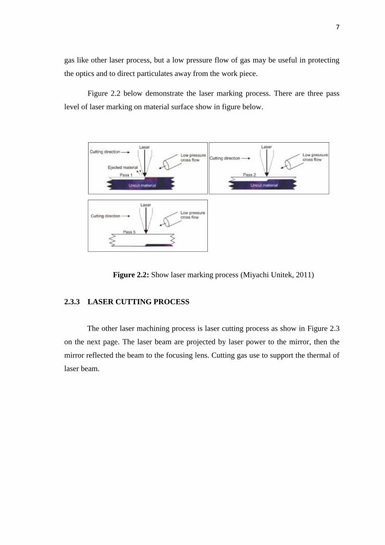
2.3.2 LASER MARKING PROCESS
Another type of laser machining is laser marking. Laser marking use the pulse to
cutting the material under 0.5 mm thickness (Jack Gabzdyl, 2007). It employ short pulse
with 20 or more watts of average power and the necessary pulse flexibility and shaping
option to optimize the cutting process. Laser marking also can used for drilling small
diameter holes. The high peak power of laser marking helps the laser energy to quickly
couple to the material while the long tail up to 200ns provides for deep penetration and
high material removal rates (Miyachi Unitek, 2011). This process does not need assist-
7
gas like other laser process, but a low pressure flow of gas may be useful in protecting
the optics and to direct particulates away from the work piece.
Figure 2.2 below demonstrate the laser marking process. There are three pass
level of laser marking on material surface show in figure below.
Figure 2.2: Show laser marking process (Miyachi Unitek, 2011)
2.3.3 LASER CUTTING PROCESS
The other laser machining process is laser cutting process as show in Figure 2.3
on the next page. The laser beam are projected by laser power to the mirror, then the
mirror reflected the beam to the focusing lens. Cutting gas use to support the thermal of
laser beam.

8
Figure 2.3: Principle of a laser cutting system (Dr.-Ing. M. Faerber, 2008)
The high intensity light beam quickly increasing the heat up the workpiece and
melt the material (Dr.-Ing. J. Berkmanns, June 18, 2008). The assist gas or cutting gas is
applied to remove the molten metal from the cut kerf and to cooling the focusing lens.
Two types of assist gas used be applied depending to the process. Cutting
process by oxygen assist gas, the material is easily burn and vaporized because the
reaction between the oxygen and the metal created additional energy which is supports
the cutting process (Brian Welz, 2012). Meanwhile, cutting process by nitrogen gas
(inert gas/non-reactive), the material is melt slowly. No additional heat generated but
the laser power required by nitrogen assist gas is higher than by using oxygen cutting
process. Besides, nitrogen gases can cut the material as clean cutting or high-pressure
cutting.
9
2.4 LASER CUTTING
In this section, the type of the assist gas and advantage of laser cutting process
has been discussed.
2.4.1 Type of the assist gas for laser cutting
There are four main approaches to cut the material using laser such as
evaporative laser cutting, fusion cutting, and reactive fusion cutting and controlled
technique. This technique depends on the condition of the material (Narendra B.
Dahotre and Sandip P. Harimkar, 2008). The main aspects that are focus on the material
condition are on the thermo-physical properties of the material, the thickness of the
workpiece and the type of the laser employed.
In evaporative laser cutting, the laser has provided the latent heat until the
material reaches the vaporization point and convert into vapor state. The quality of cut
is highly with clean edges because the material removal is due to direct phase change to
the vapor (Stephen Malkin and Changsheng Guo, 2008). This method is suitable for the
materials with low thermal conductivity and low heat of vaporization (organic material,
cloth, paper and polymers). Besides, in laser cutting they are moves relative to
workpiece and follow a straight or curved path.
The variation of fusion cutting use oxygen assisted in which reactive gas instead
of inert gas (Narendra B.Dahotre, 2008). In reactive fusion cutting, the heated is
projected to material in on point where an exothermic reaction with an oxidizing coaxial
gas jet is triggered another source of heat to the process. Due to combined effects of the
absorbed laser radiation and exothermic reaction, the molten layer reaches the
evaporation temperature thus facilitating the material removal by evaporation from the
surface (Sandip P. Harimkar, 2007). The dominant mechanism of material removal is
the oxidation of materials.
By the direct optical observations, the oxygen assist gas laser-cutting zone
which showed the temperature in the pale yellow band (~2000 K) as against the blue-
violet band (temperature higher than 2000 K) observed in evaporative laser cutting.
10
Higher cutting speeds are achieved in the oxygen-assisted cutting due to release of a
large amount of exothermic heat. However, to sustain the exothermic reaction during
laser cutting we must to deliver the sufficient amount of oxygen at high pressure
(O’Neill and Gabzdyl, 2000). The heat balance at the molten layer is given by setting
the heat gain by laser radiation and oxidation reaction equal to the heat losses by
conduction, melting, vaporization and ejection of liquid material by from the bottom
surface of the workpiece (Schuocker, 1986).
Besides assist gas laser cutting, there are several parameters we need to
understand the effect of the parameter over surface roughness such as gas pressure,
cutting speed and laser power (Mustafa Kurt, 2008). The method used to determine the
quality of surface roughness are well know that surface roughness effect fatigue life,
corrosion and friction and thermal conductivity of parts. The factors such as gas
pressure, cutting speed and laser power can affect the surface roughness of the parts.
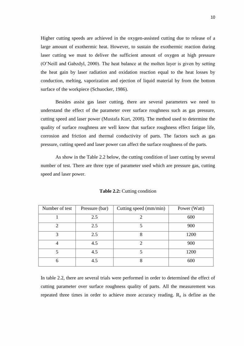
As show in the Table 2.2 below, the cutting condition of laser cutting by several
number of test. There are three type of parameter used which are pressure gas, cutting
speed and laser power.
Table 2.2: Cutting condition
Number of test Pressure (bar) Cutting speed (mm/min) Power (Watt)
1 2.5 2 600
2 2.5 5 900
3 2.5 8 1200
4 4.5 2 900
5 4.5 5 1200
6 4.5 8 600
In table 2.2, there are several trials were performed in order to determined the effect of
cutting parameter over surface roughness quality of parts. All the measurement was
repeated three times in order to achieve more accuracy reading. Ra is define as the
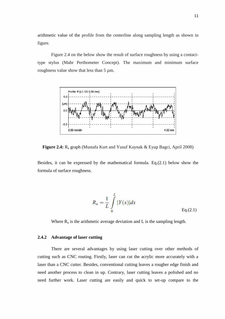
11
arithmetic value of the profile from the centerline along sampling length as shown in
figure.
Figure 2.4 on the below show the result of surface roughness by using a contact-
type stylus (Mahr Perthometer Concept). The maximum and minimum surface
roughness value show that less than 5 µm.
Figure 2.4: Ra graph (Mustafa Kurt and Yusuf Kaynak & Eyup Bagci, April 2008)
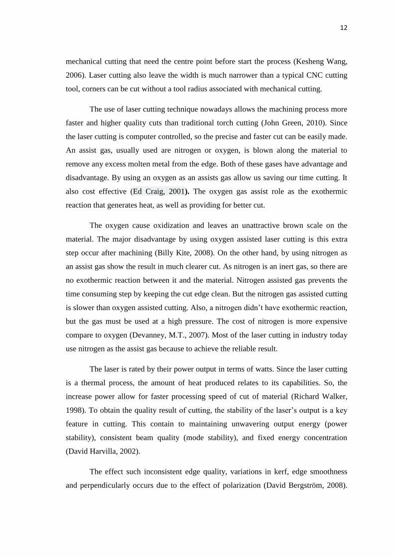
Besides, it can be expressed by the mathematical formula. Eq.(2.1) below show the
formula of surface roughness.
Eq.(2.1)
Where Ra is the arithmetic average deviation and L is the sampling length.
2.4.2 Advantage of laser cutting
There are several advantages by using laser cutting over other methods of
cutting such as CNC routing. Firstly, laser can cut the acrylic more accurately with a
laser than a CNC cutter. Besides, conventional cutting leaves a rougher edge finish and
need another process to clean in up. Contrary, laser cutting leaves a polished and no
need further work. Laser cutting are easily and quick to set-up compare to the
12
mechanical cutting that need the centre point before start the process (Kesheng Wang,
2006). Laser cutting also leave the width is much narrower than a typical CNC cutting
tool, corners can be cut without a tool radius associated with mechanical cutting.
The use of laser cutting technique nowadays allows the machining process more
faster and higher quality cuts than traditional torch cutting (John Green, 2010). Since
the laser cutting is computer controlled, so the precise and faster cut can be easily made.
An assist gas, usually used are nitrogen or oxygen, is blown along the material to
remove any excess molten metal from the edge. Both of these gases have advantage and
disadvantage. By using an oxygen as an assists gas allow us saving our time cutting. It
also cost effective (Ed Craig, 2001). The oxygen gas assist role as the exothermic
reaction that generates heat, as well as providing for better cut.
The oxygen cause oxidization and leaves an unattractive brown scale on the
material. The major disadvantage by using oxygen assisted laser cutting is this extra
step occur after machining (Billy Kite, 2008). On the other hand, by using nitrogen as
an assist gas show the result in much clearer cut. As nitrogen is an inert gas, so there are
no exothermic reaction between it and the material. Nitrogen assisted gas prevents the
time consuming step by keeping the cut edge clean. But the nitrogen gas assisted cutting
is slower than oxygen assisted cutting. Also, a nitrogen didn’t have exothermic reaction,
but the gas must be used at a high pressure. The cost of nitrogen is more expensive
compare to oxygen (Devanney, M.T., 2007). Most of the laser cutting in industry today
use nitrogen as the assist gas because to achieve the reliable result.
The laser is rated by their power output in terms of watts. Since the laser cutting
is a thermal process, the amount of heat produced relates to its capabilities. So, the
increase power allow for faster processing speed of cut of material (Richard Walker,
1998). To obtain the quality result of cutting, the stability of the laser’s output is a key
feature in cutting. This contain to maintaining unwavering output energy (power
stability), consistent beam quality (mode stability), and fixed energy concentration
(David Harvilla, 2002).
The effect such inconsistent edge quality, variations in kerf, edge smoothness
and perpendicularly occurs due to the effect of polarization (David Bergström, 2008).

13
This is cause of uncontrolled or random polarization processing. To overcome this
inconsistency, lasers must be same direction process. Laser cutting federates based on
the available laser power density and the properties of material to be cut. Cutting rates
are likewise inversely proportional to the materials density and thickness. Therefore,
feedrates will increase with additional a laser power, smaller the focused spot size laser
cutting, lower the required energy to initiate vaporization or material density (M.D.
Perry, 1999). Lastly, decreased the material thickness to increase the quality result.
The choice of the focusing lens has a great impact on the resulting cut quality of
the material. The focused spot size is proportional to the focal length, the power density
that is produces is proportional to the square of the length (Hansma and Paul K, 1996).
Short focal length lenses give very high energy densities, but are limited in their
application due to a shallow working depth. Longer focal length lenses have lower
power densities but are able to maintain those densities over a much broader range and
therefore can be used for thicker cross sections of materials given that they have enough
energy initially. The used of assist gas supplied to protect the lens and aid in the
material removal process. For most metal cutting applications, a reactive gas such as
oxygen can improve cutting speeds by 25% to 40% over the results obtained with use of
air (Shang-Liang Chen, 1996).
2.5 LASER CUTTING PARAMETERS
The experiments had been conducted by researchers with the different factors or
different variable. Some of them used the sheet metal as the material and few of them
used plastic sheet as the material. The results obtained are used to investigate the quality
of each factor as well the influencing on the observed quality characteristic.
The experiment on mild steel and stainless steel sheets (0.5 to 0.9 mm thick) in
using oxygen assist gas at constant pressure of 700 kPa, cutting speed (600-800 m/min)
and pulse width (0.2-0.9 ms) at constant values for each specimen (Kaebernick, 1999).
The kerf width increase slightly with increase in cutting speed up to critical value then
starts decreasing.