THE EARLY PHRYGIAN GATE AT GORDION, TURKEY: … Gate Report.pdf · the early phrygian gate at...
49
THE EARLY PHRYGIAN GATE AT GORDION, TURKEY: 2012 INVESTIGATION AND RECOMMENDATIONS FOR STRUCTURAL STRENGTHENING AND STABILIZATION Prepared for: Mr. Frank Matero University of Pennsylvania 115 Meyerson Hall 210 South 34th Street University of Pennsylvania Philadelphia, PA 19104 Prepared by: David T. Biggs, P.E., S.E. Biggs Consulting Engineering PLLC 740 Hoosick Road, Suite 4305 Troy, New York 12180 (518) 495-5739 October 2012 BCE Project 152-11
Transcript of THE EARLY PHRYGIAN GATE AT GORDION, TURKEY: … Gate Report.pdf · the early phrygian gate at...

THE EARLY PHRYGIAN GATE AT GORDION, TURKEY: 2012 INVESTIGATION AND RECOMMENDATIONS FOR STRUCTURAL STRENGTHENING AND STABILIZATION
Prepared for: Mr. Frank Matero
University of Pennsylvania 115 Meyerson Hall 210 South 34th Street University of Pennsylvania Philadelphia, PA 19104
Prepared by: David T. Biggs, P.E., S.E.
Biggs Consulting Engineering PLLC 740 Hoosick Road, Suite 4305 Troy, New York 12180 (518) 495-5739
October 2012 BCE Project 152-11

Page 2
TABLE OF CONTENTS PAGE DESCRIPTION, HISTORY AND BACKGROUND ...................................................................... 3
DESCRIPTION…………………………………………………………………………………...3 BRIEF HISTORY AND BACKGROUND……………………………………………………….5 SITE OBSERVATIONS AND COMMENTS ................................................................................ 7 SOUTH COURT WALLS ................................................................................................ 7 NORTH COURT WALLS .............................................................................................. 16 GENERAL OBSERVATIONS ....................................................................................... 22 ANALYSIS ............................................................................................................................... 27 SEISMIC CONDITIONS………………………………………………………………………………..29 COMMENTS AND CONCLUSIONS ......................................................................................... 33 RECOMMENDATIONS ............................................................................................................ 38 SUMMER SEASON 2012...…………………………………………………………………...38 LONG-TERM…… …………………………………………………………………………….39 REFERENCES…………………………………………………………………………………….…….43 APPENDIX A: SOUTH COURT - YEAR ONE REPAIRS.………………………………………….44 APPENDIX B: SOUTH COURT - YEAR THREE REPAIRS……………………………………….49

Page 3
DESCRIPTION, HISTORY AND BACKGROUND
DESCRIPTION The Early Phrygian Gate Walls were built in the 9th Century BC and have been described as the most monumental aspect remaining of the Early Phrygian Citadel at Gordion, Turkey (Goodman 2003). The gateway is created from the walls of the North and South Court buildings that flank a ramp leading into the interior of the citadel. Only portions of the stone walls that comprise the gateway remain. It is reported that the upper portions of the court buildings were mud brick, but none of that upper mud brick construction exists. In addition, several upper courses of Early Phrygian stone walls were likely removed as well prior to construction of the Middle Phrygian walls above. There are some remains of the Middle Phrygian walls that were constructed above the original gate walls. Previous reports describe the stone wall construction as rubble walls with roughly coursed limestone with rhyolite intermixed as the facing stones. The facing stones along the taller ramp walls are battered. The interior rubble core of the walls is composed of stone intermixed with earth. The walls vary in height based upon the grade. Figure 1 shows the North Court walls as viewed from the west during the 1955 excavation. The earthen filled, interior rubble core is clearly visible. Earthen mortar formed the joints of the facing stone along with chinking stones. Figure 1A is a blowup of the north wall of the South Court showing full earthen mortar bedding (arrow). The earthen mortar apparently was not consistently a full bedding mortar but was used to key in a mud plaster coating. Reportedly, the plaster coating had a lime wash (Young 1955). The foundations of the gate walls have never been exposed. A 1955 excavation was made at the southeast corner of the ramp that went 2.5 m (8.2 ft) below the wall's lowest ledge where groundwater was reported, but no foundation was observed (Rogers 1989). Additional excavations adjacent to the gate walls were only partial depth (Sams 1993). Based upon other walls in the complex, some have surmised that the gate walls may be founded on timbers. However, this has not been confirmed. In addition, there is rubble remaining from the Middle Phrygian period that is visible just east of the gate walls. Young 1955 describes the construction of the rubble as being formed in strips perpendicular to the east wall of the North Court. The rubble was to provide foundation support and enlarge the city gate eastward from its original location during the Middle Phrygian period.

Page 4
Figure 1 - North Court wall viewed from west
Figure 1A - South Court North wall
Inner face of North Court
Facing stones inside and out with earthen rubble in the middle.

Page 5
BRIEF HISTORY AND BACKGROUND
The gateway was excavated in 1955. Reports indicate the stone joints were "relatively tight and flat walls which still retained a considerable portion of original plaster at areas not directly exposed to weather" (Goodman 2003). Photographs from 1955 clearly show that both earthen mortar and plaster were generally intact following excavation (Figures 2 and 3).
Figure 2 - From 1955 Figure 3 - From 2012
In Figure 2, the plaster on the south face of the North Court walls is visible. Almost none of the plaster or the earthen mortar exists in Figure 3. Figure 4 shows a close up of the lower right corner of Figure 2 where the plaster and earthen mortar still exist. The majority of the mortar in the facing stones has been eroded.
Figure 4 - South east elevation of North Court wall (2012)

Page 6
In 1956, concrete capping was installed on the walls to prevent wall infiltration but it soon developed cracks and allowed water entry. The capping was replaced in 1988 (Goodman 2003 says 1989 but 1988 is scribed into the surface of the south wall capping). Subsequently, the continued erosion of the earthen mortar and fill within the rubble led to the development of a bulge in the facing stones about 1/3 below the top of the South Court's north wall (Figure 5). Goodman attributed this to "erosion of bedding mortar and destabilization of the thick inner core". I believe this is a correct diagnosis coupled with freeze-thaw effects.
Figure 5 - Bulge in north wall of South court wall
Monitoring efforts on the walls were subsequently developed by William Remsen and later Conor Powell and Richard Liebhart. In 1999, readings indicated the earthquake of August 16, 1999 increased the outward bulge approximately 30 to 40 mm (1.18 to 1.56 in.) (Goodman 1999). While there are remnants of monitoring equipment and scaffolding in place, the monitoring is not currently active. Results of wall monitoring from Professor Ahmet Turer (Turer 2010) were provided but no benchmark was provided and therefore the results are not particularly useful. The readings presumed all measured movement occurred in the South Court walls and was not verifiable. A proposal for stabilization of the gate walls was made in 1989 by Bernard Feilden who suggested structural grouting. Grouting was subsequently begun by Goodman in 2001 (test grouting) with partial wall grouting of the north wall of the South Court during the 2002, 2003, 2005 and 2006 seasons. More recent documents indicate that the grouting of the remaining areas of the South Court walls along with all of the North Court walls were halted to give further consideration of the stabilization technique. Additional wall monitoring was developed but not completed.

Page 7
SITE OBSERVATIONS AND COMMENTS
SOUTH COURT WALLS
1. Essentially, there is no visible earthen mortar or plaster remaining on the exposed facing stones. The lower portions of the north wall and east wall have been grout injected (Wong 2006) and those areas of walls have mortared or grouted joints. Figure 6 shows the north wall of the South Court. Figure 7 shows a close up of a portion of the wall from Figure 6 where the lower joints are filled from the previous grouting (lower arrow) and the upper joints are not filled (upper arrow).
No cracks were observed in the mortared/grouted joints.
Figure 6 - North wall of South Court Figure 7 - Close up of joints
2. There is a significant bulge on the north wall as seen in Figure 5. Recordings of
the bulge were begun in 1989. As previously noted, the bulge increased by 30 to 40 mm in 1999. Previously annual movements were less than 15 mm. During the earthquake, some stones came loose on the north wall (Goodman 2002). The stones are marked and being stored at the archeology depot for future reuse.
The bulge occurs above the grouted area of the wall. The joints are open (Figure
8); only chinking stones are visible in some joints. The literature has stated that this bulge has been a safety concern for many years. There is evidence the bulge increased following the 1999 earthquake. Given the open joints and the growing size of the bulge, the wall is a safety concern.

Page 8
Figure 8 - Joints in area of bulge
3. Two monitoring devices are attached to the wall (arrows, Figure 9). Reportedly,
they are no longer functioning. The devices are attached to individual stones; the stones are not mortared to adjacent stones. Any recordings might only indicate the movement of the individual stones.
Figure 9 - Monitoring devices

Page 9
4. The lower left of Figure 9 (oval) also shows a crack at the lower east corner below a ledge. This crack is in an area of wall that has been grout injected. A second ledge is lower and partially exposed.
Figures 10 and 11 show the crack following the 1955 excavation. Both ledges
are exposed. The crack is essentially unchanged between 1955 and 2012. This crack has been discussed in previous literature. Rogers 1989 mentions that
a repair method was proposed in 1987 by William C.S. Remsen that would pin the broken stones together. Figure 12 shows the current condition of the crack. While the corner was grout injected, apparently no pins were used to stitch the stones together as proposed by Remsen. However, no cracking of the grouted joints was observed in 2012.
Figure 10 - 1955 Photograph Figure 11 - 1955 Photograph

Page 10
Figure 12 - Southeast corner with mortared/grouted joints.
5. The east wall has cracks also. Figure 13 shows the crack locations compared to
the interior wall as shown by the red line on Figure 14. There is no direct correlation based upon the known information. The east wall shows no signs of global displacement due to the backfill. Cracking could be due to settlement, overload from upper walls, lateral pressure, or rubble fill settlement within the core.
Figure 13 - East wall of South Court

Page 11
Figure 14 - Plan of South Court
Figure 15 shows an overlay of the Middle Phrygian walls (dark black walls) over the early walls (grey walls). The red circle indicates there was another wall built over the area of the east wall cracks. Of all the possible causes, overload from the upper walls and some settlement are the most likely causes of the cracking.
Figure 15 - Overlay plan of Middle Phrygian
walls over Early Phrygian walls
6. The west end return wall of the north wall has large cracks and the stones are
displaced. Scaffolding and temporary bracing have been installed to retain loose stones (Figure 16). While some stones have already fallen, Figure 17 shows the temporary bracing that was installed to retain the remaining loose stones at the top; the bracing extends down approximately 8 feet from the top (arrow). There are more loose stones below the level of the bracing (oval, Figure 16). These loose stones can lead to partial collapse of the wall.
N

Page 12
There are large voids within the wall at the cracks. No earthen material is visible within the wall, only stones. Figure 18 shows a close up of the crack. Figure 19 is a photograph taken looking into the crack. Loose stone is visible but there is no earthen mortar; the mortar and plaster have been eroded.
Figure 16- West return wall Figure 17 - West return wall
Figure 18 - Crack at west return wall Figure 19 - Interior of crack
Figure 20 is a photograph from 1955. The west return wall is visible (box) and there is some cracking but little horizontal displacement that is visible in Figure 18.

Page 13
Figure 20 - 1955 photograph of west return wall.
7. Another bulge is developing at top of west end of the north wall (oval, Figure 21).
Figure 21 is taken adjacent to the inside corner of Figure 17.
Figure 21 - North Wall
8. Figure 22 shows the north wall. Several horizontal red lines and sloping green
lines have been added for reference to follow the stone coursing.
At first glance, the lower portion of the wall appears to have settled in the center (see the coursing relative to the green lines on Figure 22). However in the upper portion of the wall, the coursing appears nearly horizontal again. Thus, it appears that the sloped coursing at the bottom may be the way the wall was built.

Page 14
Figure 22 - Rectified photograph of North wall of South Court
9. Reportedly, the stone walls may be founded on timber logs. The literature states
that logs were found beneath many walls of the Terrace buildings and the Megarons. However, none of the reported excavations for the gate walls were extended beneath the gate walls. Thus, it is uncertain if there are or were logs used in the construction of the walls.
It is also assumed the foundations for the walls are not level but step up with the
grade. If logs were used in the foundation construction, the walls would have settled from the wood rotting. Based upon the horizontal joints in Figure 22, either there were no logs or the walls settled uniformly. Uniform settlement would be surprising for stepped foundations. More information is needed.
10. There is a concrete cap on the majority of the north wall of the South Court
(Figure 23). The cap was sectioned into panels and the joints have a sealant between them. The sealant is deteriorated in locations.
The cap slopes toward the west. At the end of the cap, there is a channel that has been created by erosion (arrow, Figure 23). Water entry causes erosion of the earthen mortar within the rubble core.

Page 15
Figure 23 - Cap above north wall of South Court.

Page 16
NORTH COURT WALLS
1. The south wall of the North Court has some earthen mortar and plaster remaining on the exposed facing stones (two ovals, Figure 24). There is no lime wash visible. There was no grout injection performed on the North Court walls.
2. There is a void at the bottom of the wall (lower arrow, Figure 24). Figure 25
shows that there was a void present following excavation in 1955. However, the void shown in Figure 25 is several courses below the one in Figure 24.
3. Figure 24 also shows a soft cap above the South Court walls. The mud bricks
that line the cap are weathering but the cap appears to be effective in preventing water infiltration. Reportedly, there is a hard cap beneath the soft cap.
4. The upper arrow in Figure 24 indicates a minor bulge. It is directly beneath the
upper wall. The 1955 photograph (Figure 25) does not indicate any bulge at that location.
Figure 26 shows the area of the bulge from the top (arrow). Based upon Figure
15, there was a Middle Phrygian wall that extended to the right in this f igure that may have caused a high point loading.
Figure 24 - South wall of North Court

Page 17
Figure 25 - 1955 photograph showing void at bottom of wall
Figure 26 - Top of wall
5. Figure 24 shows a diagonal crack at the left end of the wall. Figure 27 shows this
crack and the return wall (arrow). The joints of the return wall indicate some displacement has occurred.
Figure 28 shows the diagonal crack more clearly. There has been both lateral and outward displacement of the facing stones. The crack has weakened the corner and could collapse during a seismic event. The crack is not seen on the 1955 photograph of Figure 25.

Page 18
Figure 27 - Return wall and crack Figure 28 - Wall crack
The bottom of the crack (oval, Figure 28) indicates settlement has occurred.
Figure 29 is a close-up of the bottom of the crack. The settlement is likely due to overload, compression due to loss of earthen mortar, or foundation settlement. This settlement is also visible in the 1955 photograph of Figure 25.
Figure 29 - Bottom of crack
The angle of the crack is approximately 60 degrees from horizontal. The corner crack at the South Court in Figure 11 has the same angle. Both imply compression cracking.
6. The North Court's south wall has a return section and then the remainder of the
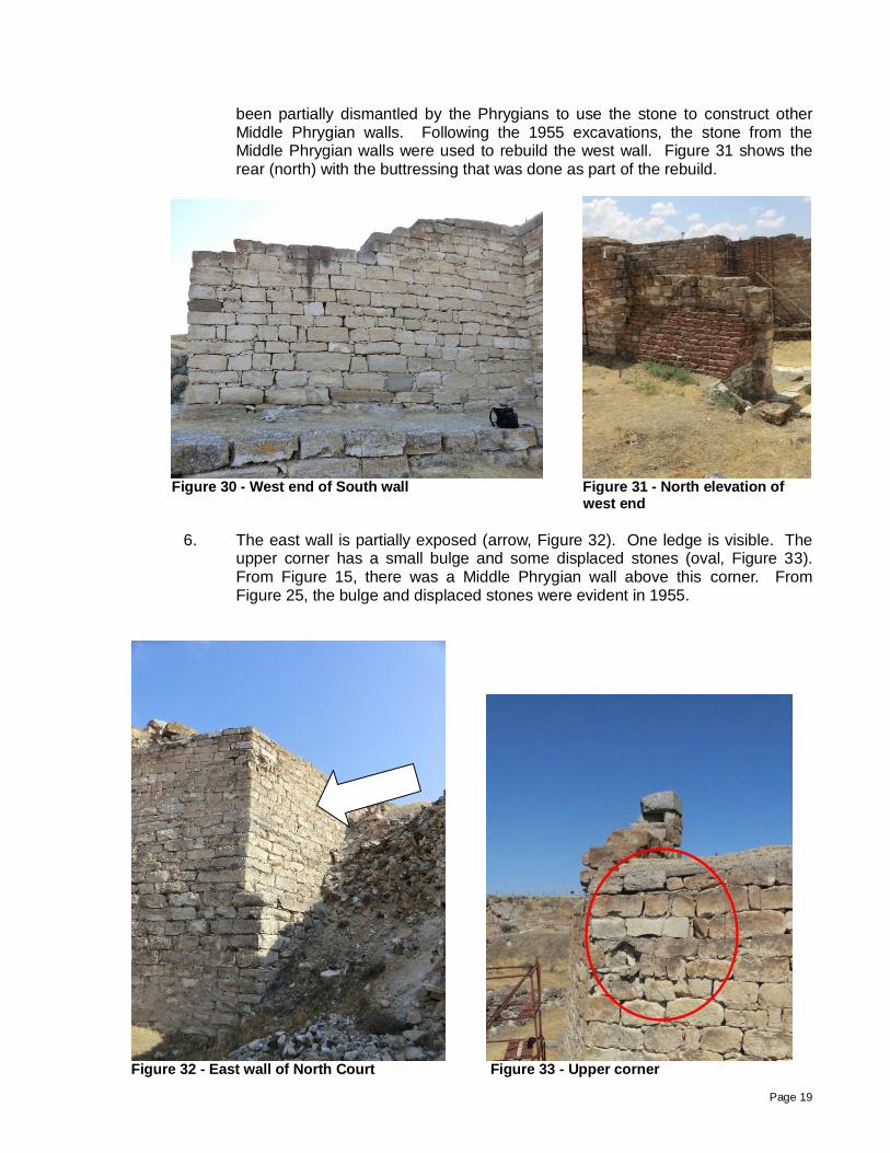
west wall. Figure 30 shows the south elevation. The west wall was partially rebuilt and buttressed (Keller 2009). Reportedly, this rebuilt section of wall had
Page 19
been partially dismantled by the Phrygians to use the stone to construct other Middle Phrygian walls. Following the 1955 excavations, the stone from the Middle Phrygian walls were used to rebuild the west wall. Figure 31 shows the rear (north) with the buttressing that was done as part of the rebuild.
Figure 30 - West end of South wall Figure 31 - North elevation of
west end
6. The east wall is partially exposed (arrow, Figure 32). One ledge is visible. The
upper corner has a small bulge and some displaced stones (oval, Figure 33). From Figure 15, there was a Middle Phrygian wall above this corner. From Figure 25, the bulge and displaced stones were evident in 1955.
Figure 32 - East wall of North Court Figure 33 - Upper corner

Page 20
Figure 34 is a view of the soft capping of the North Court walls; the South Court walls are beyond. The figure also shows the wall thickness is reduced to approximately 1.2m at the location of the bulge (oval, Figure 33 and Figure 32). Based upon Figure 15, this narrow corner once supported Middle Phrygian walls.
Figure 34 - Top of wall
7. Unlike the South Court, the North Court was partially excavated and the interior
walls are exposed (Figure 35). The east wall is denoted by the left arrow; the right arrow is the rear of the south wall that was shown in Figure 24. The low walls on the left are the remains of the north wall. The scaffolding was erected for work access.
Figure 35 - Interior walls of North Court with remnants of
Middle Phrygian walls above
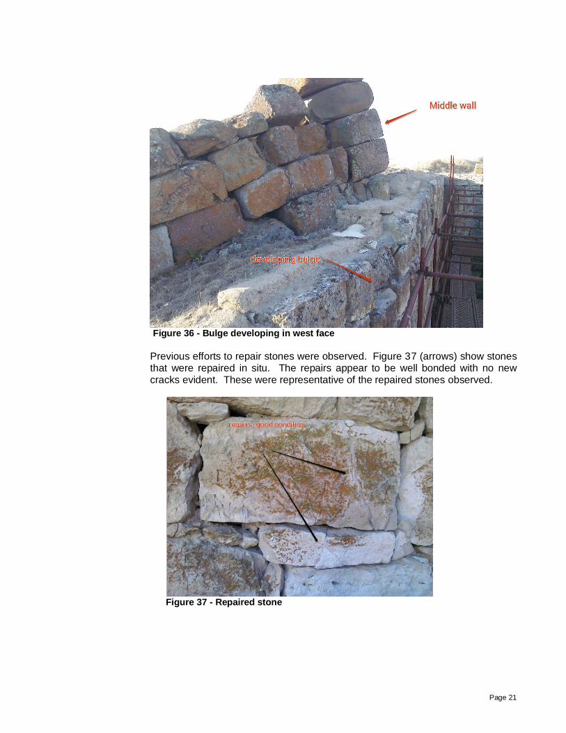
8. The east wall shows no signs of global displacement due to the backfill. There
are isolated bulges from facing stone movement. The bulges are primarily noticeable at the north end (Figure 36) adjacent to the upper walls.
Page 21
Figure 36 - Bulge developing in west face
Previous efforts to repair stones were observed. Figure 37 (arrows) show stones that were repaired in situ. The repairs appear to be well bonded with no new cracks evident. These were representative of the repaired stones observed.
Figure 37 - Repaired stone

Page 22
GENERAL OBSERVATIONS
1. Many of the stones are cracked. Keller 2009 describes the stone types and bonding, the possible inclusion of timber ties within the walls and as foundation support, the lime wash that was observed by Young, and the use of batter to stabilize the taller walls. None of the timber ties were visible.
2. Some stones have deteriorated faster than others. Figure 38 shows a stone that
has dissolved from environmental effects and erosion (upper arrow). The lower arrow points to a fractured stone. Figure 39 shows additional deteriorated stones.
Figure 38 - Deteriorated stones Figure 39 - Deteriorated stones
3. The Middle Phrygian backfill was installed systematically. There are indications
the rubble was constructed in "strips" and timber ties were used to stabilize each strip. Figure 40 shows the rubble just east of the gate walls. The existing angle of repose is approximately 45 degrees where the rubble has been partially excavated (arrows).
Figure 40 - Rubble Figure 41 - Rubble

Page 23
Figures 41 and 42 are close-up views of the rubble. Remains of timber were found in several locations (arrows, Figure 41 and Figure 42). The face of the rubble is nearly vertical at the sides of the strips (Figure 43). Figure 44 shows the 1955 excavation where the rubble is standing nearly vertical. The primary difference between 1955 and 2012 is that the earthen portion of the rubble has been eroded.
Figure 42 - Void from timber tie
Figure 43 - 2012 Photograph Figure 44 - 1955 Photograph
4. Earthen mortar and plaster are still visible in several locations. The material appeared identical for both the mortar and plaster. Four samples were taken of the earthen material for future testing and left with Elisa Del Bono.
Figure 45 shows a section of the north wall of the North Court where a sample was taken. In general, the plaster was still adhered to the stone and keyed to the earthen mortar. Figure 46 is a close-up of the plaster (arrow, Figure 45). In removing some of the plaster, the adhesion was better on the smoother stone on the right (limestone) in comparison to the stone with more surface texture on the left (rhyolite). This indicates that moisture absorption of the stone may be a better indicator of adhesion and should be evaluated.

Page 24
Figure 45 - North wall of North Court Figure 46 - Close of earthen mortar and
plaster
Figure 47 shows another wall area where the plaster is delaminating; there is a 10mm gap between the stone and the plaster. However, the surface strength of the plaster and the keying of the plaster with the mortar is still keeping the plaster on the wall. Future moisture and freeze-thaw effects will result in full delamination.
Figure 47 - Delaminated plaster
A small test was done on site. A sample of the plaster was wetted and the effects were observed for over an hour. Figure 48 shows a wetted area of mortar and plaster. Enough water was applied to cause some erosion. The wetted material felt silty and likely has clay. The dried trails of the material are visible in the lower portion of the figure. No such trails were found on the stone walls near existing mortar and plaster. The lack of dried mortar trails may indicate that water erosion is a slow process and wind abrasion or freeze-thaw effects may be the more likely failure mechanism for the deterioration of earthen plaster.

Page 25
Figure 48 - Wet test on mortar and plaster
Figure 49 shows a close-up of plaster. It was generally dense and firm. The surface had a skin coat of clay that seemed to be protecting it. This coating was dissolved silty material that had redried on the surface, much like the dried material visible in the test seen on Figure 48. Figure 50 shows earthen mortar under compression and still intact. The mortar is dense and firm.

Page 26
Figure 49 - Earthen plaster
Figure 50 - Earthen mortar

Page 27
ANALYSIS Figure 51 is an artist's rendering provided to me that could represent the Early Phrygian construction at the gate. The red line is the approximate height of the stone walls as they currently exist. The literature indicates that above the existing stone walls were additional stone courses, mud brick walls, a parapet and the roof construction.
Figure 51 - Artist's rendering of Early Phrygian gate (East Elevation)
The following assumptions were made: Stone weight: 163 pcf (based upon limestone) 2,611 kg/m3 Earthen material: 100 pcf (assumed dry) 1,602 kg/m3 Rubble core is 35% earth material: 141 pcf 2,259 kg/m3 Mud brick: 120 pcf 1,922 kg/m3 Roof construction: 25 psf over supported area (guess) 122 kg/m2
The weight and thickness of the earthen plaster were ignored. Based upon these assumptions, axial stresses in the wall were determined at various stages for the south wall of the North Court (arrow, Figure 51). This wall was measured as approximately 3m wide. The facing stones are approximately 0.8m thick. The wall is estimated to be approximately 9m tall although the exposed height is less. Stage 1 using the current height of the wall, assuming the earthen mortar is fully intact, and there is no load from the Middle Phrygian wall remnants. The calculated axial stresses are 27 psi (0.19 MPa). Stage 2 assuming the wall was as constructed in Figure 51 with an additional 5 ft (1.52 m) of stone wall was above the existing construction. On top of that was 15 ft (4.57 m) of mud brick walls, a parapet, and a roof tributary width of 20 feet (6.1 m). The calculated axial stresses are increased to 45 psi (0.31 MPa). Stage 3 assuming the current height of the wall with the Middle Phrygian wall built over top at seen in Figure 15. The assumption is the Middle Phrygian walls are 12 ft (3.7 m) thick and the same height as the construction in Figure 51. Up to 10 ft (3.0 m) of the gate cross wall is added as a point load to simulate that the original walls are stiffer as a foundation than the rubble and will attract more load.
North Court
South Court

Page 28
The calculated axial stresses in the original walls are between 80 psi and 293 psi (0.55 MPa and 2.0 MPa). While these are only approximations, the order of magnitude of the results are reasonable (less than 100 psi) and indicate the stone walls were adequately sized to support the assumed vertical loads. If the walls were founded on juniper logs, even the wood could support these stresses in cross-grain bearing if the wood is in good condition.

Page 29
SEISMIC CONDITIONS Turkey is a seismically active country with a major fault line along its northern border. The country is divided into five seismic zones from Zone 1 (highest) to Zone 5 (lowest). The Gordion region is in Zone 4 (Figure 52) which has relatively low seismicity. The seismicity of the Gordion region might be considered comparable to the east coast of the United States.
Figure 52 - Turkey's Seismicity
Doğan 2010 provided a map showing the location of various earthquakes (Figure 53). The Gordion area is marked with an oval. There have been very few earthquakes originating in the Gordion area, but many east and north within a couple hundred kilometers.
Gordion
Ephesus

Page 30
Figure 53 - Historical earthquakes in Turkey
According to the Republic of Turkey Prime Ministry, Disaster and Emergency Management Presidency, Earthquake Department, the two largest earthquakes recorded in nearby Polatli were 4.5M in both 1975 and 1983 (arrows, Figure 54). None of the literature provided reported damage at Gordion from these two earthquakes. However, no one may have been looking for damage at an excavation site.

Page 31
Figure 54 - Seismic activity near Polatli, Turkey
As previously noted, the Gordion site experienced seismic effects as a result of the 7.4 M, 1999 Izmit Earthquake. The 1999 epicenter was approximately 240 km away from Gordion (Figure 55).
Figure 55 - 1999 Izmit earthquake

Page 32
We have no recorded data of movement of the gate walls at Gordion due to the earthquakes in 1975 and 1983. The only data is related to the movement measured following the 1999 earthquake. There is no clear evidence that recent seismic activity has seriously damaged the walls. Further evaluation of the seismic effects on the walls is needed.

Page 33
COMMENTS AND CONCLUSIONS 1. Some of the cracking of the stone walls was evident in the 1955 photographs. The
cracking has become worse with the loss of the earthen mortar. Based upon preliminary calculations assuming uniform stone bedding, the vertical
stresses in the stone walls should not have been sufficient to cause cracking even with the weight of the Middle Phrygian walls above.
The partial bedding contact of the stones along with the loss of the partial earthen mortar
material in the joints accentuate the bearing conditions of the chinking stones. Once the partial bedding mortar is missing, the chinking stones become the primary support. These randomly placed chinking stones produce point loadings on the facing stones (arrows, Figure 56) that are eccentric. The point loading can cause stress concentrations that result in cracking and stone rotation.
Figure 56 - Point loading of stones
Another possible cause of cracking is due to stone deterioration. There are two types of stones and some have deteriorated worse than others. Stress in the stone from the loss of the earthen mortar accentuates this deterioration.
A third possible cause of stone cracking is the overall settlement of the walls. While there is no confirmation that the walls are founded on juniper logs, there is a strong likelihood based upon other findings. Even slight differential settlement causes further point loading and cracks the walls. These cracks would have occurred prior to 1955 excavation.

Page 34
2. There is no obvious evidence of overall stability issues with the walls. The walls of the South Court and the east and north walls of the North Court are backfilled with rubble from the Middle Phrygian period. That backfill imparts a lateral force on the walls which can be magnified by any seismic activity. However as stated later, the rubble fill appears relatively stable unto itself and the actual pressure developed by the rubble is unknown.
Another concern over stability is the possible presence of juniper logs under the walls. Their presence should be confirmed and their effect on the walls evaluated. To accurately assess the global stability of the walls, both the lateral pressures and the foundation conditions must be determined.
3. The shifting of the stones has produced the bulges. The shifting of the facing stones is primarily caused by seismic vibrations, freeze-thaw action, the loss of earthen mortar in the joints and the lack of cohesiveness of the rubble core in the walls. The loss of earthen mortar can place excessive stress on the chinking stones on the outside of the facing stones thereby causing a bulge. Based upon the photographic information from 1955, the bulges have developed since the walls were excavated and have continued to worsen with the loss of the earthen mortar.
The bulges appear to be the result of local movement of the facing stones and not the
overall (global) lateral movement of the walls. Replacing the earthen mortar in the joints of the facing stones and providing more uniform bedding are essential to removing the point loading and strengthening the walls.
4. The stabilization work performed to date appears to be performing successfully. This
work includes repairs to individual facing stones and grout injection of several walls. Success is described as the mortar has shown no visible evidence of deterioration, there is no evidence of cracking due to structural movement in the grouted areas of the walls, and no additional bulges have occurred in the grouted areas. Replacing the missing earthen mortar in the facing joints and providing more uniform bedding has been beneficial to the walls.
It is worth noting that the grout injection is not reversible. Grouting can always be added
but it can't be removed. Therefore before grouting more walls, it would be preferable to a) strengthen the walls without grouting, b) assess the wall performance through monitoring, then c) determine if more aggressive strengthening measures, including grouting, are necessary.
5. The grout stabilization process included a water-flushing of the core. While beneficial for
grout consolidation, this process removes the earthen binder of the rubble and further destabilizes the rubble core until the grout injection is completed in that section of the wall.
The grout injection of the South Court's north wall was stopped without finishing the
grouting full height. The wall is now vulnerable to seismic effects due to differential stiffness. The ungrouted area above the grouted portion does not have the same strength or stiffness as the grouted portion and will respond differently during seismic activity. It would be beneficial to complete the grouting.
The modern grout material is stronger and stiffer than the earthen material it replaces.
Testing should be performed to characterize the earthen material and the strength of the modern mortar and grout adjusted to be as similar as possible.
Page 35
For walls areas that have received no grout injection, filling only the facing stone joints would be a beneficial first step. After that, the walls could be monitored for a period of time before deciding whether a grouting campaign is needed or another method such as removing the rubble backfill to relieve lateral earth pressure would be beneficial.
6. Keeping moisture out of the walls is essential to avoiding their deterioration. Water causes erosion of the earthen material in the rubble core and facing stones. In addition, trapped moisture can produce expansive freeze-thaw effects on the walls that may cause them to spread or bulge.
The walls originally had earthen joints with an earthen plaster coating and lime wash to prevent through wall moisture entry. The majority of the plaster is gone and the earthen mortar is mostly gone as well. The joints of the facing stones are currently open and provide minimal moisture protection.
In addition, the walls originally had a roof to provide a protective cover. Currently, the soft capping for the walls is limiting water infiltration through the top. The capping must be maintained. Unfortunately, there was damage done to the walls from water infiltration prior to the capping being installed. The east walls of both courts and the partial north wall of the North Court are backfilled. The only protection from water infiltration through the back side is due to any residual earthen plaster. A study of the water infiltration from the backfilled sides along with a recommendation to remove the rubble backfill, provide drainage away from the walls, or waterproof the back side of the walls should be undertaken.
7. Turkey is very seismically active. However, records indicate that the Gordion region has not had a major earthquake in the immediate area.
While there have been relatively few earthquakes originating in the region, there has been seismic shaking from distance earthquakes. The 1999 earthquake was one of the worst in Turkey's history but was distant enough that the shaking in Gordion did not affect most of the walls. From the reports provided, only the south wall of the North Court had measurable movement at the bulge. This limited movement is surprising in that the rubble east of the gates appears to be in a more unstable condition without any facing stones to protect the rubble. It is likely that the seismic movement at the bulge of the South Court occurred due to the weakened state of the walls from the loss of the earthen mortar in the facing stones and the wash out of the earthen material in the rubble core.
It appears the walls are susceptible to "seismic fatigue" or repetitions of low seismic
energy caused by minor local earthquakes or the effects of major distant earthquakes. Thus it will not be necessary for a major earthquake to collapse the walls. The combination of minor earthquakes locally and the effects of distant larger earthquakes will continue to damage the walls unless they are strengthened.
There are two viable options for strengthening. One option is to provide external
bracing. Figures 57 and 58 show historic two structures in Turkey that were provided with external bracing. In Figure 57, the bracing is for a building façade in Istanbul; except for the façade, the building has been demolished. The bracing prevents the façade from falling into the street and protects pedestrians and motorists passing by.

Page 36
The bracing in Figure 58 is for the Temple of Augustus and Rome in Ankara. The site is adjacent to an active mosque and receives many visors and tourists daily.
In both cases, the sites in Istanbul and Ankara receive a lot of pedestrian traffic; safety is a key concern. The aesthetics of the construction are compromised by the bracing for safety's sake.
Figure 57 - Building façade bracing Figure 58 - Monument bracing
The second option is to return the walls to their original strength or better. In this option, the aesthetics are retained but the strengthening is a function of the original construction. Figures 59 and 60 show two Roman the historic monuments at ancient Ephesus in Turkey. Figure 59 is the library and Figure 69 is the coliseum. The library was reconstructed without external bracing and the coliseum is undergoing a partial reconstruction and strengthening. Ephesus is in Seismic Zone 1 (the highest possible level in Turkey, Figure 52) and has experienced numerous earthquakes (Figure 53). Neither uses external bracing and each receives numerous tourists daily.
Figure 59 - Library at Ephesus Figure 60 - Coliseum at Ephesus
A major earthquake is more likely to strike the Ephesus region rather than Gordion. The
likelihood of major damage or collapse in Ephesus is high. However, both sites were strengthened and reconstructed without adding external bracing
Given the low number of tourists that visit Gordion relative to Ephesus and the lower
seismic risk in the Gordion area, the strengthening option is more reasonable than

Page 37
external bracing. Based upon performance of the walls from 1955 until now, strengthening at Gordion may resist the expected seismic effects. Internal strengthening will also maintain the integrity of the heritage structure and not change the aesthetics.
Strengthening would involve replacing the missing earthen mortar and providing full
bedding to the facing stones. However rather than using earth again, a lime mortar would be used. The goal would be to use a material that is closest to the earthen mortar in compressive strength and stiffness. This may require testing of the materials.
8. The Middle Phrygian rubble fill east of the gate walls appears very tenuous as though it
could collapse at any time. However, the rubble has been in a generally stable condition since being exposed despite having no facing stones. The angle of repose for the sides of the rubble strips is approximately 90 degrees (Figures 43 and 44). Since the earthen material continues to erode and the timber ties are no longer present in the strips, the outermost strip is weaker than was originally constructed. These facts imply that a partial collapse is possible, but that a collapse would likely be limited to one strip at a time. Buttressing of the exposed rubble strip would likely provide the needed stabilization.
The angle of repose for the excavated ends of the strips is approximately 45 degrees (Figure 40). 1955 photographs indicate this material has been relatively unchanged since being exposed. Additional collapse of the excavated ends is unlikely and poses little risk.

Page 38
RECOMMENDATIONS
SUMMER SEASON 2012
While at the site, I made several recommendations and met with Elisa Del Bono and Angelo at the site and later reviewed my findings with Brian Rose. I recommended some minor work be completed in 2012 if time and resources allowed it.
2012-1: Add more bracing to the west return wall of the north wall of the South Court. There is already staging with vertical bracing to retain the loose and missing facing stones at the west return wall. Since the area with loose stones has enlarged since the bracing was installed, I recommended extending the existing bracing more to the outside corner and lower on the wall. In addition, I recommended adding bracing to the north wall at the bulge adjacent to the inside corner. No additional staging is needed.
2012-2: Replace the deteriorated sealant at the concrete cap joints over the South
Court walls. Any splits or missing sealant should be replaced. 2012-3: Infill the opening in the top of the South Court wall to prevent further
erosion. The opening is visible in Figure 23. The infill can be earth and clay.
2012-4: Retrieve earthen mortar and plaster samples for future evaluation. With
the approval of the Site representative, samples were taken on July 9, 2012. Later that day, new directions came from Turkish authorities that samples were no longer allowed to be taken out of the country for testing. Therefore, the samples were left with Elisa Del Bono after I left in hopes the samples could be shipped to the United States in the future.
Page 39
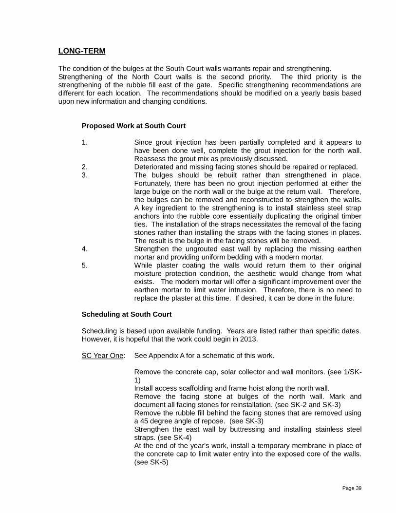
LONG-TERM The condition of the bulges at the South Court walls warrants repair and strengthening. Strengthening of the North Court walls is the second priority. The third priority is the strengthening of the rubble fill east of the gate. Specific strengthening recommendations are different for each location. The recommendations should be modified on a yearly basis based upon new information and changing conditions.
Proposed Work at South Court
1. Since grout injection has been partially completed and it appears to
have been done well, complete the grout injection for the north wall. Reassess the grout mix as previously discussed.
2. Deteriorated and missing facing stones should be repaired or replaced. 3. The bulges should be rebuilt rather than strengthened in place.
Fortunately, there has been no grout injection performed at either the large bulge on the north wall or the bulge at the return wall. Therefore, the bulges can be removed and reconstructed to strengthen the walls. A key ingredient to the strengthening is to install stainless steel strap anchors into the rubble core essentially duplicating the original timber ties. The installation of the straps necessitates the removal of the facing stones rather than installing the straps with the facing stones in places. The result is the bulge in the facing stones will be removed.
4. Strengthen the ungrouted east wall by replacing the missing earthen mortar and providing uniform bedding with a modern mortar.
5. While plaster coating the walls would return them to their original moisture protection condition, the aesthetic would change from what exists. The modern mortar will offer a significant improvement over the earthen mortar to limit water intrusion. Therefore, there is no need to replace the plaster at this time. If desired, it can be done in the future.
Scheduling at South Court
Scheduling is based upon available funding. Years are listed rather than specific dates. However, it is hopeful that the work could begin in 2013.
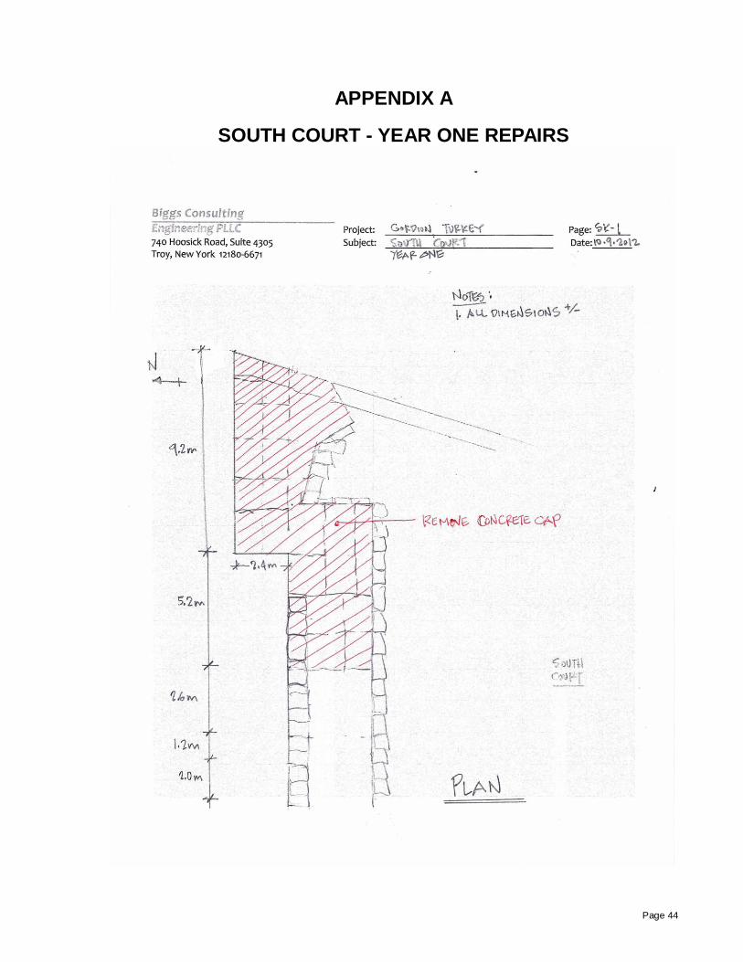
SC Year One: See Appendix A for a schematic of this work.
Remove the concrete cap, solar collector and wall monitors. (see 1/SK-1)
Install access scaffolding and frame hoist along the north wall. Remove the facing stone at bulges of the north wall. Mark and
document all facing stones for reinstallation. (see SK-2 and SK-3) Remove the rubble fill behind the facing stones that are removed using
a 45 degree angle of repose. (see SK-3) Strengthen the east wall by buttressing and installing stainless steel
straps. (see SK-4) At the end of the year's work, install a temporary membrane in place of
the concrete cap to limit water entry into the exposed core of the walls. (see SK-5)

Page 40
SC Year Two: Remove the temporary membrane cover. Mortar fill the joints of the facing stones of the east and north walls that
were not removed as part of the bulge rebuilding. Install monitors to determine if future grouting is required.
Grout fill the lower portions of the exposed rubble fill. Reassess the grout mix to determine a mix with strength closer to the earthen material.
Repair broken facing stones that were removed or replace deteriorated stones with newer stones. Pin and patch techniques have already been developed to repair stones that are sound but broken.
Reinstall the temporary membrane at the end the year's work. SC Year Three: See Appendix B for a schematic of this work.
Remove the temporary membrane cover. Rebuild the rubble core and the facing stones using mortar. Install stainless steel straps to strengthen the facing stones and bond
the facing stones to the rubble core. Reinstall the temporary membrane at the end the year's work. SC Year Four: Remove the temporary membrane cover. Install a new soft cap. This cap should be provided over both the north
and east walls using details and procedures already developed. Save the temporary membrane at the end the year's work.

Page 41
Proposed Work at North Court
1. Since there has been no grout injection of these walls, the
recommendation is to strengthen the facing stones by replacing the missing earthen mortar with a modern mortar.
2. Rebuild the small bulges at the tops of the walls. 3. Deteriorated and missing facing stones should be repaired or replaced. 4. Strengthen the large crack adjacent to the west return wall. Scheduling at North Court Again, scheduling is based upon available funding. Years are listed rather than specific dates. These recommendations include: NC Year One: Rebuilding minor bulges at the tops of the walls. Replace missing stones. Mortar fill the joints of the facing stones. Strengthen the crack at the return wall. This could include mortaring the
joints and installing steel reinforcement in the joints. Details are to be determined after the results of the South Court are evaluated.
NC Year Two: Rebuilding
On-going Maintenance - Every Year The soft capping and drainage improvements that have been made appear to be functioning but the mud brick liners are weathering. On-going maintenance should be performed on a yearly basis to maintain the soft capping.
Page 42
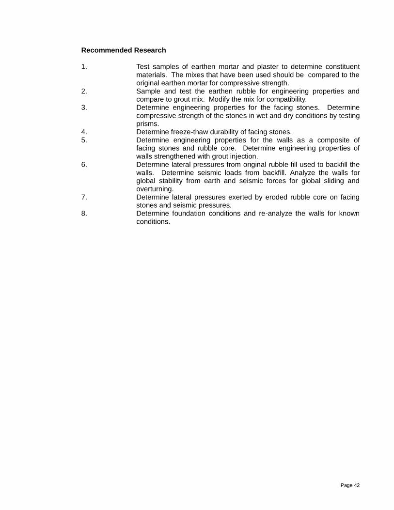
Recommended Research
1. Test samples of earthen mortar and plaster to determine constituent
materials. The mixes that have been used should be compared to the original earthen mortar for compressive strength.
2. Sample and test the earthen rubble for engineering properties and compare to grout mix. Modify the mix for compatibility.
3. Determine engineering properties for the facing stones. Determine compressive strength of the stones in wet and dry conditions by testing prisms.
4. Determine freeze-thaw durability of facing stones. 5. Determine engineering properties for the walls as a composite of
facing stones and rubble core. Determine engineering properties of walls strengthened with grout injection.
6. Determine lateral pressures from original rubble fill used to backfill the walls. Determine seismic loads from backfill. Analyze the walls for global stability from earth and seismic forces for global sliding and overturning.
7. Determine lateral pressures exerted by eroded rubble core on facing stones and seismic pressures.
8. Determine foundation conditions and re-analyze the walls for known conditions.

Page 43
REFERENCES Doğan 2010, Doğan, M., Earthquake Education In Civil Engineering Departments Of Universities Of Turkey, European Journal of Educational Studies 2(1), 2010
Goodman 1999, Goodman, Mark M., Architectural Conservation at Gordion: Summer 1999,
Gordion Excavation Project, University of Pennsylvania, 1999 Goodman 2002, Site preservation at Gordion, an Iron Age city in Anatolia, Conservation and Management of Archeological Sites, pp. 195-214, Volume 5, Number 4, 2002 Goodman 2003, Goodman, Mark M., Site Conversation at Gordion: Summer 2003, Gordion Excavation Project, University of Pennsylvania, 2003 Keller 2009, Keller, Meredith A., The Early Phrygian Gate At Gordion, Turkey: An Investigation Of Dry Stone Masonry In Seismic Regions And Recommendations For Stabilization, Thesis, Graduate Program in Historic Preservation, University of Pennsylvania, 2009 Rogers 1989, Rogers, Mark. H., Site Conservation at Phrygian Gordion, Honors Essay, Department of Art, University of North Carolina, 1989 Sams 1993, Sams, G. Kenneth, Gordion 1992, XV. Kazi Sonuclari, Toplantisi, May 1993 Turer 2010, Turer, Ahmet, emails and data, Middle East Technical University, April 2010 Wong 2006, Wong, Kelly H., Early Phrygian Citadel Gate 2006 Treatment Report, Architectural Site Conservation at Gordion, Turkey, University of Pennsylvania, 2006 Young 1955, Young, Rodney. S., The Campaign of 1955 at Gordion: Preliminary Report, American Journal of Archaeology, Vol. 60, No. 3. (Jul., 1956), pp. 249-266
Page 44
APPENDIX A
SOUTH COURT - YEAR ONE REPAIRS

Page 45

Page 46

Page 47

Page 48

Page 49
APPENDIX B SOUTH COURT - YEAR THREE REPAIRS