The Dynamic Stress-Strain Relation of Metals as · The Dynamic Stress-Strain Relation of Metals as...
57
The Dynamic Stress-Strain Relation of Metals as Determined from Impact Tests with a Hard Ball by C. R. Mok and J. Duffy Technical Report No. Nonr-562(20)/ Division of Engineering Brown University Providence, R. I. 02912 June, 1964 Sponsored by Dept. of the Navy Office of Naval Research Under Contract Nonr-562(20)37 Rg•st Available Copy Task Order NR-064-424
Transcript of The Dynamic Stress-Strain Relation of Metals as · The Dynamic Stress-Strain Relation of Metals as...

The Dynamic Stress-Strain Relation of Metals as
Determined from Impact Tests with a Hard Ball
by
C. R. Mok and J. Duffy
Technical Report No. Nonr-562(20)/Division of Engineering
Brown UniversityProvidence, R. I. 02912
June, 1964
Sponsored by Dept. of the NavyOffice of Naval Research
Under Contract Nonr-562(20)37Rg•st Available Copy Task Order NR-064-424
. . ft
ACKNOWLEDGMENTS
The helpful discussions with Professor D. C. Drucker,
Professur H. Kolsky and Professor P. S. Symonds are greatly appreciated
Thanks are also due to Messrs. R. Pagliarini, P. Rush and
R. R. Stanton for their assistance in the experimental work and to
Mrs. J. Alexander and Mr. A. Abols for p.'eparing the manuscript mid figures.

rhe Dynamic Stress-Strain Relation of Metals as
Determined from Impact Tests with a Hard Ball
by
C-H. Mok and J. Duffy
Abstract
An anilysis is presented of the impact process occuring when a
hard ball strikes the surface of a large metal specimen, It is shown that
the results of dynamic indentation tests can be interpreted to provide a
measure of the yield stress of the metal over a range of strains taking into
account the influence of strain-rate. Experiments are described in which
steel balls are allowed to drop onto specimens of lead, steel and aluminum.
In each test the velocities of impact and rebound are measured as well as
the !iameter of the indentation remaining in the metal specimen and the time
of contact Letween specimen and indenter. These experimental results are
used in conjunction with the analysis to provide for each metal a dynamic
stress-strain curve which is then compared to results of a simple compression
test performed under impact conditions. For all metals the best agreement
1,500 sec 1. Finally, the present analysis provides a model of the indentation
process whizh furnishes quitq accurate predictions of the size of the permanent
indentation, the time of contact during impact and the coefficient of
restitution, if the dynamic stress-strain relation of the material is known.
The results in this paper were obtained in the course ofresear,'h sponsored by the Office of Naval Research underContract Nonr-562(20) with Brown University
** Respectively Research Assistant and Associate Professor,Division of Engineering, Brown University, Providence, R. I.
-2-
1. :introduction.
In one of the simplest of dynamic tests a small but hard indenter
falls under the action of gravity onto a massive specimen. It is an easy
matter, in general, to measure the velocities of impact and of rebound and the
size of the remaining indentation in the specimen. In the past this test has
received considerable attention from numerous investigators [1- 1]* Unfortu-
nately, there is no completely satisfactory analysis of the elastic-plastic
problem so that it is extremely difficult to use this indentation test as a
meanz of determining material properties. Martel [5) suggested that the yield
pressure be treated as constant from the start to the end of impact, and
Tabor's work [1) is based lirgely on thi3 assumption for which there is
experimental evidet~ce in the work of Crook [6] and of Tabor himself. The
recent work of Goldsmith et al. [7 and 8] as well as the results of a previous
paper [9] seem to indicate that the traditional concept of a constant yield
pressure during impact is not adequate. Furthermore, this concept is no't
consistent with the results obtained in dynamic tests of an entirely different
nature performed by other investigators. The present investigation is intended
to examine the feasibility of using a simple impact test to determine the
dependence of yield stress on strain and on strain-rate.
To achieve this aim, it is necessary first that an expression be e3ta:)-
lLshed for the yield pressure existing underneath the ball and that, in turn,
yield pressure be related to yield stress. Secondly, it is necessary that the
strain and the strain-rate be evaluated using the diameter of the permanent
indentation in the specimen and the time of contact during impact. Tabor and
Martel have given expressions for the yield pressure in terms of measurable
quantities [1]. However, in deriving both of these expressions the yield
pressure is taken as constant, whereas to investigate the dependence of yield
*Numbers in square brackets refer to the Bibliography.

- 3-
stress on strain and on strain-rate, work-hardening must be taken into ac-
count. Therefore, a new expression for yield pressure is needed, Equation (7).
It is derived using conservation of energy and an empirical power relation be-
tween impact velocity and indentation diameter. Such a power relation appar-
ently holds very closely for a number of metals and alloys over a wide range of
temperatures [9 and 10]. Finally, the yield stress and the yield strain are
found using the empirical formulae
a= P/c (1)
E = d/5D (2)
first proposed by Tabor and in which where c is a constant near to 2.8 and a
is the true stress and e the true strain. These formulae are based on a
comparison of the results of static indentation tests and simple compression
tests. It is felt they can be applied in the present experiments because, as
explained below, the impact velocities are not so high that inertia effects
beco'ne important.
It is comforting to know that the expression for yield
pressure mentioned above and presented in Equation (7) can be derived in a
completely different manner by taking for the relation between stress and
strain in the specimen an expression of the type a a bcn , Finally, by
combining this with Newton's second law, an expression is obtained containing
the parameters b and n which predicts quite accurately the size of the
permanent indentation in the metal specimen.
The results of the analysis were examined by porforming impact tests
with steel balls on four different metals and plotting the computed yield
stress against strain. For compari3on a series of dynamic tests in simplo
compression were miade on the same metals keeping the strain-rate 39 nearly
-4-
constant as possible in each test. The two sets of results compare favorably,
indicating that within the limit. of the present experiments the dynamic yield
stress of metals can be measured in impact tests w4 .t.- a hard ball. The result.
also show that the yield stress of lead ard of steel depend more strongly on
strain-rate than tbht of the aluminum alloys tested.
NI. Analysis of the Indentation Process under Impact
The impact velocity in the present tests is sufficiently low so that
for purposes of analysis the impact process can be taken as quasi-static. ",
means that within and in the neighborhood of the indentation the strain distri
bution (although not the strain magnitude) is independent of impact .Vlocit,
There is considerable evidence to suggest that this gives a good description c
impact within the range of present velocities, 1 cm/sec-600 cm/sec.(See Gold-
smith et al. [8] and Hunter [11].)
One can simplify the problem further, in view of the pronounced plast"
flow during impact, by neglecting the initial elastic stage and thus considerit
only a two-stage impact process in which the initial plastic work-hardening
is followed by an elastic recovery once the whole forward energy of the inden-
ting ball has been consumed. In this it is presumed that the ball itself
undergoes no plastic dero.mation at any stage during impact. It is true, as
pointed out by K. L. Johnson [12), that pla2tic effects are present in the
specimen during recovery but these are neglected in the analysis. There
remains still the question of the influence of strain-rate on the material
properties of the specimen. Obviously, the strain-rate changes during each
impact test starting at a value which probably depends on the initial velocity
of the ball and going down to zero. It is most likely also that the strain-
rate varies from test to test. However, for the present analysis each impact
is pzvesumed to have one characteristic or ave.age strain-rate. This is clearly
- 5-
a strong simplification, but it is a necessary one until a better analysis
of the strain distribution is available. The justification for adopting this
simplification depends in part on the resul... As will be seen, the present
analysis when applied to test results, leads t. dynamic stress-strain curves
corresponding to a constant strain-rate which are in good agreement with those
of other investigators.
(1) Plastic Strain-Hardening Stage
Impact is presumed to start with a plastic strain-hardening stage in
which the motion of the ball is resisted by the specimen material with a
pressure dependent on it- work-hardening properties. The expression for yield
pressure is derived from impact test results and using conservation of energy.
It is shown later that this derivation is equivalent to making use of a stress-
strain relation of the type a = bcn for the plastic loading stage.
After the ball strikes the specimen, the rate if loss of kinetic energy
T which it suffers must at each instant equal the rate of work of the inden-
ting force, to a close enough approximation. If x is the approach of the
two bodies, then
(Pwa2 /4) 8x z 6T
whore a is the diameter of the indentation at a given x . For a spherical
ball striking a plane surface
6a/6x = 2D/a (4)
where D is the ball diameter. In writing this expression, it is presumed
that the indenting ball is hard and that there is not too much "piling-up" or
"sinking-in" near the contact area. Combining Equations (3) and (4) gives
P = (8D/wa 3 )(6T/6a) (5)
for the yield pressure. It remains to evaluate 6T/6a
-6-
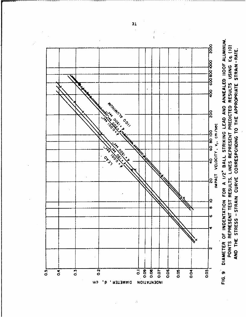
Previous results indicate that the diameter of the permanent indenta-1/ciwer
tion d produced by impact at a velocity v1 is proportional to v1 where
a is a constant [9]. This relation holds quite closely for the two materials
tested with a lying between 0.44 and 0.47 irrespective of temperature (see
also Figures 9 and 10). Hence, the energy W lost to deformation must be
proportional to d 2/. If, furthermre, the indentation process occurs quasi-
statically and if the rtrain-rate Aoes not influence strongly the relation be-
tween load and deflection, then the energy lost at any stage of impact will
depend only on the depth of penetration. This means that throughout the impact
process W is proportional to a 2/a, so that 6W/6a = 2W/ca . Applying the
principle of the conservation of energy SW = 6T so that
P= (l ) W/(wa 4/32D) (6)
at any stage of impact. The maximum value of P occurs when a becomes equal
to d and is given by
P 112 '411)mvl)/(wd /32D) (7)
This is the expression for the yield pressure used in the present investigation.
It may be compared to
(P) /(.d7/A2D) (8)
derived by Martel and
(P) a (1-.0e2)X v12)/(wd 4/32D) (9)
derived by Tabor, in iahich e is the coefficient of restitution. The only
difference between Equatiai (7) and Equations (8) and (9) is that (7) takes into
account the work-hardening properties of the material where (8) and (9) are
derived for a constant yield pressure. (P)M must be greater than (P)T and
experimental results indicate that, in general, P is greater than (P), '
- 7-
As mentioned above, an alternativa derivation is available leading
again to the expression for the yield pressure in Equation (7). This deriva-
tion makes use of Newton's second law and the stress-strain relation a= bcn
applied to the plastic loading stage. One must, in addition, employ Tabor's
e npirical formulae, Equations (1) and (2), so that effectively one again takes
the impact process as quasi-static. The result of the two derivations is the
same if 2/(4 + n) = a. In the analysis, as shown below in Equation (!0),
2/(4 + n) is the exponent of the theoretical power relation between impact
velocity and indentation diameter derived from the above stress-strain relation
and Newton's law. Consequently, 2/(4 + n) is equivalent in meaning to the
parameter a which is also the exponent of a power relation between impact
velocity and indentation diameter. Looking at experimental results,Q is found
from the slope of the experimental log d - log v.i surve (Figures 9 and 10)
obtained in the impact tests with a hard ball, whereas n depends on the
strain-rate with which one runs the simple compression test to determine the
stress-strain curve for the material. It turns out that a = 2/(4 + n) very
closely for all four metals if the strain-rate is set approximately at
1,500 sec" . This question is discussed frtwher in Section IV, paragraph 2a.
Once the yield pressure is determined from the results of indentation
tests, the stress-strain relation of a metal can be found using Tabor's empiri-
cal formulae, Equations (1) and (0), and the diameter of the permanent indenta-
tion. Inversely, as shown below, if the stress-strain relation can be approxi-
mated by a curve of the form a . n , then it is possible to predict the in-
dentation diameter, the coefficient of restitition and the time of contact of
the dynamic indentation test. Applying Newton's law to describe the motion of
the ball during the plastic stage (Appendix B), the diameter of the contact
- 8-
area at maximum relative approach is found to be
d = f (c,n,b) D (mV32 /D 3 (10)
where
fI(c,n,b) =[5n . 4 . (4 + n)/,cb]1/(4+n1)
and m is the mass of the ball. It is reasonable to suppose that the diamL r
of the maximum contact area is approximately equal to that of the permanent
indenttion, as long as plastic deformation is pronounced and the elastic reco,
ery relatively small. One should compare Equation (10) to the expression for
d/D derived using dimitnsional analysis in Reference [9]. Both equations pre
dict that d/D will *.e proportional to (my2 /D3 ) a/ 2 if, as mentioned abo%1
a equals 2/(4 + n) . The dependence on yield stress comes into the function
f 1 (c,n,b) in Equation (10). It is not clear how strong is the influenct of t
Young's modulus of the specimen, presumably it also influences f 1,\n,b) .
For values of n between 0 and 1 it is shotm in Appendix B thatthý A....ti.. 09 -. plastic strala-hardening stage (the time lapse betwr.r tht
instant when the impact starts and the instant when the maximum relative
approach is attained) is
W 22 3 2/(4+n)
t p j fl(c,nb)]2 (D/v2)(mV/D) . (11)
However, to obtain the total time of contact and the coefficient of restituti(
one must consider also the recovery stage.
(2) Elastic Recovery Stage
The coefficient of restitution and the time of contact are obtained bj
taking the recovery stage as entirely eJActic and ujing Hertz's theory cf
impact between elastic bodies [13). As Tabor [1] indicated, recovery can
be treated as the reverse in time of the impact between an elastic ball of
-9-
radius rI = D/2 moving at the rebound velocity v2 and striking an elai.tic
spherical seat of radius r 2 , where r 2 is the radius of curvature of the
permanent 4ndentation in the specimen. For purposes of analysis the initial
diameter of the contact area during recovery is taken equal to the contict
diameter occurring at the end of the plastic stage. Moreove.-, if the force
at the start of ricovery is obta'ned from a stress-strain relation of the type
a = BcN , where B and N are constants, it can be shown using Tabor's
empirical formulae, Equations (1) and (2), that the coefficient of restitution
is given by
e v 2/v1
1.1 K L (mv2 /D3 )(2N-n-l)/2(4+n) (12)
where
L = (4 + N)[f 1 (c,n,b)](3+2N)/ 2/[fl(c,N,B)]4÷N
and
2. 2 .... 112K (C. - V 1 + (U. - V2)/b2j
in which ti v1 and E2 , V2 are, respectively, the Young's moduli and
Poisson'n ratios of ball and specimen. From Hertz's theory the duration of the
recovery stage is given by
te 2.02 K rf (c,n,b)f 1 /2 (miD) 1 / 2 (m2 /D3)12(f4+n) (13)
and if 0 < n < 1 the total time of contact during impact, t , is given
apprcxitnately by
(m/D) 1/2 2 /D3 -(n+l)4(4n) (14)
- 10 -
where
l)/fl(,n~)]/2 2 2.3.(l-n)/'i(4÷n)G a 2.02 K (H + 1)/[f (c÷nb)] (mv2/D )
and
H = 5(c,n,b)]5/2 (MV2/D3)(l-n)/2(4+n)
Experimentally, Tabor found tha- the magnitude of the yield pressure
at tV- beginning of elastic recovery is in general lower than that of the
me&n yield pressure during the plastic stage mnd is closer to the static yield
pressure needed to produce an indentation of the same size. This is the
reason that the s3ttic relation a x Be is used for the recovery while the
dynamic relation a z ben is used for loading.
In summing up, the present analysis provides a method for determining
the dynamic stress-strain relation of a metal from the results of dynamic
indentation tests. Inversely, if the material pr.perties are known, one can
predict the sim of the indeatation, the coefficient of restitution and the
+.!e •c :=,tact during impact. The experiments described below are intended
to demonstrate the reliability of the method.
Ill Experimental Work
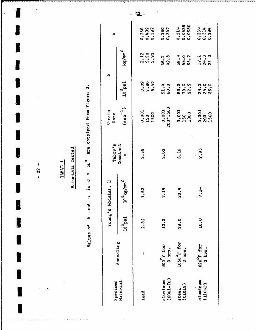
Specimens of four different materials were tested at room temperature
(Table 1). As explained above, the purpose is to find a method which can be
uksd to predict the dynamic yield stress of a material at a given strain and a
given strain-rate from the results of dynamic indentation tests. For coeparison,
stress-strain curvv ves r ,*tained in more conventional simple compression tests
at various constant strain-rates. However, to check the applicability of Tabor's
espiricai foimulae indentation and simple cospression tests were also performed
under static conditions.
(1) Static Indntattion Tests
- 11 -
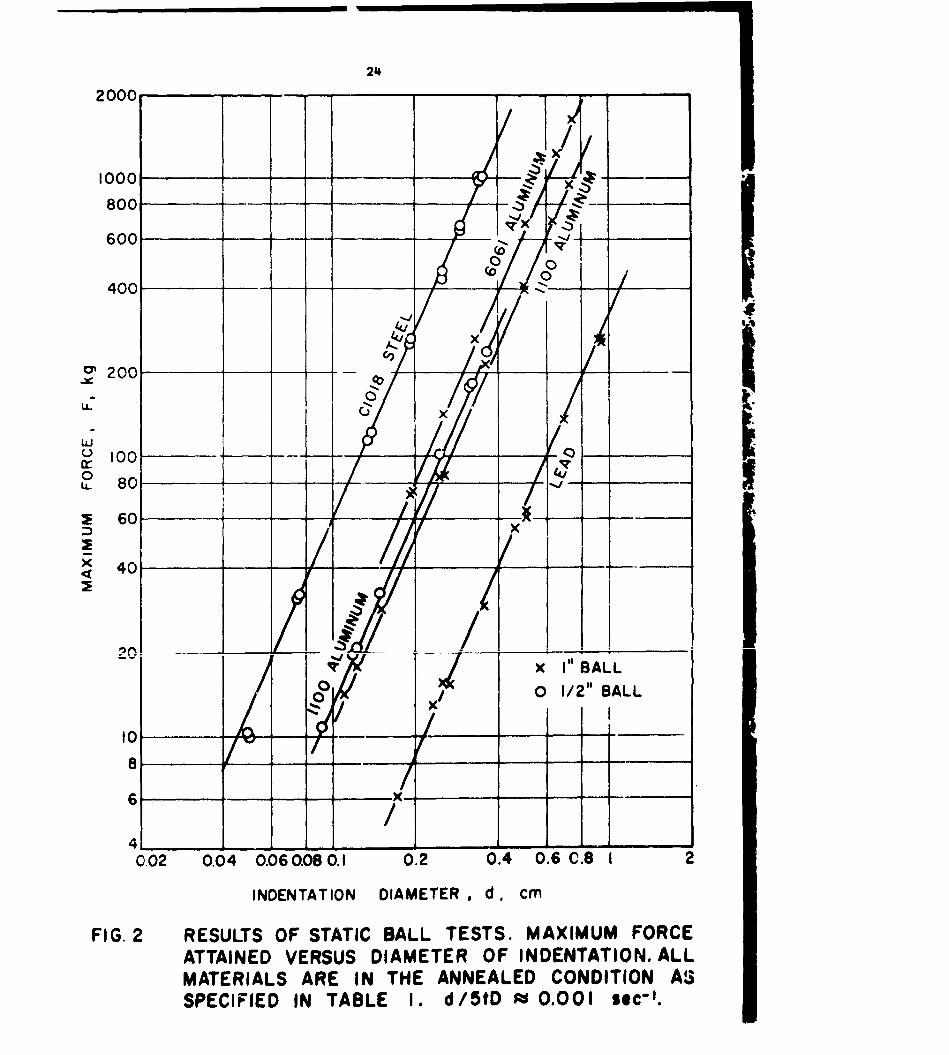
polished surface of a 1 1/2 in. thick specimen. In each test the maximum load,
F , was recorded and the diameter of the permanent indentation, d , was
obtained by averaging four measurements made with a microscope. The pressing
speed was held constant and chosen to keep the quantity d/5tD approximately-i
equal to L.001 rec , where t is the total time of loading measured with4
a stop watch. Results are oresented in Figure 2, and in Appendix C.
(2) Dynamic Indentation Tests
The experimental technique is the same as that described in Reference
[9] to which the reader is referred for details. The specimens were again of
6 in. dia. and 10 in. in length, but only steel balls were used as indenters
In each test, impact velocity , indentation diameter, poefficient of resticution
and time of contact during impact were measured. Results are presented in
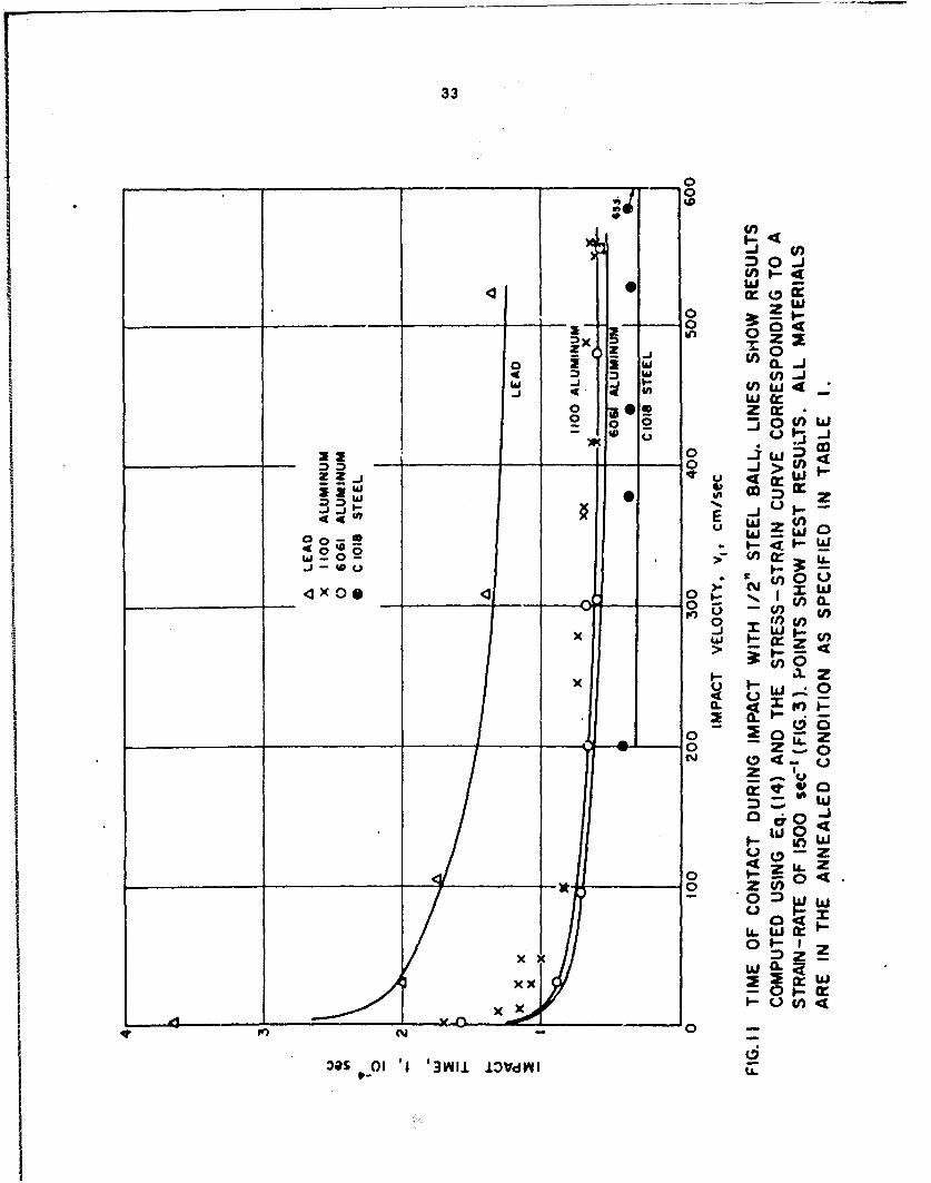
Figures 9 to 12 and in Appendix C.
(3) Static Tests in Simple Compression (Strain Rates z 0.001 sec-1)
Cylindrical specimens 1/4 ik.. long and of 1/4 in. dia. were compressed
between two parallel surfaces of hardened n*t.l 1Ihyfr.tael with a -ranhite oil
mixture. (For lead the specimens had a 3/8 in. dia.) To make sure that the
influence of friction was negligible, a few specimens of greater length were
tested and found to give the same -esults to within the estimated experimental
3ccuracy. In each test the load and deformation were recorded continuously and
the true stress and true strain computed taking the material as incompressible.
Results for the four metals tested are presented as the solid lines in Figure 3.
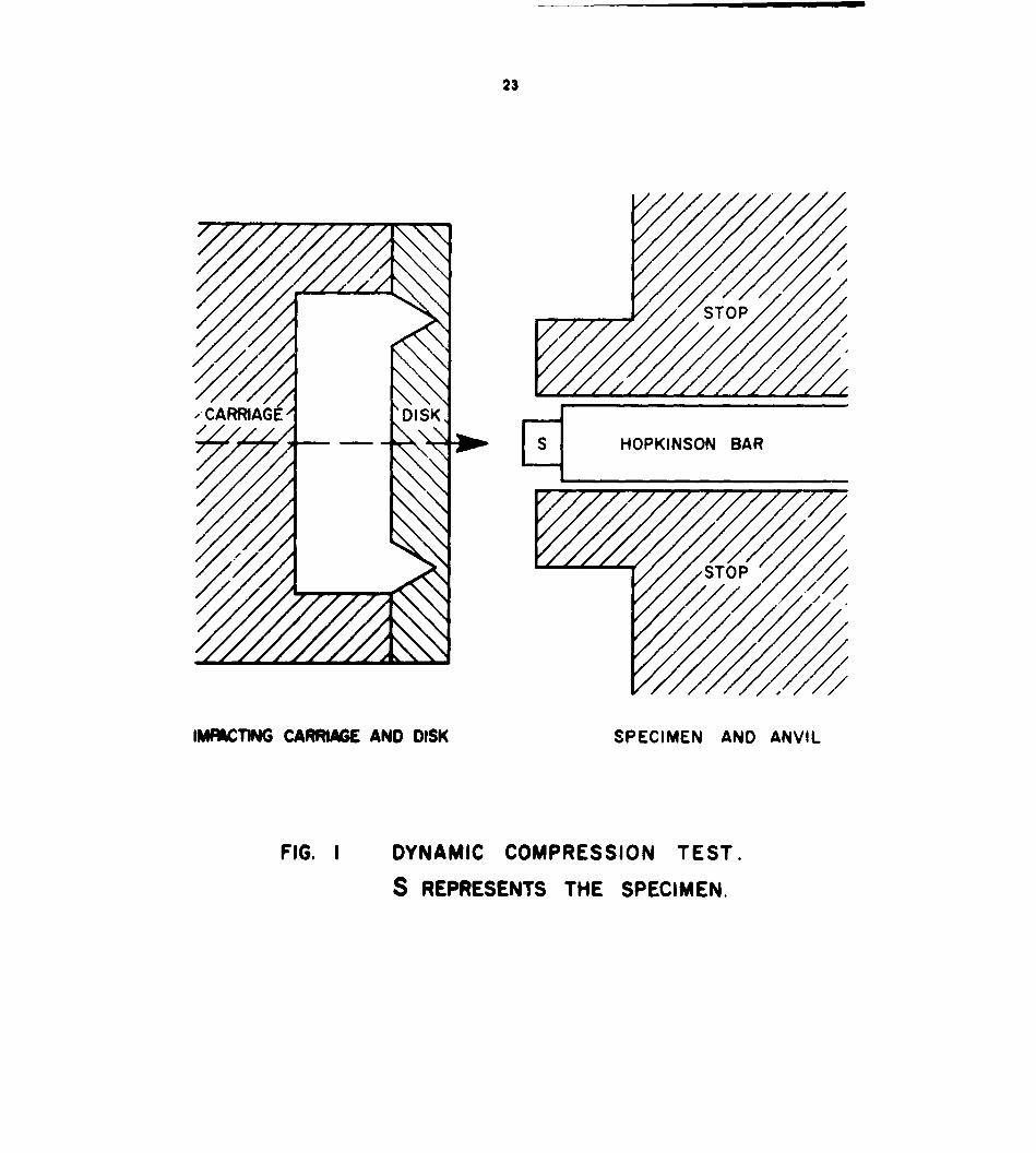
(4) Dynamic Tests in Simple Compres3ion
Circular cylindrical specimens of the same dimensions as those tested
in the static compression tests were compressed against a Hopkinson bar by the
impact of a carriage travelling at velocities between 100 and 1,000 cm/sec.
- 12 -
The method of Karman and Duwez [(14 was adopted to keep the strain-rate as
nearly constant as possible throughout the test. Fo, this purpose the carriage.
was made very heavy (10 lbs) and a disk of brittle material placed in front of
it which fractured shortly after impact and before the velocity of the carriage
changed substantially (Figure 1). Besides holding the strain-rate nearly con-
stant, this technique makes it possible to control fairly closely the total
deformation in the specimen. Each test provided one point on the stress-straii
curve, namely, the maximum strain and the presumed correspondiag stress. The
difference between the final and the initial lengths of the specimen gave the
maximum strain, and the stress was found from the force pulse as measured with
the Hopkinson bir (a slender bar with strain gages which was calibrated under
both static aid dynamic loading conditions). The average strain-rate was
evaluated as the total strain divided by the total time of loading as measured
on the force pulse record.
It is felt that the above set-up provided fairly closely the desired
experimental conditions. A number of tests with specimens of various
dimensions gave substantially the i-snm _eal-!tst, :- thz. tha ;1fluence of wd-@es
within the specimen and of the end conditions probably was not great.
Calculations based on Davies' results (15J indicated that the geometrical
dispersion within the Hopkinson bar should not affect the measurement of stress.
For a further critique of the technique the reader is referred to the work of
Kolsky [16] and of Hunter and Davies[172.
Figure 3 presents the results of this experiment in at true stress-true
strain plot. Dotted lines are drawn through the data points obtained for each
material at each of two averaged strain-rates, namely - 150 and - 1,500 sec 1 .
These results agree with the work by Lindholm 11o], Manjoine [19], and Johnson
ot al. (20]. It can be "sen that for a constant strain the yield stress
- 13 -
increases with strain-rate. This dependence on strain-rate is greater for lead
and steel (approximately 100%) than it is for either of the two aluminum alloys
(approximately 20%).
IV. Analysis of Test Results
(1) The Yield Stress as Found in Simple Compression and in Indentation Tests
(a) Static Yield Stress
The m'.ximum yield pressure in the static indentation lests is found by
dividing the maxim-am force, F, as given in Figure 2, by the area of the perma-
nent indentation, d 2/4 . The stress and Strain are computed using Tabor's
formulae, Equations (1) and (2), and the resilts compared to the static strain-
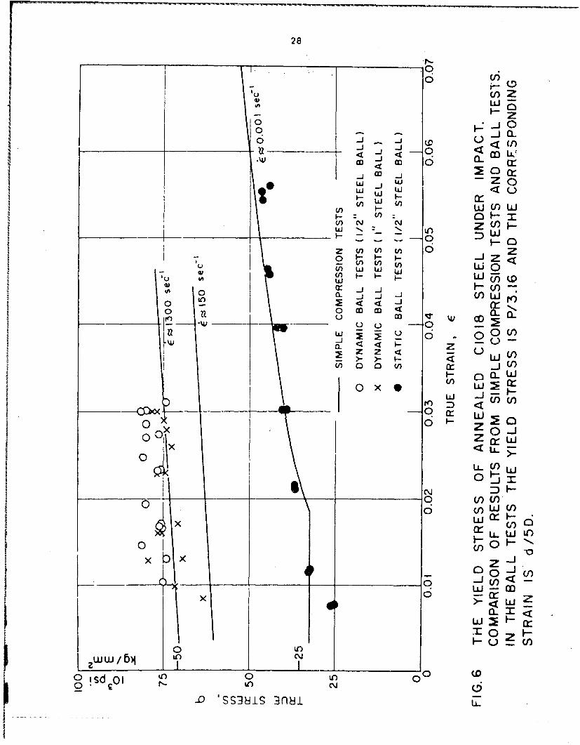
stress curve obtained in simple compression (Figures 4-7). As may be seen from
the figures, the ratio of the yield pressure obtained in indentation tests to
the yield stress found in simple compression remains substantially constant.
However, for three of the materials tested the value of this cinstant c is
nearer 3.0 than it is to Tabor's ?.8, and in the case of lead has a value of
3.59 (Table 1). The reason that lead has a higher value of c is apparently
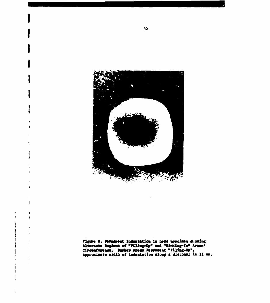
due to a difference in its yield mechanism. Lead showed non-axial symmetric
yielding both in the simple compression and in the indentation tosts. In
simple coq-ression lead yielded along two shear planes oriented at about 450
to the axis of the cylindrical specimen, while the indentation produced by the
bail appeared from above to be a square with rounded comers, (Figure 8). This
appearance is due to an alternate "Piling-up" and "Sinking-in" of the material
as one goes around the circumference of the indentatior. In contrast with the
behavior of lead both aluminum and steel deformed symmetrically. In aluminum
in simple compression the slip lines on the wall of the cylindrical specimen
are parallel to the axis. In steel they are helice., In the indentation

- 14 -
tests with aluminum and steel the indentation appi'ared circular. lowever, the
slip lines for aluminum lie along a radius whereas they are spiral3 For the
steel.
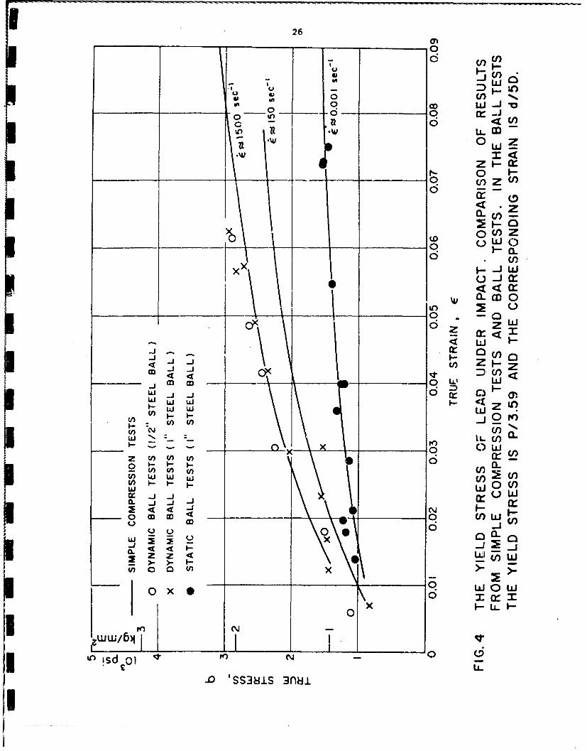
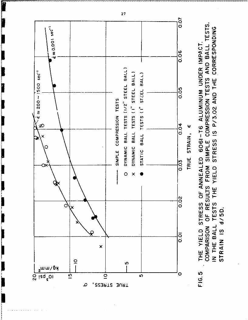
(b) Dynamic Yield Stress
The results of the dynamic indentation tests are interpreted in terms
of a dynamic yield stress and a corresponding strain by using Equation (7) for
the dynamic yield pressure and Tabor's formulae, Equations (1) and (2). Ira
accordance with the analysis given above, the slope of the log vI - log d curv,
provides the necessary value of a in Equation (7), while the value of c in
Tabor's formulae is taken as equal to that found statically (Table 1). The
yield stress thus obtained is compared in Figures 4-7 with the results of the
dynamic compression tests. For all four materials and irrespective of the
indenter the best agreement is found with the stress-strain curve obtained it,
dynamic compression tests performed at a constant strain-rate of approximately-l
1,500 se. The reason for this is not clear. In view of the fairly wide
range of iWpct velocities in the experiments (2 cm/sec to 600 cm/sec) and the
corresponding change in the values of the average strain-rate as measured by
d/5tD (about 20 times), one might believe that the strain-rate would var,
considerably during a given test as well as from test to test. There are,
however, two effects which when combined, might produce the present experimen
tal result. The first is geometric. When a ball is pushed into the plane
surface of a body, the volume of the indentation increases as the square of
the depth of penetration. This means that the more significant part of the
impact, in terms of metal deformed or energy dissipated, wilt come near the
end of the plastic stage. Therefore, the properties of the metal near the end
rather than at the start of impact wi.ll be dominant. In a low velocity impact
the depth of penetration is small and this difference is not important, but in
IN 115.WV-
- 15 -
impact at a high velocity the end of the plastic stage will be dominant and by
then the ball is moving much more slowly and the strain-rate is decreased.
Hence, the total (or average) response of the metal will not be influenced
greatly by the high yield stresses produced by the large strain-rates at the
start of impact. Therefore, the influence of impact velocity on the average
yield stress is small. In addition to the effects of geometry, a second
factor which influences results involves the variation of the yield stress with
strain-rate. In general, the yield stress of metals and alloys does not
change greatly with a change in the magnitude of the strain-rate. If then
the piecise value of the strain-rate is not important, then an average strain-
rate becomes more meaningful and the indentation test provides a good measure
of the dynamic yield stress.
Other investigators have obtained similar results as regards strain-
rate. Goldsmith and Yew [21] measured the impact force as a conical indenter
entered a specimen. They found that to a first approximation the dynamic
force-indentation curves are independent of impact velocities ranging from
1,800 cm/sec to 10,500 cm/sec and that these curves always lie above the
static force-indentation curves. A similar result was obtained by Goldsmith
and Lyman [7] using balls as indenters.
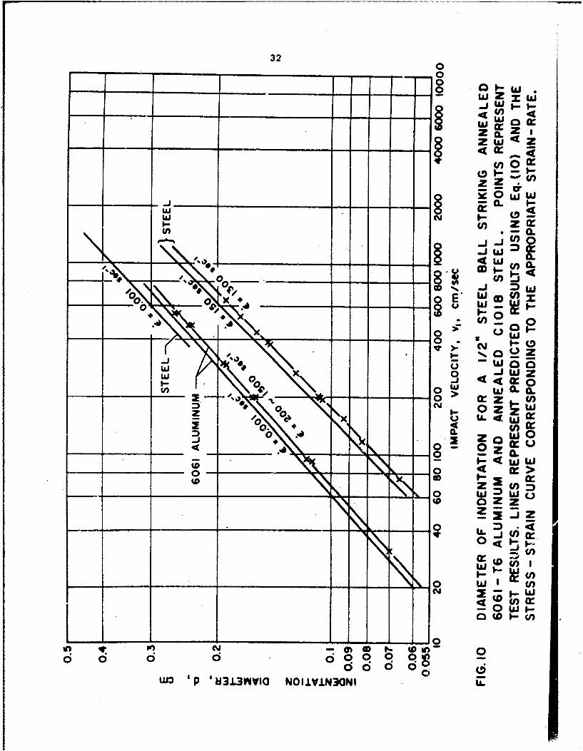
As shown below, the diameter of the indentation is predicted quite
accurately by employing a model consisting of a plastic work-hardening stage
corresponding to a constant strain-rate of 1,500 sec 1 . It is felt that this
agreement provides further evidence tending to confirm the validity of the
present analysis.
(2) Predictions of Indentation Diameter, Contact Time during Impact and
Coefficient of Restitution
(a) Indention Diameter
I -16 -
3 The diameter of the indentation remaining in the specimen after imp
at a given velocity is predicted above by Equation (10). The parameters b
U and n, which define the stress-strain relation of the material, are eval.-
uated from the results of tests at constant strain-rates (Table 1). Predic
values of the indentation diameter are plotted in Figures 9 and 10 for a ra
5 of strain-rates and compared to experimental values. *The best agreement fc
all metals is found if one chooses a strain-rate of 1,500 sec. .
3In addition to predicting correctly the size of the indentation, h.
analysis predicts quite accurately the dependence of the indentation diamet
on the impact velocity. It will be recalled thit according to experimencA.'
results, d is proportional to va where a i3 a constant independen, oi
size of the ball [9]. If one uses for each metal the stress-strain curve
corresponding to a strain-rate of 1,500 sec"I, then Equation (10) predict.
that a will have a value of 0.455, 0.460, 0.466, and 0.'93, respectively,
the lead, 6061 aluminum, 1100 aluminum and C1018 steel. Experimental r,,sult
3 give for the same quantities values of 0.441, 0.456, 0.466, and 0.491,
respectively, for the same metals. A perfectly plastic theory of impact pr
3 dicts that a will equal 0.50 r9l.
3 (b) Impact Time
The total time of contact during impact is predicted using Equatio.
3The parameters in this equation which depend on the properties of the specir
i.e. b and n , wee evaluaed from the results of the simple compression
3 tests run at a strain-rite of 1,500 sec". A comparison with experimental
3results is presents I Figure 11 for the fouL materials tested. Agreement
good except in the 1 ir velocity range. This discrepancy may be due to the
I fact that the initial elastic stage ij neglected in deriving Equation (14) an
that this stags becoms more Important at lower velocities.I
- 17 -
For eacn material the numerical value of the function G in
Bruation (14) var.ies no more than 10% for the range of velocities fvom 2 to
600 cm/sec. As a result, for any of these materials t is approximately
proportional to (mID)I/2 (mv 1 /D3)8/2 where 0 = -(I ÷ n)/2(4 + n). From the
results of simple compression tests, Table 1, the numerical value of b was
found to lie between -0.13 and -0.16. Dimensional analysis [9) also indicates
that t is proportional to the above factor and according to the results of
the indentation tests 8 lies between -0.13 and -0.19 (including tests at
elevated temperatures).
(c' Coefficient of Restitution
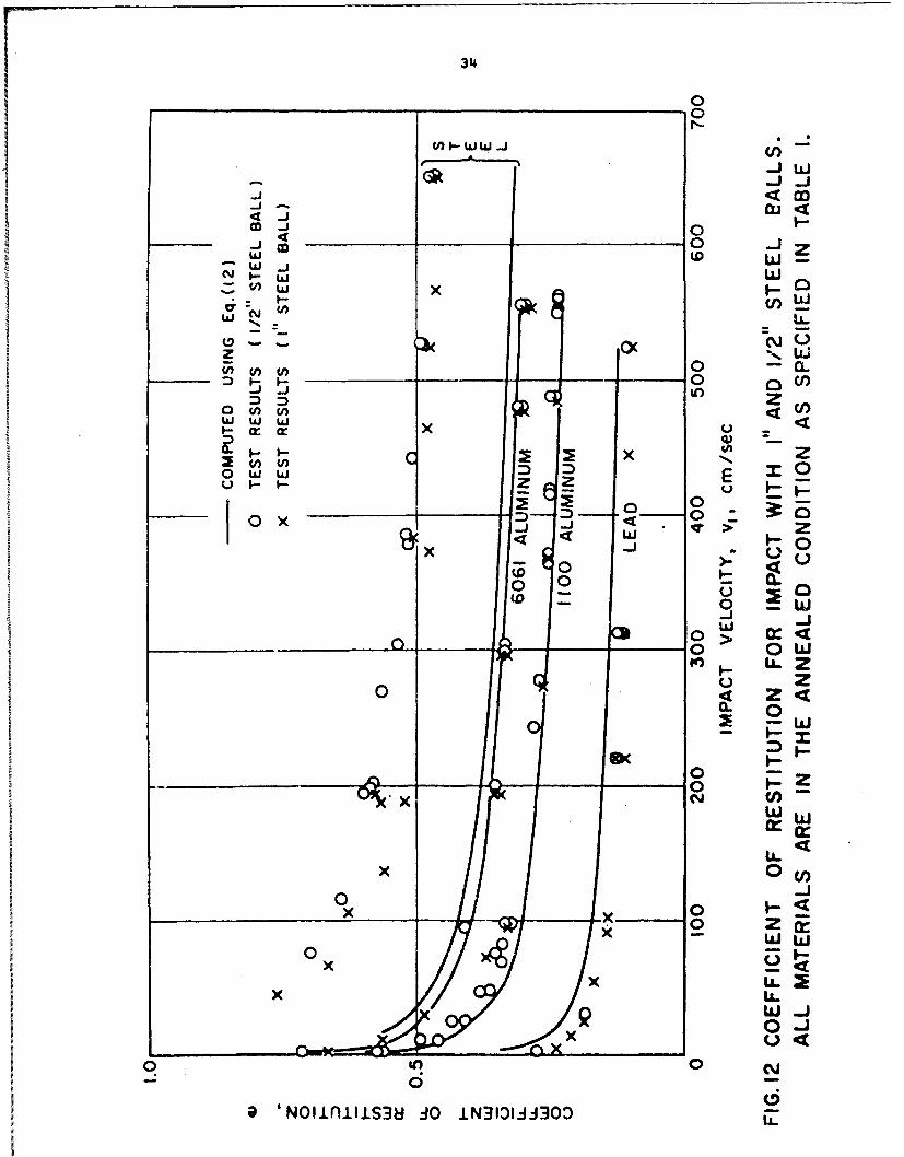
The coefficient of restitution as predicted using Equation (12) is
compared to measured values in Figure 12. In the calculation of the coefficient
of restitution values of b and n were obtained from the stress-strain
curve corresponding to a strain-rate of 1,500 sec" , and those of B and N
from the static curve (corresponding to a strain rate of 0.001 sec 1). In
addition, the values of E for the specimen and ball were taken from Table 1,
whereas v is always equal to 0.3. It is shown that over the range of
velocities Equation (12) gives a good prediction of * for all materials
tested except steel, In the case of steel, the error in the prediction is
approximately 50%.
a|
1 -18-
I CONCWSIONS
I It is shown that the dynamic yield stress of a metal can be predicted
over a range of strains through a proper interpretation of the results of
I indentation tests. Experiments performed on four metals give values of the
yield stress which agree closely with the results of impact tests in simple
compression. Thu- in spite of the complexities of the indentation problem,
can give an accurate measure of the yield stress. This conclusion is import-
because the indentation test is easily performed even at elevated temperati.
At first sight, it is surprising that this degree of success is achieved in a
test in which the results are sensitive only to averaged or integrated va±•c.
I of stress and of strain. The reason probably lies in the geometry of the
colliding bodies combined with the fact that yield stress is not very sensit"
to changes in strain-rate within the limits of the present experiment. Thi-
f question is discussed further in the text. As far as actual values are con-
cerned, it was found that the yield stress for lead and aluminum is approxi-
I mately twice as great dynamically as statically over the range of strains; fo.
aluminum the difference is only about 20%.
One can predict also the magnitude of the diameter of indentatior. th.
total tine of contact, and the coefficient of restitution using a simple mode.
in which the specimen exhibits plastic work-hardening during loading and au
I elastic recovery. If the strein-rate during plastic work-hardening is taken
at a constant 1,500 sec1 , a very accurate prediction of the diameter G.f the
indentation is obtained over tha range of impact velocities. This is true of
the four metals tested. As explained above, this agreement is probably due tc
geometry effects and to the mamner in which yield stress depends on strain-rat
1 Instead of the model used in the present investigation, the yield stress could
I
- 19 -
be made to depend on the strain-rate and not on the strain. However, one can
show that in predicting results such a model is f& inferior to the strain-
hardening •ne.
An earlier set of experiments indicated that for each metal a power
relation exits between the diameter of indentation and the velocity of the
ball at impact [9]. It is evident that this velocity-indentation relation
must depend on the dynamic stress-strain relation of the metal. The present
investigation shows that a work-hardening model and a stress-strain relation
of the form a = bcn can be used to predict accurately the velocity-indenta-
tion relation, and furthermort that the material constants b and n deter-
mine the magnitudes of the parameters in this velocity-indentation relation.

- 20 -
BIBLIOGRAPHY
1. Tabor, D., The Hardness of Metals, Oxford University Press, 1951.
2. Goldsmith, W., Impact, Edward Arnold Ltd., London, 1960.
3. O'Neill, H., The Hardness of Metals and its Measurement, Chapman and Hall,London, 1934.
4. Davies, R. M., "The Determination of Static and Dynamic Yield StressesUsing a Steel Ball," Proc. Royal Soc. of London, Series A, Vol. 197,1949, p. 416.
5. Martel, R., "Sur la Mesure de la Durete des Metaux," Comnission desMethodes d'Essai des Materiaux de Construction, Paris, vol. iii,Section A (Metaux), 1895, p. 261.
6. Crook, A. W., "A Study of Some Impacts between Metal Bodies by a Piezo-Electric Method," Pzoc. Royal Soc. of London, Series A, Vol. 212, 1952,p. 377.
7. Goldsmith, W. and Lyman, P. T., "The Penetration of Hard-Steel Spheresinto Plane Metal Surfaces," J. Appl, Hech., Vol. 27, 1960, p. 717.
8. Yew, C. H. and Goldsmith. W.. "Stroan 1Dintr4hi,,t1ione in Soft NWI.:-L dau- tStatic and Dynamic Loading by a Stwl Sphere," Report of Institute ofEngineering Research, Unives Ity of California, Berkeley, California,U, S. A., Serie No. 193, Issue No. 1, August, 1962.
9. Hok, C. H. and Duffy, J., "The Behavior of Metals at Elevated Temperaturesunder Impact with a Bouncing Ball," Nonr Report 562(20)/33, April, 1963,Division of Engineering, Brown University, Providence, Rhode Island, U.S.A.,(to be published in the International Journal of Mechanical Sciences).
10. Schneider, J. J., "Die Kugelfallprobe," Zeit. des Vereines deutecherIngenieure, Vol. 54, 1910, p. 1631.
11. Hunter, S. C., "Energy Absorbed by Elastic Waves during Impact.," J. Mech.Phys. Solids, Vol. 5, 1957, p. 162,
12. Johnson, K. L., "Reversed Plastic Flow during the Unloading of a Spherical
Indenter," Nature, Vol. 199, 1963, Ro. 49009 p. 1282.
13. Hertz, H., Miscellaneous Papers, M1acmillan, London, 1896, p. 161.
14. Karman, Th. and Duvez, P., "The Propagation of Plastic Deformation in
- 21 -
15. Davies, R. M., "A Critical Study of the Hopkinson Pressure Bar," Royal Soc.of London, Phil. Trans., Section A, Vol. 240, 1948, p. 375.
16. Kolsky, H., "An Investigation of the Mechanical Properties of Materials atVery High Rates of Loading," Proc. Phys. Soc. of London, Series B, Vol. 62,1949, p. 676.
17. Hunter, S. C. and Davies, E. D. H., "The Dynamic Compression Testing ofSolids by the Methods of the Split Hopkinson Pressure Bar," Part I.The Theoretical Mechanics of the Experiment, Report (MX) 7/60, BritishArmament Research and Development Establishment, Fort Halstead, Kent,England, 1960.
18. Lindholm, U. S., "An Experimental Determination of the Stress-Strain RateRelations of Several Metals," Ph.D. dissertation, Michigan State University,East Lansing, Michigan, U.S.A., 1960.
19. Manjoine, N., "Influence of Rate of Strain and Temperature on Yield Stressesof Mild Steel, " J. Appl. Mech., Vol. 11, No. 4, 1944, p. A211.
20. Johnson, J. E., Wood, D. S. and Clark, D. S.,"Dynamic Stress-StrainRelations for Annealed 2S Aluminum under Compression Impact," J. Appl.Mech., Vol. 20, 1953, p. 523.
21. Goldsmith, W., and Yew, C. H., "Penetration of Conical Indenters Indentersinto Plane Metal Surfaces," Proc. 4th U.S. National Congress of AppliedMechanics 1962, p. 177.
3 nC'O M M 0*z HLM tn to -- c~CA( (v~i miO N C A
c* .l . . & .4 0000~ 00 000 000
N04~
m~O NC' iOn W)t -40C4 C
.,1* 04n4 -NN
to4 000 *0H 000~ 0 a00
V4r~ 14O N ~ 0 to LA
[-4 0
41 N~4 I) ~ . I() * u
U~b (D 4 Cv
N N
1,0
00 .4 *4
bo
N-0 0 0
c 0 4. WV0. 40* 0
Cto
4(,
0) 41 0 4)040 * 4.4 Q *
(n fnCo C
23
S HOPKINSON BAR
00/ E
STO
-IM G CARRIME AND DISK SPECIMEN AND ANVIL
FIG. I DYNAMIC COMPRESSION TEST.
S REPRESENTS THE SPECIMEN.
214
2000__ _
1000
800 IOOOX----
600 d ...
(0 o400 7 -
"I X
~200 £9)
uJcL
o 60_ _" _ / _ _
-- I' SALL
0 0 1/2" BALL,o -, /-_ _'
8 /_ , .... .
4002 0.04 0.060.08 0.1 0.2 0.4 0.6 C.8 I 2
INDENTATION DIAMETER, d, cm
FIG. 2 RESULTS OF STATIC BALL TESTS. MAXIMUM FORCEATTAINED VERSUS DIAMETER OF INDENTATION. ALLMATERIALS ARE IN THE ANNEALED CONDITION AS5SPECIFIED IN TABLE I. d/5tD P 0.001 sec-'.

25
j0 L
__ - oz
_ _0 Z
00
0 n 0
*q cr u,0
4>0T 0 0 M
0 0 __j Df~
I N-
00 zW011-x
0 2 0
4UJ
\Iw o 0Z
0~~ ~ 00 0
.0 0 S~L (n0IW
L a
_ _ _ ~~26 _ _
0
0 F-ON
.7 cj, %%
R U- CO0 0
.. 4
oz.4,/
2
-_ _ _~ -- /_ 0 IU oC
6C
0
00
cyx 0 z Z-r < X 1
U))
Lt o 0 Lo
W W W
U'Cl j)'
W .,: t L (f) a
cn U) 0l w'
0 cn cn(n
a, W 0U)
ox wow
w 2CLI
ww/6M-O s~
. SS38iS 3fl~i.
_ _ _ _ _ _ _ _ 27 _ _ _
00
cz~0 z1
-0_ _ 0- ino0 6t
wL 0
II- _ _ -
0I 0
N W =4 -- 0-
z z D) Vj)0).W Z wI0
(n (1)
M _-
I 6 DI 0nI I 0
~'sdoi U
0 'Sx1~ 0Jl. < 0
I r
28
~0 (n)
Hz
0 0 0
LiiL
a-Z ) U) oU 0 W
V)() W 1 r
V) N) N U
ZZ 4 -- V
0 zoz
W L~
W ~ w LLJ in w
z-J
L) c o
I~~ zwlz L. 0 (
Oisdo Wn U)N-D~~: <S~dS f~

29
cfJ)
V)
0 0 -1 a
0 < U0
-J w Wz4 Z
_ _ _ _ _ 0
a) z <
U) D 0) w
~ ~ w
~4 z :D 0 - 0010 z
44- 2- - 0 WZ Z 4(f
U) 00 'Ji LU
w ~ a-- CL~
2 (/w)U)
w - H
01>V
0 x 0.w1a
LI/~~ .0 _S38S3f
30
It ~uinI Tsd"b hw"AIetf PXO fOLa4"m *bIgI"Ae-
Ilefixe *D4MA WIpem Pln-pAprxmt it fidnaio ln ignli 1M
31
4- W
ZWZ
00z
~Ja
wJ 5
zow
COO.
0 ClU
~W IiJ
# A i 0 . 0 1--
W z
> 0 _0 '16 0iw~~~~ 'p W 0:3lI OIV.3N
320
-0
_ _ _ _ _ _ 4
Z0~
Z ZZ~
w w--ow I-
02 0- O W 0 t3 4
w U
N 0 JW
I. < 0:-00 > U rZ U
z 0. * LL4 cr0 .4 0.
8- -g C
o ) m
z-0-
W ~~~ ~ ~ ~ : 'p Z~iVVO NOI±3N
33
U)
00-w
z o
w 4 w Cl4
2 0 -1o
I o w CI
- w
_ _ _ _ _ _E - _ _ _
400
_ _ _ _ 0k. 2% cn-C U,
w Y
0~ 01 U)
x W I.- WW
xr 'Dd; -4o
____ ____ ____ ___ ____ ____ ___34
_ _ _ _ _ _ _0
0
I,.
4ww -J0w
oo
z x g.0
0 CCI
U)) z
~I ~J0 CL
~ 0 -
__ M_ 0>00 O
0w -w
0_ _0_ 0
0
0 IL
oL 00w
~ 'NI~fhtiS8 :O LNI3II3x

- 39 -
APPENDIX A
Review of Previous Work
In one of the early iml.-.L hardness experiment., Martel El] showed "
over a wide range of experimental conditions the volume of the indentation
formed by the indenter striking the specimen surface was directly proporti-
to its kinetic energy. On the basis of this observation he suggested that
throughout the impact process the indenter was resisted by the specimen i
I constant yield pressure which may be calculated from the total impact energ
the indenter and the volume of indentation. For a ball of diameter D, mas.
m , striking with a velocity v1 to form an indentation of diameter d ai.
specimen surface, the constant yield pressure is given as
(p) .1 mv 2 Ad4/32D) (Al)
according to Martel. In the investigation of plastic impact problems, later
Sworkers (e.g. Andrew C2 to 4] and Tabor (5]) tried to perfect Martel's mcdu
including tht elastic properties of the material and found some agreement be
the experimntal values of the coefficient of restitution, diameter of inden
i tion, impact time and their theoretical predictions. Tabor also suggested
in the zzlculation of a mean yield pressure, the rebound energy should be su
I tracted from the total impact energy and that the elastic recovery within th
I indentation should be taken into account. H.d obtained
( (1 - e 2)( I mv2)/(id /32D) (A2)
whrre e is the coefficient of restitution defined as the ratio of rebound
I velocity to impact "elocity. Firthermcre, looking at only the rebound proc.
!
- 36 -
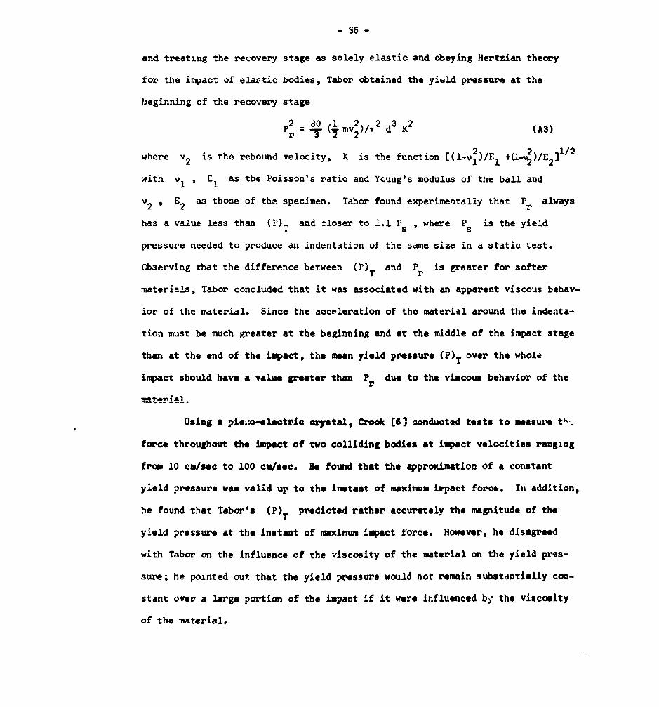
and treating the recovery stage as solely elastic and obeying Hertzian theory
for the impact of elaotic bodies, Tabor obtained the yield pressure at the
beginning of the recovery stage
p2 =8(.mv)/w80 1 2 d23 2 (A3)r 3 22
where v2 is the rebound velocity, K is the function [(l-v2)/E1 +(l-v2 )/E 2 /
with v, , E, as the Poisson's ratio and Young's modulus of the ball and
u2 , E2 as those of the specimen. Tabor found experimentally that Pr always
has a value less than (P)T and closer to 1.1 Ps , where Ps is the yield
pressure needed to produce an indentation of the same size in a static test.
Cbserving that the difference between (P)T and Pr is greater for softer
materials, Tabor concluded that it was associated with an apparent viscous behav-
ior of the material. Since the acceleration of the material around the indenta-
tion must be much greater at the beginning and at the middle of the impact stage
than at the end of the impact, the mean yield pressure (P)T over the whole
impact should have a value greater than Pr due to the viscous behavior of the
Using a pie-'o-electric crystal, Crook [6] conducted tests to measure t-_
force throughout the impact of two colliding bodies at impact velocities ranging
fros• 10 cm/sec to 100 cm/sec. He found that the approximation of a constant
yield pressure was valid up to the instant of maximum impact force. In addition,
he found that Tabor's (P)T predicted rather accurately the magnitude of the
yield pressure at the instant of maximum impact force. However, he disagreed
with Tabor on the influence of the viscosity of the material on the yield pres-
sure; he pointed out that the yield pressure would not remain substmntiatuy con-
stant over a large portion of the impact if it were influenced by the viscosity
of the material.

-37-
I The concept of a constant yield pressure, however, seem to be in(
3sistent with the fact that for most materials the yield stress has been fc
depend on strain and strain-rate. Recently, Goldsmith and Lyman [7] meast
the force of impact at velocities ranging from 750 cm/sec to 4,500 cm/sec
found that yield pressure did not remain constant throughout the impact.
also found that for some materials a higher yield pressure was obtained .r
3 dynamic than under static conditions. In another paper with Yew [8), Gol
again indicated the dependence of yield pressure on strain and strain-it,
3 measuring the internal strain distribution pr'oduced in a lead specimen by
impact of a ball.
In a previous paper [9), the authors pointed out that the yield .
calculated with Tabor's formula, Equation (A2), was dependent on the impa
velocity and presumably the resulting strain and strain-rate. In additin,
3 of impact velocity against indentation diameter on a log-log coordinate
showed slopes different from the 0.5 value based on constant yield pressui
concept.
ci Experiments with conical indenters (10] also indicated that the yi
pressure was straLn-rate dependent. Using the results of dyfiamic and stit
I g indentation tests with a quasL-static method of analysis and the cor ;tant
piessure assumption, Davis and Hunter (11 and 12] obtained a ratio of dyna
static yield pressures. This ratio was found to agree approximately wit
3 ratio of dynamic and static yield stresses obtained by other investigators
the same materials in simple -ompression tests.
3At the present time# no rigorous theoretical solution exists for t
indentation problem, even for the idealized rigid-perfectly plastic materl
U Ishlinsky, however, was able to obtain a theoretical solution using the Hs
1 •Karman yield condition aid the slip line method [13]. He found that the a
• I
- 38 -
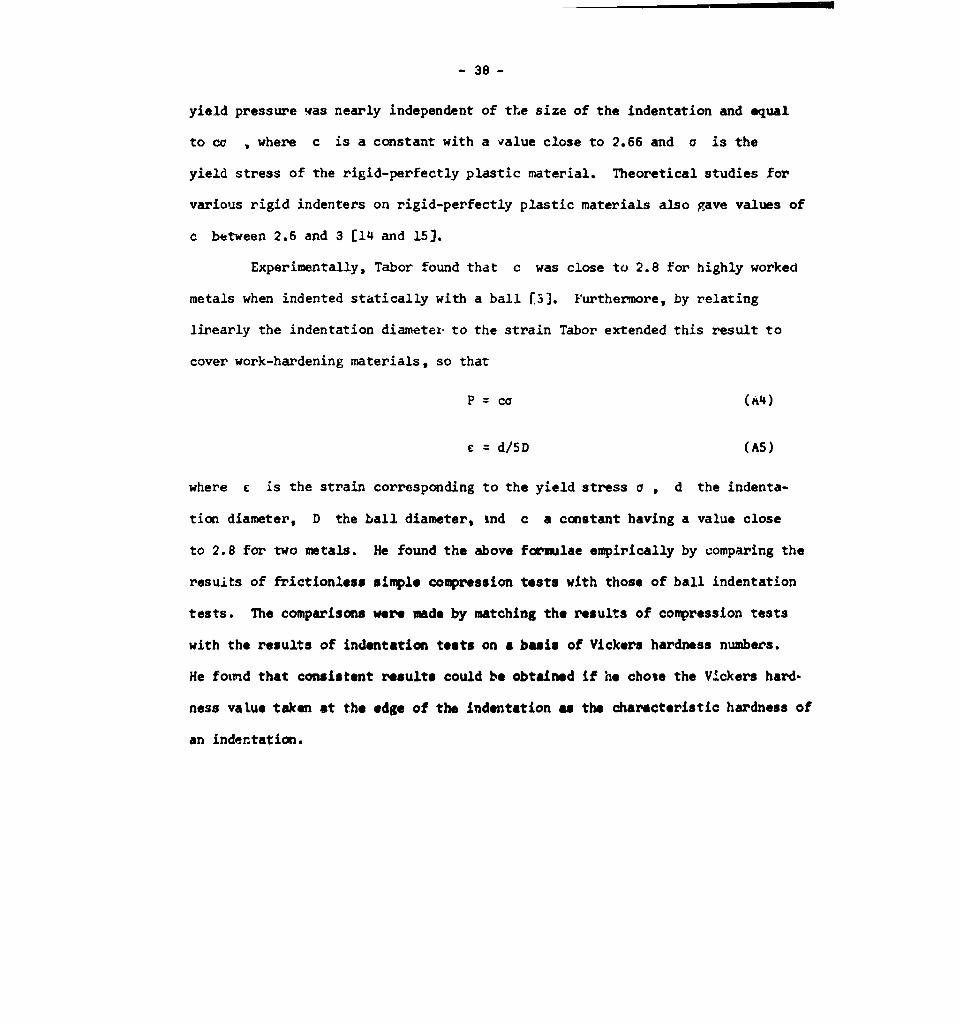
yield pressure vas nearly independent of the size of the indentation and equal
to cc , where c is a constant with a value close to 2.66 and c is the
yield stress of the rigid-perfectly plastic material. Theoretical studies for
various rigid indenters on rigid-perfectly plastic materials also gave values of
c between 2.6 and 3 [14 and 15].
Experimentally, Tabor found that c was close to 2.8 for highly worked
metals when indented statically with a ball F5]. Furthermore, by relating
lirearly the indentation diametex to the strain Tabor extended this result to
cover work-hardening materials, so that
P = cc (A4)
c = d/5D (A5)
where E is the strain corresponding to the yield stress a , d the indenta-
tion diameter, D the ball diameter, ind c a constant having a value close
to 2.8 for two metals. He found the above formulae empirically by comparing the
resuits of frictionless simple compression tests with those of ball indentation
tests. The comparisons were made by matching the results of compression tests
with the results of indentation tests on a basis of Vickers hardness numbers.
He fotud that consistent results could be obtained if he chose the VIckers hard-
ness value taken at the edge of the indentation as the characteristic hardness of
an indentation.
* -39 -
BIBLIOGRAPHY FOR APPENDIX A
1. Martel, R.s "Sur la Mesure de la Durete des Metaux," Commission desMethodes d'Essai des Materiaux de Construction, Paris, Vol. iii, Sectio5 (Metaux), 1895, p. 261.
2. Andrews, J. P., "Theory of Collision of Spheres of Soft Metals," Phil. I
Vol. 9, 7th Series, 1930, p. 593.
3. Andrews, J. P., "On the Impact of Spheres of Soft Metals," Phil. Nag.,Vol. 8, 7th Series, 1929, p. 781.
I 4. Andrews, J. P., "Experiments on Impact," Proc. Phys. Soc. of Londou,Vol. 43, 1931, p. 8.
3 5. Tabor, D., The Hardness of Metals, Oxford University Press, 1951.
6, Crook, A. 11., "A Study of Some Impacts between Metal Bodies by a Piez -
Electric Method," Proc. Royal Soc. of London, Series A, Vol. 212, l9b.'-p. 377.
7. Goldsmith, W. and Lyman, P. T., "The Penetration of Hard-Steel Spheresinto Plane Metal Surfaces," J. Appl. Mech., Vol. 27, 1960, p. '17.
8. Yew, C. H. and Goldsmith, W., "Stress Distributions in Soft MetaL'q dueStatic and Dynamic Loadirg by a Steel Sphere," Report of Institute ofEngineering Research, University of California, Berkeley, California,
U.S.A., Series No. 193, Issue No. 1, August, 12962.
9. Mok, C. H. and Duffy, J., "The Behavior of Metals at Elevated Temperat a,Under Impact with a Bouncing Ball," Nonr Report 562(20)/33, April, 196KDivision of Engineering, Brown University, Providence, Rhode Island U.S.(to be published in the International Journal of Mechanical Scienres).
10. Goldsmith, W. and Yew, C. H., "Penetration of Conical Indenters into PleMetal Surfaces," Proceedings of the 4th U.S. National Congress of ApplieMechanics, 1962, p. 177.
11. Davis, C. D. and Hunterg S. C., "Assessaent of the Strain-Rate Sernsi+.vJof Metals by Indentation with Conical Indenters.," J. Mech. and Payi. SolVol. 8, 1960, p. 235.
1 12. Davis, C. D. and Hunter, S. C., "The Assessment of Strain-Rate Sensitiviby Dynamic Hardness Measurements," Sheet Metal Inductries, Vol. J9, No.1 1962, p. 201.
13. Wilinsky, A. 1u.; "The Problem of Plasticity with Axial Symetry andBrinell's Test," PrLkladnalia Matematika i Mekhanika, Vol. 8, 1944, p. 20
!II
- 40 -
14. Hencky, H., 'EJber einige statisch bestimmte F11. des Gleichgewichts inplastischen Kdrpern," Zeit. ang. Math. Mech., Vol. 3, 1923, p. 241.
15. Shield, R. T. and Drucker, D. C., "The Application of Limit Analysis toPunch-Indentation Problems," J. Appl. Mech., Vol. 20, 1953, p. 453.

I -41l-I
APPENDIX BIm Analysis of the Plastic Work-Hardening Stage
As pointed out in the text, a two-stage moeel of the dynamic indentai
test is employed to predict the indentation diameter, the total time of conti
3 and the coefficient of restitution. This model consists of a plastic work-
hardening stage followed by an elastic recovery stage. The ball strikes the
3 specimen at the start of the plastic stage with an initial velocity v, .
Its subsequent motion during penetration is resisted by a yield pressure, I
I ~dependent Oil the strain (i.e. dependent on the diameter of the contact areai,
Using Tabor's empirical formulae, Equations (1) and (2) and a stress-strair.
tion of the form a = ben , it can be shown that
I P . .cb (a/D)n (B.
3 where D is the diameter of the ball and c is Tabor's constant. For the
motion of the ball, Nrnon's law gives
2v- P x (B2'
3 where m is the mass of the ball and "x the second time derivative of thr
relative approach of the mass centers of the two impinging bodies. II ther,
m not much "piling up" or "sinking in" near the contact area and the ball is
3 then the equation
ah apx tDlx (B3m holds approximately.
ImI

- 42 -
Using Equations (BI), (B2) and (B3), it can be shown that at the moment
of maximum relative approach (or of zero velocity of approach) the diameter of
the area of contact is
l /(4+n¶)
d- f (c,nb) D (mvl/D ) (B4)
where
n 1/(4+n)f 1 (c,n,b) =5 . 4 . (4 + n)/wcb]
when the plastic deformation is pronounced and the elastic recovery is relative-
ly small, this diameter can be considered to be approximately equal to that of
the permanent indentation.
Replacing a with d and using Equation (BO) to find the product cb,
Equation (Bl) gives the yield pressure at the maximum approach, P , as
p 4 (12 1p= _._nvI)/(,rd /,21. .(B5)
As pointed out in the text (Section II), this expre ;ion for the yield pressure
is the same as that derived from the impact test re..;zts.
Equations (BI), (B2) and (B3) can be used tr obtain also the duration of
the plastic strain-hardening stage (the time lapse between the instant when the
impact starts and the instant when the maximum relative approach is attained),
tp , so that
p o a I (f (cn~b)]2 (D/v )(mv 2/D 3:. ) 2 2 2/(4+n) 06)v1
where x° is the maximum relative approach between the two bodies and I is
the convergent series
1 13+ 133.56 + n +2*.(5 + n) + 2 -46.(7 + 3n/2) . .
- 43 -
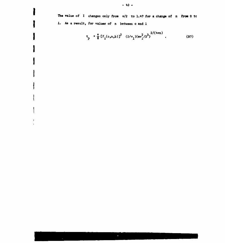
I The value of I changes only from w/2 to 1.47 for a change of n from 0 tc
1. As a result, for values of n between o and 1
1 2 2 3 2/(4+n)
I:=: Efl(cnb)]2 (D/vl)(mv 12/D) " (B7)
I
III

I-4-I
APPENDIX CIResults of Static and PDnamic Indentation Tests
TABLE Cl
Results of Static Ball Tests on Lead using a 1" Steel Ball
d 0.001 sec 1
Maximum Force, F Indentation Diameter, d
(kg) (cm)
6.12 0.17212.9 0,23315.6 0.25315.4 0.26829.2 0.3605600 0,46363.5 0.50561.9 0.507
136 0.697265 0.921266 0.929260 0.948
I
- 45 -
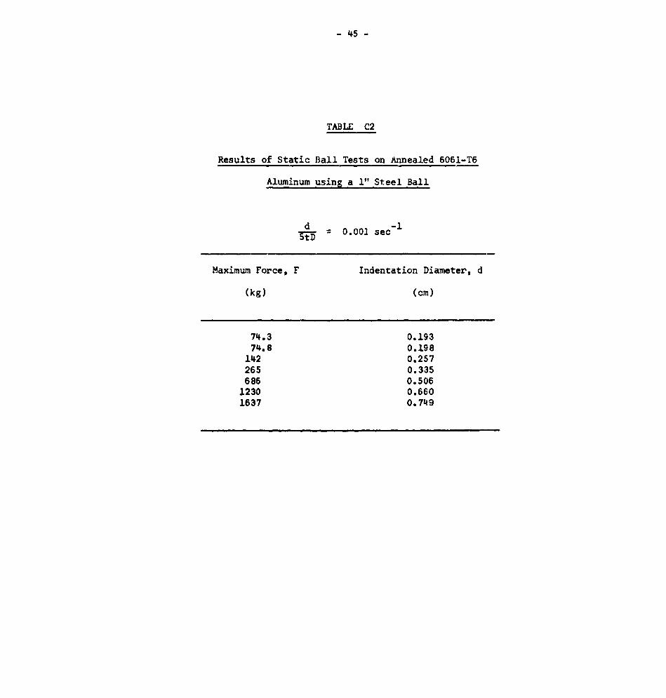
TABLE C2
Results of Static Ball Tests on Annealed 6061-T6
Aluminum using a 1" Steel Ball
d 0.001 see 1
Maximum Force, F Indentation Diameter, d
(kg) (cm)
74.3 0.19374.8 0 .198
142 0.257265 0.335686 0.506
1230 0.6601637 0. 749
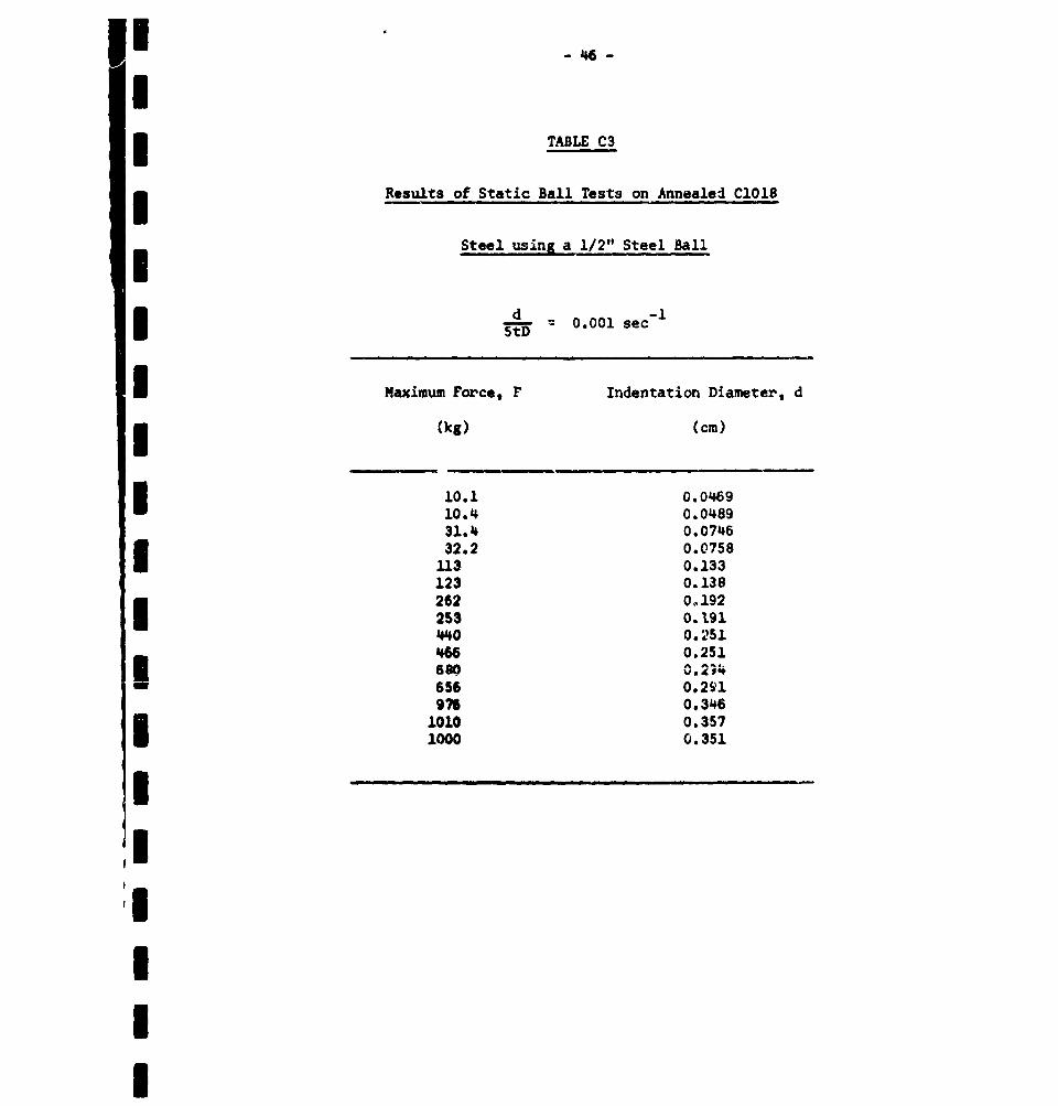
I - 46 --
ITABLE C3
Results of Static Ball Tests on Annealed C1018
Steel using a 1/2" Steel Ball
d 0.001 sec- 1
5tD
I Maximum Force. F Indentation Diameter, d
* (kg) (cm)
10.1 0.046910.4 0.048931.4 0.074632.2 0.0758
113 0.133123 0.138262 0.192253 0.191I40 0.2514"6 0.251ago_ 0.234
I 656 0.291976 0.346
1010 0.3571000 0.351
I,I
II
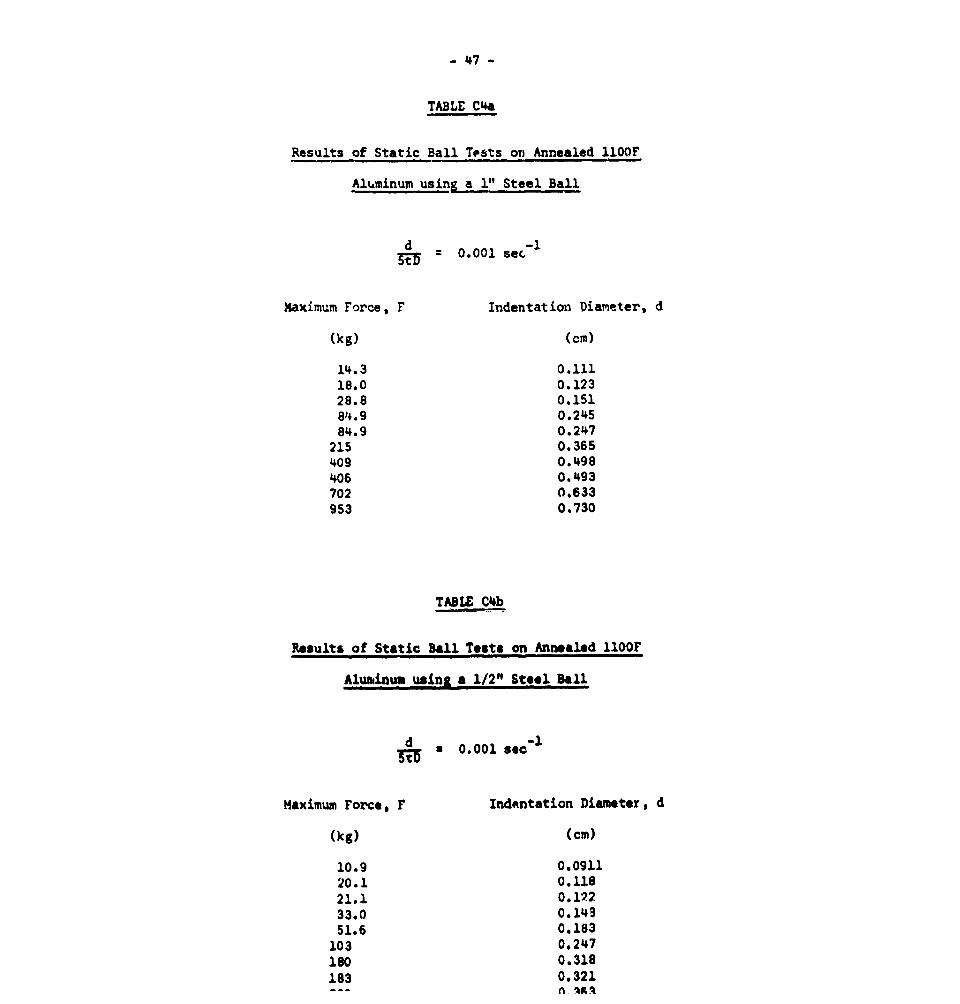
- 47 -
TABLE C4a
Results of Static Ball Tfsts on Annealed 110OF
Aluminum using a 1" Steel Ball
d 0.001 sec.
Maximum Force, F Indentation Diameter, d
(kg) (cm)
14.3 0.11118.0 0.12328.8 0.15184.9 0.24584.9 0.247
215 0.365409 0. *498
406 0.493702 0.633953 0.730
TABLE C'b
Results of Static Ball Test. on Annealed 1OOF
Aluminum using a 1/2" Steel Ball
d * 0.001 sec"1
Maximum Force, F Indentation Diameter, d
(kg) (cm)
10.9 0.091120.1 0.11821.1 0.12233.0 0.14951.6 0.183
103 0,247180 0.318183 0.321
n -%r ,
1 -48 -
I
TABIX CS
K Results obtained with a I" Steel Ball striking Lead
Th~pact Impact Rebound Coeff. of Impact Indentation
Velocity Height Height Restitution Time, t Diameter
S1 (em/secm) h2 (CM) e (10-4 sec) d (cm)
I3.5 0.240 6.62 0.08813.9 0.210 4.08 0.15626.2 0.186 3.85 0.21354.0 0.169 3.44 0.29691.7 0.144 3.54 0.388
102 0.142 (10.14) 0.380221 25.0 0.31 0. 111 -- 0.531
221 25.0 0.40 0.126 2.94 0.530313 50.0 0.68 0.117 2.88 0.622443 100.2 1.14 0.107 -- 0.720
I3 100.2 1.17 0.103 2.74 0.728523 139.6 1.53 0.105 2.77 0.794
IIIIIII
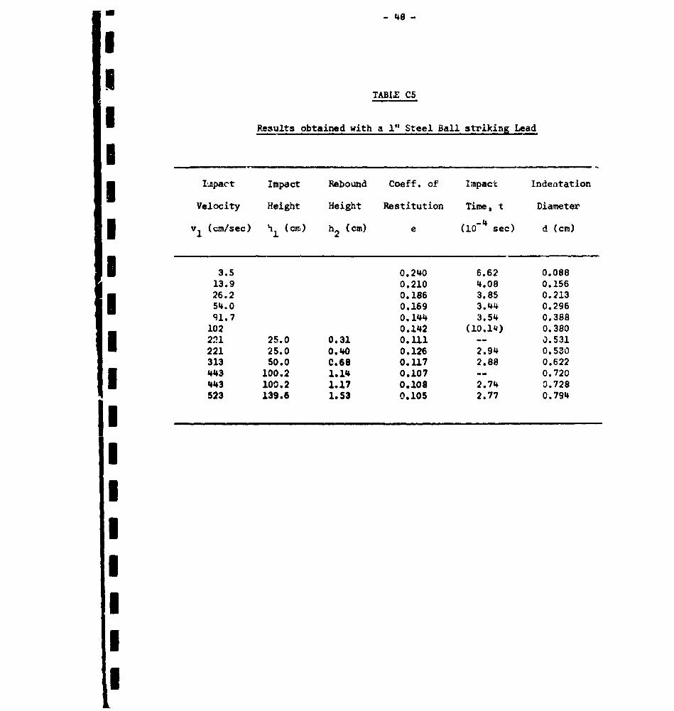
- 49 -
TABLE C6
Results obtained with a 1/2" Steel Ball Striking Le-d
Impact Impact Rebound Coeff. of Impact Indentation
Velocity Height Height Restitution Time, t Diameter
v (cm/sec) h (cm) h2 (cm) e (10-. sec) d (cm)
2.67 0.272 3.66 0.03730.2 3.182 2.00 0.115
105 (0.087) 1.75 0.194221 25 0.39 0.125 -- 0.264313 50 0.79 0.126 1.40 0.308313 50 0.70 0.118 -- 0.313313 50 0.70 01118 -- 0.313524 140 1.70 0.1.10 1.37 0.390
- 50 -
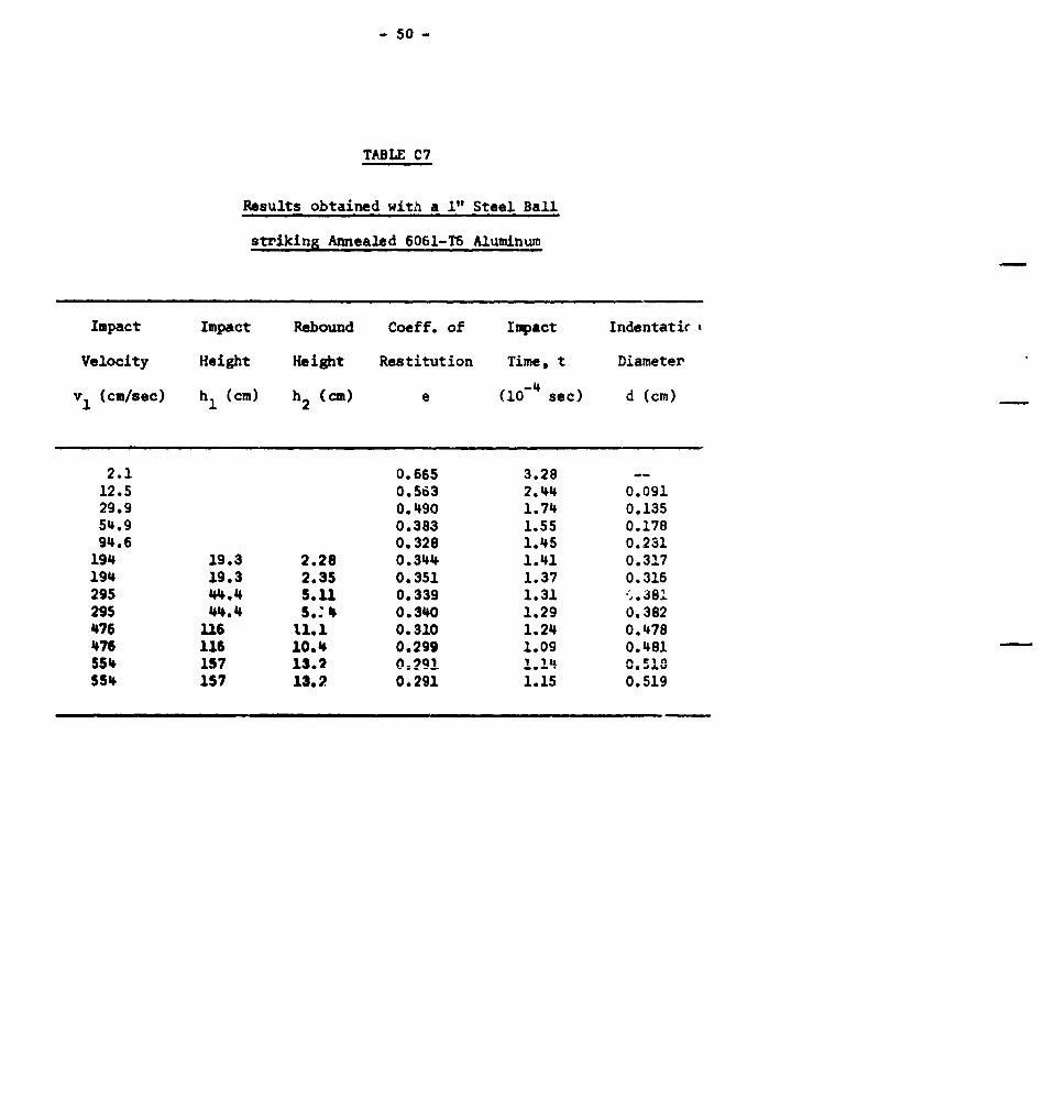
TABLE C7
Results obtained with a I" Steel Ball
striking Annealed 6061-T6 Aluminum
Impact Impact Rebound Coeff. of Impact Indentatic',
Velocity Height Height Restitution Time, t Diameter
V1 (cm/sec) hI (cm) h 2 (cm) e (10-4 sec) d (cm)
2.1 0.665 3.28 --12 .5 0.563 2.44 0.09129o9 0.490 1.74 0.13554.9 0.383 1.55 0.17894.6 0.328 1.45 0.231
194 19.3 2.28 0.344 1.41 0.317194 19.3 2.35 0.351 1.37 0.316295 44.4 5.11 0.339 1.31 ý,.381295 44.4 S." 4 0.340 1.29 0.382476 116 11.1 0.310 1.24 0.478476 116 10.14 0.299 1.09 0.481554 157 13.2 oz.9Q i.q W , .S10554 157 13.2 0.291 1.15 0.519
- 51 -
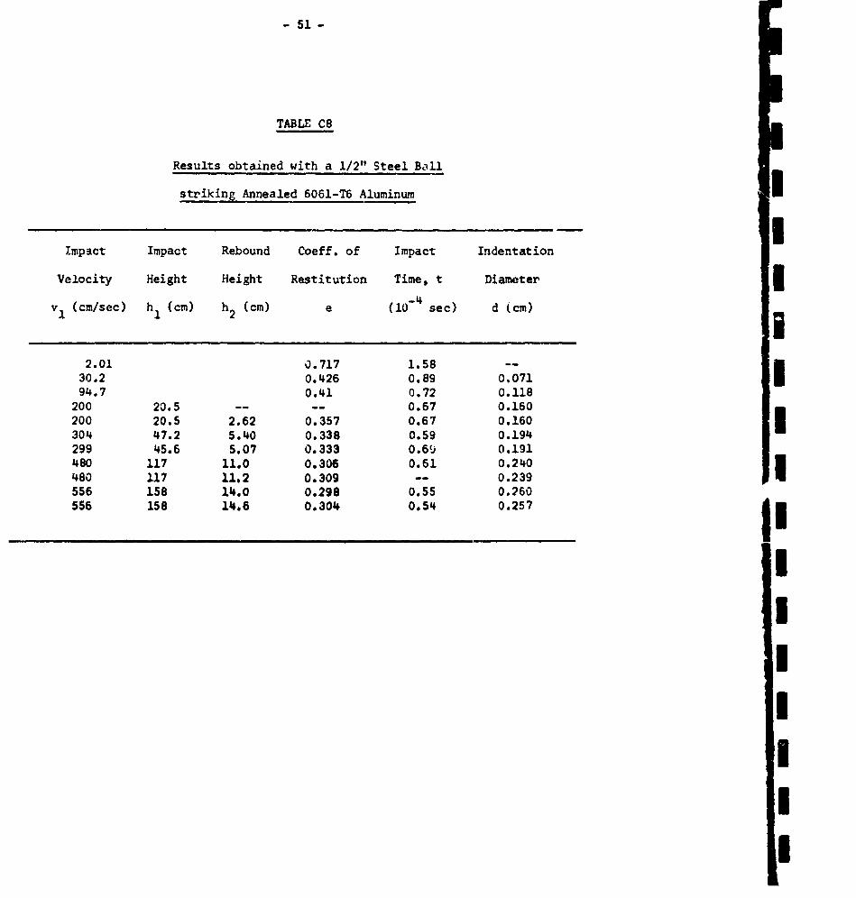
TABLE C8
Results obtained with a 1/2"1 Steel Ball
striking Annealed 6061-T6 Aluminum
Impact Impact Rebound Coeff. of Impact Indentation
Velocity Height Height Restitution Time, t Diameter
vI (cm/sec) hI (cm) h2 (cm) e (10-4 sec) d (cm)
2.01 0.717 1.58 --
II30.2 0.426 0.89 0,07194.7 0.41 0.72 0.118
200 20.5 -- -- 0.67 0.160200 20.5 2.62 0.357 0.67 0.160I304 47.2 5.40 0.338 0.59 0.194299 45.6 5.07 0.333 0.69 0.191480 117 11.0 0.306 0.61 0.240480 117 11.2 0.309 -- 0.239 I556 158 14.0 0.298 0.55 0.260556 158 14.6 0.304 0.54 0.257
I-I:II
I,I|
- 52 -
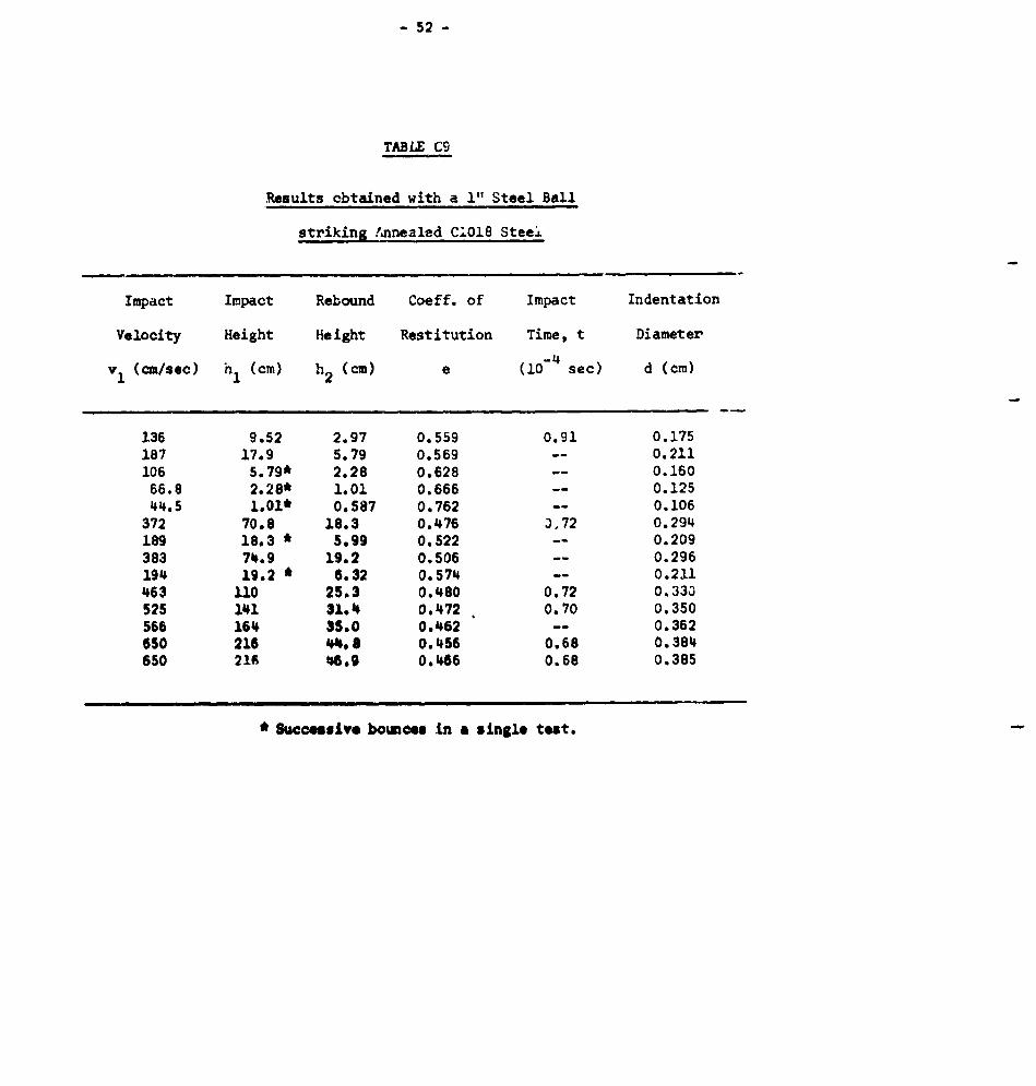
TABLE C9
Reaults obtained with a I" Steel Ball
striking Annealed C.018 Steel
Impact Impact Rebound Coeff. of Impact Indentation
Velocity Height Height Restitution Time, t Diameter
S(cm/sec) h (cm) h2 (cm) e (10-4 sec) d (cm)
136 9.52 2.97 0.559 0.91 0.175187 17.9 5.79 0.569 -- 0.211106 5.79* 2.28 0.628 -- 0.160
66.8 2.28* 1.01 0.666 -- 0.12544.5 1.01* 0.587 0.762 -- 0.106
372 70.8 18.3 0.476 3,72 0.294189 18.3 * 5.99 0.522 -- 0.209383 74.9 19.2 0.506 -- 0.296194 19.2 * 6.32 0.574 -- 0.211463 110 25.3 0.480 0.72 0.330525 141 31.4 0.472 0.70 0.350566 164 35.0 0.462 -- 0.362650 216 44.,8 0.456 0.68 0.384650 216 4609 0.466 0.68 0.385
* Successive bounces in a single test.
- 53 -
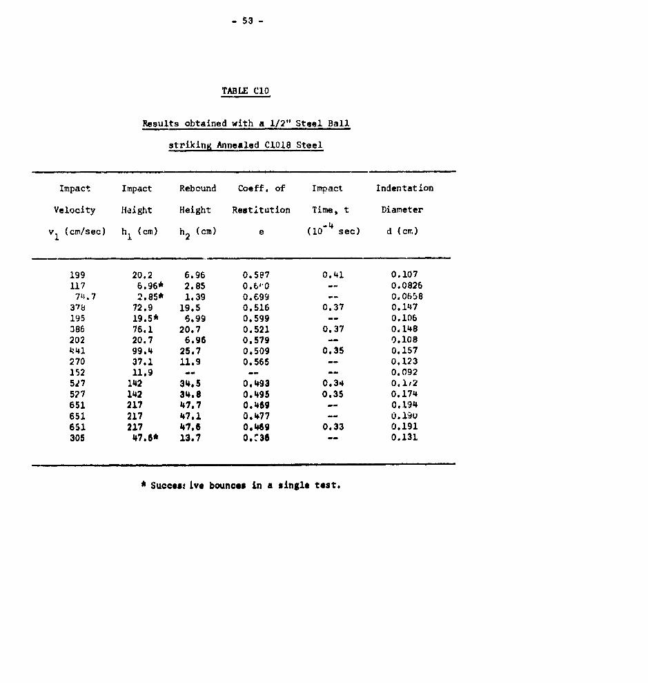
TABLE C10
Results obtained with a 1/2" Steel Ball
striking Annealed C1018 Steel
Impact Impact Rebound Coeff. of Impact Indentation
Velocity Height Height Restitution Time, t Diameter
(cm/sec) hI (cm) h2 (cm) e (10-4 sec) d (cm)
199 20.2 6.96 0.587 0.41 0.107117 6.96* 2.85 0.6"0 -- 0.082674.7 2.85* 1,39 0.699 -- 0.0658
378 72.9 19.5 0.516 0.37 0.147195 19.5* 6.99 0.599 -- 0.106386 76.1 20.7 0.521 0.37 0.148202 20.7 6.96 0,579 -- 0.108441 99.4 25.7 0.509 0.35 0.157270 37.1 11.9 0.565 -- 0.123152 11.9 ....-- 0.092527 142 34.5 0.493 0.34 0.1,2527 142 34.8 0.495 0.35 0.174651 217 47.7 0.469 -- 0.194651 217 47.1 0.477 -- O.1io651 217 47.6 0.469 0.33 0.191305 47.6* 13.7 0.M36 -- 0.131
* Success Lve bounces Ln a single test.
- 514 -
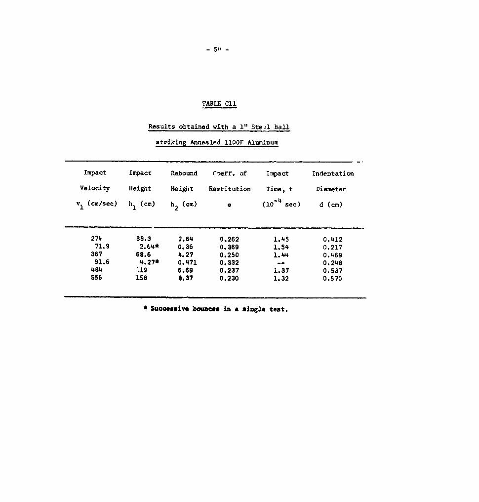
7ABLE Cl1
Results obtained with a 1" SteAl Ball
striking Annealed 110OF Aluminum
Impact Impact Rebound C-,eff. of Impact Indentation
Velocity Height Height Restitution Time, t Diameter
v1 (cm/sec) h (cm) h2 (cm) e (10-4 sec) d (cm)
274 38.3 2.64 0.262 1.45 0.41271.9 2.64* 0.36 0.369 1.54 0.217
367 68.6 4.27 0.250 1.44 0.46991.6 14.27* 0.471 0.332 -- 0.248484 U19 6.69 0.237 1.37 0.537556 158 8.37 0.230 1.32 0.570
* Successive bounces in a single test.
- 55 -
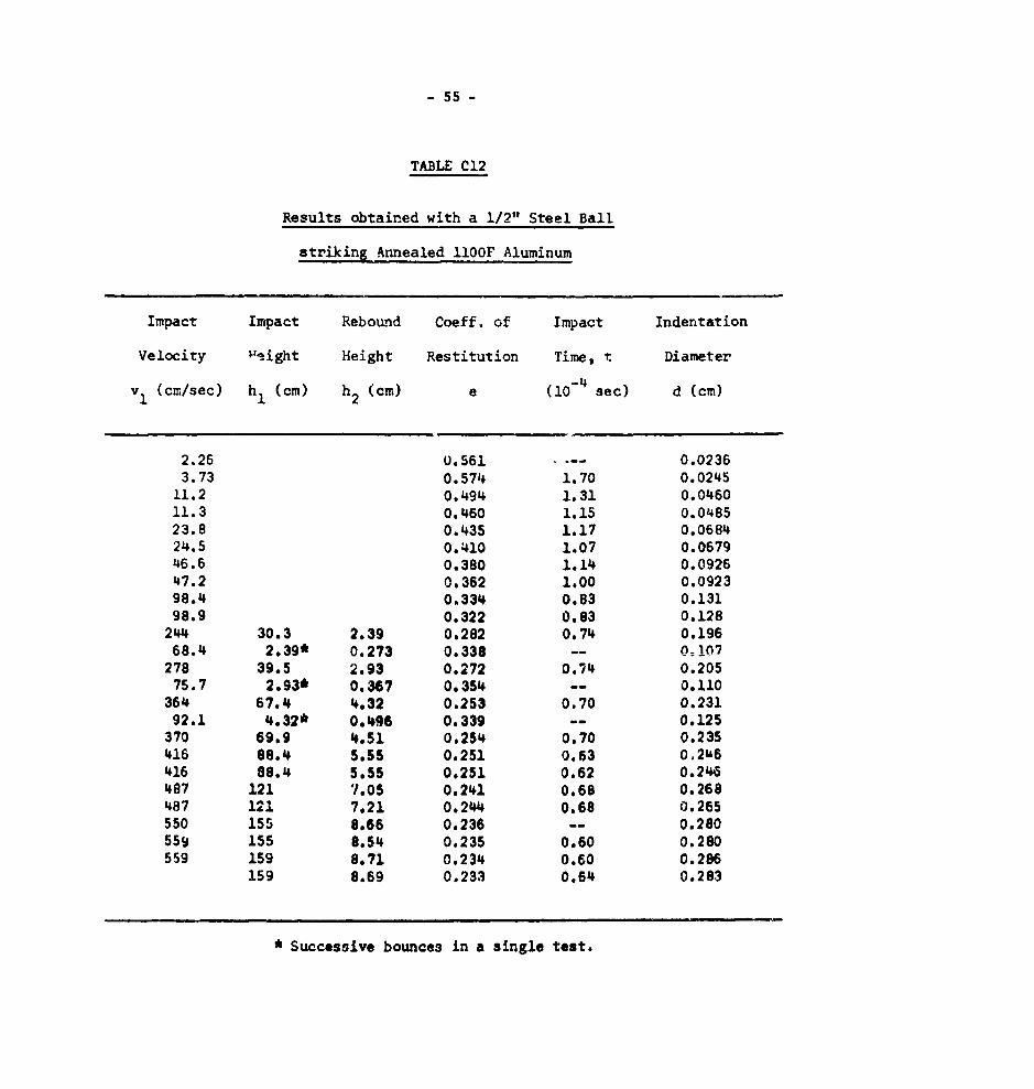
TABLE C12
Results obtained with a 1/2" Steel Ball
striking Annealed 110OF Aluminum
Impact Impact Rebound Coeff. of Impact Indentation
Velocity weight Height Restitution Time, t Diameter
vI (cm/sec) hI (cm) h2 (cm) e (i0-4 sec) d (cm)
2.26 0.561 - 0.02363.73 0.574 1.70 0.0245
11.2 0.494 1.31 0.046011.3 0.460 1.15 0.048523.8 0.435 1.17 0.068424.5 0.410 1.07 0.067946.6 0.380 1.14 0.092647.2 0.362 1.00 0.092398.4 0.334 0.83 0.13198.9 0.322 0.83 0.128
244 30.3 2.39 0.282 0.74 0.19668.4 2.39* 0.273 0.338 -- 0=1n7
278 39.5 2.93 0.272 0.74 0.20575.7 2.93* 0.367 0.354 -- 0.110
364 67.4 4.32 0.253 0.70 0.23192.1 4.32* 0.496 0.339 -- 0.125
370 69.9 4.51 0.254 0.70 0.235416 88.4 5.55 0.251 0.63 0,2U6416 88.4 5.55 0.251 0.62 0.246487 121 '.05 0.241 0.68 0.268487 121 7.21 0.244 0.68 0.265550 155 8.66 0.236 -- 0.280559 155 8.54 0.235 0.60 0.280559 159 8.71 0.234 0.60 0.286
159 8.69 0.233 0.64 0.283
* Successive bounces in a single test.


![A MODEL OF ENHANCED STRAIN RATE SENSITIVITY IN ...2 A.G. Sheinerman and S.V. Bobylev metals have been suggested. Prasad and Armstrong [17] suggested that strain rate sensitivity is](https://static.fdocuments.net/doc/165x107/60bf5ee16240a414c6338d3f/a-model-of-enhanced-strain-rate-sensitivity-in-2-ag-sheinerman-and-sv-bobylev.jpg)