The Dulles Corridor Metrorail Project- Extension to Dulles ... TO DULLES INTERNATIONAL AIRPORT AND...
15
564 THE DULLES CORRIDOR METRORAIL PROJECT— EXTENSION TO DULLES INTERNATIONAL AIRPORT AND ITS TUNNELING ASPECTS J. Rudolf Bechtel Infrastructure Corp. V. Gall Gall Zeidler Consultants, LLC ABSTRACT The Virginia Department of Rail and Public Transportation and the Metropolitan Washington Airports Authority are undertaking the extension of Washington Metropoli- tan Area Transit Authority’s Metrorail service to Washington Dulles International Airport and beyond to Route 772 in Loudoun County, Virginia. The roughly 37 kilometers long, double track alignment involves two 700 meters long single track, soft ground NATM tunnels at Tysons Corner, two 3.3 kilometers long single track rock TBM tunnels at Dulles Airport and one 25-meter deep station at the airport to be constructed by NATM in sedimentary rock. The design-build project is being implemented in a Public-Private- Partnership. A joint venture of Bechtel and Washington Group International has con- cluded the preliminary engineering and construction is scheduled to start in late 2007. INTRODUCTION The Dulles Corridor Metrorail Project will extend Washington Metropolitan Area Transit Authority’s (WMATA) rail services from the Metrorail Orange Line in Fairfax County, Virginia to Route 772 near Ashburn in eastern Loudoun County, Virginia. This corridor encompasses several activity centers including Tysons Corner, Reston, Hern- don, and International Airport Dulles (IAD) as well as emerging activity centers in east- ern Loudoun County. The proposed project alignment within the Dulles Corridor is displayed in Figure 1. Rapid Transit for the Dulles Corridor was initially explored in the 1950s as part of the planning process for Dulles Airport. At that time it was decided to reserve the median of the Dulles Airport Access Highway for future transit access to the airport. Preservation of this median allows the alignment to be at grade for most of its length within the corridor. Since the initial planning, the need for transit in the Dulles Corridor had been studied and although rail transit in the corridor was not part of WMATA’s orig- inally adopted rapid transit system, rapid transit service for the corridor remained a local and regional goal (Schrag, 2006). The strong growth of the activity centers within the corridor in particular during the1990s and 2000s that continues today has led to momentum for Metrorail in the Dulles Corridor. Current and projected, regional growth data exemplify the need for rapid transit and its timely implementation (Dulles Transit Partners, 2006): Tysons Corner is the largest employment center in Virginia with 115,000 jobs and close to 4 million square meters of commercial space. Reston/Herndon is home of 70,000 jobs and 2.7 million square meters of com- mercial space.
Transcript of The Dulles Corridor Metrorail Project- Extension to Dulles ... TO DULLES INTERNATIONAL AIRPORT AND...
564
THE DULLES CORRIDOR METRORAIL PROJECT—EXTENSION TO DULLES INTERNATIONAL AIRPORT
AND ITS TUNNELING ASPECTS
J. RudolfBechtel Infrastructure Corp.
V. GallGall Zeidler Consultants, LLC
ABSTRACT
The Virginia Department of Rail and Public Transportation and the MetropolitanWashington Airports Authority are undertaking the extension of Washington Metropoli-tan Area Transit Authority’s Metrorail service to Washington Dulles International Airportand beyond to Route 772 in Loudoun County, Virginia. The roughly 37 kilometers long,double track alignment involves two 700 meters long single track, soft ground NATMtunnels at Tysons Corner, two 3.3 kilometers long single track rock TBM tunnels atDulles Airport and one 25-meter deep station at the airport to be constructed by NATMin sedimentary rock. The design-build project is being implemented in a Public-Private-Partnership. A joint venture of Bechtel and Washington Group International has con-cluded the preliminary engineering and construction is scheduled to start in late 2007.
INTRODUCTION
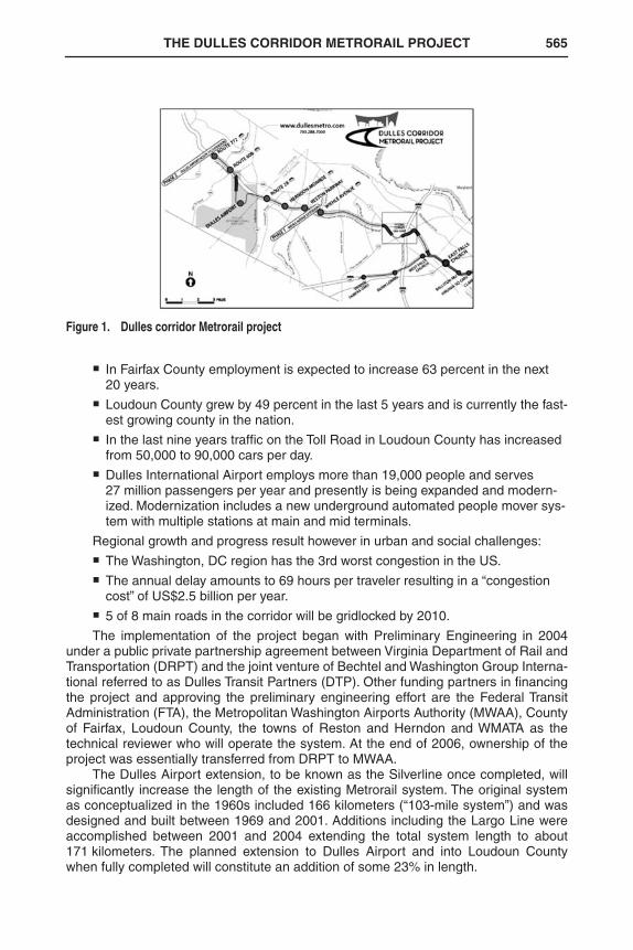
The Dulles Corridor Metrorail Project will extend Washington Metropolitan AreaTransit Authority’s (WMATA) rail services from the Metrorail Orange Line in FairfaxCounty, Virginia to Route 772 near Ashburn in eastern Loudoun County, Virginia. Thiscorridor encompasses several activity centers including Tysons Corner, Reston, Hern-don, and International Airport Dulles (IAD) as well as emerging activity centers in east-ern Loudoun County. The proposed project alignment within the Dulles Corridor isdisplayed in Figure 1.
Rapid Transit for the Dulles Corridor was initially explored in the 1950s as part ofthe planning process for Dulles Airport. At that time it was decided to reserve themedian of the Dulles Airport Access Highway for future transit access to the airport.Preservation of this median allows the alignment to be at grade for most of its lengthwithin the corridor. Since the initial planning, the need for transit in the Dulles Corridorhad been studied and although rail transit in the corridor was not part of WMATA’s orig-inally adopted rapid transit system, rapid transit service for the corridor remained alocal and regional goal (Schrag, 2006).
The strong growth of the activity centers within the corridor in particular duringthe1990s and 2000s that continues today has led to momentum for Metrorail in theDulles Corridor. Current and projected, regional growth data exemplify the need forrapid transit and its timely implementation (Dulles Transit Partners, 2006):
� Tysons Corner is the largest employment center in Virginia with 115,000 jobs and close to 4 million square meters of commercial space.
� Reston/Herndon is home of 70,000 jobs and 2.7 million square meters of com-mercial space.
RETC2007.bk Page 564 Thursday, April 19, 2007 1:48 PM
THE DULLES CORRIDOR METRORAIL PROJECT 565
� In Fairfax County employment is expected to increase 63 percent in the next 20 years.
� Loudoun County grew by 49 percent in the last 5 years and is currently the fast-est growing county in the nation.
� In the last nine years traffic on the Toll Road in Loudoun County has increased from 50,000 to 90,000 cars per day.
� Dulles International Airport employs more than 19,000 people and serves 27 million passengers per year and presently is being expanded and modern-ized. Modernization includes a new underground automated people mover sys-tem with multiple stations at main and mid terminals.
Regional growth and progress result however in urban and social challenges:
� The Washington, DC region has the 3rd worst congestion in the US.
� The annual delay amounts to 69 hours per traveler resulting in a “congestion cost” of US$2.5 billion per year.
� 5 of 8 main roads in the corridor will be gridlocked by 2010.
The implementation of the project began with Preliminary Engineering in 2004under a public private partnership agreement between Virginia Department of Rail andTransportation (DRPT) and the joint venture of Bechtel and Washington Group Interna-tional referred to as Dulles Transit Partners (DTP). Other funding partners in financingthe project and approving the preliminary engineering effort are the Federal TransitAdministration (FTA), the Metropolitan Washington Airports Authority (MWAA), Countyof Fairfax, Loudoun County, the towns of Reston and Herndon and WMATA as thetechnical reviewer who will operate the system. At the end of 2006, ownership of theproject was essentially transferred from DRPT to MWAA.
The Dulles Airport extension, to be known as the Silverline once completed, willsignificantly increase the length of the existing Metrorail system. The original systemas conceptualized in the 1960s included 166 kilometers (“103-mile system”) and wasdesigned and built between 1969 and 2001. Additions including the Largo Line wereaccomplished between 2001 and 2004 extending the total system length to about171 kilometers. The planned extension to Dulles Airport and into Loudoun Countywhen fully completed will constitute an addition of some 23% in length.
Figure 1. Dulles corridor Metrorail project
RETC2007.bk Page 565 Thursday, April 19, 2007 1:48 PM
566 2007 RETC PROCEEDINGS
WMATA METRORAIL SYSTEM AND TUNNELING EXPERIENCE
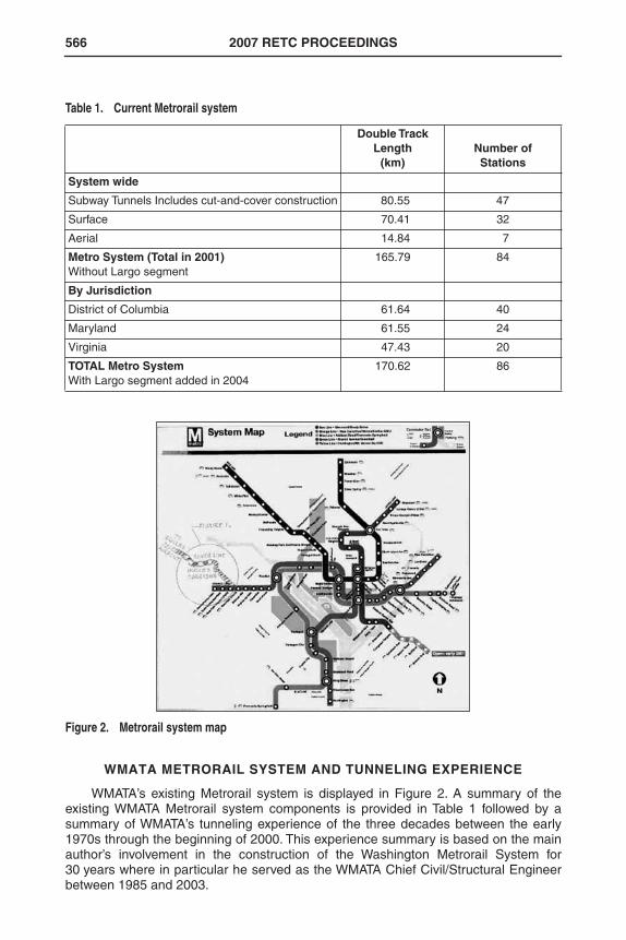
WMATA’s existing Metrorail system is displayed in Figure 2. A summary of theexisting WMATA Metrorail system components is provided in Table 1 followed by asummary of WMATA’s tunneling experience of the three decades between the early1970s through the beginning of 2000. This experience summary is based on the mainauthor’s involvement in the construction of the Washington Metrorail System for30 years where in particular he served as the WMATA Chief Civil/Structural Engineerbetween 1985 and 2003.
Table 1. Current Metrorail system
Double TrackLength
(km)Number of Stations
System wide
Subway Tunnels Includes cut-and-cover construction 80.55 47
Surface 70.41 32
Aerial 14.84 7
Metro System (Total in 2001)Without Largo segment
165.79 84
By Jurisdiction
District of Columbia 61.64 40
Maryland 61.55 24
Virginia 47.43 20
TOTAL Metro SystemWith Largo segment added in 2004
170.62 86
Figure 2. Metrorail system map
RETC2007.bk Page 566 Thursday, April 19, 2007 1:48 PM
THE DULLES CORRIDOR METRORAIL PROJECT 567
Tunneling Experience
WMATA’s more than 80 Kilometers of subway construction provides many exam-ples of tunneling methods and types of tunnel construction and displays a continuousdevelopment of tunnel design and construction methodology spanning some 30 years.
In the 1970s WMATA had employed tunneling methods nowadays considered an“old-standard.” Soft ground methods involved mandatory dewatering for tunneling withopen face digger shields, breasting and temporary support by steel ribs and lagging.These soft ground tunnels were designed for loading conditions assuming a loadequivalent to full overburden. Consequently, the final tunnel lining was a rigid, heavilyreinforced cast-in-place concrete structure with PVC waterstops in contraction jointsas the only means of positive waterproofing. Such construction was used on the InnerCity A-Redline, D-Orangeline, and Outer G-Blueline. During that time there are exam-ples of utilizing cast iron bolted segmental linings with lead waterproofed jointsbetween the liner segments. Cast iron linings were used for the Potomac River Tunnelon the C-Orangeline and the Waterfront Tunnel on the F-Greenline. Immersed(“sunken”) tube construction was used across the Washington Channel leading towardthe bridge across the Potomac River (L-Yellowline to Virginia).
For tunneling in rock, drill-and-blast methods were used for excavation with steelribs and cribbing as temporary support followed by cast-in-place reinforced concretefor final tunnel support. During this period WMATA already used a modern, gripper-type rock TBM when good bedrock conditions were present, with cast-in-place rein-forced concrete lining as final tunnel support. An example of such TBM tunneling isone section on the A-Redline. For the construction of a large, approximately 20-meterwide and 16-meter high mined station vault in rock, drill-and-blast methods were usedfor excavation. First, a pilot tunnel was employed in the crown followed by mining of amultiple drift cavern excavation. Support was by heavy rock bolting and massive steelribs embedded in shotcrete for both temporary and permanent support. The final struc-ture was established as an independent architectural segmental, pre-cast concretestructure erected within the mined vault. For the design of the permanent support inrock some arching effect was considered. Tunnel construction on the A-Redline underConnecticut and Wisconsin Avenues features examples of such rock tunneling to con-struct station vaults.
In the 1980s soft ground tunneling was accomplished using sophisticated EarthPressure Balance Machines (EPBM) with a single pass segmental, pre-cast concretelining with gaskets, both fabricated with tight tolerances. The tunneling was performedunder the Anacostia River in adverse ground conditions with about a 3-bar hydrostaticpressure. A very successfully waterproofed tunnel was achieved largely as a result ofwell-designed and tight tolerances that were required for segment construction andgasket fabrication. A finger type shape, dense (closed cell), neoprene gasket wasdeveloped and tested during construction. This EPBM tunneling was used also on twodifferent sections under M Street, namely Sections F3a and F3c on the Greenline.Even in most difficult conditions as under the Anacostia River tunneling was success-fully completed with no water leaks through the joints, which are still dry after over20 years in service. Dry tunnel conditions depended on a proper design and tight toler-ances of the pre-cast concrete segmental lining and the gaskets, including appropriatetesting that was explicitly specified. Successful installation of bolted segments with ahard gasket depends on having appropriate ring erection equipment and on contactgrouting within the time specified to avoid squatting and misalignment (see Consider-ations for One-Pass Tunnel Lining Design Under High Hydrostatic Pressure). The con-tractor experienced difficulty in closing the rings due to lack of an erector ring offeredby the machine manufacturer, however the final result thanks to every ones effort wasa successfully constructed and watertight tunnel.
RETC2007.bk Page 567 Thursday, April 19, 2007 1:48 PM
568 2007 RETC PROCEEDINGS
On other Metro sections open face TBM tunneling was utilized. On one section witha low hydrostatic pressure compressed air was employed to control ground water inflow.On another section with an open face TBM systematic dewatering was performed. Bothopen face TBM drives utilized a one-pass segmental, gasketed, pre-cast concrete liningwhich also was successfully installed and remained fairly dry after construction. Afterextensive material testing soft gaskets were used for these applications.
Also in the 1980s WMATA allowed new, at that time progressive, tunneling andwaterproofing approaches. Consequently, in 1984 WMATA accepted the use of NATMrock tunneling proposed by the contractor in a Value Engineering Change Proposal(VECP) framework. This was the first application of a dual lining NATM system withPVC waterproofing in the US. It was utilized for running tunnels and station construc-tion on the B-Redline to Wheaton, MD. The design considered arching of the surround-ing ground and interaction between ground and the initial lining. Un-reinforced, cast-in-place concrete lining was used for final support. The design was conducted utilizingthe German DIN Code, as the ACI Code had no provision in this application for plain(un-reinforced) concrete. Tunnel and station waterproofing was by an “umbrella type”PVC membrane with fully immersed sidewall drains located in the invert and on bothsides of the tunnel arch. This system resulted in completely dry tunnels and station incontrast to the A-Redline rock tunnels experiencing persistent leaks. At the end of the1980s and at the beginning of the 1990s NATM tunneling was used again, but this timein soft ground conditions for running tunnels and complicated split station vault con-struction at Fort Totten on the Greenline. The Fort Totten station of Section E5a wasbuilt using five different drifts. The first center drift was excavated for the installation ofa column line located in the middle of the future station platform. A heavy pre-supportby 25-meter long secant jet grouted piles installed from the portal wall to form a crownarch was specified. This roof pre-support was to be followed with overlapping forepol-ing sheets. In lieu of the jet grouted arch the contractor provided a heavy temporaryportal wall and used soil stabilization by micro-fine cement grouting in combinationwith overlapping sheeting driven above lattice girders using a hydraulic ram. Both, thestation and adjacent NATM running tunnels were fully encased by a PVC membranefor waterproofing.
Soft ground NATM tunneling was used again in the mid-1990s to create the con-nection to the Fort Totten Station. This involved tunneling under the historic RockCreek Cemetery by employing dewatering from inside the tunnel using vacuum lances,since access to the cemetery was excluded for construction purposes. A grouted archas a crown pre-support was used to control surface settlements. The grouted pipeswere installed by “directional drilling” methods for approximately 250 meters under theRock Creek Cemetery from a shaft at New Hampshire Avenue. The tunneling opera-tion and the results were very successful, limiting surface settlements to below 1.5 cm.This section E4b was part of the Mid-City E-Greenline.
Also in the 1990s WMATA adopted a cost effective “Two-Pass” lining system forthe circular soft ground tunnels excavated by the open face digger shield method intro-duced by contractors through a VECP on the Outer E-Greenline tunnels (Sections E6eand E8a) which were originally designed and specified for TBM tunneling with a singlepass lining and for NATM mined tunneling, respectively.
The two-pass lining system consist of 1.2 meter wide and typically 23 cm thick ini-tial pre-cast reinforced concrete lining segments that form a ring installed within theshield tail which is then shoved out of the tail. The ring is then expanded against theground using 100-ton capacity jacks at 10 and 2 o’clock locations. After expansion isachieved, steel struts (“Dutchman”) are inserted and grouted in place to form the struc-tural initial lining ring. Once the tunnel opening was supported by the initial lining and
RETC2007.bk Page 568 Thursday, April 19, 2007 1:48 PM
THE DULLES CORRIDOR METRORAIL PROJECT 569
monitoring indicated acceptable ring stability, PVC waterproofing membrane installa-tion followed fully encasing the tunnel. Subsequently, a plain, cast-in-place final liningis installed, typically 42 cm thick.
Apart from the need for dewatering, the digger shield method also required theuse of ground modification techniques such as chemical grouting applied systemati-cally from the surface prior to tunneling. Examples are the 14th Street tunnels and theunder/over tunnels at Park Road, both part of the Mid-City E-Greenline in Washington,DC. Construction of these tunnels started in 1994. The roughly 35 meter deep under/over tunnels were first partially dewatered following the owner’s designed drawdownsystem using deep wells. This system was only partially effective above the tunnelinvert and was followed by an extensive chemical grouting program using sodium sili-cate to stabilize mainly sandy ground that existed across the tunnel profile and abovethe tunnels. Following this grouting program, although costly, tunneling was accom-plished very successfully in this urban setting.
The design of the two-pass lining system utilizing an expanded pre-cast initial linerin soft ground at that time generally assumed the initial liner to be sacrificial or “throw-away” and temporary in nature. However, WMATA changed the design philosophy andaccounted for the structural capacity of the initial lining in the design of the final liningsupport system. The premise for this assumption and adaptation of design philosophywas that the initial support created a solid, closed concrete ring. This consequentlyexcluded the use of wooden wedges between segments. Further, the pre-cast liningwas required to be fully stabilized before the final concrete lining was cast in place. Thefinal liner was designed taking the combined support of both liners into consideration.Using soil-structure interaction and assuming flexibility of the initial lining the linerswere designed for “Short Term Loading” and all WMATA loading combinations includ-ing full hydrostatic pressure acting on the final lining for “Long Term Loading.” Usingthese assumptions the initial pre-cast and the final cast-in-place linings share the long-term loading combination. This allowed the use of an un-reinforced, cast-in-place finalconcrete lining. For the initial liner segments installed as expanded rings, successdepended upon dewatering, chemical pre-grouting, and immediate expansion by jack-ing of the segments against the ground.
Depending on the nature of the soils, the ground water level and the difficulty indewatering, such as from aquifers of artesian nature, it was necessary to use EPBMtechnology again. In such instance the initial liner was of a non-expansion type, con-sisting of lightly bolted segments similar to those in single-pass installations but withtemporary, soft gaskets designed for partially dewatered conditions. Upon initial lininginstallation, a PVC waterproofing system was installed followed by an un-reinforcedcast-in-place concrete lining. This method was referred to as “Modified Two-Pass” sys-tem. Such systems were used on the Outer F-Greenline, Sections F6a and F6c atSuitland Parkway Line to Branch Avenue. Here, the two-pass lining system was usedfor the first time with the EPBM tunneling method on the WMATA system. In this appli-cation the usual rings of four (4) reinforced concrete segments with a key segment areonly lightly bolted in the longitudinal joints. Sponge type gaskets in joints and the initialliner are designed for temporary hydrostatic pressure as the final waterproofing isachieved by the PVC membrane installed around the entire lining circumference. Thissystem is obviously more costly, but was necessary to overcome the most adverseground and water conditions where full dewatering was not allowed due to environ-mental concerns. For the initial lining installation success depended upon water con-trol, proper erection systems, and accomplishing contact grouting immediately behinda sealed tail of the TBM shield (Rudolf, 1997).
RETC2007.bk Page 569 Thursday, April 19, 2007 1:48 PM
570 2007 RETC PROCEEDINGS
Considerations for One-Pass Tunnel Lining Design Under High Hydrostatic Pressure
From the lessons learned on the WMATA system in the past three decades a num-ber of important considerations for the design of one-pass tunnel linings for soft groundunder high hydrostatic pressure can be derived. These are equally applicable to design-bid-build and design-build type project delivery methods and applicable regardlesswhether the specifications are of a method or performance type and summarized below.
Segment Considerations. Apart from proper selection of segment geometry withregard to the shape (rectangular or trapezoidal), the number of segments in a ring withkey segments at crown level, tapering and thickness, adequate strength for groundand construction loadings leading to segment thickness and being able to accommo-date gasket pockets, grooves, bolts and packing materials it is important to:
� Specify tight tolerances for segments and very tight tolerances for gasket pock-ets. The British Tunneling Society’s recommendations for tolerances for the fab-rications of special segments are suggested (British Tunneling Society, 2000).
� For pre-cast concrete segments specify high strength and high performance concrete, typically 42 MPa (6,000 psi) to 50 MPa (7,000 psi) concrete reinforced to withstand temporary and long-term loadings and appropriate loading combi-nations depending on type of soil and overburden as well as construction load-ing from longitudinal and circumferential forces including handling and bolting.
� To assure a high quality product and the tunnel’s longevity all aspects of the fabrica-tion and installation must be rigorously controlled prior to and during construction.
Gaskets and Packing Considerations
� Select a high quality gasket material with high permanent resilience (stress relaxation) and specify a thorough material testing. Note that the “finger shaped,” closed cell-hard 17⁄8" wide neoprene gasket and 30-mil neoprene pack-ing on each segment are still performing well in the Anacostia River Tunnel, although the industry nowadays prefers EPDM materials.
� Specify minimum gasket width considering possible segment offset due to installation. A width of 45 millimeters (13⁄4") is preferred for a 13 millimeter (0.5") offset. To prevent overfill specify that for any condition the total cross sectional area of a “hard” gasket shall not exceed 95% of the total area of the pocket between segments, calculated when the faces of the segments (including the neoprene packers) are in a full contact.
� Specify a Minimum Working Pressure (hydrostatic pressure × safety factor) and a Maximum Pressure to fully compress the gasket in the confined pocket. For the Anacostia River Tunnel the working pressure was 1.4 MPa (200 psi) and the maximum pressure was 2.8 MPa (400 psi).
Liner and Gasket System Testing
� Specify Stability Testing for water tightness to withstand the minimum working pressure without leaks.
� Specify Load Deflection Testing to measure force closure required to fully com-press the gasket confined in the pocket.
Note that prior to the design of the first single-pass WMATA tunnel with reinforcedconcrete pre-cast segmental tunnel linings an extensive testing of segments for strengthin conjunction with the gaskets was performed by Prof. S.L. Paul for WMATA’s GeneralEngineering Consultant, DeLeuw, Cather and Company (Paul, 1978 and 1984).
RETC2007.bk Page 570 Thursday, April 19, 2007 1:48 PM
THE DULLES CORRIDOR METRORAIL PROJECT 571
It is recommended that a few gaskets be pre-fabricated to the detailed dimensionswith minimum and maximum tolerances. Both types should be tested in the specifiedpockets (between steel plates separated by packing). This should be done in a labora-tory environment similar to the Stress Relaxation Test. These requirements should bespecified to verify minimum and maximum compression pressures.
These tests carried out in a laboratory environment should determine the maxi-mum and minimum pressures obtained for the extreme values of specified tolerancesso they are not exceeded in either direction. The larger gasket, i.e., maximum toler-ance, should be placed in the smallest pocket with the minimum tolerance and loadtested by a Load Deflection Test to verify the maximum pressure at closure. The gasketwith the minimum tolerance shall be placed in the largest pocket with the maximum tol-erance and tested for leakage by a Leak Test performed by squeezing to closure at theminimum pressure specified. This test shall include the compression packing material.This test should further consider an offset of 10 millimeters (0.4") to 13 millimeters(0.5") in horizontal direction.
Erection of Ring and Segment Bolting Considerations
� The lining erector shall be composed of a full erector ring and erector arm capa-ble of squeezing the gaskets with a packer in the gap between segment faces without fully relying on bolts. The segments and erection ring and erection arm must be compatible with the TBM and the liner system to ensure safe and effi-cient segment installation and ring closing.
Contact Grouting Considerations
� Require immediate grouting behind the wire brush seal in the shield tail.
� Require grout sufficiently stiff to provide immediate passive reaction to limit liner ring squatting.
� Require full grouting of each ring after ejection from the shield tail before the next excavation cycle begins.
� Specify the allowed over excavation and maximum annular space between the outside surface of the segments and the excavated ground surface.
Other Considerations
� Require the contractor to lay out corrective methods due to misalignment which would involve bolting to the adjacent ring.
� Specify the allowed over excavation and maximum annular space between the outside surface of the segments and the excavated ground surface.
� Require a jacking ring or shoes with pads that will equally distribute the jacking force to the liner.
� Specify the maximum jacking force that can be applied to the liner without dam-aging it.
� Specify requirements for installation and instrumentation and monitoring.
These considerations and suggested requirements are to ensure that the contrac-tor can achieve the specified structural performance of the tunnel over its design lifeand beyond and in particular its water tightness without costly changes during con-struction and/or costly repairs and post construction grouting to restore the tunnelwater tightness. These also facilitate use of adequate construction techniques to pre-vent excessive ground loosening, development of voids, inadequate backfill grouting,and excessive liner distortion. Construction methods must facilitate a quick develop-ment of a passive reaction with the ground to limit displacement as otherwise the linercan distort beyond the design limit (Kaneshiro & Navin, 1996).
RETC2007.bk Page 571 Thursday, April 19, 2007 1:48 PM
572 2007 RETC PROCEEDINGS
DULLES CORRIDOR METRORAIL PROJECT
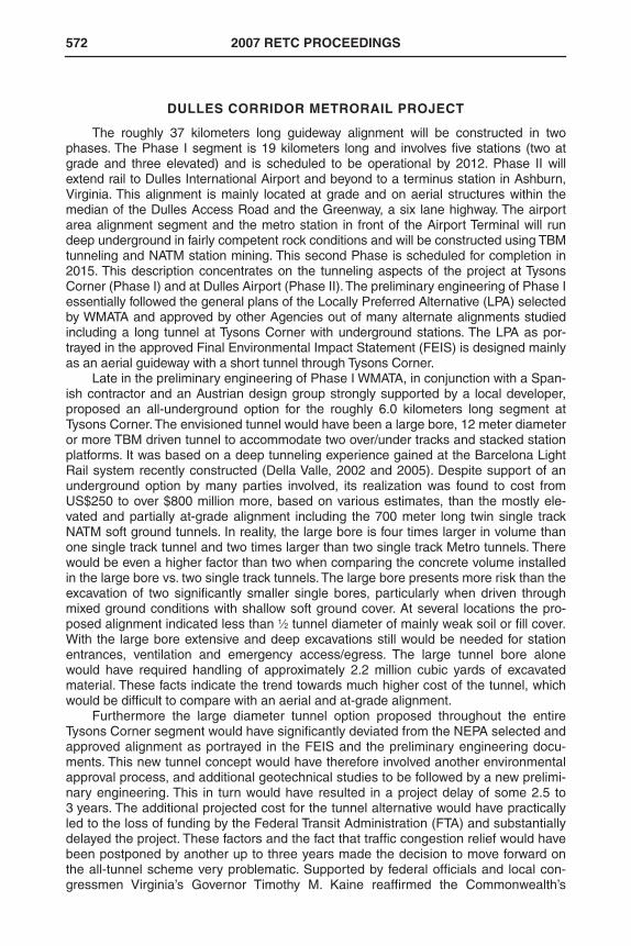
The roughly 37 kilometers long guideway alignment will be constructed in twophases. The Phase I segment is 19 kilometers long and involves five stations (two atgrade and three elevated) and is scheduled to be operational by 2012. Phase II willextend rail to Dulles International Airport and beyond to a terminus station in Ashburn,Virginia. This alignment is mainly located at grade and on aerial structures within themedian of the Dulles Access Road and the Greenway, a six lane highway. The airportarea alignment segment and the metro station in front of the Airport Terminal will rundeep underground in fairly competent rock conditions and will be constructed using TBMtunneling and NATM station mining. This second Phase is scheduled for completion in2015. This description concentrates on the tunneling aspects of the project at TysonsCorner (Phase I) and at Dulles Airport (Phase II). The preliminary engineering of Phase Iessentially followed the general plans of the Locally Preferred Alternative (LPA) selectedby WMATA and approved by other Agencies out of many alternate alignments studiedincluding a long tunnel at Tysons Corner with underground stations. The LPA as por-trayed in the approved Final Environmental Impact Statement (FEIS) is designed mainlyas an aerial guideway with a short tunnel through Tysons Corner.
Late in the preliminary engineering of Phase I WMATA, in conjunction with a Span-ish contractor and an Austrian design group strongly supported by a local developer,proposed an all-underground option for the roughly 6.0 kilometers long segment atTysons Corner. The envisioned tunnel would have been a large bore, 12 meter diameteror more TBM driven tunnel to accommodate two over/under tracks and stacked stationplatforms. It was based on a deep tunneling experience gained at the Barcelona LightRail system recently constructed (Della Valle, 2002 and 2005). Despite support of anunderground option by many parties involved, its realization was found to cost fromUS$250 to over $800 million more, based on various estimates, than the mostly ele-vated and partially at-grade alignment including the 700 meter long twin single trackNATM soft ground tunnels. In reality, the large bore is four times larger in volume thanone single track tunnel and two times larger than two single track Metro tunnels. Therewould be even a higher factor than two when comparing the concrete volume installedin the large bore vs. two single track tunnels. The large bore presents more risk than theexcavation of two significantly smaller single bores, particularly when driven throughmixed ground conditions with shallow soft ground cover. At several locations the pro-posed alignment indicated less than 1⁄2 tunnel diameter of mainly weak soil or fill cover.With the large bore extensive and deep excavations still would be needed for stationentrances, ventilation and emergency access/egress. The large tunnel bore alonewould have required handling of approximately 2.2 million cubic yards of excavatedmaterial. These facts indicate the trend towards much higher cost of the tunnel, whichwould be difficult to compare with an aerial and at-grade alignment.
Furthermore the large diameter tunnel option proposed throughout the entireTysons Corner segment would have significantly deviated from the NEPA selected andapproved alignment as portrayed in the FEIS and the preliminary engineering docu-ments. This new tunnel concept would have therefore involved another environmentalapproval process, and additional geotechnical studies to be followed by a new prelimi-nary engineering. This in turn would have resulted in a project delay of some 2.5 to3 years. The additional projected cost for the tunnel alternative would have practicallyled to the loss of funding by the Federal Transit Administration (FTA) and substantiallydelayed the project. These factors and the fact that traffic congestion relief would havebeen postponed by another up to three years made the decision to move forward onthe all-tunnel scheme very problematic. Supported by federal officials and local con-gressmen Virginia’s Governor Timothy M. Kaine reaffirmed the Commonwealth’s
RETC2007.bk Page 572 Thursday, April 19, 2007 1:48 PM
THE DULLES CORRIDOR METRORAIL PROJECT 573
selection of the aerial alignments through Tysons (MacGillis, 2006), and DTP resumeddesign work on the original Phase 1 project alignment.
Soft Ground NATM Tunneling for Phase I
The mined tunnel segment includes twin single track NATM tunnels at a length of700 meters each and an emergency cross-passage. Short cut-and-cover sections will beutilized at the portals. These tunnels will be constructed in soft ground and will be locatedadjacent to existing structures and utilities that are sensitive to ground movements.
The soils encountered along the tunnel alignment include mainly residual soilsand soil like, completely decomposed rock. The residual soils are the result of in-placeweathering of the underlying bedrock and are typically fine sandy silts and clays, andsilty fine sands. According to project classification the residual soils are identified asStratum S which can be divided into two substrata based on the consistency and thedegree of weathering. The upper substratum, S1, typically exhibits lower N-values(averaging 16 bpf or less) and has higher fines content. Typical USCS classificationsare ML, CL, and/or SM. Within the tunnel alignment, the thickness of substratum S1varies considerably, from 0–2 feet to almost 30 feet. The lower substratum, S2, is simi-lar to S1, but typically exhibits higher N-values (averaging 16 bph or greater) and ismade up of more granular particles. Its thickness within the tunnel alignment rangesfrom 4 feet to 60 feet. Substrata S1 and S2 will be the predominant soil types encoun-tered during tunnel construction with tunneling within the S1 stratum mainly near theportals and stratum S2 where the tunnel is located deeper in the mid portion of thealignment. Only to a limited extent where the tunnel is deepest will tunneling encounterdecomposed rock referred to as D1 in bench and invert. The decomposed rock is a soillike material but has higher blow counts with N-values between 60 bpf and 100 bpf.Ground water at portal locations is generally at invert elevation, in mid-point of the tun-nel alignment it rises up to the tunnel spring line.
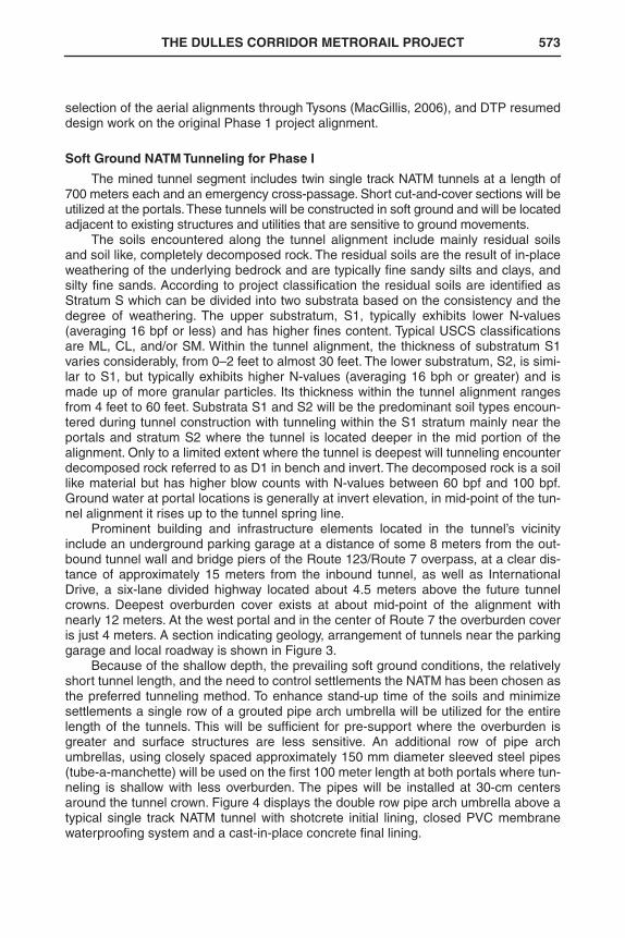
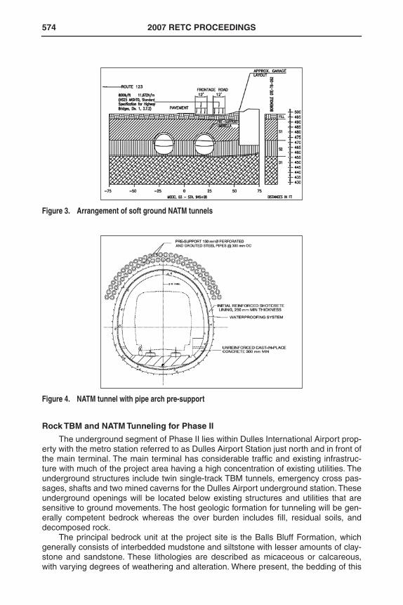
Prominent building and infrastructure elements located in the tunnel’s vicinityinclude an underground parking garage at a distance of some 8 meters from the out-bound tunnel wall and bridge piers of the Route 123/Route 7 overpass, at a clear dis-tance of approximately 15 meters from the inbound tunnel, as well as InternationalDrive, a six-lane divided highway located about 4.5 meters above the future tunnelcrowns. Deepest overburden cover exists at about mid-point of the alignment withnearly 12 meters. At the west portal and in the center of Route 7 the overburden coveris just 4 meters. A section indicating geology, arrangement of tunnels near the parkinggarage and local roadway is shown in Figure 3.
Because of the shallow depth, the prevailing soft ground conditions, the relativelyshort tunnel length, and the need to control settlements the NATM has been chosen asthe preferred tunneling method. To enhance stand-up time of the soils and minimizesettlements a single row of a grouted pipe arch umbrella will be utilized for the entirelength of the tunnels. This will be sufficient for pre-support where the overburden isgreater and surface structures are less sensitive. An additional row of pipe archumbrellas, using closely spaced approximately 150 mm diameter sleeved steel pipes(tube-a-manchette) will be used on the first 100 meter length at both portals where tun-neling is shallow with less overburden. The pipes will be installed at 30-cm centersaround the tunnel crown. Figure 4 displays the double row pipe arch umbrella above atypical single track NATM tunnel with shotcrete initial lining, closed PVC membranewaterproofing system and a cast-in-place concrete final lining.
RETC2007.bk Page 573 Thursday, April 19, 2007 1:48 PM
574 2007 RETC PROCEEDINGS
Rock TBM and NATM Tunneling for Phase II
The underground segment of Phase II lies within Dulles International Airport prop-erty with the metro station referred to as Dulles Airport Station just north and in front ofthe main terminal. The main terminal has considerable traffic and existing infrastruc-ture with much of the project area having a high concentration of existing utilities. Theunderground structures include twin single-track TBM tunnels, emergency cross pas-sages, shafts and two mined caverns for the Dulles Airport underground station. Theseunderground openings will be located below existing structures and utilities that aresensitive to ground movements. The host geologic formation for tunneling will be gen-erally competent bedrock whereas the over burden includes fill, residual soils, anddecomposed rock.
The principal bedrock unit at the project site is the Balls Bluff Formation, whichgenerally consists of interbedded mudstone and siltstone with lesser amounts of clay-stone and sandstone. These lithologies are described as micaceous or calcareous,with varying degrees of weathering and alteration. Where present, the bedding of this
Figure 3. Arrangement of soft ground NATM tunnels
Figure 4. NATM tunnel with pipe arch pre-support
RETC2007.bk Page 574 Thursday, April 19, 2007 1:48 PM
THE DULLES CORRIDOR METRORAIL PROJECT 575
formation is generally well developed, ranging from laminar (beds less than 15 mmthick) to medium bedded (beds from 20 cm to 60 cm thick).
The bedrock is occasionally to moderately jointed and the prevailing beddingplanes dip at an angle of about 15° to 30° to predominantly the west. Occasionalzones of highly fractured rock intercept the rock mass. While the siltstone bedrock rep-resents a favorable tunneling medium for both TBM and road header excavationground control and support measures have to account for the jointing and beddingplanes that, if left unsupported, may develop blocks and wedges with the tendency tofall-out or slide into the excavation.
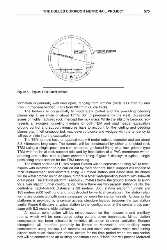
The TBM tunnels have an approximately 6 meter outside diameter and are about3.3 kilometers long each. The tunnels will be constructed by either a shielded rockTBM using a single pass, pre-cast concrete, gasketed lining or a rock gripper typeTBM with an initial rock support followed by installation of a PVC membrane water-proofing and a final cast-in-place concrete lining. Figure 5 displays a typical, singlepass lining cross section for the TBM tunneling.
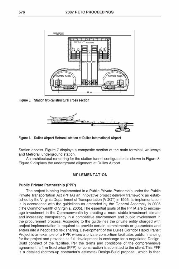
The mined portions of Dulles Airport Station will be constructed using NATM tech-niques with excavation to be carried out by road headers. Initial support will consist ofrock reinforcement and shotcrete lining. All mined station and associated structureswill be waterproofed using an open, “umbrella type” waterproofing system with sidewalldrain pipes. The station platform is about 25 meters below the ground surface. To allowfor a twin station tunnel configuration, where there are two parallel station vaults, thecenterline track-to-track distance is 28 meters. Both station platform tunnels are183 meters (600 feet) long and unobstructed by vertical circulation. The station plat-forms are connected with cross-passages between the station tunnels. Access to theplatforms is provided by a central access structure located between the two stationvaults. Figure 6 displays a typical station tunnel configuration at the central cross pas-sage with 5.2 meters wide platforms.
All station construction will be mined except for the mezzanine and ancillaryrooms, which will be constructed using cut-and-cover techniques. Mined stationconstruction has been selected to minimize disruption to airport activities. Surfacedisruptions will therefore generally be limited to Mezzanine and ancillary roomconstruction using shallow (±8 meters) cut-and-cover excavation while maintainingairport pedestrian circulation above, except for the time period when the mezzaninebox will be connected to an existing pedestrian tunnel “Node” that will provide Metrorail
Figure 5. Typical TBM tunnel section
RETC2007.bk Page 575 Thursday, April 19, 2007 1:48 PM
576 2007 RETC PROCEEDINGS
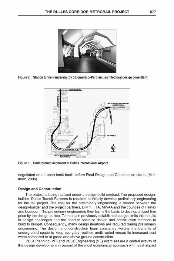
Station access. Figure 7 displays a composite section of the main terminal, walkwaysand Metrorail underground station.
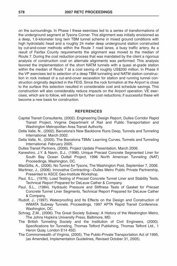
An architectural rendering for the station tunnel configuration is shown in Figure 8.Figure 9 displays the underground alignment at Dulles Airport.
IMPLEMENTATION
Public Private Partnership (PPP)
The project is being implemented in a Public-Private-Partnership under the PublicPrivate Transportation Act (PPTA) an innovative project delivery framework as estab-lished by the Virginia Department of Transportation (VDOT) in 1995. Its implementationis in accordance with the guidelines as amended by the General Assembly in 2005(The Commonwealth of Virginia, 2005). The essential goals of the PPTA are to encour-age investment in the Commonwealth by creating a more stable investment climateand increasing transparency in a competitive environment and public involvement inthe procurement process. According to the guidelines the private entity charged withproject implementation is required to provide certain commitments or guarantees andenters into a negotiated risk sharing. Development of the Dulles Corridor Rapid TransitProject is an example of a PPP, where a private consortium facilitates public financingfor the project and provides its full development in exchange for a negotiated Design-Build contract of the facilities. Per the terms and conditions of the comprehensiveagreement, a firm fixed price (FFP) for construction is submitted to the client. This FFPis a detailed (bottom-up contractor’s estimate) Design-Build proposal, which is then
Figure 6. Station typical structural cross section
Figure 7. Dulles Airport Metrorail station at Dulles International Airport
RETC2007.bk Page 576 Thursday, April 19, 2007 1:48 PM
THE DULLES CORRIDOR METRORAIL PROJECT 577
negotiated on an open book basis before Final Design and Construction starts. (Mar-tinez, 2006).
Design and Construction
The project is being realized under a design-build contract. The proposed design-builder, Dulles Transit Partners is required to initially develop preliminary engineeringfor the rail project. The cost for the preliminary engineering is shared between thedesign-builder and the project partners, DRPT, FTA, MWAA and the counties of Fairfaxand Loudoun. The preliminary engineering then forms the basis to develop a fixed firmprice by the design-builder. To maintain previously established budget limits this resultsin design challenges and the need to optimize design and construction methods tobuild to budget. Consequently, many design iterations are required during preliminaryengineering. The design and construction team constantly weighs the benefits ofunderground space to keep everyday routines undisrupted versus its increased costwhen compared to at grade and above ground construction.
Value Planning (VP) and Value Engineering (VE) exercises are a central activity ofthe design development in pursuit of the most economical approach with least impact
Figure 8. Station tunnel rendering (by diDomenico+Partners, architectural design consultant)
Figure 9. Underground alignment at Dulles International Airport
RETC2007.bk Page 577 Thursday, April 19, 2007 1:48 PM
578 2007 RETC PROCEEDINGS
on the surroundings. In Phase I these exercises led to a series of transformations ofthe underground segment at Tysons Corner. This alignment was initially envisioned asa deep, 1.6-kilometer long twin TBM tunnel scheme in mixed ground conditions withhigh hydrostatic head and a roughly 24 meter deep underground station constructedby cut-and-cover methods within the Route 7 road lanes, a busy traffic artery. As aresult of Fairfax County requirements the alignment was moved to the median ofRoute 7. During the cost reduction process that was mandated by the client a rigorousanalysis of construction cost on alternate alignments was performed. This analysisfavored the implementation of the short NATM tunnels with a quasi at-grade stationwithin the median of Route 7 at a cost saving of roughly US$200 million. In Phase IIthe VP exercises led to selection of a deep TBM tunneling and NATM station construc-tion in rock instead of a cut-and-cover excavation for station and running tunnel con-struction originally depicted in the FEIS. Since the rock formation at the Airport is closeto the surface this selection resulted in considerable cost and schedule savings. Thisconstruction will also considerably reduce impacts on the Airport operation. VE exer-cises, which are to follow, will search for further cost reductions; if successful these willbecome a new basis for construction.
REFERENCES
Capital Transit Consultants, (2002). Engineering Design Report, Dulles Corridor RapidTransit Project, Virginia Department of Rail and Public Transportation andWashington Metropolitan Area Transit Authority.
Della Valle, N., (2002). Barcelona’s New Backbone Runs Deep, Tunnels and TunnelingInternational. March 2002.
Della Valle, N., (2005). The Barcelona TBMs’ Learning Curves, Tunnels and TunnelingInternational. February 2005.
Dulles Transit Partners, (2006). Project Update Presentation, March 2006.Kaneshiro, J.Y. & Navin, S.J., (1996). Unique Precast Concrete Segmented Liner for
South Bay Ocean Outfall Project, 1996 North American Tunneling (NAT)Proceedings, Washington, DC.
MacGillis, A., (2006). No Tunnel for Tysons, The Washington Post, September 7, 2006.Martinez, J., (2006). Innovative Contracting—Dulles Metro Public Private Partnership,
Presented to ASCE Geo-Institute Workshop.Paul, S.L., (1978). Load Testing of Precast Concrete Tunnel Liner and Stability Tests,
Technical Report Prepared for DeLeuw Cather & Company.Paul, S.L., (1984). Hydraulic Pressure and Stiffness Tests of Gasket for Precast
Concrete Tunnel Liner Segments, Technical Report Prepared for DeLeuw Cather& Company.
Rudolf, J., (1997). Waterproofing and Its Effects on the Design and Construction ofWMATA Subway Tunnels. Proceedings, 1997 APTA Rapid Transit Conference.Washington, DC.
Schrag, Z.M., (2006). The Great Society Subway: A History of the Washington Metro,The Johns Hopkins University Press, Baltimore, MD.
The British Tunneling Society and the Institution of Civil Engineers, (2000).Specifications for Tunneling, Thomas Telford Publishing, Thomas Telford Ltd., 1Heron Quay, London E14 4SD.
The Commonwealth of Virginia, (2005). The Public-Private Transportation Act of 1995,(as Amended, Implementation Guidelines, Revised October 31, 2005).
RETC2007.bk Page 578 Thursday, April 19, 2007 1:48 PM