The device bears the CE label in accordance with the ... bc380 manual_en.pdfinformation regarding...
91
Transcript of The device bears the CE label in accordance with the ... bc380 manual_en.pdfinformation regarding...


2
The device bears the CE label in accordance with the provisions of Medical Device Directive
93/42/EEC.
THE PERSONS RESPONSIBLE FOR PLACING DEVICES ON THE EC MARKET UNDER MDD
93/42/EEC
SELVAS Healthcare, Inc.
155, Shinseong-ro, Yuseong-gu, Daejeon, 34109 Republic of Korea
TEL: 82-42-879-3000, FAX: 82-42-864-4462
VITAKO Sp. z o.o.
ul. Stanisława Żaryna 7c 02-593 Warszawa, POLAND
TEL: +48 505 522 888

3
CONTENTS
INTRODUCTION ··································································································· 5
1. INTENDED USE........................................................................................................................ 5
2. WORD DEFINITIONS................................................................................................................ 5
3. CLASSIFICATION AND COMPLIANCE.................................................................................... 6
4. SAFETY PRECAUTIONS.......................................................................................................... 6
5. SAFETY SYMBOLS AND INFORMATION............................................................................... 11
6. Guidance for Electromagnetic compatibility(EMC) ................................................................... 14
ABOUT BODY COMPOSITION ··················································································· 19
TERM AND FUNCTION OF EACH PART ······································································ 21
1. Basic Package ··································································································· 21
2. Options ············································································································ 22
3. Appearance of the device ····················································································· 24
INSTALLATION ········································································································ 27
1. Power Supply ···································································································· 27
2. Peripheral Device Installation ················································································ 28
1) Connecting Computer ······················································································ 28
2) Connecting Printer ··························································································· 29
3) Connecting Blood Pressure Monitor ······································································ 31
4) Replacing of thermal paper (OPTION) ·································································· 32
SYSTEM SETUP ····································································································· 34
1. Entering SYSTEM SETUP ··················································································· 34
2. Menu in SYSTEM SETUP ···················································································· 35
3. Setup ·············································································································· 36
MEASUREMENT AND ANALYSIS ··············································································· 41
1. Precautions for Measurement ··············································································· 41
2. Correct Posture ································································································· 42
3. Measurement ···································································································· 44
RESULT INTERPRETATION ······················································································· 50
STORAGE & MAINTENANCE ····················································································· 55
4
ERROR & REPAIR ································································································· 56
1. Troubleshooting & Repair ··················································································· 56
2. Error Occurrence & Repair ················································································· 57
AFTER SERVICE ··································································································· 58
1. AFTTER SERVICE ·························································································· 58
2. PACKING AND TRANSPORT ············································································ 58
SPECIFICATION ···································································································· 59
WARRANTY ········································································································· 61
INSTRUCTIONS FOR ASSEMBLY ············································································· 62
1. HOW TO INSTALL The DEVICE ········································································· 62
2. ASSEMBLING The HEIGHT METER (OPTIONAL) ················································· 69
3. ASSEMBLING The ANKLE ELECTRODE (OPTIONAL) ··········································· 80
4. ASSEMBLING The THERMAL PRINTER (OPTIONAL) ············································ 86

5
INTRODUCTION
We thank you for choosing the BC380.
Please familiarize yourself with these instructions before using this product and always keep them
on hand for easy reference. If you are not sure about an operation, or you experience problems
while using the product, please contact our service center.
We will provide you with detailed instructions.
1. INTENDED USE
This device measures impedance by bioelectrical impedance analysis method and provides lots of
information using measured impedance and inputted personal data (height, age, gender, weight).
It shows body composition of MBF, LBM, SLM, SMM, TBW, protein mass, mineral mass, etc. and
information regarding BMI, PBF, BMR, abdominal analysis, Target to control, segmental analysis,
Body composition change, etc.
2. WORD DEFINITIONS
To ensure safe operation and long term performance stability, it is essential that you fully
understand the functions, operating and maintenance instructions by reading this manual before
operating your unit.
Particular attention must be paid to all warnings, cautions and notes incorporated herein.
The following conventions are used throughout the manual to denote information of special
emphasis.
Warning “Warning” indicates important information about the presence of a hazard
which may cause severe personal injury, loss of substantial property, damage if
the warning is ignored.
Caution “Caution” indicates important information about the presence of a hazard which
may cause minor personal injury or property damage if the caution is ignored.
Note “Notice” indicates important information in order to notify installation, operation
or maintenance of this device. “Notice” is important but not hazard-related.
Hazard warnings are not included here.

6
3. CLASSIFICATION AND COMPLIANCE
1) This device is classified as;
- Class 1 type-BF against electric shock
- Ordinary equipment without protection against ingress of water
- Equipment not suitable for use in presence of a flammable anesthetic mixture by standard of
EN 60601-1:2006/A1:2013(Basic safety and essential performance of Medical Electrical
Equipment)
2) This device is complied with Class A for Noise-Emission, Level B for Noise-immunity, by
standard of EN 60601-1-2:2007/AC:2010(Electromagnetic Compatibility Requirements).
4. SAFETY PRECAUTIONS
This device is designed and manufactured with consideration of the safety of the operator and
subject and also the reliability of the unit.
The following warnings, precautions and notes must be observed for safety;
Warning During measurement of the body composition, a microcurrent of 180μA flows through
the body. Individuals who have any kind of implanted active medical devices, such as
pacemakers, should not use this equipment because the microcurrent can cause
malfunction in the implanted device.
Warning To prevent fire hazard, use only a correctly wired (100-240VAC) outlet, and do not use
a MSO(Multiple Socket Outlet) with other device that is not in compliance with EN
60601-1.
Warning To reduce the risk of electric shock or product damage, never plug-in or plug-out with
wet hands.
Warning Physically disabled persons should not attempt to take measurements alone, but
instead should have their caretakers assist them in using the device.
Caution The unit must be operated only by, or under supervision of a qualified person with our
company or our distributors.
7
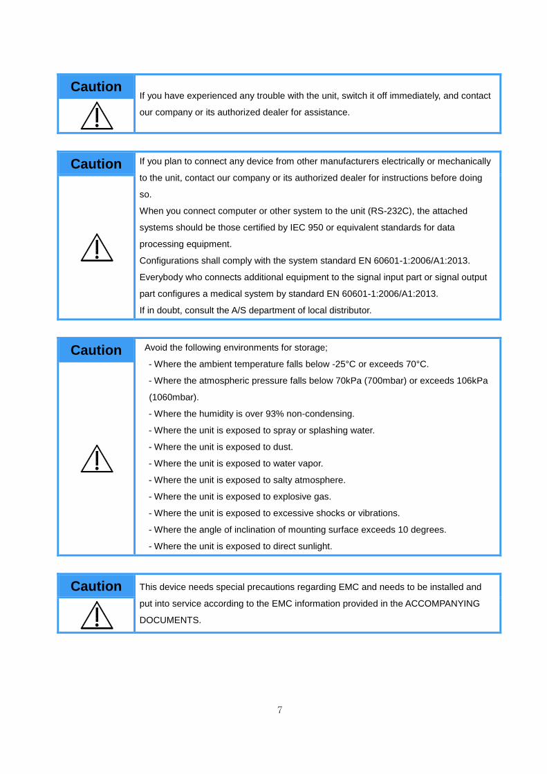
Caution If you have experienced any trouble with the unit, switch it off immediately, and contact
our company or its authorized dealer for assistance.
Caution If you plan to connect any device from other manufacturers electrically or mechanically
to the unit, contact our company or its authorized dealer for instructions before doing
so.
When you connect computer or other system to the unit (RS-232C), the attached
systems should be those certified by IEC 950 or equivalent standards for data
processing equipment.
Configurations shall comply with the system standard EN 60601-1:2006/A1:2013.
Everybody who connects additional equipment to the signal input part or signal output
part configures a medical system by standard EN 60601-1:2006/A1:2013.
If in doubt, consult the A/S department of local distributor.
Caution Avoid the following environments for storage;
- Where the ambient temperature falls below -25°C or exceeds 70°C.
- Where the atmospheric pressure falls below 70kPa (700mbar) or exceeds 106kPa
(1060mbar).
- Where the humidity is over 93% non-condensing.
- Where the unit is exposed to spray or splashing water.
- Where the unit is exposed to dust.
- Where the unit is exposed to water vapor.
- Where the unit is exposed to salty atmosphere.
- Where the unit is exposed to explosive gas.
- Where the unit is exposed to excessive shocks or vibrations.
- Where the angle of inclination of mounting surface exceeds 10 degrees.
- Where the unit is exposed to direct sunlight.
Caution This device needs special precautions regarding EMC and needs to be installed and
put into service according to the EMC information provided in the ACCOMPANYING
DOCUMENTS.

8
Caution Cross contamination is possible because this equipment is used with bare hands and
feet. Refer to the cleaning and disinfecting methods in this manual.
Caution Measurements may be impaired if this device is used near televisions, microwave
ovens, X-ray equipment or other devices with strong electrical fields. To prevent such
interference, use the meter at a sufficient distance from such devices or turn them off.
Prohibition Do not disassemble or alter the device under any circumstances, as this could result
in electric shock or injury as well as adversely affect the precision of measurements.
This device is specified as Class 1 type BF unit under the standard EN 60601-1:
2006/A1:2013(Basic safety and essential performance of Medical Electrical
Equipment). Therefore, patients must not touch or handle inner side of the system at
any time.
Prohibition Do not to touch signal input, signal output or other connectors, and the patient
simultaneously.
Prohibition The unit has previously been adjusted in the factory for optimum performance.
Do not attempt to adjust switches or any other things except those specified in this
manual for operation.
Prohibition Never pour any liquid directly on the scale platform, as it may leak and cause internal
damage.
Prohibition Never jump on the Weighing Platform, there may be a risk of stumbling and
malfunction of the equipment.

9
Note This equipment has been tested and found to comply with the limits for medical devices
according to EN 60601-1-2:2015. These limits are designed to provide reasonable
protection against harmful interference in a typical medical installation. This
equipment generates uses and can radiate radio frequency energy and, if not installed
and used in accordance with the instructions, may cause harmful interference to other
devices in the vicinity. However, there is no guarantee that interference will not occur
in a particular installation. If this equipment does cause harmful interference to other
devices, which can be determined by turning the equipment off and on, the user is
encouraged to try to correct the interference by one or more of the following measures:
- Reorient or relocate the receiving device.
- Increase the separation between the equipment.
- Connect the equipment into an outlet on a circuit different from that to which the
other device(s) are connected.
- Consult the manufacturer or field service technician for help.
Note Place the Weighing Platform on a level and stable surface. If the equipment is used
when the Weighing Platform is unstable because not all feet are on the surface, there
may be a risk of stumbling or inaccurate measurement.
Note Note that portable and mobile RF communications equipment can affect MEDICAL
ELECTRICAL EQUIPMENT.
Note Consult a physician or a trained health professional for interpretation of measurement
results.
Note In case of patients who have certain diseases, the estimates might be different.

10
Note Incorrect operation or failure of user to maintain the unit spares the manufacturer or his
agent of the responsibility for system’s non-compliance with specifications or
responsibility for any damage or injury.
This manual is made for informational purposes and this manual and product are not
meant to be a substitute for the advice provided by your own physician or other medical
expert. You should not use the information contained in the product for diagnosis or
treatment of health problems or prescription of medication by yourself. If you have or
suspect that you have a medical problem, consult with your physician promptly.
Defective units or accessories must be packed in the replacement cartons to be
shipped off from you to our company.
Shipping and insurance costs for return of defective unit must be prepaid by the users.
Warning Do not modify this equipment without authorization of the manufacturer.
Warning Connect the earth placed on the backside of this device to terminal plate to prevent any
electric shock from leakage current or a potential difference.
Warning To avoid the risk of electric shock, this equipment must only be connected to supply
mains with protective earth.
Caution Do not put anything other than the main unit and Selvas’s blood pressure monitor
within 1.5 m from the patient.
Caution Do not touch any other devices other than those specified by the manufacturer.

11
5. SAFETY SYMBOLS AND INFORMATION
The International Electro-technical Commission (IEC) has established a set of symbols for
medical electrical equipment which classify a connection or warning of any potential hazard.
The classifications and symbols are shown below. Save these instructions for your safety.
Degree of protection against electric shock: TYPE BF
Please observe operating instructions
General warning sign
General prohibition sign
General mandatory action sign
Caution
Waste Electrical and Electronic Equipment (WEEE)
The device could be sent back to the manufacturer for recycling or
proper disposal after their useful lives. Alternatively the device shall be
disposed in accordance with national laws after their useful lives.
/
“ON / OFF” key : Turn the power ON / OFF
Class II equipment

12
This symbol is used inside system.
Identifies the point where the safety ground of the system is fastened to
the chassis.
Do not open. This is for factory only.
Alternating current
Direct current
Date of manufacture
Manufacturer
Non-ionizing radiation
CE mark
Serial No.
Authorized representative in the European community.
Keep dry
This way up
Fragile

13
Use no hooks
For indoor use only
RoHS2
14
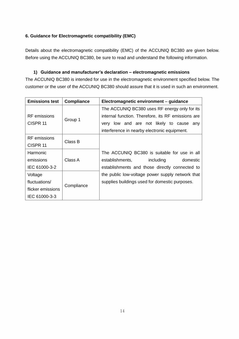
6. Guidance for Electromagnetic compatibility (EMC)
Details about the electromagnetic compatibility (EMC) of the ACCUNIQ BC380 are given below.
Before using the ACCUNIQ BC380, be sure to read and understand the following information.
1) Guidance and manufacturer’s declaration – electromagnetic emissions
The ACCUNIQ BC380 is intended for use in the electromagnetic environment specified below. The
customer or the user of the ACCUNIQ BC380 should assure that it is used in such an environment.
Emissions test Compliance Electromagnetic environment – guidance
RF emissions
CISPR 11 Group 1
The ACCUNIQ BC380 uses RF energy only for its
internal function. Therefore, its RF emissions are
very low and are not likely to cause any
interference in nearby electronic equipment.
RF emissions
CISPR 11 Class B
The ACCUNIQ BC380 is suitable for use in all
establishments, including domestic
establishments and those directly connected to
the public low-voltage power supply network that
supplies buildings used for domestic purposes.
Harmonic
emissions
IEC 61000-3-2
Class A
Voltage
fluctuations/
flicker emissions
IEC 61000-3-3
Compliance

15
2) Guidance and manufacturer’s declaration – electromagnetic immunity
The ACCUNIQ BC380 is intended for use in the electromagnetic environment specified below. The
customer or the user of the ACCUNIQ BC380 should assure that it is used in such an environment.
Immunity test IEC 60601 test
level
Compliance
level
Electromagnetic environment-
guidance
Electrostatic
discharge(ESD)
IEC 61000-4-2
±6kV: Contact
±8kV: Air
±6kV: Contact
±8kV: Air
Floors should be wood, concrete
or ceramic tile. If floors are
covered with synthetic material,
the relative humidity should be at
least 30 %.
Electrical fast
transition/burst
IEC 61000-4-4
±2kV: Power
supply lines
±1kV:
Input/output
lines
±2kV: Power
supply lines
±1kV:
Input/output
lines
Mains power quality should be
that of a typical commercial or
hospital environment.
Surge
IEC 61000-4-5
±1 kV
differential
mode
±2 kV common
mode
±1 kV
differential
mode
±2 kV common
mode
Mains power quality should be
that of a typical commercial or
hospital environment.
Voltage drops,
dips, and
fluctuations of
input power
supply line IEC
61000-4-11
<5 % UT
(>95 % dip in
UT)
for 0,5 cycle
40 % UT
(60 % dip in UT)
for 5 cycles
70 % UT
(30 % dip in UT)
for 25 cycles
<5 % UT
(>95 % dip in
UT)
for 5 sec
<5 % UT
(>95 % dip in
UT)
for 0,5 cycle
40 % UT
(60 % dip in
UT)
for 5 cycles
70 % UT
(30 % dip in
UT)
for 25 cycles
<5 % UT
(>95 % dip in
UT)
for 5 sec
Mains power quality should be
that of a typical commercial or
hospital environment. If the user
of the ACCUNIQ BC380 requires
continued operation during power
mains interruptions, it is
recommended that the ACCUNIQ
BC380 be powered from an
uninterruptible power supply or a
battery.

16
Magnetic field
of commercial
frequency
(50/60Hz)
IEC 61000-4-8
3 A/m 3 A/m
Power frequency magnetic fields
should be at levels characteristic
of a typical location in a typical
commercial or hospital
environment.
Note UT is the a.c. mains voltage prior to application of the test level.
3) Guidance and manufacturer’s declaration – electromagnetic immunity 2
The ACCUNIQ BC380 is intended for use in the electromagnetic environment specified below. The
customer or the user of the ACCUNIQ BC380 should assure that it is used in such an environment.
Immunity test IEC 60601 test
level
Compliance
level
Electromagnetic environment-
guidance
Conducted RF
IEC 61000-4-6
Radiated RF
IEC 61000-4-3
3 Vrms
150 kHz to 80 MHz
3 V/m
80 MHz to 2,5 GHz
3 Vrms
3 V/m
Portable and mobile RF
communications equipment should
be used no closer to any part of the
ACCUNIQ BC380, including
cables, than the recommended
separation distance calculated from
the equation applicable to the
frequency of the transmitter.
Recommended separation
distance
d =1.2
d =1.2 80 MHz to 900 MHz
d =2.3 900 MHz to 2,5 GHz
where P is the maximum output
power rating of the transmitter in
watts (W) according to the
transmitter manufacturer and d is
17
the recommended separation
distance in meters (m).
Field strengths from fixed RF
transmitters, as determined by an
electromagnetic site survey,a
should be less than the compliance
level in each frequency range.b
Interference may occur in the
vicinity of equipment marked with
the following symbol:
Note 1. At 80 MHz and 900 MHz, the higher frequency range applies.
2 These guidelines may not apply in all situations. Electromagnetic propagation
is affected by absorption and reflection from structures, objects and people.
a Field strengths from fixed transmitters, such as base stations for radio
(cellular/cordless) telephones and land mobile radios, amateur radio, AM and
FM radio broadcast and TV broadcast cannot be predicted theoretically with
accuracy. To assess the electromagnetic environment due to fixed RF
transmitters, an electromagnetic site survey should be considered. If the
measured field strength in the location in which the ACCUNIQ BC380 is used
exceeds the applicable RF compliance level above, the ACCUNIQ BC380
should be observed to verify normal operation. If abnormal performance is
observed, additional measures may be necessary, such as reorienting or
relocating the ACCUNIQ BC380.
b Over the frequency range 150 kHz to 80 MHz, field strengths should be less
than 3 V/m.

18
4) Recommended separation distances between portable and mobile RF communications
equipment and the ACCUNIQ BC380
The ACCUNIQ BC380 is intended for use in an electromagnetic environment in which radiated RF
disturbances are controlled. The customer or the user of the ACCUNIQ BC380 can help prevent
electromagnetic interference by maintaining a minimum distance between portable and mobile RF
communications equipment (transmitters) and the ACCUNIQ BC380 as recommended below,
according to the maximum output power of the communications equipment.
Rated maximum
output power
of transmitter
W
Separation distance according to frequency of transmitter
m
150 kHz to 80 MHz
d =1.2
80 MHz to 900 MHz
d =1.2
900 MHz to 2,5 GHz
d =1.2
0.01 0.12 0.12 0.23
0.1 0.38 0.38 0.73
1 1.2 1.2 2.3
10 3.8 3.8 7.3
100 12 12 23
For transmitters rated at a maximum output power not listed above, the recommended
separation distance d in meters (m) can be estimated using the equation applicable to
the frequency of the transmitter, where P is the maximum output power rating of the
transmitter in watts (W) according to the transmitter manufacturer.
Note 1. At 80 MHz and 900 MHz, the separation distance for the higher frequency
range applies.
2. These guidelines may not apply in all situations. Electromagnetic propagation
is affected by absorption and reflection from structures, objects and people.

19
ABOUT BODY COMPOSITION
1. Body Composition
Human body consists of body fat mass and lean body mass. Lean body mass refers to non-fat
components of human body like body water, muscles, minerals, etc.
Body water consists of both intra- and extra-cellular water, and the ratio between them is
controlled and maintained within a certain range. Body fat is stored beneath the skin and
between abdominal organs. Body fat is hydrolyzed to make energy needed to perform normal
physiological functions when energy supply through food intake is not sufficient, but excessive fat
in the body is a type of disorder, often caused by adverse lifestyle conditions.
Healthy people maintain a steady proportional balance of body composition, but unhealthy
people fail to keep this balance. When the balance in body composition is compromised,
diseases like obesity, malnutrition, osteoporosis, etc. can result.
2. Obesity
Various methods can be used to assess obesity, but the key factor in obesity assessment is the
amount of fat accumulated in the body.
In general, obesity is defined as the state of, not only excessive weight compared with height
(visible obesity), but also excessive body fat compared with weight (invisible or visible obesity).
Strictly speaking obesity is the state in which body fat occupies a considerably high proportion as
compared to weight.
3. Necessity of Body Composition Analysis
Body Composition Analysis is a useful indicator for identifying possible health problems. Body
composition analysis enables professionals to detect obesity or imbalance in body composition at
an early stage and helps subjects keep their body healthy.
4. Waist to hip ratio
Waist to hip ratio (W.H.R.) shows the distribution of fat stored in one’s abdomen and hip. It is
simple but useful to assess body fat distribution. Body fat is stored in two distinct ways. They are
often categorized as 'apple' and 'pear' types. Apple type indicates a larger waist than hip and
pear type is characterized by a larger hip than waist. If body fat in the abdomen increases, the
risk of cardiovascular diseases, diabetes, etc. becomes higher.

20
5. Abdominal Fatness
Body fat consists of subcutaneous fat and visceral fat. Visceral obesity is considered to be a
critical risk factor along with Percentage of body fat.
Lipoprotein lipase can be easily activated in visceral fat, and it causes visceral fat to be dissolved
easily. Dissolved visceral fat goes into liver through the blood vessel and causes a fatty liver or
increases lipid in the blood. It also elevates the risk of hyperinsulinemia, hypertension, and
cardiovascular disease.
Visceral fat generally occupies 10 ~ 20 % of body fat. Visceral obesity is assessed based on the
indicators below.
- the cross sectional fat area between L4 ~ L5 is 100 cm2 and over
- the visceral fat to subcutaneous fat ratio is 0.4 and over
- the waist to hip ratio (W.H.R.) is over 0.9 (male) / 0.85 (female)
- the circumference of waist is over 102 cm/40 inches (male) _ 88 cm / 35 inches (female)
Visceral fat increases after 30s in men and after Menopause in women. It is more common in
men than women and the old than the young. Visceral fat tends to increase with aging. Because
the combustion rate per minute of visceral fat is higher than that of subcutaneous fat, visceral fat
can be easily reduced by exercise or dietary control in case of abdominal obesity. W.H.R. is the
ratio of waist to hip circumference and has relation to one’s figure.
6. Segmental Analysis
This device analyzes soft lean mass and mass of body fat in five body segments: trunk, right arm,
left arm, right leg, and left leg. This function can be used as an assessment tool to evaluate the
result of exercise or rehabilitation treatment.
7. Age Matched of Body
It is the estimated physical age of the subject considering the body composition analysis result,
gender, and biological age. This is calculated by comparing the optimal body composition based
on the gender and biological age of the subject with the actual analyzed body composition. It can
be used to evaluate the subject’s health and body development.

21
TERM AND FUNCTION OF EACH PART
1. Basic Package
The package of the ACCUNIQ BC380includes the following components:
Name Specification Quantity
Main body 1EA
Accessories
User manual CD or Paper 1EA
Adapter DC 12V, 5A 1EA
USB Cable 3m 1EA
Data management program ACCUNIQ Manager (CD) 1EA
Bolts 6X20mm 2EA
L-wrench 4mm 1EA
Body Cover 1EA
※ Model or specification of accessories can be changed according to market supply and demand.
Body Pass Plus
② User manual ① Main body
④ USB Cable
③ Adapter
⑥ Bolts
⑦ 4mm L-wrench
⑤ Data management
program
⑧ Body Cover
22
USB memory
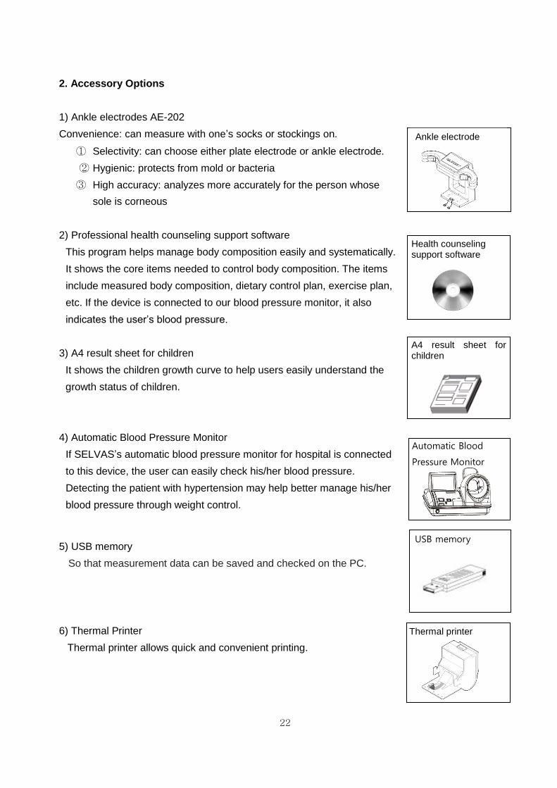
2. Accessory Options
1) Ankle electrodes AE-202
Convenience: can measure with one’s socks or stockings on.
① Selectivity: can choose either plate electrode or ankle electrode.
② Hygienic: protects from mold or bacteria
③ High accuracy: analyzes more accurately for the person whose
sole is corneous
2) Professional health counseling support software
This program helps manage body composition easily and systematically.
It shows the core items needed to control body composition. The items
include measured body composition, dietary control plan, exercise plan,
etc. If the device is connected to our blood pressure monitor, it also
indicates the user’s blood pressure.
3) A4 result sheet for children
It shows the children growth curve to help users easily understand the
growth status of children.
4) Automatic Blood Pressure Monitor
If SELVAS’s automatic blood pressure monitor for hospital is connected
to this device, the user can easily check his/her blood pressure.
Detecting the patient with hypertension may help better manage his/her
blood pressure through weight control.
5) USB memory
So that measurement data can be saved and checked on the PC.
6) Thermal Printer
Thermal printer allows quick and convenient printing.
Health counseling support software
A4 result sheet for children
Automatic Blood
Pressure Monitor
Thermal printer
Ankle electrode
23
Height meter
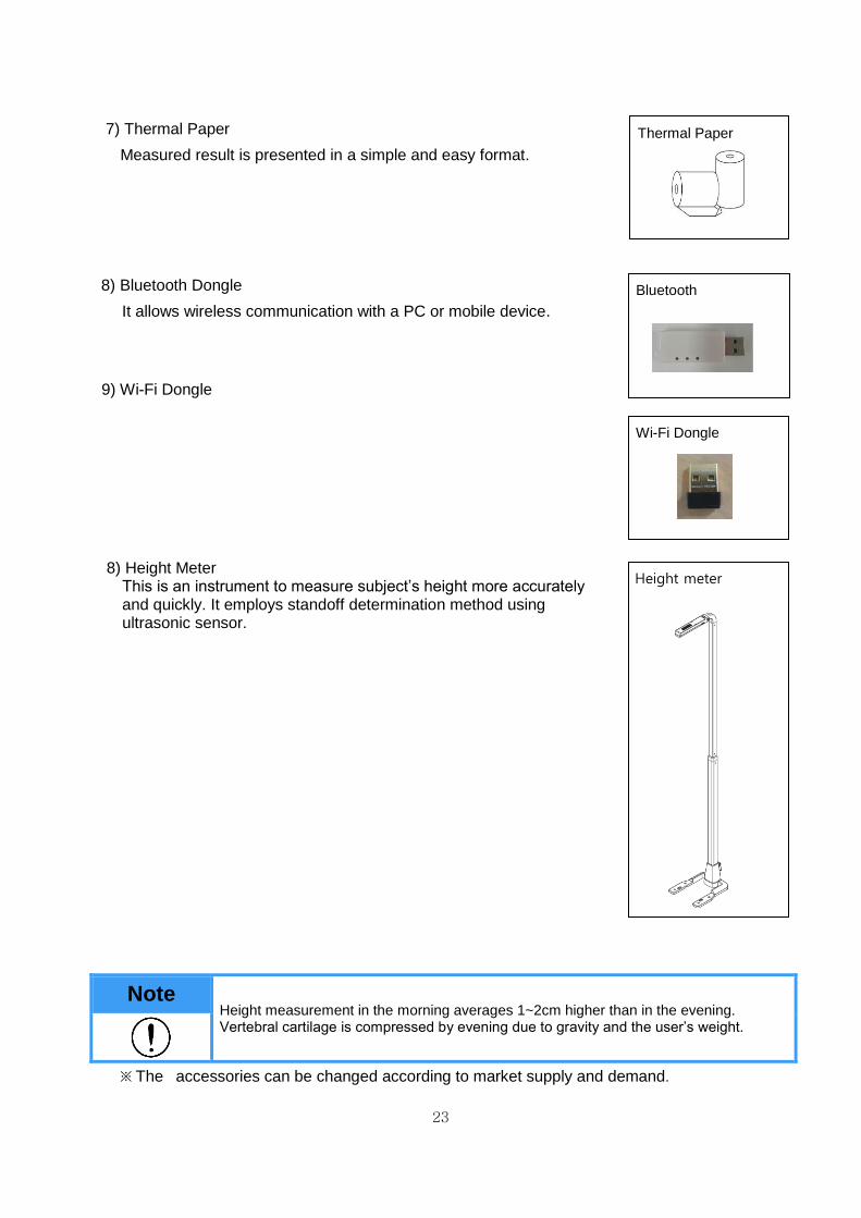
7) Thermal Paper
Measured result is presented in a simple and easy format.
8) Bluetooth Dongle
It allows wireless communication with a PC or mobile device.
9) Wi-Fi Dongle
8) Height Meter This is an instrument to measure subject’s height more accurately and quickly. It employs standoff determination method using ultrasonic sensor.
Note Height measurement in the morning averages 1~2cm higher than in the evening. Vertebral cartilage is compressed by evening due to gravity and the user’s weight.
※ The accessories can be changed according to market supply and demand.
Thermal Paper
Bluetooth
Wi-Fi Dongle

24
3. Appearance of the device
④ Front Face
Color LCD panel as touch screen.
It displays the procedure and results.
Handle Electrode
Handle Electrode measure the impedance by sending harmless electric current to the body.
Hold them with the hands during measurement.
Handle Electrode
(Applied Part)
Color LCD

25
2) Rear Panel
Power switch (POWER): Use to turn on/off the power.
Adapter port (ADAPTER): Connect power adapter.
PC port: Connect to a computer.
Height port: Connect the external height meter. (OPTIONAL)
Wi-Fi port: Connect the Wi-Fi Dongle. (OPTIONAL)
USB port: Connect a USB drive. (OPTIONAL)
Bluetooth port: Connect via Bluetooth. (OPTIONAL)
Printer port: Connect SELVAS Thermal Printer. (OPTIONAL)
Blood pressure port: Connect SELVAS Healthcare blood pressure monitor (OPTIONAL)

26
3) Unit Base
Weight scale: Consists of four plate electrodes and measures weight.
Plate electrode: Measures the impedance. The user should step on it with bare feet.
Weight scale (Applied Part)
Plate electrode (Applied Part)

27
INSTALLATION
1. Power Supply
Connect the power cable to the 'ADAPTER INPUT' located on the lower back panel of the device.
Connect the cable. Turn on the power switch located next to the Power input, and after a
moment initial screen animation is displayed.
Caution 1. Before connecting a peripheral device to the unit, the power should be turned off.
Otherwise both devices may be damaged by electric shock or malfunction.
2. When the unit and the peripheral devices are connected, the BC380 should be
powered on first to preserve proper function and ensure safe operation of all devices.
3. This device should be powered only using the cable provided by SELVAS Healthcare.
4. Be careful not to touch the base part of the scale when switching on the device, as
any weight on the plate electrode during power on can cause measurement errors
with the scale’s zero point.
5. Do not install the equipment where power can not be disconnected.

28
2. Peripheral Device Installation
1) Connecting to a Computer
Connect the “PC” port located on the rear panel of this device to the USB port on your
computer using the USB cable. Or you can connect through Bluetooth (optional).
Note 1. If using the USB port, the cable should be connected to the computer port on the
BC380.
2. Before using the computer port, the USB driver should be installed.
For more information, please refer to the manual and software CD.
Note 1. In order to save, search and retrieve the users’ data, the user should connect the BCA
to a computer with our free data management software installed. Printing is done via
the computer in this case.
2. The professional consulting software provides various options for printouts. When
using the software, the pre-printed result sheet is not used.
3. Refer to the user’s manual for installation of the software supplied on the CD.
Caution The PC that connects to the device must comply with IEC60950-1.

29
2) Connecting a Printer
① Connecting the device and the printer directly
Connect the A4 printer offered with this device to the “PRINTER” port located on the rear
panel of this device via a USB cable.

30
② Connecting the device, computer, and the printer
Connect a computer to the “PC” port located on the rear panel of the device using a USB
cable. Connect the printer to the computer with a printer cable. The result sheet can be
printed out from the PC program.

31
3) Connecting the Blood Pressure Monitor
This device can be connected to the automatic blood pressure monitor from SELVAS
Healthcare. (Optional) Connect the blood pressure monitor to the “BLOOD PRESSURE” port
located on the rear panel of the device using the blood pressure monitor cable.

32
4) Replacing of thermal (Optional)
You should replace the thermal paper while the power is on.
① Turn the screws counterclockwise and open the cover as shown in the picture.
② Insert the thermal paper in the direction as shown in the picture.
③Insert the edge of the thermal paper into the printer slot just slightly. Thermal paper will be
printed and automatically cut.
④ Close the cover and secure the printer cover by turning the screws clockwise.
② ①
③ ④
④

33
4-1) FEED/CUT functions of thermal printer
• FEED Function
On the initial screen, press the " " icon at the left bottom and
enter the password ‘5555’ on the key pad.
Thermal paper will be printed.
• CUT Function
On the initial screen, press the " " icon at the left bottom and
enter the password ‘8888’ on the key pad.
Paper will be cut.
Note Do not pull on the thermal paper while printing. Paper will be cut automatically
when printing is complete.

34
SYSTEM SETUP
‘SYSTEM SETUP’ allows the users to change the setting of operational parameters.
1. Entering SYSTEM SETUP
On the initial screen, press the “ ” icon at the left bottom and enter the password ‘0-0-0-0’. The entering password can be changed in “Basic setting – Password”.
Note For the purpose of improvement, the contents in SYSTEM SETUP can be
changed.

35
2. Menu in SYSTEM SETUP
Menu items are displayed. The function of each icon is as follows.
Menu Setting Item
1 Basic Setting
Date / Time
Date Type
Unit change
Language
Volume
Password
2 Data Management
Data Check/Print/Delete
Copy data to Excel file
Data Backup/Restore
3 Printer
Printer connection
Select printer type
Automatic print settings and Number of auto prints
Print Position
4 Result Sheet
Result sheet setting
Logo
Adult / Child result sheet setting
Abdominal analysis result setting
5 Communication Internet
Bluetooth
6 Weight/Height
Weight Measurement or Input
Weight Calibration
Height Calibration
7 Option Management
Measurement electrode (foot electrode / ankle
electrode)
Optional equipment (Height meter / blood pressure
monitor)
8 Display Touch Calibration
9 A/S center
Contact Us
Trouble shooting
Remote check
Information

36
3. Setup
(1) Basic settings
- Date/Time: Use the ∧, ∨ buttons to set the current date and time.
- Date Type: Use the <, > buttons to select the desired date format: YYYY-MM-DD, MM-DD-YYYY
or DD-MM-YYYY.
- Unit change: Select the units for weight and height in kg / cm or lb / ft.
- Language: Set the language of menus and prompts.
- Volume: Set the volume of the announcement voice. (from 1 to 10)
- Password: Set password to be entered when entering user settings. The factory default password
is set to '0000'. Please note that if you forget your password after changing it, there is no way to
recover it.
Note If you press the 'Save Settings' button in the middle of setting your options, the options
you have set thus far will be entered. If you press the ' ' button, you will exit to the
previous screen. To cancel changing the settings, press the ' ' button. The original
settings are retained.

37
(2) Data Management
- Data Check/Print/Delete: You can view, print or delete data stored on the device.
- Copy data to Excel file: Export all or part of saved data to an Excel file.
- Data Backup/Restore: export data to a USB drive, or load data from a USB drive into the device.
(3) Printer
- Printer connection: Connect a printer.
- Select printer type: Select the type of printer to connect to.
- Automatic print settings and Number of auto prints: Select whether the printing is automatic or
manual and the number of prints.
- Print Position: Adjusts the printing position.
38
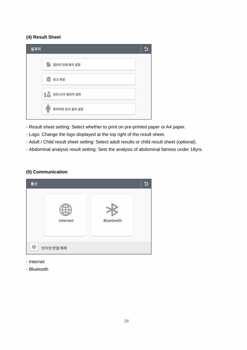
(4) Result Sheet
- Result sheet setting: Select whether to print on pre-printed paper or A4 paper.
- Logo: Change the logo displayed at the top right of the result sheet.
- Adult / Child result sheet setting: Select adult results or child result sheet (optional).
- Abdominal analysis result setting: Sets the analysis of abdominal fatness under 18yrs.
(5) Communication
- Internet
- Bluetooth

39
(6) Weight/Height
- Weight Measurement or Input: You can measure or input your weight.
- Weight Calibration: Calibrate the weight value.
- Height Calibration: Calibrate the height value.
(7) Option Management
- Measurement electrode (foot electrode / ankle electrode): You can select which electrode to use.
- Optional equipment (Height meter / blood pressure monitor): You can select whether to use these
optional devices.
40
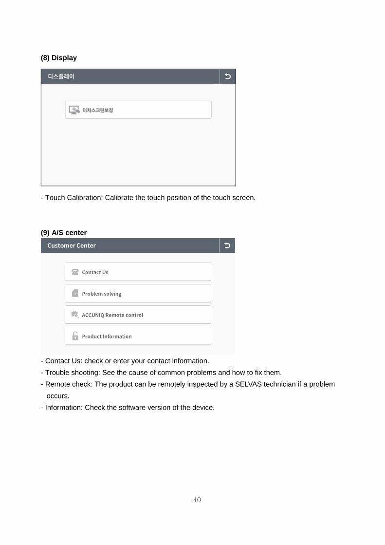
(8) Display
- Touch Calibration: Calibrate the touch position of the touch screen.
(9) A/S center
- Contact Us: check or enter your contact information.
- Trouble shooting: See the cause of common problems and how to fix them.
- Remote check: The product can be remotely inspected by a SELVAS technician if a problem
occurs.
- Information: Check the software version of the device.

41
1. Precaution for measurement
The reliability of the results is only as good as their accuracy. The "Accuracy" of the device is
determined by comparing the actual body composition and the results from the Body
Composition Analyzer. The "Reproducibility" is determined when the device gives the identical
results under the same conditions. In order to ensure the accuracy of the results, the following
guidelines should be observed.
① Water volume increases after a meal. Therefore, measure on an empty stomach.
- Measure 3 ~ 4 hours after a meal.
- Avoid beverages containing caffeine or beverages functioning as diuretics 4 hours before
measurement.
- Drink 2 cups of water 2 hours before the measurement.
② Before measurement, the subject should be in a stable condition.
- Measure 3 ~ 4 hours after a bath, a sauna, exercise or activity that causes a lot of sweating.
- Or measure before these activities.
③ Avoid drinking alcohol 24 hours before the measurement
④ Wear clothes as light as possible.
⑤ Once the subject is on the scale, avoid sudden movements from sitting to standing position
etc. Body fluid moves to the lower extremities and affects the results. Thus subjects should
be measured after maintaining a standing position for 5 minutes.
⑥ Clean both the electrodes and the skin contact points.
⑦ Changes in room temperature may affect the results. Measurement should be done in a
temperature around 20 °C.
⑧ Body composition and weight varies even throughout a day. Therefore, the measurement
should be performed at the same time every day. For a person who stands for a long period
of time during the day, it is advised to measure in the morning.
⑨ Go to the bathroom before measurement.
⑩ Maintain correct position and posture during the measurement.
In order to keep one's good health and a balanced body composition, check body composition
changes through continuous analysis and compare the results. Make sure that the body
composition is measured under the same physical and environmental conditions. If the condition
before the measurement, such as volume of a meal, meal time, and activities (exercise, sauna,
drinking lots of liquid, urination, etc.) are kept the same, the reproducibility of the device
measurement can be obtained. Therefore, the data can be used to accurately evaluate changes in
body composition.
MEASUREMENT AND ANALYSIS

42
2. Correct measurement position
1) How to touch electrodes
- Make sure that the plate electrodes are clean.
- Remove socks or stockings, and then stand on the plate electrodes.
- Be sure to remove sweat or foreign matter on the soles of your feet.
- Place your bare feet securely on the plate electrodes. Make sure no clothing is between the
soles of your feet and the plate electrodes.
When the ankle electrode is selected to measure body composition, pull down the socks as
shown in the picture, and make sure the user’s ankle is touching the electrode.
Caution When using the ankle electrode, be careful not to trip on the electrode before or after a measurement. Use the ankle electrode after reading and understanding the instructions carefully. Especially the elderly and the infirm should be careful of their safety while using the ankle electrode.
(O) Correct stand (X) Ankles are barely touched
(O) Correct stand (X) Imbalanced touch (X) Foreign matters

43
2) How to Touch Handle Electrodes
- Grip the handle electrodes using your fingers and palms.
- The 4 electrodes should be touched equally.
- Stretch both arms and spread them 30° from the body.
3) Measurement Posture
- Step on the scale with bare feet. Stretch both arms and spread them 30° from the body.
- Press and hold the start buttons with your thumbs for 2 ~ 3 seconds to start the measurement.
Once measuring starts, release the start buttons and hold the same position until the
measurement is complete.
- Do not speak or move your body until the measurement is complete.
- Do not bend or shake your arms until the measurement is complete.
- The measurement will be stopped if contact with all eight electrodes is not securely maintained.
(O) Correct grip (X) Imbalanced touch (X) Grip with only palm
Note If 8 electrodes are not perfectly touched during the measurement, the result is not
reliable or the device quits the measurement.
Note 1. When the subject has hands or feet that are too small to cover all electrodes
sufficiently for measurement, please pay attention to touch all electrodes fairly. How
one touches electrodes will affect the reliability of the analyzed value.
2. During measurement the subject should not be touched by another person or by
conductive materials.
3. If 8 electrodes are not perfectly touched during measurement, measuring is quit or the
data is not reliable.

44
3. Measurement
1) Basic analysis (1) Measurement If you want to start measurement, step on the scale of the product.
① Weight measurement
- When the subject steps on the scale, the screen
changes, and a chime is heard.
- Do not move or speak until the measurement is
complete.
- The measured weight is displayed on the screen.
② When the weight measurement is complete, the
measurement result is displayed. Select member measurement or non-member measurement.
③ Personal data input
Input the following information in a order; ID, height, age and gender.
Input ID (member measurement)
- Input your ID.
- ID can be created using up to 20 characters
including English letters and numbers.

45
Input height - Input the subject’s height using the numerical
buttons on the key pad. Analysis can not be performed if the user’s height exceeds the input range.
Input age - Input the subject’s age using the numbers buttons
on the key pad.
Select gender - Select either MALE or FEMALE on the touch pad
or key pad. - Press the ‘NEXT’ button on the touch pad.
④ Measurement posture 1
After inputting the subject’s personal data, the screen changes as shown in the picture. - Place your feet precisely on the plate electrodes. .
⑤ Measurement posture 2
- Grip the electrode handles correctly.

46
⑥ Measurement posture 3
- Stretch both arms and spread them 30° from the body.
⑦ Starting measurement
When the measurement preparation is complete, the following message is displayed on the screen. “Starting measurement. Don’t move or speak, please.”
⑧ Measuring
- During the measurement, the following screen appears.
Note 1. When the measurement produces an error,
- An Error message appears on the screen.
- To measure again, hold the handle electrodes and press the start buttons with your
thumbs.
- If the measurement fails three times in a row, the following message appears. "The
measurement can not complete due to the continuous errors. Step down from the
scale for the initialization.
- Refer to the ERROR & REPAIR section for additional detail.

47
(2) Result screen
① After analysis is complete, the result is displayed on the screen.
② Scanning QR code
- Press the ‘QR code’ on the device screen to enlarge the icon and
scan the ‘QR code’ with a mobile device to save the data in the
server.
After scanning the ‘QR code’, you can check the measurement
data with your mobile device and manage it at will from the
server in which it is saved.
Note
1. Scan the QR code with a QR code reader on a smart phone or tablet.
③ Restarting
- Once the result is displayed on the screen, it can be printed out on a pre-printed result
sheet.
- After confirming the analyzed result, press ‘Initial view’ to restart.
- The device returns to the initial screen after one minute.

48
2) Analysis using a height meter
SELVAS offers an Ultrasonic Height Meter is an optional accessory. When the height meter is connected to the device, it measures the user’s height more accurately. [Measuring procedure] ① Connect the device to the ultrasonic Height Meter. ② When stepping on the scale, the message “It
starts a measurement.” Appears on the screen. ③ When the measurement is complete, the height is
displayed on the height and weight results on the LCD.
④ When you hear the chime, you can start inputting the personal data.
⑤ The input order is ID, age and gender, the measurement process proceeds the same as the standard order.
Note If the height meter is not connected, a message saying, “Height meter is not connected, move to height input mode’ appears. Check the cable which connects the height meter to the device. If the message above appears while the height meter is connected, please ask us or an authorized service person for assistance.

49
3) Analysis Using Blood Pressure Monitor
The blood pressure monitor from SELVAS Healthcare, Inc. can be connected to the device as
an optional add-on.
In this way, the blood pressure can be monitored together with weight control. It helps to
manage the body fat while checking the blood pressure simultaneously. The measuring
procedure is as follows.
① Connect a Blood Pressure Monitor to the device.
② Connect the device to a computer.
③ Turn on the power of BPM and the computer. Turn on the device.
④ Input personal data to create a new ID or input an ID which is already registered.
⑤ Measure blood pressure first.
⑥ Measure body composition.
⑦ The results of blood pressure and body composition are immediately displayed on the
computer screen after the completion of body composition analysis.
⑧ Save the data or print it out.
Note 1. Blood pressure should be measured before body composition analysis. Refer to the
user manual for the blood pressure monitor for more detail.
2. The blood pressure measurement can be printed on the result sheet or reviewed
using the software program.

50
RESULT INTERPRETATION
Explanation and criteria of the printed results.
1. Personal Data
The subject's ID / name, date, height, weight, age and gender are indicated on the result sheet.
2. Company Logo
The measurer can input a customized LOGO such as the name of a hospital, sports center, or
obesity clinic, telephone number, address, contact person, etc.
Refer to the software manual for logo insertion.
3. Body Composition Analysis
The body composition analysis is indicated in the ratio based on the subject’s weight.
① Weight: the sum of total body water, minerals, protein, and body fat in the table.
② M.B.F. (Mass of Body Fat): calculated by subtracting lean body mass from weight.
③ L.B.M. (Lean Body Mass): calculated by subtracting mass of body fat from body weight. Lean
body mass consists of fat free masses such as muscle, organs, blood and water.
④ S.L.M.: (Soft Lean Mass): composed of body water and protein.
⑤ Minerals: composed of bone and electrolytes.
⑥ Protein: a major element composed of soft lean mass together with body water.
⑦ T.B.W. (Total Body Water): consists of intra-cellular and extra-cellular water. For healthy adults,
body water is 45 ~ 65% of body weight, though it varies between persons.
Assessment of Under, Optimal, and Over in the table is assessed by the optimal range based
on standard weight of the subject.
4. Obesity Assessment
This assessment helps the subject to control body composition and weight. The body
composition analysis result is compared with the ideal body composition for the age and gender
of the subject. The result is displayed in a bar graph. Optimal range of weight and soft lean
mass is calculated on the basis of standard weight.
1) Body Mass Index (B.M.I., Quetlet’s Index: kg/m2): for adults
*EAST ASIA
thin normal overweight obese
< 18.5 18.5 ~ ≤ 23 23 ~ ≤ 25 over 25

51
* EU and etc.
thin normal overweight obese
< 18.5 18.5 ~ ≤ 25 25 ~ ≤ 30 over 30
2) Percent Body Fat (P.B.F., %): It is the ratio (%) of the body fat based on the subject’s weight.
low-fat normal over-fat obese severe obese
Men less than 15 15 ~ ≤ 20 20 ~ ≤ 25 25 ~ ≤ 30 over 30
Women less than 20 20 ~ ≤ 30 30 ~ ≤ 35 35 ~ ≤ 40 over 40
3) Fatness = Indicates the degree of obesity of the current weight against the standard weight.
(current weight - Standard weight) / Standard weight X 100 (%)
Division
Very weak weak normal A little obese obesity
Less than 20% -20%~-10% -10%~+10% +10%~+20% + 20% or more
* Standard weight = height (m)2 X 22
4) Abdominal circumference
Optimal range is <102cm/40inches (male), <88cm/35inches (female).
Abdominal Circumference is an estimated value when measuring the navel circumference.
Division Korea Japan China Outside Europe USA
Male Less than
90cm
Less than
85cm
Less than
85cm
Less than
102cm
Less than
40inch
Female Less than
80cm
Less than
90cm
Less than
80cm Less than 88cm
Less than
35inch
5. Abdominal Analysis
Abdominal fat mass consists of subcutaneous and visceral fat. Experts say, it is not only the
amount of fat that is important but also its distribution. If the visceral fat area is over 100 cm2, it is
classified as "visceral obesity" regardless of P.B.F., W.H.R. or Body weight.
Waist-to-hip ratio (W.H.R.) shows the distribution of fat stored in one’s abdomen and hip. It is
simple but useful in assessing fat distribution. Body fat is stored in two distinct ways. They are often
categorized as 'apple' and 'pear' types. Apple types are characterized by a larger waist than hip,
and pear types have a larger hip than waist. If body fat in the abdomen increases, the risk of
cardiovascular diseases, diabetes, etc. becomes higher.
52
1) V.F.A. (Visceral Fat Area): The optimal range is 50 ~ 100 cm2 (male), 40 ~ 80 cm2 (female).
2) Visceral Fat Level: The degree of visceral obesity is displayed as a level.
Level 1~ 4 corresponds to subcutaneous fat type
Level 5~ 8 corresponds to balanced type that subcutaneous and visceral fat is balanced.
Level 9~10 corresponds to borderline type.
If subjects maintain their current lifestyle, they will likely proceed to visceral fat type.
Level 11~15 corresponds to visceral fat typeⅠ.
Level 16~20 corresponds to visceral fat typeⅡ.
3) W.H.R. (Waist to Hip Ratio)
W.H.R. is calculated by dividing waist girth by hip girth. When W.H.R. is below 0.9 (male) / 0.85
(female), the risk of visceral obesity is low.
6. Weight control
1) Muscle regulation
This is the control target for achieving the appropriate muscle mass based on the current
measurement.
If the muscle is greater than the desired value, the adjustment value is displayed as +0.0.
2) Fat regulation
This is the control target value for proper body fat amount based on the present measurement
value.
3) Weight control
This is the total body weight control target combined with fat control and muscle control.
(-), increase it if it is positive (+).
4) Recommended weight
If you add (+) or subtract (+) the total weight adjustment to your current weight, you will obtain the
recommended weight.

53
7. Assessment of E.C.W./T.B.W.
Edema is the result of an unbalanced state of intra and extra cellular water. Edema can increase
when eating salty food, as a result of malnutrition, postpartum, exercise, temporary fatigue etc. It is
measured in 3 levels: Optimal, Borderline, Over.
8. Body composition changes
Check for changes in weight, body fat, and skeletal muscle comparing previous and present
measurements.
9. Overall evaluation
1) Body Type
Body type is determined by B.M.I and P.B.F. Body type is classified as 1 of 9 types; Low fat Low
weight, Low fat Muscular, Athletic, Low weight, Standard, Over Weight Muscular, Thin fat, Over fat,
Obese.
2) A.M.B. (Age Match of Body)
The estimated physical age of the subject based on the body composition analysis result, gender,
and biological age. This is calculated by comparing the optimal body composition based on the
gender and biological age of the subject with the actual analyzed body composition. It can be used
to evaluate the subject’s health and body development.
3) B.M.R. (Basal Metabolic Rate)
B.M.R. refers to the calories required to maintain the human body's basic functions such as
heartbeat, brain functions, neural transmission, and regulation of body temperature and so on.
B.M.R. is proportional to S.L.M., because body fat stores energy while muscle consumes energy.
Therefore, even if the weight of 2 people is the same, the person with more muscle has a higher
B.M.R.
4) T.E.E. (Total Energy Expenditure)
The sum of basal metabolic rate and calories needed for daily activity. Generally it is calculated by
multiplying B.M.R. by PAL (Physical Activity Level).
10. Physical Balance Assessment
The left and right balance of the upper and lower body, evaluated as weak imbalance or severe
imbalance.
Evaluation of whether your body’s balance reflects the general muscle and fat mass values.

54
11. Segmental Assessment
Soft lean mass and body fat of five body segments (the left and right arms, left and right legs, and
trunk) are displayed in a diagram.
12. Impedance
The resistance of the human body to the electric current that flows through the body. The
impedance value can be used to monitor the function of this device and to check body changes.
13. Blood Pressure
When the blood pressure monitor supplied from SELVAS Healthcare, Inc. is connected to the unit,
blood pressure can be measured and the result can be printed. Systolic blood pressure, diastolic
blood pressure, and pulse are printed on the result sheet. This is useful for detecting
hypertension which can be related to obesity.

55
STORAGE & MAINTENANCE
1) Pay attention to the allowable value of the electric current. 2) Avoid direct sunlight, humidity, dust, thick oil, salty air or extreme changes in temperature.
3) Do not install or store the device in a place where chemicals or gas are stored. 4) Do not use the device in unstable environments with a high amount of vibrations or
heavy impacts. 5) Connect the ground located on the backside of this device to the terminal plate to prevent any electric shock from power surges or other electrical current changes.
6) Do not place heavy objects on or drop anything on to the device, and avoid strong impacts.
7) Do not disassemble or modify the device. 8) If the unit has not been used for an extended period, confirm with an expert that all functions and physical mechanisms are in good condition before use.
9) Do not introduce any liquid on to the device or insert any foreign substances. 10) If foreign substances are introduced, or if the device is exposed to harmful environments, the unit must be examined by a qualified technician before use. 11) Use only the power cable, adapter, and fuses provided by SELVAS Healthcare. Please confirm the covering of the cable, the state of the adapter connection, and other safety checks as below: • RS 232C cable • USB port • Adapter 12) When disconnecting the power cable, turn off the power switch first then unplug the unit. 13) Store the unit in an environment with an ambient Temperature -25 ~ 70 °C, Humidity lower than 93 % (non condensing) 14) The operating environment should have an ambient Temperature 5 ~ 40 °C, Humidity 15 ~ 93 % (non condensing)
15) Do not store or use this device in environments under 70 kPa (700 mbar) or over 106 kPa (1060 mbar) of atmospheric pressure.
16) Cleaning & Disinfection ① Cleaning: Use a soft gauze cloth with volatile liquid like alcohol (Ethyl or Isopropyl alcohol 70~90%) to clean the unit. Clean the device every 2~3days. Do not use a wet cloth. ② Disinfection: After measurement, use a soft gauze cloth with volatile liquid like benzene and alcohol. Then, wipe the enclosure with a soft fiber cloth. Please wipe after every measurement for electrode disinfection. 17) Please refer to and abide by the “SAFETY PRECAUTIONS.”
Caution Users must be sure to use sterile safety equipment such as gloves when in contact with or cleaning electrodes. SELVAS Healthcare is not responsible for safety accidents caused by users’ carelessness.

56
ERROR & REPAIR
1. Troubleshooting& Repair
Error Cause Repair
Out of range of impedance
When the subject’s body impedance deviates from the limit - Insufficient contact with electrodes - Impedance is out of range - Range: 100 ~ 950 Ω
• Clean the measurement contact areas (the electrodes, your palms and soles) and try again.
• Measure again with correct posture. • Do not move during measurement. • If the same error is repeated, please contact our company or the local distributor from which this device was purchased.
Out of range of body fat
When the subject’s P.B.F. deviates from the limit - Incorrect input of personal data - P.B.F. is out of range
• Clean the electrode holders and try again. • After checking that the personal data is correct
(age, gender) and that there are no measuring errors with weight and impedance, try again.
• Measurement cannot proceed if the P.B.F. is out of range.
• When the same error occurs even after re-measurement, please contact our company or the local distributor from which the device was purchased.
Out of range of measurement
When the subject’s fatness is deviated from the limit - Mechanical error
• Input height correctly or if installed height meter, measure again.
• Confirm weight measurement and try again. • Measurement cannot proceed if the fatness is
out of range. • When the same error occurs even after re-measurement, please contact our company or the local distributor from which the device was purchased.
Insufficient electrode connection to Ankle
• When even one of the 4 electrodes does not sufficiently connect.
• Reconnect all electrodes again.
Can’t input the height
When the subject’s height is deviated from the limit - Incorrect input of height
• Input height correctly. If the subject’s height is out of range, height can't be entered.
Can’t measure the weight
When the subject’s weight deviates from the limit - Measuring error - Moving during the measurement
• Measure the weight again. Don't move or speak during measurement.
• The weight can't be measured if it is out of range.
• When the same error occurs even after re-measurement, please contact our company or the local distributor from which the device was purchased.

57
2. Error & Repair
Error code Cause Repair
38001
• Electrode and
measuring parts are not
detected or dirty
• Faulty in impedance
measuring
• Try to measure again after cleaning the
electrode holders with soft gauze.
• Try again after cleaning the hands and soles.
• Check if foreign materials are between
electrodes and measuring parts.
• Try again in correct posture and hold the
electrodes according to the measuring method.
38002
• Ankle electrode and
measuring parts are not
detected
• Try to measure again after cleaning the ankle
electrode with soft gauze.
• Try again after cleaning the ankle electrode.
38003
• There is an error in
measured impedance by
external influence.
• Check installation condition (AC cord or around
equipment
• Contact our company or distributor.
38004
• Out of measurement
range of impedance
• range: 100~950Ω
• Try again after cleaning the hands and soles.
• Check if foreign materials are between
electrodes and measuring parts.
• It can’t measure if the impedance is out of
range.
38005
• Out of measurement
range of PBF
• range: Under 75%
• Try again after cleaning the hands and soles.
• It can’t measure if the PBF is out of range.
38006 • Continuous error for 3
times
• Step off and try again.
• Contact our company or distributor.
38007 • Disconnect Color
board and Main board • Contact our company or distributor.

58
AFTER SERVICE
1. AFTER SERVICE
If there is any problem with the unit, please follow the steps below;
※ Contact our company’s Overseas Service Department immediately.
After gathering the model name, Serial Number, date of purchase and description of the
problem, contact our company with information shown below.
※ Try to solve the problem over the phone with the personnel of local service department.
If the problem cannot be solved over the phone, return the unit directly to service department.
※ Our company or local distributor will make available on-request circuit diagrams, component part
list, descriptions, calibration or other information which will assist your appropriately qualified
technical personnel to repair those parts of the unit which are designated by our company as
repairable.
How to contact our company
Write us at:
SELVAS Healthcare, Inc.
155, shinseong-ro, Yuseong-gu, Daejeon, 34109 Republic of Korea
TEL: 82-42-879-3000
FAX: 82-42-864-4462
(You can also contact the following representative or your local distributor)
2. PACKING AND TRANSPORT
Our company packages this device using the most suitable methods to protect it from impact or
damage during shipping and transport. This device can be damaged during delivery if it is packed
in methods that deviate from those our company uses. Please handle this device carefully to avoid
unnecessary impact during packing and delivery.
If this device needs to be transported, repack it carefully and transport it as follows.
① Turn off the power.
② Turn off the power of the peripheral devices and disconnect all cables.
③ Disassemble the device in reverse order of assembly.
④ Pack the device using the original packing materials.
⑤ Transport it carefully.
59
SPECIFICATION
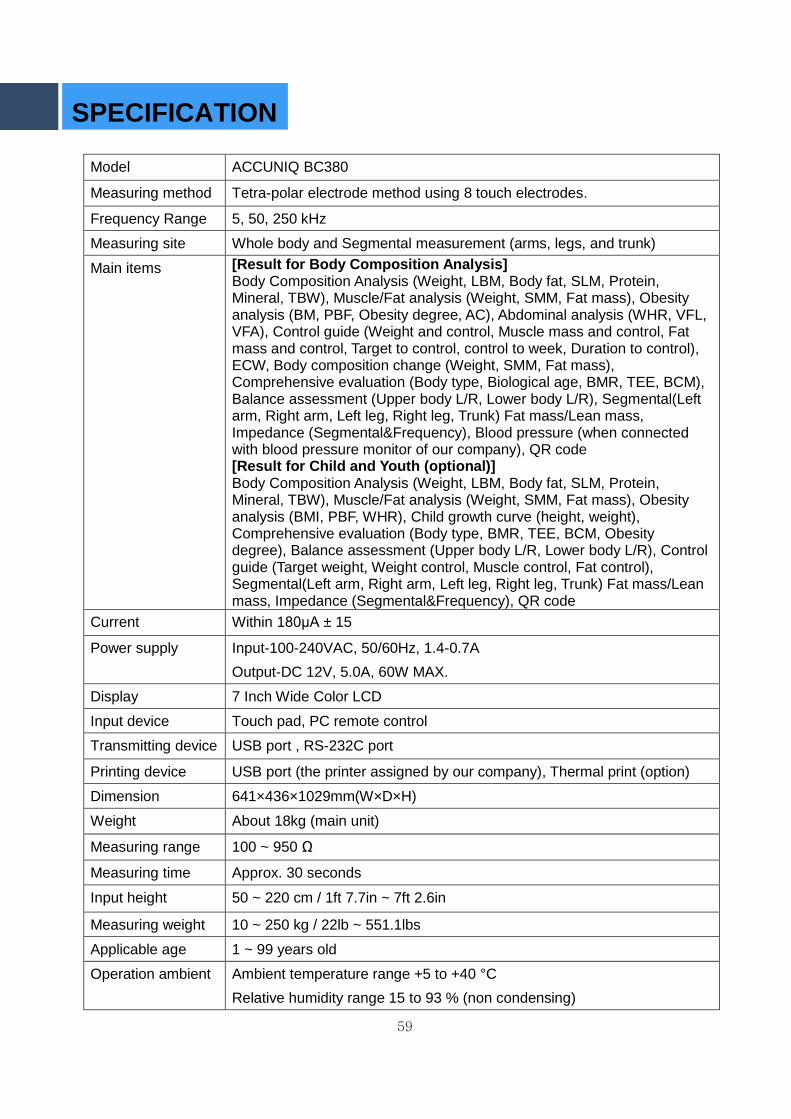
Model ACCUNIQ BC380
Measuring method Tetra-polar electrode method using 8 touch electrodes.
Frequency Range 5, 50, 250 kHz
Measuring site Whole body and Segmental measurement (arms, legs, and trunk)
Main items [Result for Body Composition Analysis] Body Composition Analysis (Weight, LBM, Body fat, SLM, Protein, Mineral, TBW), Muscle/Fat analysis (Weight, SMM, Fat mass), Obesity analysis (BM, PBF, Obesity degree, AC), Abdominal analysis (WHR, VFL, VFA), Control guide (Weight and control, Muscle mass and control, Fat mass and control, Target to control, control to week, Duration to control), ECW, Body composition change (Weight, SMM, Fat mass), Comprehensive evaluation (Body type, Biological age, BMR, TEE, BCM), Balance assessment (Upper body L/R, Lower body L/R), Segmental(Left arm, Right arm, Left leg, Right leg, Trunk) Fat mass/Lean mass, Impedance (Segmental&Frequency), Blood pressure (when connected with blood pressure monitor of our company), QR code [Result for Child and Youth (optional)] Body Composition Analysis (Weight, LBM, Body fat, SLM, Protein, Mineral, TBW), Muscle/Fat analysis (Weight, SMM, Fat mass), Obesity analysis (BMI, PBF, WHR), Child growth curve (height, weight), Comprehensive evaluation (Body type, BMR, TEE, BCM, Obesity degree), Balance assessment (Upper body L/R, Lower body L/R), Control guide (Target weight, Weight control, Muscle control, Fat control), Segmental(Left arm, Right arm, Left leg, Right leg, Trunk) Fat mass/Lean mass, Impedance (Segmental&Frequency), QR code
Current Within 180μA ± 15
Power supply Input-100-240VAC, 50/60Hz, 1.4-0.7A
Output-DC 12V, 5.0A, 60W MAX.
Display 7 Inch Wide Color LCD
Input device Touch pad, PC remote control
Transmitting device USB port , RS-232C port
Printing device USB port (the printer assigned by our company), Thermal print (option)
Dimension 641×436×1029mm(W×D×H)
Weight About 18kg (main unit)
Measuring range 100 ~ 950 Ω
Measuring time Approx. 30 seconds
Input height 50 ~ 220 cm / 1ft 7.7in ~ 7ft 2.6in
Measuring weight 10 ~ 250 kg / 22lb ~ 551.1lbs
Applicable age 1 ~ 99 years old
Operation ambient Ambient temperature range +5 to +40 °C
Relative humidity range 15 to 93 % (non condensing)

60
Atmospheric pressure range 70 kPa (700 mbar) to 106 kPa (1060 mbar)
Storage ambient Ambient temperature range -25 to +70 °C
Relative humidity range lower than 93 % RH
Atmospheric pressure range 70 kPa (700 mbar) to 106 kPa (1060 mbar)
Software name and
version Name: BC380, Version: BC380.K.1.0.00
※ For purpose of improvement, specifications and design are subject to change without notice.

61
WARRANTY
Warranty
Name of product Body Composition Analyzer
Name of model ACCUNIQ BC380
Serial number
Period of warranty Within 1 year from the date of purchase
Date of purchase
Customer Add. Name
Tel.
Dealer (market) Add. Name
Tel.
Note - When you receive this warranty, make sure that the name of the dealer and the
month, day and year of purchase are all completed.
- This warranty will not be reissued, please keep it in a safe place.

62
1. Main Unit Installation For your safety, it is highly recommended that the transporting, unpacking and installation of this product be carried out by two or more people working together.
(1) Product installation components
(2) Unpacking
① Place the box on the floor so that the direction of the arrow on the product box faces upward.
Assembling Instruction
Body Cover M6 plate head
bolt X 2
Main Body
4mm hexagonal
wrench
Adapter and power cable

63
② Remove the packing band and tape with scissors or a knife very carefully so as to prevent
damage to the product.
③ When opening the box and folding the lid, take care not to crush the urethane foam when
removing the product protection materials.

64
(3) Unit Setup
① Two or more workers should remove the product from the box, centering their efforts on the
scale.
② Place the main frame of the product on a flat surface with an average slope of less than 10
degrees as shown in the figure. When erecting the main frame of the product, raise the column as shown in the figure below.

65
③ Make sure that the sides of the vertical column of the frame are aligned at right angles so that
they match with the bottom platform. Make sure that the screw holes on the bottom of the vertical column and the main platform are aligned.

66
④ One person should hold the body’s frame to prevent it from falling, while the other person
removes the packing vinyl from the product. While one person holds the main frame, the other person should use a 4mm hexagonal wrench to insert two M6 bolts into the left and right grooves of the body hinge bracket as shown in the figure.

67
(4) Assembly of body hinge cover
① Remove the body hinge cover in the direction of the arrow as shown in the figure.
② Attach the body hinge cover to the lower part of the vertical column of the body fat analyzer as
shown in the figure, then press on both sides of the body hinge cover to snap it together. (To remove it, please pull both sides apart.)
68
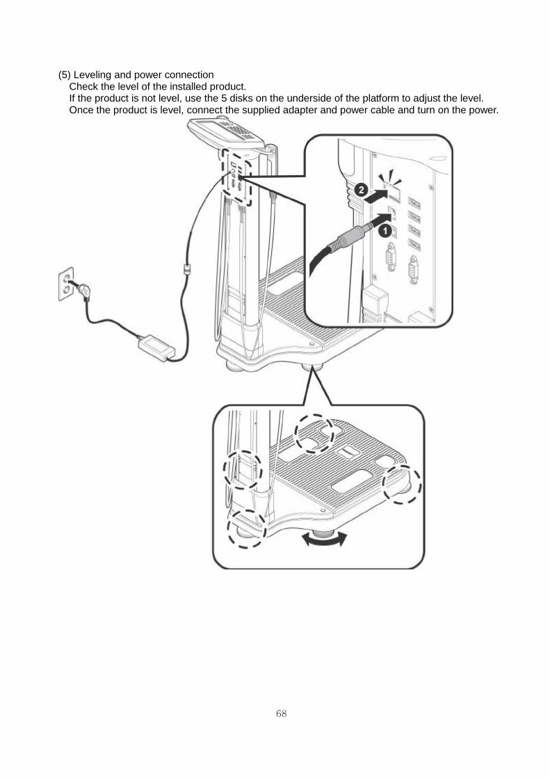
(5) Leveling and power connection
Check the level of the installed product. If the product is not level, use the 5 disks on the underside of the platform to adjust the level. Once the product is level, connect the supplied adapter and power cable and turn on the power.
69
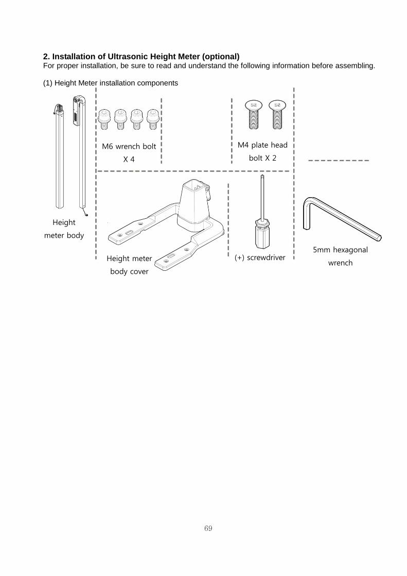
2. Installation of Ultrasonic Height Meter (optional) For proper installation, be sure to read and understand the following information before assembling. (1) Height Meter installation components
Height
meter body
5mm hexagonal
wrench
M6 wrench bolt
X 4
M4 plate head
bolt X 2
(+) screwdriver
Height meter
body cover

70
(2) Preparation before Height Meter installation
① Please turn off the product, and disconnect the adapter jack.
After ensuring the floor is clean, lay vinyl or paper on the floor in order to protect the product when laying it down. Make sure that there are no foreign or sharp objects on the floor, as these may cause damage to the product. Please check the components after opening the height meter box and extensometer body box.
Vinyl (or Paper)

71
(3) Installation of extensometer
① Lay the product on its back as shown. Be careful not to damage the product.
Place a support or thick book as shown in the picture so the LCD does not touch the floor. Place the electrode handle in a safe place so that it does not interfere with the assembly of the product.
② Before attaching the Height Meter to the scales base plate, check the four M6 wrench bolt
housing holes located on the bottom of the scale, and pull out the cable connection from the jack from inside the scales.
72
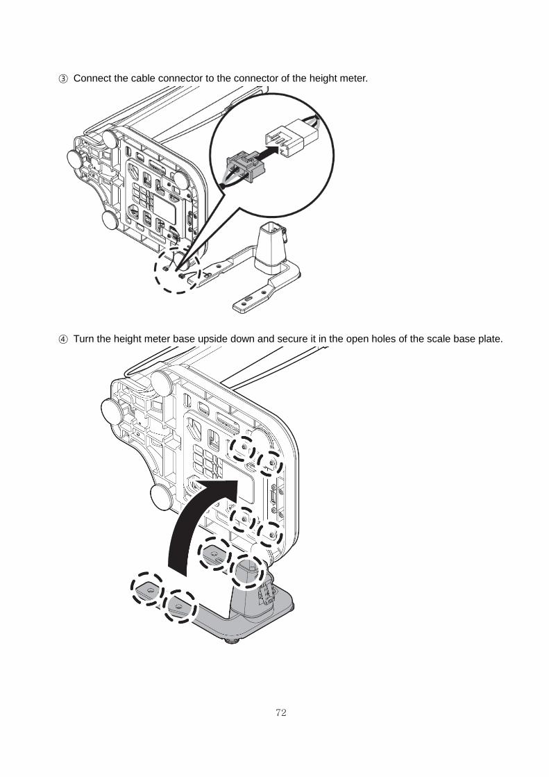
③ Connect the cable connector to the connector of the height meter.
④ Turn the height meter base upside down and secure it in the open holes of the scale base plate.

73
⑤ Secure the M6 wrench bolts to each hole with a 5 mm hexagonal wrench.
⑥ When the extensometer base is installed, place the product on a level surface.
Be careful not to damage the product. Be sure any supports or floor coverings are moved out of the way.

74
⑦ The Height meter body consists of 2 parts in total. Take out two extension parts and remove the
packing vinyl.
⑧ Place the two extension parts side by side on the floor.

75
⑨ When connecting the middle of the upper body to the body base, please position the "D-SUB
connector" in the same direction as the figure. Remove the connector cables from both the upper and lower parts, and connect the cables together.
⑩ Insert the connected cable into the extensometer body, then push the upper and lower parts
together until it clicks.

76
⑪ Fix the two M4 plate head bolts to the left and right holes as shown in the figure using a plus (+)
screwdriver.
Connection of upper and lower parts of the height meter body is completed.
⑫ Raise the locking lever of the body cover as indicated by the arrow in the figure.

77
⑬ As shown in the figure, push the upper part of the rubber pad inside the body cover to move the
height meter body easily. Insert the height meter body into the body cover. (The RS-232C connector at the bottom of the height meter body must be connected to the connector connection jack attached to the stand.)
78
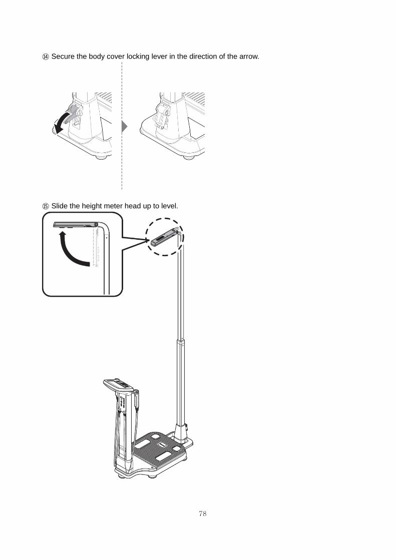
⑭ Secure the body cover locking lever in the direction of the arrow.
⑮ Slide the height meter head up to level.

79
⑯ If the connection of the height meter head is loose, use a flat screwdriver to secure the bolt.
Connect the adapter and turn on the power switch.

80
3. Installation of ankle electrode (optional) For your safety, it is highly recommended that the transporting, unpacking and installation of this product be carried out by two or more people working together. (1) Ankle electrode installation components
(2) Installation of ankle electrode
① Before installing the ankle electrode, turn off the power switch and disconnect the power cable.
Ankle
electrode
4mm hexagonal
wrench
M6 plate head bolt
X 4

81
② Lay the product on its back as shown. Be careful not to damage the product. Please use
supports or a thick book as shown to prevent the LCD from touching the floor. Place the electrode handle in a safe place so that it does not interfere with the assembly.
③ Before attaching the ankle electrode pedestal to the scales base plate, check the cable
connection jack on the scales and the four M6 bolt holes. (1, 2, 3, 4 holes: M4 range bolt and 4mm wrench tool)

82
④ Connect the two connectors on the ankle electrode to the connector jacks on the bottom of the
scales as shown.
⑤ Align the connector jacks, and push them into the hole in the foot platform, and align it with the
M6 bolt locking hole.

83
⑥ Hold the ankle electrode with one hand and secure the ankle electrode to the scale with 4 M6
bolts using a 4 mm hexagonal wrench.

84
⑦ Attach the ankle electrode to the scales and place the product on a level surface.
Be careful not to damage the product. Be sure any supports or floor coverings are moved out of the way.
⑧ Jiggle your ankle electrode to check if it is fixed properly.

85
⑨ Power connection
After assembling the ankle electrode, connect the supplied power cable and the power supply.

86
4. Installation of optional thermal printer For your safety, it is highly recommended that the transporting, unpacking and installation of this product be carried out by two or more people working together. (1) Thermal printer installation components
(2) Installation of thermal printer
① Remove the cover surrounding the LCD of the body fat meter using the minus shape(-) driver as
shown in the figure.
Thermal printer (+) Screwdriver
M3 plate head bolt
X 3

87
② Connect the cable connection jack of the thermal printer to the connector on the rear side so
that it clicks.
③ Align the thermal printer with the groove on the back of the body fat measurement device and
push it horizontally in to place.

88
④ Hold the thermal printer with one hand and insert the M3 plate head bolts into the three holes
with a plus shape (+) screwdriver.
⑤ Thermal printer installation is completed. (To replace the thermal printer’s paper, please refer to
the "Replacing the thermal paper" section in this manual.)

Periodic Check List
Management No.
Item Inspection Subject Requirements Judgment Remarks
Visual Check
Mainframe 1 Enclosure No scratch, crack, deformation and rust
Pass/Fail
2 Labels and panels No peeling and dust Pass/Fail
3 LCD No damage Pass/Fail
4 Electrode No scratch and damage Pass/Fail
Accessories 1 Power cord No scratch and damage Pass/Fail
2 User manual Kept in proper place Pass/Fail
Mechanical Check
Mainframe 1 Keys Smooth operation Pass/Fail
2 Recorder Smooth operation with no abnormal sound
Pass/Fail
3 Touch Screen Smooth operation Pass/Fail
Accessories 1 Power cord Smooth operation and removal
Pass/Fail
Electrical Check
Performance 1 Power supply Screen display upon power-on
Pass/Fail
2 Display No abnormality and flickering
Pass/Fail
3 Printing printing possible Pass/Fail
4 Measurement Proper measurement Pass/Fail
General Judgment Pass/Fail
Model ACCUNIQ BC380 Serial No.
Installation place Date of purchase
Check date Checked by Approved by
Copy this sheet for use If repair is required, write down so in the Remarks column.

Daily Check List
Management No.
Item Inspection Subject Requirements Judgment Remarks
Visual Check
Mainframe
1 Enclosure No scratch, crack,
deformation and rust Pass/Fail
2 Labels and panels No peeling and dust Pass/Fail
3 LCD No damage Pass/Fail
4 Electrode No scratch and damage Pass/Fail
Accessories 1 Power cord No scratch and damage Pass/Fail
2 User manual Kept in proper place Pass/Fail
Mechanical Check
Mainframe
1 Touch Screen Smooth operation Pass/Fail
2 Recorder Smooth operation with no abnormal sound
Pass/Fail
Accessories 1 Power cord Smooth operation and removal
Pass/Fail
Electrical Check
Performance
1 Power supply Screen display upon power-on
Pass/Fail
2 Display No abnormality and flickering
Pass/Fail
3 Printing Waveform printing possible Pass/Fail
4 Measurement Proper measurement Pass/Fail
Other 1 Clock Present date/time Pass/Fail
General Judgment Pass/Fail
Model ACCUNIQ BC380 Serial No.
Installation place Date of purchase
Check date Checked by Approved by
Copy this sheet for use If repair is required, write down so in the Remarks column.

BC380E-20170918 Rev2.0
EUROPEAN REPRESENTATIVE: VITAKO Sp. z o.o. ul. Stanisława Żaryna 7c 02-593 Warszawa, POLAND TEL: +48 505 522 888