
The development and use of a mathematical omni ... · The development and use of a mathematical...
42
The development and use of a mathematical omni- directional dummy for analysing rear-end collisions with non-symmetrical occupant loading Student: Ing. N. Rutjes Report number: MT04.21 Period: November 2003 – November 2004 Institutes: Eindhoven University of Technology, The Netherlands Department of Mechanical Engineering - Vehicle safety Chalmers University of Technology, Sweden Department of Machine and Vehicle Design Committee: Ir. H.J. Cappon (TNO) Dr. J. Davidsson (Chalmers, external supervisor) Dr. Ir. J.A.W. van Dommelen (TU/e, internal supervisor) Prof. Dr. Ir. M.G.D. Geers (TU/e) Prof. Dr. Ir. J.S.H.M. Wismans (TU/e)
Transcript of The development and use of a mathematical omni ... · The development and use of a mathematical...

The development and use of a mathematical omni- directional dummy for analysing rear-end collisions with non-symmetrical occupant loading
Student: Ing. N. Rutjes Report number: MT04.21 Period: November 2003 – November 2004
Institutes: Eindhoven University of Technology, The Netherlands
Department of Mechanical Engineering - Vehicle safety
Chalmers University of Technology, Sweden Department of Machine and Vehicle Design
Committee: Ir. H.J. Cappon (TNO)
Dr. J. Davidsson (Chalmers, external supervisor) Dr. Ir. J.A.W. van Dommelen (TU/e, internal supervisor) Prof. Dr. Ir. M.G.D. Geers (TU/e) Prof. Dr. Ir. J.S.H.M. Wismans (TU/e)

Report Master Thesis N.Rutjes I
Abstract Soft tissue neck injuries caused by rear-end collisions, often called whiplash injuries, have low threat-to-life risk, but they can lead to long-term consequences. Studies to protect humans from neck injuries caused by rear-end collisions are necessary. At Chalmers University of Technology, a mechanical and mathematical sagittal plane dummy, named BioRID II and Madymo BioRID II respectively, were created for analysing rear-end collisions. The accuracy of these dummies for rear-end collisions with non-symmetric impact configurations resulting in a non-symmetric loading of the occupant was unknown. In this thesis, an omni-directional (OD) mathematical dummy model was development, based on the Madymo BioRID II, for the purpose of a dummy comparison with a sagittal plane dummy model. The kinematic performance of this new model, named Madymo BioRID II OD, was tuned by the use of 15 degree oblique rear-end volunteer sled tests, conducted in the Dynamic Restraint Test Facility by TRL. A seat model resembling the seat used in the volunteer sled test was developed. The dummy-seat contact characteristics were obtained by the use of pendulum tests on the seat foams. The need for an omni-directional dummy for analysing rear-end collisions with non-symmetrical occupant loading conditions was investigated by comparing the Madymo BioRID II with the Madymo BioRID II OD. This was done in two different configurations; an oblique rear-end collision and a pure rear-end collision with twisting seat back. The importance of considering twisting seat backs in the design of car seats was demonstrated by a parameter study. It was indicated that the neck injury risk differs between the two dummy models up to 20%. Therefore, for accurate assessment of the neck injury in non-symmetric loading environments, an omni-directional dummy would be desirable.

Report Master Thesis N.Rutjes II
Acknowledgements I want to thank all those who helped me throughout my master thesis, especially: Johan Davidsson, Associated Professor, Department of Machine and Vehicle Design, Chalmers University of Technology, for supervision. Hans van Dommelen, Assistant Professor, Department of Mechanical Engineering, Eindhoven University of Technology, and Hans Cappon, TNO, for their advice on methods and report. Linda Eriksson, Ph.D. student, Department of Machine and Vehicle Design, Chalmers University of technology, for help in creating and modifying the Madymo models. Claire Willis, Associate Researcher, TRL Limited, to make volunteer sled test data available and to help me interpret these data and test environment. Anneloes Dalenoort, TNO, for help with TNO Adviser All the persons of the department Machine and Vehicle Design at Chalmers University of technology for their hospitality and to make me comfortable in the Swedish culture and the world of vehicle safety. Finally, I am grateful to Willemijn and my family for their support and patience, even though I was abroad for a long period.

Report Master Thesis N.Rutjes III
Table of contents Abstract_____________________________________________________________ I
Acknowledgements___________________________________________________ II
Table of contents_____________________________________________________III
1. Introduction______________________________________________________1
1.1 Anatomy of the spine __________________________________________1
1.2 Spine Biomechanics ___________________________________________2
1.3 Mechanical model_____________________________________________3
1.4 Mathematical model ___________________________________________4
1.5 Dummy validation ____________________________________________5
1.6 Aims of this study _____________________________________________5
2. Summary of study 1 and 2 __________________________________________6
2.1 Method _____________________________________________________6
2.2 Results______________________________________________________7
3. General Discussion ________________________________________________8
4. Conclusion ______________________________________________________9
5. References______________________________________________________10

Report Master Thesis N.Rutjes IV
This master thesis report is based on the work contained in two studies, which are appended: 1. Development of an omni-directional Madymo dummy model based on the
BioRID II
Introduction____________________________________________________1
Model and Method ______________________________________________1
Dummy _____________________________________________________1
Seat ________________________________________________________3
Contact between dummy and seat_________________________________4
Evaluation ___________________________________________________6
Results________________________________________________________9
Evaluation ___________________________________________________9
Discussion____________________________________________________13
Conclusion ___________________________________________________14 2. Comparison of the response between an omni-directional and a sagittal plane
dummy model in rear-end impact simulations
Introduction____________________________________________________1
Method _______________________________________________________2
Injury criteria ________________________________________________2
Twisting seat _________________________________________________2
Comparison between sagittal plane and omni-directional dummy model __3
Results________________________________________________________3
Twisting seat _________________________________________________3
Comparison between sagittal plane and omni-directional dummy model __5
Discussion_____________________________________________________7
Conclusion ____________________________________________________8

Report Master Thesis N.Rutjes 1
1. Introduction Rear-end car collisions typically occur in traffic situations with dense traffic and relatively small distance between vehicles in the same lane. At sudden decreases in the traffic tempo, the risk is significant that a driver will start braking too late and will bump into the vehicle in front with some residual speed. Many rear impacts that result in neck injuries occur at low velocity of the impacting car, typically less than 20 km/h (Kahane, 1982; Romilly et al., 1989; Olsson et al., 1990). Eichberger et al. (1996) and Hell and Langwieder (1998) reported that more than 90% and 75%, respectively, of the neck injuries in rear impacts occurred with a velocity difference below 25 km/h. A study by Hell et al. (2003) shows that 43% of the rear-end collisions are with non-symmetric impact configurations, resulting in a non-symmetric loading of car and occupant. The percentage of non-symmetric occupant loadings may even be larger, since a twisting seat back occurs in some pure rear-end collisions. In-depth information about this issue is still unknown. The Abbreviated Injury Scale (AIS) has six levels: AIS 1 (minor injury) to AIS 6 (fatal injury). Neck injuries, often called whiplash injuries or whiplash associated disorders (WAD), are classified as AIS 1 (AAAM 1985). WAD represents a broad set of symptoms, such as neck pain, weakness in the shoulder area, dizziness, headache and memory loss (Spitzer et al.,1995). Although AIS 1 injuries have low threat-to-life risk, these injuries can lead to long-term consequences, which can result in huge societal costs (Nygren, 1984). Therefore, studies to protect humans for neck injuries caused by rear-end collisions are necessary.
1.1 Anatomy of the spine The human spine (figure 1) consists of seven cervical (C1-C7), twelve thoracic (T1-T12) and five lumber vertebrae (L1-L5), connected by soft tissue, inter-vertebral discs, ligaments and muscles, and is supported by the sacrum, which is connected to the pelvic girdle. Except for C1 and C2, the vertebrae have a similar structure, although vertebrae size and angle between the facet joint and the disk varies.
Figure 1: Human spine (adopted from http://www.humankinetics.com/).

Report Master Thesis N.Rutjes 2
The first cervical vertebra, the atlas, can be considered as a ring of bone. The second cervical vertebra, the axis, has a process on the superior side of its body, the dens, and fits in the anterior side of the vertebral foramen of the atlas (figure 2).
Figure 2: Atlas and axis (adopted from Palastanga et al., 1998).
1.2 Spine Biomechanics The human neck motion can be decomposed into four different basic movements (figure 3). Those are flexion (forward bending) and extension (backward bending) about a transverse axis, lateral bending about an anteroposterior axis and axial rotation to the right or left around a vertical axis. Also combinations of those motions are possible.
Figure 3: Basic human motions (adopted from Huelke et al., 1979). Each vertebrae in the spine glides on the vertebrae below guided by oblique facets. At the same time the intervertebral discs deform in different ways corresponding to the type of motion. The discs are stretched on their posterior side in case of flexion, on their anterior side when an extension occurs and on the external side of the curvature during a lateral bending (figure 4). When rotation is applied, the spinal motion creates shear stress within the discs.
Figure 4: Stress in discs during spine rotation (adopted from Hall, 2003).

Report Master Thesis N.Rutjes 3
A mechanical representation of the intervertebral disc is shown in figure 5 (Hall, 2003).
Figure 5: Mechanical representation disc (adopted from Hall, 2003). Volunteer head, neck and T1 motions during a rear-end sled test were explained by Davidsson (2000). At 60 ms, the T1 started to move forward while the head remained stationary relative to inertia until 95 ms. The T1 moved forward faster than the head until 180 ms after impact. The neck developed a limited flexion that lasted between 50 and 130 ms. At 110 ms, the head started to rotate rearward relative to T1. The head continued to rotate rearward until 160 ms. The average T1 was then already rotating forward, which resulted in an increase in neck extension until 190 ms. The rebound started at 190 ms. Figure 6 gives an overview.
Figure 6: Head, neck and T1 motion during rear-end collision (adopted from Davidsson, 2000).
1.3 Mechanical model Tests with crash dummies are used to evaluate risk factors and to evaluate and develop protective systems. Studies have found that the Hybrid III dummy lacks human-like properties in low-speed rear-end impacts (Scott et al.,1993; Davidsson, 2000). In 1992, Svensson and Lövsund developed the RID-neck for use on the Hybrid III. The Hybrid III equipped with the RID-neck predicted volunteer rear-end sled tests better than the Hybrid III with the conventional neck and showed a better simulation of the shearing and the “S” movement as described in the literature. However, the RID-neck did not sufficiently mimic the human neck behaviour during a rear-end impact. The Hybrid III torso was too stiff to mimic the bending of the human thoracic spine (Geigl et al.,1995). The RID neck was updated to the TRID neck by TNO in 1996 but did still not sufficiently represent the response of the human neck (Prasad et al.,1997). A RID3D neck will be developed within EC Whiplash 2 project. Davidsson developed at Chalmers University of Technology the Biofidelic Rear Impact Dummy (BioRID). The BioRID II (figure 7) was a production version developed further compared to the prototype (BioRID I). The BioRID II is equipped with an articulated spine, which resulted in more human-like kinematics compared to the Hybrid III (Davidsson, 2000). The dummy is compared with volunteer sled test with and without head restraint. The construction of the whole spine considers 24
Report Master Thesis N.Rutjes 4
vertebrae. Durable plastic is used for the vertebrae bodies that are connected to each other by pin joints to allow angular motion only in the sagittal plane. Steel washers connect the pins of each vertebra to the adjacent vertebrae pins. These joint pins give a linear torsional spring response.
Figure 7: Mechanical BioRID II dummy (adopted from http://www.cetris.it).
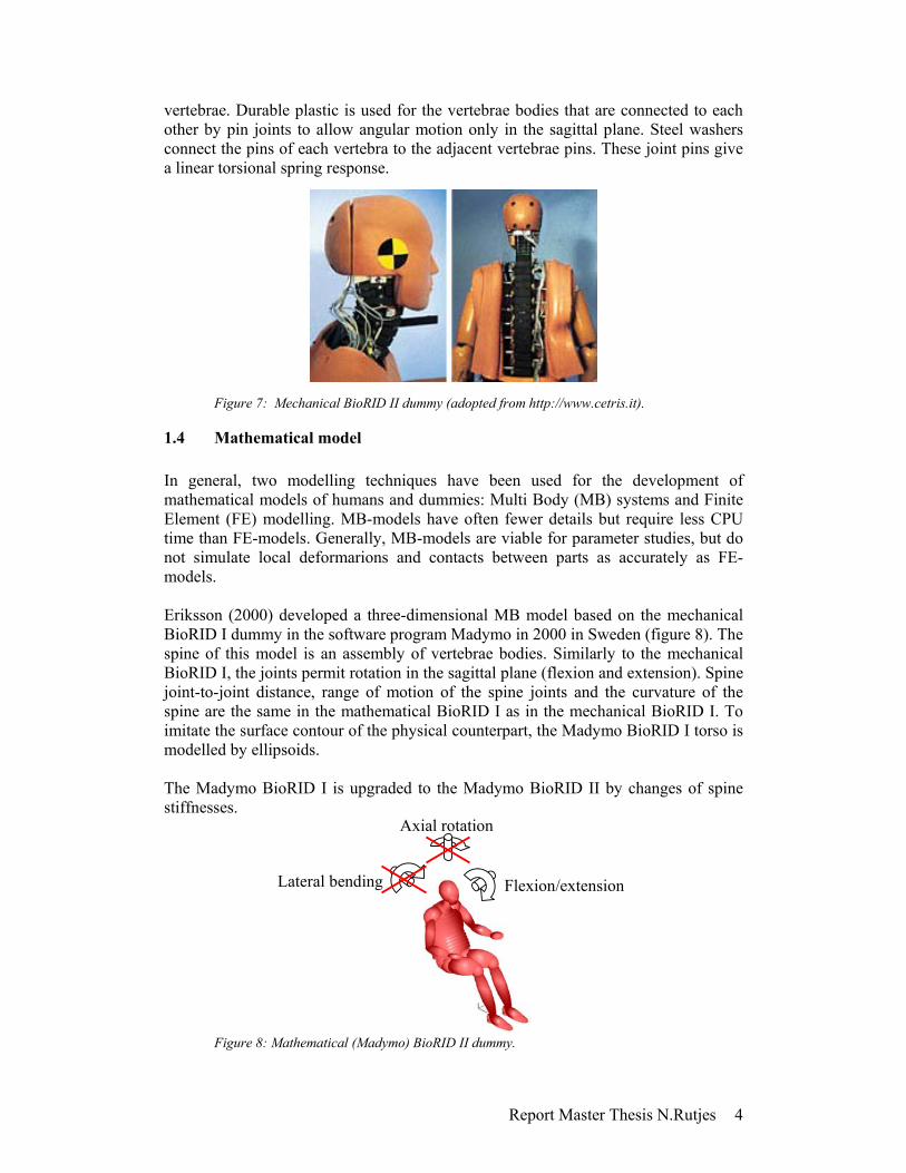
1.4 Mathematical model In general, two modelling techniques have been used for the development of mathematical models of humans and dummies: Multi Body (MB) systems and Finite Element (FE) modelling. MB-models have often fewer details but require less CPU time than FE-models. Generally, MB-models are viable for parameter studies, but do not simulate local deformarions and contacts between parts as accurately as FE-models. Eriksson (2000) developed a three-dimensional MB model based on the mechanical BioRID I dummy in the software program Madymo in 2000 in Sweden (figure 8). The spine of this model is an assembly of vertebrae bodies. Similarly to the mechanical BioRID I, the joints permit rotation in the sagittal plane (flexion and extension). Spine joint-to-joint distance, range of motion of the spine joints and the curvature of the spine are the same in the mathematical BioRID I as in the mechanical BioRID I. To imitate the surface contour of the physical counterpart, the Madymo BioRID I torso is modelled by ellipsoids. The Madymo BioRID I is upgraded to the Madymo BioRID II by changes of spine stiffnesses.
Figure 8: Mathematical (Madymo) BioRID II dummy.
Flexion/extension Lateral bending
Axial rotation

Report Master Thesis N.Rutjes 5
1.5 Dummy validation Cadavers are used to study the gross motions between adjacent vertebrae. However, larger peak-head angular displacements have been obtained in frontal impact tests with cadavers than with volunteers (Wismans et al., 1987) and the preperation of cadavers has shown to influence the kinematic performances (Geigl et al., 1994). Cadavers cannot simulate the mechanical properties of living tissue and are less viable for the study of the pathology of soft tissue neck injuries. To take the effect of muscle activity into account, the mechanical BioRID versions are validated by volunteer sled tests. The Madymo BioRID I model was validated against the Mechanical BioRID I by Eriksson (Eriksson, 2000). During the first 150 ms of the simulated rear-end impacts, the Madymo BioRID I predicted the T1 and head x-acceleration (forward-backward) fairly well, while the z-acceleration (upward-downward) were poorly predicted. The Madymo BioRID I was neither validated for the rebound phase of the crash, nor against out-of-position sled tests. The mechanical BioRID II is an update of the mechanical BioRID I, aimed at improving its biofidelity (Eriksson, 2002). The corresponding mathematical model, the Madymo BioRID II, was based on the Madymo BioRID I model but spine stiffness and damping, torso shape and mass distribution were tuned. The Madymo BioRID II predicted the head, T1 and pelvis x- and z-accelerations well in a comparison with the Mechanical BioRID II. However, the comparison was too limited to serve as a thoroughly validation of the Madymo BioRID II. Neither of the Madymo BioRID versions can mimic hyperextension properly.
1.6 Aims of this study The aims of this thesis are:
• to create and evaluate a mathematical omni-directional dummy model • to investigate the need for an omni-directional dummy for analysing rear-end
collisions with non-symmetrical occupant loadings

Report Master Thesis N.Rutjes 6
2. Summary of study 1 and 2 2.1 Method The Madymo BioRID II OD was created in study 1 based on the Madymo BioRID II from the Madymo 6.1 database. The mass and size of all the bodies of the Madymo BioRID II OD were equivalent to the Madymo BioRID II, but the connections between the vertebrae bodies were modified in order to allow motion in all directions. The stiffness properties for the added degrees of freedom were adopted from the literature. The kinematic performance of the Madymo BioRID II OD was tuned to fit the measured response of a series of 15 degree oblique rear-end volunteer sled tests. These tests were conducted in the Dynamic Restraint Test Facility by TRL. The dummy-seat contact in the model was simplified as ellipsoid-plane contact to minimise the CPU-time. The top layers of the seat foam were modelled as flat planes (figure 9) and the foam characteristics were obtained by the use of pendulum tests. TRL collected raw data such as film analyses and accelerometer data of a 15 degree offset sled tests (Willis and Hynd, 2004) and made these available for this thesis. The displacements of head and T1 markers were used to calculate corridors for the body linear and rotational displacements. The filtered accelerometer output was used to define the accelerometer corridors. Tuning of the model (dummy and seat) was done by the use of TNO Adviser, a software tool for stochastic model analysis (Hoof et al, 2004). Furthermore, the influence of the dummy parameters associated with lateral bending and axial rotation were compared with the parameters associated with dummy position and seat properties.
Figure 9: Madymo BioRID II OD in seat model. In study 2, the need for an omni-directional dummy for analysing rear-end collisions with non-symmetrical occupant loading conditions was investigated by comparing the existing sagittal plane dummy model (Madymo BioRID II) with the omni-directional model (Madymo BioRID II OD). This was done for two different configurations; an oblique rear-end collision and a twisting seat back.

Report Master Thesis N.Rutjes 7
2.2 Results It was not possible to tune the chosen parameter values of the model so that all the Madymo BioRID II OD output curves were entirely between the volunteer corridors. Close approximations to the volunteer corridors were however possible. The model (dummy and seat) was tuned and a reasonable kinematic response was obtained. The spine properties associated with flexion/extension were not tuned. The crash pulse had the largest influence on the dummy output. This was desirable since this was the reference parameter. Two other important parameters were the dummy initial position in x-direction and in axial rotation. The dummy initial position was known to be an important factor in volunteer sled tests, also demonstrated by Welcher and Szabo (2000). The influence of the stiffness of the seat back foam was undesired. It was shown that the range of simulations in which the Madymo BioRID II OD was applicable was limited as a result of the inaccuracy of the dummy-seat contact definition. The comparison between the Madymo BioRID II and the Madymo BioRID II OD started with a pure rear-end simulation. High similarity between the outputs of the two dummy models was expected, since the dummy model properties associated with flexion/extension were identical. It was shown that the differences were negligible. In the second comparison between the Madymo BioRID II and the Madymo BioRID II OD, the two dummy models were seated in a TRL seat model and exposed to a 15-degree oblique rear-end crash pulse. The difference of maximum NIC value between the two dummies was 20%. The head y-displacement and axial rotation of the Madymo BioRID II OD were a better approximation of the volunteers of the 15-degree oblique rear-end TRL sled test compared to the response of the Madymo BioRID II. In the third comparison, the two Madymo dummy models were seated in the TRL seat model with twisting capacities and exposed to a pure rear-end pulse. The twisting motion of the seat back resulted in an aside movement of the Madymo BioRID II in total and in an axial rotation of the Madymo BioRID II OD realised by spine joint rotations. This resulted in a 10% difference in maximum NIC value. The variations of a twisting motion of the seat back in pure rear-end simulations with the Madymo BioRID II OD resulted in a variation of the expected neck injury. The neck injury risk was assessed by the use of the maximum Neck Injury Criterion (NIC) and varied between 4.6 and 10.4 m2/s2. Therefore, the relevance of considering a twisting seat back during the design of a safe car seat was indicated. The parameter with the highest influence on the NIC was the start time of the twisting seat back motion.

Report Master Thesis N.Rutjes 8
3. General Discussion The aim of study 1 was to develop a mathematical omni-directional dummy model, named Madymo BioRID II OD, to investigate its benefits compared to a sagittal plane dummy model. Since a total validation and model construction improvements were beyond of the scope of this study, the range of simulations in which this new dummy could be used was limited. Especially since it was shown in study 1 that the influence of the seat back stiffness had a high influence compared to the dummy spine properties. Nevertheless, it was possible to use the dummy model in the comparison, such like study 2, since these model test environments were showing similarity with that of the Madymo BioRID II OD evaluation. Methods to increase the range of simulations in which this new dummy could be applied were identified. The validation could have a larger time window and more different test environments, like a range of impact velocities and impact directions. Also aspects of the model construction may be improved, such as the design of the shoulder, to obtain an equal response of the mathematical dummy models compared to the mechanical model. The seat model could be improved by replacing the current representation of the seat foams as layers by modelling it as FE part. The accuracy of the size and shape of the contact area between dummy and seat will increase, especially in other test environments then the one used for the evaluation. Nevertheless, the CPU time will increase. The maximum rotation of the seat back of 7 degrees resulted in a variation in maximum NIC values demonstrating the relevance of considering twisting seat backs in the design of safe car seats. The cause of the twisting motion could be determined in the future, for example by analyzing the effect of the initial position variation of the occupant or the non-symmetry of the seat back construction. It was possible that larger differences between the two dummy models would have been found in other test environments, for example out-of-position where a non-symmetric initial dummy position is created without changing the initial spine joint rotations. This is not studied in this thesis, since changes in the initial position of the complete dummy were resulting in unacceptable changes in contact forces between dummy and seat and floor compared to simulations of the validation. Study 1 showed that initial position of the dummy created by changes of the initial spine joint rotations will influence its kinematic response. The need for an omni-directional dummy was not be defined by a comparison with the sagittal plane dummy, but to enable such out-of-position simulations. The NIC is used as indicator for the neck injury risk in this study, since the Madymo BioRID II was evaluated for the parameters included in this criterion. Other neck injury criteria are suggested for rear-end collisions by other researchers (Heitplatz et al., 2003) and it could be considered to include these criteria in future validations of the BioRID models.

Report Master Thesis N.Rutjes 9
It is difficult to quantify the necessary differences in predicted neck injury risk in a comparison between two dummy models, such as study 2, in order to indicate that an omni-directional dummy is needed. Nevertheless, the obtained difference of 20 % in NIC between the two dummies indicated that the inaccuracy of the injury prediction by the use of a sagittal plane dummy could be unacceptable in rear-end collisions with non-symmetric occupant loading. Investments in more research for analyzing rear-end collisions with non-symmetric occupant loadings are recommended. For example by creating a mechanical volunteer sled test seat that is able to simulate a large range of collisions resulting in non-symmetric occupant loadings and a similar mathematical model that is validated with high accuracy. The seat should have a smaller influence on the kinematic response of the dummy or volunteer than the seat used in the TRL sled test. If the dummy models are validated by a number of volunteer tests resulting in non-symmetric occupant loading, possibly with construction improvements of the mathematical model, a dummy comparison with high accuracy is possible. With this knowledge, an investment in a mechanical omni-directional dummy could be considered.
4. Conclusion A first version of a mathematical omni-directional rear-end dummy model (Madymo BioRID II OD) was created. Improvements are desirable if the dummy model is going to be used in a larger range of applications, for example changes in dummy and seat model structure and a more precise evaluation within a larger range of test conditions. Nevertheless, parameter studies with this dummy model are currently possible with approximate test environments compared to the evaluation conditions of the dummy. The sagittal plane dummy model showed a difference up to 20 % in predicted neck injury risk compared to the omni-directional dummy model in simulations with non-symmetric occupant loading conditions. A dummy with such an inaccuracy in injury prediction is considered to be unacceptable, so an omni-directional dummy would be desirable for these conditions. Furthermore, the importance of considering twisting seat backs in the design of safe car seats was shown by its influence on the neck injury risk.

Report Master Thesis N.Rutjes 10
5. References AAAM (1985), The Abbreviated Injury Scale – 1985 Revision, American Association for Automotive medicine, Des Plaines, IL, USA. Berkson, M.H., Nachemson, A., Schultz. A.B. (1979), Mechanical properties of human lumber spine motion segments - Part 2: responces in compression and shear, J. Biomech. Eng., 101:53. Bostrom, O., Fredriksson, F., Haland, Y., Jakobsson, L., Krafft, M., Lovsund, P, Muser, M., Svensson, M.Y. (2000), Comparison of car seats in low speed rear end impacts using the BioRID dummy and the new neck injury criterion (NIC), Accident analysis and prevention, Vol. 32, pp. 321-328 Davidsson, J. (2000), Development of a Mechanical Model for Rear impacts: Evaluation of Volunteer Responses and Validation of the Model, Ph.D. Thesis, Department of Machine and Vehicle Design, Chalmers University of Technology, Sweden, ISBN 91-7197-924-7. Dvorak, L., Panjabi, M.M. (1987), Functional anatomy of the alar ligaments, Spine, 12:183. Eichberger, A., Geigl, B., Moser, A., Fachbach, B., Steffan, H., Hell, W., Langweider, K. (1996), Comparison of Different Car Seats regarding Head-neck Kinematics of Volunteers During Rear-end Impact, Proc. of the International IRCOBI Conference, pp. 153-164. Eriksson, L. (2000), Mathematical Modelling of Low-Speed Rear-End Impacts: Development and Validation of MBS-Models, and Influence of Risk Factors on NIC, Licentiate Thesis, Department of Machine and Vehicle Design, Chalmers University of technology, Sweden. Eriksson, L. (2002), Development and performance of the Madymo BioRID II, Chalmers University of Technology, Autoliv, Sweden. Gabriel, K. R. (1971), The biplot graphical display of matrices with applications to principal component analysis. Biometrika, 58, 453–467. Geigl, B.C., Steffan, H., Leinzinger, R.P., Muhlbraue, M., Bauer, G. (1994), The movement of head and cervical spine during rear-sled impact, Proc. of the International IRCOBI Conference, pp 127-137. Geigl, B.C., Steffan, H., Dippel, C., Muser, M.H., Walz, F., Svensson, M.Y. (1995), Comparison of Head-Neck Kinematics During Rear-end Impact Between Standard Hybrid III, RID Neck, Volunteers, and PMTO’s, Proceedings of 1995 International IRCOBI Conference on the Biomechanics of Impacts, September 16-18, Brunnen, Switzerland, pp. 261-270.

Report Master Thesis N.Rutjes 11
Hall, S. (2003), Basic Biomechanics, Fourth Edition, Mc Graw Hill, USA. Hayes, W.C., Carter, D.R. (1976), The effect of marrow on energy absorption of trabecular bone, Presented at the 22nd annual meeting of the orthopedic research society, New Orleans. Hell, W., Langwieder, K. (1998), Reported Soft Tissue Neck Injuries After Rear-End Car Collisions. Procedings of 1998 International IRCOBI Conference on the Biomechanics of Impacts, September 16-18, Göteborg, Sweden, pp 261-274. Hell, W., Hopfl, F., Langwieder, K., Lang, D. (2003), Cervical spine distortion injuries in various car collision directions and injury incidence of different car types in rear-end collisions. IRCOBI Conference, Lisbon, Portugal. Heitplatz, F., Sferco, R., Fay, P., Reim, J., Kim, A., Prasad, P. (2003), An evaluation of existing and proposed injury criteria with various dummies to determined their ability to predict the levels of soft tissue neck injury seen in real world accidents, ESV 2003, Paper 504. Hoof, J. van, Dalenoort, A., Griotto, G (2004), ADVISER: A software tool for model quality rating and stochastic analyses, TNO, 2004 JSAE Annual Congress, paper 20045478. Huelke, D., Moffatt, E., Mendelsohn, R., Melvin, J. (1979), Cervical Fractures and Fracture Dislocations – An Overview, SAE, Congress and Exposition, Cobo Hall, Detroit, USA Jager, M.K.J. de (1996), Mathematical Head-Neck Models for Acceleration Impacts, Eindhoven University of Technology, ISBN 90-386-0347-9 Kahane, J.C. (1982), An evaluation of Head Restraints – Federal Motor Vehicle Safety Standard 202, Report DOT HS-806, National Technical Information Service NHTSA, Springfield, VA 22161, USA. Lessley, D., Crandell, J., Shaw, G., Kent, R., Funk, J. (2003), Normalizing technique for developing corridors from individual subject responses, Proceeding of the 31st International workshop Injury biomechanics research, San Diego. McGlashen, K.M., Miller, J.A.A, Schultz A.B., Andersson, G.B.J. (1987), Load displacement behavior of the human lumbo-sacral joint, J.Orthop. Res., 5(4):488. Miller, J.A.A., Schmatz, C., Schultz, A.B., (1988), Lumbar disc generation: correlation with age, sex, and spine level in 600 autopsy specimens, Spine, 12(2):173. Moroney, S.P., Schultz, A.B., Miller, J.A.A., Andersson, G.B.J. (1988), Load-displacement properties of lower cervical spine motion segments, J. Biomech., 21(9):767. Nygren, Å. (1984), Injuries to car occupants – Some aspects of the interior safety of cars. Acta Oto-Laryngologica. Supl. 395.

Report Master Thesis N.Rutjes 12
Olsson, I., Bunketorp, O., Carlsson, G. Gustafsson, C., Planath, I., Norin, H., Ysander, L. (1990), An In-depth Study of Neck Injuries in Rear-end Collisions, Proc. of the International IRCOBI Conference, pp 269-280. Panjabi, M.M., Summer, D.J., Pelker, R.R., Videman, T., Friedlaender, G.E., Southwick, W.O. (1986), Three dimensional load displacement curves due to forces on the cervical spine, J. Orthop. Res., 4:152. Palastanga, N., Field, D., Soames, R. (1998), Anatomy & Human Movement – Structure and Function, Third Edition, BH, UK. Panjabi, M.M. (1997), New findings about the Mechanism of Whiplash Injury, North American Congress on Biomechanics, Clemson University, SC., USA. Pearcy, M.J., Tibrewal, S.B. (1984), Axial rotation and lateral bending in the normal lumbar spine measured by three dimensional radiography, Spine, 9(6):582. Prasad, P., Kim, A., Weerappuli, D.P.V. (1997), Biofidelity of Anthropomorphic Test Devices for rear Impacts. SAE paper 973342, Proceedings of 41th Stapp Car Crash Conference, November 13-14, Orlando, Florida, USA, pp. 387-415. Roberts, A.K., Carroll J.A. (2003), Dummy development to evaluate spine injuries – Final report, TRL project report PR/SE/079/03. Romilly, D.P., Thomson, R.W., Navin, F.P.D., Macnabb, M.J. (1989), Low Speed Rear-end Impacts and the Elastic Properties of Automobiles, Proc. of the 12th International technical Conference on Enhanced Safety of Vehicles, pp 1199-1205. Scott, M.W., McConnell W.E., Guzman, H.M., Howard, R.P., Bomar, J.B., Smith, H.L., Benedict, J.V., Raddin, J.H., Hatsell, C.P. (1993), Comparison of Human and ATD Head Kinematics during Low-Speed Rearend Impacts, SAE 930094, Society of Automotive Engineers, Warrendale, PA. Spitzer, W., Skovron, M.L., Salmi, R., Cassidy, D., Duranceau, J., Suissa, S., Zeiss, E. (1995), Scientific Monograph of the Quebec Task Force on Whiplash-Associated Disorders: Redefining “ Whiplash” and its management. Spine, Supplement, Vol. 20, No. 8S. Svensson, M.Y. (1993), Neck-injuries in rear-end car collisions – Sites and biomechanical causes of the injuries, test methods and preventive measures, Departure of Injury prevention, Göteborg, Sweden ISBN 91-7032-878-1. Szabo T and Welcher J (1996), Human Subject Kinematics and Electromyographic Activity During Low Speed Rear Impacts, Proceedings of the 40th Stapp Conference 1996. Tencer, A.F., Allen, B.L., Ferguson, R.L. (1985), A biomechanical study of thoracolumbar spinal fractures with bone in the canal, Part 1, The effect of laminectomy, Spine, 10(6):580.

Report Master Thesis N.Rutjes 13
TNO (2001), Madymo Theory Manual Version 6.0 TNO (2004) Advisers V1.4 - user’s guide Welcher, J.B., Szabo, T.J. (2000), Relationship between seat properties and human subject kinematics in rear impact test, Biomechanical Research and testing, LLC, USA. White, A.A. Panjabi, M.M. (1987), Clinical Biomechanics of the spine, J.B. Lippincott Company, Philadelphia, USA, ISBN 0-397-50388-1. Willis, C., Hynd, D. (2004), TRL rear impact and oblique rear impact dummy biofidelity requirements, EEVC WG12. Wismans, J. Philippens, M., van Oorschot, E., Kallieris, D., Matters, R. (1987), Comparison of Human Volunteer and Cadaver Head-Heck Response in Frontal Flexion, SAE paper no. 872194, Proceedings of 31st Stapp Car Crash Conference, 1-13. Yamamoto, I., Panjabi, M., Crisci, J., Oxland, T. (1989), Normal movements of the lumbar spine, Spine.

Study 1
Development of an omni-directional Madymo dummy model based on the BioRID II
Rutjes, N.

Study 1 N.Rutjes 1
Introduction The mechanical Biofidelic Rear Impact Dummy, the BioRID II, is a crash test dummy, which was developed at Chalmers University of Technology. The BioRID II is equipped with an articulated spine, which resulted in more humanlike kinematic response in low-speed rear impact sled tests compared to the Hybrid III (Davidsson, 2000). Eriksson developed a three-dimensional model based on the mechanical BioRID II in the software program Madymo. The spine of this model is an assembly of segments, which represent the human vertebrae bodies. Similar to the mechanical BioRID II, the spine joints only permit motion in the sagittal plane (Eriksson., 2000 and 2002). The accuracy of these sagittal plane dummy models is unknown in crash situations with non-symmetric occupant loadings. The aim of this study is to modify the existing 3-D mathematical model of the BioRID II for the design of an omni-directional dummy model. This will allow for a comparison between the two models to provide recommendations for future dummy development.
Model and Method Dummy The mathematical omni-directional dummy model (Madymo BioRID II OD) was based on the BioRID II model from the Madymo 6.1 database. The mass and size of all the bodies of the Madymo BioRID II OD were equivalent to the Madymo BioRID II, but the connections between the vertebrae bodies were modified in order to make motion possible in all directions. The vertebrae bodies in the Madymo BioRID II OD were connected by spherical joints (three possible rotations around x-,y- and z-axis) and the stiffness and damping were added by applying cardan restraints. The spine model stiffnesses, in the form of loading functions for flexion/extension, were adopted from the Madymo BioRID II. The spine model stiffnesses for lateral bending and axial rotation were based on the data reported in the literature, see table 1 (Berkson et al, 1979, Dvorak et al., 1988, Hayes et al., 1989, de Jager, 1996, McGlashen et al, 1987, Miller et al, 1988, Moroney et al, 1988, Panjabi et al, 1986, Peacey et al, 1984, Tencer et al., 1985, White and Panjabi, 1987, Yamamoto et al. 1989). The range of rotation determines the location of the asymptote in the loading functions. The slope of the loading function around the neutral point of the rotation was chosen to equal the desired stiffness of the joints (figure 1). Damping was added to the Madymo BioRID II OD spine joints to prevent instability. The Madymo BioRID II for two-dimensional analyses had non-linear damping-velocity functions, but the use of damping-velocity functions in multi body analyses with omni-directional joint rotations was not possible in the 6.1 version of Madymo. For this reason, the damping in the Madymo BioRID II OD was defined by a constant damping coefficient (figure 1).

Study 1 N.Rutjes 2
Table 1: Average spine properties adopted from literature.
−5 0 5 10−200
−100
0
100
200Joint Load flexion/extension BioRID II = BioRID II OD
rotation angle [degree]
stat
ic lo
ad to
rque
[Nm
]
LumbarThoraxCervical
−400 −200 0 200 400−8
−6
−4
−2
0
2
4
6
8Joint Damping all directions
rotation velocity [degree/s]
dam
ping
torq
ue [N
m]
L & T BioRID IIC BioRID IIL & T BioRIDII ODC BioRIDII OD
−10 −5 0 5 10−200
−100
0
100
200Joint Load lateral bending BioRID II OD
rotation angle [degree]
stat
ic lo
ad to
rque
[Nm
]
LumbarThoraxCervical
−10 −5 0 5 10−200
−100
0
100
200Joint Load axial rotation BioRID II OD
rotation angle [degree]
stat
ic lo
ad to
rque
[Nm
]
LumbarThorax 1Thorax 2Cervical 1Cervical 2
Figure 1: Loading and damping functions of spine joints of BioRID II OD model.
The stiffness of the original Madymo BioRID II shoulder joint was not based on measurements on the mechanical dummy, but tuned to create a desired influence of the arm motion on the head and T1 kinematics. Because of the fact that the seat in this study was different and results in a different arm motion compared to the studies of Eriksson (2000), the shoulder stiffness was corrected for the Madymo BioRID II and the Madymo BioRID II OD equally.

Study 1 N.Rutjes 3
Seat The kinematic performance of the Madymo BioRID II OD was tuned by the use of oblique rear-end volunteer sled tests. All tests were conducted in the Dynamic Restraint Test Facility at TRL, using a test set-up designed to replicate previous rear-impact volunteer testing conducted at TRL but with a 15° offset to represent an oblique impact (Willis and Hynd, 2004). The seat used for the tuning of the Madymo BioRID II OD was based on the UN/ECE Regulation 44 (1998) specification as illustrated in figure 2. The seat was geometrically similar to the R44 seat, except that the height of the seatback was increased to support the shoulders of the volunteers (to a height of 590 mm above the CR line of the R44 bench). The seat back was padded with stiff polyethylene foam, 70 mm thick and with a density of 30 kg/m3 (EV30, manufactured by Zotefoam). The seat base was padded with standard high-density, closed cell, polyurethane foam (CONFOR CF-45, manufactured by AeroE-A-R.) with a density of 70 kg/m3 and a thickness of 140 mm. An adjustable (fore-aft and vertical) head restraint was attached to the seat to limit gross motion of the occupant's head. The head restraint was padded with 50 mm of CONFOR foam and approximately 70 mm of very soft packing foam. Volunteers were restrained using a 3-point belt.
Figure 2: Side view of R44 seat foam layers (left) and side view of head restraint foam (right), both adopted from Willis and Hynd (2004).
The dummy-seat contact was simplified as ellipsoid-plane contact to minimise the CPU-time to make large parameter studies possible. Therefore, only the top layers of the seat and head restraint foams were modelled in Madymo (figure 3). A cylinder was placed under the seat cushion to prevent penetration of the lower legs into the seat.
Figure 3: TRL seat model in Madymo.
CONFOR Foam
Packing Foam
Impact direction

Study 1 N.Rutjes 4
The modelling of the foam layers as flat planes with force-penetration curves was an approximation for perpendicular penetration in the foam. The effect of the restraint force between the head and head restraint caused by foam shape was taken into account by adding it to the friction factor of the head restraint. The factor was adjusted in order to make the head rotation in extension correct. This was considered plausibly, since the spine properties in this direction were adopted from the evaluated Madymo BioRID II and were not change in this study. The values for the damping and friction of the seat surfaces were adopted from a seat model used in earlier studies with the Madymo BioRID II (Eriksson, 2000).
Contact between dummy and seat A pendulum test was carried out at the Chalmers University of Technology, Department of Machine and Vehicle systems, to define force-penetration curves of the foams of the seat back and head restraint of the seat used in the volunteer tests (figure 4). An impactor contacted the foams perpendicular to its surface with a round flat area with a diameter of 152 mm. The impactor mass was 33.4 kg. The loading rate was similar to the velocity of the sled in the volunteer test.
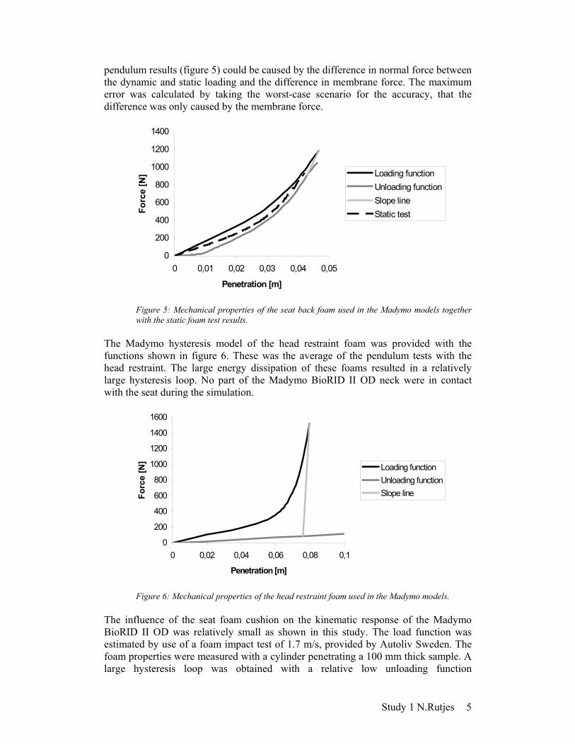
Figure 4: Pendulum test facility. The dynamic penetration-force curve of the seat back was determined. A hysteresis model (TNO, 2001) was used to simulate the reaction forces in Madymo between the seat foam and the Madymo BioRID II OD. The loading and unloading functions were defined as the average of three penetration-force curves. The so called hysteresis slope line connected the loading with the unloading functions. The reaction force of the seat back was calculated by scaling the foam forces from the pendulum test with the contact areas between the dummy and the seat back. The Madymo hysteresis model of the seat back foam was provided with the functions shown in figure 5. The error made in the loading function scaling could maximally result in a too high model seat back stiffness of 16 %. This is calculated by comparing the membrane forces in the foam, caused by the deformed foam around the impactor front surface, and the normal force, produced by the compressed foam. They were estimated by comparing the static foam information received from the foam manufacturer with the pendulum test results. The static pressures in different compression points were generated with test procedure ASTM D3575. This was a procedure where the upper surface of the sample was smaller than the press cylinder surface, so no membrane forces occurred during the test. The difference between the static information and
wires
foam
frame
impactor
Study 1 N.Rutjes 5
pendulum results (figure 5) could be caused by the difference in normal force between the dynamic and static loading and the difference in membrane force. The maximum error was calculated by taking the worst-case scenario for the accuracy, that the difference was only caused by the membrane force.
0
200
400
600
800
1000
1200
1400
0 0,01 0,02 0,03 0,04 0,05
Penetration [m]
Forc
e [N
] Loading functionUnloading functionSlope lineStatic test
Figure 5: Mechanical properties of the seat back foam used in the Madymo models together with the static foam test results.
The Madymo hysteresis model of the head restraint foam was provided with the functions shown in figure 6. These was the average of the pendulum tests with the head restraint. The large energy dissipation of these foams resulted in a relatively large hysteresis loop. No part of the Madymo BioRID II OD neck were in contact with the seat during the simulation.
0
200
400
600
800
1000
1200
1400
1600
0 0,02 0,04 0,06 0,08 0,1
Penetration [m]
Forc
e [N
]
Loading functionUnloading functionSlope line
Figure 6: Mechanical properties of the head restraint foam used in the Madymo models.
The influence of the seat foam cushion on the kinematic response of the Madymo BioRID II OD was relatively small as shown in this study. The load function was estimated by use of a foam impact test of 1.7 m/s, provided by Autoliv Sweden. The foam properties were measured with a cylinder penetrating a 100 mm thick sample. A large hysteresis loop was obtained with a relative low unloading function

Study 1 N.Rutjes 6
corresponding to the energy absorption as described by the foam producer (www.earsc.com). The Madymo hysteresis model of the seat cushion foam was defined by the functions shown in figure 7.
0
500
1000
1500
2000
2500
0 0,02 0,04 0,06 0,08 0,1
Penetration [m]
Forc
e [N
] Loading functionUnloading functionSlope line
Figure 7: Mechanical properties of the seat cushion foam used in the Madymo models.
Evaluation TRL made raw data such as film analyses and accelerometer output available of the 15 degree offset sled tests with 8 volunteers (figure 8). Estimates of average responses (displacements, rotations and accelerations) were required for the evaluation of the Madymo BioRID II OD. Corridors were determined for linear and rotational displacements and linear accelerations. The upper corridor was the mean plus one standard deviation and lower corridor was the mean minus one standard deviation. The standard deviation was calculated at each point in time, not the maximum standard deviation appearing in the whole time window. To eliminate sharp peaks, the corridors were approximated by linear curves between picked node points.
Figure 8: Diagram to illustrate test set-up adopted from Willis and Hynd (2004).

Study 1 N.Rutjes 7
All displacements and rotations of the body parts were expressed with respect to the seat by the use of a right-handed Cartesian coordinate system that was attached to the seat. Therefore, lateral measurements were parallel to the seat head restraint (y-direction), fore-aft measurements perpendicular to the seat head restraint (x-direction), etc. The accelerations were expressed in a right-handed Cartesian coordinate system in the corresponding rigid body orientation, so for example initially head z- direction was defined as positive downward, positive head x- direction forward, etc. All simulation outputs were expressed a similar set of coordinate systems as ones used for the volunteer data. The average curve was defined for all the data as the average for each point in time (simple average), except for the head acceleration output. For this quantity, a normalisation technique was used to create a characteristic average. A simple average corridor lacks the characteristic shape of the curves as a result of time mismatch between the individual volunteer head acceleration curves caused by small differences between volunteers, for example volunteer mass, size and initial position. Errors in the average were only visible in the upper and lower corridors because of its relative high value of the ratio mean/std. By taking the average on the time-normalised corridors, errors caused by time mismatch were excluded (Lessley et al., 2003). This method required a common characteristic shape of all the volunteer outputs and was fulfilled by the similarity of the individual normalised curves. To demonstrate the method, the calculated average for the normalised head x-acceleration corridor is given in figure 9.
0 0.05 0.1 0.15
0
2
4
6
8
Time [s]
Acc
[g]
TRL volunteer acceleration Head X
Simple averageVolunteers
0 20 40 60 80 100
0
2
4
6
8TRL volunteer acceleration Head X norm
(Time/max Time)x100% [%]
Acc
[g]
Norm averageVolunteers
Figure 9: Difference between simple average (left) and normalised average (right) of volunteer head x-acceleration.
Model parameters were defined to influence the dummy initial positions, the damping, friction and stiffness of seat and dummy and the pulse (table 2).

Study 1 N.Rutjes 8
Parameter Name Dummy spine stiffness Thorax flexion/extension Stif_Tx
Thorax lateral bending Stif_Ty Thorax axial rotation upper part Stif_Tz1 Thorax axial rotation lower part Stif_Tz2 Lumbar flexion/extension Stif_Lx Lumbar lateral bending Stif_Ly Lumbar axial rotation Stif_Lz Cervical flexion/extension Stif_Cx Cervical lateral bending Stif_Cy Cervical axial rotation upper part Stif_Cz1
Cervical axial rotation lower part Stif_Cz2 Thorax and lumbar all directions Damp_spine_TL Dummy spine damping Cervical all directions Damp_spine_C
Dummy shoulder joint stiffness Fric_Shoulder Dummy friction arm-body Fric_dummy_sur
Flexion/extension Ini_Pos_x Lateral bending Ini_Pos_y
Dummy initial position
Axial rotation Ini_Pos_z Seat foam stiffness Cushion Stif_C Back Stif_B Head restraint Stif_H Seat foam damping Head restraint and back Damp_H/B Cushion Damp_C Seat foam friction Back and cushion Fric_B/C Head restraint Fric_H Sled Pulse Pulse
Table 2: Parameters seat & dummy model. Three sets of 100 Madymo simulations with randomly chosen values for all the parameters within ranges (table 3) were conducted by the use of TNO Adviser, a software tool for stochastic model analysis (van Hoof et al, 2004). For each output curve of each simulation, the approach of the TRL volunteer corridor was defined by the use of corridor indicators (criteria), defined as the ratio of the numbers of points of the output curve that exceed the corridor with respect to the total number of points. For the first simulation set, the value range of each model parameter in dummy and seat was chosen as large as the expected deviation in the TRL volunteer test or the inaccuracy of the parameter value approximation. All the parameters adopted from the Madymo BioRID II were provided with a relatively very small range. All the parameter ranges of the dummy and seat that were obtained from the literature or originated from the pendulum foam tests or volunteer sled test set up were chosen relatively large.
Model parameters range Madymo BioRID II OD in seat Simulation set Originally present
BioRID II Newly added to
dummy Seat Sled
pulse Initial position
1 – 20% to +20% As large as accuracy 2 - – 20% to +20% Spine joints * 3 - -50% to +350% -2.5% to +2.5% - -
Ranges are defined with respect to parameter value * = Resulting in initial head rotation -7 to +7 degrees and/or initial head CoG displacement -25 to +25 mm Table 3: Parameters and ranges.

Study 1 N.Rutjes 9
The kinematic performance of the Madymo BioRID II OD was not expected to be totally equivalent with the kinematic performance of the volunteers, considering the fact that the Madymo BioRID II OD was an upgrade of a mathematical approach of a mechanical dummy. The first simulation set had to indicate the best possible approximation of the volunteers’ response. The influence of the dummy parameters associated with lateral bending and axial rotation were compared with the parameters associated with dummy position and seat properties in the second and third simulation set. All the parameters ranges in the second simulation set were defined in proportion. The third simulation set was provided with extreme large ranges for all the dummy parameters, which were added in this study, and extreme small range for the seat parameters.
Results Evaluation By the use of the computer program TNO Adviser, the maximum of each corridor criterion result of the first simulation set was determined and the Madymo BioRID II OD was tuned (picture 10). One of the tools used for the tuning was a selection of simulations, which all had a high score on each criterion (best 40% at each criterion). The mean value and standard deviation of each input parameter of selected simulation group was calculated and compared to the mean value and standard deviation of input parameters of the total set. Parameters with a difference in mean and increased standard deviation were adjusted. Also the correlation between each parameter and each volunteer corridor criteria was determined. The Madymo BioRID II OD spine properties in flexion/extension were not tuned.
Figure 10: Approximation TRL volunteers. It was fount to be impossible to tune the chosen parameter values so that all the model output curves were exactly inside the volunteer corridors. Since the approximation of the curves to the corridors was not taken into account caused by limitations of the program tool, each of the low rated model outputs of the tuned Madymo BioRID II OD was compared to the volunteer corridors manually to predict the accuracy of the model.

Study 1 N.Rutjes 10
A part of the Madymo BioRID II OD head and T1 displacement curves in x- direction (figure 11) were outside the volunteer corridors. Nevertheless, high similarity of the model curve shapes was noticed compared to the volunteer corridors. Madymo BioRID II OD head and T1 z-displacements were far out the volunteer corridors, but a similar behaviour was measured by Roberts and Carroll (2003) in a pure rear-end sled test with the mechanical BioRID II positioned in a seat similar to the one used in the Madymo model. A large part of the model head y-displacement curve (figure 11) was within the corridor, but the model plot shape was not corresponding with the volunteer data. The volunteer motion in this direction was limited until the moment that the head touches the head restraint, and increased faster compared to the model in the period with head-to-head restraint contact. The difference in head y-displacement between model and volunteers was possibly caused by the difference in axial head rotations. The T1 flexion/extension rotation curve (figure 12) was not within the volunteer corridor, but the approximation of model curve shape was reasonable. The maximum value of the average of the volunteers was twice as much as the maximum of the model curve. However, since the volunteer T1 rotation measurement was inaccurate and much higher T1 rotations are measured with the mechanical BioRID II compared to the mechanical Hybrid III (Davidsson et. al., 2000), this model output deviation was accepted. The axial head rotation (figure 12) differs between the volunteers and the dummy model. This was possibly caused by the absence of muscles in the model in combination with a possibly high influence of active muscle tension on the axial volunteer head rotation. In this model, the muscle activity was included as human body stiffness. Since a clear reason for this volunteer head behaviour was absent, the axial volunteer head rotation during the first 100ms after impact was not considered with the Madymo BioRID II OD. Nevertheless, the unexpected approximation to the volunteer axial head rotation was possible (figure 11). Similar in all simulations with correct axial head rotation output, was the initial position of dummy head, namely rotated counter clockwise (1 to 2,4 degree). A control run where only the initial head rotation was changed resulted indeed in a head rotation curve within volunteer corridors, but the shape was different from the volunteer mean curve. Therefore, the criterion for tuning was changed in Adviser from a corridor check to a slope check around 0.125 s after impact, since this gave a better reproduction of the stiffness similarities between the volunteers and the model. The deviation of the BioRID II OD pelvis y-acceleration (figure 13) compared to the volunteer corridors starts at 70 ms. Since contact friction forces between the seat and the dummy were generated the y-acceleration of the dummy in this seat model, restraint forces by the foam shape were probably not modelled properly. The acceleration of the T1 in z-direction (figure 13) was correct during the first 100 ms, but incorrect in the period 100 – 150 ms. This was the result of an incorrect straightening of the Madymo BioRID II OD spine compared to the volunteers, also visible in the plot with z-displacements.

Study 1 N.Rutjes 11
0 0.05 0.1 0.15
−150
−100
−50
0
Dis
plac
emen
t x [m
m]
Displacement with respect to seat
Head CoG BioRID II ODT1 CoG BioRID II ODCorridors Head VolunteersCorridors T1 Volunteers
0 0.05 0.1 0.15−100
−50
0
Dis
plac
emen
t y [m
m]
Head CoG BioRID II ODCorridors Head Volunteers
0 0.05 0.1 0.15−20
0
20
40
Time [s]
Dis
plac
emen
t z [m
m]
Head CoG BioRID II ODT1 CoG BioRID II ODCorridors Head VolunteersCorridors T1 Volunteers
Figure 11: Displacements predicted by the Madymo BioRID II OD and volunteer corridors.
0 0.05 0.1 0.15−30
−25
−20
−15
−10
−5
0
5
Rot
atio
n fle
xion
/ext
ensi
on [d
egre
e]
Rotation with respect to seat
Head BioRID II ODT1 BioRID II ODCorridors Head VolunteersCorridors T1 Volunteers
0 0.05 0.1 0.15−10
−5
0
5
10
15
Time [s]
Axi
al r
otat
ion
[deg
ree]
Head BioRID II ODCorridors Head Volunteers
Figure 12: Rotations predicted by the Madymo BioRID II OD and volunteer corridors.
0 0.05 0.1 0.15−20
0
20
40
60
80
Acc
x [m
/s2 ]
Acceleration expressed in corresponding rigid body coordinate system
Head BioRID II ODPelvis BioRID II ODT1 BioRID II ODCorridors Head VolunteersCorridors Pelvis VolunteersCorridors T1 Volunteers
0 0.05 0.1 0.15−40
−30
−20
−10
0
10
Acc
y [m
/s2 ]
Head BioRID II ODPelvis BioRID II ODT1 BioRID II ODCorridors Head VolunteersCorridors Pelvis VolunteersCorridors T1 Volunteers
0 0.05 0.1 0.15−40
−20
0
20
40
Time [s]
Acc
z [m
/s2 ]
Head BioRID II ODPelvis BioRID II ODT1 BioRID II ODCorridors Head VolunteersCorridors Pelvis VolunteersCorridors T1 Volunteers
Figure 13: Accelerations predicted by the Madymo BioRID II OD and volunteer corridors.

Study 1 N.Rutjes 12
The results of the second and third simulation set were analysed by the use of a ReDundancy Analysis (RDA) distance biplots (figure14 and 15). The descriptors were a representation of the criterion results, the variables were the input parameters. A biplot, proposed by Gabriel (1971), displays the observations and variables in the same plot, in a way that it represents their joint relationships. The axes in the biplot represent the principal components. It is possible to interpret the plotted vectors using the rules provided by the TNO Advisers user’s guide (table 4).
Descriptors Variables Vector length Range of model criterion result Influence on model Angle between a descriptor vector and variable vector
0 or 180 degree = high correlation 90 degree = no correlation
Table 4: Rules for interpretation of RDA distance plot, adopted from TN0 (2004)
Figure 14: Influences of the four most important model inputs and eleven most important model outputs in set 2
A similar variation of each seat and parameter was allowed in the second simulation set together with a small variation in dummy initial position to define the importance of all the model parameters (figure 14). The pulse was found to have the largest influence. This was desirable it this was the reference parameter. Two other important parameters were the dummy position in x-direction and in axial rotation. Dummy initial position was known to be an important factor in volunteer sled tests, also reported by Welcher and Szabo (2000). The influence of the stiffness of the seat back foam was undesired, since this model was created to tune the dummy properties and not the properties of the seat. The required accuracy of the seat parameters to minimize the influence of the seat parameters was defined by the use of simulation set 3 (figure 15). A large variation (range of 400%) of the dummy parameters and a small variation (range of 5%) of the other parameters were allowed. A maximum inaccuracy of the dummy-seat contact in the model could be defined by the comparison of a large number of pendulum laboratory tests (variation impact speed) with similar pendulum model runs. The RDA biplot of set 3 shows that the seat parameters variations will have minor influence on the dummy behaviour, even though, the influence of the seat back stiffness was not eliminated entirely.

Study 1 N.Rutjes 13
Figure 15: Iinfluences of the six most important model inputs in simulation set 3.
Discussion The aim of this study was to create an omni-directional dummy model for the purpose of investigating the need of an omni-directional dummy under non-symmetric occupant loading conditions. Since a complete validation was beyond of the scope of this study, the range of simulations in which the Madymo BioRID II OD was applicable was limited. It could be improved by future studies on the aspects discussed below. The Madymo BioRID II OD was based on the tuned Madymo BioRID II in the loading phase. Therefore, the Madymo BioRID II OD is only valid for the first 150 ms, corresponding to the loading phase. Szabo (1996) showed that this phase is important in neck injury generation, but a discussion between researchers is still going on about this issue. Validation in a longer time window will possibly increase the range of simulations in which the Madymo BioRID II OD is applicable. Including of the seat belt is possibly necessary. Currently it is necessary to tune of the shoulder stiffness in the dummy model for each seat model. A similar response of the mathematical dummy models compared to the mechanical BioRID II in a larger range of arm motion would be desirable. This study showed that the model output had a reasonable correlation with the volunteer corridors, but the change of shoulder stiffness should always be taken into account in further studies. The foam of the seat was characterised for only one particular velocity, similar to the maximum volunteer sled velocity. The behaviour of some seat foams were rate dependent, so future simulations are only accurate with a similar sled pulse as used in this study.

Study 1 N.Rutjes 14
The influence of the initial dummy position in x-direction, the initial axial rotation and the seat back stiffness were shown to be more important than the dummy spine properties if variations of all seat and dummy parameters were equal and changes in initial position were small. This influences the model limitations, since the seat parameters were defined with low accuracy. To be able to carry out simulations with the Madymo BioRID II OD positioned in a seat with other properties than the one used in this study, it is necessary to have a TRL seat model with a higher accuracy (5% variation or less) for a better validation. This requirement was not fulfilled in this study, caused by the inaccuracy of the contact area definition between the seat and the dummy and the scaling of the pendulum results. The contact definition could be improved with a foam pendulum test simulation. Furthermore, the seat model could be improved by replacing the planes of the seat foams with FE parts. The accuracy of the shape and size of the contact area between dummy and seat will increase, also in other test environments then the one used for the evaluation. However, the CPU time will increase. The torque generated by the damping was approximately 20 % of the total torque generated in the spine joints. The maximum difference between the non-linear damping-velocity functions and the linear damping-velocity functions were approximately 25 % at a range of rotation velocities from 0 to 400 degrees/sec (figure 1). The maximum rotational velocities in the dummy model spine joints were around 200 degree/sec. The difference in spine damping functions between the Madymo BioRID II and the Madymo BioRID II OD results in a maximum difference of 5 % in total spine model torque. A comparison between the Madymo BioRID II and the Madymo BioRID II OD in a pure rear-end crash simulation showed high similarity. This study contained more then 300 simulations, while none of these simulations were interrupted. Furthermore, none of the parameter variations were resulting in unexpected extreme output variations. The model can therefore be assumed to be stable.
Conclusion A first version of a mathematical omni-directional rear-end dummy model (Madymo BioRID II OD) was created. Parameter studies with this dummy model are currently possible with test environments that are comparable to this study.
Study 2
Comparison of the response between an omni- directional and a sagittal plane dummy
model in rear-end impact simulations
Rutjes, N.

Study 2 N.Rutjes 1
Introduction Neck injuries caused by rear-end collisions, often called whiplash injuries are classified as AIS 1 (AAAM, 1985). Although AIS 1 injuries have low threat-to-life risk, these injuries can lead to long-term consequences, which can result in huge societal costs (Nygren,1984). Chalmers University of Technology created a sagittal plane dummy, named BioRID II, for analysing rear-end collisions (Davidsson, 2000). A study by Hell et al. (2003) shows that 43% of the rear-end collisions are with non-symmetric impact configurations, resulting in a non-symmetric loading of car and occupant (figure 1).
Figure 1: Impact configuration for rear-end car-car collisions with injury (adopted from Hell et al., 2003).
During rear-end collisions, the seat back could twist (see figure 2). This also results in non-symmetric occupant loadings, even in pure rear-end collisions. Detailed in-depth information about this issue is still lacking. A twisting seat back motion could possibly be caused by a non-symmetric initial position of the occupant or by non-symmetric seat back constructions to allow for the integration of side airbags. The aim of this study is to estimate the need for an omni-directional dummy for analysing rear-end collisions with non-symmetrical occupant loadings. This is investigated by comparing the kinematics of a sagittal plane dummy model (BioRID II) with that of an omni-directional model (BioRID II OD) in Madymo, which is developed and evaluated in study 1. Also, the importance of considering twisting seat backs in the design of safe car seats is investigated.

Study 2 N.Rutjes 2
Figure 2: Example of a twisted seat back after a real rear-end collision, adopted from Dutch Accident Research Team.
Method Injury criteria The differences between the two dummies and the effect of twisting seats were expressed in neck injury risk variations. The Neck Injury Criterion (NIC) was chosen, since its correlation with injury was showed for the loading phase of a rear-end collision (Bostrom et al., 2000). Furthermore, the Madymo BioRID II and Madymo BioRID II OD have been evaluated on the parameters associated with this injury criterion (Eriksson et al, 2000, study 1). The tolerance value for the NIC that corresponds with injury is 15 m2/s2. The maximum NIC is defined as: ( )2
xrelxrelms150firstmax va0.2maxNIC +⋅= (1) An omni-directional NIC was suggested in order to study the effect of including dummy kinematics in y-direction in the NIC (formula 2). The assumption was made that relative accelerations and velocities in x- and y- directions were resulting in a similar influence on the neck injury risk.
+++⋅= 2
yrel2
xrel2
yrel2
xrelms150firstmaxOD vvaa0.2maxNIC (2)
The rela and relv are the relative T1 to head acceleration and velocity, respectively. Directions are established by the subscripts x and y.
Twisting seat The importance of considering twisting seat backs in the design of car seats was determined by a set of simulations. These simulations were based on the Madymo BioRID II OD and TRL seat model used for the evaluation in study 1. Two modifications were made: a joint was added to the seat back in order to make a twisting motion of the seat back possible and the impact direction was changed to simulate a pure rear-end collision. Parameter associated with twisting seat back Range Maximum rotation of the seat back 1-7 degree Stiffness of the seat back rotation joint 0.1 – 10 Nm/rad Starting time of the rotation 25 –75 ms after impact
Table 1: Twisting seat parameter ranges.

Study 2 N.Rutjes 3
Parameters associated with the twisting motion were the starting time of the rotation, the maximal rotation of the seat back and the model joint rotation stiffness of the seat back. The parameter value ranges (see table 1) were chosen as large as the model applicability permits, since they were not adopted from a real car seat. The highest and lowest maximum NIC values occurring within the parameter ranges were determined by the use of the software tool Adviser. To increase the understanding of the model, a relation was established between the NIC and the parameters associated with the twisting motion of the seat.
Comparison between sagittal plane and omni-directional dummy model The need for an omni-directional dummy for analysing rear-end collision with non-symmetric occupant loadings was investigated by comparing the Madymo BioRID II and the Madymo BioRID II OD in a pure rear-end crash situations and two crash situations resulting in a non-symmetric occupant loading: a 15 degree oblique rear-end and a pure rear-end with twisting seat back. All simulations were based on the model used in the evaluation in study 1. Also the available volunteer corridors of the 15 degree oblique rear-end sled tests are used (study 1).
Results All the acceleration, displacement, rotation and NIC plots in this study were expressed using the code shown in table 2.
Twisting seat A maximum NIC value was calculated for each pure rear-end simulation with the Madymo BioRID II OD, while the parameter values of the twisting seat backs were varied within the defined range (see table 1). The maximum NIC value varied between 4.6 and 10.4 m2/s2. Maximum values of the omni-directional NIC were calculated for each simulation and differed not more then 1.5 % compared to the maximum NIC values. This was a result of the low T1 and head y-velocity and acceleration in these simulations. The parameter with the highest influence on the NIC was the start time of the twisting motion. This was indicated by the RDA biplot of the simulation set (figure 3). The NIC varies due to the fact that the timing of T1 x-acceleration and not the head x-acceleration was shifted (figure 4)
Figure 3: RDA distance plot for the Madymo BioRID II OD in the TRL seat model with a twisting seat back.

Study 2 N.Rutjes 4
Colour Blue Red Cyan Magenta Green Black Information Head T1 Pelvis NIC NICOD Volunteers
Table 2: Line colour code for acceleration, displacement and rotation plots.
0 0.05 0.1 0.15−150
−100
−50
0
Dis
p x
[mm
]
Displacement with respect to seat
0 0.05 0.1 0.15
−40
−20
0
Dis
p y
[mm
]
0 0.05 0.1 0.15−20
−10
0
10
20
Dis
p z
[mm
]0 0.05 0.1 0.15
−20
−10
0
Rot
flex
/ext
[deg
ree]
Time [s]
Rotation with respect to seat
0 0.05 0.1 0.15−15
−10
−5
0
5
Time [s]
Rot
axi
al [d
egre
e]
0 0.05 0.1 0.15
0
20
40
60
Acc
x [m
/s2 ]
Acceleration expressed in corresponding rigid body coordinate system
0 0.05 0.1 0.15
−10
0
10
20
Acc
y [m
/s2 ]
0 0.05 0.1 0.15
−20
0
20
Acc
z [m
/s2 ]
0 0.05 0.1 0.150
5
10
Time [s]N
IC [m
2 /s2 ]
Neck Injury
Figure 4: Kinematics of the Madymo BioRID II OD in the TRL seat model with a twisting seat back, resulting in low NICmax value (dashed line) compared to the situation resulting in high NICmax value (solid line).
0 0.05 0.1 0.15−150
−100
−50
0
Dis
p x
[mm
]
Displacement with respect to seat
0 0.05 0.1 0.15
−40
−20
0
Dis
p y
[mm
]
0 0.05 0.1 0.15−20
−10
0
10
20
Dis
p z
[mm
]
0 0.05 0.1 0.15
−20
−10
0
Rot
flex
/ext
[deg
ree]
Time [s]
Rotation with respect to seat
0 0.05 0.1 0.15−15
−10
−5
0
5
Time [s]
Rot
axi
al [d
egre
e]
0 0.05 0.1 0.15
0
20
40
60
Acc
x [m
/s2 ]
Acceleration expressed in corresponding rigid body coordinate system
0 0.05 0.1 0.15
−10
0
10
20
Acc
y [m
/s2 ]
0 0.05 0.1 0.15
−20
0
20
Acc
z [m
/s2 ]
0 0.05 0.1 0.150
5
10
Time [s]
NIC
[m2 /s
2 ]
Neck Injury
Figure 5: Dummy model outputs in the TRL seat model with a pure rear-end pulse. Comparison between Madymo BioRID II (dashed line) and Madymo BioRID II OD (solid line).

Study 2 N.Rutjes 5
Comparison between sagittal plane and omni-directional dummy model The comparison between the Madymo BioRID II and the Madymo BioRID II OD started with a pure rear-end simulation. The two dummy models were positioned similarly in the TRL seat. The crash pulse was similar as the one used in the evaluation of the Madymo BioRID II OD. High similarity of the outputs of the two dummy models was expected. Figure 5 shows that differences were negligible. In the second comparison between the Madymo BioRID II and the Madymo BioRID II OD, the two dummy models were placed in a TRL seat model and exposed to a 15-degree oblique rear-end crash pulse. These simulations were similar to the one used for the evaluation of the Madymo BioRID II OD. Differences were perceptible for T1 x-acceleration, head, T1 and pelvis y-acceleration, head displacement in y-direction and axial head rotation (figure 6 and 7). The difference of maximum NIC value between the two dummies was 20 %. The y-displacement and the axial rotation of the Madymo BioRID II OD head were a better approximation of the volunteers of the 15-degree oblique rear-end TRL sled test then the response of the Madymo BioRID II (figure 8). In the third comparison between the Madymo BioRID II and Madymo BioRID II OD, the dummy models were seated in the TRL seat model with twisting capacities and exposed to a pure rear-end acceleration pulse. Parameters associated with the twisting motion were set to the values shown in table 3. The twisting motion of the seat back resulted in an aside movement of the Madymo BioRID II in total and in a relative axial rotation of the Madymo BioRID II OD realised by spine joint rotation (see figure 9 and 10). The maximum x-acceleration of the head and T1 occurred at the same time for the two dummy models, but the maximum value differed. This resulted in a 10% difference in maximum NIC value. The maximum accelerations and displacements in y-direction of the Madymo BioRID II were twice as large compared to the Madymo BioRID II OD. Parameter associated with twisting seat back Range Maximum rotation of the seat back 7 degree Stiffness of the seatback rotation joint 2.3 Nm/rad Start timing of the rotation 30 ms after impact
Table 3: Twisting seat parameters.

Study 2 N.Rutjes 6
Figure 6: Frontal view of dummy models in TRL seat model subjected to 15 degree oblique rear-end pulse 150 ms after impact. Comparison between the Madymo BioRID II (left) and Madymo BioRID II OD (right).
0 0.05 0.1 0.15−150
−100
−50
0
Dis
p x
[mm
]
Displacement with respect to seat
0 0.05 0.1 0.15
−40
−20
0
Dis
p y
[mm
]
0 0.05 0.1 0.15−20
−10
0
10
20
Dis
p z
[mm
]
0 0.05 0.1 0.15
−20
−10
0
Rot
flex
/ext
[deg
ree]
Time [s]
Rotation with respect to seat
0 0.05 0.1 0.15−15
−10
−5
0
5
Time [s]
Rot
axi
al [d
egre
e]
0 0.05 0.1 0.15
0
20
40
60
Acc
x [m
/s2 ]
Acceleration expressed in corresponding rigid body coordinate system
0 0.05 0.1 0.15
−10
0
10
20
Acc
y [m
/s2 ]
0 0.05 0.1 0.15
−20
0
20A
cc z
[m/s
2 ]
0 0.05 0.1 0.150
5
10
Time [s]
Abs
NIC
[m2 /s
2 ]
Neck Injury
Figure 7: Dummy model outputs in the TRL seat model with a 15 degree oblique rear-end pulse. Comparison between Madymo BioRID II (dashed line) and Madymo BioRID II OD (solid line).
0 0.05 0.1 0.15
−40
−20
0
Displacement with respect to seat
Dis
p y
[mm
]
Time [s]0 0.05 0.1 0.15
−20
−10
0
10
Acc
y [m
/s2 ]
Acceleration
Time [s]0 0.05 0.1 0.15
−15
−10
−5
0
5
Time [s]
Rot
axi
al [d
egre
e]
Rotation with respect to seat
Figure 8: Dummy head model response in the TRL seat model with a 15 degree oblique rear-end pulse. Comparison between Madymo BioRID II (dashed line) and Madymo BioRID II OD (solid line) with y-displacement volunteer corridor (left), axial rotation line slope check (middle) and y-acceleration volunteer corridor (right)

Study 2 N.Rutjes 7
Figure 9: Frontal view of dummy models in TRL seat model subjected to a pure rear-end pulse and twisting seat back, 150 ms after impact. Ccomparison between Madymo BioRID II (left) and Madymo BioRID II OD (right)
0 0.05 0.1 0.15−150
−100
−50
0
Dis
p x
[mm
]
Displacement with respect to seat
0 0.05 0.1 0.15
−40
−20
0
Dis
p y
[mm
]
0 0.05 0.1 0.15−20
−10
0
10
20
Dis
p z
[mm
]
0 0.05 0.1 0.15
−20
−10
0
Rot
flex
/ext
[deg
ree]
Time [s]
Rotation with respect to seat
0 0.05 0.1 0.15−15
−10
−5
0
5
Time [s]
Rot
axi
al [d
egre
e]
0 0.05 0.1 0.15
0
20
40
60
Acc
x [m
/s2 ]
Acceleration expressed in corresponding rigid body coordinate system
0 0.05 0.1 0.15
−10
0
10
20
Acc
y [m
/s2 ]
0 0.05 0.1 0.15
−20
0
20
Acc
z [m
/s2 ]
0 0.05 0.1 0.150
5
10
Time [s]
NIC
[m2 /s
2 ]
Neck Injury
Figure 10: Dummy model outputs in the TRL seat model with a pure rear-end pulse and twisting seat back, Comparison between Madymo BioRID II (dashed line) and Madymo BioRID II OD (solid line).
Discussion The maximum rotation of the seat back of 7 degrees resulted in such a variation in maximum NIC values that the relevance of twisting seat back studies for safe car seat designs is evident. The cause of the twisting motion could be determined in the future, for example by analyzing the effect of the initial position variation of the occupant or the non-symmetry of the seat back construction. It was possible that larger differences between the two dummy models would have been found in other test environments, for example out-of-position where a non-symmetric initial dummy position is created without changing the initial spine joint rotations. This is not studied in this thesis, since changes in the initial position of the complete dummy were resulting in unacceptable changes in contact forces between

Study 2 N.Rutjes 8
dummy and seat and floor compared to simulations of the validation. Study 1 showed that initial position of the dummy created by changes of the initial spine joint rotations will influence its kinematic response. The need for an omni-directional dummy was not be defined by a comparison with the sagittal plane dummy, but to enable such out-of-position simulations. The z-accelerations of the Madymo BioRID II and Madymo BioRID II OD were showing relatively large fluctuation, which are possibly unrealistic. However, they are not included in the NIC in the dummy comparison of this study and the head and T1 accelerometer outputs in the other directions are not showing unexpected fluctuation. The influence of the fluctuations in z-accelerations on the correctness of this study is expected to be small. The Madymo BioRID II OD only shows a difference between the NIC and the NICOD in the 15-degree oblique rear-end simulation, but not in the simulation with the twisting seat backs. An Omni-directional neck injury criterion could be required if lateral displacement of the head with respect to the T1 occurs. More research is required for these conditions, since this difference showed that the expected soft tissue neck injury could increase if the lateral kinematics are taken into account. The NIC is used as indicator for the occurring neck injury in this study, since the Madymo BioRID II was evaluated for this criterion. Alternative neck injury criteria are suggested for rear-end collisions by other researchers (Heitplatz et al., 2003) and it could be considered to include this criteria in future validations of the BioRID models. It is difficult to quantify the necessary differences in predicted neck injury risk in a comparison between two dummy models, such as study 2, in order to indicate that an omni-directional dummy is needed. Nevertheless, the obtained difference of 20 % in NIC between the two dummies indicated that the inaccuracy of the injury prediction by the use of a sagittal plane dummy could be unacceptable in rear-end collisions with non-symmetric occupant loading.
Conclusion A difference in kinematic response of the Madymo BioRID II and Madymo BioRID II OD was measured in simulations where the dummies were exposed to a 15-degree oblique rear-end pulse and a pure rear-end pulse with twisting seat back. This resulted in a different neck injury assessment between the two dummy models. The maximum NIC value differs up to 20%, being larger for the Madymo BioRID II OD. A dummy with such an inaccuracy in injury prediction is considered to be unacceptable, so an omni-directional dummy would be desirable for these conditions. The comparison of the two dummy models in a pure rear-end simulation resulted in a similar kinematic response. The importance of considering twisting seat backs in the design of safe car seats was shown by its influence on the expected neck injury.