The Design Projects for the Simulation-Based Design Course...The Design Projects for the Simulation...
12
Paper ID #14644 The Design Projects for the Simulation-Based Design Course Dr. Xiaobin Le P.E., Wentworth Institute of Technology Associate professor, Ph.D, PE., Department ofMechanical Engineering and Technology, Wentworth In- stitute of Technology, Boston, MA 02115, Phone: 617-989-4223, Email: [email protected], Specialization in Computer Aided Design, Mechanical Design, Finite Element Analysis, Fatigue Design and Solid Me- chanics Prof. Ali Reza Moazed, Wentworth Institute of Technology Ali R. Moazed is a Professor in the Mechanical Engineering and Technology department at Wentworth Institute of Technology. In addition to twenty five years of industrial and consulting experience, he has taught mechanical engineering courses full or part-time prior to joining Wentworth in 2001. At Went- worth, he teaches design related courses in the solid mechanics area. He believes in teaching from the perspective of a practicing academician by bringing into the classroom topics related to the practice of engineering, along with the latest pedagogical tools. His expertise is in the area of Applied Finite Element Analysis (FEA) and as an engineering consultant, he provides FEA services to the Utility, Industrial, and Commercial clients nationwide. These services include design analysis, design verification, design modification, design optimization, and failure analysis. He is a registered professional engineer in states of Massachusetts and California. Prof. Anthony William Duva P.E. P.E., Wentworth Institute of Technology Anthony W. Duva An Associate Professor in the Mechanical Engineering and Technology Department at Wentworth Institute of Technology since 2001 with 14 years of prior full time industrial experience. He has worked in the design of various technologies from advanced underwater and ultrahigh altitude propulsion systems to automated manufacturing equipment. His interests include advanced thermal and mechanical system design for green power generation. c American Society for Engineering Education, 2016
Transcript of The Design Projects for the Simulation-Based Design Course...The Design Projects for the Simulation...

Paper ID #14644
The Design Projects for the Simulation-Based Design Course
Dr. Xiaobin Le P.E., Wentworth Institute of Technology
Associate professor, Ph.D, PE., Department of Mechanical Engineering and Technology, Wentworth In-stitute of Technology, Boston, MA 02115, Phone: 617-989-4223, Email: [email protected], Specializationin Computer Aided Design, Mechanical Design, Finite Element Analysis, Fatigue Design and Solid Me-chanics
Prof. Ali Reza Moazed, Wentworth Institute of Technology
Ali R. Moazed is a Professor in the Mechanical Engineering and Technology department at WentworthInstitute of Technology. In addition to twenty five years of industrial and consulting experience, he hastaught mechanical engineering courses full or part-time prior to joining Wentworth in 2001. At Went-worth, he teaches design related courses in the solid mechanics area. He believes in teaching from theperspective of a practicing academician by bringing into the classroom topics related to the practice ofengineering, along with the latest pedagogical tools.
His expertise is in the area of Applied Finite Element Analysis (FEA) and as an engineering consultant,he provides FEA services to the Utility, Industrial, and Commercial clients nationwide. These servicesinclude design analysis, design verification, design modification, design optimization, and failure analysis.He is a registered professional engineer in states of Massachusetts and California.
Prof. Anthony William Duva P.E. P.E., Wentworth Institute of Technology
Anthony W. Duva An Associate Professor in the Mechanical Engineering and Technology Departmentat Wentworth Institute of Technology since 2001 with 14 years of prior full time industrial experience.He has worked in the design of various technologies from advanced underwater and ultrahigh altitudepropulsion systems to automated manufacturing equipment. His interests include advanced thermal andmechanical system design for green power generation.
c©American Society for Engineering Education, 2016

The Design Projects for the Simulation Based Design Course
Abstract The course MECH625-simulation-based design in our program was mainly to conduct FEA (Finite Element Analysis) on components and assemblies to provide stress/strain information. Through our program assessment, it was found that students who performed excellently in the previous MECH625 course had some difficulties incorporating FEA simulation correctly and efficiently on their senior design projects. In fall 2014, we decided to modify the course and created two projects to improve student skills in running FEA simulations on projects. The first project was an individual project in which students were mainly asked to use different simulation skills to run FEA simulations and then compare the FEA results with the theoretical hand-calculation results. The second project was a team design project which was to baseline the structural strength of a real device and then redesign it according to the design specifications. During the successful implementation of the two projects in spring semester 2015, the majority of students had strong positive feedbacks about the projects based on the data collected both directly and indirectly. This paper will provide details of the two projects, their implementation and the analyzed results of a student survey. 1. Introduction
One of the main outcomes of any mechanical engineering program is that mechanical engineering students are able to develop product designs within specified constraints. One of the main tasks for mechanical engineering graduates in the industry is to design new products. This is also reflected in the ABET a-k criteria, specifically item c of the ABET a-k criteria, which is “c. ability to design a system, component, or process to meet desired needs.” Therefore, product design is at the heart of any mechanical engineering major and demands attention [1]. In order to conduct successful product designs, the stress/strain of components under loadings must be fully explored and known. However, stress/strain of components/ assemblies with complicated geometries and loading, which typically encounter in industry, seldom have an explicit theoretical solution. FEA (Finite Element Analysis) simulation is a numerical technique that simulates physical behaviors by means of a numerical process based on piecewise polynomial interpolation applied to the controlling fundamental equations. Typically, these equations are partial differential equations with specific sets of boundary conditions used in their solutions [2,3,4]. FEA simulation software for stress/strain analysis is a digital version of the partial differential equation stress /strain theories [5]. FEA simulation has been used extensively during the past thirty years in the industry and is now a standard engineering tool for both analysis and design. A typical FEA course has been usually, in the past, reserved for graduate students who had a more rigorous mathematical education than undergraduate students and focused on the FEA theory. Because earlier versions of FEA software had poor pre-processing and post-processing capabilities, the user might be required to use sophisticated skills for manually creating meshing and describing boundary conditions. However, powerful personal computers have enabled FEA
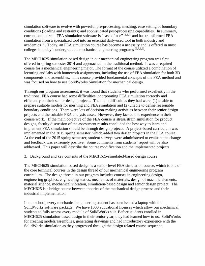
simulation software to evolve with powerful pre-processing, meshing, ease setting of boundary conditions (loading and restraints) and sophisticated post-processing capabilities. In summary, current commercial FEA simulation software is “ease of use” [1,6,7] and has transformed FEA simulation from a specialized tool into an essential daily-used tool in both industry and academics [6]. Today, an FEA simulation course has become a necessity and is offered in most colleges in today’s undergraduate mechanical engineering programs [6,7,8,9]. The MECH625-simulation-based design in our mechanical engineering program was first offered in spring semester 2014 and approached in the traditional method. It was a required course for a mechanical engineering major. The format of the course utilized a combination of lecturing and labs with homework assignments, including the use of FEA simulation for both 3D components and assemblies. This course provided fundamental concepts of the FEA method and was focused on how to use SolidWorks Simulation for mechanical design. Through our program assessment, it was found that students who performed excellently in the traditional FEA course had some difficulties incorporating FEA simulation correctly and efficiently on their senior design projects. The main difficulties they had were: (1) unable to prepare suitable models for meshing and FEA simulation and (2) unable to define reasonable boundary conditions. There were lots of decision-making activities between their senior design projects and the suitable FEA analysis cases. However, they lacked this experience in their course work. If the main objective of the FEA course is stress/strain simulation for product designs, faculty discussion of the assessment results concluded the best way to learn and implement FEA simulation should be through design projects. A project-based curriculum was implemented in the 2015 spring semester, which added two design projects in the FEA course. At the end of the 2015 spring semester, student surveys were administered to evaluate the change and feedback was extremely positive. Some comments from students’ report will be also addressed. This paper will describe the course modification and the implemented projects. 2. Background and key contents of the MECH625-simulated-based design course The MECH625-simulation-based design is a senior-level FEA simulation course, which is one of the core technical courses in the design thread of our mechanical engineering program curriculum. The design thread in our program includes courses in engineering design, engineering graphics, engineering statics, mechanics of materials, design of machine elements, material science, mechanical vibration, simulation-based design and senior design project. The MECH625 is a bridge course between theories of the mechanical design process and their industrial implementation. In our school, every mechanical engineering student has been issued a laptop with the SolidWorks software package. We have 1000 educational licenses which allow our mechanical students to fully access every module of SolidWorks suit. Before students enrolled in MECH625-simulation-based design in their senior year, they had learned how to use SolidWorks for creating models/assemblies, generating drawings and had introductory experience with the SolidWorks simulation as they progressed through the design related course sequence.

The format of the course MECH625 is a 2-4-4 course, which includes 2-hours lecturing with 4-hours lab for a total of 4 credits. In the modified MECH625, we used the first two and half weeks to discuss and to explore fundamental theory and concepts of FEA method. We discussed and demonstrated general procedures and purposes of each step of the FEA method if the FEA analysis was completed manually. We introduced the shape functions for 1D, 2D, and 3D objects and through the homework assignment, they derived solutions. Then, by using stepped bars with axial loadings, students were able to obtain element properties by using minimum potential energy principle, to assembly elements, to apply the boundary conditions and to solve for stress/strain. Through this two and half weeks, students began to appreciate the fundamental concepts of FEA method through lecturing, examples, and homework assignments. The modified MECH625 was mainly focused on using SolidWorks Simulation and implementing it for design projects. The main contents or skills in SolidWorks Simulation are generation / pre-processing of 3D models, assignment of materials, setting boundary conditions, creating appropriate meshing, defining contact conditions, post-processing, including applying the appropriate failure criterion, convergence iterations and interpretation of results [4]. The weekly plan of the modified MECH625 is provided in Table 1. Most homework assignments in the modified MECH625 were focused on developing some specific skills of FEA simulation. Successful completion of homework usually developed necessary skills for running well defined FEA simulation problems. The main objective of the modified MECH625 was to enable students to implement FEA simulation in design projects. To support this objective, two design projects were added in 2015 spring semester, which will be discussed in detail in the next section.
Table 1 weekly plan for the modified MECH625 Wk # Lectures and Labs Hw#
1 Lecture 1: Introduction to FEA method Lab 1: Part modeling and drawing
Hw#1 Hw#2
2 Lecture 2: Shape functions Lab 2: Shape functions and assembly & drawing Lecture 3: Element properties and 1D examples
Hw#3
3 Lab 3: Examples of bars under axial loading Lecture 4: Introduction to SolidWorks Simulation Lab 4: Get familiar with SolidWorks Simulation
Hw#4
Hw#5 4 Exam 1 (1/26/2015)
Lecture 5: Static analysis -1 (procedure, convergence, error in FEA, pre-process and meshing control) Lab 5: Pre-processing and shell element
Hw#6 5 Lecture 6: Static analysis -2 (loading & restraints, and H & P methods)
Lab 6: Boundary conditions: loading & restraints, and H& P methods for convergence Lecture 7 and lab 7: Static analysis-3 (symmetry and stress concentration) A minor project is released on 2/8/2015
Hw#7
Hw#8
6 Lecture 8: Static analysis -4 (contacts in assembly and post-processing) Lab 8: Contacting surfaces and post-processing Lab 9: Working on the minor project
Hw#9
7 Lecture 9: Static analysis -5 (type of connectors and bolt joint analysis) Lab10: Bolt joint analysis Lecture 10: Static analysis -6: interference fit analysis
Hw#10

8 Lab 11: Interference fit analysis Lab 12: Working on the minor project Exam 2 on 2/28/2015
Hw#11
9 Lecture 11: Fatigue analysis-1 (fatigue under constant amplitude cyclic loading) Lab 13: Fatigue analysis under a constant amplitude cyclic loading The due date of the minor project is 3/3/2015 Lecture 12 and lab 14: Fatigue analysis -2 (Miner rules and fatigue under several constant amplitude cyclic loadings) A major project is released
Hw#12
Hw#13
10 Lecture 13 and lab 15: Vibration and natural frequency Lab 16: Working on the major project Lecture 14: Thermal stress analysis-1 (steady thermal analysis)
Hw#14
11 Lecture 15: Thermal stress analysis -2 (transient thermal analysis) Lab 17: Thermal stress analysis Lab 18: Working on the major project
Hw#15
12 Lecture 16: Introduction to flow simulation Lab 19: External and internal flow simulation Lab 20: Working on the major project
Hw#16
13 Lecture 17: Reviews
Lab 21: Working on the major project Exam 3 (4/10/2015)
14 Lab 22 Working on major project The report and presentation of the major project are due on the scheduled final exam day.
3. Two design projects
Two design projects in the modified MECH625 were an individual minor project and a team-based major project. The minor project focused on developing several necessary skills for accurate component simulation. The team based major project was developed for students to explore the baseline of a flawed product and redesign it according to specified design specifications / constraints. Minor project: the FEA analysis of the member stiffness of the bolted joints The skills considered for the essential FEA simulation of components using SolidWorks Simulation were modeling, pre-processing, meshing, application of boundary conditions, convergence verification, and post-processing. At the end of week# 5, exercises for students to develop these skills through component simulations had been completed and the minor project was then assigned. The individual minor project was designed to focus on skills for running an FEA simulation in a project-based environment, in which students not only implemented necessary FEA simulation skills but also made some decisions. The ideal topic of a minor project should be the issues which cannot be solved by a simple closed-form theoretical calculation. But there are the empirical formulas / curves or tables for providing acceptable solutions. A variety of topics can be used for a minor project and effectively changed yearly if desired. For an example, the simulation of stress concentrations of components with various geometries and different loading is an excellent topic. Since stress concentrations cannot be obtained using a simple theoretical calculation, many handbooks and textbooks provide a set of curves.

The stiffness of a bolted joint is another ideal topic for a minor project. Bolted joints are one of the most common elements in construction and machine design. Fasteners in the joints capture and join other parts by securing components with mating screw threads. The member stiffness of the bolted joints is a key design parameter for the successful bolted joint design. In the simplified semi-empirical formula, the compressed volume of the member can be modeled as a frustum spreading from the bolt head or the nut to the midpoint of the grip as shown in Figure 1. Each frustum has a half-apex angle of α, which can be assumed to be 30 degrees [10]. The member stiffness of the bolted joints can be solved via FEA simulation as shown in Figure 1. Through design thread course coordination, we discussed the details of the joint stiffness calculation and associated empirical formula in the course “design of machine elements”. We decided to use the analysis of the member stiffness of the bolted joints using FEA simulation as the minor project for the modified MECH625. The main objectives of the minor project were: (1) integrate skills of FEA pre-processing and mesh refinement; (2) conduct simulation convergence analysis and (3) refine post-processing skills through the comparison of FEA simulation results with values from the empirical formula for the stiffness of members in a bolted joint. It was assumed that the members in the bolted joints were fabricated from the same material. Then the bolted-joint could be simplified as a block with a center-through hole as shown in Figure 2. Each student would run his or her study cases which are listed in Table 2.
Figure1 the model of compressed frustum and one image of an FEA simulation on a bolted joint
Figure 2 the simplified bolted joint model for FEA simulation

Table 2 the 21 different cases of FEA simulation on member stiffness Case # Bolt size Material of members Diameter-grip length ratio d/L
1~7 ¼”, 5/16”, 3/8”, 7/8”, 1”, 1 1/8”, 1 ¼”
Steel (AISI 1020)
d/L=0.05, 0.075, 0.1, 0.25, 0.375, 0.5, 0.75, 1.0, 1.25, 1.5, 1.75,2.0, 2.5
8~14 ¼”, 5/16”, 3/8”, 7/8”, 1”, 1 1/8”, 1 ¼”
Aluminum (6061-T6) d/L=0.05, 0.075, 0.1, 0.25, 0.375, 0.5, 0.75, 1.0, 1.25, 1.5, 1.75,2.0, 2.5
15~21 ¼”, 5/16”, 3/8”, 7/8”, 1”, 1 1/8”, 1 ¼”
Copper d/L=0.05, 0.075, 0.1, 0.25, 0.375, 0.5, 0.75, 1.0, 1.25, 1.5, 1.75,2.0, 2.5
The main activities of the minor project included: (1) create SolidWorks 3D models with inserting appropriate split lines; (2) conduct FEA simulation with convergence analysis; (3) use the deflection from FEA simulation to calculate the member stiffness. Notes: students needed to choose appropriate deflection for calculating the member stiffness. The type of deflections could be resultant defection or axial deflection. The values of the deflection could be the average values of the clamping surface or on the inner circle, or on the middle circle; (3) compare the member stiffness from the FEA simulation with that from the empirical formula; (4) use the Microsoft Excel to obtain an exponential curve-fit equation based on the FEA simulation results; and (5) write a technical report. Through this minor project, students harnessed their FEA simulation skills and also greatly increased their interests on FEA simulation. Students submitted technical reports upon successfully completing the minor project. Major project: strength analysis of an engine hoist At the end of week# 9, the major design project was released after we completed the use of FEA simulation on assemblies. The key topics for assembly analysis included analyzing contact between components, simplified mathematical representations of connectors such as bolts, pins and interference fits. Many of these topics were implemented in the major project. Creation of an appropriate design project for an undergraduate FEA simulation course was a difficult task. The following three main factors were considered during the development. First, the design project should have simple design functions and without dynamic loading. It was considered critical that students could easily understand the operation or performance of the main components and sub-assemblies relative to the design constraints. For a project with a small motion speed, static analysis was only required. Second, the design project should be meaningful or a real product with design flaws purposely included. A real product could greatly increase students’ interests in conducting FEA simulation and redesigning it because the product would require real design constraints / specifications. The experience they gained through this project could be an industrial hands-on real FEA simulation experience. Third, the design project should be manageable because it was still a course design project. After careful consideration and collaboration among faculty, strength analysis of an engine hoist was chosen as the major project for the modified MECH625. An engine hoist or engine crane in Figure 3 is a common repair tool used in vehicle repair shops to remove or install engines in the small and crowded vehicle engine compartments. It is also used in small workshops or homes to lift and move heavy objects. Engine hoists can be found in

both hardware and automotive parts stores. Some students even indicated they operated or owned such a product. The design specifications for the engine hoist in the major project included a minimum factor of safety of 1.5 and maximum allowable deflection 0.375” at the end of the boom. Since the provided engine hoist did not satisfy the design specifications, it needed to be redesigned. The engine hoist shown in Figure 3 consists of four sub-assemblies: (1) the adjustable boom-assembly with three rated lift weight capacities of 0.5T, 1T and 2T achieved by three different locking pin positions; (2) the manual hydraulic pump for raising or lowering the boom-assembly; (3) the post-assembly for supporting the pivot pins of the boom assembly; and (4) the base-frame assembly. The complete 3D models of the engine hoist for the major project were provided to the students. During the student redesign efforts, they needed to create new part models and assemblies as necessary to comply with given specifications. The major project was a team-based project with 2~4 team members. After the major project was released, one hour lecture time per week was used to discuss the major project and to answer questions. The lecturing was not to show how to run the FEA simulation of the major project, but explained some possible directions or approaches since a variety of potential approaches existed. One two-hour lab per week was devoted to working on the major project in a classroom while the instructor was available to provide guidance. Each design team was also asked to spend at least an additional two hours outside of the classroom working on the major project.
Figure 3 the isometric view of an engine hoist
The main activities conducted during the execution of the major design project were: (1) use engineering statics to determine maximum reaction forces on pivot pins for strength analysis on them; (2) determine the worst loading scenario of the engine hoist components at three different rated lift weights for FEA simulation; (3) pre-process to exclude parts or sub-assemblies from the FEA simulation if they were obviously safe; (4) run FEA simulation, which could be whole assembly or individual sub-assembly, such as the boom-assembly and the post-assembly; (5) complete the baseline analysis to determine the factor of safety and maximum deflection of each

key component; (6) redesign the engine hoist and re-run FEA simulations on the new version of the engine hoist until it satisfies the design specifications; (7) write a technical report on the major project; and (8) conduct the presentation of the major project. Because the project was based on a real product, the design teams embraced the needs to cooperate closely with each other, to implement / integrate skills and knowledge they had acquired so far from every one of the program design thread courses. It was an intense and tough simulated workplace immersion requiring many critical decision-making activities. Even though some strength analysis could be completed with simple theoretical hand calculations such as the pivot pins, or some components could be excluded from the FEA simulations, such as the handle of the hydraulic pump and the base-frame assembly, it provided a real world feeling for the students. For the major project, the FEA simulation could be on each sub-assembly such as the boom-assembly and the post-assembly or the FEA simulation and could be on whole engine hoist excluding the base-frame assembly. However, since a number of the total elements for SolidWorks Simulation is controlled by the Laptop resource such as available computer memory, they needed to use big element size for the analysis on the whole engine hoist or could have fine element size for the analysis on each individual sub-assembly. Students needed to specify loading and restraints if the FEA simulation was conducted on a sub-assembly, which was the preferred method to maximize student learning. Students needed to properly implement mesh refinements, otherwise, the meshing of the engine hoist subassemblies could result in “failed” mesh generation. With the helps from instructors during the dedicated lab sessions, design teams maintained high spirits because the experience gained was directly applicable for their coming senior capstone design, it was a real product design, and experience would be directly applicable to their future career. Design teams presented PowerPoint presentations and submitted technical reports of the major project upon completing the project. 4. Comments on students’ feedback and students survey analysis Comments on students’ feedback Students needed to submit technical reports for the minor project and the major project. They needed to present PowerPoint presentation on the major project. The followings were some comments and discussions on the reports.
• For the minor project, they mentioned in their reports that they learned more through the minor project than homework assignment because they used the combination of every skill learned and needed to conduct their decision-making activities in order to complete the project. During the decision-making process, they might need to make some changes and rerun the simulation or the calculation, which were a burden to them. But they said that they were happy with the changes because they knew why they needed to make such changes. Some students proudly said that this was the first time they built a formula through FEA simulation, which might be used for their mechanical design.
• For the major project, they mentioned in their reports that they learned most through the major design project in the course. They needed to implement every FEA simulation skill in the project. The most challenges in the major project they said were a lot of

decision-making activities such as choice of whole machine or individual assemble, exclusion of some parts for the FEA simulation, element size, and definitions of the boundary conditions. But they also mentioned they actually learned more through these decision-making activities in the environment of a design project.
• Every student successfully completed the minor project and every design team successfully redesigned the engine hoist per the design specifications. From the project reports and per some conversations with students, students indicated that they had real hands-on experience of running FEA simulation on design projects and believed that they knew how to implement FEA simulation for design projects. These indicated the main objective for the modified MECH625 course had been successfully satisfied.
Students survey analysis At the end of spring semester 2015, an extensive student survey was conducted. Student feedback is shown in Table 3. According to Table 3:
• 100% of students agreed that the design projects were a must for a simulation-based design course;
• 100% of students agreed that design projects strongly helped them to develop a better understanding of FEA simulation;
• 95% of students agreed that design project strongly improved their FEA skills; • 84% of students agreed that the design projects strongly improved their understanding on
engineering statics; • 90% of students agreed that the design projects strongly improved their understanding of
the mechanical design and the design process; • 95% of students agreed that design projects strongly improve their skills for CAD
modeling and drawing; and • 90% of students agreed that major design project strongly improved their teamwork skill.
In a summary, the course was successfully implemented and student feedback about the design projects in the course was extremely positive.
Table 3 student survey results Choice Strongly agree Agree No opinion Disagree Strongly disagree Question #1: Design projects are a must for MECH625-simulation-based design class results 8 11 0 0 0 Percentage 42% 58% 0% 0% 0% Question #2: Design projects help me to have better undersigning of FEA simulation results 10 9 0 0 0 Percentage 53% 47% 0% 0% 0% Question #3: Design projects strongly improve my FEA analysis skills. results 10 8 0 1 0 Percentage 53% 42% 0% 5% 0% Question #4: Design projects strongly improve my understanding on Engineering Statics results 5 11 3 0 0 Percentage 26% 58% 16% 0% 0% Question #5: Design projects strongly improve my understanding of mechanical design and design process results 10 7 2 0 0 Percentage 53% 37% 10% 0% 0%

Question #6: Design projects strongly improve my skills for CAD modeling and drawing results 6 12 0 1 0 Percentage 32% 63% 0% 5% 0% Question #7: Major design project strongly improves my teamwork skill results 7 10 2 0 0 Percentage 37% 53% 10% 0% 0%
The followings were some student comments obtained both directly from the student survey and indirectly through conversations between instructors and students:
• “Design projects make learning course material a challenge and this ultimately makes students have a better understanding of the materials presented.”
• “It was important to see the application of what we were learning through the design projects.”
• “Design projects are important because they allow the students to apply what they learn to a real application.”
• “The projects give more of a real-world application to preforming the simulation. They also provide more of a thorough examination of the results and failures. I learn a lot from projects rather than just lectures.”
• “Design projects help reinforce skills learned in class. They allow for the implementation of theory into real-world practice.”
• “Design projects reinforce the material taught in class as well as provided real-life scenarios.”
• “The major design project is a good way to wrap up the course in that it includes most of the skills taught in the course.”; and
• “I though the major project was setup very well and helped learned the practice of the theoretical information learned.”
5. Discussions and conclusions
FEA simulation is one of the essential daily-used tools for engineers in the industry today and has been widely used in product designs because theoretical analysis on real products with complicated geometries and boundary conditions are extremely difficult. Mechanical engineering students should have a chance to explore and to learn this tool in their mechanical engineering program curriculum. Students could learn lots of FEA simulation skills through homework assignment in the traditional lecturing and homework approach. But since homework assignment had normally closed definitions about the problems, there were few decision-making activities for students. We believed that this might be the reason that some students did excellently in a traditional course, but had some difficulties to start FEA simulation for their senior design projects. In the modified MECH625, two design projected were conducted. These two design projects required lots of decision-making activities in order to successfully complete design projects. Students indicated that the decision-making activities during the projects significantly increased their workloads. However, they said that they learned more through the decision-making activities. Through the design projects with the help of instructors, students learned how and why to conduct the decision-making activities for implementing FEA simulation on the projects.

Since the projects were manageable and meaningful, they cumulated real hands-on experiences of FEA simulations on design projects. Our experience through the modified MECH625 course strongly indicated that undergraduate students could successfully learn how to properly implement FEA simulation to conduct effective and accurate product designs. The combination of lecturing, lab practice on FEA simulation, homework assignment, and design projects had been shown to be a successful approach for teaching an FEA simulation course for undergraduate students. After students had some fundamental FEA simulation skills on FEA software, conducting design projects could be one of the best ways for students to learn FEA simulation. 6. References [1] R.E. Link, and S.M. Miner, “A Project Based Introduction To The Finite Element Method”, ASEE 2000 Annual
Conference, June 18-21, St. Louis, Missouri. [2] J. Rencis, and etc., “Finite Element Learning Modules For Undergraduate Engineering Topics Using
Commercial Software”, ASEE 2008 Annual Conference, June 22-25, Pittsburgh, Pennsylvania. [3] W.O. Jolley, J.J. Rencis, and H.T. Grandin, Jr., “ A Module for Teaching Fundamentals of Finite Element
Theory and Practice Using Elementary Mechanics of Materials”, ASEE 2003 Annual Conference, June 22-25, Nashville, Tennessee.
[4] John R. Steffen, “Analysis of Machine Elements Using SolidWroks Simulation 2014”, SDC Publications, 2014 [5] X. Le, X., A.W. Duva, and M. Jackson, “The Balance of Theory, Simulation, and Projects for Mechanical
Component Design Course”, ASEE 2014 Annual Conference, June 15-18, Indianapolis, Indiana. [6] J. Zecher, “Teaching Finite Element Analysis in an MET Program”, ASEE 2002 Annual Conference, June 16-
19, Montreal, Canada. [7] W. Howard, T.J. Labus, and V.C. Prantil, “Combining Computer Analysis And Physical Testing In A Finite
Element Analysis Course”, ASEE 2004 Annual Conference, June 20-23, Salt Lake City, Utah. [8] Y. Dong, P. Zang, and A. Mazzei, “Development Of A Cae Course Project Focusing On Project Data
Management And Virtual Prototyping Through Fea Of Windshield Wiper System Design”, ASEE 2008 Conference, June 22-25, Pittsburgh, Pennsylvania.
[9] P. Chaphalkar, and D. Blekhman, “Introducing Finite Element Analysis In The First Course Of Statics And Solid Mechanics” ASEE 2007 Annual Conference, June 24-27, Honolulu, Hawaii.
[10] R.G. Budynas and J.K. Nisbett, “Shigley’s Mechanical Engineering Design”, 10th Edition, McGraw Hill 2015.