
The Design of Steel Frames.pdf
35
Bukrr, on Design of Steel Frames 397 THE DESIGN OF STEEL FRAMES * By Professor 3. F. Baker, O.B.E., M.A., ScD, M.I.C.E., M.1.Struct.E. SYNOPSIS Between 1929 and 1936 a comprehensive investigation of the behaviour of steel structures was made for the Steel Structures Research (2ommittee.a A summary of the work is given together with a short account of the Design Recommendations made. This design method was not popular and the conclusion was reached that theeIastic behaviour of a redundant structureis too complicated to form the basis of a simpler rational method. An investigation of the behaviour of structures in the plastic range up to collapse was therefore begun 7-28 in the hope that a more acceptable rational method of design would result. The simple plastic theory of bending is discussed shortly. The modes of collapse of rectangular portals are examined and a direct method of plastic design is given in some detail. Pitched roof portals are then dealt with and it is shown that consideration of conditions at collapse leads to a rational design method which is simpler and more economical than the orthodox elastic method. 1. INTRODUCTION Though this country may not be the greatest user of structural steel nowhere, in the past twenty years, has greater attention been paid to the study of the behaviour of steel structures and to the derivation of rational methods of design. While advances in methods of stress analysis can be made by indi- vidual investigators, the most striking in modern times being that due to Hardy Cross,l the comprehensive study of the behaviour ocsuch complex structures as steel building frames is beyond the capacity of any individual- or firm since experiments have to be made on more or less full scale structures. It is not surprising, therefore, that little information of any value existed as to the real behaviour of these structures before 1929, when the British Steelwork Association co-operated with the Department of Scientific and IndustrialResearch and devoted money and energy to a study of fundamental behaviour, techniques and practices in steelwork design. The SteelStructures ResearchCommittee was set up and for seven years actively prosecuted research and eventually produced recommendations for a design method.2 No account of the Committee’s work seems to have been given to the Institution and as it must be taken * Papr to be read before the Institution of Structural Engineers at 11, Upper Belgrave Street, Z,ondon, S. W.1, .m Thursday,27th October, 1949, at 6 p.m.
-
Upload
jeffrey-munoz -
Category
Documents
-
view
17 -
download
2
Transcript of The Design of Steel Frames.pdf

B u k r r , on D e s i g n of Steel Frames 397
THE DESIGN OF STEEL FRAMES * By Professor 3. F. Baker, O.B.E., M.A., S c D , M.I.C.E.,
M.1.Struct.E.
SYNOPSIS
Between 1929 and 1936 a comprehensive investigation of the behaviour of steel structures was made for the Steel Structures Research (2ommittee.a A summary of the work is given together with a short account of the Design Recommendations made. This design method was not popular and the conclusion was reached that the eIastic behaviour of a redundant structure is too complicated to form the basis of a simpler rational method. An investigation of the behaviour of structures in the plastic range up to collapse was therefore begun 7-28 in the hope that a more acceptable rational method of design would result.
The simple plastic theory of bending is discussed shortly. The modes of collapse of rectangular portals are examined and a direct method of plastic design is given in some detail. Pitched roof portals are then dealt with and it is shown that consideration of conditions at collapse leads to a rational design method which is simpler and more economical than the orthodox elastic method.
1. INTRODUCTION
Though this country may not be the greatest user of structural steel nowhere, in the past twenty years, has greater attention been paid to the study of the behaviour of steel structures and to the derivation of rational methods of design.
While advances in methods of stress analysis can be made by indi- vidual investigators, the most striking in modern times being that due to Hardy Cross,l the comprehensive study of the behaviour ocsuch complex structures as steel building frames is beyond the capacity of any individual- or firm since experiments have to be made on more or less full scale structures. I t is not surprising, therefore, that little information of any value existed as to the real behaviour of these structures before 1929, when the British Steelwork Association co-operated with the Department of Scientific and Industrial Research and devoted money and energy to a study of fundamental behaviour, techniques and practices in steelwork design. The Steel Structures Research Committee was set up and for seven years actively prosecuted research and eventually produced recommendations for a design method.2 No account of the Committee’s work seems to have been given to the Institution and as it must be taken
* Papr to be read before the Institution of Structural Engineers at 11, Upper Belgrave Street, Z,ondon, S. W.1, .m Thursday, 27th October, 1949, at 6 p.m.

398 The Structural Engineer, October , 1949
into account in assessing later developments it will not be out of place to refer to it briefly here. I t is worth noting also that the method is of more practical interest now to structural designers than it was when first published, since the 1948 edition of British Standard 449, the Use of Structural Steel in Building, lays it down in Section 29(b) that for “ semi-rigid ” structures the designs shall be made in complete conformity with the “ Recommendations for Design ” in the Final Report of the Steel Structures Research Committee 1936, except that all connections of beams to stanchions and beams to beams or girders in which restraining moments are taken, shall be riveted.
2. SUMMARY OF S.S.R.C. INVESTIGATIONS The Steel Structures Research Committee lost no time in embarking
on full scale tests of structures and details so that they would have a sound knowledge of the real behaviour of steel frames on which to base recommendations for design.
The first structure tested was a specially built experimental frame made up of 8 in. x 4 in. x 18 lb. steel joists so arranged that experiments could be carried out on a large variety of one and two bay three storey frames with various types of beam to stanchion connexions.
The early tests showed that in all these frames, though the connexions were relatively flexible, consisting as they did of 34 in. X 3 in. X & in. angle, 4 in. long, secured with 3. in. diameter bolts, the distribution of stress in the members was exactly of the same form as it would have been in a rigidly jointed structure. The restraining moments a t the ends of the beams and the bending moments in the stanchions were certainly less than they would have been in a rigidly jointed frame but they were surprisingly large. For instance, where a beam framed into the web of a stanchion, the ‘‘ equivalent eccentricity ” (that is to say the distance from the axis of the stanchion at which the reaction arising from a similarly loaded simply supported beam would have had to act to produce the observed bending moments in the stanchion) \vas of the order of 9 .5 inches, being rather more than half what it would have been in a rigidly jointed frame.
The next step was to investigate the behaviour of actual buildings. The first to be tested was the new Geological Museum, South Kensington, but more complete tests with improved instruments were made on the Cumberland Hotel, the Euston office block and the Latymer Court residential flats. The structural steel industry owes a great debt to the architects and engineers concerned who made it possible, with no little inconvenience to themselves, for experiments to be carried out on these structures. A wealth of information is contained in the full account of the work published in the Committee’s Final Report; it is only possible here to mention a few outstanding points.
Again it was found that the stress distribution in the steelwork was very similar in form to that which would have been found in a rigidly

R a k e r , on D e s i g n of Steel Frames 399
jointed structure. The Gagnitudes of the bending moments induced can be gauged from the fact that the equivalent eccentricity of a connexion lay between 30 0 and 44 6 inches for the bare frame of the Hotel Building and between 16 0 and 34 3 inches for the Office Building. These restraining moments, while reducing the maximum stresses in the beams by from 17 to 25 per cent of those which would be found in similarly loaded simply supported beams, were responsible for large bending stresses in the stanchions, in some cases as much as 9 times those which would be estimated by the orthodox design method. Another illustration of how far real conditions depart from those assumed in orthodox stress calculations was found when strain readings were taken 12 inches above the foot of a stanchion of a bare frame resting on a steel slab. I t was found that the stress a t one corner of a flange was 17 times as great as that at any other corner. ' The load applied to this stanchion by the placing of floors must have been sufficient to produce local yielding in the foot of the stanchion since, when the test was repeated after the floors were in position, the distribution of the additional stress across the section due to the test load was quite normal.
A knowledge of the effect of clothing a building structure is essential. The placing of floors and the introduction of walls influence the stress distribution in complex ways and it is not easy to study them all separately. The addition of floors decreased the bending stresses induced in the stanchions of the Hotel Building by from 37 6 to 21 - 1 per cent in some cases but increased them in others. In the Office Building, where the beam to stanchion connexions were relatively more flexible and so more influenced by the concrete casing, the presence of floors increased the stanchion stresses by as much as 66 5 per cent. Again when stanchion casing and walls were added a slight decrease in stress was found in the stanchions of the Hotel Building but in the Office Building an appreciable increase was found, for instance in one stanchion length of this fully clothed building the bending stress was 2 89 times that which would have been set up in the bare frame.
The maximum stress in a beam is clearly very much influenced by the restraint supplied at its ends by the connexions. Considerable information of the behaviour of connexions was obtained from the full scale tests but in addition large scale laboratory tests were made on a great variety of beam to stanchion connexions and their behaviour was thoroughly explored.
In deriving a rational method of designing so complex a structure as a building frame, simplification. can only be obtained by considering worst conditions. I t was clear from the tests that, for beams supported by relatively flexible semi-rigid connexions, a safe approach would be to assume the connexions to be unaffected by the placing of floors or the casing of stanchions and to assume a reasonable lower limit of two- thirds that of the beam for the stiffness of the stanchion into which it framed. In this way it was possible, from the results of the laboratory

,400 T h e Structural Engineer, October, 1949
tests, to prepare curves which showed directl? the restraining moment which any standard connexion could be relied upon to supply. Using these curves, economical beams could be designed almost as simply as by the orthodox “ pin-jointed ” method, without a prior knowledge of any other member in the structure.
Stanchion design, however, presented greater difficulties. I t was clear from the tests on actual buildings that the effect of casing on the behaviour of connexions could not be neglected where stanchion stresses were concerned-that in fact, safety could only be ensured by assuming that the connexions were made perfectly rigid by the casing. This being so, the most critical stress condition in a stanchion length would not be developed when all floors were loaded, as is assumed in the orthodox design method (Fig. l (a)) , when the axial stress has its greatest value but the bending stresses (shown over the length AB) are relatively small. In a frame with rigid joints the bending stresses will be very greatly increased if load is removed from a floor below to one side of the stanchion (Fig. 1 (b)) and still further increased if load is removed from other floors (Fig. 1 (c)) . I t will be seen from the shape of the bending stress diagram in this last case that the stanchion is bent in double or S-curvature so that the greatest stress will be found at or near one end of the member. If other combinations of floors are loaded (Fig. l(d)) the stanchion length can be bent in single curvature, the maximum bending stress occurring in the neighbourhood of the centre of length, so that “ strut action ” is more apparent. From this short discussion it will be seen that the usual “ effective length ” method of stanchion design has no rational basis and that any really satisfactory method of design must automatically take account of the most rigorous loading conditions on the structure.
I t was not found easy to produce a simple but general method of selecting the most rigorous loading condition for any stanchion length because of the possibility of it occurring under either double or single curvature conditions. I t was however possible to produce a workable method by keeping these conditions separate. Lengthy analysis showed
FIG. 1

t luker , on Design of Steel Frames 401
that the greatest bending moment which could be developed under either condition could be tabulated in terms of M F ~ and M F ~ , the "fixed-end" moments at the ends of the beams framing into the stanchion length, and depending on the stiffnesses (moment of interia divided by length, denoted by XSR'and KBL) of these members and of the stanchion lengths above and below ( X U and XL) . The form of the table for live loads is shown as Table 1.
TABLE 1
TorAL EENDINC MOMENT DUE TO LIVE LOAD
Intermediate I Topmost Length l I-ength
.- Double F',, Sin.gle
Curvature
1 *20hl,,
O*ti3MF, 0-90MF,
- 0 * 0 7 M F 2 +0.27MF, 0.86hlF,
+0.15MF2 -0*13hIF,
l
. - l p-
Single Curvature
0*87hZ,, -0*03MF,
0. B3 M,, - 0.08 M,,
I t was also possible to produce familie? of curves showing the permiss- ible end bending stressfA which could be tolerated with any axial stress, p , and slenderness ratio, -. These curves are shown for the single curvature
condition in Fig. 2 and for the double curvature condition in Fig. 3. They were drawn, as were those for the restraining moments on beams mentioned earlier, so that providing for a load factor of 2 the total stress in the 'member would not exceed the yield stress of the material (assumed to be 18 tons per square inch).
The procedure should be clear to a structural designer. U'hen considering any stanchion length XBR, X B L and X U will be known since the beams and stanchion length above will have already been designed. A stanchion section is selected giving X L and, for the condition of single cun'ature bending, the bending moment is read from the appropriate column of Table 1. The bending stress f~ is calculated from this and, taking as the value ofp the load per unit area when all beams above the stanchion length are loaded, the adequacy of the stanchion section selected is checked from the appropriate curve of Fig. 2. The procedure is repeated for double curvature bending, reading the bending moment from the appropriate column of Table 1 and checking the adequacy of the section from Fig. 3.
A number of engineers were good enough to give the method described
L r

402 T h e Structural Engineer, October, 1949
p : TONS PER SQINCH.
above a trial in their offices. They were, unfortunately, unanimously of the opinion that while designers had no difficulty in applying the method, the time taken in proportioning a stanchion was prohibitive, the reason being, of course, that two critical loading conditions had to be considered separately for each stanchion length. To produce a method acceptable to the designer, further simplification was essential. This was done, without undermining the principle of the original method, by producing one set of composite strut curves giving the permissible end bending stress which would ensure safety whether bending was in ‘‘ single ” or ‘‘ double ” curvature, by amending the table of end moments (Table 1) so that only one condition had to he considered and expressing the moments in terms of M F ~ the greatest fixed end moment. This final method is that set out in the “ Recommendations for Design ” published at the end of the Final Report S.S.R.C. and described, together with a summary of all the Committee’s work, in a paper published by the Institution of Civil engineer^.^
3. THE INVESTIGATION OF PLASTIC BEHAVIOUR
In spite of the simplification described above, the Steel Structures Research Committee’s method, though successful from the scientific point of view, could hardly be described as popular. This was due
p .TONS PER SQ. INCH.
FIG. 3 . Permissible end bending stress with “ double curvature.”

Ba.ker, o n Design of Stve l Frames 403
partly to its relative complexity and partly to the fact that it offered little economy over the orthodox method. Every simplifying step made in a rational method means loss of economy. Nevertheless, due to ad- vances recently made in the knowledge of the behaviour of continuous stanchions, something might now be done to improve the efficiency of the method by reducing the load factor used, but nothing could be done to make it less complex without sacrificing its rational basis. When it is remembered that this rational method dealt only with the most straightforward multi-storey frames, that such complications as set back columns were not covered and that the single storey factory building and such special types as theatres and auditoria were not included, it will be realised that the position was not cheering. In fact the unfor- gettable lesson learnt by at least one investigator is that the elastic behaviour of a redundant structure is too complicated to form the basis of a simple and acceptable but still rational design method.
I t would, however, be a depressing prospect for the structural engineering profession if the only tool ever to be available to the designer were one which had little rational basis and so could not be refined further and applied effectively to such cases as the modern rigidly jointed welded frame. If behaviour in the elastic range is too complex might not a consideration of the plastic behaviour of a ductile structure lead to happier results ? In one section of the orthodox method of designing steel frames, that relating to stanchions, collapse of the member is the basis; might not the truly rational approach to design be, therefore, through the conditions at collapse of the structure as a whole ?
Thirteen years ago, when the Steel Structures Research Committee stopped its work, little was known of the modes of collapse of redundant structures. Experimental work was therefore embarked upon in the Civil Engineering Department, University of Bristol. Up to the begin- ning of the war help was provided from the modest resources of the Welding Research Council of the Institute of Welding. Work stopped in September 1939, but the experiments had been carried far enough to provide a useful basis for the design of certain unusual wartime struc- tures some of which were described to the Institution in a lecture, entitled c c Principles of Design of Protective Structures,’’ on the 10th June, 1943.
In 1944, fundamental work was started once more and has continued ever since, in the Engineering Laboratory, University of Cambridge, where it has been given considerable support by the British Welding Research Association and by a special grant from the Department of Scientific and Industrial Research.
Many full reports, dealing mainly with the experimental work have been p~b l i shed ,~ -~* or are in the press and a review of the investigation has recently been made a~ai lab le .~ I t is not proposed, therefore, to detail here the experimental basis of the work but to confine attention to such

4 04 T h e Structural Engineer, October, 1949
of the analytical work and its application to design which will be of particular interest to the structural engineer. The designer can rest assured that nothing has been assumed in the analysis which has not been satisfactorily substantiated by many tests on small and full scale structures.
(a) T h Simple Plastic Theory o f Bendiq
The simple plastic theory of bending for mild steel is nothing more than an extension of the well known elastic theory, according to which the longitudinal stress distribution across any section of the beam acted upon by a pure bending moment takes the form shown in Fig. 4(a). This theory holds for all bending moments less than the yield moment t) l j ,
under which the yield stress of the material is reached in the extreme fibres. The beam is capable of sustaining a bending moment greater than m,, but in order to deduce the corresponding stress distribution, it is necessary to consider the nature of the stress-strain relationship beyocd the yield point. This depends on the composition and history of the steel but for structural mild steel in general, the curve shown in Fig. 5 is a sufficiently close approximation. After yield a t B, there is a range BC,' of pure plastic deformation with .no increase of stress, until strain harden- ing occurs at C at a strain of from 8 to 20 times the strain a t yield. The pure plastic range IIC is sufficient to enable considerable deformations to take place before strain hardening has any significant effect. I t is therefore reasonable to assume that after the yield stress has been reached in any fibre of' a beam under increasing bending moment, the stress in that fibre will remain constant. After this process has been carried some depth into the beam the stress distribution will therefore be as shown in Fig. 4(b), which corresponds to a moment of resistance somewhat greater than the yield moment my. The maximum moment of resistance is obtained when the whole section has been strained beyond the yield point (Fig. 4(c)), its value then being referred to as the full plastic moment, Inp.
A quantity of immediate importance when dealing with the plastic
-0. 4. Wa. 6.

B a k c r , on Design of S t e e l Prumcs SOS
theory of bending is the ratio of mp to m,. For a beam bent about an axis of symmetry, m,, has the value
m3, = Zf,, .......................... (1)
where 2 is the elastic modulus of the section. I t will be apparent from Fig. 4(c) that the value of m p can be obtained by multiplying the first moment of area of the section about the axis of bending .by the yield stressf,,. Hence, denoting the first moment of area by-?
“ p = sf.. / . .......................... (2) and therefore
2bda4 3
For a rectangular section of depth 2d and width 6,Z = - and
S = bd2, so that
S - z= 1 . 5 . . . . . . . . . . . . . . . . . . . . . . . . . . (4)
S z The value of -depends entirely upon the geometry of the cross-section,
S and may therefore be referred to as the “shape factor.” The value of - z for most standard rolled I-beams (R.S.4.), bent about the major axis, is 1 15 approximately.
(11) Sinzpb Supported and Fixed Ended Beams . The stress distribution in Fig. 4(c) corresponds to theoretically
infinite curryature, and therefore when the full plastic moment has been reached at any section of a simply supported beam, the deflections become indefinitely large and collapse is said to occur, though it is well to remember that if the load uere reduced a little it could be supported quite safely. If, therefore, the total load on such a beam is gradually increased, the distribution remaining the same, the ratio of the load at collapse to the load when yield begins is equal to the shape Fixtor for the beam. If, holyever, the ends of the beam are fixed in direction, collapse cannot occur until the full plastic moment has been reached at three sections. Consider, for example, a fixed-ended beam subjected to a uniformly distributed load (Fig. 6(a)). In the elastic range the bending moments at the ends will be twice that at the centre so that yielding will
.begin at the ends of the beam under the bending moment distribution shown in Fig. 6(b). As the load is increased zones of yielded material will develop at the ends of the beam until full plasticity has been reached a t the end sections. As the load is further increased, the end bending

406 The Structural Engineer, Ocf ober, 1949
I
moments will remain constant at the full plastic value mp, and at a certain stage yield will occur at the centre (see Fig. G(c)). At the same time relative rota- tions will take place between the ends of the beam and the rigid supports. Collapse will finally occur when the central section also becomes fully plastic, when the bending moment diagram and the approximate extent of the zones will be as shown in Fig. 6(d).
Now let W,, denote the load at which yield stress is first reached a t the ends (Fig. 6(b)), and W, the collapse load (Fig. 6(d)). For the former con- di tion,
while for the latter condition, since the sum of the end and central moments must equal the central bending moment for the same load carried on a simply supported beam,
Hence W C 4 " p - 4 S -- - 3 2- . . . . . . . . . . . . . . . . (7) W,, 3 m,,
The effect of fixing the ends of the beams is therefore to increase the ratio of the load a t collapse to the load at yield. This shows that elastic design methods do not always take advantage of the full additional strength obtained from end fixity. I t will also be seen that if there are two beams in a structure, one simply supported and one encastrk, both designed by the usual working stress method for the same design load, then the latter will be capable of carrying one-third more load before collapse than the former. For static loads when strength is the design criterion, can this be defended ? If the load factor enjoyed by the simply supported beam is adequate, why should it not be used for the encastrt5 beam with a resultant economy of material ? This is the whole basis of the plastic method of design for redundant structures.

B a l x r , on Design of Stee l Frames 407
I t has been assumed above that the ends of the beam are completely fixed in direction. This is hardly a practical condition, since although the end connexions may be capable of withstanding the full plastic moment of resistance of the beam, they cannot completely fix its ends against rotation. Whereas such flexibility will modify the load at yield ( Wy) and the stages leading up to collapse, the final collapse load is unaffected. In elastic design, stress distributions are dependent upon the flexural stiffness ratios of the members, a fact which makes direct design difficult, whereas the collapse loads of members subjected to trans- verse loading may be estimated without reference to such ratios. Collapse load is also independent of any relative sinking of supports, so the im- portant conclusion is reached that the inevitable practical imperfections in a structure, lack of complete rigidity ofjoints and the sinking of supports which completely invalidate the usual elastic stress determination, have no effect on the plastic method.
(c) The Effect of Axial Loads
If a member is subjected to a bending moment combined with an axial load per unit area p and the yield stress is not exceeded, the resultant stress distribution (Fig. 7 (c)) may be derived by superimposing upon the mean axial stress (Fig. 7(a)) the stress distribution corresponding to the bending moment acting alone (Fig. 7(b)). The resultant effect is to move the neutral axis N A away from the geometric centre line. In the plastic range the superposition of separate stress distributions is impossible, but the resultant effect of an axial load is again to move the neutral axis. When fully plastic, a member of I-section for instance (Fig. S(a)) would have a stress distribution of the type shown in Fig. 8(b), the effect of the axial load being, to move the neutral axis from XX to AA. Taking moments about the axis X X , it is found that the moment of resistance at full plasticity is reduced by the axial load. For a 15 in. X 6 in. X 45 lb. I-beam bent about the major axis, the relationship between the full plastic moment (mp) and the mean axial stress is shown by the upper curve in Fig. 9 for an assumed yield stress of 16 tons/in.2 I t is interesting
i p t - l
(b) FIG. ?.

408 The Structural Engineer , Oc tober , 1949
and important to see that for small mean axial stresses up to about 4 tons/in.2, the reduction in m p is surprisingly snlall. The
C locrer straight line gives the bending moment -x m3, at which yield stress is first reached in * the most .highly stressed fibres of the
member. I Yfl& It
(a> b) (d) The Ultimate Carrying Capacity of a Portal IiYarne
FIG. 8 .
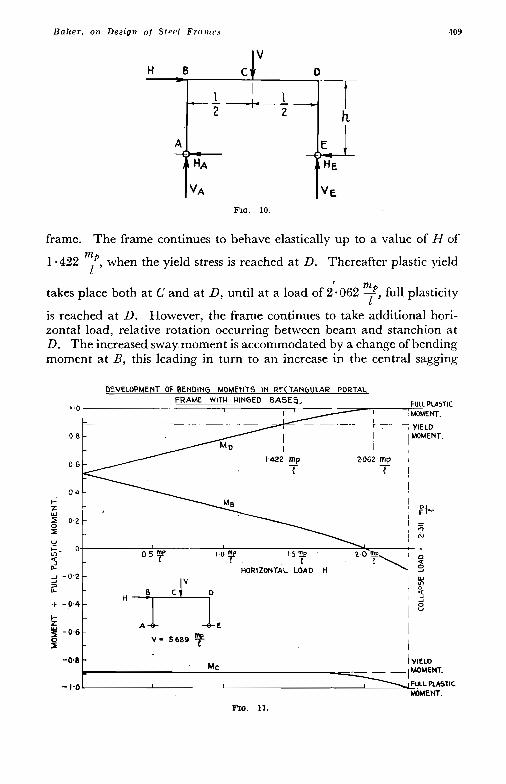
The simple plastic theory may readily be applied to a simple portal frame such as that shown in Fig. 10. As an example, consider a frame hinged to the foundations at A and E, the span I being twice the height h. Let the frame be of the same uniform I-section throughout having a " shape factor "
(:) of 1 125. XOM. let a vertical load V be applied to the centre
of the beam until the . maximum bending moment in the frame (which occurs directly under the load) reaches the value nz,,. I t is readily shown that
m m l l
F7 = 6 . 4 2 =: 5.689 .-p
Now let a concentrated horizontal load H, acting from left to right, be applied at beam level until complete collapse occurs. The variations of the bending moments ;\{B, M C and.Mo a t B, C and D respectively as H is increased are shown graphically in Fig. 11. Bending moments are accounted positive \vhen they produce tension on the outside of the
0 2 4 6 8 IO 12 14 16 AXIAL STRESS (TONS/ INCH^)
FIG 9.
109
frame. The frame continues to behave elastically up to a value of H of
1.422 3, when the yield stress is reached at D. Thereafter plastic yield
takes place both at C and at D, until at a load of 2 a062 -*, full plasticity
is reached at D. However, the frame continues to take additional hori- zontal load, relative rotation occurring between beam and stanchion at D. The increased sway moment is accommodated by a change of bending moment at B, this leading in turn to an increase in the central sagging
l ’ m
l
S” 0
-0.8 - I YIELO
MOMENT.
FIG. 11.

'l 10
RC. 12
T h o ,Structural Engirteer, October, 1949
moment at C. Ultimate collapse occurs when
H = 2 - 31 1 - due to the attainment of full
plastic moment a t the centre of the beam, and the frame fails as shown in Fig. 12(a).
The calculation of the stages leading. up to collapse is complicated, since it involves the use of the bending equations for partially plastic members. Fortunately, however, the calculation of the collapse load can be carried out directly and simply. This is most readily performed by means of a graphical construc- tion due to Mr. F. A. Partridge.
For this method it is convenient to set out the bending moment diagram on a single hori- zontal base line A B C D E, Fig. 13 (a), where
"P l
B D represents the beam and A R and D E the stanchions. If now it is assumed (Fig. 10) that the reaction H A = 0, the bending moment diagram for the vertical and side loads can be drawn immediately. That for the side load H is represented by Bf E, while the diagram for the vertical load is superimposed on this, being drawn with B f as base line. To complete the construction it is necessary to reintroduce the reaction H A which will produce another bending moment diagram of the form AmnE superimposed on those already drawn. The portion mn will be horizontal and HAh = Bm = Dn. The shaded area represents the resultant bending moment diagram. If collapse occurs due to the attainment of full plasticity at C and D, the position of mn (and therefore the lralue of H A ) must be chosen in such a way that
rg = nf = m p
Noting that geometrically
Vl 4
and remembering that kg = - and Df = Hh, it immediately follows
that
Vl Hh 2mp = - + 2 .................... (8)
The above relationship may be used to determine the value of H a t collapse for the problem described above. The value of Y was chosen such that yield just occurred at C under vertical loading only, and
was of magnitude 5.689 2. Since I = 2h, it follows that m l

Buker , on Design of Steel Frames 411
(e) The Design of Rectangular Portal Frames with Hinged Bases The above treatment affords a direct method of designing a portal
to carry given loads. A similar construction may be used when the beam and stanchions
are of unequal cross-section. If the stanchions have a smaller section and so a lower full plastic moment of resistance (m,) than the beam (W,), full plasticity will be developed in the beam at C and in the stanchion
A
9. FIG. 13 (a).
E
E

412 T h e S t r l t c turu l E n g i n e e r , Octobor, 1949
DE at D. The line mn in Fig. 13 (a) must then be so placed that
E rg = ??ib and nf = m,. Hence equa- tion (8) is replaced by
Vl Hh 4
8 v
-T . . . . . . H k m!, +- m s == - -+, (9)
A 1. The necessary sections for beam and stanchion can then be chosen ; in this particular case their relative
FIG. 14. strengths may be varied within limits, as long as equation (9) is satisfied. If the beam has the lower full plastic moment, the beam beconles fully plastic at both C and D and equation (8) applies with ??lp =: ?no.
Attention has been confined so far to concentrated loads, but the graphical construction is just as readily applied to other load distribu- tions. Thus if the beam carries a uniformly distributed load V and the stanchion AB a uniformly distributed load H, as shown in Fig. 14, the bending moment diagram for H hecomes ,4 e f E in Fig. 15, upon which is superimposed the parabolic stress distribution e gfdue to V. To design a frame of uniform cross-section, the base line A m 71 E is drawn such that the maximum sagging bending moment in the beam, r' g' is equal to the hogging bending moment nf at 11, and in this case, full plastic moment occurs not at the centre C of the beam but at some section C' betu-een C and B.
Returning now to concentrated loads, it has been shown that the graphical construction illustrated in Fig. 13(a) may be used so long as failure occurs i n the manner shown in Fig. l2(a). This, however, is not the only possible mode of failure. Under horizontal load acting alone, failure would occur by the attainment of full plastic moments at R and D as irdicated in Fig. 12(b). Failure of this type may also occur when a vertical load is present, as long as the beam is strong enough to prevent a condition of full plasticity being reached at C. The bending moment diagram may then be constructed such that Bm = nf= mp, as shown in Fig. 13(b), and since /!If = Hh, it fo1lou.s that
Hh m P = .-
2 . . . . . . . . . . (10)
If the frame is of uniform cross-section, this mode of failure takes place as long as m P is not reached at C, i.e. from Fig. 13( b), as long as FIG. .15.

413
When this condition is not satisfied, a frame of uniform cross-section will fail as in Fig. 12(a).
I t is apparent that this method of designing portal frames is essentially direct. The required plastic moments .of resistance are given in terms of the applied loads without involving considerations of relative flexural rigidities, and the effect of varying the relative strengths of the members may be investigated without difficulty. I t is thus possible to select the most. economical design. In this connection, it may be desirable to investigate the case when full plasticity occurs at cpllapse at B, C and D, a condition which may be attained by suitable design as long as VI Hh -- > '. This state of collapse is shown in Fig. 12(c), the corresponding 4 d bending nmnlent diagram being given in Fig. 13( c). Referring to the
latter, the requirement > -- means that g must fall below A E ;
Bnz and nf represent the equal full plastic moments m, of the stanchions AB and DE, while rg represents the full plastic moment mb of the beam. Hence the sections of the members must be so chosen that
Hh 4 2
Hh ms = - 2 VL
r n b = - 4
90 mention has so far been made of the effect of axial loads. I t has been assumed throughout that these are small (of the order of not more
than 2 or 3 tons per square inch) and the slenderness ratios f) of
the members such that instability cannot occur. The design procedures outlined above give vaIues for the full plastic moments of the members, and in choosing an actual cross-section, allowance should be made for the reduction in full plastic moment due to axial load (Fig. 9). These reductions w i l l hoMyever be small, and may in many cases be entirely ignored.
(f) The Design qf Rectangular Portal Frames with Fixed Bases Fixed base portal frames may be treated in the same way. The possible
modes of failure are shown in Fig. 16. The first mode (Fig. 16(a)) is similar to that shown in Fig. 12(a) for a hinged frame, the only difference being that before a fixed base frame can collapse, full plastic moments must also be developed at the bases. This of course adds considerably to the resistance of the frame to sway moments. I t should be noted that

414 The Structural Engineer, October, 1949
perfect encastering of the bases is not essential for the development of the full strength of the frame, although the foundations must be capable of withstanding the full plastic moments of the stanchions. The second mode (Fig. 16 (b) ) corresponds to Fig. 12( b) for a hinged frame, and here again full plastic moments are developed at A and E before collapse occurs. There exists a third mode of failure (Fig. 16(c)) in which the stanchions remain fixed while the beam fails by the attainment of full plastic moments at B, C and D. In this mode, the horizontal load is resisted by elastic moments at the feet of the stanchions.
The forces acting upon the frame in the general case are shown in Fig. 17. Besides the horizontal and vertical reactions at A and E, there are also fixing moments M A and ME. These are treated as positive when they produce tensile stress on the outside of the frame. For a simple graphical solution it is necessaryin the first instance to make M A , M E and HA all zero, so that the frame becomes statically determinate and the moments due to side and vertical load can be set out as before. The construction is then completed for any given mode of failure by re- introducing the moment M A and ME and the reaction H A . The bending moment diagram due to the moments will be represented by .~tuv (Fig. 18) where
AS = M A and Ev = M E
H - j
Hq "=x
The moments due to H A are super- imposed on the last diagram, and are
h given by the line smrnu where . tm = un = HAh
A The resultant bending moment diagram ( a)' for the fully loaded frame is therefore
represented by the shaded area. The actual values of M A , M E and HA will be determined by arranging that the resultant bending moment diagram re-
_.L presents the occurrence of full plastic moments at the positions demanded by the particular mode of failure.
Taking the case of a frame of uniform cross-section, the bending moment dia- grams for the three modes of failure represented in Fig. 16 are shown in the
Considering first Fig. 19(a) for the mode shown in Fig. 16(a), full plastic moments occur at A, C, D and E, and
A ( b)
4 same order in Fig. 19.
A E ( c 1
FIG. 16. hence

Baker , on Design of Stcel Frames
B C 1 " ' D
From the geometry of the diagram,
nu = Df - nf - Du = Df - 2mp Cr = rg - Cg = rg - (kg - kc)
i.e. Cr = mg - kg + - Df 2
Since nu = Cr, Df 3mp = kg + 2
VI But Df = Hh and kt = - 4
Hence
41 5
This equation gives the required full plastic moment of the portal frame as long as the bending moment a t B, represented by Bm in Fig. 19(a),
If
Fxo. 10.

416 T h e S l ruc t r t7a l Engineer, October, 1949
v
E
If
FIG. 19.
does not exceed the full plastic moment in either the positive or the negative sense, i.e. as long as
- mp < Bm < mp
From the geometry of the figure,
Hence
Bm = Bt - mt = m p -- nu
Brn = 3m, --- Hh

B a k e r , on Design of Steel Frames
and 4 m p > Hh > 2mp
Substituting the value of m p given by equation (11)
417
v1 VI > Hh > - 4
Hence with a uniform frame, this mode of failure is possible within the above limits of the horizontal load. When Hh > Vl, full plasticity with negative bending moment occurs at B, and failure is according to
the second mode, Fig. 16(b). When Hh < -, the full plastic moment
a t B has a positive sign, and failure occurs as shown in Fig. 16(c). 111 the bending moment diagram for the second mode (Fig. 19(b))
As, Bm, nf and Ev represent full plastic moments, the bending moment a t the centre of the beam (rg) being less than the full plastic moment. Hence in this case,
VI 4
A s = B m = n f = E v = w p
and since D f = D u + u n + n f
i.e. D f = Ev + .Is + Rm + nf Hh therefore mp = - .. . . . . . . . . . . . . . . . . . . . . . . . . 4 * (12)
In the third mode of failure (Fig. 16(c) ) , the values of the bending moments a t A and E are statically indeterminate, and the position of the line stuv in Fig. 19(c) can only be calculated by considering the flexural equations for the frame. However, the bending moments in the beam are determined by drawing the line mn parallel to Bf so that
B m = r g = n f = m p and therefore
v1 m p = ... . . . . . . . . . . . . . . . . . . . . . (13)
The indeterminacy in this case of the bending moments M A and M E is of no importance for design, since they are less than the full plastic moment mp.
The constructions shown in Fig. 19 have all been drawn for a frame of uniform section. Similar methods may be used when the beam and stanchions are unequal. In choosing the most economical design, it will be of interest to investigate the two limiting cases of the first mode of failure, i.e. when full plastic moment is reached also at B, with negative bending moment (Fig. 20(a) ) and with positive bending moment (Fig. 20(b) ) . For any combination of loads it will in general be possible so to proportion the members that failure will take place in the manner

418 The Structural Engineer, October, 1949
chosen. The bending moment diagram in Fig. 2l(a) corresponds to the failure shown in Fig. 20(a), and is drawn such that
A s = B m = n f = E v = m , rg = mb
where mb and m, are the full plastic moments of the beam and stanchions respectively. Hence
CLOSlffi
FIG. ao.
VI mb = - 4
Under the same loads, a frame may be designed to fail as shown in Fig. 20(b) by drawing the bending moment diagram as in Fig. 21 (b). With the loads assumed this can occur only when the beam has a lower full plastic moment than the stan- chions, and hence
Bm = rg = nf = mb
AS = EV = m, Hence
VI rnb = -
8
Hh m, = - 2
(g) Analytical Method for the Design of Portal Frames
The design of both hinged and fixed base portal frames can, if desired, be carried out without reference to the bending moment diagrams. The processes involved will be illustrated for a fixed base frame failing accord- ing to the mode shown in Fig. 16( a). It is necessary first to consider the equations of statical equilibrium of the frame (Fig. 17). Denote by A ~ A , MB, MC, M D and - l 4 ~ the positive bending moments at A , B , C, D and E respectively. Taking moments about B for the stanchion AB,
H A h = M A - M B
Similarly for stanchion DE, HEh = Mu - Mi.:
Hence

Baker, on Design of S t e e l Frames
I C
4 1 Y
V
E
FIG. 21 (a).
F'IG. 21 (b).
Taking moments about A for the whole frame,
Taking moments about C for the portion of the frame CDE,
VEZ therefore M c = M D - -
2 (W
Substituting in equation (a) the value of Hh from equation (14) and the value of VE from equation (b) it is found that
Equations (14) and (15) are sufficient for a complete investigation of all types of failure.
Consider the mode shown in Fig. 16(a) for a frame in which the beam has a higher full plastic moment (mb) than that of the stanchion {m,). Then from equation (14)
Hh = m, - M g + m, - (- m,)
or Hh = 3m, - M B ( c )

420 T I I P Stnrctctral Kplgineer, O c t o b z r , 1949
and from equation (15)
Eliminating MB, it is found that
V1 Hh 4 2
Zm, -+ ?& = . - + - . . . . . . . . . . . . . . . . . . ( 1 r;;
This reduces to equation ( 1 l ) obtained .from the graphical construction when mb = m,. Within certain limits any values of m, and r n b satisfying equation (16) are suitable for design. Substituting the condition m ! , >/ m, in equation (IS) ) then
Hh VI ms < -jf- $- --
-- m s < n f h < m,
12 (e> Also since
it fbllows from equation (c) above that
€€h Hh - < m , < , 4 ( f ) -
Hence from (e) and (f) )
Hh < VI
This mode of failure is thus only obtained with beams of greater ful1 VI
plastic moment than the stanchions if the value of H is less than --. h Vl h
With H greater than the same mode of failure is obtainable, but
only if the beam has a full plastic moment less than that of the stanchions. Expressions for the full plastic moments may similarly he obtained
for other modes of failure, and it is also possible to determine the limiting values of H for each type of design. This has been done for both hinged and fixed base portal frames Lvith the concentrated loads considered above.13 However such a procedure w-ould prove laborious for more complicated load distributions and frames of other shapes. In yeneral, the graphical method is more convenient.
(h) General Considerations Relating to the Collapse Loads o f FranleJ
A simply supported beam collapses due to the growth of large deflections as soon as the full plastic moment is reached at one section. A portal frame with hinged bases collapses when full plasticity is developed at two sections (see Figs. 12(a) and 12(b) ), while a beam with fixed ends collapses when it becomes fully plastic at three sections (Fig. 6) .

I?u?;er, on Design of Stee l Frames 421
For a fixed base portal frame, failure of the frame as a whole (Figs. 16(a) and (b) ) involves a condition of full plasticity a t four sections. The failure of Fig. 16(c) is essentially one.of the beam only. A little considera- tion will show that it is necessary for the frame to become a mechanism, although one with " friction '( at the hinges, this being made possible by the hinge action at the sections where full plastic moments are reached. If the frame is redundant to the nth degree, n hinges are necessary if the frame is to become statically determinate, and one extra hinge is necessary for the structure to become a mechanism. Hence (n + 1) fully plastic sections must be formed at collapse. Thus in a portal frame with hinged bases, there is one redundant reaction (the horizontal force on one of the stanchions), n = 1, and two sections must be fully plastic for collapse. A fixed base frame is redundant to the third degree, n = 3, and full plasticity must be reached at four sections. By adopting suitable designs, or in cases of symmetrical loading, full plasticity may develop at more sections that the minimum at collapse (e.g. Figs. 12(c), 20(a) and 20(b) ), but these are special cases which do not invalidate the general rule.
As M. R. Horne has pointed out, it is also interesting to apply the principle of conservation of energy to the behaviour of portal frames at collapse. Take, for example, a fixed base portal frame with the beam of greater section than the stanchions, failing as shown in Fig. 22. Under the action of the vertical load V and the horizontal load H let the beam sway a distance x . The stanchions' and the left-hand half (BC) of the
beam rotate through an angle 2 in a clockwise direction, while CD
rotates through the same angle in the opposite direction. The total energy U expended in overcoming the resistance of the (' plastic hinges " at A , C, D and E is therefore
h
x 2 x 2x x h h h U = -m, + - nab + - ms + i;m,
This energy is derived from the work done by the applied forces. The horizontal load moves through a distcnce x , while the vertical load moves
through a distance of -, the angle ABC remaining a right-angle. Hence x1 2h
x1 2h U = X H + - V
Equating these two expressions for U , it follows that
VI Hh 2m, $- m b = - + __ 4 2
This relationship is identical with that already obtained analytically (see equation (16) ).

422 T h e Struc tura l E n g i n e e r , Oc loher , 1949
i /
A E FIG. 22.
4. THE DESIGN OF SINGLE BAY PITCHED ROOF PORTALS
In applying the plastic theory to the design of a practical single bay pitched roof portal it is evident that the frame must be proportioned to collapse at a load equal to the working load multiplied by some factor. The value of this load factor is to some extent a matter of opinion, since there is little knowledge of the real strength of existing buildings, but it is of interest to consider the factors which result from normal elastic design methods. B.S.449 (1948 edition) suggests the use of a load factor of two and implies that the factor will lead to economy. If one considers a simply supported rolled steel joist carrying a transverse load and designed to a maximum fibre stress of 10 tons per sq. in., it will be seen that it has a smaller load factor than two on collapse. If the minimum lower yield point of the steel is 15 25 tons/sq. in. and the shape factor is 1 15 an increase in the load from W to 1 75 W will develop a plastic hinge under the load and bring about excessive deflections.
Any statically determinate structure-for example a three pin portal- made up of R.S. J. members and designed elastically, would have a load factor of 1 - 75 only. B.S.449 further allows to the designers of an elastic structure some relief when the stresses are due to a combination of wind loads and other loads. In such a case the working stresses are increased by 25 per cent so that the ultimate load factor will be. reduced from 1 75 to 1 40. Thus a simple three pin p'ortal designed by the plastic theory for a load factor of 1 75 on dead plus live loads or on 1 -40 for dead plus live plus wind loads would in fact be the same as an orthodox elastic design.
When, however, one considers redundant frames such as two pin and fixed base portals the above argument no longer holds good. For collapse such frames require more than one plastic hinge to develop and for a frame designed elastically to 10 tons/sq. in, an increase in the working load from W to 1 75 M7 would only produce one plastic hinge, at the point where the maximum elastic stress occurred. The structure could however carry additional load until further plastic hinges had developed in the requisite number for collapse. The more plastic hinges that are required, the greater will he the true load factor.

Baker , o n Des ign of Steel Frames 423
In designing a pitched roof portal frame for normal dead loads and wind loads the method adopted is essentially a graphical one similar to that outlined above for rectangular portals. The simple rectangular portal with point load differs in one important respect, namely that the position of its plastic hinges are easily identified. They must in fact be either under the vertical load or at the corners of the frame. In the pitched roof portal, as in the rectangular carrying distributed load, however, all the positions at which plastic hinges develop are not obvious. The design method must give some means of locating these hinges.
Elastic methods of analysis commonly consider the effects of different kinds of loads (e.g. dead load, wind, cranes, etc.) separately and add the stresses that each would produce if acting alone. Such a procedure is not possible in the plastic design method ; here the loads must first be combined and then applied to the frame. Thus dead and live loads combined are assumed to be acting on the portal and the load factor to give collapse is calculated. Next dead, live and wind loads combined are allowed to act and a new load factor is calculated. If the frame is to have a uniform section throughout it is easier to calculate what plastic hinge moment is required for the actual working loads and then to multiply this moment by the desired load factor so as to arrive at the actual section to be used.
For a given system of loads, referred to collectively as W, a frame of given section will collapse according to the plastic theory when W has been increased by the load factor Q which will produce the requisite number of plastic hinges. These hinges will occur in certain definite places and there will be one mode of failure and one only. Consider a
‘fixed base portal frame of 100 ft. span, 25 ft. high to eaves and 50 ft. to apex as shown in Fig. 23. Let this frame be of uniform section throughout and be subjected to the wind and dead loads shown. Fig. 23 shows the total loads acting on any stanchion or rafter and for convenience these loads are assumed to be spaced evenly over five equally spaced purlins or sheeting rails per member. This frame will collapse when four plastic hinges have developed converting the frame into a mechanism. If the positions of these four hinges are known in advance it is a simple matter to calculate the plastic hinge value required. Usually they are not known and must be found by a trial and error process.
Consider the frame shown in Fig. 23 to be split at the apex C into two identical cantilevers fixed to the ground at A and E. If the working loads (dead and wind) are applied to these cantilevers, they will produce moments plotted in Fig. 24 as the curved line abcde referred to a horizontal base line ABCDE representing the portal frame opened out. These moments will be called the twin cantilever moments and are taken as positive when they cause tension on the inside face of the portal frame. This method of plotting has the advantage that it is not necessary to calculate any reactions at all ; the moments can be evaluated by working along from C to each stanchion foot.

424 T h e Strrlclural Engineer, October, 1949
loads on each surface. They are E;oTE.--toads gt2;en are total
five purlins or five sheeting rails assumed to be spread evenly over
as shown.
FIG. 23.
Now consider the complete frame free of all loads and restraints. Apply moments M , and M , and the necessary equilibrating reactions VI and V, at A and E respectively. These will give moments represented by the dotted line a, - e , in Fig. 24. If in addition horizontal thrusts H are applied at A and E they will give moments 25H at B and D and 50H at C. These moments are plotted from the dotted line a, - e, to give the full line alblc,dle, referred to as the reaction moments. The difference between the twin cantilever moments and the reaction moments will be the final resultant moment shown shaded. The twin cantilever moments are drawn for the working loads so that if -U,, M , and H are chosen to give a final resultant moment diagram with four equal peaks M P , this moment A.lp will he the value of the plastic moment required for unit load factor. For any other load factor q the value of MP must be multiplied by q. The load factor really sets the scale of the moment diagram. There must he four equal peaks because the fixed base portal is three times redundant. Further the signs of these four moments must ile alternately positive and neptive. This is to satisfy the requirement that the frame ultimately behaves as a mechanism in which if one hinge closes, the next adjacent one will open.
As a first attempt, let it be assumed that the four plastic hinges are a t A , C, D and E. The values of the twin cantilever moments at the cardinal points are as follows :
fi
a Y b
LINEAR W - IO FEET MOMENT M - IO FTTONS
FIG 24.

Bakcr . on Design of Steel Frarncs 425
A B C D E 100-3 96-5 0 61.4 20.8 tonslft.
and if M , is the plastic hinge value required the following four equations express the locations of the plastic hinges :
plastic hinge at A M , + M , = 100.3 ) 9 ,) )) c . $ ( M , $- M 2 ) - 50H - MP = 0 9 9 Y ) 9 , D M, - 25H $- Mp = 61.4 9 , >, 9 ) E M , - M9 20.8
and on solving these it is found that Ml = 72.0, M, == 49*2,25H = 16.2, M, = 28 - 4 tons/ft. These are plotted over the twin cantilever moments in Fig. 25 as the line a,b,c,d,e,. I t will be seen that this cannot be the solution, because the resultant moment a t B is in excess of M P and also the moment at X, i.e. 4/5 along BC in the rafter BC, is in excess. Another attempt must be made, this time assuming a plastic hinge at B and not at A and a plastic hinge at X and not C, retaining the two plastic hinges at D and E. Four new equations can be set up to express these conditions and lead to Ml = 86.6, M , = 51.6, 25H = 21.1, M P = 30 8 tonslft. These are plotted in Fig. 25 as the line a,b,cldle, and this solution is the correct one for nowhere around the frame is the resultant moment in excess of M P = 30.8 tonsift. Two attempts have given the solution in this case. The process is thus one of trial and error but it converges rapidly to a solution.
To provide a load factor of 1 75 a section would have to be chosen having a full plastic moment of 30 8 X 1 75 = 53 9 tons/ft. This would be given by a 12 in. X 5 in. X 32 lb. I. The same portal designed by the orthodox working stress method would require a 15 in. X 6 in. X 45 lb. I.
A comprehensive investigation of two pin and fixed base portals subjected to dead and wind loads only, designed elastically to B.S.449 (1948 edition) and also by the plastic method, using load factors of 1 75 for dead loads and 1.40 for dead plus wind loads, shows that the plastic method results in an average saving of 23 per cent in weight for fixed
FIG. 25.

426 The Structural Engineer, October, 1949
base portals and 13 per cent for two pin portals. These figures are averages over a range of spans from 10 ft. to 100 ft. and over a range of heights up to 100 ft.
The effect of varying the ratio of rafter to stanchion section will be seen in Fig. 26, which shows how the total weight of a fixed base portal of 50 ft. span varies for different ratios of rafter to stanchion sections, i.e. of their full plastic moment. The upper curve is drawn for dead load only and a load factor of 1 75 whilst the lower curve is for dead plus wind loads and a factor of 1.40. The weights of each frame are based on hypothetical beams found from a curve plotted between section modulus and weight per foot for standard I sections (beams). For any required modulus the appropriate weight can be found. Fig. 26 shows that dead load is the criterion in design in this case and that for both curves the uniform section, i.e. rafter and stanchions equal, will be the most economical design. The various curves comprising Fig. 26 represent different locations for the plastic hinges. Thus in the lower curve ab the hinges are at B, X , D and E whilst along bc they are at A , X, D and E. I t appears that in all cases of uniformly distributed dead and wind loads the most economical design will result from the use of a constant section throughout the frame.
I t is common practice to stiffen the knees of portal frames at points B and D and the effect of this can be allowed for in plastic design. I t will be seen from Fig. 25 that the bending moment diminishes rapidly as one moves away from B and D. An investigation of this effect has been carried out for the same 50 ft. frame considered above and the results are
2350 o? P
IDW L O A D 1
RATIO
FIG. 20.

m
c
\* PORTALS AT a+omCas
' I
shown in Fig. 27. Here dead loads only are shown since they govern the design of this particular frame and the upper curve shows the weight of the frame for no corner stiffening. The lower curves show the effect of corner stiffening extending 15 in. and 30 in. from the intersection points B and D . These curves include the extra weight of stiffener material. Not only does the stiffener reduce the weight of the frame for equal stanchion and rafter sections, but also further economies will result if the stanchions are made heavier than the beams. For the particular frame shown a saving of 5 per cent results from the use of the larger stiffener if the rafter section is about 0 8 of the stanchion section. For the 100 ft. span portal of Fig. 23, corner stiffeners extending 5 ft. from the intersection point will reduce the weight of the frame by as much as 10 per cent.
5. THE DESIGN OF MULTI-BAY PITCHED ROOF PORTALS .
The plastic design method can be applied to more complex frames than single bay portals. Fig. 28 shows a continuous three bay frame with fixed stanchion bases. The spans are 60, 50 and 40 ft., the height to eaves being 25 ft. and the roof slope constant a t 1 in 24 for all rafters. The loads shown represent dead and wind loads and here again the total loads are assumed to be evenly spaced over five sheeting rails or purlins,
By splitting this frame at the apex of each bay, i.e. at C, F and K it is possible to draw the cantilever moments caused by the applied loads. These moments are shown in Fig. 29, the moments in the internal stanchions being shown separately. To restore ,continuity a moment,

428 The Structural E n g i n e e r , Ocl ober. 1949
B D L
FIG. 28. Three-bay fixed base f rame. Plastic solution--units tons, f t .
horizontal thrust and vertical shear must be introduced a t each of the cut apices. There are thus 9 unknown reactions to be so chosen that there shall be 10 plastic hinges. These moments, thrusts and shears are so selected, therefore, that when the reaction moments produced by them are plotted over the cantilever moment 10 equal peaks are obtained on the resultant moment diagram. Some care is needed with the signs of moments particularly around D and C: and a distinction must be made between a plastic hirge at I1 in the rafter C B and a plastic hinge at D in the stanchion DE. The solution is again found by trial ar,d error methods and it is worth while sketching out the deformed shape of the mechanism resulting from the proposed location of plastic hinges. This will check the signs of the plastic hinge moments and determine whether the posi:ions can in fact give a failure.
For a uniform section throughout, the plastic hinges occur at the 10 positions shown in Fig. 28. The resultant plastic moment diagram is shown at Fig. 29, where the peak moments are lined in black. This moment diagram also shows the elastic solution, the maximum elastic moment being a t the stanchion foot M , where it has the value 25 - 8 tons/ ft. The value of M P for q = 1 is 14- 8 tons/ft., so that to give a load
14.8 X 12 X 1 - 7 5 = 17.7 in.3 factor of 1 $5 a section modulus of only ___--- 15.25 X 1 - 1 5
would be required, compared with 31 in.3 for the elastic design at 10 tons/sq. in. Considerable economy would thus result from the use of the plastic method.
6. CONCLUSIONS
I t is to be hoped that the details of analysis given above have not obscured the essential. simplicity and economy of the plastic method, which makes the design of rigidly jointed portals little more complicated than that of statically determinate structures by the orthodox method. Designers will also see that structures of varying cross section can be produced, when they are justified, as easily as those of uniform section between joints. The method is peculiarly applicable to single storey

Baker . on Des ign of Steel Frames 429
FIG. 29. Moment diagram; three-bay frame.
portals because the full plastic moment of a section is not sensitive to small axial loads or shear stresses. Cases will, of course, arise when axial load and " strut action " are important. A great deal of work has been done on this intractable problem,lO* 117158 19 20, 249 2 8 with reference mainly to the design of stanchions in multi-storey frames. While particular cases can be dealt with it is too early yet to present a general method to designers. Experiments have shown, however, that continuous stanchions in rigidly jointed frames are nothing like as sensitive to the end bending moments applied to them as the orthodox method of design leads one to believe.
In this paper it has been assumed that the portals were adequately supported laterally. A good deal of theoretical work has been carried out at Cambridge on the instability of members in the plastic range 18 ; complete experimental verification has yet to be obtained, but it appears that the unsupported length of a member which can be allowed when using the plastic method is of the same order as that which would be given by existing elastic specifications.
It is essential, in this country, to use structural steel economically and to conserve manpower in the design office. I t is hoped, therefore, that the plastic method, incomplete though it may be in some particulars, will be of immediate use. Quite apart from this it is important that results should be published as they become known. The behaviour of structures is not so simple, or at least is not yet sufficiently well under- stood, for it to be possible to produce in the laboratory a perfectly general and simple method of design. Yet the scientist, from his fundamental study of the actual behaviour of structures under load, can contribute immediately to the design of better structures if he applies himself first to the less complex problems and particularly if he has the proper channels connecting him with the designer. Fortunately these now exist. Two years ago a group of leading structural engineers collaborated with the Cambridge design research team in examining the problems of the rectangular portal described in this paper. A Panel of the British Constructional Steelwork Association, under the leadership of Mr. F. A.

Is0 The Structural Engineer, October , 1949
Partridge, of Messrs. Braithwaite & Co. (Engineers) Ltd., has now been set up to provide continuous liaison.
The Author wishes to acknowledge the work of his colleagues at Cambridge and in particular to thank Messrs. M. R. Horne, M.A., and R. A. Foulkes, M.A., who helped in the preparation of this paper.
REFERENCES
l. Cross, H. Arfalysis of Continuous Frames by Distributing Fked End Moments. Trans
2. Steel Structures Research Committee, Final Report. H.M. Stationery Office, 1936,
3. Baker, J. F. Th Rational Design of Steel Building Frames. J. Inst. Civ. Engn., Vol. 3
4. Baker, ,J. F. A Review of Recent Investigations into the Behaviour o f Steel Frames in the Plastic Range. J. Inst. Civ. Engrs., No. 3 (1948-49), January, 1949.
5. Baker, J. F. Plasticity as a Factor in the Design of War-time Structures. T h Civil Engineer in War, Vol. 3, p. 30, Instn. Civ. Engrs., 1948.
6. Baker, J. F., Williams, E. L. and Lax, D. The Design of Framed Buildings against High-Fxfilorive Bombs. The Civil Engineer in War, Vol. 3, p. 80, Instn. Civ. Engrs. 1948.
7. Baker, J. F. and Roderick, J. W. An Experimental Investigation into the Behaviour of Welded Rigid Frame Structures. Investigation into the Behaviour of Welded Rigid Frame Structures, First Interim Report. Trans. Inst. Welding, Vol. 1, No. 4, 1938.
8. Baker, J. F. and Roderick, J. W. Further Tests on Beams and Portals. Investigation into the Behaviour of Welded Rigid Frame Structures, Second Interim Report. Trans. Inst. Welding, Vol. 3, No. 2, 1940.
9. Baker, J. F. and Roderick, J. W. Plastic IhCory-Its Application to Design. North East Coast Inst. Engineers and Shipbuilders, Newcastle-upon-Tyne, 25th April, 1941.
10. Baker, J. F. and Roderick, J. W. The Behaviour of Stanchions Bent in Single Curvature. Investigation into the Behaviour of Welded Rigid Frame Structures, Third Interim Report. Trans. Inst. Welding, Vol. 5, No. 3, 1942.
11. Roderick, J. W. The Behaviour of Stanchions Bent in Single Curvature. Investigation into the Behaviour of Welded Rigid Frame Structures, Fourth Interim Report. B.W.R.A. Research Report, December, 1945.
Am. Soc. Civ. Engn. Vol. 96 (1932) p. 1.
p. 547.
(1935-36), p. 127.
12. Roderick, .J. W. Thtqy of Plasticity--Elements of Simple Theory. Phil. Mag. Ser. 7 Vol. XXXIX, p. 629.
13. Plastic Design of Single Bay Portal Frames. B.W.R.A. Research Report, August, 1947.
14. Home, M. R. A Moment Distribution Method for Rigid Frame Steel Structures Loaded beyond the Tield Point. Welding Research, Vol. 1, No. 3, August, 1947.
16. Baker, J. F. and Roderick, J. W. Ihc Behaviour of Stanchions Bent in Double Curvature. Investigation into the Behaviour of Welded Rigid Frame Structures, Fifth Interim Report. Welding Reserach, Vol. 2, No. 1, February, 1948.
16. Neal, B. G. The Lateral Instability of Mild Steel Beams of Rectangular Cross-Section Stressed Beyond the Elastic Limit. B.W.R.A. Research Report, July, 1948.
17. Home, M. R. Wind Loads on Structures. B.W.R.A. Research Report, July, 1948. 18. Home, M. R. The Lateral Instability of I-Beams Stressed Beyond the Elastic Limit.
B.W.R.A. Research Report, July, 1948.

Bake?, o n Design of Steel Frames 431
19. Roderick, J. W. and Heyman, J. Approximate Method of Calculating Collapse Loah of Stanchions Bent in Double Curvature. Investigation into the Behaviour of Welded Rigid Frame Structures, Sixth Interim Report. Welding Research, Vol. 2, No. 4, August, 1048.
20. Baker, J. F. and Roderick, J. W. Further Tests on Stanchions. Investigation into the Behaviour of Weldcd Rigid Frame Structures, Seventh Interim Report. Welding Research, Vol. 2, No. 6, December, 1948.
21, Roderick, J. W. and Phillipps, I. H. T h e Carrying Capacify of Simply Supported Mild Steel Beams. B.W.R.A. Research Report, February, 1949.
22. Baker, J. F. and Home, M. R. The Efect of Internal Stresses on the Carrying Cupacip of a Beam. B.W.R.A. Research Report, March, 1949.
23. Roderick, J. W. and Heyman, J. Extension of the Simple P h l i c Themy to take account of the Strain Hardening Range. B.W.R.A. Research Report, March, 1949.
24. Roderick, J. W. and Home, M. R. The Behaviour of a Ductile Stanchion Length when Loaded to Collapse. Investigation into the Behaviour of Welded Rigid Frame Structures. Eighth Interim Report, B.W.R.A. Research Report, July, 1948.
25. Baker, J. F. and Heyman, J. Tests on Miniature Portal Frames. B.W.R.A. Research Report, May, 1949.
26. Heyman, J. 77u Determination by Relaxation Method of Elasto-Plastic Stresses in Tm Transversely Loaded B e r n . B.W.R.A. Research Report, July, 1949.
27. Home, M. R. P h t i c 7hcory of Bending of Beams with Particular Refcreme to the Efect of Shear Forces. B.W.R.A. Research Report, August, 1949.
28. Baker, J. F., Home, M. R. and Roderick, J. W. 7% Bchauiour of Continuour Stanchions. Proc. Roy. .Soc. A. (in press).
(The President, 1949--5O--Continuedfrom p. 396)
Chairman-and he has also undertaken the work of examiner. His election to the Council took place in 194.1 and he has since held the offices of Honorary Secretary, Honorary Treasurer and Vice-president. Among other services rendered to the Institution, Mr. Turner has represented it on the Codes of Practice and other Committees. He is a Member of the Institution of Civil Engineers, and the Association of Consulting Engineers, a Gold Medallist of the Junior Institution of Engineers and a member of the Court of Governors of Birmingham University.
The Institution is fortunate in having as President during the coming year an engineer of such wide experience as Mr. Leslie Turner, and one who has done so much to further the aims and objects for which it was granted a Royal Charter.
Those who have come into contact with Mr. Turner in the course of his many activities on behalf of the Institution will feel it a privilege to work under his leadership and will look foryard with confidence to another year of continued progress.


