The Deposition of Bi2Te3 and Sb2Te3 Thermoelectric Thin-films
26
The Deposition of Bi 2 Te 3 and Sb 2 Te 3 Thermoelectric Thin-films by Thermal Co-Evaporation and Applications in Energy Harvesting L.M. Goncalves University of Minho, Dept. of Industrial Electronics, Azurem, 4800-058 Guimaraes, Portugal Phone: +351-253510190, Fax: +351-253510189, e-mail: [email protected] Table of contents 1. Introduction 2. Thin film deposition 3. Patterning of microdevices 4. Applications 4.1. Cooling Applications 4.2. Energy Harvesting Applications 1. Introduction Bismuth, antimony and tellurium compounds (Bi/Sb/Te) are known as the best thermoelectric materials for room temperature operation. Despite thermoelectric devices with these materials being used for many years in macro-scale dimensions (millimetres sized devices), only few attempts were done to reduce these devices to the micro-scale (micrometers sized devices). The deposition of thermoelectric films was reported before using techniques like electrochemical deposition (ECD), metal-organic chemical vapour deposition (MOCVD), pulsed laser deposition (PLD), sputtering and thermal evaporation [1-8]. Each technique has its vantages and disadvantages, and a summary can be found in the table 5.1. In this table, CVD and ECD present opposite characteristics: While CVD films present high figure of merit (ZT), but a low deposition rate and expensive and complicated equipment is required (specific gases are needed for the deposition), ECD is a simple process, allowing high deposition rates (tens of μm can be achieved) but resultant films present low ZT. However, ECD allows the creation of structures during the deposition process, using the LIGA process (from German “Lithographie, Galvanoformung, Abformung”, meaning Lithography, Electroplating and Molding). In this chapter, the deposition of Bi 2 Te 3 and Sb 2 Te 3 thin films by thermal co-evaporation is described.
Transcript of The Deposition of Bi2Te3 and Sb2Te3 Thermoelectric Thin-films
The Deposition of Bi2Te3 and Sb2Te3 Thermoelectric Thin-films by
Thermal Co-Evaporation and Applications in Energy Harvesting
L.M. Goncalves
University of Minho, Dept. of Industrial Electronics, Azurem, 4800-058 Guimaraes, Portugal
Phone: +351-253510190, Fax: +351-253510189, e-mail: [email protected]
Table of contents 1. Introduction
2. Thin film deposition
3. Patterning of microdevices
4. Applications
4.1. Cooling Applications
4.2. Energy Harvesting Applications
1. Introduction
Bismuth, antimony and tellurium compounds (Bi/Sb/Te) are known as the best thermoelectric
materials for room temperature operation. Despite thermoelectric devices with these materials being
used for many years in macro-scale dimensions (millimetres sized devices), only few attempts were
done to reduce these devices to the micro-scale (micrometers sized devices). The deposition of
thermoelectric films was reported before using techniques like electrochemical deposition (ECD),
metal-organic chemical vapour deposition (MOCVD), pulsed laser deposition (PLD), sputtering and
thermal evaporation [1-8]. Each technique has its vantages and disadvantages, and a summary can be
found in the table 5.1. In this table, CVD and ECD present opposite characteristics: While CVD films
present high figure of merit (ZT), but a low deposition rate and expensive and complicated equipment
is required (specific gases are needed for the deposition), ECD is a simple process, allowing high
deposition rates (tens of µm can be achieved) but resultant films present low ZT. However, ECD
allows the creation of structures during the deposition process, using the LIGA process (from German
“Lithographie, Galvanoformung, Abformung”, meaning Lithography, Electroplating and Molding). In
this chapter, the deposition of Bi2Te3 and Sb2Te3 thin films by thermal co-evaporation is described.

Table 5.1: Resume of deposition techniques for thermoelectric films.
Technique Advantages Disadvantages
CVD Very good materials: High ZT. Low deposition rate.
Expensive and complicated equipment.
ECD Very high deposition rate.
Patterning can be done during deposition
(LIGA).
Low ZT.
Sputtering Good deposition rate.
Average ZT value.
Composition can be controlled with co-
sputtering.
Annealing (or substrate heating) improves
ZT.
Composition difficult to control (depends on
power).
Thermal
co-evaporation
High ZT.
Good deposition rate.
Control of film composition.
Simple/inexpensive equipment.
Needs substrate heating.
Needs precise control of deposition rate and
crucible temperature.
The conventional techniques used in the fabrication of macro thermoelectric devices cannot be used in
the micro devices. Few pattern techniques have been demonstrated in the fabrication of thermoelectric
micro devices, with feature size bellow tens of micrometers. These techniques were imported from the
fabrication of MEMS (micro-electro-mechanical systems) techniques, namely wet-etching, lift-off
(with SU-8 photoresist), reactive ion etching (RIE) and lithography-electroplating-molding (LIGA).
The wet etching patterning process assisted with UV photolithography is presented in this chapter,
using thermoelectric Bi/Sb/Te films, in a planar device structure. Applications for micro cooling and
energy harvesting are also presented in the end of the chapter.
2. Thin film deposition
The figure of merit of Bi/Sb/Te thermoelectric materials is always related with composition and
crystalline structure of materials, despite the technique used. And these properties are related with
deposition variables. Previous work [1-3] showed that the optimum composition to maximize the
figure of merit is obtained with Te content in the range 60%-65% (atomic). Some of the deposition
techniques presented in table 5.1 allow the composition control of the film during growth, thus the
figure of merit can be improved. When evaporating directly either Bi2Te3, Sb2Te3 or BixSb2-xTe3 the
materials decompose and the final composition of the film does not match the initial composition of
the evaporant, due to the different vapour pressure of the elemental substances Bi, Sb and Te. When
heated, these materials decompose, the tellurium evaporates faster than bismuth or antimony, and a
composition gradient is expected when thicker films are deposited. The composition differs from the
surface layers (Te rich in the first fabricated layers) into the bulk and the last fabricated layers (Bi and
Sb rich). A detailed study of composition along thickness was presented by Silva [1]. To overcome
this problem, a composition control during film growth is necessary, mainly in thermal evaporation
techniques, but also in sputtered films. Using co–evaporation, the deposition rate of each element (Bi,
Sb or Te) is controlled independently, and an optimal composition can be achieved [1-4]. The same
technique is also used in co-sputtering [5,6].

Fig. 5.1: Vacuum chamber prepared for co-evaporation.
A thermal co-evaporation system is presented in fig. 5.1. A pressure bellow 5×10⁻⁶
is required in a
vacuum chamber. The evaporation sources (boats) are in two Molybdenum baffled boxes with volume
higher than 4 cm3. A large volume is required in the boat to maintain deposition properties along the
evaporation process, mainly if thick films are pretended. The baffled boxes are used for better stability
of deposition rate, compared with typical boats. The power applied to each boat is controlled
independently, using a deposition controller (ex: IC6 thin-film deposition controller from Inficon
company). The deposition rate of each boat is also measured independently, with a crystal oscillator
for each evaporation source. Each crystal sensor is placed carefully in the chamber, in such way that it
receives the material evaporated only from the boat it is expected to monitor. A metal sheet is placed
between the two boats to partially separate the flows from the two sources, fully preventing mixing of
both materials at the quartz crystals (fig. 5.1). The deposition controller [9] computes in real time the
power to apply in each boat, using two PID (Proportional Integral and Derivative) algorithms in order
to maintain the deposition rate at a fixed value, different for each material. For better results, each
deposition monitor should be calibrated considering its position. For this propose, a film should be
deposited in the substrate, for each material, and the measured thickness in the monitor corrected to
obtain the real thickness of the film (measured with a profilometer or by SEM imaging). A rotating
substrate reduces thickness and composition non-uniformity of the films. In the deposition of
Bi/Sb/Te films, the substrate should be heated to temperatures (TSUB) in the range between 200 °C and
300 °C. Table 5.2 compares the Seebeck coefficient (α), the resistivity (ρ), the power factor and the
figure of merit (ZT) of Bi/Sb/Te films at room temperature (300 K), deposited by different techniques.
Area of compound deposition
Deposition
rate sensor (A)
Shielding to prevent mixing of
A and B at deposition sensors
Crucible
source (A)
Deposition
rate sensor (B)
Crucible
source (B)
Deposition rate
controller (B)
Substrate and heater
Power supply (B)
Deposition rate
controller (A)
Power supply (A)

Table 5.2: Properties of selected Bi2Te3 and BixSb2-xTe3 films
Material and type Deposition
technique
Seebeck
α (µVK-1)
Resistivity ρ
(µΩm)
Power factor
10-3WK-2m-1
ZT
@300K
Reference Obs
Bi2Te3 n Co-evaporation -220 10.6 4.57 0.91 [7]
Sb2Te3 p Co-evaporation 188 12.6 2.81 0.56 [10]
Bi2Te3 n Electrochemical -60 10 0.36 - [11]
Bi2Te3 n MOCVD -210 12 3.7 0.74 [12] (1)
Sb2Te3 p MOCVD -110 3.5 3.46 - [12]
Bi2Te3 p MOCVD 190 78 0.46 0.75 [13] (1)
Bi2Te3 n MOCVD -218 6.9 6.9 - [14]
Bi0.5Sb1.5Te3 p Flash 230 17 3.1 0.87 [15]
Bi2Te2.72Se0.3 n Flash -200 15 2.7 - [16]
Bi0.5 Sb1.5 Te 3 p Flash 240 12 4.8 - [16]
Bi1.8Sb0.2Te2.7Se0.3 n Sputtering -235 47 1.2 - [17] (2)
Bi2Te3 n Co-Sputtering -160 16.3 1.6 - [6] (3)
(BiSb)2 Te3 p Co-Sputtering 175 12.1 2.5 - [6] (3)
Bi2 Se0.3Te2.7 n Sputtering -160 20 1.3 - [18]
Bi0.5 Sb1.5 Te 3 p Sputtering 210 25 1.8 - [18]
Bi2Te3 n Co-Sputtering -55 10 0.3 - [5]
Bi2Te3 n Co-evaporation -228 13.0 4.0 0.81 [19] (1)
Sb2Te3 p Co-evaporation 171 10.4 2.8 0.53 [19] (1)
Bi2Te3 n Co-evaporation -228 28.3 1.8 - [3]
Sb2Te3 p Co-evaporation 149 12.5 1.78 - [3]
Obs:
(1) Z estimated by the author.
(2) Doped with CuBr.
(3) The power factor of de 3×10⁻³ WK-2m-1 and 4×10⁻³ WK-2m-1, respectively for type n and type p was reported latter by
the same authors [20] but no reference of other thermoelectric properties was found.
Good thermoelectric Bi2Te3 films are obtained by co-evaporation, with an evaporation rate of 2 Ås-1
at
Bi source (ErBi) and evaporation rate in the range 3-9 Ås-1
in the Te source (ErTe). The evaporation
flow-rate ratio, RBi = ErTe / ErBi, is defined as the number of atoms of Te divided by the number of
atoms of Bi that arrive in unit time at the substrate during deposition. The power factor is defined as
PF = α2/ρ, calculated using the measured Seebeck coefficient (α) and electrical resistivity (ρ).
Substrates are heated to the temperature set point in the range between 190 ºC and 270 ºC. All films
were deposited in flexible polyimide (Kapton) substrates (fig. 5.2).
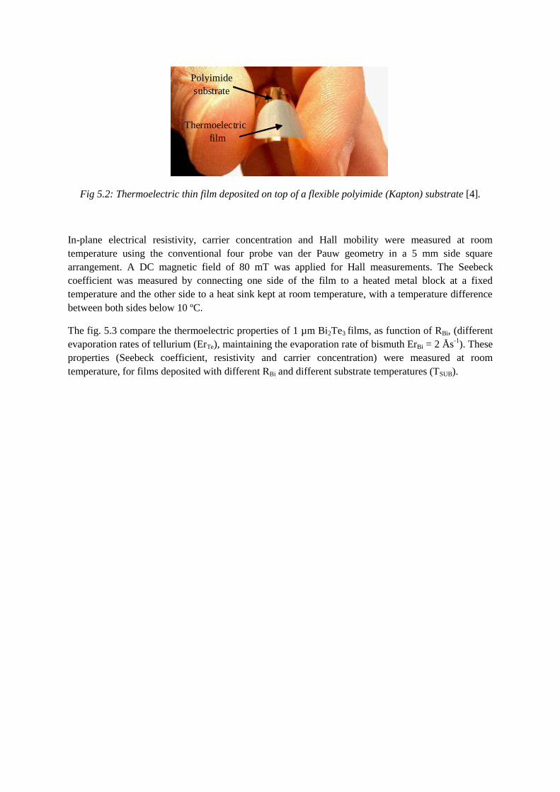
Polyimide substrate
Thermoelectric film
Fig 5.2: Thermoelectric thin film deposited on top of a flexible polyimide (Kapton) substrate [4].
In-plane electrical resistivity, carrier concentration and Hall mobility were measured at room
temperature using the conventional four probe van der Pauw geometry in a 5 mm side square
arrangement. A DC magnetic field of 80 mT was applied for Hall measurements. The Seebeck
coefficient was measured by connecting one side of the film to a heated metal block at a fixed
temperature and the other side to a heat sink kept at room temperature, with a temperature difference
between both sides below 10 ºC.
The fig. 5.3 compare the thermoelectric properties of 1 µm Bi2Te3 films, as function of RBi, (different
evaporation rates of tellurium (ErTe), maintaining the evaporation rate of bismuth ErBi = 2 Ås-1
). These
properties (Seebeck coefficient, resistivity and carrier concentration) were measured at room
temperature, for films deposited with different RBi and different substrate temperatures (TSUB).

Fig. 5.3: Seebeck coefficient, electrical resistivity, carrier concentration and power factor of Bi2Te3
thin films as a function of Te/Bi evaporation flow ratio, RBi (lines are guides to the eye)[7].
At each Tsub the maximum absolute value of the Seebeck coefficient is obtained at a value of RBi that
depends on Tsub. Maximum PF is obtained at RBi = 2, 2.5 and 3.5 respectively for Tsub = 190, 230 and
270 ºC. Films with compositions in Te richer than stoichiometric have lower carrier concentration (<
1020
cm-3
), higher mobility (> 50 cm2V
-1s
-1), and higher Seebeck coefficient, leading to a higher power
factor. Films obtained with RBi < 1.2 are Bi-rich and have high carrier concentration. This results in a
decreased value of power factor. High power factor correlates with a high absolute value of Seebeck
coefficient, with a low carrier concentration, and with a relatively low electrical resistivity. Since the
observed PFs dramatically decrease as the carrier concentration and electrical conductivity increase,
one is forced to conclude that these increments are the result of major changes in the band structure
and position of the Fermi level in the density of states (DOS). These changes are also responsible for
the observed decrease in α. In fact, according to the Mott theory of the Seebeck coefficient α,
critically depends on the derivative with respect to the energy of the DOS at the Fermi energy [7].
An equivalent behaviour is also found in Sb2Te3 films. Fig. 5.4 plots the main thermoelectric
properties of 1 µm Sb2Te3 films, when deposited at different substrate temperatures (TSUB = 150, 180
and 220 ºC) and RSb in the range 1.4 – 3.7, maintaining the Sb evaporation rate at 2 Ås-1
.
-300
-250
-200
-150
-100
-50
0
0.50 1.50 2.50 3.50 4.50 RBi
0
10
20
30
40
50
RBi
Res
isti
vit
y (
µΩ
m)
0
20
40
60
80
100
120
RBi
0.0
1.0
2.0
3.0
4.0
5.0
6.0
Po
wer
Fa
cto
r (x
10
-3 W
K-2
m-1
)
RBi
Tsub=190 ºC Tsub=230 ºC Tsub=270 ºC
0.50 1.50 2.50 3.50 4.50
0.50 1.50 2.50 3.50 4.50
0.50 1.50 2.50 3.50 4.50
See
bec
k c
oef
fici
ent
(µV
K-1
) C
arr
ier
Co
nce
ntr
ati
on
( x
10
19cm
-3)

Fig. 5.4: Seebeck coefficient, resistivity, carrier concentration and power factor of Sb2Te3 thin-films
as a function of Te/Sb evaporation flow ratio, RSb (lines are guides for the eye). [10]
The value of Seebeck coefficient and the value of electrical resistivity increases as RSb is increased.
The carrier concentration decreases with increase of RSb. No dependence was found on the Seebeck
coefficient or the carrier concentration with the substrate temperature (TSUB). However, the electrical
resistivity shows a strong dependence with TSUB. ρ < 15 µΩm is obtained with the substrate
temperature above 220 ºC. Films with compositions in Te richer than stoichiometric have lower
carrier concentration (n < 5×10¹⁹
cm-3
), higher mobility (μ > 100 cm2V
-1s
-1), and higher Seebeck
coefficient (α > 150 µVK-1
), leading to a high power factor.
The influence of substrate temperature (TSUB) in the power factor of co-evaporated Bi2Te3 and Sb2Te3
films [21] is presented in fig. 5.5. The results presented by Zou [2] and Silva [3], also for co-
evaporated films, are also presented in the same figure.
0
10
20
30
40
50
1.00 1.50 2.00 2.50 3.00 3.50 4.00
?.
RSb
Tsub=150ºC Tsub=180ºC Tsub=220ºC
0
50
100
150
200
250
1.00 1.50 2.00 2.50 3.00 3.50 4.00 RSb
Tsub=150ºC
Tsub=180ºC
Tsub=220ºC
0.0
0.5
1.0
1.5
2.0
2.5
3.0
1.00 1.50 2.00 2.50 3.00 3.50 4.00
Tsub=150ºC
Tsub=180ºC
Tsub=220ºC
0
5
10
15
20
25
30
1.00 1.50 2.00 2.50 3.00 3.50 4.00
) Tsub=150ºC
Tsub=180ºC
Tsub=220ºC
RSb
RSb
Res
isti
vit
y (
µΩ
m)
Po
wer
Fa
cto
r (x
10
-3 W
K-2
m-1
)
Ca
rrie
r C
on
cen
tra
tio
n (
x1
019cm
-3)
See
bec
k c
oef
fici
ent
(µV
K-1
)

Fig 5.5: Power factor of selected Bi2Te3 (left) and Sb2Te3 (right) films plotted as a function of
substrate temperature TSUB (lines are guides to the eye). Results from Zou [2] and Silva [3] are also
presented.
The chemical composition of the films and its structure were studied [23] by Energy-Dispersive X-ray
spectroscopy. The fig. 5.6 plots the power factor of co-evaporated Bi2Te3 and Sb2Te3 films, as
function of composition (atomic percentage of Te atoms in composition), for films deposited at three
different substrate temperatures (TSUB). The power factor of films deposited by Silva [3] using the
same deposition technique and the power factor of bulk single crystal of Bi2Te3 and Sb2Te3 [22] is
also presented in the same figure.
Fig 5.6: Power factor of Bi2Te3 (left) and Sb22Te3 (right) films deposited by co-evaporation plotted as
a function of composition and substrate temperature during deposition (TSUB) (lines are guides to the
eye). Results obtained in co-evaporated thin-films from Silva [3] and from single crystals [22] are also
presented.
In the graph of fig. 5.6, Bi2Te3 films present the maximum power factor at same composition (aprox.
65% Te) that single crystal Bi2Te3. However, the curve along the composition shows a broader peak,
probably due to polycrystalline structure of films. The power factor of Sb2Te3 films also presents the
same behaviour to those of bulk single crystal, when composition varies. The smaller power factor of
0
1
2
3
140 160 180 200 220 240 260 280
Substrate temperature TSUB (ºC)
Tsub=150ºC Tsub=180ºC Tsub=220ºC Silva Zou
Po
wer
facto
r P
F (
x10
-3 W
K-2
m-1
) Sb2Te3
0
1
2
3
4
5
6
160 200 240 300 Substrate temperature TSUB (ºC)
Po
wer
facto
r P
F (
x10
-3 W
K-2
m-1
)
Tsub=270ºC
Zou
Tsub=190ºC Tsub=230ºC
Silva
180 220 260 280
Bi2Te3
TSUB=150ºC TSUB=180ºC TSUB=220º
C
Silva
Single crystal
Composition (%Te)
55 60 65 70 75
0 0
1
2
3
4
Composition (%Te)
Po
wer
Fa
cto
r P
F (
x10
-3 W
K-2
m-1
)
1
2
3
6
5
4
TSUB=230ºC
TSUB=270ºC
Silva
Single crystal
Po
wer
Fa
cto
r P
F (
x10
-3 W
K-2
m-1
)
TSUB=190ºC
50 60 70 80
Bi2Te3 Sb2Te3

Sb2Te3 films, compared to bulk is probably due to polycrystalline structure that promotes high
electrical resistivity in interface regions.
Thermal conductivity (κ) was measured (in a direction parallel to film) on Bi2Te3 films (fig 5.7), for
temperatures between -20 ºC and 110 ºC, using the technique described by Völklein [23]. κ = 1.3 Wm-
1K
-1 was obtained at room temperature. Thermal conductivity is due to electron and phonon
contributions, respectively κe and κp, and κ = κe + κp [24]. Electron contribution was estimated using
Wiedemann-Franz law, κe = LT/ρe, where L is the Lorenz number, T the temperature and ρe is the
electrical resistivity. Considering L = 1.5 × 10⁻⁸
V2K
-2 at 300 K [25], κe = 0.45 Wm
-1K
-1 is obtained
(for a resistivity of 10 μΩm) and κp = 0.85 W m-1
K-1
. This value is smaller than κp = 1.03 Wm-1
K-1
for
bulk Bi2Te3 [26], due to reduced lattice contribution in polycrystalline structure. Using these values
and a Seebeck coefficient of 200 µVK-1
, a value of ZT near unity is obtained for the best Bi2Te3 thin
films at room temperature.
Fig. 5.7: Thermal conductivity and electrical resistivity of a Bi2Te3 film, measured from -20 ºC to 110
ºC [7].
Despite de composition, the structure of the thermoelectric thin film is also important to maximize the
figure of merit, as demonstrated before [7]. Thermoelectric Bi/Sb/Te films can be amorphous or
polycrystalline. Bulk material can also be found in form of single crystal. The interface regions
between crystals in a polycrystalline structure create additional electrical resistance, but also reduce
thermal conductivity, in such way that films with larger crystal grain have usually a lower resistivity
and higher thermal conductivity. The structure of films can be controlled by the substrate temperature
during deposition or with post-deposition annealing under controlled atmosphere. Due to
decomposition of Bi/Sb/Te compounds with temperature and the low vapour pressure of tellurium
(compared with Bi or Sb), this heating process can also alter the composition of films. During
deposition (pressure bellow 1×10⁻⁵
mbar), Te re-evaporates from substrate if temperature exceeds 200
ºC. This can be compensated with a higher evaporation rate of tellurium (beyond stoichiometric
composition). A low deposition rate of the films also promotes the growth of crystalline films, and
most important in the first film layers (bellow 100 nm). A low growth rate (1 Ås-1
) in the first 100 nm
of film, and increasing up to 6 Ås-1
, with heated substrate (200 – 300 ºC) achieves higher crystalline
structure (and decreases deposition time) than a constant deposition rate of 4 Ås-1
. In films thicker
than 1 µm, deposition rates can either go above 6 Ås-1
[21]. Other techniques allow faster growth of
films. Böttner [6] reported a deposition rate of 5 μm/h using co-sputtering and Snyder from the JPL
laboratory [8] fabricated a device with 20 μm high thermoelectric columns by ECD. Fig. 5.8 and 5.9
0
0.5
1.0
1.5
2.0
-20 0 20 40 60 80 100 120
0
5
10
15
20
25
Ele
ctr
ica
l R
esi
stiv
ity
(μ
Ωm
)
Thermal conductivity
Electrical resistivity
Th
erm
al
Co
nd
ucti
vit
y (
Wm
-1 K
-1)
Temperature (ºC)

shows the difractogram, obtained by X-ray diffraction (XRD) using copper Kα radiation
(λ=1.54051Å) of Bi2Te3 and Sb2Te3 films deposited by co-evaporation, respectively.
Fig. 5.8: XRD diffractograms of Bi2Te3 films deposited at substrate temperatures of 160 ºC (top line)
and 240 ºC (bottom line) [7].
Fig. 5.9: XRD diffractograms of Sb2Te3 films.
The observed peaks in fig. 5.8 agree with literature from powder diffraction spectra for polycrystalline
Bi2Te3, (card 15-863 [27]) or Bi0.43Te0.57 (card 22.715 [27]) and are represented in dashed lines.
Similar results are also found in literature for the same thermoelectric materials [3,5]. The substrate
temperature and the composition influences the peaks found in each film. In Fig 5.8, the two
difractograms of Bi2Te3 films were obtained with substrate temperatures of TSUB = 160 ºC and TSUB =
240 ºC.
0
1
2
3
4
5
6
7
15 20 25 30 35 40 45 50 55 60 65 70 2 θ (Deg)
log
in
ten
sity
(arb
.un
its)
Bi2Te3
TSUB=160ºC
TSUB=240ºC

Typical diffractograms of Sb2Te3 films are presented in fig. 5.9 from films #1, #2 and #3, respectively
deposited at TSUB = 220 ºC, TSUB = 150 ºC and TSUB = 220 ºC and RSb = 1.7, RSb = 1.7 and RSb = 2.5.
The planes with the higher X-ray intensities obtained with Sb2Te3 films deposited at TSUB = 220 ºC are
not the same as those from films deposited at TSUB = 150 ºC or from bulk Sb2Te3. The substrate
temperature during deposition influences both the structure and the orientation of Sb2Te3 thin-films.
Scanning electron microscopy cross-sectional and surface images of films, deposited at optimal
(substrate temperature and composition) conditions are presented in fig. 5.10. These images also
reveal the polycrystalline structure of film, and grains with dimensions above 500 nm are visible
[7,10]. With lower substrate temperature, the dimension of these grains is substantially reduced.
Fig. 5.10: Surface and cross-sectional images of a Bi2Te3 films with Tsub = 270 ºC and %Te = 62% (A
and C) and Sb2Te3 films with Tsub = 220 ºC and %Te = 70% (B and D), deposited on glass. A and B
films have thickness of 1 µm and C and D films have thickness of 5µm. [7,10]
Bi2Te3 Sb2Te3
A B
C D

3. Patterning of microdevices
The techniques used in the fabrication of micro thermoelectric devices were imported from the
fabrication of MEMS. The must used are wet-etching, lift-off, RIE and LIGA. Micropelt and IPM
Freiburg [6] used the RIE technique to pattern thick films of Bi/Sb/Te compounds, using photoresist
as an etching mask, using an Oxford-Instruments Bi2Te3 ICP etching process [28]. By other way, the
JPL laboratory [8] and Institut für Halbleiter und Mikrosystemtechnik [29] fabricated micro-columns
of TE materials using a LIGA process, with patterned photoresist and ECD deposition. Lift-off
patterning was implemented by the University of Michigan [30-32] . In this technique, thermoelectric
films were deposited on top of patterned SU-8 photoresist. The photoresist is then removed, removing
also the TE material on top of it, defining the structures. The maximum working temperature of SU-8
photoresist (≈180 ºC) limits the substrate temperature during deposition, thus reducing figure of merit
of Bi/Sb/Te films. Shafai [33,34] has reported on the possibility of using nitric acid (HNO3) and
hydrochloric acid (HCl) diluted in water (H2O) for etching Bi2Te3, but that work was not extended to
full characterization of the process, and it was not applied to other tellurium compounds. Recent work
from Sedky [35] also showed suspended Bi2Te3 microstructures fabricated by wet-etching. The use of
these etchants in the wet-etching patterning of thermoelectric structures was further studied [4,21,36],
using the structures of fig. 5.11. Thermoelectric Bi2Te3 and Sb2Te3 thin-films (1 µm thick) were
deposited on Kapton substrate. Transene’s PKP negative photoresist was applied on the surface and
test structures were patterned by wet-etching in HNO3:HCl:H2O etchant (pure HNO3 and 37% HCl
dil. in water). The effects of etchant composition and dilution in the etch rate are presented in figures
5.12 and 5.13.
Fig 5.11: Test structures of thermoelectric films patterned by wet-etching.
Fig. 5.12: Etch rate of Bi2Te3 and Sb2Te3 films in 10:3 HNO3:HCl solution, as a function of dilution
in water (% in volume) [36].
1
10
100
1000
40% 50% 60% 70% 80% 90% 100%
Etc
h r
ate
(n
m/s
) Good
Peeling
Too fast
%H2O
Bi2Te3
Sb2Te3
100 µm

Fig 5.13 Etch rate of Bi2Te3 and Sb2Te3 films in (1-x)HNO3:(x)HCl solution (diluted 70% in water, in
volume) [36].
The dilution of the etchant (% in volume) in water reduces the etch rate (fig. 5.12). Considering
dilutions bellow 70%, the etch rate is to fast (above 100 nm/s) and becomes difficult to accurately
control de etch time, occurring frequently over-etching. By the other side, if dilutions above 80% are
used, the large time needed for the film in the solution causes peeling of the film. Dilution around
70% is recommended [36]. Figure 5.13 shows the influence of etchant composition on the etch rates.
Higher percent of HCl (%HCl / %HNO3 > 0.5) induces cracking of the film and peeling occurs. Best
results are obtained with etchant composition in the range 10:1:20 to 10:5:40 HNO3:HCl:H2O. The
etch rate of Sb2Te3 films in diluted HNO3 (solution without HCl) was more than 50 times smaller
when compared with the etch rate of Bi2Te3 films in the same etchant. This is important in terms of
the selectivity of the process in the presence of both materials, etching Bi2Te3 with HNO3 while
leaving Sb2Te3 films untouched. However, this method cannot be used when BixSb2-xTe3 replaces
Sb2Te3. The etching attack in this solution on BixSb2-xTe3 is similar to that suffered by Bi2Te3, even
for small values of x.
For chromium and aluminium films using the same etching solutions used for tellurium compounds,
etch rates below 0.2 nm/sec were observed regardless of the etchant composition used. Both Bi2Te3
and Sb2Te3 are slightly etched (<2 nm/s) by aluminium etchant (16:1:1:2 phosphoric acid, nitric acid,
acetic acid and water) or Cr etchant (Transene 1020). This selectivity between all films and etchants
allows the fabrication of metallic contacts and thermoelectric elements by wet etching. Table 5.3
gathers together all relevant etch rates.
Table 5.3: Summary of etch rates [36].
Considering the eatch rates and selectivity presented, the fabrication process of thermoelectric
converters of fig. 5.14 can be implemented [36]. P-type Sb2Te3 film is first deposited followed by a
thin layer (100 nm) of nickel (a).The thin layers of nickel are used to avoid diffusion of thermoelectric
Material
Etchant
Bi2Te3
Sb2Te3
Aluminium
Nickel
Al – Transene type A 0.8 nm/s 0.5 nm/s 1-8 nm/s < 0.01 nm/s
Cr - Transene 1020 ≈ 2 nm/s <0.1 nm/s - 1-4 nm/s
3HNO3:1HCl (dil 70% H20) 200 nm/s 80 nm /s < 0.2 nm/s < 0.02 nm/s
HNO3 (dil 70% H20) 250 nm/s 5 nm/s < 0.01 nm/s < 0.01 nm/s
0
100
200
300
400
0.0 0.5 1.0 1.5 2.0 2.5 3.0 %HCl / %HNO3
Etc
h r
ate
(n
m/s
)
Good
Crack
Bi2Te3
Sb2Te3

material into the next deposited layers, promoting adhesion and avoiding large contact resistance.
Photoresist (PR) is spun and p-type elements are patterned by photolithography (b),(c). Nickel is
etched in a chromium etchant (Transene 1020), thermoelectric film is patterned by wet-etching in
HNO3:HCl bath (d) and PR is removed. N-type film is then deposited, followed by a 100 nm nickel
layer (e). PR is applied and patterned by photolithography for n-type element definition (f),(g). Nickel
is etched in a chromium etchant (Transene 1020), n-type film is etched in HNO3 (h) and PR removed
(i). Contacts are deposited, starting with a 100 nm layer of nickel, followed by 1 μm of aluminium (j).
PR is spun and contacts patterned by photolithography (k). Nickel is etched in a chromium etchant
(Transene 1020), and aluminium with a standard aluminium etchant (Transene type A). PR is
removed (l). A protective layer of Si3N4 can also be deposited by low temperature hot-wire chemical
vapour deposition (HW-CVD) [37] and patterned if required. Fig 5.15 shows a thermoelectric device
fabricated with wet-etching techniques.

Fig. 5.14: Fabrication steps of thermoelectric converters [36].
n
PR
Polyimide
PR
Mask
12-100μm
>20μm (b)
(c)
(d)
(e)
p-type TE
Polyimide
PR
p-type TE
10μm
Polyimide p
Polyimide p n n-type TE
Polyimide p n n-type TE
PR PR
Mask UV light
Polyimide p n n-type TE
Polyimide p n
PR
PR
Polyimide p n
PR
(f)
(g)
(h)
(i)
Develop PR
Etch Ni Etch p-type Strip PR
Deposit n-type + Ni
Deposit and pattern PR
Develop PR
Etch Ni Etch n-type
Strip PR
UV light
Etch Al Etch Ni Strip PR
n
n
Polyimide Deposit p-type + Ni p-type TE
Polyimide p n
(j)
Deposit Ni + Al
Polyimide p n
(k)
Deposit pattern and develop PR
Mask UV light
PR PR
Polyimide n p
100nmm
(a)
(l)

Fig. 5.15: Left: Photo of n-type and p-type elements, before deposition of top contacts. Right: Photo
of microcooler with 8 pairs of thermoelectric elements, fabricated with bottom contacts [36].
4. Applications
Using a lateral (in-plane) configuration [38,39], thin-film techniques can be used to scale down the
thermoelectric coolers and generators to microdevice dimensions. Planar thin-film technology [4,36]
can be used to fabricate such devices. The conventional thermoelectric cooler, with the heat flux
perpendicular to hot and cold areas, cannot be scalable to microchip dimensions, using the same
fabrication methods used for macro-scale devices. A new design topology [40], a thin-film planar
device, as shown in Fig 5.16, has lower heat-pump capacity, but a simplified fabrication process,
since all contacts are in the same plane.
Fig. 5.16: Planar thermoelectric device (left) and array of thermoelectric devices, fabricated in
Kapton foils.
Despite using figure of merit to quantify the quality of a thermoelectric material, this parameter can
also be used to quantify the performance of a thermoelectric device [40]. The figure of merit of a
thermoelectric device is calculated with eq. 1. Req and Keq are the equivalent electrical resistance and
thermal conductance of the device, calculated with eq. 2 and eq. 3.
eqeq
np
RKZ
2)( (Eq. 1)
pc
cp
nc
cn
pp
p
p
nn
nnceeq
WLWLHW
L
HW
LRRR
22 (Eq. 2)
Thermoelectric junctions on the hot side
Metal contact pads Kapton
substrate
n-type material
p-type material
Metal contact pads
Thermoelectric junctions on the cold side
L P-type
N-type
Metal pads
Hea
t flo
w dire
ctio
n
p-type Sb2Te3
n-type Bi2Te3

24 WL
HW
L
HW
L
HWK
m
mmm
p
pp
p
n
nnneq (Eq. 3)
Ln, Lp, Wn, Wp, Hn, Hp are respectively length, width and height of thermoelectric materials (n-type
and p-type) Lc is the length of contacts between TE material and metal pads, α is Seebeck coefficient,
ρ electrical resistivity, λ thermal conductivity and ρc contact electrical resistivity. The device is
supported by an isolating membrane, with thickness Hm, length Lm, width Wm and thermal
conductivity λm. γ represents a coefficient to include radiation and convection losses, in the range 5 <
γ <10 Wm2
K1
.
The previous equations can be used to predict the effect of reducing dimensions of a planar
thermoelectric device, from millimetres to micrometers. Besides the Seebeck coefficients (αn and αp),
the thermal conductivities (λn and λp) and electrical resistivities (ρn and ρp) of thermoelectric
materials, also the thermal conductivity of the supporting membrane (λm) and the contact resistance
(ρc) influences the performance of planar devices. And the effect of contact resistivity is more
pronounced (compared with electrical resistivities) as device dimensions get smaller.
The graph of fig 5.17 presents the effect of scaling down the dimensions of devices, in substrate plane
[40]. The scale factor f ˝ = 1 (in horizontal axis) represents a device with dimensions L = W = 1 mm,
H = 10 µm and Hm = 10 µm. Lower values of f represents devices where dimensions (L and W) were
reduced by a factor f, but same thickness (H) considered in thermoelectric materials and membrane.
Fig. 5.17: Effect of scaling the device in substrate plane. The height of device and support membrane
are constant (H =10 µm and Hm =10µm), while other dimensions are scaled by the value on
horizontal axis.
Since the losses by radiation and convection are less relevant in lower dimension devices, figure of
merit increases when device is smaller. However, a low contact resistivity must be ensured, to keep
this higher figure of merit. Considering both effects, an optimum dimension exists where figure of
merit is maximized [40].
4.1. Cooling Applications
A microcooler was fabricated on flexible polyimide Kapton© substrate. The polyimide substrate is
excellent for thermoelectric microcoolers in the lateral configuration, because of its small thermal
conductivity of 0.15 Wm-1
K-1
and its thermal expansion coefficient (about 20 10-6
K-1
) of the same
Losses due to
contact resistance
Losses due to convection and radiation

order of magnitude as that of the thermoelectric films, thus reducing thermal stresses induced during
cooling down from the temperature of deposition (200-300 ºC). Fig. 5.15 shows a thermoelectric film
deposited on top of a polyimide substrate. Since Bi2Te3 and Sb2Te3 adhesion is higher on Kapton
films than on nickel metal pads, the use of top contacts process (as presented in fig. 5.14) avoids the
need of depositing additional layers to promote adhesion of thermoelectric films.
The performance of the microcooler was analysed [41] by use of a thermal image map generated with
a microscope equipped with an infrared image sensor. An image [4] under vacuum was obtained with
the device excited with a 4 mA current, and cold and hot sides were clearly identified (fig. 5.18). A
temperature difference of 5 ºC between the hot and the cold sides was measured under vacuum (10
mtorr) and 4 ºC in still air conditions.
Pad s p - type
n - type
Fig. 5.18: Thermal image of n-type and p-type thermoelectric elements, powered with 4mA current,
under vacuum [4].
From the thermal image it is possible to conclude that thermal contact between the thermoelectric
elements and the metal pads is poor since the thermal gradient on this region is quite high, compared
with the gradient observed along metals or along thermoelectric elements. The 5 ºC hot-cold side
temperature difference obtained was lower than the value expected from the simulations. This
difference is due to electrical contact resistance, which is much higher than expected. Contact
resistance in this device was of the same order of magnitude as the resistance of the thermoelectric
elements (2 Ω). A small rectifying barrier voltage (less than 80 μV) was also measured on metal-
Bi2Te3 contacts.
4.2. Energy Harvesting Applications
This same planar device can be used to implement a thermoelectric generator. Previous work [42-44]
has demonstrated the maximum amount of thermal energy that can be removed from human-body in a
wearable thermal-generator without compromising the comfort, and maximizing the thermoelectric
conversion. A thermal resistance of 100-300 KW-1
cm2 is expected in the wrist, where thermal flow
can be converted with a thermo-bracelet. Also, temperatures between 27 ºC and 36 ºC can be found on
different parts of body. The ambient air temperature and thermal-converter to air thermal resistance
also limits the maximum power available. Thermal resistance bellow 50 KW-1
cm2 can be achieved
with a pin-heatsink. Maximum power output is obtained when the thermal resistance of the
thermoelectric generator is equal to the sum of human-body and heat-sink thermal resistances [45,46].

A thermal-resistance above 200 KW-1
cm2 is desirable in the thermoelectric converter. Fig. 5.19 shows
the open-circuit voltage and maximum power that can be obtained in a 1 cm2 Bi2Te3-Sb2Te3
thermoelectric generator, as function of length of the thermoelectric column (length L in fig. 5.16), in
a human-body generator, when a temperature difference of 10 ºC (air to body) is available, with 4000
pairs of p-n junctions.
Fig. 5.19: Open-circuit voltage and maximum power that can be obtained in a 1 cm2 Bi2Te3-Sb2Te3
thermoelectric generator, as function of length of the column (L), in a human-body generator, when a
temperature difference of 10 ºC (air to body) is available.
Since each thermoelectric junction of Bi2Te3-Sb2Te3 can deliver an output voltage of 300 μVK-1
, more
than 4000 junctions are necessary to obtain an output voltage (without load) of 10 V, under a
temperature difference of 10 ºC, when body and heat-sink thermal resistances are considered. To
obtain the desired thermal resistance of 200 KW-1
cm2, the thermoelectric elements should have length
of about 4 mm. The array of fig 5.16 can be used as a human body energy harvesting device, since
many junctions can be stacked in a single device and fabrication process allows the required 4 mm
length. Moreover, one of the ribs of fig. 5.16 can contain a solid-state rechargeable battery and
another rib the electronic circuit to extract maximum power from the thermoelectric generator and
control the charge of the battery [45-48]. Since many of wireless sensors are powered in a peak basis
(e.g., the transmission of data needs much more current than standby or receiving mode) and the
temperature gradient could not always be present, the energy is stored in a rechargeable thin-film
battery of Li-ion type (integrated in the system). Ultra-low power electronics performs DC-DC
rectification with a variable conversion factor (using MPPT, maximum power point tracking
algorithm) and recharge the battery on optimal conditions. Electronic circuits to perform this task are
commercial available [49].
Acknowledgments
The author would like to thank the Portuguese Foundation for Science and Technology
(FCT/PTDC/EEA-ENE/66855/2006) for funding this work. Also thank Professor F. Völklein
(University of Applied Sciences Wiesbaden) for thermal conductivity measurements, D.M. Rowe and
Gao Min (University of Cardiff) for guidelines in this work, P. Alpuim, J.H. Correia, C. Couto, A.G.
Rolo, J.P. Carmo, M.F. Silva and J. F. Ribeiro for their help in this work and meaningful discussions.
References
[1] L.W. da Silva and M. Kaviany, “Miniaturized thermoelectric cooler,” ASME
International Mechanical Engineering Congress and Exposition, New Orleans, USA,
2002, p. 1–15.
[2] H. Zou, D.M. Rowe, and S.G.K. Williams, “Peltier effect in a co-evaporated
Sb2Te3(P)-Bi2Te3(N) thin film thermocouple,” Thin Solid Films, vol. 408, Apr. 2002,
pp. 270-274.
[3] L.W. da Silva, M. Kaviany, and C. Uher, “Thermoelectric performance of films in the
bismuth-tellurium and antimony-tellurium systems,” Journal of Applied Physics, vol.
97, 2005, p. 114903.
[4] L.M. Goncalves, J.G. Rocha, C. Couto, P. Alpuim, G. Min, D.M. Rowe, and J.H.
Correia, “Fabrication of flexible thermoelectric microcoolers using planar thin-film
technologies,” Journal of Micromechanics and Microengineering, vol. 17, Jul. 2007,
p. S168-S173.
[5] D. Kim, E. Byon, G. Lee, and S. Cho, “Effect of deposition temperature on the
structural and thermoelectric properties of bismuth telluride thin films grown by co-
sputtering,” Thin Solid Films, vol. 510, Jul. 2006, pp. 148-153.
[6] H. Bottner, J. Nurnus, a Gavrikov, G. Kuhner, M. Jagle, C. Kunzel, D. Eberhard, G.
Plescher, a Schubert, and K.-H. Schlereth, “New Thermoelectric Components Using
Microsystem Technologies,” Journal of Microelectromechanical Systems, vol. 13, Jun.
2004, pp. 414-420.
[7] L.M. Goncalves, C. Couto, P. Alpuim, A.G. Rolo, F. Volklein, and J.H. Correia,
“Optimization of thermoelectric properties on Bi2Te3 thin films deposited by thermal
co-evaporation,” Thin Solid Films, vol. 518, 2010, p. 2816–2821.
[8] G.J. Snyder, J.R. Lim, C.-K. Huang, and J.-P. Fleurial, “Thermoelectric microdevice
fabricated by a MEMS-like electrochemical process.,” Nature materials, vol. 2, Aug.
2003, pp. 528-31.
[9] L.M. Goncalves, J. Rocha, J. Correia, and C. Couto, “Control of the Deposition Ratio
of Bi2Te3 and Sb2 Te3 in a Vacuum Evaporator for fabrication of Peltier Elements,”
2006 IEEE International Symposium on Industrial Electronics, Ieee, 2006, pp. 2773-
2777.
[10] L.M. Goncalves, P. Alpuim, and A.G. Rolo, J.H. Correia, “Optimization of
thermoelectric properties on Sb2Te3 thin films deposited by thermal co-evaporation,”
Thin Solid Films.
[11] J.R. Lim, G.J. Snyder, C.-K. Huang, J.A. Herman, M.A. Ryan, and J.-P. Fleurial,
“Thermoelectric microdevice fabrication process and evaluation at the Jet Propulsion
Laboratory (JPL),” Twenty-First International Conference on Thermoelectrics, 2002.
Proceedings ICT ’02., 2002, pp. 535-539.
[12] A. Giani, A. Boulouz, F. Pascal-Delannoy, A. Foucaran, E. Charles, and A. Boyer,
“Growth of Bi2Te3 and Sb2Te3 thin films by MOCVD,” Materials Science and
Engineering: B, vol. 64, Sep. 1999, pp. 19-24.
[13] A. Giani, F. Pascaldelannoy, A. Boyer, A. Foucaran, M. Gschwind, and P. Ancey,
“Elaboration of Bi2Te3 by metal organic chemical vapor deposition,” Thin Solid
Films, vol. 303, Jul. 1997, pp. 1-3.
[14] A. Boulouz, A. Giani, F. Pascal-Delannoy, M. Boulouz, A. Foucaran, and A. Boyer,
“Preparation and characterization of MOCVD bismuth telluride thin films,” Journal of
Crystal Growth, vol. 194, Jan. 1998, pp. 336-341.
[15] F. Volklein, “Transport properties of flash-evaporated (Bi1-xSbx)2Te3 films:
Optimization of film properties,” Thin Solid Films, vol. 187, 1990, pp. 253-262.
[16] A. Foucaran, A. Sackda, A. Giani, F. Pascal-Delannoy, and A. Boyer, “Flash
evaporated layers of (Bi2Te3–Bi2Se3)(N) and (Bi2Te3–Sb2Te3)(P),” Materials
Science and Engineering B, vol. 52, Apr. 1998, pp. 154-161.
[17] E. Kessler, A. Ihring, V. Baier, A. Franke, and U. Dillner, “Thin-film infrared
thermopile sensors with thermoelectric high-effective materials combination,” Proc.
11th Int. Conference SENSOR, Nurnberg, 2003, p. 249–254.
[18] M. Stordeur and I. Stark, “Low power thermoelectric generator-self-sufficient energy
supply for micro systems,” Thermoelectrics, 1997. Proceedings ICTʼ97. XVI
International Conference on, IEEE, 1997, p. 575–577.
[19] H. Zou, D.M. Rowe, and G. Min, “Growth of p- and n-type bismuth telluride thin films
by co-evaporation,” Journal of Crystal Growth, vol. 222, Jan. 2001, pp. 82-87.
[20] H. Bottner, J. Nurnus, A. Schubert, and F. Volkert, “New high density micro
structured thermogenerators for stand alone sensor systems,” 26th International
Conference on Thermoelectrics, IEEE, 2007, pp. 306-309.
[21] L.M. Goncalves, P. Alpuim, and J.H. Correia, “Fabrication of Thermoelectric Devices
by Applying Microsystems Technology,” Journal of Electronic Materials, vol. 39,
Jun. 2010, pp. 1516-1521.
[22] H. Scherrer and S. Scherrer, “Bismuth Telluride, Antimony Telluride, and Their Solid
Solutions,” CRC handbook of thermoelectrics, edited by D.M. Rowe, 1987, pp. 211-
237.
[23] F. Volklein and T. Starz, “Thermal conductivity of thin films-experimental methods
and theoretical interpretation,” Thermoelectrics, 1997. Proceedings ICTʼ97. XVI
International Conference on, IEEE, 1997, p. 711–718.
[24] C.M. Bhandari, “Minimizing the Thermal Conductivity,” CRC Handbook of
thermoelectrics, edited by D.M. Rowe, CRC Press, 1987, pp. 55-65.

[25] R. Venkatasubramanian, E. Siivola, T. Colpitts, and B. OʼQuinn, “Thin-film
thermoelectric devices with high room-temperature figures of merit.,” Nature, vol.
413, Oct. 2001, pp. 597-602.
[26] M. Stordeur, H.T. Langhammer, H. Sobotta, and V. Riede, “Valence Band Structure of
(Bi1-xSbx)2Te3 Single Crystals,” Physica Status Solidi (B), vol. 104, 1981, p. 513.
[27] Joint Committee on Powder Diffraction Standards, Powder Diffraction File, ASTM,
Philadelphia, PA, 1967.
[28] http://www.oxford-instruments.com/products/etching-deposition-
growth/processes/etch-processes/Pages/bi2te3.aspx, “Oxford Intruments.”
[29] W. Qu, M. Ploetner, and W.J. Fischer, “Microfabrication of thermoelectric generators
on flexible foil substrates as a power source for autonomous microsystems,” Journal of
Micromechanics and Microengineering, vol. 11, 2001, p. 146.
[30] L.W. da Silva and M. Kaviany, “Fabrication and measured performance of a first-
generation microthermoelectric cooler,” Journal of Microelectromechanical Systems,
vol. 14, Oct. 2005, pp. 1110-1117.
[31] B. Huang, C. Lawrence, A. Gross, G.-S. Hwang, N. Ghafouri, S.-W. Lee, H. Kim, C.-
P. Li, C. Uher, K. Najafi, and M. Kaviany, “Low-temperature characterization and
micropatterning of coevaporated Bi2Te3 and Sb2Te3 films,” Journal of Applied
Physics, vol. 104, 2008, p. 113710.
[32] G.S. Hwang, a J. Gross, H. Kim, S.W. Lee, N. Ghafouri, B.L. Huang, C. Lawrence, C.
Uher, K. Najafi, and M. Kaviany, “Micro thermoelectric cooler: Planar multistage,”
International Journal of Heat and Mass Transfer, vol. 52, Mar. 2009, pp. 1843-1852.
[33] C. Shafai and M.J. Brett, “A micro-integrated Peltier heat pump for localized on-chip
temperature control,” Proceedings of 1996 Canadian Conference on Electrical and
Computer Engineering, 1996, pp. 88-91.
[34] C. Shafai and M. Brett, “Optimization of BiTe thin films for microintegrated Peltier
heat pumps,” Journal of Vacuum Science & Technology A: Vacuum, Surfaces, and
Films, vol. 15, Sep. 1997, p. 2798.
[35] S. Sedky, A. Kamal, M. Yomn, H. Bakr, R. Ghannam, V. Leonov, and P. Fiorini,
“Bi2Te3 as an active material for MEMS based devices fabricated at room
temperature,” Solid-State Sensors, Actuators and Microsystems Conference, 2009.
TRANSDUCERS 2009. International, IEEE, 2009, p. 1035–1038.
[36] L.M. Goncalves, C. Couto, P. Alpuim, and J.H. Correia, “Thermoelectric micro
converters for cooling and energy-scavenging systems,” Journal of Micromechanics
and Microengineering, vol. 18, Jun. 2008, p. 064008.
[37] P. Alpuim, L.M. Goncalves, E. Marins, T. Viseu, S. Ferdov, and J. Bourée,
“Deposition of silicon nitride thin films by hot-wire CVD at 100° C and 250° C,” Thin
Solid Films, vol. 517, 2009, p. 3503–3506.

[38] D. Wijngaards, S. Kong, M. Bartek, and R. Wolffenbuttel, “Design and fabrication of
on-chip integrated polySiGe and polySi Peltier devices,” Sensors and Actuators A:
Physical, vol. 85, 2000, p. 316–323.
[39] G. Min and D.M. Rowe, “Cooling performance of integrated thermoelectric
microcooler,” Solid-State Electronics, vol. 43, May. 1999, pp. 923-929.
[40] L.M. Goncalves, R.P. Rocha, J.P. Carmo, and J.H. Correia, “Solid-state microcoolers
and thermal energy harvesting microsystems,” 2009 35th Annual Conference of IEEE
Industrial Electronics, Nov. 2009, pp. 4040-4044.
[41] L.M. Goncalves, J. Rocha, C. Couto, P. Alpuim, and J. Correia, “On-chip array of
thermoelectric Peltier microcoolers,” Sensors and Actuators A: Physical, vol. 145-146,
Jul. 2008, pp. 75-80.
[42] V. Leonov, P. Fiorini, S. Sedky, T. Torfs, and C. Van Hoof, “Thermoelectric mems
generators as a power supply for a body area network,” The 13th International
Conference on Solid-State Sensors, Actuators and Microsystems, TRANSDUCERS
’05., IEEE, 2005, pp. 291-294.
[43] R.J.M. Vullers, R. van Schaijk, I. Doms, C. Van Hoof, and R. Mertens, “Micropower
energy harvesting,” Solid-State Electronics, vol. 53, Jul. 2009, pp. 684-693.
[44] V. Leonov and R. Vullers, “Thermoelectric generators on living beings,” Proceedings
of the 5th European Conference on Thermoelectrics (ECT 07), 2007, p. 47–52.
[45] J.P. Carmo, R.P. Rocha, A.F. Silva, L.M. Goncalves, and J.H. Correia, “Integrated
thin-film rechargeable battery in a thermoelectric scavenging microsystem,” 2009
International Conference on Power Engineering, Energy and Electrical Drives, Mar.
2009, pp. 359-362.
[46] J.P. Carmo, L.M. Goncalves, and J.H. Correia, “Thermoelectric Microconverter for
Energy Harvesting Systems,” IEEE Transactions on Industrial Electronics, vol. 57,
Mar. 2010, pp. 861-867.
[47] J.P. Carmo, L.M. Goncalves, R.F. Wolffenbuttel, and J.H. Correia, “A planar
thermoelectric power generator for integration in wearable microsystems,” Sensors
and Actuators A: Physical, vol. 161, Jun. 2010, pp. 199-204.
[48] J.P. Carmo, J.F. Ribeiro, M.F. Silva, L.M. Goncalves, and J.H. Correia,
“Thermoelectric generator and solid-state battery for stand-alone microsystems,”
Journal of Micromechanics and Microengineering, vol. 20, Aug. 2010, p. 085033.
[49] http://www.cymbet.com/, “Solid-State Energy Storage for Embedded Energy, Power
Back-up and Energy Harvesting.”

List of Figures
Fig. 5.1: Vacuum chamber prepared for co-evaporation.
Fig 5.2: Thermoelectric thin film deposited on top of a flexible polyimide (Kapton) substrate [4].
Fig. 5.3: Seebeck coefficient, electrical resistivity, carrier concentration and power factor of Bi2Te3
thin films as a function of Te/Bi evaporation flow ratio, RBi (lines are guides to the eye) [7].
Fig. 5.4: Seebeck coefficient, resistivity, carrier concentration and power factor of Sb2Te3 thin-films
as a function of Te/Sb evaporation flow ratio, RSb (lines are guides for the eye) [10].
Fig 5.5: Power factor of selected Bi2Te3 (left) and Sb2Te3 (right) films plotted as a function of
substrate temperature TSUB (lines are guides to the eye). Results from Zou [2] and Silva [3] are also
presented.
Fig 5.6: Power factor of Bi2Te3 (left) and Sb22Te3 (right) films deposited by co-evaporation plotted as
a function of composition and substrate temperature during deposition (TSUB) (lines are guides to the
eye). Results obtained in co-evaporated thin-films from Silva [3] and from single crystals [22] are also
presented.
Fig. 5.7: Thermal conductivity and electrical resistivity of a Bi2Te3 film, measured from -20 ºC to 110
ºC [7].
Fig. 5.8: XRD diffractograms of Bi2Te3 films deposited at substrate temperatures of 160 ºC (top line)
and 240 ºC (bottom line) [7].
Fig. 5.9: XRD diffractograms of Sb2Te3 films.
Fig. 5.10: Surface and cross-sectional images of a Bi2Te3 films with Tsub = 270 ºC and %Te = 62% (A
and C) and Sb2Te3 films with Tsub = 220 ºC and %Te = 70% (B and D), deposited on glass. A and B
films have thickness of 1 µm and C and D films have thickness of 5µm. [7,10]
Fig 5.11: Test structures of thermoelectric films patterned by wet-etching.
Fig. 5.12: Etch rate of Bi2Te3 and Sb2Te3 films in 10:3 HNO3:HCl solution, as a function of dilution
in water (% in volume) [36].
Fig 5.13 Etch rate of Bi2Te3 and Sb2Te3 films in (1-x)HNO3:(x)HCl solution (diluted 70% in water, in
volume) [36].
Fig. 5.14: Fabrication steps of thermoelectric converters [36].
Fig. 5.15: Left: Photo of n-type and p-type elements, before deposition of top contacts. Right: Photo
of microcooler with 8 pairs of thermoelectric elements, fabricated with bottom contacts [36].
Fig. 5.16: Planar thermoelectric device (left) and array of thermoelectric devices, fabricated in Kapton
foils.
Fig. 5.17: Effect of scaling the device in substrate plane. The height of device and support membrane
are constant (H =10 µm and Hm =10µm), while other dimensions are scaled by the value on
horizontal axis.
Fig. 5.18: Thermal image of n-type and p-type thermoelectric elements, powered with 4mA current,
under vacuum [4].

Fig. 5.19: Open-circuit voltage and maximum power that can be obtained in a 1 cm2 Bi2Te3-Sb2Te3
thermoelectric generator, as function of length of the column (L), in a human-body generator, when a
temperature difference of 10 ºC (air to body) is available.
List of Tables
Table 5.1: Resume of deposition techniques for thermoelectric films.
Table 5.2: Properties of selected Bi2Te3 and BixSb2-xTe3 films.
Table 5.3: Summary of etch rates [36].