The Crazy Clutch Tutorial - Frontier Homepage …jcslocum/944/944 Clutch Replacement...This tutorial...
70
The Crazy Clutch Tutorial Performed and Written by Derek THANK YOU: -clarks-garage.com (i used their procedure to do my job since i had no instructions and could not have done it without them! -944online.com (For pretty much everything!) -Blacksea R&D (for various advice on the TT and a few short notice stuff) -Newhouse Manufacturing Inc -Various members along the way! Alright, the time has come for the clutch tutorial. First and foremost... I couldn't have done my clutch job without the help of members from a lot of different places and forums, clarks- garage.com *HUGE HUGE HELP*, Ian and his crew *ENORMOUS HELP!*, and my friends. My dad even came over to help me get the tranny in since it was so d**n heavy. Long story short, don't be afraid to ask for help! I am so insanely happy it's done. So let me start off by also mentioning that I am a VERY hands on person so a lot of the pictures are going to be of things I thought were critical that you would need to keep an eye on or know about. If you have any questions feel free to ask. I am going to try and do it as detailed as possible here... This tutorial will cover everything from your clutch replacement, to your torque tube rebuild. Why? Because likelihood is that if your 944 is as old as mine (and it is) and your clutch was as old as mine (and it probably is if you are reading this) then the likelihood that your bearings are probably just as bad if not close to being there. Why do it in one big swoop? Because if you do it later you will end up back down there sooner or later. First off here is a list of ALL tools you will need to do this job. - 2 jacks (you /could/ do it with one but having an extra jack when it's time to do the tranny is going to be a huge help) - Numerous sockets and ratchets (8mm, 10mm, 13mm *probably used the most*, 17mm, 19mm, 22mm *O2 sensor*, cheese-head tools 8 and 12mm, Allen-head sockets (of various sizes) - Breaker bar or some sort of electric air gun (or just an air gun) - Torque wrench measuring in ft lbs (150ft lbs preferred, but you can probably get away
Transcript of The Crazy Clutch Tutorial - Frontier Homepage …jcslocum/944/944 Clutch Replacement...This tutorial...

The Crazy Clutch Tutorial
Performed and Written by Derek
THANK YOU:
-clarks-garage.com (i used their procedure to do my job since i had no instructions and
could not have done it without them!
-944online.com (For pretty much everything!)
-Blacksea R&D (for various advice on the TT and a few short notice stuff)
-Newhouse Manufacturing Inc
-Various members along the way!
Alright, the time has come for the clutch tutorial. First and foremost... I couldn't have done
my clutch job without the help of members from a lot of different places and forums, clarks-
garage.com *HUGE HUGE HELP*, Ian and his crew *ENORMOUS HELP!*, and my friends.
My dad even came over to help me get the tranny in since it was so d**n heavy. Long
story short, don't be afraid to ask for help! I am so insanely happy it's done.
So let me start off by also mentioning that I am a VERY hands on person so a lot of the
pictures are going to be of things I thought were critical that you would need to keep an eye
on or know about. If you have any questions feel free to ask. I am going to try and do it as
detailed as possible here...
This tutorial will cover everything from your clutch replacement, to your torque tube rebuild.
Why? Because likelihood is that if your 944 is as old as mine (and it is) and your clutch was
as old as mine (and it probably is if you are reading this) then the likelihood that your
bearings are probably just as bad if not close to being there. Why do it in one big swoop?
Because if you do it later you will end up back down there sooner or later.
First off here is a list of ALL tools you will need to do this job.
- 2 jacks (you /could/ do it with one but having an extra jack when it's time to do the
tranny is going to be a huge help)
- Numerous sockets and ratchets (8mm, 10mm, 13mm *probably used the most*, 17mm,
19mm, 22mm *O2 sensor*, cheese-head tools 8 and 12mm, Allen-head sockets (of various
sizes)
- Breaker bar or some sort of electric air gun (or just an air gun)
- Torque wrench measuring in ft lbs (150ft lbs preferred, but you can probably get away

with 100ft lbs) and another torque wrench measuring in up to 50ft lbs (most torque
wrenches start at 50 and go up to 150. You will need one that is capable of reading as low
as 11ft lbs for some bolts! if you have one that does it all then power to ya!)
- U-Joint adapter for your sockets and various extensions both of long length and of short
length
- screwdrivers of course
- Lithium grease to lube up parts on the clutch
- Prybars (recommended)
- Retaining clip pliers
- Huge hammers and some pliers of various sorts
- Slide-hammer or homemade slide-hammer of some sort (for pilot bearing because it's
really annoying)
- Align tool for clutch (HIGHLY RECOMMENDED)
Alright. So let's get started. First thing is first. JACK UP THE CAR and put it on stands. At
some point you WILL be dropping the suspension so You are going to need to put the rear
jacks up near where the suspension bolts in (the big huge 19mm bolts) reason for this is
that later once you drop the suspension the jack won't be in the way.
DISCONNECT YOUR BATTERY CABLES.
Now... you will need to remove your exhaust. There is no way that you can get to
everything without doing so. You will need a 13mm wrench and socket and take off all 6
bolts and nuts off of the part that connects the exhaust to the header at the 2 way.

Do not forget your O2 sensor and your line that is for O2 smog testing. In this case, my
line was a pain to get off so I hacked mine off and had a plug made at a shop so it was
easier to go back in and have less things hanging off my car.

This is what mine looked like when I got it off. Obviously you should not install it back like
this. But you can bring the screw on adapter to a shop and have someone weld it shut and
then tighten it back on and then bam, instant plug.
You will then have 2 hangars that hang off of rubber stoppers and two 13mm nuts for each
hangar, there will be 2 more nuts/bolts at the rear of the exhaust where the muffler sits as
well. It should then drop down and slide under. Put it somewhere safe!
With the exhaust out of the way you need to get everything else out of the way. There is

the heat shield for the exhaust and then 2 brackets (they are gone out of this picture, and
removed, this is what it looks like with them removed. There will be 4 13mm nuts and
some philips head screws holding the heat shield in. There will then be 8 small 13mm bolts
holding in the brackets.
Make sure all the hangars are actually off the torque tube as they will get in the way when
taking it out.
Make sure to disconnect the starter AND the slave cylinder. The slave will have two 13mm
bolts holding it in. The starter will have two 17mm or 19mm bolts holding it in followed by
an 8mm nut and 13mm nut holding on the wires.
From here we need to remove the transmission. To do this there will be a few wires at the
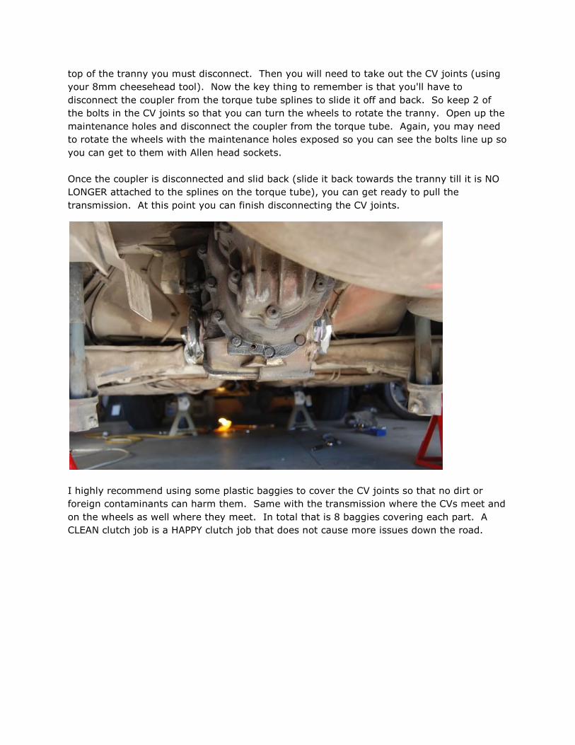
top of the tranny you must disconnect. Then you will need to take out the CV joints (using
your 8mm cheesehead tool). Now the key thing to remember is that you'll have to
disconnect the coupler from the torque tube splines to slide it off and back. So keep 2 of
the bolts in the CV joints so that you can turn the wheels to rotate the tranny. Open up the
maintenance holes and disconnect the coupler from the torque tube. Again, you may need
to rotate the wheels with the maintenance holes exposed so you can see the bolts line up so
you can get to them with Allen head sockets.
Once the coupler is disconnected and slid back (slide it back towards the tranny till it is NO
LONGER attached to the splines on the torque tube), you can get ready to pull the
transmission. At this point you can finish disconnecting the CV joints.
I highly recommend using some plastic baggies to cover the CV joints so that no dirt or
foreign contaminants can harm them. Same with the transmission where the CVs meet and
on the wheels as well where they meet. In total that is 8 baggies covering each part. A
CLEAN clutch job is a HAPPY clutch job that does not cause more issues down the road.

Here is the tricky part.. it is VERY hard to balance with a regular jack. It can be done but
takes some good positioning. In short, get a tranny jack if you can or use something to cup
the tranny so it comes STRAIGHT down. Otherwise you get to muscle it out. It is
recommended to disconnect your fuel line and fuel filter prior to doing this so you do not
mangle it, however, I did not, and had no issues. However, as a disclosure, please be
careful and take any precautions you deem necessary. If you mess it up, don't say I didn't
tell you so.
You will need to also disconnect the shift linkage; it will have a retaining bolt in it that is
13mm with a nosed end in the rod. It more than likely will have safety retaining wire in it
which you will need to remove so you can get at it. Then slip the linkage off and as far back
in the tube as you can. Once you have done this, disconnect your shifter and the
two 13mm bolts that hold it to the torque tube. Once you've completely disconnected the
shifter from the linkage (should have a retaining clip on it) you can slide the linkage out
from under it and push it forward so it is not hanging the transmission when it comes time
to lower it.
To lower the transmission begin by bracing the bottom of the transmission with the jack.
The transmission will have 4 big bolts holding it to the housing of the torque tube, they
should be 19mm and possibly 17mm. With the jack FULLY supported (and be careful so it
does not teeter or move on you and crash off the jack) undo the 2 big 17mm bolts at the
top of the transmission mounts and slooooowly lower it down. Again, I cannot stress the
importance of balancing the transmission properly since it is very heavy in the back.
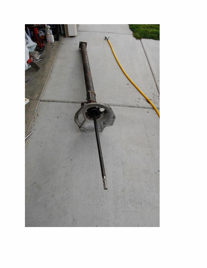
Once the tranny is out it should look like this:

Here is what you will see once the torque tube is hanging.
Now... we are approaching the part where we start getting ready to do the clutch. I am
going to go in the order I went in which was to do the torque tube last. So we are actually
only going to disconnect it and do the suspension later. Why? Because the torque tube is a
pain in the butt and you'll feel more productive if you do the clutch first.

That said: At this point we should recap to make sure the following has been done.
- slave cylinder is out
- starter is out
- exhaust is off
- tranny is out
- CV joints all disconnected
- torque tube should be hanging by itself
- shift linkage removed (at this point you can pull it out of the way and out of the car if you
want for more space)
Our next step is going to be to support the engine. I used 4x4 boards. You can use an
extra jack if you wish but use something soft so you do NOT damage your oil pan. At this
point you will want to disconnect the 4 bolts holding the torque tube on (should be 17mm
bolts, might be 19mm bolts)
Once the 4 bolts are disconnected from the torque tube, you should be able to disconnect it
and slide it out of the bell housing. Depending on the age of your clutch, how rusted up
stuff is inside it may give you some grief. Pop a few cans of spinach and let the torque tube
rest on the suspension, then go up near the bell housing and use nice even tugs. This is so
that you are supporting the end of the shaft and not putting pressure on it while the torque
tube rests on the other end. If someone else can pull on the other end of the TT housing
while you hold it you can try that too. It should literally just slide out nice and easy. Do
NOT drop the torque tube and make sure when you let the torque tube rest that you watch
the housing (if you did not remove the fuel filter and line the edge of the housing can nick it
and destroy it!)
This is the part where you need to be careful. I rested mine up near the brace where the
transmission bolts in, the edge of the housing acted as a leverage and the torque tube just
hung there. A smarter way to do it would be to rest it on some blocks or a jackstand on the
other end. The other danger of this is that if you accidentally bump it or knock it over, you
may end up hitting a line. Whichever you do, disclosure, be careful!
Visual example of edge of housing resting near brace.

Now we need to prepare removing the bellhousing. This can be a real pain. First off, you
need to disconnect the 2 reference sensors on the top of the bellhousing. I would
recommend ONLY disconnecting the sensors and not the housing for the sensors or you
have to go back and adjust them. When removing them I must stress that you need to
TAKE YOUR TIME. I hear about people breaking these on forums all the time. My method
was to take remove the 10mm bolts from the top (CAREFULLY you do NOT want to drop
them in the bellhousing window!) and then use a pair of pliers and carefully CAREFULLY
rotate them. They may be sticky or somewhat stuck. SHoot some pb blaster down on
them if they don't want to budge go relax and come back in an hour and try it again. If you
can get them to wiggle by rotating them then you can slowly wiggle them out by rotating
from left to right as you pull and slowly they will come out. Do not apply any force that
could bend them as they could snap.
Now remove the ground strap from the bellhousing (13mm bolt, will hold a thick gauge red
wire and your ground strap coming from the firewall). From here you will need to use a
10mm wrench or socket and remove the starter strap from the bellhousing (should have 2
places where it bolts on) and I would recommend also the strap that holds the line for the
slave cylinder so you can move the line out of the way so you don't mash it.
Let's do a quick recap on removing the bellhousing on all interference items that will
prevent removal:
- Ground strap and ground cable
- Straps for starter wires
- Strap for slave cylinder line
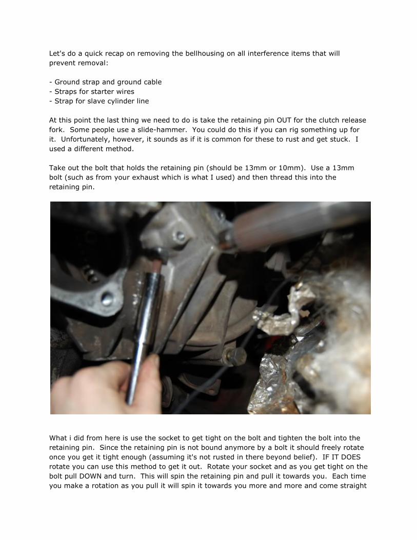
At this point the last thing we need to do is take the retaining pin OUT for the clutch release
fork. Some people use a slide-hammer. You could do this if you can rig something up for
it. Unfortunately, however, it sounds as if it is common for these to rust and get stuck. I
used a different method.
Take out the bolt that holds the retaining pin (should be 13mm or 10mm). Use a 13mm
bolt (such as from your exhaust which is what I used) and then thread this into the
retaining pin.
What i did from here is use the socket to get tight on the bolt and tighten the bolt into the
retaining pin. Since the retaining pin is not bound anymore by a bolt it should freely rotate
once you get it tight enough (assuming it's not rusted in there beyond belief). IF IT DOES
rotate you can use this method to get it out. Rotate your socket and as you get tight on the
bolt pull DOWN and turn. This will spin the retaining pin and pull it towards you. Each time
you make a rotation as you pull it will spin it towards you more and more and come straight

down. I've heard of some people using prybars, others using screwdrivers to pry and some
using slidehammers. NONE of those worked for me but the twisting method did. Whichever
method you use, just stick with what works. It IS long, so expect it to take a few.
The last thing at this point will be the bolts that hold the bellhousing on. You will have
various 17mm bolts holding it on. The bolts on the bottom should be easy cheesy. The
ones on the top of the bellhousing can be tricky. I recommend a ratcheting wrench that
rotates to get at them that is of good length, this makes it a lot easier.
The one bolt I had a tough time with was the middle driver side bolt. It sits up at an angle
that is near the brake lines, the bellhousing, and the rest of the body of the car. This
makes it tight quarters. You will need a U-Joint adapter to attach to the socket and several
long extensions to get at this sucker. It is a real pain. Mine used an astronomical amount

of force to hold it in. I braced the ratchet up against the area where the torque tube sat
and pressed hard as I could with my foot (it took that much force) although you may be
lucky and not have to work so hard.
With all the bolts out a quick recap:
- Bolts out
- Retaining pin out
- All wires and grounds disconnected from bellhousing
- Any extra straps disconnected.
- Speed and reference sensor totally disconnected
- Nothing at this point should be connected to the bellhousing.
Now you should be able to wiggle the bellhousing around. With a little finesse and work it
should pop right off, but you may have to work the angles on it to get it to slide out the way
you want it. Things at the top of the bellhousing are a bit of a pain.
Once the bellhousing is off you should see something like this, but much more rusty and
nasty.
You can see that you will have various allen head bolts holding on the pressure plate. 9

total. Take these off. Some people say you need to brace the flywheel to do so. Mine were
rusted and nasty, and my method involved quick jerking movements. I used the very end
of my ratchet and swung it quickly with some force and the bolts broke loose every time
and from there they were nearly finger loose. Very easy to do. If they do require force
then try a quick jerking swing to "tighten" then reverse it and a quick jerking swing to
loosen it. This should get them off.
Remove the pressure plate and clutch. You should see this. This is your flywheel.
The pressure plate is a bit more tricky. These bolts are in a lot harder than the pressure
plate bolts. I used an electric air gun since they use far less torque than a high volume air
gun you would use on a compressor. Alternatively if you have a long breaker bar or torque
wrench you can use it as leverage and use the same jerking motions to get them off. I
found that in using my electric air gun that if they didn't immediately loosen up I could try
tightening then going back to loosen on the gun which would make them move enough to
stop binding. The other thing you can do is to use a small rod or screwdriver and put it in
one of the side holes of the flywheel to brace it up against something which will hold it still,
then you can loosen them easily.
BE VERY CAREFUL TAKING THE FLYWHEEL OFF. DO NOT DAMAGE THE SURFACE, SCRATCH
IT, OR LET ANYTHING TOUCH IT. GO WRAP IT UP IN A TOWEL AND PUT IT AWAY
SOMEWHERE SAFE!
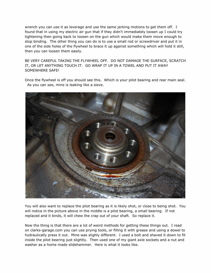
Once the flywheel is off you should see this. Which is your pilot bearing and rear main seal.
As you can see, mine is leaking like a sieve.
You will also want to replace the pilot bearing as it is likely shot, or close to being shot. You
will notice in the picture above in the middle is a pilot bearing, a small bearing. If not
replaced and it binds, it will chew the crap out of your shaft. So replace it.
Now the thing is that there are a lot of weird methods for getting these things out. I read
on clarks-garage.com you can use prying tools, or filling it with grease and using a dowel to
hydraulically press it out. Mine was slighly different. I used a bolt and shaved it down to fit
inside the pilot bearing just slightly. Then used one of my giant axle sockets and a nut and
washer as a home made slidehammer. Here is what it looks like.
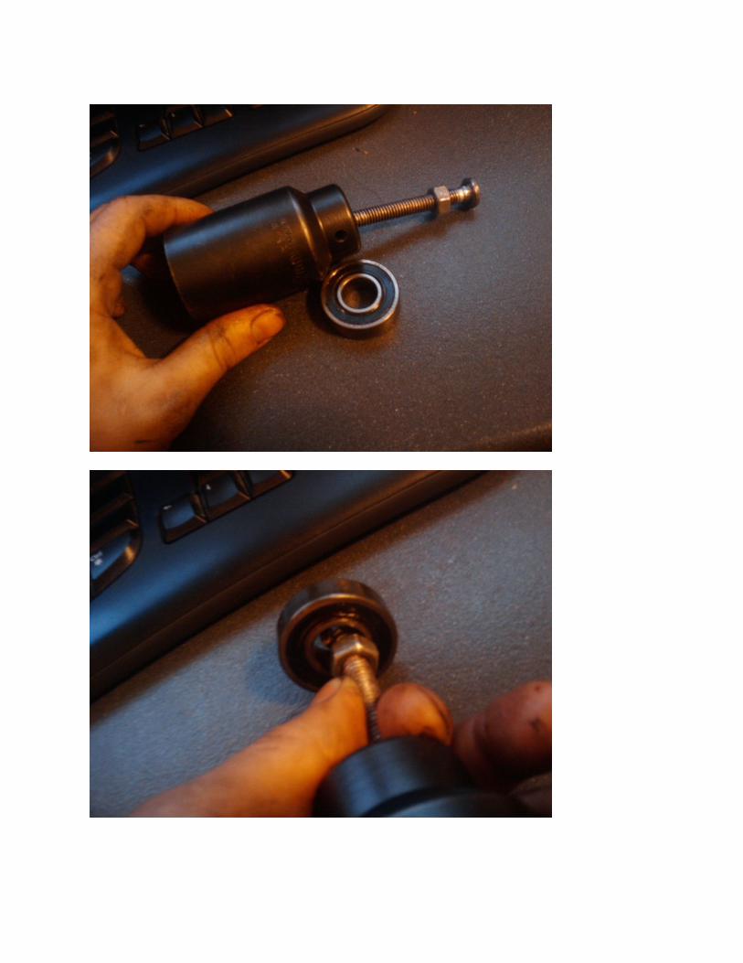


The trick to using this is that I used the bolt end on one side to edge the lining of the race
on the bearing and then used the nut on the other side to tighten it so it held tight on the
race. Then I gave it my all and swung the crap out of it in the motion of a slidehammer.
Amazingly, it came out quite quickly this way!
I HIGHLY recommend replacing the pilot bearing it's really not that bad to get out if you use
the above technique.
I also recommend replacing the rear main seal. They are a pain to get out, in fact, using
the pry technique where it has an indent to pry it out hardly worked. It is okay to mangle
the seal to get it out, you're replacing it! Just don't damage the crankshaft or the casing
where the seal sits! I would say "use this technique" but I literally pried, pulled, split, and
jerked on it till it was out.
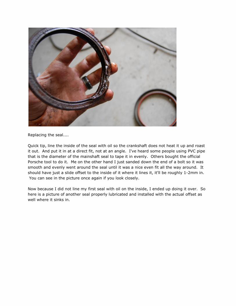
Replacing the seal....
Quick tip, line the inside of the seal with oil so the crankshaft does not heat it up and roast
it out. And put it in at a direct fit, not at an angle. I've heard some people using PVC pipe
that is the diameter of the mainshaft seal to tape it in evenly. Others bought the official
Porsche tool to do it. Me on the other hand I just sanded down the end of a bolt so it was
smooth and evenly went around the seal until it was a nice even fit all the way around. It
should have just a slide offset to the inside of it where it lines it, it'll be roughly 1-2mm in.
You can see in the picture once again if you look closely.
Now because I did not line my first seal with oil on the inside, I ended up doing it over. So
here is a picture of another seal properly lubricated and installed with the actual offset as
well where it sinks in.


Quick recap:
- Mainseal has been replaced.
- Pilot bearing replaced
- Clean the crap out of it down there!
Now to repair the release fork. Those bearings likely are either very hard to move,
completely bound, or may have even destroyed your retaining pin. The fork itself is more
than likely fine but you do need to replace those bearings!
You might be looking at it going "how the hell do i get those things out?"
You have a few options. Someone can press them out for you at a machine shop or you can
tap them out. I tapped mine in and out both and did no damage to them. HOWEVER, you
need to be gentle and VERY CAREFUL.
I used the back end of a bolt that was about the diameter of the bearings, I believe it was
17mm.
I then braced it on a table and gave the bolt end a good smack over and over till the
bearings popped out the other end.

I used the same technique to put them back in. Be warned, the ends of the bearings are
somewhat soft. If you hit it too hard you may curl them and potentially eat into the inside
race where the needle bearings spin, therefore causing it not to work correctly and then
you've got issues. I did also use more lubrication since it is easy to accidentally remove
some of the grease with your fingers and testing them on the retaining pin. I used generic
grease but I would also recommend probably using the lithium grease instead.

The next step is to either replace your flywheel or have it turned. If you have it turned they
may want to step it, this is where they remove material from the wear surface where the
disc met the flywheel and then remove equal material from where the pressure plate sits. I
had mine done this way and it has operated as intended. Here are the dimensions to stick
to:
(special thanks to Rastamonsta from 924board.org for this info!)
- Wear limit thickness is 11.8mm on flywheel (this is from the back of the flywheel to the
wear surface)

- Remove as LITTLE material as possible
- Max runout for surface material is .05mm
With this done your flywheel should look like this:

The pressure plate should not be machined or re-used. Get a new one.
Assembling it can be confusing if you've never done it before. I was told by Ian and Steve
to use the SAME SPACER COUNT from the stock pressure plate for the new one. Here is
what I mean...
First off, here is the old pressure plate. In this picture I have begun taking the old throwout
bearing out (hence the cut marks)
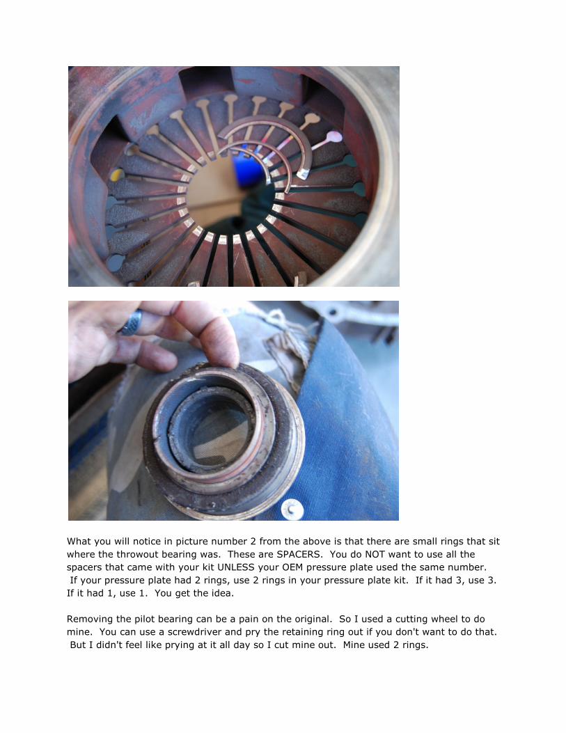
What you will notice in picture number 2 from the above is that there are small rings that sit
where the throwout bearing was. These are SPACERS. You do NOT want to use all the
spacers that came with your kit UNLESS your OEM pressure plate used the same number.
If your pressure plate had 2 rings, use 2 rings in your pressure plate kit. If it had 3, use 3.
If it had 1, use 1. You get the idea.
Removing the pilot bearing can be a pain on the original. So I used a cutting wheel to do
mine. You can use a screwdriver and pry the retaining ring out if you don't want to do that.
But I didn't feel like prying at it all day so I cut mine out. Mine used 2 rings.

Now.. I'd recommend replacing your throwout bearing. Again, using the number of rings,
we need to assemble in order.
Pressure plate first.
Get all your materials ready.
Pilot bearing slides in first with the big washer. Install your spacers FIRST

Now install the big washer, please note the direction it is pointing and installed.
Slide it through the pressure plate carefully (keep in mind not to let anything damage the
surface material! sit everything on a towel is recommended, or a soft surface) - you will
then slide the locking adapter through the back over it as seen here, note it has a groove
for the retaining clip.

Now you will see the clip blurred in this picture. Insert the clip into the locking adapter.
Using a screwdriver you can pry the clip into the groove. Or if you have a good set of
retaining clip pliers you can use those to install it properly.

At this point it should have completely snapped in and be in place.

If it was installed correctly you can sit it on the bearing and give her a good spin, make sure
it's smooth and listen for any binding in the bearing to ensure it is not defective.
Make sure to clean up the ring gear and remove it from the old pressure plate and install it
to the new one (this is what your starter turns and has the teeth in the picture)
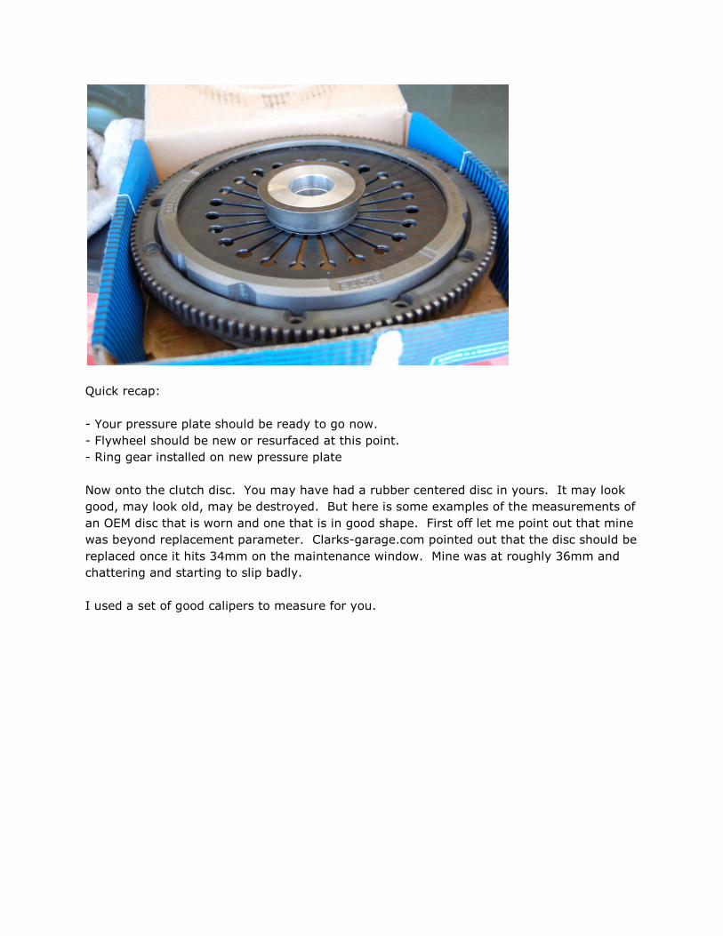
Quick recap:
- Your pressure plate should be ready to go now.
- Flywheel should be new or resurfaced at this point.
- Ring gear installed on new pressure plate
Now onto the clutch disc. You may have had a rubber centered disc in yours. It may look
good, may look old, may be destroyed. But here is some examples of the measurements of
an OEM disc that is worn and one that is in good shape. First off let me point out that mine
was beyond replacement parameter. Clarks-garage.com pointed out that the disc should be
replaced once it hits 34mm on the maintenance window. Mine was at roughly 36mm and
chattering and starting to slip badly.
I used a set of good calipers to measure for you.

This is a picture of the OEM disc vs a replacement disc (the italian aftermarket disc
available)

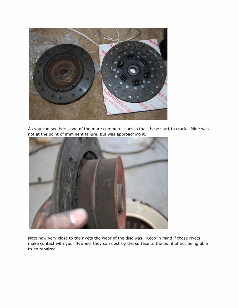
As you can see here, one of the more common issues is that these start to crack. Mine was
not at the point of imminent failure, but was approaching it.
Note how very close to the rivets the wear of the disc was. Keep in mind if these rivets
make contact with your flywheel they can destroy the surface to the point of not being able
to be repaired.

This is the measurement of the OEM disc.
This is the measurement of the aftermarket italian disc. Note how much more surface
material there is measured.

Measured in 10ths of an inch you will note that the original disc was at just under 3/10thsof
an inch. The aftermarket was 4/10ths or 2/5ths of an inch. That is about another 10th of
an inch in friction material. That doesn't sound like much, but you would be amazed how
far a disc can wear over time!
Up against the italian disc with the calipers at the OEM setting
Now there is not anything special to do on the disc, just buy a new one. I don't recommend
getting a used one unless you enjoy replacing them again sooner than later. I also would
recommend a sprung clutch like the italian disc I show above since it is not prone to the
rubber cracking.

Now to put it all back together!
First off is recap... again, let's be sure we are READY to continue and have not forgot
anything!
- Your pilot bearing should be replaced
- Main seal
- Surfaces cleaned off in area where flywheel is to be replaced
- Pressure plate ready to go
- New disc ready to go
- Alignment tool ready to go
- All new hardware (bolts for flywheel and pressure plate) ready to go
- Flywheel ready to go
If you have all this ready... you're good to go.
First thing is the flywheel. Again you will need to use the technique of holding it still for the
bolts more than likely by inserting a small rod or screwdriver in one of the holes to hold it
still. Again, do NOT touch the surface of the flywheel and do NOT damage it.
Torque all of the flywheel bolts using your 12mm cheesehead to 65ft lbs.
Using the recommended grease, line the inner race of the pilot bearing.
With your alignment tool handy, put the disc in and then put the pressure plate on. Insert
your alignment tool. In an EVEN manner I did my middle bolts first (do NOT tighten just
start them and slowly snug up) and work your way to the outer bolts. Ensuring that your
alignment tool is holding the clutch dead center.
Torque the pressure plate bolts to 18ft lbs each. Again, starting with the center bolts. Then
the outer bolts. Once this is down go over them one more time with the torque wrench to
ensure they are 100% all torqued down properly.
I CANNOT STRESS ENOUGH how important it is to tighten these up in a triangular pattern.
If the pressure plate is NOT installed with even pressure you may end up with a bunked
install and it may ruin the clutch or clamping force. TRIANGULAR PATTERN of tightening.
First with middle bolts, then outer bolts. Do not tighten them down, just finger tight or
finger snug until all bolts are even. Then tighten in a triangular fashion. Double check
torque.
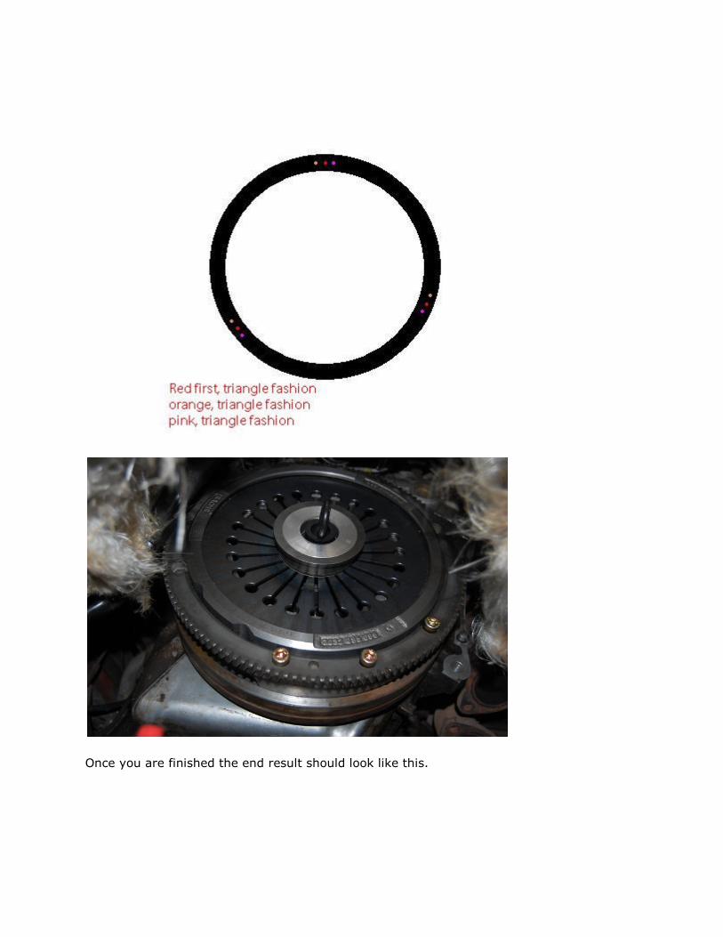
Once you are finished the end result should look like this.

I recommend going to the back where the torque tube is and ensuring it looks straight.
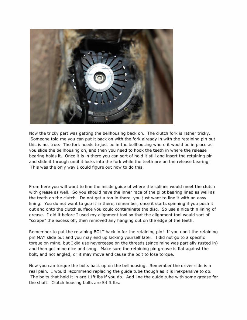
Now the tricky part was getting the bellhousing back on. The clutch fork is rather tricky.
Someone told me you can put it back on with the fork already in with the retaining pin but
this is not true. The fork needs to just be in the bellhousing where it would be in place as
you slide the bellhousing on, and then you need to hook the teeth in where the release
bearing holds it. Once it is in there you can sort of hold it still and insert the retaining pin
and slide it through until it locks into the fork while the teeth are on the release bearing.
This was the only way I could figure out how to do this.
From here you will want to line the inside guide of where the splines would meet the clutch
with grease as well. So you should have the inner race of the pilot bearing lined as well as
the teeth on the clutch. Do not get a ton in there, you just want to line it with an easy
lining. You do not want to gob it in there, remember, once it starts spinning if you push it
out and onto the clutch surface you could contaminate the disc. So use a nice thin lining of
grease. I did it before I used my alignment tool so that the alignment tool would sort of
"scrape" the excess off, then removed any hanging out on the edge of the teeth.
Remember to put the retaining BOLT back in for the retaining pin! If you don't the retaining
pin MAY slide out and you may end up kicking yourself later. I did not go to a specific
torque on mine, but I did use nevercease on the threads (since mine was partially rusted in)
and then got mine nice and snug. Make sure the retaining pin groove is flat against the
bolt, and not angled, or it may move and cause the bolt to lose torque.
Now you can torque the bolts back up on the bellhousing. Remember the driver side is a
real pain. I would recommend replacing the guide tube though as it is inexpensive to do.
The bolts that hold it in are 11ft lbs if you do. And line the guide tube with some grease for
the shaft. Clutch housing bolts are 54 ft lbs.

At this point since the next thing we will be doing is the torque tube, if you want to get an
early start you can do so by reinstalling the speed and reference sensors. Make sure to
clean them off real good before you put them back in, and also re-attach all the ground
strap and wires. Also the wire straps for the starter as well. It is safe now to re-attach
everything back to the way it was at the bellhousing. I would, however, leave the slave
cylinder alone to lessen the chances of damaging it with the torque tube and the starter
does not need installed at this time.
YOU DID IT, you got the clutch. Now this tutorial assumes you will be rebuilding the torque
tube as well. So here comes that adventure.
First thing is getting the torque tube out. Now, I struggled with this because someone told
me you could twist it and it would just slide out. This is not the case, the housing for it is
way too big and hits the brace where the tranny mounts. You DO NEED to drop the
suspension.
Here is how you do it... first off, clarks-garage.com has an excellent procedure on this.
http://clarks-garage.com/shop-manual/trans-05.htm
Now, I didn't really pay attention to it the first time I did it and couldn't figure out why it
wouldn't drop and figured out that I had my jackstands up where the arms meet (this is
why i said to put the rear jacks up where it recommends in the tutorial) and also forgot the
bolts.
My largest hint I can offer to you is to leave the wheels on. I didn't jack my car all that high
off the ground whereas some people have it a few feet in the air. This meant that the
wheels could be used for the pivot rather than leaving the rotors to sit on bricks or stands
which meant that they could also freely roll back and forth if I needed to move it around.
This also means that your wheels should really only be an inch or so off the ground (that's
all the further mine was off the ground).
Then use a jack and a board or something to support the suspension as you lower it. I used
a prybar and carefully pried up on it to make the arms disconnect as the rubber bushings
like to hang.
There is also a support brace up behind the suspension. This needs to come out BEFORE
you lower the suspension.
First take out the 2 big bolts that hold the arms. You will need a jack under the cross
support (the big solid beam from one side to the other) to support it. Then there will be a
13mm bolt that holds the torsion bar to the support brackets on each side. And then two
17mm bolts on each side that hold the torsion bar to the frame.
BEFORE you begin lowering, DISCONNECT YOUR REAR BRAKE LINES. There is a LOT of
weight about to come down.

Once these are disconnected, you can start lowering the jack. Again it may stick, so
sometimes a pry bar can help move the arms down.
You will need to get it VERY LOW to move the torque tube out. Here is an example of
before and after.
Close up against it and mounted.
Note how much lower it is! The trick here is to keep moving the shaft end of the torque
tube up and down to move it around so you can slide it out and clear the spare tire well.


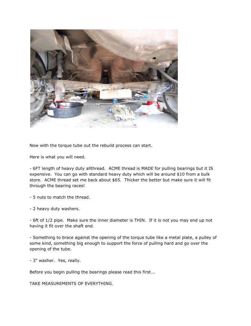
Now with the torque tube out the rebuild process can start.
Here is what you will need.
- 6FT length of heavy duty allthread. ACME thread is MADE for pulling bearings but it IS
expensive. You can go with standard heavy duty which will be around $10 from a bulk
store. ACME thread set me back about $65. Thicker the better but make sure it will fit
through the bearing races!
- 5 nuts to match the thread.
- 2 heavy duty washers.
- 6ft of 1/2 pipe. Make sure the inner diameter is THIN. If it is not you may end up not
having it fit over the shaft end.
- Something to brace against the opening of the torque tube like a metal plate, a pulley of
some kind, something big enough to support the force of pulling hard and go over the
opening of the tube.
- 3" washer. Yes, really.
Before you begin pulling the bearings please read this first...
TAKE MEASUREMENTS OF EVERYTHING.

How deep does the first bearing insert go into the tube? How deep does the opposite end
bearing go in the other end?
How far does the end shaft protrude? These MUST be precise or it WILL NOT go in correctly
and fit into the pilot bearing or worse case you won't be able to bolt the coupler up to the
splines when you put the tranny back in. THIS IS CRUCIAL.
NOW.
Here is how to assemble this. First off, on each end would be 2 nuts, you will double nut
them (tighten them) together so they do not move. The 3 inch washer at the end is
basically just small enough to fit inside the tube, and is big enough to sit flush with the
inserts to pull them out. I do not recommend using a small socket as you MIGHT pull the
bearings out of the inserts and then they get stuck. A huge heavy duty thick 3" washer is
perfect. If you fear it is the wrong size take a measurement and go find one that is close.
The big plate near the mid/end is what will sit up against the mouth of the torque tube and
the nut will sit just past it held in place by a wrench while you spin the end nuts with a
wrench. This in essence will pull the allthread towards you, and the bearings with it, till
they are out of the tube.

First thing first. That shaft HAS to come out.
Using the 1/2" steel pipe, you will fit one end over the pilot shaft end. Make sure it is NOT
reinforced steel or heavy duty steel. STANDARD steel pipe, you do NOT want to damage
your shaft. I hold no responsibility for this. Understand that hammering metal to metal of
any kind could incur damaging. So this rebuild is at your own risk. That said, it /shouldn't
damage it./ but you will use a big hammer or mallet and the pipe to drive the shaft out the
other end.


Now with the shaft out the next thing is to get the bearings out.

Here's the pain in the butt part. The inserts are rubber, so they are fairly difficult to get
out. In this tutorial I am going to go through this in order assuming everything is to be
replaced. So in this case, mix up a nice coating of dish soap (same stuff you'd use to clean
your dishes, yes) and water. What you are going to do is pour this DOWN the torque tube.
Do this a few times so that it's nice and wet and soapy in there.
With your all-thread, assemble and thread it through as described. And you should look like
this.
(please note in this picture i used a socket, DO NOT DO THIS, USE the 3" washer, this was
an early picture before I mangled my inserts from popping a bearing out)

This is how the wrench will be positioned and held still. I used 4x4 wood blocks to space
the pulley out from the tube so the bearings had room to pop out when they came out.
Before you begin spinning them out make sure you coat your allthread with some sort of
lube, I used wheel bearing grease. This is an EXCELLENT lubrication.
Here is what happens if you don't.
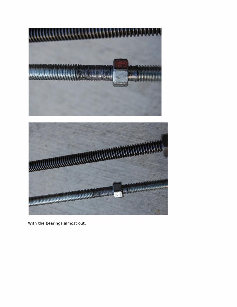
With the bearings almost out.

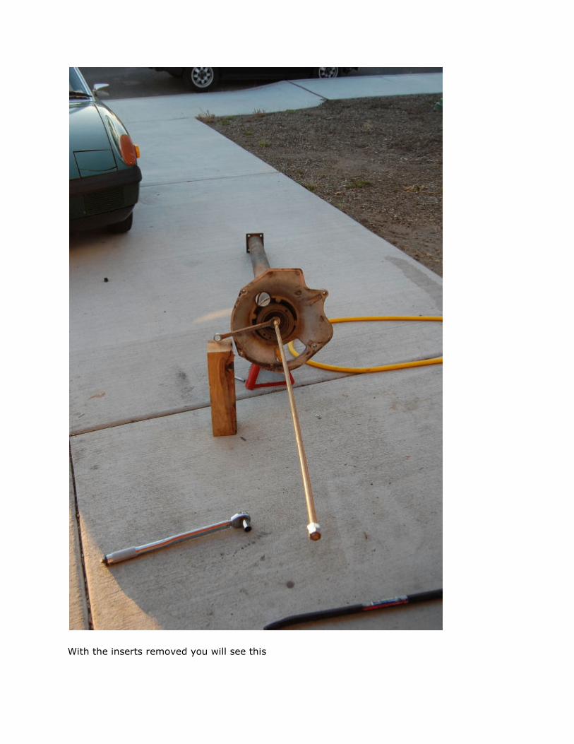
With the inserts removed you will see this

With the tube empty you have a couple options. You can get soapy water and rinse and
wash the poo out of it. Or if you have a buddy with a chimney brush you can brush the
tube with cleaner as well to get any crap out of the tube. I do recommend at least using
some soapy water and washing and rinsing the inside and letting it sit overnight to dry.
Once the tube is clean you will need to prepare the inserts. You should NOT have any
bends, creases or issues with the inserts. If you do GET NEW INSERTS because they may
not lay evenly when you reinstall them.
From here on out you can use a big socket to punch or hammer the old bearings out of the
inserts. DO NOT damage the inserts. But don't worry about the bearings since you will not
reuse them.
I used clarks-garage for the measurements of making the inner races for the new bearings.
You could re-use the old ones but the chances are is that they are old, cracking, worn and
probably not worth re-using.
I had a hell of a time finding the derlin that was described in the tutorial from clarks-garage.
Instead we used the same plastic that is used for wear plates in mills. This is the same
consistency as derlin but is actually water proof, and just as hard. The nice thing about this
is that they don't absorb water the slightest. They will fit somewhat easily over the shaft
once you get them made at the same specification. But once you get them pressed in at a
machine shop to the bearings they will fit more tightly over the shaft which is normal. You
do not want them to be insanely difficult to fit to the shaft but do not want them to be so

loose that it just slides back and forth. You should be able to fit them onto the shaft and
rotate the shaft and the bearing should spin. If it does, then you've got it.
With these inner liners made you will now need to get everything put together. With new
bearings in hand and the new inner sleeves bring your rubber inserts, bearings and sleeves
to a machine shop to have them pressed in.
You should have the following when it's all done.
Now we need to get the inserts back into the tube. Do NOT use the soapy water technique,
you don't water in the tube. Make sure it is entirely dry inside before beginning. Using the
same exact technique you are going to pull the bearings into the tube one at a time. Now,

the important thing to keep in mind here is to measure out an even length between the
bearing. I calculated my torque tube to be approximately 66 or so inches long. My first
bearing was roughly 3 inches in, so I deducted that, then calculated how far the other
bearing went in and deducted that. I then divided the lengths so that I could determine
how many inches between each bearing would equal an EVEN spacing between each one. I
believe it came out to 16.5 inches or 17 inches inbetween. Your tube may have different
depths where the bearings sat. So be sure to measure them and make sure they are evenly
spaced at the right depths.
Pull them back in one at a time (and yes, I realize this is boring and takes forever).
Your next step is to get the shaft back into the torque tube. I did not actually use the same
steel pipe I did last time. Instead, I used a soft heavy hammer made out of brass to
hammer the flat side of the shaft back into the tube.

The reason for this is that you will not damage the shaft or mushroom it with brass. You
also should NOT have to hammer hard, just light taps to get it in. Note the end of the shaft
where you can see the discoloration from the brass hammer.

Again, time to measure. Do not go too far. But it is better to accidentally have the flat part
of the shaft protrude a little extra than have the pilot bearing end too far. Reason for this is

that if it doesn't go far enough you can at least hammer the flat part of the shaft back into
the tube to match the pilot bearing when it is time to reinstall. You CANNOT do that to the
pilot bearing end without taking the tube back out. Keep this in mind.
You should end up with this when you are done.
Now that we've got everything rebuild we need to reverse our process.
Put the torque tube back in over the suspension and where it was sitting next to the
bellhousing. Raise the suspension back up. This is important, use the top torsion bolts
FIRST, THEN the 2 bolts on each side that hold it to the frame and THEN the 2 big bolts or it

will not line up!
Re-torque the suspension bolts and slide and support the torque tube as before.
Re-attach brake lines
Re-attach the plate that supports the TT.
Recap:
- Torque tube is rebuilt and reinstalled and ready to be mated.
- Suspension is back in
- Brake lines attached!
- Plate reinstalled!
Now the part of re-attaching the torque tube. Go ahead and mate it up back to the
bellhousing. Here is one important thing to remember... do NOT let the end of the shaft pry
or bend. You COULD snap it. Though it is unlikely, it is better to be safe than sorry. The
way i did it was to jack the oil pan back up to support the engine and let the torque tube
rest on the suspension then slide it back into the guide tube. Keep in mind it may only go
so far, mine went all the way down to about just a little under 1/4". The reason being is the
pilot bearing. At this point a neat trick is to make sure the torque tube and the bellhousing
are even (one is not pointed up further than the other) and then install the bellhousing bolts
that hold the TT and SLOWLY tighten them in an even amount each one so it goes in flush.
Ensure nothing is bending while it is doing this and make sure again that things are level
with each other.
If you can use this technique it should mate the shaft to the pilot bearing. Once the torque
tube is mated to the bellhousing double check the end of the shaft on the tranny end to
make sure the shaft didn't get pushed. If it did you will need to re-measure the shaft and
use the soft brass hammer to knock it back in to the length it needs to go. Again BE VERY
CAREFUL TAKE YOUR TIME as you do not want to go TOO Far as you will not be able to
mate the coupler to the tranny if you do and you get to take it out and do it all over again.
One the two are back together at the right lengths it will be important to support the tranny
again and evenly jack it up to level with the torque tube and then you can bolt them back
together.
I found it easiest to get the transmission raised to the level of the TT to get the guide tube
for the shift linkage mated first, then threaded the top bolts in to hold it even so I could
move my jack forward and finish the bottom bolts, this worked best for me.
You will then need to hook up the wires (don't forget those!) on your tranny. Install your cv
joints and torque them down.
Once they are torqued down you can use them to turn the transmission again so you can

line the bolts up to mate the coupler to the shafts. You will need to fiddle with it a little to
get the splines lined up. Make sure the bolts are nice and snug.
Once the coupler is mated to the splines, the tranny should be bolted up, cvs in place, you
should now be able to RAISE the transmission up (this will raise the engine and torque tube
up with it) into the mounting brackets and tighten them down. Everything should now be
"back in place."
I did my shift linkage one of the last because it was easiest to leave it loose so I could move
things around. I then came in from the top to slide it back into place and put the bolt back
on to hold it to the linkage on the tranny. KEEP IN MIND TO PUT THE SAFETY WIRE BACK
IN IT! If you don't and that bolt comes up you may end up regretting it when you can't find
out why your car won't shift later on.
Install your shifter back into place.
Quick recap:
- TT installed.
- Tranny mated
- Wires connected to tranny
- CV joints reinstalled
- Brake lines reinstalled
- Don't forget your fuel lines and filter if you disconnected these (optional)
- Tranny installed
At this point you can start installing the exhaust sytem. This will include the heat shield
first. The four 13mm nuts, and then the 2 small screws. Then put the hangars at the end
of the shield (up near the tranny end) and the other hangar inbetween the other end of the
hangar (Up by the engine) but inbetween where there is room on each side. If you get
confused or can't figure that part out, take a measurement of where the hangars are at on
the exhaust and measure from one end to the other on the shield so you put them back in
the right place.
When you torque them down do not bend the hangars, just get them snug so you can tell
they aren't going anywhere.
Install the exhaust starting on the 2 middle hangars. Then get the bolts started for the
rear, DO NOT tighten all the way, just start them so they won't go anywhere.
Now install the exhaust up to the headers. You can re-use the old seals if necessary (I did
with no issues) but be sure to get NEW BOLTS AND NUTS and use a high grade metal do
not go with crappy low grades as they WILL snap over time from heat and stress. Evenly
torque them down on each side till they are nice and snug.
Once the exhaust is installed up to the headers finish installing the bolts on the rear up near

the muffler. Recheck all bolts and nuts to make sure the exhaust isn't going anywhere.
Quick recap:
- Hangars reinstalled, center first!
- Don't fully tighten hangars at rear
- Install header to exhaust, evenly tightening bolts
- No cheap crap!
- Install rear bolts
- Double check bolts for no loose surprises
With the exhaust back together you need to make sure you did not miss anything. Now is a
good time to double check the reference and speed sensors, all your ground straps and
wires as they are crucial to the well being of your car. Double check your suspension bolts.
Make sure nothing is missing. Check your tranny bolts. Do a quick run through and check
off and write all of the major stuff down so you don't forget.
If all is in order you can now install the slave cylinder back in. IT WILL have some pressure
with the new clutch. So you may have to install it by threading the bolts and getting them
started and then slowly tightening them up till it's nice and snut. Also install the starter.
Make sure to bleed your brakes. Don't forget this! It's easy to get in a hurry and be so
close and excited to finished. But make sure you do it! Also check your pedal for pressure,
if air got in during your brake disconnect you need to rebleed your entire system to be safe.
IN fact, I would recommend it. May as well since it's all in pieces!
Once your brakes are bled and the starter and slave are reconnected you now need to
adjust your pedal for free play. You do not want too much freeplay and you don't want too
little. My rule of thumb is to simply take the adjuster and back it off on the pedal till I can
take the pedal with my hand and barely push it and feel the rod hit the plunger. I then will
adjust it just a little bit further till the gap is fairly small. Once I have done this I tighten it
down. This ensures that the pedal is not putting any pressure on the master cylinder and
slave cylinder, allowing the throwout bearing and pressure plate to do their job PROPERLY.
If you do have pressure on it then it may partially be disengaged or slipping, creating heat,
and you may end up back down there before you know it. Or worse, end up ruining your
throwout bearing.
Adjust the freeplay till you are satisfied and tighten down the locking nut for it. Get in the
car and test it out with your foot to make sure you FEEL the small gap for freeplay and the
full disengaged feeling as well. Make sure you can switch gears as you intend and that it is
working properly. If it is, GOOD JOB!
The final part here is to hook up all your cables and lines and go through everything ONE
more time. Yes... I do recommend it. Look at your checklist one more time. Here is a
quick checklist that you can copy paste and print off.

- Brake lines bled
- Suspension is attached correctly
- I made sure all my flywheel bolts and pressure plate bolts were torqued down right when I
did them
- The torque tube mated correctly to the tranny
- The starter and slave are back in, and my pedal is adjusted properly
- All of my ground straps are connected, and all bolts that deal with grounds or connections
got bolted back in
- All extra straps are bolted back in
- My shift linkage is bolted in and I did not forget the safety wire because I am that cool.
- My exhaust hangars were fine and I bolted up the exhaust to the headers properly
- I did remember to lubricate the splines and guide tube before installing the torque tube
- The speed and reference sensors were cleaned off and reinstalled (or replaced and
installed)
- All bolts on the bellhousing were torqued down right.
- I prayed to the Porsche gods not to curse me.
If the checklist checks off and all is well, then you just need to hook up your battery cables,
start her up and give it a go. Remember to be nice to your clutch for a few hundred miles
and try not to slip it as much as you normally would so that the material gets to mate to the
flywheel and break-in.
PART RESOURCES:
Clutch kit
CALL IAN AND THE GUYS!
944online.com
1800944stuf
Torque Tube Bearing Puller
3/4" allthread 6ft long, 5 nuts, one washer 3" in length to fit in torque tube (should basically
be the same size as one of the TT inserts), 2 smaller 3/4" washers (one bigger and one
smaller to fit on 3" washer), one more medium washer to fit behind a nut for your plate or
pulley you will use as a puller.
For the all-thread a normal allthread will do, if you feel like spending the money on "the
good stuff" ask for an "ACME THREAD".
Newhouse Manufacturing Co Inc
Redmond, OR 97756
5415481055
DO NOT CALL THEM for advice on the bearing pulling, they wanted to make it very clear to
me that they are happy to sell the parts necessary but they are VERY busy and did not help
me with the pulling job for the tube, they simply sold me the parts.
If you have any questions you can reply to this thread or email me [email protected] -
happy to help.
Comments/Questions:
on Nov 16th, 2010, 4:37pm, Redbarn wrote: Thank you very much Derek, I am in the middle of rebuilding my engine, flywheel/clutch. torque tube, trans, suspension etc. This is very helpful, great job.
I haven't replaced my rear main seal yet, I have conflicting info from Haynes and other internet sources about weather it should be flush mounted with the block or pushed home as far as it can go, I see you have recessed about 1-2mm, is that as far as it can get seated?
Thanks again. Rob
I was told that if it is recessed to the 1-2mm mark it is as far as it will go. I was told by multiple people that it should go as far as it should go (recessed about 1-2mm) i went that
far and it would go no further. I did not stress it hard, just kept tapping till it felt like it just wouldn't keep recessing. If you look very carefully at the picture with the old seal, it is recessed just as far, although hard to see due to it being so dirty.
on Nov 16th, 2010, 4:56pm, Ronin-951 wrote:
Nice job 'Corsepervita', and a beautiful concise write-up. Dont know how you kept your emotions out of the mix, but thanks for the cencorship.[doesnt really help-physically] Wondering what other 'nice-to-have' tools you would add? Ya, the trany jack and electric impact gun are there, but not a vice or grinder with wire wheel. As many times as you were under and out, did you use a creeper or cardboard[+1]? Anyway, time now to enjoy the fruit of your labor, and a BIG THANKS for sharing.
Yeah I know I can tend to go into story mode but tried to keep it out much as possible. I do tend to write books, but in the instance of a write-up, especially a long one... I can say from doing it I would rather have how to do it and the nitty gritty with the tricks and tips on how
to do it than listen to story time lol. Thanks for the feedback, that is good to hear. I did not use a creeper or cardboard, I just slid on my back. However, my garage floor is very smooth, so it's not a big issue. I did use an old pillow when taking out the tranny
because of how heavy it was. Although if you can get the car high enough, a creeper would probably help! Most my cars are preeeeeettttyyyy low. So I usually don't bother.
I did not end up using anything like a grinder or a vice. If I had to choose, I would most definitely say a professional grade slide hammer would have been awesome for the pilot bearing as it was a real pain in the rear. The one I made worked fine, but the job would have gone faster with a slidehammer with an adapter. The grease pressure trick did me NO
good as it was REALLY in there (obviously, as you can see, there was rust). on Nov 16th, 2010, 7:42pm, vexnoob wrote:
Great write-up.
I'm going to use this when I do my clutch. Probably going to replace the bearings in my torque tube. Now that I understand how to do it better.
Thanks for taking the time man you've made a lot of people's life much easier when the time comes.
I can only thank you guys back! I was definitely new to the 944 when I came here, not as

much to the 924. However, without the help of this community I wouldn't have found the
resources or info I needed to dive so far into my 944. I am happy that I can help others as
they have helped me! That is what I love so much about this place!