The Cosmic Web Imager : An integral field spectrograph for the Hale Telescope at Palomar
12
The Cosmic Web Imager : An integral field spectrograph for the Hale Telescope at Palomar Observatory. Instrument design and first results. Mateusz Matuszewski a , Daphne Chang a , Robert M. Crabill a , D. Christopher Martin a , Anna M. Moore b , Patrick Morrissey a and Shahinur Rahman a a Space Astrophysics Laboratory, Caltech MC 208-17, Pasadena, CA 91125 b Caltech Optical Observatories, Caltech MC 11-17, Pasadena, CA 91125 ABSTRACT We describe the Cosmic Web Imager (CWI), a UV-VIS integral field spectrograph designed for the Hale 200” telescope at the Palomar Observatory. CWI has been built specifically for the observation of diffuse radiation. The instrument field of view is 60”×40” with spectral resolving power of R∼5000 and seeing limited spatial resolution. It utilizes volume phase holographic gratings and is intended to cover the spectral range 3800 ˚ A to 9500 ˚ A with an instantaneous bandwidth of ∼450 ˚ A. CWI saw first light in July 2009, and conducted its first successful scientific observations in May 2010. Keywords: Cosmology, Integral Field Spectroscopy, VPH Gratings, Cosmic Web Imager 1. THE COSMIC WEB IMAGER INSTRUMENT 1.1. CWI Mission The Cosmic Web Imager’s primary objective is to use line emision from hydrogen (Lyα 1216 ˚ A), carbon (CIV 1550 ˚ A), and oxygen (OVI 1036 ˚ A) to detect and map diffuse gas around and between galaxies and quasars at redshifts 2 <z< 6. Measuring the strength, and mapping the extent, of this emission will give a better understanding of the interactions between forming and evolving galaxies and their surroundings. It will help clarify the origin and nature of the Lyman-α blobs already observed using narrowband imaging 1 and lower resolution spectroscopy. 2, 3 This mapping can also reveal the dim filamentary and sheet structure permeating the universe, the so-called cosmic web, which has not yet been directly observed. 4, 5 The CWI combination of ample field of view, moderate resolution, coupled with a relatively high throughput and good noise and background subtraction characteristics, also make the instrument very suitable for studying other diffuse objects, such as light echoes from supernovae, star-forming regions in low surface brightness galaxies, post-merger tidal tails, or superwinds in nearby galaxies, just to name a few. 1.2. CWI Characteristics The Cosmic Web Imager is a UV-VIS integral field spectrograph mounted at the Cassegrain focus of the Hale 200” telescope at the Palomar Observatory. The field of view is 60”×40”; this is well suited to volumes around galaxies and is commensurate with what the characteristic sizes of the Lyα blobs. The instrument spatial resolution is seeing limited (∼1”)in the short direction (along the slices), and slit limited (∼2.5”) in the long direction (across the slices). As the field of view can be rotated on the sky, it is possible to construct a seeing-limited image using multiple exposures covering the same objects at different instrument orientations. CWI has an anticipated wavelength coverage from 3800 ˚ A to 9500 ˚ A with resolving power R = λ/Δλ ≥ 5000 (Δv ≤ 60km/s). At the time Further author information: (Send correspondence to M.M.) M.M.: [email protected], Tel.: (626) 395 1879 D.C.M.: [email protected] P.M.: [email protected] A.M.M.: [email protected] S.R.: [email protected]
Transcript of The Cosmic Web Imager : An integral field spectrograph for the Hale Telescope at Palomar

The Cosmic Web Imager : An integral field spectrograph forthe Hale Telescope at Palomar Observatory. Instrument
design and first results.
Mateusz Matuszewskia, Daphne Changa, Robert M. Crabilla, D. Christopher Martina, AnnaM. Mooreb, Patrick Morrisseya and Shahinur Rahmana
aSpace Astrophysics Laboratory, Caltech MC 208-17, Pasadena, CA 91125bCaltech Optical Observatories, Caltech MC 11-17, Pasadena, CA 91125
ABSTRACT
We describe the Cosmic Web Imager (CWI), a UV-VIS integral field spectrograph designed for the Hale 200”telescope at the Palomar Observatory. CWI has been built specifically for the observation of diffuse radiation.The instrument field of view is 60”×40” with spectral resolving power of R∼5000 and seeing limited spatialresolution. It utilizes volume phase holographic gratings and is intended to cover the spectral range 3800A to9500A with an instantaneous bandwidth of ∼450A. CWI saw first light in July 2009, and conducted its firstsuccessful scientific observations in May 2010.
Keywords: Cosmology, Integral Field Spectroscopy, VPH Gratings, Cosmic Web Imager
1. THE COSMIC WEB IMAGER INSTRUMENT
1.1. CWI Mission
The Cosmic Web Imager’s primary objective is to use line emision from hydrogen (Lyα 1216A), carbon (CIV1550A), and oxygen (OVI 1036A) to detect and map diffuse gas around and between galaxies and quasars atredshifts 2 < z < 6. Measuring the strength, and mapping the extent, of this emission will give a betterunderstanding of the interactions between forming and evolving galaxies and their surroundings. It will helpclarify the origin and nature of the Lyman-α blobs already observed using narrowband imaging1 and lowerresolution spectroscopy.2, 3 This mapping can also reveal the dim filamentary and sheet structure permeating theuniverse, the so-called cosmic web, which has not yet been directly observed.4, 5 The CWI combination of amplefield of view, moderate resolution, coupled with a relatively high throughput and good noise and backgroundsubtraction characteristics, also make the instrument very suitable for studying other diffuse objects, such aslight echoes from supernovae, star-forming regions in low surface brightness galaxies, post-merger tidal tails, orsuperwinds in nearby galaxies, just to name a few.
1.2. CWI Characteristics
The Cosmic Web Imager is a UV-VIS integral field spectrograph mounted at the Cassegrain focus of the Hale 200”telescope at the Palomar Observatory. The field of view is 60”×40”; this is well suited to volumes around galaxiesand is commensurate with what the characteristic sizes of the Lyα blobs. The instrument spatial resolution isseeing limited (∼1”)in the short direction (along the slices), and slit limited (∼2.5”) in the long direction (acrossthe slices). As the field of view can be rotated on the sky, it is possible to construct a seeing-limited imageusing multiple exposures covering the same objects at different instrument orientations. CWI has an anticipatedwavelength coverage from 3800A to 9500A with resolving power R = λ/∆λ ≥ 5000 (∆v ≤ 60km/s). At the time
Further author information: (Send correspondence to M.M.)M.M.: [email protected], Tel.: (626) 395 1879D.C.M.: [email protected].: [email protected].: [email protected].: [email protected]
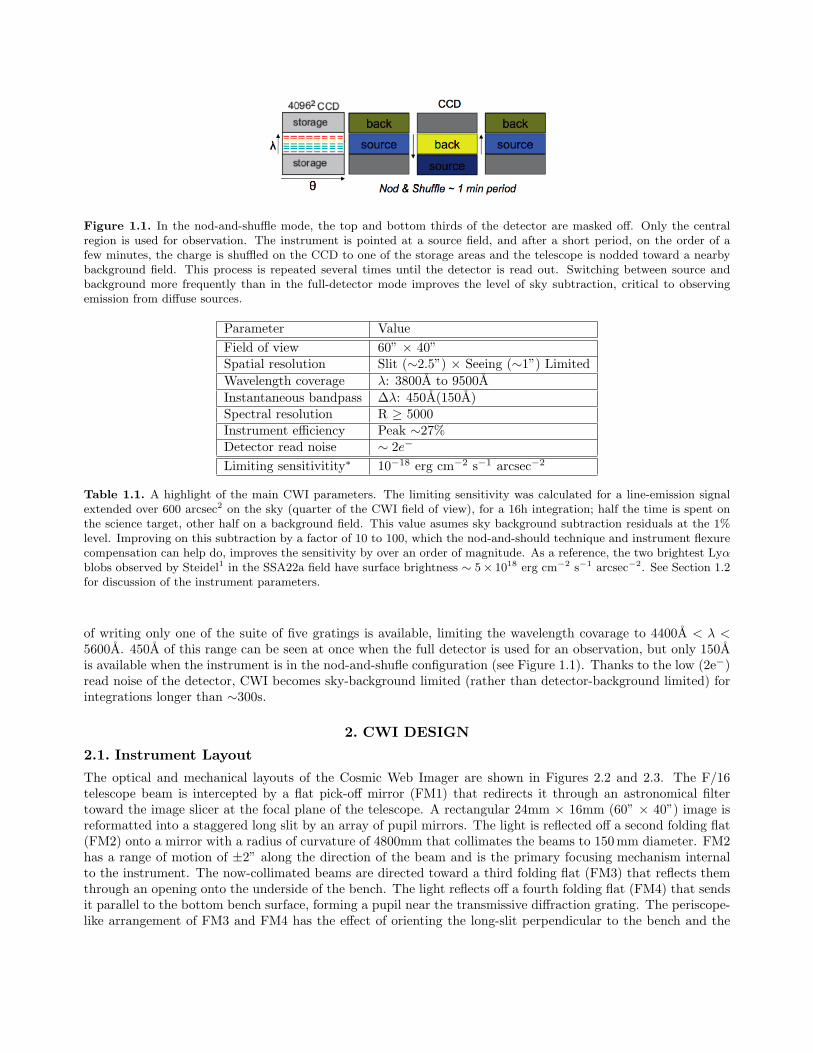
Figure 1.1. In the nod-and-shuffle mode, the top and bottom thirds of the detector are masked off. Only the centralregion is used for observation. The instrument is pointed at a source field, and after a short period, on the order of afew minutes, the charge is shuffled on the CCD to one of the storage areas and the telescope is nodded toward a nearbybackground field. This process is repeated several times until the detector is read out. Switching between source andbackground more frequently than in the full-detector mode improves the level of sky subtraction, critical to observingemission from diffuse sources.
Parameter ValueField of view 60” × 40”Spatial resolution Slit (∼2.5”) × Seeing (∼1”) LimitedWavelength coverage λ: 3800A to 9500AInstantaneous bandpass ∆λ: 450A(150A)Spectral resolution R ≥ 5000Instrument efficiency Peak ∼27%Detector read noise ∼ 2e−
Limiting sensitivitity∗ 10−18 erg cm−2 s−1 arcsec−2
Table 1.1. A highlight of the main CWI parameters. The limiting sensitivity was calculated for a line-emission signalextended over 600 arcsec2 on the sky (quarter of the CWI field of view), for a 16h integration; half the time is spent onthe science target, other half on a background field. This value asumes sky background subtraction residuals at the 1%level. Improving on this subtraction by a factor of 10 to 100, which the nod-and-should technique and instrument flexurecompensation can help do, improves the sensitivity by over an order of magnitude. As a reference, the two brightest Lyαblobs observed by Steidel1 in the SSA22a field have surface brightness ∼ 5× 10¹⁸ erg cm−2 s−1 arcsec−2. See Section 1.2for discussion of the instrument parameters.
of writing only one of the suite of five gratings is available, limiting the wavelength covarage to 4400A < λ <5600A. 450A of this range can be seen at once when the full detector is used for an observation, but only 150Ais available when the instrument is in the nod-and-shufle configuration (see Figure 1.1). Thanks to the low (2e−)read noise of the detector, CWI becomes sky-background limited (rather than detector-background limited) forintegrations longer than ∼300s.
2. CWI DESIGN
2.1. Instrument Layout
The optical and mechanical layouts of the Cosmic Web Imager are shown in Figures 2.2 and 2.3. The F/16telescope beam is intercepted by a flat pick-off mirror (FM1) that redirects it through an astronomical filtertoward the image slicer at the focal plane of the telescope. A rectangular 24mm × 16mm (60” × 40”) image isreformatted into a staggered long slit by an array of pupil mirrors. The light is reflected off a second folding flat(FM2) onto a mirror with a radius of curvature of 4800mm that collimates the beams to 150 mm diameter. FM2has a range of motion of ±2” along the direction of the beam and is the primary focusing mechanism internalto the instrument. The now-collimated beams are directed toward a third folding flat (FM3) that reflects themthrough an opening onto the underside of the bench. The light reflects off a fourth folding flat (FM4) that sendsit parallel to the bottom bench surface, forming a pupil near the transmissive diffraction grating. The periscope-like arrangement of FM3 and FM4 has the effect of orienting the long-slit perpendicular to the bench and the

Figure 2.2. A schematic view of the CWI optical path. See Section 2.1 for more details.
dispersion direction parallel to it. An actuated tilt mechanism in FM3 and FM4 can be used to counteract theeffects of flexure within the instrument. The VPH grating, operating near the Bragg condition disperses thebeams toward the legacy Norris lens. The high performance optic focuses the spectra onto a low noise E2V231-84 CCD. The grating and camera-dewar assembly are mounted so as to be able to rotate about a commonpivot point at the center of the grating, allowing for the selection of the wavelength range to be observed. FM1can be moved out of the way to let a beam from a telescope simulating calibration unit to enter the spectrograph.Additionally, a pair of pick-off flats offset from the main telescope axis sends a (roughly) 3’×3’ portion of thefocal plane of the telescope to a guider camera.
2.2. Integral Field UnitThe CWI Integral Field Unit consists of an image slicer, made of 24 1mm thick, 16mm wide individuallymanufactured aluminum blocks and an array of 24 pupil mirrors (12 each of 21×32 mm2 and 23×36 mm2). Theslicers were designed at Caltech, manufactured and assembled by the Kugler Corporation. The front surfaceof each element is flat and has been machined to a specific tip-tilt compound angle, to an 0.1◦ tolerance. Theoptical surfaces were diamond-turned to a surface roughness of under 7nm rms and given an enhanced aluminumreflection coating. The telescope beam comes to a focus at the slicer and the 60”×40” field of view is redirectedonto the brickwall configuration array of pupil mirrors. These elements reimage the rectangular field of view intoa 465mm long staggered virtual slit that has a slight upward curvature (see Figure 2.4). Each pupil mirror isattached to a solid aluminum backplate via a specially designed flexure mount. The entire IFU is tilted at 10◦
with respect to the bench to reduce vignetting and allow for improved baffling. The IFU was aligned relying onmechanical tolerances and using the tip-tilt pupil mounts to correct the locations of the slices on the detector,removing any overlaps.
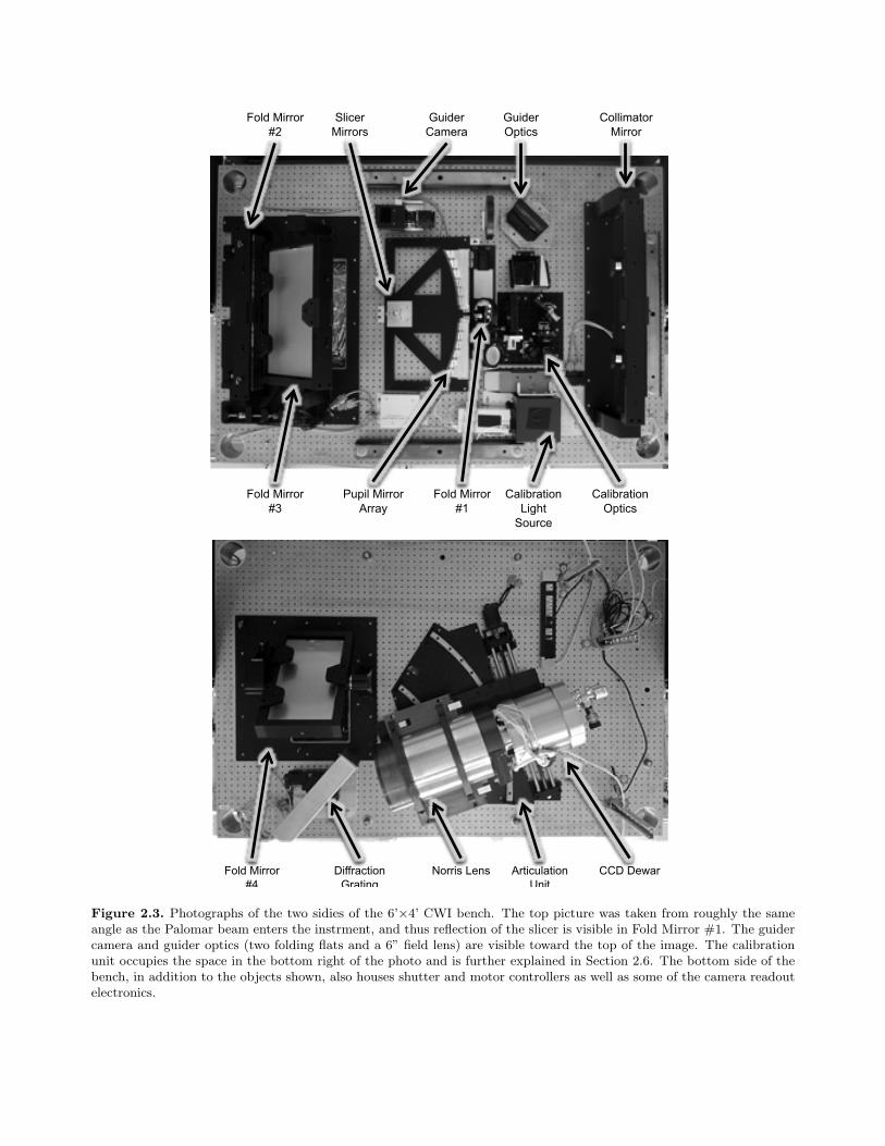
Guider Optics
Guider Camera
Fold Mirror #1
Pupil Mirror Array
Fold Mirror #3
Fold Mirror #2
Collimator Mirror
Slicer Mirrors
Calibration Light
Source
Calibration Optics
Fold Mirror #4
Diffraction Grating
Norris Lens CCD Dewar Articulation Unit
Figure 2.3. Photographs of the two sidies of the 6’×4’ CWI bench. The top picture was taken from roughly the sameangle as the Palomar beam enters the instrment, and thus reflection of the slicer is visible in Fold Mirror #1. The guidercamera and guider optics (two folding flats and a 6” field lens) are visible toward the top of the image. The calibrationunit occupies the space in the bottom right of the photo and is further explained in Section 2.6. The bottom side of thebench, in addition to the objects shown, also houses shutter and motor controllers as well as some of the camera readoutelectronics.

(a)
(c) (d)
(b)
Figure 2.4. The CWI IFU. The slicer stack assembly is shown in figure (a). The slicer mirrors reflect parts of thetelescope focal plane toward the pupil mirror array, shown in (b). The pupil mirror centers lie on a hyperboloid surfaceand are angled so that the images of the slicer mirrors form a virtual slit at the focus of the collimator mirror. Thebrickwall configuration of the pupil mirrors permits an efficient packing of the spectra on the CCD. There is a slightupward curvature to the pupil mirror arrangement, when it is looked at face-on. This counteracts the conic diffractionthat occurs at the grating, thus incrasing the total simultaneous wavelength covered by the slices. The resultant 465mmvirtual entrance slit to the spectrograph is shown in (c). Figure (d) is a schematic of a flexure mount used to install thepupil mirrors. The glass was bonded to these aluminum blocks using 3M Scotch-Weld 2216 Epoxy; the grooves visible atthe top served to channel away the excess bonding agent. The tip-tilt is controlled by two 2-80 fine-threaded screws thatset the angle of the flexures. This design gives an angular range of 1.5◦ in both axes with a resolution better than 0.05◦.

Figure 2.5. Sample measured reflectance curves of the CWI mirrors and the Norris Lens throughput, as measured at Cal-tech. Replacing the mirror coatings with robust multi-layer silver coatings6 is one of the anticipated future improvementsto the instrument that could increase the throughput by as much as a factor of 1.5.
2.3. Mirrors and Coatings
The instrument has seven reflective elements, in addition to the two telescope optics. All reflective coatings areprotected aluminum optimized to the 4000A-5000A range, but, due to differences in materials and vendors, theresultant coatings differ slightly. Figure 2.5 shows several measured reflectivity curves for the CWI optics. Thelarge optics, namely FM1, FM2, FM3, FM4, and the Collimator, were manufactured by Optical Mechanics Inc.The all-metal aluminum slicer mirrors were coated by the assembly vendor, and the BK7 pupil mirrors weregiven a protected aluminum coating by Custom Scientific, Inc.
With the exception of FM1, which is a 4” diameter round mirror, the remaining large optics are rectangular,FM2 and the Collimator having significantly high aspect ratios. The mounts for these optics were designed atCaltech in collaboration with Newmark Systems and manufactured by the latter. The mirrors are held semi-kinematically in cells via a system of 6 pivoting rubber pads, each opposite a pivoting hard-stop. Three of theseare on the front surface, two along the long edge of the mirror and one on the short side. The hard pads thatrest on the optical surfaces of the mirrors are flat, with the exception of the collimator pads that were molded tomatch its radius of curvature. The nitrile rubber pads are compressed to provide a total restoring force of 2.5galong each axis. This value was chosen as a compromise between the force necessary to keep the mirrors fixed inthe cells and protect them from damage during transport to and mounting at the telescope, while keeping thestress on the glass low.
2.4. Gratings
CWI is built to employ VPH gratings, although it can accommodate other transmissive or reflective gratingsor even a mirror, which would result in an imaging mode. The instrument uses the gratings in the classicalBragg condition configuration, as described in literature.7–9 This arrangement permits tuning the instantanousbandpass to any 450A of the wavelengths accessible to a given grating (if the full detector is used; 150A inthe nod-and-shuffle configuration). At the time of writing, CWI is equipped with a single grating manufacturedby Wasatch Photonics covering the wavelength range from 4400Ato 5600A and designed to have its absolutediffraction efficiency maximum at 4900A. The 3050 lines/mm transmission grating, in conjunction with the150mm beam size, 1mm slit-width and angles of incidence and diffraction both greater than 45◦, yield a spectralresolution of R ≥ λ/∆λ ≥ 5000 for the entire range of the grating, with linear dispersion ∼ 7.5A/mm. As thespectrograph operates near Bragg, there is only minimal anamorphic magnification. Conical diffraction effectsare partially taken out with the design of the integral field unit. We measured the grating throughput in lab atthe 532nm green laser line and found it to peak at about 70%. Our measurements of the full system throughputboth in lab and on sky are consistent with this value.

Figure 2.6. CWI green (4400A-5600A) grating mounted on a rotating stage via an interface plate that allows for easymanual exchange.
2.5. Camera and Detector
CWI is reusing the Norris Spectrograph lens.11 This optic has good achromatic performance, with a throughputfall-off toward the blue edge of our wavelength range (see Figure 2.5). Bolted onto the back of the lens barrelis a dewar housing a back-illuminated E2V CCD231-84. The 4096x4096 15µm pixel device is driven by anARC Inc. controller and operated using an ArcView and LabView based software suite. The detector runs atT∼-90◦C and exhibits exceptionally low read noise at ∼2e− for all four device read-out channels. The CCD hasan anti-reflection coating that peaks at ∼80% between 4000A and 5000A. A mask assembly can be attached tothe CCD package to block off 2/3 of the device as storage areas for the nod-and-shuffle mode.
2.6. Calibration Unit
The dedicated calibration unit is built to simulate the Hale telescope beam. The design is illustrated in Figure2.9. An LED continuum and ThAr arc lamp feed a 6” calibration sphere. At the exit port of the sphere is alinear stage that places one of several calibration objcts in front of the 1.5” exit port. These include a flat-fieldaperture, a regular pinhole grid of 100µm pinholes on 1mm pitch, and a single 250µm pinhole which can bemoved to any location within the port. A 250mm focal length lens reimages the selected calibration object ontothe slicer. An aperture stop between the calibration objects and the lens is reimaged to form a virtual pupil atthe same distance from the slicer stack as the exit pupil of the telescope. Several folding flats route the beamswithin a compact area of the CWI optical bench. The calibration beam is injected into the instrument by slidingFM1 and replacing it with a pair of flat mirrors in a periscope configurtion.
2.7. Guider Camera
Accurate sky and point source subraction, as well as the nod-and-shuffle observing mode, require that theinstrument pointing be repeatable to under an arc-second. To ensure this CWI is equipped with an opticalguider. A pair of flat mirrors redirect a part of the telescope beam offset by 10 arc-minutes from the Hale opticalaxis and bring it to a focus at a large format field lens. The light is then focused by an off-the shelf consumerlens onto the image-intensified detector of the Shepherd Autoguider.12 (This has been used as the guidancesystem on several Palomar Observatory instruments). The preoptics yield a field of view of 200” × 200”. Thisis sufficiently large to contain a few stars down to 20th magnitude in the V band.
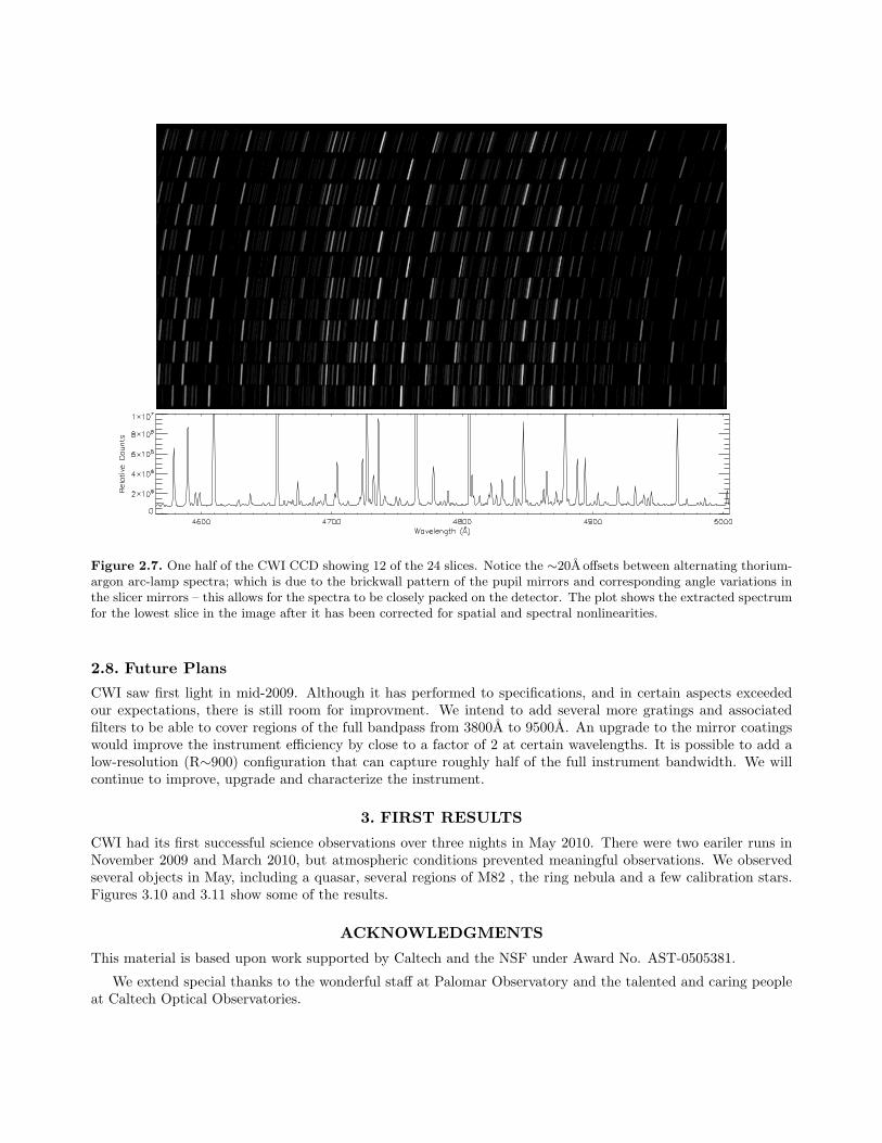
Figure 2.7. One half of the CWI CCD showing 12 of the 24 slices. Notice the ∼20A offsets between alternating thorium-argon arc-lamp spectra; which is due to the brickwall pattern of the pupil mirrors and corresponding angle variations inthe slicer mirrors – this allows for the spectra to be closely packed on the detector. The plot shows the extracted spectrumfor the lowest slice in the image after it has been corrected for spatial and spectral nonlinearities.
2.8. Future Plans
CWI saw first light in mid-2009. Although it has performed to specifications, and in certain aspects exceededour expectations, there is still room for improvment. We intend to add several more gratings and associatedfilters to be able to cover regions of the full bandpass from 3800A to 9500A. An upgrade to the mirror coatingswould improve the instrument efficiency by close to a factor of 2 at certain wavelengths. It is possible to add alow-resolution (R∼900) configuration that can capture roughly half of the full instrument bandwidth. We willcontinue to improve, upgrade and characterize the instrument.
3. FIRST RESULTS
CWI had its first successful science observations over three nights in May 2010. There were two eariler runs inNovember 2009 and March 2010, but atmospheric conditions prevented meaningful observations. We observedseveral objects in May, including a quasar, several regions of M82 , the ring nebula and a few calibration stars.Figures 3.10 and 3.11 show some of the results.
ACKNOWLEDGMENTS
This material is based upon work supported by Caltech and the NSF under Award No. AST-0505381.
We extend special thanks to the wonderful staff at Palomar Observatory and the talented and caring peopleat Caltech Optical Observatories.

Figure 2.8. Typical CWI instrument throughput for a single slice (solid line), including telescope and atmosphericlosses. The curve was obtained from a 30s observation of a calibration standard10 star BD+28 4211. Taking into accounttelescope mirror reflectivity of ∼85% for the two Hale optics and atmospheric extinction A(V ) ∼ 0.3 gives an estimatefor the intrument throughput (dotted line).
DiffuseLight
Source
ImageSlicer
CalibrationObjects
������������������������
������������
ReimagingLens
ApertureStop
����
����
Figure 2.9. CWI Calibration Unit Schematic. An LED continuum source and ThAr line source feed a 6” integratingsphere. Different calibration objects can be placed at the exit port of the sphere. These are then reimaged through anaperture stop and a 250mm focal length lens onto the image slicer.

Figure 3.10. CWI took a 10 minute exposure of M57 (Ring Nebula). The orientation of the IFU is shown on the insetoverlayed over a Hubble image of the object. The spectrum is generated from coadding the data from the full field.Prominent HeII(4685A), Hβ(4863A) and [OIII](4959A) are visible. A zoomed view of a subregion shows a zoo of emissionlines of various elements, including Oxygen, Helium, Carbon, and Neon. Note that CWI is resolving closely spaced lines,verifying R∼5000.

Figure 3.11. A 10 minute exposure of a central region of M82 in both continuum and at Hβ compared with thecorresponding continuum and Hα images from the SINGS13 archive. All images are 60”×40”. Note the morphologicalsimilarities between the two sets of images.

REFERENCES1. C. C. Steidel, K. L. Adelberger, A. E. Shapley, M. Pettini, M. Dickinson, and M. Giavalisco, “Lyα Imaging
of a Proto-Cluster Region at 〈z〉 = 3.09,” Astrophysical Journal 532, pp. 170–182, Mar. 2000.2. R. J. Wilman, J. Gerssen, R. G. Bower, S. L. Morris, R. Bacon, P. T. de Zeeuw, and R. L. Davies, “The
discovery of a galaxy-wide superwind from a young massive galaxy at redshift z ˜ 3,” Nature 436, pp. 227–229, July 2005.
3. A. Weijmans, R. G. Bower, J. E. Geach, A. M. Swinbank, R. J. Wilman, P. T. de Zeeuw, and S. L. Morris,“Dissecting the Lyman α emission halo of LAB1,” MNRAS 402, pp. 2245–2252, Mar. 2010.
4. S. R. Furlanetto, J. Schaye, V. Springel, and L. Hernquist, “Mapping the Cosmic Web with Lyα Emission,”Astrophysical Journal Letters 599, pp. L1–L4, Dec. 2003.
5. C. Faucher-Giguere, A. Lidz, and L. Hernquist, “Numerical Simulations Unravel the Cosmic Web,” Science319, pp. 52–, Jan. 2008.
6. J. Wolfe and D. Sanders, “Optical and environmental performance of durable silver mirror coatings fabri-cated at llnl,” in Optical Interference Coatings, Optical Interference Coatings , p. TuF11, Optical Society ofAmerica, 2004.
7. S. C. Barden, J. B. Williams, J. A. Arns, and W. S. Colburn, “Tunable Gratings: Imaging the Universein 3-D with Volume-Phase Holographic Gratings (Review),” in Imaging the Universe in Three Dimensions,W. van Breugel & J. Bland-Hawthorn, ed., Astronomical Society of the Pacific Conference Series 195,pp. 552–+, 2000.
8. I. K. Baldry, J. Bland-Hawthorn, and J. G. Robertson, “Volume Phase Holographic Gratings: PolarizationProperties and Diffraction Efficiency,” Publ. Astron. Soc. Pac. 116, pp. 403–414, May 2004.
9. R. D. Rallison, R. W. Rallison, and L. D. Dickson, “Fabrication and testing of large area VPH grat-ings,” in Society of Photo-Optical Instrumentation Engineers (SPIE) Conference Series, E. Atad-Ettedgui& S. D’Odorico, ed., Society of Photo-Optical Instrumentation Engineers (SPIE) Conference Series 4842,pp. 10–21, Feb. 2003.
10. J. B. Oke, “Faint spectrophotometric standard stars,” Astronomical Journal 99, pp. 1621–1631, May 1990.11. H. W. Epps, “Camera designs for the Keck Observatory LRIS and HIRES spectrometers,” in Society of
Photo-Optical Instrumentation Engineers (SPIE) Conference Series, D. L. Crawford, ed., Presented at theSociety of Photo-Optical Instrumentation Engineers (SPIE) Conference 1235, pp. 550–561, July 1990.
12. M. Shepherd, “Palomar autoguider.” http://www.astro.caltech.edu/~mcs/autoguider/index.html.13. R. C. Kennicutt, Jr., L. Armus, G. Bendo, D. Calzetti, D. A. Dale, B. T. Draine, C. W. Engelbracht,
K. D. Gordon, A. D. Grauer, G. Helou, D. J. Hollenbach, T. H. Jarrett, L. J. Kewley, C. Leitherer, A. Li,S. Malhotra, M. W. Regan, G. H. Rieke, M. J. Rieke, H. Roussel, J. Smith, M. D. Thornley, and F. Walter,“SINGS: The SIRTF Nearby Galaxies Survey,” Publ. Astron. Soc. Pac. 115, pp. 928–952, Aug. 2003.