The Complete HOBAS Guide · Centrifugally Cast, Fiberglass-Reinforced, Polymer Mortar Pipe The...
76
Centrifugally Cast, Fiberglass-Reinforced, Polymer Mortar Pipe The Complete HOBAS Guide
Transcript of The Complete HOBAS Guide · Centrifugally Cast, Fiberglass-Reinforced, Polymer Mortar Pipe The...

Centrifugally Cast, Fiberglass-Reinforced, Polymer Mortar Pipe
The Complete HOBAS Guide
R15 10/2015

Why Pick HOBAS?
The HOBAS name on the pipe says you’ve chosen the leader in pipe technology: first choice for virtually every application and method of installation:
• Sliplining • Two-Pass Tunneling • Jacking or Microtunneling • Above Ground• Direct Bury
It’s the Best Pipe Investment You Can Make: Centrifugal Casting Is the Difference.

What Do You Want in Your Pipeline? Here’s What HOBAS Delivers:
Easy To Specify, Lower Project Cost, Superior Engineering and Customer Support
HOBAS DefinedHOBAS pipes are unique – centrifugally cast, fiberglass reinforced, polymer mortar (CCFRPM). They are strong and light with consistent dimensions, smooth surfaces and high stiffness.
Longest Service LifeHOBAS pipe is inherently corrosion resistant because of the materials that go into it. Design service life is up to 100 years and more.
Every step of the HOBAS manufacturing process is carefully controlled and verified. In the Quality Control lab, samples taken from the production line are checked for adherence to the standards and specifications.

Table of Contents
2
3
4
5
6
4
7
9
13
15
19
7 21
8 23
1
Section Page
IntroductionProductCompanyExperience
ApplicationsEnvironmentsInstallationsService
Features/Benefits
Product RangeDiametersLengthsStiffness ClassesPressure ClassesFittings
Pipe Stiffness SelectionDirect BurySlipliningJackingAbovegroundTunnel Carrier
Pipe Capabilities & DesignInternal PressureNegative PressureAllowable Cover DepthTraffic LoadsFlotationAbrasion ResistanceDesign
Hydraulics
JointsJoint SelectionFWC CouplingLow Profile Bell-SpigotPressure ReliningFlush Bell-SpigotFlush FWC CouplingClosure CouplingsConnections to Other Pipe Material Systems

Table of Contents
9
A
B
C
D
E
F
G
10
11
12
13
14
29
49
55
57
59
60
64
70
31
33
35
37
39
Fittings
ManholesHOBAS Tee Base SystemConnecting HOBAS Pipe to Concrete Manhole Systems
Pipe Manufacturing Process
Quality Control
Standards
InstallationA - Direct BuryB - SlipliningC - JackingD - AbovegroundE - Tunnel Carrier
AppendixGuide SpecificationsNon-Pressure Service Pressure Service Direct Bury PipesSliplining Pipes Jacking PipesAboveground PipesTunnel Carrier Pipes
Pipe Dimensions & Weights
Joint Dimensions & Weights
Pipe Material Properties and Characteristics
Fitting Dimensions
Corrosion Resistance Guide
Deflected Pipe Minimum Inside Diameters
Section Page

High strength, high stiffness and inherent corrosion resistance make HOBAS pipes ideal for many applications such as this sanitary sewer aerial crossing.
Introduction
1
Intro
du
ction
ManufacturingSophisticated HOBAS manufacturing means you get real value, the lowest life cycle cost in the industry for both new installations and rehabilitation.
ASTMHOBAS meets or exceeds ASTM standards as measured in sewer pipe accelerated aging tests. Results project that HOBAS pipe will last many thousands of years – unequaled by any other pipe needs.
Getting TechnicalIn the most scientific terms, HOBAS pipe is a glass-fiber-reinforced, aggregate-fortified, thermosetting-resin tubular product manufactured by a centrifugal casting process.
Wall Construction: I-Beam Principle
OUTER LAYER (Sand and Resin)
HEAVILY REINFORCED(Chopped Glass and Resin)
TRANSITION (Glass, Resin, Mortar)
CORE (Polymer Mortar)
TRANSITION (Glass, Resin, Mortar)
HEAVILY REINFORCED (Chopped Glass and Resin)
LINER (High Elongation Resin)
4 5

OUTER LAYER (Sand and Resin)
HEAVILY REINFORCED(Chopped Glass and Resin)
TRANSITION (Glass, Resin, Mortar)
CORE (Polymer Mortar)
TRANSITION (Glass, Resin, Mortar)
HEAVILY REINFORCED (Chopped Glass and Resin)
LINER (High Elongation Resin)
Consistent Quality and Performance Most U.S. municipalities have HOBAS pipe in their systems and the use of HOBAS pipe in the USA is expanding faster than ever after more than 25 years of reliable performance. More than 40,000 miles of HOBAS pipe has been installed around the world.
VersatileHOBAS pipes can be economically designed for non-pressure and pressure service by varying the quantity, placement and orientation of the glass-fiber reinforcements.
Smoother Surfaces, High Flow CapacityHOBAS Pipe is manufactured with a unique, precise, computer-controlled, centrifugal casting process that no other method can deliver. This produces very consistent, high-density pipe with a mold-smooth exterior surface and a glass-smooth nonporous liner that is resilient and abrasion resistant. In addition to superior hydraulics, thin-wall construction produces an oversized I.D. for the highest flow capacity available.
Leak-Free Joints Another HOBAS advantage is push-together joints for a leak-free pipeline that preserves the streets above and reduces treatment costs.
Straightforward Installation Installation is quick and easy with predictable, reliable pipe performance by every method. Push-together joints are simple and fast to assemble. Lightweight pipes are safe and easy to handle, often with the smaller equipment typically on the site.
The Product
5

6 7
A Little HistoryIn the mid-fifties, a textile manufacturer, seeking a replacement for the traditional wooden rollers, tried to produce cylinders with a smooth surface using polyester resin reinforced with glass fiber.
They tried the widely used filament winding process, but found that it was unsuitable because the outside surface it produced was not smooth enough. The idea of manufacturing the cylinders by centrifugal casting was born. HOBAS pipe is a direct descendant of that invention.
Shortly after, the first piping application appeared. Engineers needed a durable, corrosion resistant pipe with smooth interior surface. Centrifugal casting was adapted to meet the specifications and production quickly expanded. Soon after, pipes were installed in Europe.
HOBAS Worldwide
Today HOBAS pipe is manufactured and used around the world. From Seattle to Key West, New York to Los Angeles, most U.S. municipalities have HOBAS pipe in their systems. After more than 45 years of reliable service, the use of HOBAS pipe is expanding faster than ever.
Currently, in addition to the USA, HOBAS has factories in Austria, Japan, Germany, China, Thailand, United Arab Emirates, Spain, Poland, Turkey, Uzbekistan, Czech Republic, Kazakhstan, Romania and Egypt. The group of companies has provided more than 40,000 miles of pipe. Over 6.5 million feet have been installed in the USA.
1
Intro
du
ction

7
Applications
2
Ap
plicatio
ns
HOBAS centrifugally cast fiberglass reinforced polymer mortar pipes are ideally suited for nearly all large diameter corrosive piping applications. Listed below are the most common environments, installations and services in which the pipe has been used.
Environments• Gravity sanitary sewers• Sewer force mains• Raw water • Sea water • Industrial effluents• Irrigation• Geo-thermal piping• Wastewater collection systems• Storm water and sewer water segregation systems• Odor control piping• WWTP piping• Potable water• Contaminated water• Cooling water• Foul air
Installation and Service Operation
Note: Products available for sustained temperatures over 150 º F.See Corrosion Resistance Guide in Appendix F.
Installation
Direct • •Bury Relining • •(Sliplining)Jacking & • •MicrotunnelingAbove • •GroundTunnel WaterwayCarrier • •
Pipe Bursting • •
Service OperationNon-Pressure Pressure
Direct bury installation at DFW Airport
84-inch diameter Hydro-Electric Penstock in New Hampshire
Versatile Solution

2
Ap
plicatio
ns
8 9
84-inch diameter jacking pipe for the City of Los Angeles.
30-inch diameter sanitary sewer vent line.
60-inch CMP storm culvert rehabilitation with 54-inch HOBAS.
60-inch diameter, 100 psi sewer force main in a two-pass system.

9
Features/Benefits
3
Features/B
enefi
ts
HOBAS centrifugally cast fiberglass reinforced polymer mortar pipes have many outstanding features that provide numerous cost saving
• Long, maintenance-free service life.
• No costly add-on linings or coatings to damage, repair, inspect or maintain.
• No need for expensive cathodic protection or polybags to install and monitor.
• Ideal pipe for economical relining of corroded pipelines.
• Hydraulic characteristics are virtually unchanged with time.
• Easy to bury using methods routinely specified for traditional pipes.
• Performance is predictable and reliable.
• Deep covers handled with ease.
• Pipes are rugged and durable.
• Easy to grout annulus on sliplining and tunnel lining applications.
Inherent corrosionresistance
High stiffness design
Inherent corrosion resistance of HOBAS pipes is proven by testing in acid under high stress.
benefits. Listed below are some of the key features and resulting benefits.
Better by Design
Features Benefits

10 11
• Deliver more fluid than any corrosion resistant pipe.
• Permits greatest recovery of flow in rehabilitated pipelines.
• Significant energy savings in pumped systems.
• Zero infiltration/exfiltration.
• No extra treatment costs.
• No pollution of ground waters.
• Full delivery of pumped fluids.
• No wasted time & expense trying to find and seal leaking joints to pass acceptance tests.
• No undermining of above structures and infrastructure.
Smooth interiorsurface & oversize ID’s
Bottle-tightjoints
Features Benefits
High stiffness pipes perform reliably even at deep covers such as this installation in Baltimore.
Reflection smooth interior surface and oversize ID’s of HOBAS pipes provide outstanding long-term flow characteristics.
3
Features/B
enefi
ts

11
3
Features/B
enefi
ts
• Lighter, less expensive equipment needed for handling.
• Fewer joints to assemble.
• “Fool-proof,” fast assembly.
• Requires no secondary treatments, diapers, bonding agents or other chemicals in the field.
• Lower joining costs.
• Radius curves possible without the need for fittings.
• Pipe may be cut anywhere along its entire length and assembled with gasketed joints with only end chamfering needed.
• Lower forces required to insert pipe into casings or deteriorated pipelines for rehabilitation.
• Allows longer distance bored tunnels with lower jacking loads, thereby reducing shaft requirements and increasing safety margins.
Lightweight/20 ft. sections
Push-on coupling joints with angular rotation capability
Smooth Constant OD
Features Benefits
Lightweight HOBAS pipes handle easier and lay faster with less expensive equipment.
Smooth, constant OD of HOBAS pipes permits cutting and joining anywhere along its entire length.
HOBAS push-on FWC coupling joints assemble easily and provide leak-free service.
Features Benefits

• Excellent abrasion resistance.
• High crack resistance.
• Consistent, reproducible high quality pipes.
• Multiple pressure & stiffness classes to meet most project requirements.
• OD’s compatible with standard ductile iron fittings.
• Service tested and time proven performance record.
Resilient inner liner
Computer controlled manufacturing process
Standardized designs & dimensions
50 year history ofsuccessful applications
Features Benefits
3
Features/B
enefi
ts
12 13
As you can see, HOBAS fiberglass reinforced polymer mortar pipes save you money during installation and in operation. These initial and daily savings compounded with the elimination of expense for repairs, rehabilitation or premature replacement, make our fiberglass pipes YOUR BEST VALUE IN CORROSION RESISTANT PIPING.
Computer controlled and monitored production results in consistent, high quality HOBAS pipes.

Features Benefits
13
Product Range
4
Pro
du
ct Ran
ge
Note: Actual dimensions are given in Appendix B. Other nominal diameters may be available. Please inquire.
72” 78” 84” 85” 90” 96” 104” 110” 120” 126”
18” 20” 24” 27” 28” 30” 33” 36” 41” 42”
Nominal Diameters
Stiffness Classes (SN)
Standard
Infrequent
Very Unusual
SN is minimum pipe stiffness in psi.
Direct Bury
SlipliningNon Pressure
SlipliningPressure
Pipe Bursting, Jacking& Microtunneling
Tunnel Carrier Pipe
Aboveground See page 17, 46 & 47
SN SN SN SN SN Installation 18 36 46 72 >72
Lengths
Standard 20 foot sections (Special lengths and even divisions of 20 ft. are available.)
Diameter range is 18” to 126”.
Standard section length is 20 ft. although shorter pipes are available.
44” 45” 48” 51” 54” 57” 60” 63” 66” 69”

14 15
4
Pro
du
ct Ran
ge
Pressure Classes
Dia. (in.)PN (psi)
25 50 100 150 200 250
Non-Standard
18 20 24 27 28 30 33 36 41 42 44 45 48 51 54 57 60 63 66 69 72 78 84 85 90 96 104 110 120 126
Fittings
Fiberglass reinforced polymer flanges, elbows, reducers, tees, manholes, wyes & laterals, constructed by contact molding or from mitered sections of fiberglass reinforced polymer mortar pipe joined by glass-fiber-reinforced overlays, are available for all non-pressure and many pressure applications. Protected ductile iron, fusion-bonded epoxy- coated steel or stainless steel fittings are typically compatible and may be used with all HOBAS pressure classes. Fitting details may be found in Section 9 and Appendix E.
Riser pipes are available for both new construction and rehabilitation.
A variety of manhole fittings and options are available to suit your needs.

15
FIGURE 1 - Pipe Stiffness Selection for Standard Installations1
Pipe Stiffness Selection
Direct Bury ApplicationsAppropriate pipe stiffness is a function of native soil characteristics, trench construction, cover depth, embedment conditions, and haunching. Figure 1 (See below) relates these parameters assuming a minimum width trench as defined in Figure 11 (pg. 39). (Under certain circumstances, pipe stiffness less than 36 psi may be suitable.)
For pipes with vacuum operating conditions, see Allowable Negative Pressure in Section 6 (pg. 19) for appropriate pipe stiffness for various installations and negative pressures.
For shallow buried pipes with surface loads, see Traffic Loads in Section 6 (pg. 20) for appropriate pipe stiffness for various installations and cover depths.
HOBAS pipes easily withstand a full vacuum service condition due to the high stiffness design.
High stiffness HOBAS pipes may be buried safely at depths exceeding 50 ft.
5
Pip
e Stiffn
ess
NATIVE SOIL 2, 5 COVER EMBEDMENT CONDITION3
DEPTH1
(ft.) 1 2 3 4
1 Assuming typ. 1.5 x OD Trench Width (or as in Figure 11) 2 Soils adjacent to pipe (pipe zone elevation)3 Defined in Figure 13 4 For zero blow (weight of hammer) soils, use Alternate Installation & SN 725 SN is nominal stiffness in PSI6 Alternate Installation per section 14, A8-Typ. SN 72 min.
10 & <
>10 to 20
>20 to 30
>30 to 40
>40 to 50
>50 to 60
>60 to 70
10 & <
>10 to 20
>20 to 30
>30 to 40
10 & <
>10 to 20
>20 to 30
10 & <
>10 to 20
ROCK
Stiff to V. Hard Cohesive (Qu ≥ 1 Tsf)
Compact to V. Dense Granular (SPT N ≥ 8 bpf)
Medium Cohesive (Qu ≥ 0.5 Tsf)
Loose Granular (SPT N = 4 to 7 bpf)
Soft Cohesive (Qu ≥ 0.25 Tsf)
V. Loose Granular (SPT N = 2 to 3 bpf)
V. Soft Cohesive (Qu ≥ 0.125 Tsf)
V. V. Loose Granular (SPT N ~ 1 bpf)
SN 46
SN 72
SN 36
SN 72
SN 72
SN 46
SN 36
SN 72
SN 72
SN 46SN 72
SN 90
SN 72
SN 120
SN 46
SN5 36SN5 72
SN 72
SN 46
SN 36SN 46SN 72
SN 90SN 120Alternate Installation
STIFFNESS CLASS KEY
ALTERNATE INSTALLATION6
ALTERNATE INSTALLATION6
ALTERNATE INSTALLATION6
ALTERNATE INSTALLATION6

Sliplining Applications
Appropriate pipe stiffness is a function of the insertion compressive load, grouting pres-sure, grouting deformation loads and external hydrostatic head.
• The table below lists safe (F of S ≈ 3) compressive loads for pushing “straight” for various pipe stiffness classes and diameters. When pushing around curves, allowable safe loads will be reduced depending on the curve radius and pipe section length.
• For safe compressive loads when pushing “straight” on pipe with the flush bell-spigot
joint, see the table in the “Tunnel Carrier Pipe Applications” portion of this section on page 18.
• Maximum safe (F of S ≈ 2.0) grouting pressure (psi) without support bracing or counter pressurization is shown in Chart A.
• Net uplift forces (displaced grout weight minus pipe and flow weight) must be coordinated with pipe stiffness to control pipe deformation to within acceptable limits.
• Safe (F of S ≈ 1.5) long-term external hydrostatic head (ft.) for an ungrouted installation is shown in Chart B.
Max. Safe Long-term External Head (ft.) for an Ungrouted Installation
All Flow levels ≤ 5% SN÷2 ≤ 10% SN÷2.5 ≤ 20% SN÷3 > 20% SN÷4
Fluid Flow Level
Dia.Difference
Chart B
Fluid Flow Level
Max. Safe Grouting Pressure (psi)
None over 1/2 or to low full ≤ 5% SN÷4 SN÷3 ≤ 10% SN÷5 SN÷4 ≤ 20% SN÷6 SN÷5 > 20% SN÷7 SN÷6
Chart A
Dia.Difference
Notes:Diameter Difference =
(ID Host Pipe - OD Liner Pipe) X 100 OD Liner Pipe
SN is nominal pipe stiffness in psi
5
Pip
e Stiffn
ess
16 17
Nom. Dia. (in.)
O.D. (in.)
PipeWall Bell
Safe Compressive LoadPushing “Straight” (U.S. Tons)SN 36 SN 46 SN72
18 19.5 20.4 – 25 (SN 62) 27 20 21.6 22.5 – 29 36 24 25.8 26.8 39 44 54 27 28.0 29.0 48 54 66 28 30.0 31.0 56 63 77 30 32.0 33.0 51 58 74 33 34.0 35.0 60 67 85 36 38.3 39.3 82 92 115 41 42.9 44.0 108 122 149 42 44.5 45.6 119 134 162 44 45.9 47.0 128 143 175 45 47.7 48.8 141 159 192 48 50.8 51.9 164 183 220 51 53.9 55.0 188 211 254 54 57.1 58.2 215 239 288 57 60.0 61.2 242 268 322 60 62.9 64.1 271 297 358 63 66.0 67.2 302 333 396 66 69.2 70.4 305 342 412 69 72.5 73.8 339 378 458 72 75.4 76.7 373 417 501 78 81.6 82.9 448 496 595 84 87.0 88.4 520 575 686 85 88.6 90.0 544 601 717 90 94.3 95.7 625 690 820 96 99.5 101.0 702 776 924 104 108.0 109.5 844 930 1101 110 114.0 115.5 950 1050 1240 120 126.0 127.5 1190 1300 1535 126 132.5 134.3 1300 1420 1705
Low-Profile Bell-Spigot Joint Allowable Compressive Load

17
5
Pip
e Stiffn
ess
Note: Alternate pipe designs are available upon request.
Allowable Safe Jacking Load Pushing “Straight”
(U.S. Tons)
F of S = 3.0
Min. Pipe Wall Thickness @
Gasket Groove(in.)
Nom. Dia.(in.)
O.D.(in.)
Nom. InsideDia.(in.)
Min. Pipe Wall
Thickness (in.) F of S = 2.5
Jacking Bell-Spigot Joint Allowable Compressive Load
Weight (lb/ft)
*****
* Lead times may be lengthy, please inquire.
Jacking Applications
Non-PressureAppropriate pipe stiffness is a function of the jacking compressive load and installation conditions. The jacking contractor must control the jacking loads within the safe limits for the pipe. The adjacent table shows allowable safe jacking loads (pushing “straight”) for the typical design. However, the ultimate pipe load capacity is the choice and responsibility of the purchaser and can be affected by a number of factors including the anticipated loads, the amount of
steering, the amount of over-cut, the amount of lubrication, the pipe section length, the distance of the jacking operation and any point loading.
PressureDetails of pressure service jacking pipes are available on a custom design basis depending on jacking loads, operating parameters, and installation conditions.
Aboveground Applications
Appropriate pipe stiffness is a function of the pipe support scheme, pipe diameter, imposed loads and the level of negative operating pressure, if any. Section 14D on above-ground installation provides guidance on pipe support requirements for various pipe classes and diameters. Maximum negative pressure is as given in the adjacent table.
48-inch aerial interceptor at a WWTP in Odessa, TX withstands high temperatures.
HOBAS jacking pipes have the lowest drive loads.
Aboveground Allowable Negative Pressure
Allowable NegativePressure*
(% of full vacuum)
Pipe Stiffness(psi)
18 25 36 50 46 60 72 100* at 75° F.
24 25.8 22.7 1.40 0.99 125 150 107 27 28.0 24.8 1.47 1.06 145 175 120 28 30.0 26.6 1.53 1.12 166 200 137 30 32.0 28.3 1.71 1.21 191 230 159 33 34.0 30.1 1.80 1.29 216 260 179 36 38.3 34.3 1.85 1.31 250 300 208 41 42.9 38.7 1.91 1.32 283 340 245 42 44.5 40.3 1.93 1.33 295 355 255 44 45.9 41.7 1.95 1.34 308 370 263 45 47.7 43.4 1.98 1.35 325 390 280 48 50.8 46.4 2.03 1.37 350 420 306 51 53.9 49.4 2.07 1.38 375 450 333 54 57.1 52.5 2.10 1.39 400 480 361 57 60.0 55.4 2.13 1.40 425 510 380 60 62.9 58.2 2.16 1.41 450 540 408 63 66.0 61.2 2.20 1.42 475 570 438 66 69.2 64.2 2.31 1.43 500 600 478 69 72.5 67.4 2.38 1.47 541 650 512 72 75.4 70.1 2.46 1.52 583 700 553 78 81.6 76.0 2.58 1.60 667 800 634 84 87.0 81.2 2.70 1.68 750 900 701 85 88.6 82.8 2.73 1.69 770 925 727 90 94.3 88.2 2.85 1.76 854 1025 800 96 99.5 93.1 3.00 1.87 958 1150 886 104 108.0 101.3 3.13 1.94 1083 1300 1009 110 114.0 106.9 3.29 2.05 1208 1450 1129 120 126.0 118.4 3.58 2.25 1470 1765 1350 126 132.5 124.5 3.76 2.37 1600 1920 1500

5
Pip
e Stiffn
ess
18
Flush Relining Bell-Spigot Joint Allowable Compressive Load
Tunnel Carrier and Slipline Pipe Applications
Appropriate pipe stiffness is a function of the external loads and conditions, insertion compressive loads (multiple pipe pushing), grouting pressure, grouting deformation loads, and the blocking scheme. Typically, SN 36 pipes have sufficient performance capability to safely withstand most controlled installations and are used most often. However, because the conditions and installation for tunnel projects tend to be unique, all criteria should be checked for each application to verify the proper pipe stiffness.
The table below lists the dimensions for the typical minimum wall pipes on which the flush bell-spigot joint is available and the safe (F of S ≈ 3) compressive loads when pushing “straight”. These flush joint pipe designs may be used in tunnel carrier or in tight fit sliplining installations.
Lightweight HOBAS pipes transport easily into the tunnel.
Safe Compressive Load Pushing
“Straight” (U.S. Tons)
Min. Pipe Thickness @
Gasket Groove
(in.)
Min. Pipe Wall
Thickness.(in.)
O.D.(in.)
Nom. Dia.(in.)
Nom.Pipe
Stiffness(psi.)
Weight (lb/ft)
20 21.6 0.75 245 0.34 34 48 24 25.8 0.76 160 0.35 42 62 27 28.0 0.76 130 0.35 46 68 28 30.0 0.76 105 0.35 49 73 30 32.0 0.86 130 0.36 54 87 33 34.0 0.87 110 0.37 59 94 36 38.3 0.90 90 0.40 73 110 41 42.9 0.96 83 0.44 91 131 42 44.5 0.99 82 0.46 99 140 44 45.9 1.02 82 0.47 105 148 45 47.7 1.05 80 0.49 114 158 48 50.8 1.09 74 0.51 127 175 51 53.9 1.13 69 0.53 141 192 54 57.1 1.17 65 0.55 155 210 57 60.0 1.21 62 0.58 173 225 60 62.9 1.27 62 0.61 191 251 63 66.0 1.33 62 0.64 211 276 66 69.2 1.45 71 0.66 228 315 69 72.5 1.47 64 0.67 243 335 72 75.4 1.49 59 0.68 257 352 78 81.6 1.53 51 0.71 292 393 84 87.0 1.57 45 0.75 330 430 85 88.6 1.58 43 0.76 342 440 90 94.3 1.66 42 0.82 394 491 96 99.5 1.75 42 0.88 448 547 104 108.0 1.85 39 0.94 521 628 110 114.0 1.94 38 0.99 580 695 120 126.0 2.10 36 1.09 710 829 126 132.5 2.20 36 1.16 780 915
18 19
Pipe Capabilities & Design
6
Pip
e Cap
abilities
& D
esign
Buried Allowable Negative Pressure
Hydrostatic Pressure
1 Maximum pressure may be reduced for buried pipes.
Maximum Maximum Minimum Sustained Maximum Maximum Factory Initial Pressure Operating Transient Field Test Test Burst Class Pressure1 Pressure1 Pressure1 Pressure Pressure (PN) (psi) (psi) (psi) (psi) (psi)
25 25 35 40 50 120
50 50 70 75 100 200
100 100 140 150 200 400
150 150 210 225 300 600
200 200 280 300 400 800
250 250 350 375 500 1000
Embedment Allowable Negative Pressure (% of full vacuum)4, 5
Condition2 SN 18 SN 36 or 46 SN 72
1 50 100 100
2 50 100 100
3 –– 50 100
43 –– –– 100
2 See Figure 13 in Section 14.3 Pipe zone backfill foot tamped.4 At the corresponding maximum cover depth shown on figure 1 in section 5.5 Allowable negative pressure may be reduced for burials in native soils with qu < 1 Tsf or SPT blows / ft. < 8.
Burst pressure is regularly verified at our factory.
See Figure 1 in section 5.
Allowable Cover Depth

20 21
6
Pip
e Cap
abilities
& D
esign
Traffic Loads
1 See Figure 13 in Section 14.2 Installation in poor soils or at shallower cover depths is possible with improved pipe support such as cement stabilized sand or concrete encasement.
Embedment Minimum Cover (ft) for AASHTO HS-20 Load2
Condition1 SN 18 SN 36 or 46 SN 72
1 4 3 2
2 5 4 3
3 – 5 4
4 – – 5
FlotationA minimum of 1/2 to one diameter of cover is typically needed to prevent an empty sub-merged pipe from floating (depending on the density of the cover material) when full saturation to the surface exists. Other options may be acceptable to restrain the pipe against flotation.
Abrasion ResistanceThrough comparative tests conducted on several types of pipe using sand, stones and water, HOBAS pipes exhibited superior abra-sion resistance to all other materials tested. The abrasion resistance (as measured in this rocking test) for all of the plastic products including the HOBAS pipe was 3 to 10 times better than for cementitious materials such as RCP, CSC, asbestos-cement, and cement lined ductile iron or steel.
Pipe DesignDesign calculations to compute the per-formance of HOBAS Pipe USA fiberglass reinforced polymer mortar pipes in various conditions can be generated using the prin-ciples and equations of flexible conduit theory. These include Spangler’s deflection equation, Molin’s bending equation and constrained buckling analysis. Through extensive research conducted on fiberglass pipes in the 1980’s, these equations and others have been refined and combined into a complete design analysis procedure. This information was first printed in Appendix A of the 1988 revision to AWWA Standard C950. It is now contained in the AWWA Fiberglass Pipe Design Manual, M45.
HOBAS Pipe USA can provide design calcula-tions to demonstrate the performance of our pipes in specific conditions on individual projects. This service is available upon request when the pipeline operating conditions are known.
Buried HOBAS pipes safely withstand surface loads.
High strength HOBAS pipes withstand high pressure and heavy loads.
21
Hydraulics
7
Hyd
raulics
GeneralThe centrifugal casting manufacturing process used to produce HOBAS pipes results in a glass smooth interior surface which will not deterio-rate due to chemical attack because of its high corrosion resistance. Research has shown that smooth wall pipes maintain superior flow characteristics over time due to less build-ups and shorter slime lengths (sewers).
Hydraulic CharacteristicsGravity FlowUsers have reported Manning’s “n” flow coef-ficients for HOBAS pipes of 0.0090 new and 0.0105 after several years of sanitary sewer service.
PressureTests conducted on an aged HOBAS pressure pipe system (approximately 100 psi) yielded an average Hazen-Williams “C” value of 155.
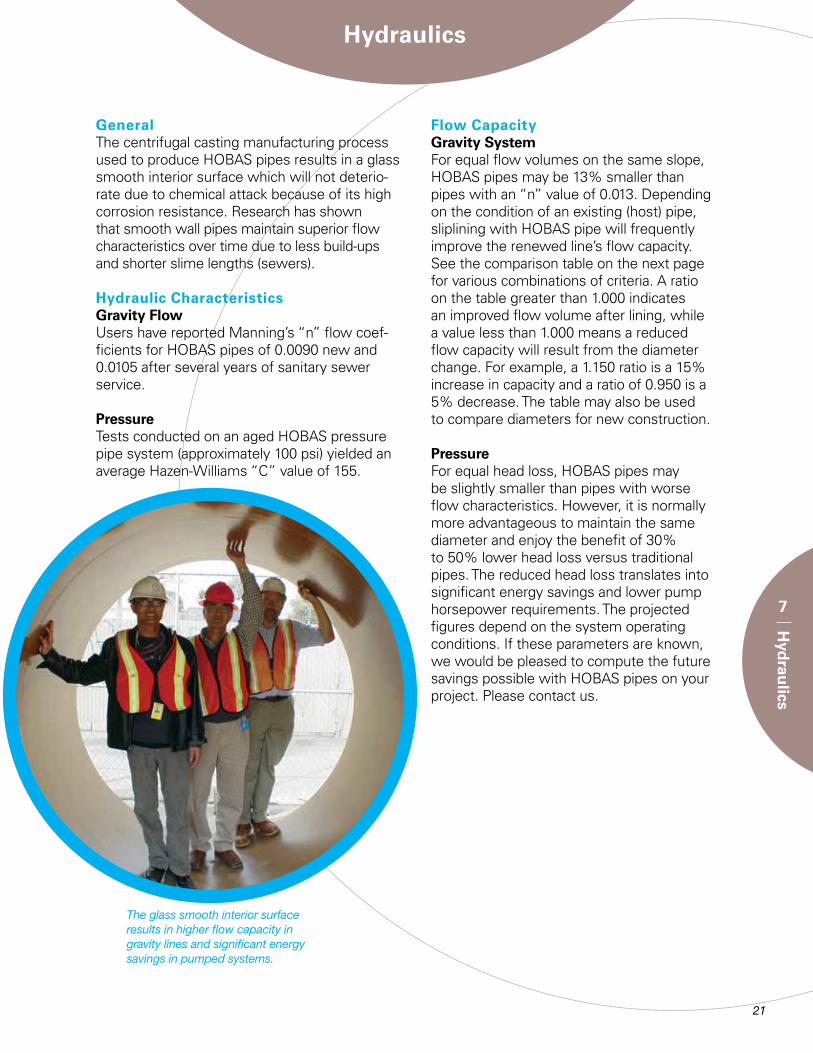
Flow CapacityGravity SystemFor equal flow volumes on the same slope, HOBAS pipes may be 13% smaller than pipes with an “n” value of 0.013. Depending on the condition of an existing (host) pipe, sliplining with HOBAS pipe will frequently improve the renewed line’s flow capacity. See the comparison table on the next page for various combinations of criteria. A ratio on the table greater than 1.000 indicates an improved flow volume after lining, while a value less than 1.000 means a reduced flow capacity will result from the diameter change. For example, a 1.150 ratio is a 15% increase in capacity and a ratio of 0.950 is a 5% decrease. The table may also be used to compare diameters for new construction.
PressureFor equal head loss, HOBAS pipes may be slightly smaller than pipes with worse flow characteristics. However, it is normally more advantageous to maintain the same diameter and enjoy the benefit of 30% to 50% lower head loss versus traditional pipes. The reduced head loss translates into significant energy savings and lower pump horsepower requirements. The projected figures depend on the system operating conditions. If these parameters are known, we would be pleased to compute the future savings possible with HOBAS pipes on your project. Please contact us.
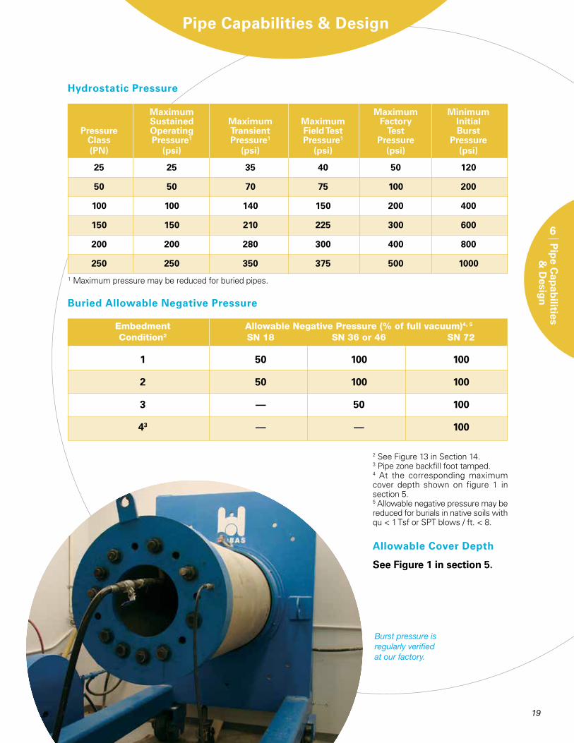
The glass smooth interior surface results in higher flow capacity in gravity lines and significant energy savings in pumped systems.
HO
BA
S R
elin
ing
Pip
e Fl
ow C
oef
fici
ents
, n
Host Pipe Existing Flow Coefficient, n
QHOBAS / QExisting
22 23
7
Hyd
raulics
0.013 0.014 0.015 0.016 0.017 0.018 0.020 0.022 0.024 18 0.009 0.722 0.777 0.833 0.888 0.944 0.999 1.110 1.221 1.332 into 0.010 0.649 0.699 0.749 0.799 0.849 0.899 0.999 1.099 1.199 24 0.011 0.590 0.636 0.681 0.727 0.772 0.817 0.908 0.999 1.090 20 0.009 0.961 1.035 1.109 1.183 1.257 1.331 1.479 1.627 1.774 into 0.010 0.865 0.932 0.998 1.065 1.131 1.198 1.331 1.464 1.597 24 0.011 0.786 0.847 0.907 0.968 1.028 1.089 1.210 1.331 1.452 24 0.009 0.860 0.926 0.992 1.059 1.125 1.191 1.323 1.456 1.588 into 0.010 0.774 0.834 0.893 0.953 1.012 1.072 1.191 1.310 1.429 30 0.011 0.704 0.758 0.812 0.866 0.920 0.974 1.083 1.191 1.299 30 0.009 0.945 1.017 1.090 1.163 1.235 1.308 1.453 1.599 1.744 into 0.010 0.850 0.916 0.981 1.046 1.112 1.177 1.308 1.439 1.570 36 0.011 0.773 0.832 0.892 0.951 1.011 1.070 1.189 1.308 1.427 36 0.009 1.008 1.086 1.163 1.241 1.318 1.396 1.551 1.706 1.861 into 0.010 0.907 0.977 1.047 1.117 1.186 1.256 1.396 1.535 1.675 42 0.011 0.825 0.888 0.952 1.015 1.079 1.142 1.269 1.396 1.523 42 0.009 1.057 1.139 1.220 1.301 1.383 1.464 1.627 1.789 1.952 into 0.010 0.952 1.025 1.098 1.171 1.244 1.318 1.464 1.610 1.757 48 0.011 0.865 0.932 0.998 1.065 1.131 1.198 1.331 1.464 1.597 48 0.009 1.103 1.187 1.272 1.357 1.442 1.527 1.696 1.866 2.036 into 0.010 0.992 1.069 1.145 1.221 1.298 1.374 1.527 1.679 1.832 54 0.011 0.902 0.972 1.041 1.110 1.180 1.249 1.388 1.527 1.666 54 0.009 1.140 1.227 1.315 1.403 1.490 1.578 1.754 1.929 2.104 into 0.010 1.026 1.105 1.184 1.263 1.341 1.420 1.578 1.736 1.894 60 0.011 0.933 1.004 1.076 1.148 1.219 1.291 1.435 1.578 1.722 60 0.009 1.145 1.233 1.322 1.410 1.498 1.586 1.762 1.938 2.114 into 0.010 1.031 1.110 1.189 1.269 1.348 1.427 1.586 1.744 1.903 66 0.011 0.937 1.009 1.081 1.153 1.225 1.298 1.442 1.586 1.730 66 0.009 1.173 1.264 1.354 1.444 1.534 1.625 1.805 1.986 2.166 into 0.010 1.056 1.137 1.218 1.300 1.381 1.462 1.625 1.787 1.949 72 0.011 0.960 1.034 1.108 1.182 1.255 1.329 1.477 1.625 1.772 72 0.009 1.193 1.285 1.376 1.468 1.560 1.652 1.835 2.019 2.202 into 0.010 1.074 1.156 1.239 1.321 1.404 1.487 1.652 1.817 1.982 78 0.011 0.976 1.051 1.126 1.201 1.276 1.351 1.502 1.652 1.802 78 0.009 1.210 1.303 1.396 1.489 1.582 1.675 1.861 2.048 2.234 into 0.010 1.089 1.173 1.256 1.340 1.424 1.508 1.675 1.843 2.010 84 0.011 0.990 1.066 1.142 1.218 1.295 1.371 1.523 1.675 1.828 84 0.009 1.194 1.286 1.378 1.470 1.562 1.653 1.837 2.021 2.204 into 0.010 1.075 1.157 1.240 1.323 1.405 1.488 1.653 1.819 1.984 90 0.011 0.977 1.052 1.127 1.202 1.278 1.353 1.503 1.653 1.804 85 0.009 1.054 1.135 1.216 1.297 1.378 1.459 1.622 1.784 1.946 into 0.010 0.949 1.022 1.095 1.168 1.240 1.313 1.459 1.605 1.751 96 0.011 0.862 0.929 0.995 1.061 1.128 1.194 1.327 1.459 1.592 96 0.009 1.225 1.320 1.414 1.508 1.602 1.697 1.885 2.074 2.262 into 0.010 1.103 1.188 1.273 1.357 1.442 1.527 1.697 1.866 2.036 102 0.011 1.003 1.080 1.157 1.234 1.311 1.388 1.542 1.697 1.851 96 0.009 1.052 1.133 1.214 1.295 1.376 1.457 1.619 1.781 1.942 into 0.010 0.947 1.020 1.093 1.165 1.238 1.311 1.457 1.603 1.748 108 0.011 0.861 0.927 0.993 1.060 1.126 1.192 1.324 1.457 1.589 104 0.009 1.134 1.221 1.308 1.395 1.483 1.570 1.744 1.919 2.093 into 0.010 1.020 1.099 1.177 1.256 1.334 1.413 1.570 1.727 1.884 114 0.011 0.928 0.999 1.070 1.142 1.213 1.284 1.427 1.570 1.712 110 0.009 1.143 1.230 1.318 1.406 1.494 1.582 1.758 1.934 2.109 into 0.010 1.028 1.107 1.187 1.266 1.345 1.424 1.582 1.740 1.898 120 0.011 0.935 1.007 1.079 1.151 1.222 1.294 1.438 1.582 1.726 120 0.009 1.152 1.240 1.329 1.417 1.506 1.595 1.772 1.949 1.126 into 0.010 1.036 1.116 1.196 1.276 1.355 1.435 1.596 1.754 1.914 132 0.011 0.942 1.015 1.087 1.160 1.232 1.305 1.450 1.595 1.740 * HOBAS diameters are nominal for 36psi stiffness ** Existing sewer assumed full size. Nominal Diameter = I.D.

23
Joints
8
Join
ts
Joint Designs Several joint designs are available to meet the requirements of many different applications. The FWC coupling is normally utilized for direct bury, aboveground, and some other installations. For sliplining, jacking, and tunnel installations, special joints are available. Closure couplings are available for tie-ins. Joint dimensions are given in Appendix C.
Joint Selection
* May use flush bell-spigot joint in very tight fit situations.** May use FWC coupling in some situations.
Direct Bury FWC Coupling FWC Coupling
Jacking Flush Flush Bell-Spigot FWC Coupling
Low Profile Pressure Bell-Spigot* Relining
Sliplining
Aboveground FWC Coupling FWC Coupling Tunnel Carrier Pipe Flush Pressure Relining Bell-Spigot** Tie-ins Closure Coupling Steel Mechanical Coupling
Service Installation Non-Pressure Pressure
Minimum Radius of Curvature for Various Deflected Joints
Joining Forces for HOBAS Couplings
Approximate average straight alignment (pounds)
Nominal Avg. FWC Flush Pipe Size Joining and LPB (in) Force (lbs.) (lbs.)
18 3150 2150 20 3500 2350 24 4200 2850 27 4725 3200 28 4900 3300 30 5250 3550 33 5775 3900 36 6300 4250 41 7175 4800 42 7350 4950 44 7700 5150 45 7875 5300 48 8400 5650 51 8925 6000 54 9450 6350 57 9975 6700 60 10500 7050 63 11025 7400 66 11550 7750 69 12075 8100 72 12600 8450 78 13650 9150 84 14700 9850 85 14875 9950 90 15750 10550 96 16800 11250 104 18200 12200 110 19250 12850 120 21000 14050 126 22000 14700
Note: Always join pipes in “straight” alignment and then offset to the desired angle afterwards.
Max Max Offset (inches) Min Radius of Deflected Curvature (feet) Angle in Degrees Section Length (feet) Section Length (feet) 5 10 20 5 10 20 3 3 6 12 95 191 382 2 2 4 8 143 286 573 1.75 1.75 3.5 7 164 327 655 1.5 1.5 3 6 191 382 764 1.25 1.25 2.5 5 229 458 917 1 1 2 4 286 573 1146 0.75 0.75 1.5 3 383 764 1528 0.5 0.5 1 2 573 1146 2292* See specific joints for capability

FWC Coupling
Description & CapabilityThe FWC coupling is a structural filament wound sleeve overwrapped and mechanically locked to an internal full-face elastomeric membrane. The sealing design includes both lip and compression elements so the joint is suitable for both non-pressure and for pressure service up to 250 psi. The coupling is factory assembled to one end of each pipe for ease of use in the field.
Per the performance requirements of ASTM D4161, the FWC joint will remain leak-free from twice the rated class pressure to a -0.8 atmosphere vacuum under pres-sure even when angularly turned and vertically deflected. HOBAS pipes, because of their constant OD and their centrifugally cast mold smooth exterior surface, may be joined with the FWC coupling at any place along their entire length with no preparation or machining other than chamfering of the pipe ends.
FWC Joint Gap & Angular Deflection
*This is just a summary table. Contact HOBAS for specific diameter capability.
FWC coupling.
HOBAS FWC coupling.
Pushing home HOBAS FWC coupling with a backhoe bucket makes assembly fast & easy.
HOBAS FWC couplings are tested internally and externally (shown) to prove leak-free capability.
24 25
8
Join
ts
Diameter Coupling Joint Gap Max Deflection (inches) Width (inches)* (inches) Angle, (degrees) 18-20 8 1 3 24-33 10 1 2 36-42 10 1 1.5 44-54 10 1 1 57-60 11.5 1 1 63-78 11.5 1 0.75 84-110 11.5 1 0.5 120-126 13.75 1 0.5
25
8
Join
tsRubber-ring-sealed low profile bell-spigot joints provide a positive seal.
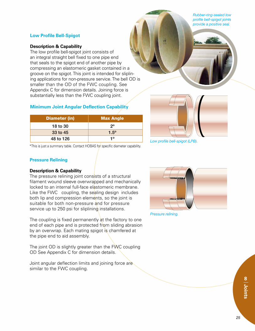
Low Profile Bell-Spigot
Description & CapabilityThe low profile bell-spigot joint consists of an integral straight bell fixed to one pipe end that seals to the spigot end of another pipe by compressing an elastomeric gasket contained in a groove on the spigot. This joint is intended for sliplin-ing applications for non-pressure service. The bell OD is smaller than the OD of the FWC coupling. See Appendix C for dimension details. Joining force is substantially less than the FWC coupling joint.
Low profile bell-spigot (LPB).
Diameter (in) Max Angle
18 to 30 2º 33 to 45 1.5º 48 to 126 1º
Minimum Joint Angular Deflection Capability
Pressure Relining
Description & CapabilityThe pressure relining joint consists of a structural filament wound sleeve overwrapped and mechanically locked to an internal full-face elastomeric membrane. Like the FWC coupling, the sealing design includes both lip and compression elements, so the joint is suitable for both non-pressure and for pressure service up to 250 psi for sliplining installations.
The coupling is fixed permanently at the factory to one end of each pipe and is protected from sliding abrasion by an overwrap. Each mating spigot is chamfered at the pipe end to aid assembly.
The joint OD is slightly greater than the FWC coupling OD See Appendix C for dimension details.
Joint angular deflection limits and joining force are similar to the FWC coupling.
Pressure relining.
*This is just a summary table. Contact HOBAS for specific diameter capability.

26 27
8
Join
ts
Flush Bell-Spigot
Description & CapabilityThe flush bell-spigot joint consists of an integral straight bell fixed to one pipe end that seals to the spigot end of another pipe by compressing an elastomeric gasket contained in a groove on the spigot. The joint has approxi-mately the same OD as the pipe, so when assembled, the joint is essentially flush with the pipe outside surface. It is designed for nonpressure service in jacking and tunnel carrier installations, although it may be used in nonpres-sure relining applications. Typical allowable joint angular deflection is between 1 and 2 degrees depending on the spacer thickness and joint configuration. Joining force is substantially less than the FWC coupling joint.
* The corresponding angle for each allowable joint gap may be calculated by using the formula: deflection angle in degrees = arctan (gap in inches/O.D.in inches).* This joint gap is provided for sealing purposes only and does not address installation loads. See Section 14 for installation specific information.*This is just a summary table. Contact HOBAS for specific diameter capability.
Flush bell-spigot.
Flush Joint Gap*
Nominal Diameter (in) Gap (in)
18 to 28 0.60 30 to 44 0.70 45 to 63 1.36 66 to 126 2.00
Jacking pipes have rubber-ring-sealed flush bell-spigot joints for quick assembly.
26 27
8
Join
ts
Closure Couplings
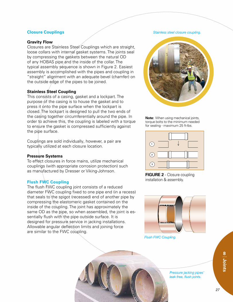
Gravity FlowClosures are Stainless Steel Couplings which are straight, loose collars with internal gasket systems. The joints seal by compressing the gaskets between the natural OD of any HOBAS pipe and the inside of the collar. The typical assembly sequence is shown in Figure 2. Easiest assembly is accomplished with the pipes and coupling in “straight” alignment with an adequate bevel (chamfer) on the outside edge of the pipes to be joined.
Stainless Steel CouplingThis consists of a casing, gasket and a lockpart. The purpose of the casing is to house the gasket and to press it onto the pipe surface when the lockpart is closed. The lockpart is designed to pull the two ends of the casing together circumferentially around the pipe. In order to achieve this, the coupling is labeled with a torque to ensure the gasket is compressed sufficiently against the pipe surface.
Couplings are sold individually, however, a pair are typically utilized at each closure location.
Pressure SystemsTo effect closures in force mains, utilize mechanical couplings (with appropriate corrosion protection) such as manufactured by Dresser or Viking-Johnson.
Flush FWC CouplingThe flush FWC coupling joint consists of a reduced diameter FWC coupling fixed to one pipe end (in a recess) that seals to the spigot (recessed) end of another pipe by compressing the elastomeric gasket contained on the inside of the coupling. The joint has approximately the same OD as the pipe, so when assembled, the joint is es-sentially flush with the pipe outside surface. It is designed for pressure service in jacking installations. Allowable angular deflection limits and joining force are similar to the FWC coupling.
Flush FWC Coupling.
Pressure jacking pipes’ leak-free, flush joints.
Stainless steel closure coupling.
FIGURE 2 - Closure coupling installation & assembly.
Note: When using mechanical joints, torque bolts to the minimum needed for sealing - maximum 25 ft-lbs.

28 29
8
Join
ts
Connections to Other Pipe Material SystemsConnections to other pipe material systems may be accomplished by several methods. Because of compatible OD’s, HOBAS pipes, 18” to 48”, may be joined directly with ductile iron pipes using either our couplings or ductile iron gasketed joints. In some diameters and applications, Fernco couplings may be suitable. Additionally, HOBAS Pipe USA can frequently custom fabricate the mating bell or spigot for other gasket-sealed systems when the proper dimensions are known. Further, custom fabricated mechanical couplings capable of connecting pipes of different OD’s maybe utilized. Although typically the most expensive method, flanges built to ANSI or other drilling specs may also be used. Contact us regarding suitability of or experience with other procedures.
Note: When using mechanical joints, torque bolts to the minimum needed for sealing - maximum 25 ft.-lbs.
HOBAS pipes’ OD is compatible with DI joints from 18” to 48”.
Fiberglass bell fabricated to mate to RCP spigot.
Special spigot end to join with RCP bell.
Joining HOBAS pipes (left) to ductile iron with a HOBAS FWC coupling.

29
9
Fitting
sFittings
GeneralFigure 3 shows the general configuration of standard HOBAS Pipe USA fittings, although almost any mitered fitting can be constructed. These fittings are available for all non-pressure and for many pressure applications. All branch fittings (tees, wyes) must be prevented from deforming. Typically this is accomplished by concrete encasement. Pressure applications will require thrust restraints and may require full encasement in reinforced concrete to resist deformation due to internal pressure. Contact HOBAS Pipe USA for assistance to determine details and requirements for your specific situation. Dimensions for standard fittings are given in Appendix E. Details for diameter combinations and angles not shown or for other fitting configurations are available upon request.
FIGURE 3 - Fittings
Almost any fitting configuration and angle can be constructed with HOBAS fiberglass reinforced polymer mortar pipe.
30 31
9
Fitting
s
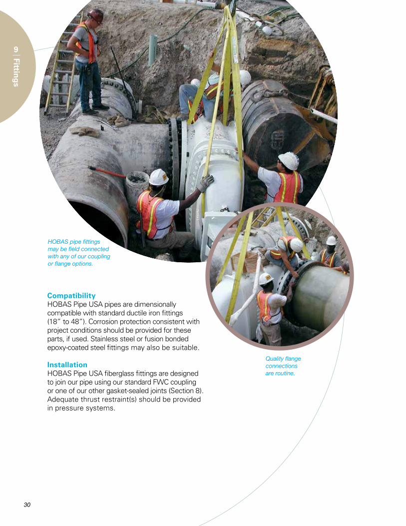
CompatibilityHOBAS Pipe USA pipes are dimensionally compatible with standard ductile iron fittings (18” to 48”). Corrosion protection consistent with project conditions should be provided for these parts, if used. Stainless steel or fusion bonded epoxy-coated steel fittings may also be suitable.
InstallationHOBAS Pipe USA fiberglass fittings are designed to join our pipe using our standard FWC coupling or one of our other gasket-sealed joints (Section 8). Adequate thrust restraint(s) should be provided in pressure systems.
HOBAS pipe fittings may be field connected with any of our coupling or flange options.
Quality flange connections are routine.

31
10
Man
ho
les
HOBAS pipes can be used with a wide variety of commercially available manholes including:
• HOBAS tee base system• Precast concrete• Cast-in-place concrete
Others may be adaptable. Please consult us for assistance.
HOBAS Tee Base System
Description & VersatilityThe HOBAS tee base manhole system consists of a HOBAS tee base and a one-piece fiberglass riser (two options available - Figures 4 & 5). As shown, the manhole in Figure 5 is not suitable for traffic loading, although options for that condition are available. Consult manufacturer for limitations on riser loading and flat top weight. The tee base is available with mitered angles for alignment changes. The HOBAS tee base may also be used with RCP riser sections.
Assembly & InstallationThe tee base is assembled to both the mainline sewer pipe and the fiberglass riser section with HOBAS push-on, gasket-sealed FWC couplings (see Section 8). Fully concrete encase the tee base so only the indicated length of the riser neck remains exposed. In most cases, the concrete encasement must be designed to support all riser loads and extend past the nearest couplings. More detailed instructions are available. Place the riser sections after the concrete cures.
HOBAS tee base manholes are available in any size and angle.
FIGURE 4 – HOBAS Tee Base Manhole System with Riser & Cone
Item Description
A HOBAS Line Pipe
B HOBAS Tee Base
C HOBAS FWC Coupling
D Fiberglass Riser with Cone
E Concrete Encasement
F HOBAS FWC Coupling and Riser Invert
H Riser Height (2 to 40 )
ID Riser ID (48”, 60”, 72”)
FIGURE 5 – HOBAS Tee Base Manhole System with Riser & Flat Top
Item Description
A HOBAS Line Pipe
B HOBAS Tee Base
C HOBAS FWC Coupling
D HOBAS Riser Pipe
E Concrete Encasement
F Concrete Flat Top
H Riser Height (2 to 20 )
ID Riser ID (Equal to neck Dia.≤ line Dia.)
Manholes

32
10
Man
ho
les
Pre-Cast or Cast-in-place ManholesHOBAS pipes can be easily connected by traditional methods to many pre-cast or
cast-in-place concrete manholes as shown in Figures 6, 7, 8 and 9. Other methods may be suitable. Contact us for assistance.
* Such as A-Lok or Press-Seal Econoseal
** Such as Kor-N-Seal or Press-Seal PSX
*** In large diameters it may be best to utilize a rigid encasement adjacent to the structure.
FIGURE 6 – Cast-In Gasket Connection
FIGURE 8 - HOBAS FWC Wall Fitting Connection
FIGURE 7 – Expandable Boot Seal Connection
FIGURE 9 – Grout with Water-Stop Connection

32 33
Pipe ManufacturingProcess
11
Pip
e Man
ufactu
ring
Pro
cess
Centrifugal Casting ProcessHOBAS fiberglass reinforced polymer mortar pipes are produced by a unique centrifugal casting process. The sophisticated pipe wall structure is built up from the outside surface to the interior surface within an external rotating mold. While the mold is revolving at a relatively slow speed, the pipe raw materials of thermoset-ting resin, reinforcing glass fibers and aggregates are precisely distributed in specific layers at computer controlled rates. The resin is specially formulated to not polymerize during the filling process. When all the material has been positioned, the mold rotational speed is increased to produce centrifugal forces of up to 75g while the polymerization of the resin begins. These forces compress the composition against the mold causing total deaeration and full compac-tion. In a short time thereafter, the completed, cured pipe is removed from the mold.
The centrifugal casting process produces a superior, high density fiberglass reinforced polymer mortar pipe product. Because the process is fully computer controlled, all pipes of each size, stiffness and pressure class have very consistent, high quality. All pipes also have a mold smooth exterior surface and an equally smooth, centrifugally cast interior surface.
Because the pipe materials are placed in many layers, the wall structure can be varied to produce the desired and most economical characteristics for most applications, pressure
or non-pressure. Typically, the reinforcing glass-fiber layers are predominantly positioned near the two pipe surfaces, on both sides of the bending neutral axis. The intermediate space is comprised primarily of a glass-fiber fortified aggregate and resin mixture. By virtue of this “sandwich” construction, the pipe wall reacts to bending like an l-beam (Figure 10).
The centrifugal casting process and sophis-ticated pipe wall structure combine to make HOBAS pipes the most technically advanced fiberglass pipes available today.
FIGURE 10 - I-Beam Effect In Pipe Wall Bending
Sophisticated materials feeding process for HOBAS centrifugally cast pipe production.

34
Pip
e M
anu
facturin
g P
rocess
11
Pipe materials feeders are computer controlled. This helps assure consistent high quality. Multiple facilities around the world manufacture CCFRPM pipe using HOBAS technology.
Fabrication of HOBAS FWChigh strength coupling.
Reinforcing fibers are distributed in specific layers at computer controlled rates that are monitored continuously.

34 35
12
Qu
ality Co
ntro
lQuality Control
The constituent raw materials and the pipe production are routinely sampled and tested according to ASTM and AWWA standards to confirm that the desired characteristics and design performance are consistently maintained.
Raw Materials
ResinAll resin shipments have certified test results from the manufacturer for over 10 critical characteristics. Our laboratory randomly verifies these parameters.
Glass FibersThe lots are checked for moisture, yield and sizing/binder content.
AggregateShipments are monitored for gradation, moisture content and impurities.
The quality of each of the raw materials components is routinely verified.
Raw material properties are checked to ensure suitability.
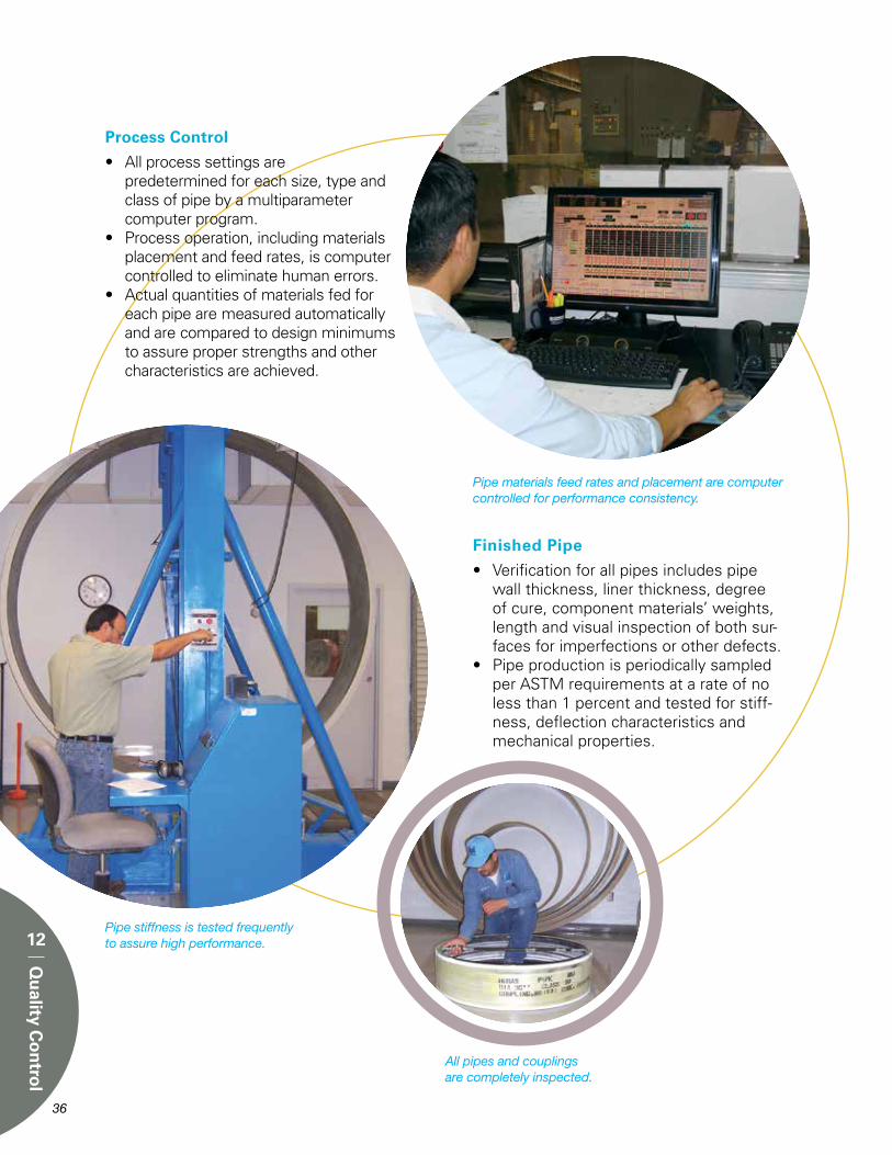
Process Control
• All process settings are predetermined for each size, type and
class of pipe by a multiparameter computer program.
• Process operation, including materials placement and feed rates, is computer controlled to eliminate human errors.
• Actual quantities of materials fed for each pipe are measured automatically and are compared to design minimums to assure proper strengths and other characteristics are achieved.
Finished Pipe
• Verification for all pipes includes pipe wall thickness, liner thickness, degree of cure, component materials’ weights, length and visual inspection of both sur-faces for imperfections or other defects.
• Pipe production is periodically sampled per ASTM requirements at a rate of no less than 1 percent and tested for stiff-ness, deflection characteristics and mechanical properties.
Pipe materials feed rates and placement are computer controlled for performance consistency.
Pipe stiffness is tested frequently to assure high performance.
All pipes and couplings are completely inspected.
36 37
12
Qu
ality Co
ntro
l

37
13
Stan
dard
sStandards
ASTM and AWWA standards define requirements for HOBAS pipes for most applications.
Product StandardsHOBAS Pipe USA manufactures pipes according to the applicable U.S. product standards as follows:
Application Standard
Non-pressure Sanitary ASTM D3262 Sewers
Sewer Force Mains ASTM D3754 Industrial Effluents (Pressure)
Pressure Water AWWA C950 Systems
Fiberglass Pipe AWWA M45 Design
All of these standards include quality control requirements for:
• Workmanship• Dimensions• Pipe Stiffness• Ring Deflection without Cracking• Ring Deflection without Failure• Hoop Tensile Strength• Axial Tensile Strength
Routine TestingRoutine testing on HOBAS Pipe USA production is conducted to assure full compliance is maintained.
Long-Term Performance & DurabilityLong-term performance and durability is measured by extended pressure and ring bending tests that continue for a minimum of 10,000 hours. Test results are extrapolated by regression analysis per ASTM standards to determine the 50 year performance value. Safe operating limits are established by applying design factors as given in the AWWA Fiberglass Pipe Design Manual, M45.

38 39
ASTM D638 Tensile Properties by Coupon
ASTM D3567 Dimensions
ASTM D2992 HDB Procedure
ASTM D2584 Composition by Loss on Ignition
ASTM D2583 Barcol Hardness (cure)
ASTM D2412 Pipe Stiffness
ASTM D2290 Tensile Strength by Split Disk
ASTM D1599 Quick Burst
ASTM D695 Compression by Coupon
ASTM D3681 Chemical Resistance - Deflected
Test
Designation Purpose
HOBAS Pipe USA pipes are acid tested per ASTM requirements for sanitary sewers.
Test MethodsThe listed test methods are used to measure the pipe performance and characteristics:
13
Stan
dard
s

39
14
Installatio
nInstallation
A Direct BuryA1 Trench Construction
A1.1 Trench width The minimum trench width shall provide sufficient working room at the sides of the pipe to permit accurate placement and adequate compaction of the pipe zone backfill material. Suggested minimum trench dimensions are given in Figure 11.
A1.1.1 Wide trenchesThere is no maximum limit on trench width, however, it is required that the pipe zone backfill material be placed and compacted as specified for the full width of the trench or a distance of two diameters on each side of the pipe, whichever is less.
A1.2 Supported trenchWhen a permanent or temporary trench shoring is used, minimum trench width shall be as per paragraph A1.1 and Figure 11. When using movable trench supports, care should be exercised not to disturb the pipe location, jointing or its embedment. Removal of any
trench protection below the top of the pipe and within two pipe diameters is not recom-mended after the pipe embedment has been compacted unless all voids created by sheet-ing removal are filled with properly densified embedment material and any loose soils at pipe zone elevation are properly compacted prior to loading the pipe with overburden. When possible, use movable trench supports on a shelf above the pipe with the pipe installed in a narrow, vertical wall subditch.
A1.3 Dewatering Where conditions are such that running or standing water occurs in the trench bottom or the soil in the trench bottom displays a “quick” tendency, the water should be removed by pumps and suitable means such as well points or underdrain bedding. This system should be maintained in operation until the backfill has been placed to a sufficient height to prevent pipe flotation. Care should be taken that any underdrain is of proper gradation and thickness to prevent migration of material between the underdrain, pipe embedment and native soils in the trench, below and at the sides of the pipe.
FIGURE 11 - Standard Trench Dimensions
Typical Min. a (in.)
DN (in.) SPT2 ≤ 8 SPT2 > 8
18 to 20 6 4
24 to 33 9 6
36 to 48 12 8
51 to 72 18 12
78 to 126 24 16
Typical 6”

40 41
A1.4 Preparation of Trench BottomThe trench bottom should be con-structed to provide a firm, stable and uniform support for the full length of the pipe. Bell holes (Figure 12) should be provided at each joint to permit proper joint assembly and alignment. Any part of the trench bottom excavated below grade should be backfilled to grade and should be compacted as required to provide firm pipe support. When an unstable subgrade condition is encountered which will provide inadequate pipe support, additional trench depth should be excavated and refilled with suitable foundation material. In severe conditions special foundations may be required such as wood pile or sheeting capped by a concrete mat, wood sheeting with keyed-in plank foundation, or foundation material processed with cement or chemical stabilizers. A cushion of acceptable bedding material should always be provided between any special foundation and the pipe. Large rocks and debris should be removed to provide four inches of soil cushion below the pipe and accessories.
A2 Standard Embedment ConditionsFour standard embedment conditions are given in Figure 13. Others may be acceptable. Please consult us for advice on options.
A3 Pipe Zone (Embedment) Backfill MaterialsMost coarse grained soils as classified by ASTM D2487, Classification of Soils for Engineering Purposes, are acceptable bedding and pipe zone (embedment) backfill materials as given in the adjacent table.
FIGURE 12 - Bell Holes
Note: After joint assembly, fill the bell holes with bedding material and compact as required.
FIGURE 13 - Standard Embedment Conditions
2 Gravel is defined in section 14, paragraph A33 Sand is defined in section 14, paragraph A34 RD is relative density per ASTM D4253.5 SPD is standard proctor density per ASTM D698.
Specification Definition
Gravel or GW, GP Gravel crushed rock GW-GC, GW-GM GP-GC, GP-GM
Sand or SW, SP Sand sand-gravel SW-SC, SW-SM mixtures SP-SC, SP-SM
Symbols
14
Installatio
n

41
Maximum grain size should typically not exceed 1 to 11/2 times the pipe wall thick-ness or 11/2 inches whichever is smaller.
Well graded materials that will minimize voids in the embedment materials should be used in cases where migration of fines in the trench wall material into the embed-ment can be anticipated. Alternatively, separate the open graded material from the non-cohesive soil with a filter fabric to prevent migration of the smaller grained soil into the open graded material. Such migration is undesirable since it would reduce the soil density near the pipe zone and thereby lessen the pipe support.
Embedment materials should contain no debris, foreign or frozen materials.
A4 BeddingA firm, uniform bed should be prepared to fully support the pipe along its entire length (Figure 14). Bedding material should be as specified on Figure 13 and in paragraph A3. Bedding minimum depth should be equal to 25% of the nominal diameter or six inches, whichever is less (Figure 11).
FIGURE 14 - Bedding
FIGURE 15 - Haunching
14
Installatio
n
A firm trench bottom must be provided (see paragraphs A1.3 and A1.4). Initially place and compact bedding to achieve 2/3 of the total bed thickness (normally four inches). Loosely place the remaining bedding material to achieve a uniform soft cushion in which to seat the pipe invert (bottom).
After joining pipes, assure that all bell holes are filled with the appropriate embedment materials and compacted as specified.
Note: Do not use blocking to adjust pipe grade.
A5 HaunchingA very important factor affecting pipe performance and deflection is the haunch-ing material and its density. Material should be placed and consolidated under the pipe (Figure 15) while avoiding both vertical and lateral displacement of the pipe from proper grade and alignment.
A6 BackfillingPipe zone (embedment) material shall be as specified on Figure 13 and in paragraph A3. (It must be the same as the bedding mate-rial to prevent potential migration.)
Place and compact the embedment material in lifts to achieve the depths and densities specified on Figure 13. Little or no tamping of the initial backfill directly over the top of the pipe should be done to avoid disturbing the embed-ded pipe.
Remaining backfill may be the native trench material provided clumps and boulders larger than three to four inches in size are not used until 12 inches of pipe cover has been achieved.

42
14
Installatio
n
A6.1 Maximum Cover Depth Maximum recommended cover depth is given in Figure 16.
A6.2 Minimum Cover for Traffic Load Application Minimum recommended cover depth of compacted fill above the pipe crown prior to application of vehicle loads is given in the above chart. Installation in poor soils or at shallower cover depths is possible by using a surface bridging slab or pipe encasement in concrete or similar.
A7 Pipe DeflectionPipe initial vertical cross-section deflection measured within the first 24 hours after completion
of all backfilling and removal of dewatering systems, if used, shall not exceed 3% of the original pipe diameter. (See Appendix G for minimum inside diameters.)
Pipe deflection after 30 days should typically not exceed 4% of the original pipe diameter. Maximum long-term pipe deflection is 5% of the original pipe diameter. (See Appendix G for minimum inside diameters.) Maximum long-term deflection for pipes with vinyl ester resin liner is 4%.
For very high stiffness pipes (approx. SN 120 and above), the maximum long-term deflection may be reduced and the 24 hour and 30 day deflection limits also decreased proportionally.
A8 Alternate InstallationsAlternate installations, as indicated on Figure 16, include cement stabilized embedment, wide trenching, permanent sheeting, geo-fabrics or combinations of these systems. Installation design for these situations should be engineered to satisfy the specific conditions and circumstances that are present.
FIGURE 16 - Maximum Cover Depth1
1 See Figure 13. 2 Installation in poor soils or at shallower cover depths is possible with improved pipe support such as cement stabilized sand or concrete encasement.
Embedment Minimum Cover (ft) for HS20 Load2
Condition1 SN 18 SN 36 or 46 SN 72
1 4 3 2
2 5 4 3
3 – 5 4
4 – – 5
NATIVE SOIL 2, 5 COVER EMBEDMENT CONDITION3
DEPTH1
(ft.) 1 2 3 4
1 Assuming typ. 1.5 x OD Trench Width (or as in Figure 11) 2 Soils adjacent to pipe (pipe zone elevation)3 Defined in Figure 13 4 For zero blow (weight of hammer) soils, use Alternate Installation & SN 725 SN is nominal stiffness in PSI6 Alternate Installation per section 14, A8-Typ. SN 72 min.
10 & <
>10 to 20
>20 to 30
>30 to 40
>40 to 50
>50 to 60
>60 to 70
10 & <
>10 to 20
>20 to 30
>30 to 40
10 & <
>10 to 20
>20 to 30
10 & <
>10 to 20
ROCK
Stiff to V. Hard Cohesive (Qu ≥ 1 Tsf)
Compact to V. Dense Granular (SPT N ≥ 8 bpf)
Medium Cohesive (Qu ≥ 0.5 Tsf)
Loose Granular (SPT N = 4 to 7 bpf)
Soft Cohesive (Qu ≥ 0.25 Tsf)
V. Loose Granular (SPT N = 2 to 3 bpf)
V. Soft Cohesive (Qu ≥ 0.125 Tsf)
V. V. Loose Granular (SPT N ~ 1 bpf)
SN 46
SN 72
SN 36
SN 72
SN 72
SN 46
SN 36
SN 72
SN 72
SN 46SN 72
SN 90
SN 72
SN 120
SN 46
SN5 36SN5 72
SN 72
SN 46
SN 36SN 46SN 72
SN 90SN 120Alternate Installation
STIFFNESS CLASS KEY
ALTERNATE INSTALLATION6
ALTERNATE INSTALLATION6
ALTERNATE INSTALLATION6
ALTERNATE INSTALLATION6

42 43
14
Installatio
n
B SlipliningB1 Existing Pipe PreparationThe existing sewer may be maintained in operation during the relining process. Obstructions such as roots, large joint off-sets, rocks or other debris, etc. that would prevent passage or damage the liner pipe sections must be removed or repaired prior to installing the new pipe. Prior to starting the liner insertion, verify the existing pipe diameter is sufficient by pulling a mandrel through the line.
It must be determined that the rehabili-tated pipeline will be sufficient structur-ally to carry the overburden loads for the intended design life.
B2 Liner Pipe InsertionLiner pipes may be pushed or pulled into the existing pipe. The pipes must be inserted spigot end first with the bell end trailing. Sometimes the leading pipe spigot end is protected by a nose piece designed to ride-up and over off-set joints and other minor inconsistencies or debris in the invert. The pushing force must be applied to the pipe wall end inside of the bell as shown in Figure 17. DO NOT apply the pushing load to the end of the bell. Assure that the safe (F of S ≈ 3) jacking loads given in the above table are not exceeded. For pipes with flush bell-spigot joints, see the table on page 48 for typical allowable push loads. Allowable safe jacking loads may be reduced by point loading (i.e. pushing through curves). Maximum allowable joint angular deflection is given on p. 25.
FIGURE 17 - Pipe Insertion
Low-Profile Bell-Spigot Joint Allowable Compressive Load
Small access pits needed for sliplining with HOBAS pipes save time, money and surface disruption.
Nom. Dia. (in.)
O.D. (in.)
PipeWall Bell
Safe Compressive LoadPushing “Straight” (U.S. Tons)SN 36 SN 46 SN72
18 19.5 20.4 – 25 (SN 62) 27 20 21.6 22.5 – 29 36 24 25.8 26.8 39 44 54 27 28.0 29.0 48 54 66 28 30.0 31.0 56 63 77 30 32.0 33.0 51 58 74 33 34.0 35.0 60 67 85 36 38.3 39.3 82 92 115 41 42.9 44.0 108 122 149 42 44.5 45.6 119 134 162 44 45.9 47.0 128 143 175 45 47.7 48.8 141 159 192 48 50.8 51.9 164 183 220 51 53.9 55.0 188 211 254 54 57.1 58.2 215 239 288 57 60.0 61.2 242 268 322 60 62.9 64.1 271 297 358 63 66.0 67.2 302 333 396 66 69.2 70.4 305 342 412 69 72.5 73.8 339 378 458 72 75.4 76.7 373 417 501 78 81.6 82.9 448 496 595 84 87.0 88.4 520 575 686 85 88.6 90.0 544 601 717 90 94.3 95.7 625 690 820 96 99.5 101.0 702 776 924 104 108.0 109.5 844 930 1101 110 114.0 115.5 950 1050 1240 120 126.0 127.5 1190 1300 1535 126 132.5 134.3 1300 1420 1705

44 45
14
Installatio
n
B3 LateralsLaterals may be typically reconnected to the new liner pipe using “Inserta Tees” or similar accessories. B4 GroutingGrout the annular space between the OD of the installed liner pipe and the ID of the existing pipe with a cement or chemical based grout. Minimum com-pressive strength of the grout shall be as required to assure the structural ad-equacy of the rehabilitated pipe. During grout placement, assure that the safe (F of S ≈ 2) grouting pressure given in the table below is not exceeded and that the grout density, lift heights and sewage flow depth are coordinated to control the liner pipe flotation and deformation to within allowable limits.
Notes:Diameter Difference =
(ID Host Pipe - OD Liner Pipe) X 100 OD Liner Pipe
SN is nominal pipe stiffness in psi
DiameterDifference
Fluid Flow Level
Max. Safe Grouting Pressure (psi)
None Over 1/2
or low to full
≤ 5% SN÷4 SN÷3
≤ 10% SN÷5 SN÷4
≤ 20% SN÷6 SN÷5
> 20% SN÷7 SN÷6
Lateral Service reconnection using an “Inserta Tee”.
Underside (inside) of “Inserta Tee” installation.
“Inserta Tee” installed in HOBAS Pipe.

45
C JackingC1 GeneralA boring head begins the tunnel excavation from an access shaft and is pushed along by a hydraulic jacking unit that remains in the pit. The link to the boring head is maintained by adding jacking pipe between the pushing unit and the head. By this procedure, the pipe is installed as the tunnel is bored.
C2 Maximum Allowable Safe Jacking LoadThe jacking contractor must control the jacking loads within the safe limits for the pipe. The adjacent table shows allowable safe jacking loads (pushing “straight”) for the typical design. However, the ultimate pipe load capacity is the choice and responsibility of the purchaser and can be affected by a number of factors including the anticipated loads, the amount of steering, the amount of over-cut, the amount of lubrication, the pipe section length, the distance of the jacking operation and any point loading. Pipes should be jacked bell-trailing.
C3 Tunnel DiameterOvercut the tunnel diameter and lubricate the annular space to minimize jacking loads. Take care to control the external pressure to within the safe buckling capacity of the pipe.
C4 Joint & Pipe DeflectionThe typical allowable joint angular deflection is between one and two degrees depending on the spacer thick-ness and joint configuration. Maximum long-term pipe deflection is typically 3% of the original pipe diameter. For pipes with stiffness exceeding 400 psi, a lower deflection limit normally applies.
FIGURE 18 - Jacking Pipe Spigot End
HOBAS pipes are the only inherently corrosion resistant, resilient product strong enough to safely withstand the high pushing loads for direct jacking.
14
Installatio
n
* Lead times may be lengthy, please inquire.Note: Alternate pipe designs are available upon request.
Allowable Safe Jacking Load Pushing “Straight”
(U.S. Tons)F of S = 3.0
Min. Pipe Wall Thickness @ Gasket
Groove (in.)
Nom. Dia.(in.)
O.D.(in.)
Nom. InsideDia.(in.)
Min. Pipe Wall
Thickness (in.)
Weight (lb/ft)
******
F of S = 2.5
Jacking Bell-Spigot Joint Allowable Compressive Load
24 25.8 22.7 1.40 0.99 125 150 107 27 28.0 24.8 1.47 1.06 145 175 120 28 30.0 26.6 1.53 1.12 166 200 137 30 32.0 28.3 1.71 1.21 191 230 159 33 34.0 30.1 1.80 1.29 216 260 179 36 38.3 34.3 1.85 1.31 250 300 208 41 42.9 38.7 1.91 1.32 283 340 245 42 44.5 40.3 1.93 1.33 295 355 255 44 45.9 41.7 1.95 1.34 308 370 263 45 47.7 43.4 1.98 1.35 325 390 280 48 50.8 46.4 2.03 1.37 350 420 306 51 53.9 49.4 2.07 1.38 375 450 333 54 57.1 52.5 2.10 1.39 400 480 361 57 60.0 55.4 2.13 1.40 425 510 380 60 62.9 58.2 2.16 1.41 450 540 408 63 66.0 61.2 2.20 1.42 475 570 438 66 69.2 64.2 2.31 1.43 500 600 478 69 72.5 67.4 2.38 1.47 541 650 512 72 75.4 70.1 2.46 1.52 583 700 553 78 81.6 76.0 2.58 1.60 667 800 634 84 87.0 81.2 2.70 1.68 750 900 701 85 88.6 82.8 2.73 1.69 770 925 727 90 94.3 88.2 2.85 1.76 854 1025 800 96 99.5 93.1 3.00 1.87 958 1150 886 104 108.0 101.3 3.13 1.94 1083 1300 1009 110 114.0 106.9 3.29 2.05 1208 1450 1129 120 126.0 118.4 3.58 2.25 1470 1765 1350 126 132.5 124.5 3.76 2.37 1600 1920 1500

46
14
Installatio
n
D AbovegroundD1 Support ConfigurationRecommended pipe support configuration for ambient temperatures is shown on Figures 19 & 20. Pipe diameters and classes shown acceptable (Figure 19) for support scheme A (Figure 20) require only one support location per 20 ft. section. This is best accomplished by a single cradle support on each FWC coupling. These pipes may also be supported as shown in scheme B (Figure 20) with cradles on the pipe wall immediately adjacent to both sides of each coupling, however the mid-point support is not required.
Pipe diameters and classes shown acceptable (Figure 19) for support scheme B (Figure 20) require supports on 10 ft. centers. This must include a double pipe wall cradle bridging each FWC coupling and a mid-span pipe wall cradle support.
Special pipe designs are available for elevated temperature applications or longer support spans.
FIGURE 20 - Pipe Support Spacing and Scheme
* At ambient temperature**PN is pipe pressure class in psi+ SN is pipe stiffness class in psi
FIGURE 19 - Pipe Support Configurations
NON-STANDARD
SCHEME AFIGURE 20
PN** 25 & 50 100 150 200 250
DIA. SN+ (In.) 18 36/46 ≥72 ≥18 ≥36 ≥36 ≥72 18 & 20 24 to 28 30 to 36 41 to 45 48 & 51 54 & 57 60 & 63 66 to 72 78 to 126
Pipe Support Configurations*
SCHEME A FIGURE 20 10’ C - CorSCHEME BFIGURE 20
Protection from long-term exposure to ultraviolet rays is typically required to prevent surface degradation to joints and fittings.
Scheme A(Pipe supported and anchored at every coupling)
Scheme B(Pipe supported on pipe wall and anchored once per pipe)
Pipe & Craddle Span Length(Max 20 ft)
DNØ
FWC Coupling(Typ.)
FWC Coupling(Typ.)
Anchor Strap(Typ.)
Anchor Strap(Once per pipe,Typ.)
Pipe Length(Max 20 ft)
Craddle(Typ.)
Craddle(Typ.)
Craddle Span Length(9/16 of Pipe L. Centered on Pipe)
DNØ

46 47
14
Installatio
n
D2 CradlesCradles shall have a minimum 120° support arc and be dimensioned as shown on Figure 21. All cradles shall be faced with a 1/4” thick rubber padding (approx. 50 to 60 durometer).
D3 AnchorsBoth support schemes require one anchored cradle (Figure 21) for each pipe section. The anchor strap over the pipe or coupling shall be padded with rubber to create maximum friction resistance to pipe movement. In support scheme A, all cradle positions (support on FWC coupling) must be anchored. In support scheme B, one pipe wall cradle (near the FWC coupling)
FIGURE 21 - Single Cradle w/Anchor Detail
SUPPORT CRADLE RADIUS TO MIN. CRADLE LOCATION RUBBER FACE WIDTH ON PIPE WALL PIPE O.D.*/2 (SCHEME B)
ON FWC COUPLING WIDTH OF FWC (SCHEME A)
FWC O.D.**/2 COUPLING (8”, 10” or 11 1/2”)
18” to 24” dia. = 3”27” to 44” dia. = 4”45” to 78” dia. = 6”84” to 126” dia. = 8”
per section should be anchored as shown on Figure 20. At the other cradle locations the pipe may be restrained loosely to prevent lateral or vertical movement, but should not be so fixed as to restrict axial sliding.
D4 Pipe RestraintThe pipe support and restraint system must be designed to withstand any unbalanced thrust forces at angularly deflected joints or at fittings that may be developed due to pipe pressurization. Other loads caused by wind, temperature changes, fluid momentum, etc. must also be considered.
Dimensional consistency makes above ground installations with HOBAS pipe easy.

E Tunnel CarrierE1 Carrier Pipe InsertionCarrier pipes may be placed in the tunnel one at a time or may be inserted in a continuous push. If the insertion method involves sliding, the HOBAS carrier pipes must be protected from excessive abrasion. Normally, insert the carrier pipes spigot end first with the pushing force, if used, applied to the pipe wall end inside of the bell as shown in Figure 17 on page 43. DO NOT apply the pushing load to the end of the bell. Assure that the allowable safe (F of S ≈ 3) pushing load given in the adjacent table is not exceeded.
E2 Blocking SchemesThe carrier pipes must be blocked within the tunnel to fix line and grade, and to aid in control of deformation of the carrier pipes during grouting. Two typical blocking schemes are shown in Figures 22 and 23. The actual blocking scheme must be designed so the uplift contact pressure of the blocks on the pipe wall does not exceed allowable limits (maximum contact pressure approxi-mately equal to the pipe stiffness).
48
14
Installatio
n
Flush Relining Bell-Spigot Joint Allowable Compressive Load
20 21.6 0.75 245 0.34 34 48 24 25.8 0.76 160 0.35 42 62 27 28.0 0.76 130 0.35 46 68 28 30.0 0.76 105 0.35 49 73 30 32.0 0.86 130 0.36 54 87 33 34.0 0.87 110 0.37 59 94 36 38.3 0.90 90 0.40 73 110 41 42.9 0.96 83 0.44 91 131 42 44.5 0.99 82 0.46 99 140 44 45.9 1.02 82 0.47 105 148 45 47.7 1.05 80 0.49 114 158 48 50.8 1.09 74 0.51 127 175 51 53.9 1.13 69 0.53 141 192 54 57.1 1.17 65 0.55 155 210 57 60.0 1.21 62 0.58 173 225 60 62.9 1.27 62 0.61 191 251 63 66.0 1.33 62 0.64 211 276 66 69.2 1.45 71 0.66 228 315 69 72.5 1.47 64 0.67 243 335 72 75.4 1.49 59 0.68 257 352 78 81.6 1.53 51 0.71 292 393 84 87.0 1.57 45 0.75 330 430 85 88.6 1.58 43 0.76 342 440 90 94.3 1.66 42 0.82 394 491 96 99.5 1.75 42 0.88 448 547 104 108.0 1.85 39 0.94 521 628 110 114.0 1.94 38 0.99 580 695 120 126.0 2.10 36 1.09 710 829 126 132.5 2.2 36 1.16 780 915
Safe Compressive Load Pushing
“Straight” (U.S. Tons)
Min. Pipe Thickness @ Gasket
Groove(in.)
Min. Pipe Wall
Thickness.(in.)
O.D.(in.)
Nom. Dia.(in.)
Nom.Pipe
Stiffness(psi.)
Wt.lb./ft.
E3 GroutingGrout the annular space between the tunnel I.D. and the carrier pipe O.D. with a cement or chemical based grout. Minimum compressive strength of the grout shall be as required to assure the structural adequacy of the completed installation. During grout placement, assure that both the safe
(F of S ≈ 2) grouting pressure of the carrier pipe (pipe stiffness ÷ 5) is not exceeded and that the grout density, lift heights and blocking scheme are coordinated to control the carrier pipe deformation loads to within allowable limits.
FIGURE 22 - Typical blocking scheme at each flush joint.
FIGURE 23 - Typical blocking scheme at each FWC coupling joint.
HOBAS pipes’ constant OD makes blocking simpler.

A
Ap
pen
dix
48 49
Appendix AGuide Specifications
CCFRPM Pipe for Direct Bury Installation - Gravity ServicePart I General1.01 Section Includes
A. Centrifugally Cast Fiberglass Reinforced Polymer Mortar Pipe. (CCFRPM)
1.02 References A. ASTM D3262 - Standard Specification for “Fiberglass” (Glass-Fiber-Reinforced Thermosetting-Resin) Sewer Pipe. B. ASTM D4161 - Standard Specification for “Fiberglass” (Glass-Fiber-Reinforced Thermosetting-Resin) Pipe Joints Using Flexible Elastomeric Seals. C. ASTM D2412 - Standard Test Method for Determination of External Loading Characteristics of Plastic Pipe by Parallel-Plate Loading.D. ASTM D3681 – Standard Test Method for Chemical Resistance of “Fiber glass” Pipe in a Deflected Condition.E. ASTM D638 – Test Method for Tensile Properties of Plastics.
1.03 Specifications A. The specifications contained herein govern, unless otherwise agreed upon between purchaser and supplier.
Part 2 Products2.01 Materials
A. Resin Systems: The manufacturer shall use only polyester resin systems with a proven history of performance in this particular application. The historical data shall have been acquired from a composite material of similar construction and composition as the proposed product. B. Glass Reinforcements: The reinforcing glass fibers used to manufacture the components shall be of highest quality commercial grade E-glass filaments with binder and sizing compatible with impregnating resins. C. Silica Sand: Sand shall be minimum 98% silica with a maximum moisture content of 0.2%. D. Additives: Resin additives, such as curing agents, pigments, dyes, fillers, thixotropic agents, etc., when used, shall not detrimentally effect the performance of the product. E. Elastomeric Gaskets: Gaskets shall meet ASTM F477 and be supplied by qualified gasket manufacturers and be suitable for the service intended.
2.02 Manufacture and Construction
A. Pipes: Manufacture pipe by the centrifugal casting process to result in a dense, nonporous, corrosion-resistant,
consistent composite structure. The interior surface of the pipes exposed to sewer flow shall provide crack resistance and abrasion resistance. The exterior surface of the pipes shall be comprised of a sand and resin layer which provides UV protection to the exterior. Pipes shall be Type 1, Liner 2, Grade 3 per ASTM D3262.B. Joints: Unless otherwise specified, the pipe shall be field connected with fiberglass sleeve couplings that utilize elastomeric sealing gaskets as the sole means to maintain joint watertightness. The joints must meet the performance requirements of ASTM D4161. Joints at tie-ins, when needed, may utilize gasket-sealed closure couplings. C. Fittings: Flanges, elbows, reducers, tees, wyes, laterals and other fittings shall be capable of withstanding all operating conditions when installed. They may be contact molded or manufactured from mitered sections of pipe joined by glass-fiber-reinforced overlays. Properly protected standard ductile iron, fusion-bonded epoxy- coated steel and stainless steel fittings may also be used. D. Acceptable Manufacturer: HOBAS Pipe USA.
2.03 Dimensions A. Diameters: The actual outside diameter (18” to 48”) of the pipes shall be in accordance with ASTM D3262. For other diameters, OD’s shall be per manufacturer’s literature. B. Lengths: Pipe shall be supplied in nominal lengths of 20 feet. Actual laying length shall be nominal +1, -4 inches. At least 90% of the total footage of each size and class of pipe, excluding special order lengths, shall be furnished in nominal length sections. C. Wall Thickness: The minimum wall thickness shall be the stated design thickness. D. End Squareness: Pipe ends shall be square to the pipe axis with a maximum tolerance of 1/8”.
2.04 Testing A. Pipes: Pipes shall be manufactured and tested in accordance with ASTM D3262. B. Joints: Coupling joints shall meet the requirements of ASTM D4161. C. Stiffness: Minimum pipe stiffness when tested in accordance with ASTM D2412 shall normally be 36 psi.
2.05 Customer InspectionA. The Owner or other designated representative shall be entitled to inspect pipes or witness the pipe manufacturing.
B. Manufacturer’s Notification to Customer: Should the Owner request to see specific pipes during any phase of the manufacturing process, the manufacturer must provide the Owner with adequate advance notice of when and where the production of those pipes will take place.
2.06 Packaging, Handling, ShippingA. Packaging, handling, and shipping shall be done in accordance with the manufacturer’s instructions.
Part 3 Execution3.01 Installation
A. Burial: The bedding and burial of pipe and fittings shall be in accordance with the project plans and specifications and the manufacturer’s requirements (Section 14 A of the product brochure) B. Pipe Handling: Use textile slings, other suitable materials or a forklift. Use of chains or cables is not recommended. C. Jointing: 1. Clean ends of pipe and coupling components. 2. Apply joint lubricant to pipe ends and elastomeric seals of coupling. Use only lubricants approved by the pipe manufacturer. 3. Use suitable equipment and end protection to push or pull the pipes together. 4. Do not exceed forces recommended by the manufacturer for coupling pipe. 5. Join pipes in straight alignment then deflect to required angle. Do not allow the deflection angle to exceed the deflection permitted by the manufacturer. D. Field Tests: 1. Infiltration / Exfiltration Test: Maximum allowable leakage shall be per local specification requirements. 2. Low Pressure Air Test: Each reach may be tested with air pressure (max 5 psi). The system passes the test if the pressure drop due to leakage through the pipe or pipe joints is less than or equal to the specified amount over the prescribed time period. 3. Individual Joint Testing: For pipes large enough to enter, individual joints may be pressure tested with a portable tester to 5 psi max. with air or water in lieu of line infiltration, exfiltration or air testing. 4. Deflection: Maximum allowable long-term deflection is normally 5% of the initial diameter.

50 51
A
Ap
pen
dix
CCFRPM Pipe for Sliplining Installation - Gravity Service
PART 1 General1.01 Section Includes
A. Centrifugally Cast Fiberglass Reinforced Polymer Mortar Pipe. (CCFRPM)
1.02 References A. ASTM D3262 - Standard Specification for “Fiberglass” (Glass-Fiber-Reinforced Thermosetting-Resin) Sewer Pipe. B. ASTM D4161 - Standard Specification for “Fiberglass” (Glass-Fiber-Reinforced Thermosetting-Resin) Pipe Joints Using Flexible Elastomeric Seals. C. ASTM D2412 - Standard Test Method for Determination of External Loading Characteristics of Plastic Pipe by Parallel-Plate Loading.D. ASTM D3681 – Standard Test Method for Chemical Resistance of “Fiber glass” Pipe in a Deflected Condition.E. ASTM D638 – Test Method for Tensile Properties of Plastics.
1.03 Specifications A. The specifications contained herein govern, unless otherwise agreed upon between purchaser and supplier.
PART 2 Products2.01 Materials
A. Resin Systems: The manufacturer shall use only polyester resin systems with a proven history of performance in this particular application. The historical data shall have been acquired from a composite material of similar construction and composition as the proposed product. B. Glass Reinforcements: The reinforcing glass fibers used to manufacture the components shall be of highest quality commercial grade E-glass filaments with binder and sizing compatible with impregnating resins. C. Silica Sand: Sand shall be minimum 98% silica with a maximum moisture content of 0.2%. D. Additives: Resin additives, such as curing agents, pigments, dyes, fillers, thixotropic agents, etc., when used, shall not detrimentally effect the performance of the product. E. Elastomeric Gaskets: Gaskets shall meet ASTM F477 and be supplied by qualified gasket manufacturers and be suitable for the service intended.
2.02 Manufacture and Construction
A. Pipes: Manufacture pipe by the centrifugal casting process to result in a dense, nonporous, corrosion-resistant, consistent composite structure. The interior surface of the pipes exposed to
sewer flow shall be manufactured using a resin which shall provide crack resistance and abrasion resistance. The exterior surface of the pipes shall be comprised of a sand and resin layer which provides UV protection to the exterior. Pipes shall be Type 1, Liner 2, Grade 3 per ASTM D3262.B. Joints: Unless otherwise specified, the pipe shall be field connected with low-profile, fiberglass bell-spigot joints or flush fiberglass bell-spigot joints, when the fit requires. Either joint shall utilize elastomeric sealing gaskets as the sole means to maintain joint water tightness and shall meet the performance requirements of ASTM D4161. Joints at tie-ins, when needed, may utilize gasket-sealed closure couplings. C. Fittings: Flanges, elbows, reducers, tees, wyes, laterals and other fittings shall be capable of withstanding all operating conditions when installed. They may be contact molded or manufactured from mitered sections of pipe joined by glass-fiber-reinforced overlays. D. Acceptable Manufacturer: HOBAS Pipe USA.
2.03 Dimensions A. Diameters: The actual outside diameter (18” to 48”) of the pipe barrel shall be in accordance with ASTM D3262. For other diameters, OD’s shall be per manufacturer’s literature. B. Lengths: Pipe shall be supplied in nominal lengths of 20 feet. When required by radius curves, pit size, sewer irregularities, etc., pipe shall be supplied in nominal lengths of 10 feet or other even divisions of 20 feet. Actual laying length shall be nominal +1, -4 inches. At least 90% of the total footage of each size and class of pipe, excluding special order lengths, shall be furnished in nominal length sections. C. Wall Thickness: The minimum wall thickness shall be the stated design thickness. D. End Squareness: Pipe ends shall be square to the pipe axis with a maximum tolerance of 1/8”.
2.04 Testing A. Pipes: Pipes shall be manufactured and tested in accordance with ASTM D3262. B. Joints: Joints shall meet the requirements of ASTM D4161. C. Stiffness: Minimum pipe stiffness when tested in accordance with ASTM D2412 shall normally be 36 psi (may range from 18 psi to 46 psi and sometimes higher).
2.05 Customer Inspection A. The Owner or other designated representative shall be entitled to inspect
pipes or witness the pipe manufacturing. B. Manufacturer’s Notification to Customer: Should the Owner request to see specific pipes during any phase of the manufacturing process, the manufacturer must provide the Owner with adequate advance notice of when and where the production of those pipes will take place.
2.06 Packaging, Handling, and Shipping
A. Packaging, handling, and shipping shall be done in accordance with the manufacturer’s instructions.
PART 3 Execution3.01 Installation
A. Installation: The installation of pipe and fittings shall be in accordance with the project plans and specs and the manufacturer’s requirements (Section 14 B of product brochure). B. Pipe Grouting: Annular space grouting shall not damage the liner and shall conform to the manufacturer’s requirements (Section 14 B of product brochure). C. Pipe Handling: Use textile slings, other suitable materials or a forklift. Use of chains or cables is not recommended. D. Jointing 1. Clean ends of pipe and joint components. 2. Apply joint lubricant to the bell interior surface and the elastomeric seals. Use only lubricants approved by the pipe manufacturer. 3. Use suitable equipment and end protection to push or pull the pipes together. 4. Do not exceed forces recommended by the manufacturer for joining or pushing pipe . 5. Join pipes in straight alignment then deflect to the required angle. Do not allow the deflection angle to exceed the deflection permitted by the manufacturer.E. Field Tests 1. Acceptance of the installed liner shall be based on a videotaped TV inspection after grouting to assure all joints are properly assembled, no damage exists and that any leakage or deformation is within the allowable limits.

A
Ap
pen
dix
51
CCFRPM Pipe for Jacking Installation - Gravity Service
Part 1 General1.01 Section Includes
A. Centrifugally Cast Fiberglass Reinforced Polymer Mortar Pipe. (CCFRPM)
1.02 References A. ASTM D3262 - Standard Specification for “Fiberglass” (Glass-Fiber-Reinforced Thermosetting-Resin) Sewer Pipe. B. ASTM D4161 - Standard Specification for “Fiberglass” (Glass-Fiber-Reinforced Thermosetting-Resin) Pipe Joints Using Flexible Elastomeric Seals. C. ASTM D2412 - Standard Test Method for Determination of External Loading Characteristics of Plastic Pipe by Parallel-Plate Loading.D. ASTM D3681 – Standard Test Method for Chemical Resistance of “Fiber glass” Pipe in a Deflected Condition.E. ASTM D638 – Test Method for Tensile Properties of Plastics.
1.03 Specifications A. The specifications contained herein govern, unless otherwise agreed upon between purchaser and supplier.
Part 2 Products2.01 Materials
A. Resin Systems: The manufacturer shall use only polyester resin systems with a proven history of performance in this particular application. The historical data shall have been acquired from a composite material of similar construction and composition as the proposed product. B. Glass Reinforcements: The reinforcing glass fibers used to manufacture the components shall be of highest quality commercial grade E-glass filaments with binder and sizing compatible with impregnating resins. C. Silica Sand: Sand shall be minimum 98% silica with a maximum moisture content of 0.2%. D. Additives: Resin additives, such as curing agents, pigments, dyes, fillers, thixotropic agents, etc., when used, shall not detrimentally effect the performance of the product. E. Elastomeric Gaskets: Gaskets shall meet ASTM F477 and be supplied by qualified gasket manufacturers and be suitable for the service intended.
2.02 Manufacture and Construction
A. Pipes: Manufacture pipe by the centrifugal casting process to result in a dense, nonporous, corrosion-resistant, consistent composite structure. The interior surface of the pipes exposed to
sewer flow shall provide crack resistance and abrasion resistance. The exterior surface of the pipes shall be comprised of a sand and resin layer which provides UV protection to the exterior. Pipes shall be Type 1, Liner 2, Grade 3 per ASTM D3262.B. Joints: Unless otherwise specified, the pipe shall be field connected with fiberglass sleeve couplings or bell-spigot joints that utilize elastomeric sealing gaskets as the sole means to maintain joint watertightness. The joints must meet the performance requirements of ASTM D4161. The joint shall have approximately the same O.D. as the pipe, so when the pipes are assembled, the joints are essentially flush with the pipe outside surface. Joints at tie-ins, when needed, may utilize gasket-sealed closure couplings. C. Fittings: Flanges, elbows, reducers, tees, wyes, laterals and other fittings shall be capable of withstanding all operating conditions when installed. They may be contact molded or manufactured from mitered sections of pipe joined by glass-fiber-reinforced overlays. Properly protected standard ductile iron, fusion-bonded epoxy- coated steel and stainless steel fittings may also be used. D. Acceptable Manufacturer: HOBAS Pipe USA.
2.03 Dimensions A. Diameters: The actual outside diameter (18” to 48”) of the pipes shall be in accordance with ASTM D3262. For other diameters, OD’s shall be per manufacturer’s literature. B. Lengths: Pipe shall be supplied in nominal lengths of 10 or 20 feet. Actual laying length shall be nominal +1, -4 inches. At least 90% of the total footage of each size and class of pipe, excluding special order lengths, shall be furnished in nominal length sections. C. Wall Thickness: The minimum wall thickness, measured at the bottom of the spigot gasket groove where the wall cross-section has been reduced, is determined from the maximum jacking load. Minimum factor of safety against jacking force is 2.5 based on straight alignment. D. End Squareness: Pipe ends shall be square to the pipe axis with a maximum tolerance of 1/16”.
2.04 Testing A. Pipes: Pipes shall be manufactured and tested in accordance with ASTM D3262. B. Joints: Joints shall meet the requirements of ASTM D4161. C. Stiffness: Minimum pipe stiffness when tested in accordance with ASTM D2412 shall normally be 140 psi.
2.05 Customer Inspection A. The Owner or other designated representative shall be entitled to inspect pipes or witness the pipe manufacturing. B. Manufacturer’s Notification to Customer: Should the Owner request to see specific pipes during any phase of the manufacturing process, the manufacturer must provide the Owner with adequate advance notice of when and where the production of those pipes will take place.
2.06 Packaging, Handling, and Shipping
A. Packaging, handling, and shipping shall be done in accordance with the manufacturer’s instructions.
Part 3 Execution3.01 Installation
A. Installation: The installation of pipe and fittings shall be in accordance with the project plans and specifications and the manufacturer’s requirements (Section 14 C of product brochure). B. Pipe Handling: Use textile slings, other suitable materials or a forklift. Use of chains or cables is not recommended. C. Jointing: 1. Clean ends of pipe and joint components. 2. Apply joint lubricant to the bell interior surface and the elastomeric seals. Use only lubricants approved by the pipe manufacturer. 3. Use suitable equipment and end protection to push the pipes together. 4. Do not exceed forces recommended by the manufacturer for joining or pushing pipe. D. Field Tests: 1. Infiltration / Exfiltration Test: Maximum allowable leakage shall be per local specification requirements. 2. Low Pressure Air Test: Each reach may be tested with air pressure (max 5 psi). The system passes the test if the pressure drop due to leakage through the pipe or pipe joints is less than or equal to the specified amount over the prescribed time period. 3. Individual Joint Testing: For pipes large enough to enter, individual joints may be pressure tested with a portable tester to 5 psi max. with air or water in lieu of line infiltration, exfiltration or air testing. 4. Deflection: Maximum allowable long-term deflection is typically 3% of the initial diameter.

52 53
A
Ap
pen
dix
consistent composite structure. The interior surface of the pipes exposed to sewer flow shall provide crack resistance and abrasion resistance. The exterior surface of the pipes shall be comprised of a sand and resin layer which provides UV protection to the exterior. Pipes shall be Type 1, Liner 2, Grade 3 per ASTM D3262.
B. Joints: Unless otherwise specified, the pipe shall be field connected with fiberglass sleeve couplings that utilize elastomeric sealing gaskets as the sole means to maintain joint watertightness. The joints must meet the performance requirements of ASTM D4161. Joints at tie-ins, when needed, may utilize gasket-sealed closure couplings.
C. Fittings: Flanges, elbows, reducers, tees, wyes, laterals and other fittings shall be capable of withstanding all operating conditions when installed. They may be contact molded or manufactured from mitered sections of pipe joined by glass-fiber-reinforced overlays. Properly protected standard ductile iron, fusion-bonded epoxy- coated steel and stainless steel fittings may also be used.
D. Acceptable Manufacturer: HOBAS Pipe USA.
2.03 DimensionsA. Diameters: The actual outside diameter (18” to 48”) of the pipes shall be in accordance with ASTM D 3262. For other diameters, OD’s shall be per manufacturer’s literature.
B. Lengths: Pipe shall be supplied in nominal lengths of 20 feet. Actual laying length shall be nominal +1, -4 inches. At least 90% of the total footage of each size and class of pipe, exclud¬ing special order lengths, shall be furnished in nominal length sections.
C. Wall Thickness: The minimum wall thickness shall be the stated design thickness.
D. End Squareness: Pipe ends shall be square to the pipe axis with a maximum tolerance of 1/8”.
2.04 Testing A. Pipes: Pipes shall be manufactured and tested in accordance with ASTM D3262.
B. Joints: Coupling joints shall meet the requirements of ASTM D4161.
C. Stiffness: Minimum pipe stiffness when tested in accordance with ASTM D2412 shall normally be 18 psi.
2.05 Customer Inspection A. The Owner or other designated representative shall be entitled to inspect pipes or witness the pipe manufacturing.
B. Manufacturer’s Notification to Customer: Should the Owner request to see specific pipes during any phase of the manufacturing process, the manufacturer must provide the Owner with adequate advance notice of when and where the production of those pipes will take place.
2.06 Packaging, Handling, Shipping A. Packaging, handling, and shipping shall be done in accordance with the manufacturer’s instructions.
Part 3 Execution3.01 Installation
A. The installation of pipe and fittings shall be in accordance with the project plans and specifications and the manufacturer’s requirements (Section 14 D of the product brochure).
B. Pipe Handling: Use textile slings, other suitable materials or a forklift. Use of chains or cables is not recommended.
C. Jointing:
1. Clean ends of pipe and coupling components.
2. Apply joint lubricant to pipe ends and the elastomeric seals of coupling. Use only lubricants approved by the pipe manufacturer.
3. Use suitable equipment and end protection to push or pull the pipes together.
4. Do not exceed forces recommended by the manufacturer for coupling pipe.
5. Join pipes in straight alignment then deflect to required angle. Do not allow the deflection angle to exceed the deflection permitted by the manufacturer.
D. Field Tests:
1. Infiltration / Exfiltration Test: Maximum allowable leakage shall be per local specification requirements.
2. Individual Joint Testing: For pipes large enough to enter, individual joints may be pressure tested with a portable tester to 5 psi max.with air or water in lieu of line infiltration, exfiltration or air testing. .
Part 1 General1.01 Section Includes A. Centrifugally Cast Fiberglass Reinforced Polymer Mortar Pipe. (CCFRPM)
1.02 References
A. ASTM D3262 - Standard Specification for “Fiberglass” (Glass-Fiber-Reinforced Thermosetting-Resin) Sewer Pipe. B. ASTM D4161 - Standard Specification for “Fiberglass” (Glass-Fiber-Reinforced Thermosetting-Resin) Pipe Joints Using Flexible Elastomeric Seals. C. ASTM D2412 - Standard Test Method for Determination of External Loading Characteristics of Plastic Pipe by Parallel-Plate Loading.D. ASTM D3681 – Standard Test Method for Chemical Resistance of “Fiberglass” Pipe in a Deflected Condition.E. ASTM D638 – Test Method for Tensile Properties of Plastics.
1.03 Specifications
A. The specifications contained herein govern, unless otherwise agreed upon between the purchaser and supplier.
Part 2 Products2.01 Materials
A. Resin Systems: The manufacturer shall use only polyester resin systems with a proven history of performance in this particular application. The historical data shall have been acquired from a composite material of similar construction and composition as the proposed product.
B. Glass Reinforcements: The reinforcing glass fibers used to manufacture the components shall be of highest quality commercial grade E-glass filaments with binder and sizing compatible with impregnating resins.
C. Silica Sand: Sand shall be minimum 98% silica with a maximum moisture content of 0.2%.
D. Additives: Resin additives, such as curing agents, pigments, dyes, fillers, thixotropic agents, etc., when used, shall not detrimentally effect the performance of the pipe.
E. Elastomeric Gaskets: Gaskets shall meet ASTM F477 and be supplied by qualified gasket manufacturers and be suitable for the service intended.
2.02 Manufacture and Construction
A. Pipes: Manufacture pipe by the centrifugal casting process to result in a dense, nonporous, corrosion-resistant,
CCFRPM Pipe for Above Ground Installation - Gravity Service

A
Ap
pen
dix
52 53
CCFRPM Pipe for Tunnel Carrier Installation - Gravity Service
Part 1 General1.01 Section Includes
A. Centrifugally Cast Fiberglass Reinforced Polymer Mortar Pipe. (CCFRPM)
1.02 References A. ASTM D3262 - Standard Specification for “Fiberglass” (Glass-Fiber-Reinforced Thermosetting-Resin) Sewer Pipe. B. ASTM D4161 - Standard Specification for “Fiberglass” (Glass-Fiber-Reinforced Thermosetting-Resin) Pipe Joints Using Flexible Elastomeric Seals. C. ASTM D2412 - Standard Test Method for Determination of External Loading Characteristics of Plastic Pipe by Parallel-Plate Loading.D. ASTM D3681 – Standard Test Method for Chemical Resistance of “Fiber glass” Pipe in a Deflected Condition.E. ASTM D638 – Test Method for Tensile Properties of Plastics.
1.03 Specifications A. The specifications contained herein govern, unless otherwise agreed upon between the purchaser and supplier.
Part 2 Products2.01 Materials
A. Resin Systems: The manufacturer shall use only polyester resin systems with a proven history of performance in this particular application. The historical data shall have been acquired from a composite material of similar construction and composition as the proposed product. B. Glass Reinforcements: The reinforcing glass fibers used to manufacture the components shall be of highest quality commercial grade E-glass filaments with binder and sizing compatible with impregnating resins. C. Silica Sand: Sand shall be minimum 98% silica with a maximum moisture content of 0.2%. D. Additives: Resin additives, such as curing agents, pigments, dyes, fillers, thixotropic agents, etc., when used, shall not detrimentally effect the performance of the product. E. Elastomeric Gaskets: Gaskets shall meet ASTM F477 and be supplied by qualified gasket manufacturers and be suitable for the service intended.
2.02 Manufacture and Construction
A. Pipes: Manufacture pipe by the centrifugal casting process to result in a dense, nonporous, corrosion-resistant, consistent composite structure. The interior surface of the pipes exposed to sewer flow provide crack resistance and
abrasion resistance. The exterior surface of the pipes shall be comprised of a sand and resin layer which provides UV protection to the exterior. Pipes shall be Type 1, Liner 2, Grade 3 per ASTM D3262.B. Joints: Unless otherwise specified, the pipe shall be field connected with fiberglass sleeve couplings or bell-spigot joints, “flush” or “non-flush”, that utilize elastomeric sealing gaskets as the sole means to maintain joint watertightness. The joints must meet the performance requirements of ASTM D4161. Joints at tie-ins, when needed, may utilize gasket-sealed closure couplings. C. Fittings: Flanges, elbows, reducers, tees, wyes, laterals and other fittings shall be capable of withstanding all operating conditions when installed. They may be contact molded or manufactured from mitered sections of pipe joined by glass-fiber-reinforced overlays. Properly protected standard ductile iron, fusion-bonded epoxy-coated steel and stainless steel fittings may also be used. D. Acceptable Manufacturer: HOBAS Pipe USA.
2.03 Dimensions A. Diameters: The actual outside diameter (18” to 48”) of the pipes shall be in accordance with ASTM D3262. For other diameters, OD’s shall be per manufacturer’s literature. B. Lengths: Pipe shall be supplied in nominal lengths of 20 feet. When required by radius curves, pit size, or other limitations restrict the pipe to shorter lengths, nominal sections of 10 feet or other even divisions of 20 feet shall be used. Actual laying length shall be nominal +1, -4 inches. At least 90% of the total footage of each size and class of pipe, excluding special order lengths, shall be furnished in nominal length sections. C. Wall Thickness: The minimum wall thickness shall be the stated design thickness. D. End Squareness: Pipe ends shall be square to the pipe axis with a maximum tolerance of 1/8”.
2.04 Testing A. Pipes: Pipes shall be manufactured and tested in accordance with ASTM D3262. B. Joints: Joints shall meet the requirements of ASTM D4161. C. Stiffness: Minimum pipe stiffness when tested in accordance with ASTM D2412 shall normally be 36 psi.
2.05 Customer Inspection
A. The Owner or other designated representative shall be entitled to inspect pipes or witness the pipe manufacturing. B. Manufacturer’s Notification to
Customer: Should the Owner request to see specific pipes during any phase of the manufacturing process, the manufacturer must provide the Owner with adequate advance notice of when and where the production of those pipes will take place.
2.06 Packaging, Handling, Shipping
A. Packaging, handling, and shipping shall be done in accordance with the manufacturer’s instructions.
Part 3 Execution3.01 Installation
A. Installation: The installation of pipe and fittings shall be in accordance with the project plans and specifications and the manufacturer’s require¬ments (Section 14 E of the product brochure). B. Pipe Grouting: Annular space grouting shall not damage the liner and shall conform to the manufacturer’s requirements (Section 14 E of product brochure). C. Pipe Handling: Use textile slings, other suitable materials or a forklift. Use of chains or cables is not recommended. D. Jointing: 1. Clean ends of pipe and coupling components. 2. Apply joint lubricant to pipe ends or bell interior surfaces and the elastomeric seals. Use only lubricants approved by the pipe manufacturer. 3. Use suitable equipment and end protection to push or pull the pipes together. 4. Do not exceed forces recommended by the manufacturer for joining or pushing pipe. 5. Join pipes in straight alignment then deflect to required angle. Do not allow the deflection angle to exceed the deflection permitted by the manufacturer. E. Field Tests 1. Infiltration / Exfiltration Test: Maximum allowable leakage shall be per local specification requirements. 2. Low Pressure Air Test: Each reach may be tested with air pressure (max 5 psi). The system passes the test if the pressure drop due to leakage through the pipe or pipe joints is less than or equal to the specified amount over the prescribed time period. 3. Individual Joint Testing: For pipes large enough to enter, individual joints may be pressure tested with a portable tester to 5 psi max. with air or water in lieu of line infiltration, exfiltration or air testing. 4. Deflection: Maximum allowable long-term deflection is normally 5% of the initial diameter.

54 55
A
Ap
pen
dix
CCFRPM Pipe for Pressure ServicePart 1 General1.01 Section Includes
A. Centrifugally Cast Fiberglass Reinforced Polymer Mortar Pipe. (CCFRPM)
1.02 References A. ASTM D3754 - Standard Specification for “Fiberglass” (Glass-Fiber-Reinforced Thermosetting-Resin) Sewer and Industrial Pressure Pipe. B. AWWA C950 - AWWA Standard for Fiberglass Pressure Pipe C. ASTM D4161 - Standard Specification for “Fiberglass” (Glass-Fiber-Reinforced Thermosetting-Resin) Pipe Joints Using Flexible Elastomeric Seals. D. ASTM D2412 - Standard Test Method for Determination of External Loading Characteristics of Plastic Pipe by Parallel- Plate Loading.
1.03 SpecificationsA. The specifications contained herein govern, unless otherwise agreed upon between purchaser and supplier.
Part 2 Products2.01 Materials
A. Resin Systems: The manufacturer shall use only polyester resin systems with a proven history of performance in this particular application. The historical data shall have been acquired from a composite material of similar construction and composition as the proposed product. B. Glass Reinforcements: The reinforcing glass fibers used to manufacture the components shall be of highest quality commercial grade E-glass filaments with binder and sizing compatible with impregnating resins. C. Silica Sand: Sand shall be minimum 98% silica with a maximum moisture content of 0.2%. D. Additives: Resin additives, such as curing agents, pigments, dyes, fillers, thixotropic agents, etc., when used, shall not detrimentally effect the performance of the product. E. Elastomeric Gaskets: Gaskets shall meet ASTM F477 and be supplied by qualified gasket manufacturers and be suitable for the service intended.
2.02 Manufacture and Construction
A. Pipes: Manufacture pipe by the centrifugal casting process to result in a dense, nonporous, corrosion-resistant, consistent composite structure. The pipe nominal pressure class (PN) shall be equal to or greater than the maximum sustained operating pressure of the line. The maximum transient (operating plus surge)
pressure of the line shall not exceed the pipe nominal pressure class by more than 40%. Pipes shall be Type 1, Liner 2, Grade 3 per ASTM D3754.B. Joints: Unless otherwise specified, the pipe shall be field connected with fiberglass sleeve couplings that utilize elastomeric sealing gaskets as the sole means to maintain joint watertightness. The joints must meet the performance requirements of ASTM D4161. Tie-ins, when needed, may utilize gasket-sealed mechanical couplings. C. Fittings: Flanges, elbows, reducers, tees, wyes, laterals and other fittings shall be capable of withstanding all operating conditions when installed. They may be contact molded or manufactured from mitered sections of pipe joined by glass- fiber-reinforced overlays. Properly protected standard ductile iron, fusion-bonded epoxy-coated steel and stainless steel fittings may also be used. Unbalanced thrust forces shall be restrained with thrust blocks or other suitable methods. Fiberglass tees, wyes, laterals, or other similar fittings shall be fully encased in reinforced concrete designed to withstand the pressure forces. D. Acceptable Manufacturer: HOBAS Pipe USA.
2.03 Dimensions A. Diameters: The actual outside diameter (18” to 48”) of the pipes shall be in accordance with AWWA C950. For other diameters, OD’s shall be per manufacturer’s literature. B. Lengths: Pipe shall be supplied in nominal lengths of 20 feet. Actual laying length shall be nominal +1, -4 inches. At least 90% of the total footage of each size and class of pipe, excluding special order lengths, shall be furnished in nominal length sections. C. Wall Thickness: The minimum wall thickness shall be the stated design thickness. D. End Squareness: Pipe ends shall be square to the pipe axis with a maximum tolerance of 1/8”.
2.04 Testing A. Pipes: Pipes shall be manufactured in accordance with the applicable standard. B. Joints: Coupling joints shall meet the requirements of ASTM D4161. C. Stiffness: Minimum pipe stiffness when tested in accordance with ASTM D2412 shall normally be 36 psi. D. Tensile Strength: Pipe hoop tensile strength for pressure pipe shall be verified as specified in applicable standard (ASTM D3754 or AWWA C950) or by random burst testing at the same sampling frequency. All pipes shall be capable of withstanding a
test pressure of two (2) times the maximum sustained operating pressure of the line without leaking or cracking. This performance shall be verified as agreed between the buyer and seller.
2.05 Customer Inspection A. The Owner or other designated representative shall be entitled to inspect pipes or witness the pipe manufacturing. B. Manufacturer’s Notification to Customer: Should the Owner request to see specific pipes during any phase of the manufacturing process, the manufacturer must provide the Owner with adequate advance notice of when and where the production of those pipes will take place.
2.06 Packaging, Handling, and Shipping
A. Packaging, handling, and shipping shall be done in accordance with the manufacturer’s instructions.
Part 3 Execution3.01 Installation
A. Installation: The installation of pipe and fittings shall be in accordance with the project plans and specifications and the manufacturer’s requirements (Section 14 of product brochure). B. Pipe Handling: Use textile slings, other suitable materials or a forklift. Use of chains or cables is not recommended. C. Jointing: 1. Clean ends of pipe and coupling components. 2. Apply joint lubricant to pipe ends and the elastomeric seals of coupling. Use only lubricants approved by the pipe manufacturer. 3. Use suitable equipment and end protection to push or pull the pipes together. 4. Do not exceed forces recommended by the manufacturer for coupling pipe. 5. Join pipes in straight alignment then deflect to required angle. Do not allow the deflection angle to exceed the deflection permitted by the manufacturer.D. Field Tests: 1. Pressure Test: Pressure pipes may be field tested after completion of the installation (including required thrust restraints) at a maximum pressure of 1.5 times the system operating pressure not to exceed 1.5 x PN. Prior to testing, assure that all work has been properly completed. When filling the line assure that all air is expelled to avoid dangerous build-up of compressed air potential energy. Pressurize the line slowly, so pressure surges exceeding test pressures are not developed. Check for leaks when the test pressure has stabilized. 2. Deflection: Maximum Allowable long-term deflection is normally 5% of the initial diameter.

B
Ap
pen
dix
54 55
Appendix BPipe Dimensions & Weights
Class PN*/SN 25 /36 50/36 100/36 150/36 200/36 min. min. min. min. min. wall t weight wall t weight wall t weight wall t weight wall t weight (in.) (lb/ft) (in.) (lb/ft) (in.) (lb/ft) (in.) (lb/ft) (in.) (lb/ft)
NominalPipeSize(in.)
Pipe
O.D.
(in.)
* Maximum nominal working pressure class in psi.
Class SN 36 (minimum pipe stiffness of 36 psi)
18 19.5 0.36 23 0.36 23 0.35 21 0.35 21 0.34 20 20 21.6 0.40 28 0.39 28 0.39 26 0.38 25 0.37 24 24 25.8 0.46 39 0.46 39 0.45 36 0.45 35 0.44 33 27 28.0 0.50 45 0.50 45 0.49 42 0.48 40 0.47 38 28 30.0 0.53 51 0.53 51 0.52 48 0.51 45 0.50 44 30 32.0 0.57 59 0.56 58 0.55 54 0.54 51 0.53 49 33 34.0 0.60 66 0.59 64 0.58 60 0.57 57 0.56 55 36 38.3 0.67 82 0.66 81 0.65 76 0.64 72 0.63 69 41 42.9 0.74 101 0.74 101 0.73 95 0.71 89 0.70 86 42 44.5 0.77 109 0.76 108 0.75 101 0.74 96 0.72 92 44 45.9 0.79 116 0.79 116 0.77 107 0.76 102 0.74 97 45 47.7 0.82 125 0.81 123 0.80 116 0.78 109 0.77 105 48 50.8 0.87 141 0.86 139 0.85 131 0.83 123 0.82 119 51 53.9 0.92 157 0.91 156 0.90 147 0.88 138 0.86 132 54 57.1 0.97 176 0.97 176 0.95 164 0.93 155 0.91 148 57 60.0 1.02 194 1.01 192 1.00 181 0.98 171 60 62.9 1.07 213 1.06 211 1.04 197 1.02 186 63 66.0 1.12 234 1.11 232 1.09 217 1.06 203 66 69.2 1.17 256 1.16 254 1.14 237 1.12 225 69 72.5 1.22 279 1.21 277 1.20 261 1.17 246 72 75.4 1.27 302 1.26 300 1.24 281 78 81.6 1.37 353 1.36 350 1.34 328 84 87.0 1.46 400 1.45 398 1.43 373 85 88.6 1.49 416 1.48 413 1.45 385 90 94.3 1.58 469 1.57 466 1.54 435 96 99.5 1.66 520 1.65 516 1.62 482 104 108.0 1.80 611 1.79 608 110 114.0 1.90 680 1.89 676 120 126.0 2.10 829 2.08 821 126 132.5 2.20 900 2.18 892
Class SN 18* (minimum pipe stiffness of 18 psi)Class PN**/SN
25 /18 50/18 100/18 min. min. min. wall t weight wall t weight wall t weight (in.) (lb/ft) (in.) (lb/ft) (in.) (lb/ft)
Pipe
O.D.
(in.)
NominalPipeSize(in.)
* Normally not available for direct bury. ** Maximum nominal working pressure class in psi.
18 19.5 0.30 19 0.29 19 0.29 18 20 21.6 0.32 23 0.32 23 0.32 22 24 25.8 0.38 32 0.37 31 0.37 30 27 28.0 0.41 38 0.40 37 0.40 35 28 30.0 0.43 42 0.43 42 0.42 39 30 32.0 0.46 48 0.45 47 0.45 45 33 34.0 0.48 53 0.48 53 0.47 50 36 38.3 0.54 67 0.53 66 0.52 61 41 42.9 0.60 83 0.59 82 0.58 77 42 44.5 0.62 89 0.61 88 0.60 82 44 45.9 0.64 95 0.63 93 0.62 87 45 47.7 0.66 101 0.65 100 0.64 94 48 50.8 0.70 114 0.69 113 0.68 106 51 53.9 0.74 128 0.73 126 0.72 118 54 57.1 0.78 143 0.77 141 0.76 132 57 60.0 0.82 157 0.81 155 0.80 146 60 62.9 0.86 173 0.84 169 0.83 159 63 66.0 0.90 189 0.88 185 0.87 174 66 69.2 0.94 207 0.92 203 0.91 191 69 72.5 0.98 226 0.97 224 0.95 209 72 75.4 1.02 245 1.00 240 0.99 226 78 81.6 1.10 285 1.08 280 1.07 264 84 87.0 1.17 323 1.15 318 1.13 297 85 88.6 1.19 334 1.17 329 1.15 308 90 94.3 1.26 377 1.24 371 1.22 347 96 99.5 1.33 419 1.31 413 1.29 387 104 108.0 1.44 492 1.42 485 1.40 455 110 114.0 1.52 546 1.51 542 120 126.0 1.68 659 1.67 655 126 132.5 1.76 720 1.75 716
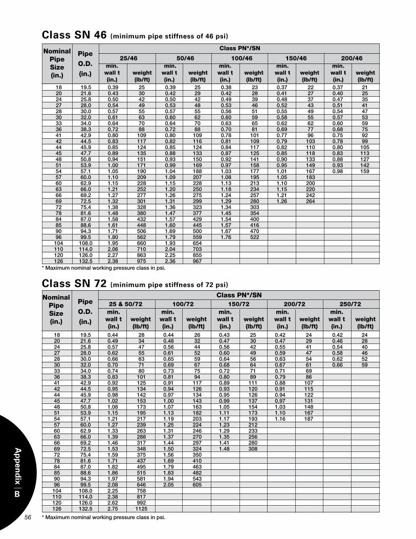
56 57
B
Ap
pen
dix
* Maximum nominal working pressure class in psi.
Class PN*/SN
25/46 50/46 100/46 150/46 200/46Nominal
PipeSize(in.)
Pipe
O.D.
(in.)
Class SN 46 (minimum pipe stiffness of 46 psi)
min. min. min. min. min. wall t weight wall t weight wall t weight wall t weight wall t weight (in.) (lb/ft) (in.) (lb/ft) (in.) (lb/ft) (in.) (lb/ft) (in.) (lb/ft) 18 19.5 0.39 25 0.39 25 0.38 23 0.37 22 0.37 21
20 21.6 0.43 30 0.42 29 0.42 28 0.41 27 0.40 25 24 25.8 0.50 42 0.50 42 0.49 39 0.48 37 0.47 35 27 28.0 0.54 49 0.53 48 0.53 46 0.52 43 0.51 41 28 30.0 0.57 55 0.57 55 0.56 51 0.55 49 0.54 47 30 32.0 0.61 63 0.60 62 0.60 59 0.58 55 0.57 53 33 34.0 0.64 70 0.64 70 0.63 65 0.62 62 0.60 59 36 38.3 0.72 88 0.72 88 0.70 81 0.69 77 0.68 75 41 42.9 0.80 109 0.80 109 0.78 101 0.77 96 0.75 92 42 44.5 0.83 117 0.82 116 0.81 109 0.79 103 0.78 99 44 45.9 0.85 124 0.85 124 0.84 117 0.82 110 0.80 105 45 47.7 0.89 135 0.88 133 0.87 125 0.85 118 0.83 113 48 50.8 0.94 151 0.93 150 0.92 141 0.90 133 0.88 127 51 53.9 1.00 171 0.99 169 0.97 158 0.95 149 0.93 142 54 57.1 1.05 190 1.04 188 1.03 177 1.01 167 0.98 159 57 60.0 1.10 209 1.09 207 1.08 195 1.05 183 60 62.9 1.15 228 1.15 228 1.13 213 1.10 200 63 66.0 1.21 252 1.20 250 1.18 234 1.15 220 66 69.2 1.27 277 1.26 275 1.24 257 1.21 242 69 72.5 1.32 301 1.31 299 1.29 280 1.26 264 72 75.4 1.38 328 1.36 323 1.34 303 78 81.6 1.48 380 1.47 377 1.45 354 84 87.0 1.58 432 1.57 429 1.54 400 85 88.6 1.61 448 1.60 445 1.57 416 90 94.3 1.71 506 1.69 500 1.67 470 96 99.5 1.80 562 1.79 559 1.76 522 104 108.0 1.95 660 1.93 654 110 114.0 2.06 710 2.04 703 120 126.0 2.27 863 2.25 855 126 132.5 2.38 975 2.36 967
min. min. min. min. min. wall t weight wall t weight wall t weight wall t weight wall t weight (in.) (lb/ft) (in.) (lb/ft) (in.) (lb/ft) (in.) (lb/ft) (in.) (lb/ft)
NominalPipeSize(in.)
Pipe
O.D.
(in.)
* Maximum nominal working pressure class in psi.
Class SN 72 (minimum pipe stiffness of 72 psi)
18 19.5 0.44 28 0.44 26 0.43 25 0.42 24 0.42 24 20 21.6 0.49 34 0.48 32 0.47 30 0.47 29 0.46 28 24 25.8 0.57 47 0.56 44 0.56 42 0.55 41 0.54 40 27 28.0 0.62 55 0.61 52 0.60 49 0.59 47 0.58 46 28 30.0 0.66 63 0.65 59 0.64 56 0.63 54 0.62 52 30 32.0 0.70 71 0.69 67 0.68 64 0.67 61 0.66 59 33 34.0 0.74 80 0.73 75 0.72 71 0.71 69 36 38.3 0.83 101 0.81 94 0.80 89 0.79 86 41 42.9 0.92 125 0.91 117 0.89 111 0.88 107 42 44.5 0.95 134 0.94 126 0.93 120 0.91 115 44 45.9 0.98 142 0.97 134 0.95 126 0.94 122 45 47.7 1.02 153 1.00 143 0.99 137 0.97 131 48 50.8 1.08 173 1.07 163 1.05 154 1.03 148 51 53.9 1.15 195 1.13 182 1.11 173 1.10 167 54 57.1 1.21 217 1.19 203 1.17 193 1.16 187 57 60.0 1.27 239 1.25 224 1.23 212 60 62.9 1.33 263 1.31 246 1.29 233 63 66.0 1.39 288 1.37 270 1.35 256 66 69.2 1.46 317 1.44 297 1.41 280 69 72.5 1.53 348 1.50 324 1.48 308 72 75.4 1.59 375 1.56 350 78 81.6 1.71 437 1.69 410 84 87.0 1.82 495 1.79 463 85 88.6 1.86 515 1.83 482 90 94.3 1.97 581 1.94 543 96 99.5 2.08 646 2.05 605 104 108.0 2.25 758 110 114.0 2.38 817 120 126.0 2.62 992 126 132.5 2.75 1125
Class PN*/SN 25 & 50/72 100/72 150/72 200/72 250/72

C
Ap
pen
dix
57
NominalPipeSize(in.)
FWC CouplingNominal Outside Diameter, OD (in.)
Low Flush PN 25 Profile Bell- Pressure PN 50 PN 100 PN 150 PN 200 PN 250 Bell Spigot Relining
18 21.3 21.3 21.3 21.3 21.4 20.4 19.5 20 23.4 23.4 23.4 23.4 23.6 22.5 21.6 24 27.6 27.6 27.6 27.7 27.9 26.8 25.8 27 29.8 29.8 29.8 30.0 30.2 29.0 28.0 28 31.9 31.9 32.0 32.1 32.3 31.0 30.0 30 33.9 33.9 34.0 34.2 34.4 33.0 32.0 33 35.9 35.9 36.1 36.3 35.0 34.0 36 40.2 40.2 40.4 40.6 39.3 38.3 41 44.9 44.9 45.2 45.5 44.0 42.9 42 46.5 46.5 46.8 47.2 45.6 44.5 44 47.9 47.9 48.2 48.6 47.0 45.9 45 49.7 49.7 50.0 50.4 48.8 47.7 48 52.8 52.9 53.2 53.6 51.9 50.8 51 56.0 56.1 56.5 56.8 55.0 53.9 54 59.2 59.4 59.8 60.1 58.2 57.1 57 62.2 62.5 62.8 61.2 60.0 60 65.2 65.5 65.9 64.1 62.9 63 68.3 68.7 69.1 67.2 66.0 66 71.6 72.0 72.4 70.4 69.2 69 74.9 75.4 75.8 73.8 72.5 72 77.9 78.3 76.7 75.4 78 84.2 84.7 82.9 81.6 84 89.6 90.2 88.4 87.0 85 91.4 92.0 90.0 88.6 90 97.1 97.8 95.7 94.3 96 102.5 103.1 101.0 99.5 104 111.1 109.5 108.0 110 117.2 115.5 114.0 120 129.3 127.5 126.0 126 135.8 134.0 132.5
FWC
O.D.’s Plus
0.4
Appendix CJoint Dimensions & Weights
Flush Bell-Spigot
FWC Coupling
Low Profile Bell
Pressure Relining
O.D
O.D O.D
O.D

FWC CouplingNominal Weight (lb.)
PN 25 PN 50 PN 100 PN 150 PN 200 PN 250
Nominal Pipe Size
(in.)
18 25 25 25 25 31 20 28 28 28 35 45 24 43 43 43 46 59 27 46 46 46 62 81 28 50 50 50 59 79 30 53 53 56 66 92 33 56 56 60 73 36 64 64 71 86 41 71 71 86 103 42 74 74 91 138 44 76 76 96 146 45 79 79 101 153 48 84 84 107 161 51 89 96 149 186 54 94 104 167 206 57 100 111 184 60 140 175 212 63 148 189 240 66 155 203 268 69 166 221 294 72 178 238 78 194 256 84 209 294 85 215 305 90 234 341 96 251 377 104 279 110 306 120 355 126 450
58
C
Ap
pen
dix

D
Ap
pen
dix
58 59
Appendix DPipe Material Properties
& Characteristics
Material properties of HOBAS Pipe USA pipes exceed the require-ments of ASTM D3262 for non-pressure applications and of AWWA C950 for pressure service. Actual properties vary depending on pressure and stiffness class. The following range of values covers most pipe constructions. For values specific to individual pipes contact HOBAS Pipe USA.
* Hazen-Williams “C” 155
* Manning’s “n” 0.009
Note 1: Values given are for the reinforced wall (i.e. liner is not included).
E-Modulus1 (106 psi): * Circumferential Flexural * Circumferential Tensile * Axial Tensile Strength1 (103 psi): * Circumferential Tensile * Axial Tensile * Compressive
Thermal Coefficient of LinearExpansion (axial)
PN 50 to 250 1.3 to 2.4 0.5 to 2.8 0.4 to 1.7
7.0 to 33.0 1.4 to 6.4 10.5
in./in./ºF.
PN 0 1.0 to 1.9 – 0.4 to 0.8
– 1.4 to 2.1 10.5
16 x 10-6
Pipe Property Range of Values1
Flow Factors vary somewhat with pipe diameter and flow rate. The following values have been found to be typically representative long-term and are commonly used.

E1 Fiberglass Elbows
Note 1: L may need to be increased if the design pressure exceeds P.
Note 2: Dimensions for other angles or different turning radii are available upon request.
E1 Fiberglass Elbows
Appendix EFitting Dimensions
60
E
Ap
pen
dix
61
DN R L (in.) for P*
(in.) (in.) 11 1/4 º 22 1/2 º 30º 45º 60º 90º (psi) 18 27 18 19 20 25 30 40 200 20 30 18 19 20 26 31 42 175 24 36 20 21 22 28 33 48 27 38 20 21 22 29 34 50 28 40 20 22 23 30 35 52 150 30 42 20 22 23 31 36 54 33 44 20 22 24 32 37 56 36 48 20 22 24 33 39 60 125 41 52 22 23 25 36 42 64 42 54 23 25 26 37 43 66 44 55 23 25 26 37 44 67 100 45 57 23 25 27 38 45 69 48 60 25 25 27 39 46 72 51 63 27 27 28 40 48 75 54 66 28 28 28 41 49 78 57 68 30 30 30 42 50 81 60 70 31 31 31 43 51 84 63 73 33 33 33 44 53 87 66 75 34 34 34 45 54 90 69 78 36 36 36 47 55 93 75 72 80 38 38 38 48 56 96 78 84 41 41 41 51 60 102 84 88 43 43 43 53 63 106 85 90 44 44 44 54 64 108 90 95 47 47 47 57 68 114 96 100 50 50 50 60 72 120 104 108 54 54 54 63 76 126 110 112 57 57 57 66 80 132 120 120 63 63 63 72 88 144 126 126 66 66 66 72 88 144 50
LL
AngleDNØ
Angle
R
L
L
DNØ
L
R
L
Angle
DNØ
Angle < 30°
30° < Angle < 60° 60° < Angle < 90°

61
E2-A Fiberglass Manhole Tee Bases
E2-A Fiberglass Manhole Tee Bases
Notes: 1. Total lay length “L” shown above is typical for (DN1) branch diameter shown. Adjustment to “L” are available.2. All tee bases to be concrete encased to prevent deformations. Concrete design by others.3. Complete manhole design by others to include allowance for transfer of surface loads (HS-20) away from branch (DN1).4. “H” dimension shown is typical, it can be adjusted to allow for specific encasement heights, service laterals, FRP riser connections with FWC couplings, etc.5. Configurations shown (DN x DN1) can be adjusted to meet specific designs.6. DN1 can change but must be less than or equal to DN for all tee base configurations.7. Above dimensions are for straight thru (180 deg.) configurations. Tee bases with angles (PI’s) are available, with increased L
DN DN11 L H DN11 L H DN11 L H (in.) (in.) (in.) (in.) (in.) (in.) (in.) (in.) (in.) (in.) 30 24 54 15 30 60 15 30 60 15 33 24 54 15 30 60 15 30 60 15 36 24 54 15 36 78 15 36 78 15 41 24 54 15 36 78 15 36 78 15 42 24 54 15 36 78 15 36 78 15 44 24 54 15 36 78 15 36 78 15 45 24 54 15 36 78 15 36 78 15 48 24 54 15 36 78 15 48 108 15 51 24 54 15 36 78 15 48 108 15 54 24 54 15 36 78 15 48 108 15 57 24 78 15 36 78 15 48 108 15 60 24 78 15 36 78 15 48 108 15 63 24 78 15 36 78 15 48 108 15 66 24 78 15 36 78 15 48 108 15 69 24 78 15 36 78 15 48 108 15 72 24 78 15 36 78 15 48 108 15 78 24 78 15 36 78 15 48 108 15 84 24 108 15 36 108 15 48 108 15 85 24 108 15 36 108 15 48 108 15 90 24 108 15 36 108 15 48 108 15 96 24 108 15 36 108 15 48 108 15 104 24 108 15 36 108 15 48 108 15 110 24 108 15 36 108 15 48 108 15 120 24 114 15 36 114 15 48 114 15 126 24 114 15 36 114 15 48 114 15
E
Ap
pen
dix
Elevation ViewElevation View
DN
DN1
L
H

62 63
E
Ap
pen
dix
E2-B Fiberglass Lateral Tees
E2-B Fiberglass Lateral Tees
Note 1: Dimensions for other combinations of DN and DN 1 are available upon request.Note 2: Dimensions shown are typical, but custom tees are routinely available.
DN DN11 L H DN11 L H DN11 L H (in.) (in.) (in.) (in.) (in.) (in.) (in.) (in.) (in.) (in.) 18 18 57 30 - - - - - - 20 20 60 30 18 60 30 - - - 24 24 66 33 20 66 33 18 63 33 27 27 68 34 24 67 34 20 64 34 28 28 70 35 24 68 35 20 65 35 30 30 72 36 24 69 36 20 66 36 33 33 75 38 30 72 38 24 66 38 36 36 81 40 30 75 40 24 69 40 41 41 87 44 36 81 44 30 75 44 42 42 90 45 36 84 45 30 78 45 44 44 93 46 42 86 46 36 80 46 45 45 96 47 42 87 47 36 81 47 48 48 99 48 42 90 48 36 84 48 51 51 102 51 48 99 51 42 93 51 54 54 108 54 48 102 54 42 96 54 57 57 111 56 54 105 56 48 99 56 60 60 114 57 54 108 57 48 102 57 63 63 117 59 60 111 59 54 105 59 66 66 120 60 60 114 60 54 108 60 69 69 123 62 66 120 62 60 114 62 72 72 126 63 66 120 63 60 114 63 78 78 138 69 72 132 69 66 126 66 84 84 141 70 78 135 70 72 129 70 85 85 144 72 78 138 72 72 132 72 90 90 150 75 84 144 75 78 138 75 96 96 156 78 90 150 78 84 144 78 104 104 168 84 96 162 84 90 156 84 110 110 180 90 104 174 90 96 168 90 120 120 192 96 110 180 96 104 174 96 126 126 198 99 120 192 99 110 180 99
Plan ViewPlan View
DN
DN1
L
H

63
E
Ap
pen
dix
Note 1: Dimensions for other combinations of DN and DN 1 are available upon request.Note 2: L may need to be increased if the design pressure exceeds P.
E3 Fiberglass Reducers
E3 Fiberglass Reducers
DN DN11 L DN11 L DN11 L DN11 L P (in.) (in.) (in.) (in.) (in.) (in.) (in.) (in.) (in.) (psi)
20 18 48 - - - - - - 24 20 54 18 57 - - - - 27 24 54 20 60 18 63 - -
250
28 24 54 20 60 18 63 - - 30 24 57 20 63 18 66 - - 33 30 54 24 63 20 69 18 72 36 30 57 24 66 20 72 18 75 41 36 57 30 66 24 75 20 81
200
42 36 57 30 66 24 75 20 81 44 36 60 30 69 24 78 20 84 45 42 54 36 63 30 72 24 81 175 48 42 57 36 66 30 75 24 84 51 48 54 42 63 36 72 30 81 54 48 57 42 66 36 75 30 84 57 54 60 48 63 42 72 36 81
150
60 54 63 48 66 42 75 36 84 63 60 66 54 66 48 72 42 81 66 60 69 54 69 48 75 42 84 69 66 72 60 72 54 72 48 81
125
72 66 75 60 75 54 75 48 84 78 72 81 66 81 60 81 54 84 84 78 87 72 87 66 87 60 87 85 78 90 72 90 66 90 60 90
100
90 84 96 78 96 72 96 66 96 96 90 99 84 99 78 99 72 99 104 96 108 90 108 84 108 78 108 75
110 104 114 96 114 90 114 85 114 120 110 126 104 126 96 126 90 126 126 120 132 110 132 104 132 96 132
50

64 65
E
Ap
pen
dix
MinimumL
(in.)
Number Bolt Bolt 0f Circle Diameter Bolts Diameter (in.) (in.) (in.)
Minimum Bolt
Hole Diam-eter (in.)
DN(in.)
MinimumO.D. of Flange
(in.)
E4 Fiberglass Flanges
E4 Fiberglass Flanges
18 24 25.00 16 22.75 1.125 1.250 20 30 27.50 20 25.00 1.125 1.250 24 30 32.00 20 29.50 1.250 1.375 27 32 34.25 24 31.75 1.250 1.375 28 34 36.50 28 34.00 1.250 1.375 30 36 38.75 28 36.00 1.250 1.375 36 36 46.00 32 42.75 1.500 1.625 41 40 50.75 36 47.25 1.500 1.625 42 42 53.00 36 49.50 1.500 1.625 48 48 59.50 44 56.00 1.500 1.625 54 48 66.25 44 62.75 1.750 1.875 60 48 73.00 52 69.25 1.750 1.875 66 48 80.00 52 76.00 1.750 1.875 72 48 86.50 60 82.50 1.750 1.875 78 48 93.00 64 89.00 2.000 2.125 84 48 99.75 64 95.50 2.000 2.125 90 48 106.50 68 102.00 2.250 2.375 96 48 113.25 68 108.50 2.250 2.375 104 48 120.00 72 114.50 2.500 2.625 110 48 126.75 72 120.75 2.500 2.625 120 48 140.25 76 132.75 2.75 2.875 126 48 147.0 80 139.25 3.00 3.125
Note 1: Flange drilling dimensions are according to AWWA C207 Class D (150 psi) and ANSI B16.1 (125 psi)Note 2: Fiberglass reinforced polymer flanges are available for non-pressure and some pressure applications. Protected ductile iron, fusion bonded epoxy coated steel or stainless steel flanges may be used at any pressure.
L
DNØ

Appendix FCorrosion Resistance Guide
65
F
Ap
pen
dix
IntroductionThe following guide is a compilation of corrosion resistance information obtained from resin manu-facturers and actual test results on our pipe. The recommendations are believed to represent acceptable continuous environments for satisfactory long-term pipe performance, however, individual project conditions should be considered when selecting the appropriate product construction. Also, pressure and stiffness ratings may be reduced at elevated temperatures. It is our intention to assist the design engineer as much as possible in making these evaluations.
ChemicalsChemicals not listed on the following pages have probably not been tested with our pipe materials by the date of this publication. Contact us for new information.
TemperatureThe recommended maximum temperature given is not always the absolute maximum acceptable service temperature. It is the highest temperature at which a resin or product has been tested, used or evaluated. A product may be suitable for higher temperature operation, but additional information or testing would be required in order to establish such performance.
Coupling GasketsThe standard FWC coupling gasket material is an
elastomeric compound. It exhibits superior chemical and temperature resistance and it is suitable for a wide variety of environments including sanitary sewage, water, salt water, many acids, bases, salts and other chemicals. Some types of gaskets may be sensitive to some chemicals such as some hydrocarbons and many chlorinated and aromatic solvents.
Alternate gasket materials may be available for these situations. We would be pleased to assist you in the selection of an appropriate gasket material and in the establishment of specific limitations for temperature and concentration based on your individual application.
Abbreviations & SymbolsStd. (Standard) - Std. refers to our standard pipe constructed with thermosetting polyester resins.
VE (Vinyl Ester) - VE refers to HOBAS pipes constructed using thermosetting vinyl ester resins.
NR (Not Recommended) - Product of this construction is not recommended for continuous service in this environment. However, it may be suitable at a lower concentration or for intermittent exposure.
- (Dash) - This symbol indicates no data is currently available.
AAcetaldehyde All NR NRAcetic Acid 0-25 — 150 25-50 — 150 50-75 — —Acetic Anhydride All NR NRAcetone 100 NR NRAcrylic Acid 25 — 100Acrylonitrile All NR NRAlcohol, Butyl All NR —Alcohol, Ethyl 10 80 150 100 — —Alcohol, Isopropyl 10 80 150 100 NR —Alcohol, Methyl 10 NR — 100 NR NRAlcohol, Methyl Isobutyl 10 NR 150
Alcohol, Secondary Butyl 10 NR 150Allyl Chloride All NR NRAlum All 100 180Aluminum Chloride All 100 180Aluminum Fluoride All — 80Aluminum Hydroxide All NR 150Aluminum Nitrate All 100 150Aluminum Potassium Sulfate All 90 180Ammonia, Aqueous 0-20 NR 140Ammonia, Gas NR 100Ammonia, Liquid NR NRAmmonium Bicarbonate 0-50 NR 150Ammonium Bisulfite All — 150Ammonium Carbonate All NR 150
ChemicalConcentration % By Weight
MaximumRecommendedTemperature ºF.
Std. VE ChemicalConcentration % By Weight
MaximumRecommendedTemperature ºF.
Std. VE

66 67
F
Ap
pen
dix
ChemicalConcentration % By Weight
MaximumRecommendedTemperature ºF.
Std. VE ChemicalConcentration % By Weight
MaximumRecommendedTemperature ºF.
Std. VE
Ammonium Chloride All 90 180Ammonium Citrate All — 150Ammonium Fluoride All — 150Ammonium Hydroxide 5 NR 150 10 NR 150 20 NR 150 29 NR 100Ammonium Nitrate All 90 180Ammonium Persulfate All NR 180Ammonium Phosphate 65 90 180Ammonium Sulfate All 90 180Amyl Acetate 100 NR NRAniline All NR NRAniline Hydrochloride All — 150Aniline Sulfate All NR 180Arsenious Acid All — —
BBarium Acetate All NR 180Barium Carbonate All NR 180Barium Chloride All 100 180Barium Hydroxide 0-10 NR 150Barium Sulfate All 90 180Barium Sulfide All NR 180Beer 80 120Benzene 100 NR NR5% Benzene in Kerosene — —Benzene Sulfonic Acid All NR 180Benzoic Acid All — 180Benzyl Alcohol 100 NR NRBenzyl Chloride 100 NR NRBlack Liquor Recovery, (furnace gasses) NR —Bromine, Liquid NR NRBromine, Water 5 NR —Butyl Acetate 100 NR NRButyric Acid 0-50 — — 100 NR —
CCadmium Chloride All — 180Calcium Bisulfite All — 180Calcium Carbonate All NR 180Calcium Chlorate All — 180Calcium Chloride All 100 180Calcium Hydroxide All NR 180Calcium Hypochlorite All NR 160Calcium Nitrate All 100 180Calcium Sulfate All 90 180Calcium Sulfite All — 180
Cane Sugar Liquor All — 180Caprylic Acid 100 — 180Carbon Dioxide 100 — 180Carbon Disulfide NR NRCarbon Monoxide (gas) 100 180Carbon Tetrachloride 100 NR —Carbon Acid — —Carbowax — — —Castor Oil — 180Carboxy Methyl Cellulose 10 — 150Chlorinated Brine Liquors — — (caustic chlorine cell)Chlorinated Wax All — 180Chlorine Dioxide/Air 15 NR —Chlorine Dioxide, Wet Gas Satd. NR 180Chlorine, Dry Gas 100 NR 180Chlorine, Wet Gas 100 NR 180Chlorine, Liquid NR NRChlorine Water All NR —Chloracetic Acid 25 NR — 50 NR — Con. NR NRChlorobenzene 100 NR NRChloroform 100 NR NRChlorosulfonic Acid 100 NR NRChromic Acid 20 NR — 30 NR NRChromium Sulfate All — —Citric Acid All 100 180Coconut Oil — 180Copper Chloride All 100 180Copper Cyanide All NR 180Copper Fluoride All NR 180Copper Nitrate All 100 180Copper Sulfate All 100 180Corn Oil — 180Corn Starch Slurry — 180Corn Sugar All — 180Cottonseed Oil — 180Cresylic Acid 100 NR NRCrude Oil, Sour 100 80 180Crude Oil, Sweet 100 80 180Cyclohexane 100 NR —Cyclohexanone 100 NR —

67
F
Ap
pen
dix
ChemicalConcentration % By Weight
MaximumRecommendedTemperature ºF.
Std. VE ChemicalConcentration % By Weight
MaximumRecommendedTemperature ºF.
Std. VE
DDetergents, Sulfonated All — —Dialfyl Phthalate All — —Di-Ammonium Phosphate 65 — 180Dibromophenol 100 NR NRDibutyl Ether 100 — —Dichloro Benzene 100 NR NRDichloroethylene 100 NR NRDichloromonomethane 100 NR NRDichloropropane 100 NR NRDichloropropene 100 NR NRDiesel Fuel 100 90 180Diethanol Amine 100 — —Diethyl Amine 100 NR NRDiethyl Benzene 100 NRDiethyl Carbonate 100 NR NRDiethylene Glycol 100 — —Diethylhexyl Phosphoric Acid (in Kerosene) 20 — 120Diethyl Sulfate 100 NR NRDiisopropanol Amine 100 — —Dimethyl Formamide 100 NR NRDimethyl Morpholine 100 NR NRDimethyl Phthalate 100 NR —Dioctyl Phthalate 100 NR —Dipropylene Glycol 100 — —
EElectrosol 5 — 150Epichlorohydrin 100 NR NREpoxidized Soybean Oil 100 — 150Ethyl Acetate 100 NR NREthyl Acrylate 100 NR NREthyl Benzene 100 NR NREthyl Bromide 100 NR NREthyl Chloride 100 NR NREthyl Ether 100 NR NREthylene Glycol All 90 180Ethyl Sulfate 100 — —
FFatty Acids All — 180Ferric Chloride All 100 180Ferric Nitrate All 100 180Ferric Sulfate All 100 180Ferrous Chloride All 100 180Ferrous Nitrate All 100 180
Ferrous Sulfate All 100 180Flue Gas — —Fluoboric Acid All 80 180Fluosilisic Acid 10 80 180 20 — 160Formaldehyde All — —Formic Acid 10 70 180 All NR 100Freon ll — —Fuel Oil 100 90 180Furfural 5 — — 10 — — 100 NR NR
GGas, Natural — 180Gluconic Acid 50 — 180Glucose All 100 180Glycerine All 90 180Gold Plating Solution: — 180 63% Potassium Ferrocyanide .2% Potassium Gold Cyanide .8% Sodium Cyanide
HHeptane — 150Hexane — 150Hexylene Glycol — 150Hydraulic Fluid — 180Hydrazine NR NRHydrochloric Acid 0-20 NR 180 20-37 NR 160Hydrochloric Acid saturated with Chlorine gas 30 NR —Hydrocyanic Acid All — 180Hydrofluoric Acid 10 NR 150 20 NR 100Hydrofluosilicic Acid 10 — 180Hydrogen Bromide Wet Gas 100 — 180Hydrogen Chloride Dry Gas 100 — 180Hydrogen Chloride Wet Gas 100 — 180Hydrogen Peroxide 0-30 NR 150Hydrogen Sulfide, Dry All 100 180Hydrogen Sulfide, Aqueous All 100 180Hydrogen Fluoride, Vapor — 180

68 69
F
Ap
pen
dix
Hydrosulfite Bleach — 180Hypochlorous Acid 10 — 180 20 NR 150
lIsopropyl Amine All — 100Isopropyl Palmitate 100 — 180
KKerosene — 180
LLactic Acid All — 180Lasso* (50% Chlorobenzene) NR NRLatex All — —Laurel Chloride 100 — 180Lauric Acid All — 180Lead Acetate All — 180Lead Nitrate All — 180Levulinic Acid All — 180Linseed Oil — 180Lithium Bromide All — 180Lithium Sulfate All — 180
MMagnesium Bisulfite All — 180Magnesium Carbonate All — 180Magnesium Chloride All 100 180Magnesium Hydroxide All NR 180Magnesium Sulfate All 100 180Maleic Acid All — 180Mercuric Chloride All 100 180Mercurous Chloride All 80 180Methylene Chloride 100 NR NRMethyl Ethyl Ketone 100 NR NRMethyl Isobutyl Carbitol 100 NR NRMethyl Isobutyl Ketone 100 NR NRMethyl Styrene 100 NR NRMineral Oils 80 180Monochloro Acetic Acid 100 NR NRMonoethynolamine 100 NR NRMotor Oil — — 180Myristic Acid 100 — 180
NNaphtha 100 — 180Naphthalene 100 — 180Nickel Chloride All 100 180
Nickel Nitrate All 100 180Nickel Chloride All 100 180Nickel Nitrate All 100 180Nickel Plating — 180 8% Lead .8% Fluoboric Acid .4% Boric AcidNickel Plating — 180 11% Nickel Sulfate 2% Nickel Chloride 1% Boric AcidNickel Plating — 180 44% Nickel Sulfate 4% Ammonium Chloride 4% Boric AcidNickel Sulfate All 100 180Nitric Acid 5 NR 150 20 NR 120 52 NR NRNitric Acid Fumes — — 160Nitrobenzene 100 NR NR
OOakite Rust Stripper — 180Octanoic Acid 100 — 180Oil, Sour Crude 100 80 180Oil, Sweet Crude 100 80 180Oleic Acid All NR 180Oleum (Fuming Sulfuric) NR NROlive Oil 100 — 180Oxalic Acid All — 180
PPerchloretylene 100 NR 100Perchloric Acid 10 NR 150 30 NR 100Peroxide Bleach NR 180 2% Sodium Peroxide 96% .025% Epsom Salts, 5% Sodium Silicate, 42° BE 1.4% Sulfuric Acid, 66°BEPhenol 100 NR NRPhenol Sulfonic Acid 100 NR NRPhosphoric Acid All 100 180Phosphoric Acid Fumes 100 180Phosphorous Pentoxide 0-54 — 180Phosphorous Trichloride 100 NR NRPhthalic Acid All — 180
ChemicalConcentration % By Weight
MaximumRecommendedTemperature ºF.
Std. VE ChemicalConcentration % By Weight
MaximumRecommendedTemperature ºF.
Std. VE

69
F
Ap
pen
dix
Pickling Acids Sulfuric and Hydrochloric NR 180Picric Acid/ Alcoholic 10 NR 180Polyvinyl Acetate Latex All — 180Polyvinyl Alcohol 100 NR 120Polyvinyl Chloride Latex with 35 parts DOP — 120Potassium Alum Sulfate All 90 180Potassium Bicarbonate 0-50 NR 150Potassium Bromide All 90 180Potassium Carbonate All NR 150Potassium Chloride All 100 180Potassium Dichromate All — 180Potassium Ferricyanide All — 180Potassium Ferrocyanide All — 180Potassium Hydroxide All NR 150Potassium Nitrate All 100 180Potassium Permanganate All NR 180Potassium Persulfate All — 180Potassium Sulfate All 100 180Propionic Acid 20 — 180 50 — 160 100 — NRPropylene Glycol All — 180Pyridine 100 — NR
SSalicylic Acid All — 160Sebacic Acid All — 180Selenius Acid All — 180Silver Nitrate All — 180Soaps All 90 180Sodium Acetate All — 180Sodium Aluminate All NR 120Sodium Alkyl Aryl Sulfonates All — 150Sodium Benzoate 100 — 180Sodium Bicarbonate All NR 180Sodium Bifluoride All — 120Sodium Bisulfate All 80 180Sodium Bisulfite All 70 180Sodium Bromate 10 — —Sodium Bromide All 90 180Sodium Carbonate 0-25 NR — 35 NR —Sodium Chlorate All NR 180Sodium Chloride All 100 180Sodium Chlorite All NR 150Sodium Chromate 50 — 180
Sodium Cyanide All — 180Sodium Dichromate All — 180Sodium Di-Phosphate All — 180Sodium Ferricyanide All — 180Sodium Ferrocyanide All — 180Sodium Fluoride All — 180Sodium Fluoro Silicate All — 150Sodium Hexametaphosphates All — 120Sodium Hydroxide 5 NR 150 10 NR 150 25 NR 120 50 NR 160Sodium Hydrosulfide All — 180Sodium Hypochlorite 0-5 70 180 5-15 NR 150Sodium Lauryl Sulfate All — 180Sodium Mono-Phosphate All 100 180Sodium Nitrate All 100 180Sodium Nitrite All 100 180Sodium Persulate 20 — 130Sodium Silicate All NR 180Sodium Sulfate All 100 180Sodium Sulfide All NR 180Sodium Sulfite All NR 180Sodium Tetro Borate All — 180Sodium Thiocyanate 57 — 180Sodium Thiosulfate All — 180Sodium Tripolyphosphate All — 180Sodium Xylene Sulfonate All NR 180Sorbitol Solutions All — 150Sour Crude Oil 100 80 180Soya Oil All — 180Stannic Chloride All — 180Stannous Chloride All — 180Stearic Acid All 100 180Styrene 100 NR NRSugar, Beet and Cane Liquor All — 180Sugar, Sucrose All — 180Sulfamic Acid 0-25 70 180Sulfanilic Acid All — 180Sulfated Detergents All 100 180Sulfur Dioxide, Dry or Wet NR —Sulfur Trioxide/Air All NR 180
ChemicalConcentration % By Weight
MaximumRecommendedTemperature ºF.
Std. VE ChemicalConcentration % By Weight
MaximumRecommendedTemperature ºF.
Std. VE

70
F
Ap
pen
dix
Sulfuric Acid 0-5 100 180 5-70 — 160 75 NR — Over 75 NR NR
Sulfurous Acid All NR —Superphosphoric Acid NR 180 105% H3PO3
76% P20s
TTall Oil All — —Tannic Acid All — —Tartaric Acid All NR 180Tetrachloroethylene 100 NR NRThionyl Chloride 100 NR NRToluene 100 NR NRToluene Solfonic Acid All — 180Transformer Oils: Mineral Oil Types — 180 Chloro-Phenyl Types NR NRTrichlor Acetic Acid 50 NR 180Trichloroethane 100 NR —Trichloroethylene 100 NR NRTrichlorophenol 100 NR NRTridecylbenzene Sulfonate All — 180Trimethylene Chlorobromide 100 NR NR
Trisodium Phosphate All NR 180Turpentine 100 NR —Tween Surfactant All — 150
VVegetable Oils 100 180Vinegar 100 180Vinyl Acetate 100 NR NRVinyl Toluene 100 NR —
WWater Deionized NR 180 Demineralized 100 180 Distilled 100 180 Fresh 100 180 Salt 100 180 Sea 100 180
XXylene 100 NR NR
ZZinc Chlorate All — 180Zinc Chloride All 100 180Zinc Nitrate All 100 180Zinc Sulfate All 100 180
ChemicalConcentration % By Weight
MaximumRecommendedTemperature ºF.
Std. VE ChemicalConcentration % By Weight
MaximumRecommendedTemperature ºF.
Std. VE

G
Ap
pen
dix
Appendix GDeflected Pipe Minimum
Inside Diameters
Pressure Class PN 25 PN 50 PN 100 Min. Dia (in.) Min. Dia (in.) Min. Dia (in.)
PipeO.D.(in.)
NominalPipe Size
(in.) @ 3% defl. @ 5% defl. @ 3% defl. @ 5% defl. @ 3% defl. @ 5% defl. 18 19.5 18.21 17.83 18.23 17.85 18.23 17.85
20 21.6 20.20 19.79 20.20 19.79 20.20 19.79 24 25.8 24.15 23.66 24.18 23.68 24.18 23.68 27 28 26.23 25.69 26.25 25.71 26.25 25.71 28 30 28.13 27.55 28.13 27.55 28.15 27.57 30 32 30.01 29.39 30.03 29.41 30.03 29.41 33 34 31.91 31.25 31.91 31.25 31.93 31.27 36 38.3 35.95 35.21 35.97 35.23 35.99 35.25 41 42.9 40.29 39.46 40.31 39.48 40.33 39.50 42 44.5 41.81 40.94 41.83 40.96 41.85 40.98 44 45.9 43.12 42.23 43.14 42.25 43.16 42.27 45 47.7 44.83 43.90 44.85 43.92 44.87 43.94 48 50.8 47.75 46.77 47.77 46.79 47.79 46.81 51 53.9 50.68 49.63 50.70 49.65 50.72 49.67 54 57.1 53.70 52.59 53.72 52.61 53.74 52.63 57 60 56.43 55.27 56.45 55.29 56.47 55.31 60 62.9 59.16 57.94 59.20 57.98 59.23 58.00 63 66 62.09 60.81 62.13 60.85 62.15 60.87 66 69.2 65.11 63.77 65.15 63.81 65.17 63.83 69 72.5 68.23 66.82 68.25 66.84 68.29 66.88 72 75.4 70.96 69.50 71.00 69.54 71.02 69.56 78 81.6 76.81 75.23 76.86 75.27 76.88 75.29 84 87 81.91 80.22 81.95 80.26 81.99 80.30 85 88.6 83.42 81.70 83.46 81.74 83.50 81.78 90 94.3 88.81 86.98 88.85 87.02 88.89 87.06 96 99.5 93.71 91.78 93.75 91.82 93.79 91.86 104 108 101.73 99.63 101.77 99.67 101.81 99.71 110 114 107.39 105.17 107.41 105.19 107.45 105.23 120 126 118.70 116.25 118.72 116.27 118.76 116.31 126 132.5 124.84 122.27 124.86 122.29 124.90 122.33
Class SN 18
Pressure Class PN 25 PN 50 PN 100 PN 150 PN 200 Min. Dia (in.) Min. Dia (in.) Min. Dia (in.) Min. Dia (in.) Min. Dia (in.)
NominalPipeSize(in.)
Pipe
O.D.
(in.) @ 3% @ 5% @ 3% @ 5% @ 3% @ 5% @ 3% @ 5% @ 3% @5% defl. defl. defl. defl. defl. defl. defl. defl. defl. defl.
Class SN 36
71
18 19.5 18.08 17.71 18.08 17.71 18.11 17.73 18.11 17.73 18.13 17.75 20 21.6 20.04 19.63 20.06 19.65 20.06 19.65 20.08 19.67 20.10 19.69 24 25.8 23.99 23.50 23.99 23.50 24.01 23.52 24.01 23.52 24.03 23.54 27 28 26.04 25.51 26.04 25.51 26.06 25.53 26.09 25.55 26.11 25.57 28 30 27.92 27.35 27.92 27.35 27.94 27.37 27.96 27.39 27.98 27.41 30 32 29.78 29.17 29.80 29.19 29.82 29.21 29.84 29.23 29.86 29.25 33 34 31.66 31.01 31.68 31.03 31.70 31.05 31.72 31.07 31.74 31.09 36 38.3 35.69 34.95 35.71 34.97 35.73 34.99 35.75 35.01 35.77 35.03 41 42.9 40.01 39.18 40.01 39.18 40.03 39.20 40.07 39.24 40.09 39.26 42 44.5 41.50 40.64 41.52 40.66 41.54 40.68 41.56 40.70 41.60 40.74 44 45.9 42.82 41.93 42.82 41.93 42.86 41.97 42.88 41.99 42.92 42.03 45 47.7 44.50 43.58 44.52 43.60 44.54 43.62 44.58 43.66 44.60 43.68 48 50.8 47.41 46.43 47.43 46.45 47.45 46.47 47.49 46.51 47.51 46.53 51 53.9 50.31 49.27 50.33 49.29 50.35 49.31 50.39 49.35 50.43 49.39 54 57.1 53.31 52.21 53.31 52.21 53.35 52.25 53.40 52.29 53.44 52.33 57 60 56.03 54.87 56.05 54.89 56.07 54.91 56.11 54.95 60 62.9 58.74 57.53 58.76 57.55 58.80 57.59 58.84 57.63 63 66 61.64 60.37 61.66 60.39 61.70 60.43 61.76 60.49 66 69.2 64.64 63.31 64.66 63.33 64.70 63.37 64.75 63.41 69 72.5 67.74 66.35 67.76 66.37 67.78 66.39 67.84 66.45 72 75.4 70.45 69.00 70.47 69.02 70.52 69.06 78 81.6 76.26 74.69 76.28 74.71 76.33 74.75 84 87 81.32 79.64 81.34 79.66 81.38 79.70 85 88.6 82.81 81.10 82.83 81.12 82.89 81.18 90 94.3 88.16 86.34 88.18 86.36 88.24 86.42 96 99.5 93.04 91.12 93.06 91.14 93.12 91.20 104 108 101.00 98.91 101.02 98.93 101.08 98.99 110 114 106.61 104.41 106.63 104.43 106.69 104.49 120 126 117.85 115.42 117.89 115.46 117.95 115.52 126 132.5 123.95 121.39 123.99 121.43 124.05 121.49

72
G
Ap
pen
dix
Pressure Class PN 25 PN 50 PN 100 PN 150 PN 200 Min. Dia (in.) Min. Dia (in.) Min. Dia (in.) Min. Dia (in.) Min. Dia (in.)
NominalPipeSize(in.)
Pipe
O.D.
(in.) @ 3% @ 5% @ 3% @ 5% @ 3% @ 5% @ 3% @ 5% @ 3% @ 5% defl. defl. defl. defl. defl. defl. defl. defl. defl. defl.
18 19.5 18.02 17.65 18.02 17.65 18.04 17.67 18.06 17.69 18.06 17.69 20 21.6 19.98 19.57 20.00 19.59 20.00 19.59 20.02 19.61 20.04 19.63 24 25.8 23.91 23.42 23.91 23.42 23.93 23.44 23.95 23.46 23.97 23.48 27 28 25.96 25.43 25.98 25.45 25.98 25.45 26.00 25.47 26.02 25.49 28 30 27.84 27.27 27.84 27.27 27.86 27.29 27.88 27.31 27.90 27.33 30 32 29.70 29.09 29.72 29.11 29.72 29.11 29.76 29.15 29.78 29.17 33 34 31.58 30.93 31.58 30.93 31.60 30.95 31.62 30.97 31.66 31.01 36 38.3 35.59 34.85 35.59 34.85 35.63 34.89 35.65 34.91 35.67 34.93 41 42.9 39.89 39.06 39.89 39.06 39.93 39.10 39.95 39.12 39.99 39.16 42 44.5 41.38 40.52 41.40 40.54 41.42 40.56 41.46 40.60 41.48 40.62 44 45.9 42.69 41.81 42.69 41.81 42.71 41.83 42.76 41.87 42.80 41.91 45 47.7 44.36 43.44 44.38 43.46 44.40 43.48 44.44 43.52 44.48 43.56 48 50.8 47.26 46.29 47.28 46.31 47.30 46.33 47.35 46.37 47.39 46.41 51 53.9 50.15 49.12 50.17 49.13 50.21 49.17 50.25 49.21 50.29 49.25 54 57.1 53.15 52.06 53.17 52.08 53.19 52.10 53.23 52.14 53.29 52.19 57 60 55.86 54.71 55.88 54.73 55.90 54.75 55.96 54.81 60 62.9 58.57 57.37 58.57 57.37 58.61 57.41 58.68 57.47 63 66 61.46 60.19 61.48 60.21 61.52 60.25 61.58 60.31 66 69.2 64.44 63.11 64.46 63.13 64.50 63.17 64.56 63.23 69 72.5 67.54 66.15 67.56 66.17 67.60 66.21 67.66 66.27 72 75.4 70.23 68.78 70.27 68.82 70.31 68.86 78 81.6 76.04 74.47 76.06 74.49 76.10 74.53 84 87 81.07 79.40 81.09 79.42 81.16 79.48 85 88.6 82.57 80.86 82.59 80.88 82.65 80.94 90 94.3 87.89 86.08 87.93 86.12 87.97 86.16 96 99.5 92.75 90.84 92.77 90.86 92.83 90.92 104 108 100.69 98.61 100.73 98.65 100.79 98.71 110 114 106.29 104.10 106.33 104.14 106.39 104.20 120 126 117.50 115.08 117.54 115.12 117.60 115.18 126 132.5 123.58 121.03 123.62 121.07 123.68 121.13
Class SN 46
Pressure Class PN 25 & 50 PN 100 PN 150 PN 200 PN 250 Min. Dia (in.) Min. Dia (in.) Min. Dia (in.) Min. Dia (in.) Min. Dia (in.)
NominalPipeSize(in.)
Pipe
O.D.
(in.) @ 3% @ 5% @ 3% @ 5% @ 3% @ 5% @ 3% @ 5% @ 3% @ 5% defl. defl. defl. defl. defl. defl. defl. defl. defl. defl.
18 19.5 17.92 17.55 17.92 17.55 17.94 17.57 17.96 17.59 17.96 17.59 20 21.6 19.86 19.45 19.88 19.47 19.90 19.49 19.90 19.49 19.92 19.51 24 25.8 23.77 23.28 23.79 23.30 23.79 23.30 23.81 23.32 23.83 23.34 27 28 25.80 25.27 25.82 25.29 25.84 25.31 25.86 25.33 25.88 25.35 28 30 27.66 27.09 27.68 27.11 27.70 27.13 27.72 27.15 27.74 27.17 30 32 29.52 28.91 29.54 28.93 29.56 28.95 29.58 28.97 29.60 28.99 33 34 31.38 30.73 31.40 30.75 31.42 30.77 31.44 30.79 36 38.3 35.36 34.63 35.40 34.67 35.42 34.69 35.44 34.71 41 42.9 39.64 38.82 39.66 38.84 39.70 38.88 39.72 38.90 42 44.5 41.13 40.28 41.15 40.30 41.17 40.32 41.21 40.36 44 45.9 42.43 41.55 42.45 41.57 42.49 41.61 42.51 41.63 45 47.7 44.09 43.19 44.14 43.23 44.16 43.24 44.20 43.28 48 50.8 46.98 46.01 47.00 46.03 47.04 46.07 47.08 46.11 51 53.9 49.84 48.82 49.88 48.86 49.92 48.90 49.95 48.92 54 57.1 52.83 51.74 52.87 51.78 52.91 51.82 52.93 51.84 57 60 55.52 54.37 55.56 54.41 55.60 54.45 60 62.9 58.21 57.01 58.25 57.05 58.29 57.09 63 66 61.09 59.83 61.13 59.87 61.17 59.91 66 69.2 64.05 62.73 64.09 62.77 64.15 62.83 69 72.5 67.11 65.73 67.17 65.79 67.21 65.83 72 75.4 69.80 68.36 69.86 68.42 78 81.6 75.57 74.01 75.61 74.05 84 87 80.59 78.92 80.65 78.98 85 88.6 82.06 80.36 82.12 80.42 90 94.3 87.36 85.56 87.42 85.62 96 99.5 92.18 90.28 92.24 90.34 104 108 100.08 98.02 100.16 98.10 110 114 105.63 103.46 105.72 103.54 120 126 116.79 114.38 116.87 114.46 126 132.5 122.83 120.29 122.91 120.37
Class SN 72

R14 10/2015
1413 E. Richey Rd.Houston, Texas 77073281-821-2200www.hobaspipe.com