The COMPLETE GUIDE TO HIGH-PERFORMANCE … · return must carry a ZEOS Return Merchandise...
77
R User’s Guide The COMPLETE GUIDE TO HIGH-PERFORMANCE COMPUTING WITH YOUR PANTERA COMPUTER
Transcript of The COMPLETE GUIDE TO HIGH-PERFORMANCE … · return must carry a ZEOS Return Merchandise...

R
User’s Guide
The
COMPLETE
GUIDE TO
HIGH-PERFORMANCE
COMPUTING
WITH YOUR
PANTERA
COMPUTER

2
Copyright 1994ZEOS InternationalAll rights reserved
Words by John HartnettIllustrations by Steve Scofield
Cover Design by MaryLou Ziebarth
Limitation of remedies and liabilities:
ZEOS’ entire liability and customers’ exclusive and sole remedy for damages from any cause whatsoever(including without limitation any nonperformance, misrepresentation, or breach of warranty) shall be limited toreturning the products pursuant to the thirty (30) day satisfaction guarantee, or to repair or replace specificproducts or services that do not comply with the limited warranty given by ZEOS. Any products or servicesrepaired or replaced by ZEOS pursuant to this paragraph shall be warranted as of the date of delivery inaccordance with the terms and conditions herein for the duration of the one-year term of Limited Warrantygiven by ZEOS. In no event will ZEOS be liable for any damages caused, in whole or in part, by customer, orfor any economic loss, physical injury, lost revenues, lost profits, lost savings or other indirect, incidental,special or consequential damages incurred by any person, even if ZEOS has been advised of the possibility ofsuch damage for claims.
Some states do not allow the exclusion or limitation of incidental or consequential damages for consumerproducts, and some states do not allow limitations on how long an implied warranty lasts, so the abovelimitations or exclusions may not apply to you.
This warranty gives you specific legal rights, and you may also have other rights which vary from state to state.
ZEOS provides no warranties whatsoever on software.
ZEOS International, Ltd. shall not be held liable for technical or editorial omissions or errors made herein; norfor incidental or consequential damages resulting from furnishing, performance, or use of this material. Thisdocument contains proprietary information protected by copyright. No part of this document may bephotocopied or reproduced by mechanical, electronic, or other means in any form without prior writtenpermission of ZEOS International, Ltd.
Trademark AcknowledgmentsAdaptec is the trademark of Adaptec, Inc.IBM, XT, AT, and OS/2 are registered trademarks of International Business Machines Corporation.UNIX is a trademark of AT&T Laboratories.Phoenix is the trademark of Phoenix Technologies Ltd.Quadtel is the trademark of Quadtel Corp., A Phoenix Technologies Ltd. Co.Intel, 486SX, DX, DX2, and Pentium are trademarks of Intel Corporation.XENIX, MS-DOS, GW-Basic, OS/2, Windows, and Microsoft are trademarks of Microsoft Corporation.
All other brand and product names are trademarks or registered trademarks of their respective companies.

3
Customer Assurance Program
Thirty (30) Day Satisfaction Guarantee on CertainProducts.
Any product (except for software, software disks, relateddocumentation and consumables) purchased from ZEOS may bereturned within thirty days from the date it was shipped by ZEOS fora full refund of the purchase price excluding original shipping charges.
Returned products must be in as new condition, in original packing,complete with all warranty cards, manuals, cables and other materialsas originally shipped; not modified or damaged.
Any returned product must be shipped prepaid and insured. Anyreturn must carry a ZEOS Return Merchandise Authorization (RMA)number, obtained from ZEOS, on the outside of each carton. Returnswithout RMA numbers will not be accepted. After thirty days fromshipment, all sales are final and credit or refunds will not be given.

4
ZEOS Computer Systems One Year LimitedWarranty
All new ZEOS computer systems come with a One Year LimitedWarranty which provides that the products ZEOS manufactures orassembles, other than items such as software, disks and relateddocumentation, will remain in good working condition, free fromdefects in material and workmanship under normal use and service,for a period of one year from the date of shipment from ZEOS. Thiswarranty is limited to the original purchaser and is not transferable.During this one year period, ZEOS will repair or replace, at its option,any defective product or parts at no additional charge to the customer,provided that the defective product or part is returned, shipmentprepaid, to ZEOS. All replaced products and parts become theproperty of ZEOS. Replacement parts shall be similar new orserviceable used parts. This Limited Warranty does not extend to anyproducts which have been damaged as a result of accident, misuse,abuse (such as incorrect voltages, power surges, improper orinsufficient ventilation, failure to follow ZEOS’ provided operatinginstructions, “acts of God” or other situations beyond the control ofZEOS), or as the result of service or modification by anyone otherthan ZEOS. Non-ZEOS installed parts or components are notcovered, nor is damage to ZEOS provided components covered as aresult of their installation. This warranty does not cover workperformed by others, all warranty work must be performed by ZEOS.

5
FCC Compliance Statement
For U.S. and Canadian Users
Danger!Changes or modifications to this unit not expressly approved by the party responsible forcompliance could void the user’s authority to operate the equipment.
This equipment has been tested and found to comply with the limits for a Class B digitaldevice, pursuant to Part 15, Subpart B of the FCC Rules. These limits are designed toprovide reasonable protection against harmful interference in a residential installation.This equipment generates, uses and can radiate radio frequency energy and, if notinstalled and used in accordance with the instructions, may cause harmful interferenceto radio communications.
However, there is no guarantee that interference will not occur in a particularinstallation. If this equipment does cause harmful interference to radio or televisionreception, which can be determined by turning the equipment on and off, the user isencouraged to try to correct the interference by one or more of the following measures.
♦Reorient or relocate the receiving antenna.
♦Increase the separation between the equipment and receiver.
♦Connect the equipment into an outlet on a circuit different from that to which the receiver is needed.
♦Consult the dealer or an experienced radio/TV technician for help.
The connection of a non-shielded equipment interface cable to this equipment willinvalidate the FCC Certification of this device and may cause interference levels whichexceed the limits established by the FCC for this equipment.
This equipment is a Class B digital apparatus which complies with the RadioInterference Regulations, C.R.C., c. 1374.
Cet appareil numèrique de la classe B est conformè au Règlement sur le brouillageradioèlèctrique, C.R.C., ch. 1374.

6

7
Contents1. The Big Picture ....................................................................... 10
Desktop System At A Glance .................................................. 12Vertical System At A Glance .................................................... 14How to Open a Desktop Case................................................. 16How to Open a Vertical Case .................................................. 18Inside a Desktop System Unit ................................................. 20Inside a Vertical System Unit .................................................. 21
2. The Mainboard........................................................................ 22
Mainboard Features ................................................................ 22PCI Local Bus 32-Bit High Speed Expansion Slots .............................. 23Secondary Cache Subsystem ............................................................. 23Keyboard Selectable Speed ................................................................ 23Serial Port .......................................................................................... 24On-Board Peripherals ......................................................................... 24Parallel Port ........................................................................................ 25SCSI Port ........................................................................................... 25Business Audio Ports .......................................................................... 25
Mainboard Connectors............................................................ 26Mainboard Diagram ................................................................ 27Mainboard Jumpers ................................................................ 28
FLASH1.............................................................................................. 28CLR1 .................................................................................................. 28
Mainboard Jumpers Diagram.................................................. 29
3. Using SETUP .......................................................................... 31
Main Menu .............................................................................. 32Main Menu Options ................................................................. 33
System Time....................................................................................... 33System Date ....................................................................................... 33Diskette Drive A: ................................................................................. 33Diskette Drive B: ................................................................................. 33Daylight Savings ................................................................................. 33Video System ..................................................................................... 33System Memory ................................................................................. 34Extended Memory .............................................................................. 34

8
Contents
Fixed Disk Menu ..................................................................... 34Fixed Disk 0 Type ............................................................................... 35Fixed Disk 1 - 3 Control ..................................................................... 35
SCSI BIOS Enable Menu ........................................................ 36Memory Control ...................................................................... 38
External Cache ................................................................................... 38Cache Video BIOS area ...................................................................... 38Idt 7MP6157 256K Module: ................................................................. 38DRAM speed ...................................................................................... 38
Memory Shadow ..................................................................... 39System Shadow.................................................................................. 39Video Shadow..................................................................................... 39Shadow Memory Regions ................................................................... 39
Boot Sequence Menu ............................................................. 40Keyboard Auto-repeat Rate ................................................................. 40Keyboard Auto-repeat Delay ............................................................... 40Key Click ............................................................................................ 40Numlock ............................................................................................. 40Summary screen ................................................................................ 40Floppy Check ..................................................................................... 41Floppy Swap....................................................................................... 41Boot Sequence ................................................................................... 41SETUP prompt ................................................................................... 41POST errors ....................................................................................... 41
Advanced Menu ...................................................................... 42Integrated Peripherals ......................................................................... 42PCI Devices........................................................................................ 43
Security ................................................................................... 44Set Supervisor Password .................................................................... 44Set User Password ............................................................................. 44Password on Boot .............................................................................. 45Diskette Access .................................................................................. 45Fixed disk boot sector ......................................................................... 45System Backup Reminder................................................................... 45Virus Check Reminder ........................................................................ 45
Exit Menu ................................................................................ 45

9
4. How to Add an Expansion Board.......................................... 46
5. How Disk Drives Work ........................................................... 48
How a Floppy Drive Works...................................................... 49How an IDE Hard Drive Works................................................ 50How a CD-ROM Drive Works.................................................. 51
6. How to Add System RAM....................................................... 52
Installing SIMMs...................................................................... 54
7. How to Add System Cache Memory ..................................... 56
8. How to Install an Optional SCSI Controller Chip................. 58
Hardware ................................................................................ 58Software .................................................................................. 61
9. Special Notes on the Pantera 90 ........................................... 62
Mainboard Specifications.......................................................... 65
Mainboard Environmental Specifications ................................ 659-Pin Serial Port (J4) Pin Assignment ..................................... 6625-Pin Serial Port (J3) Pin Assignment ................................... 66Parallel Port (J2) Pin Assignment ............................................ 68SCSI Port Pin Assignment ...................................................... 70
Handy Cheat Sheet .................................................................... 71
Glossary ...................................................................................... 73
Contents
10
1. The Big Picture
Chapter 1 - The Big Picture
Welcome to the ZEOS User’s Guide! The User’s Guide workswith the Before Calling ZEOS Technical Support guide and theGetting Started manual to help keep your system running troublefree, year after year.
The User’s Guide is divided into nine chapters.
Chapter 1, The Big Picture , gives an overview of a typicaldesktop and vertical system. It also shows the major componentsinside the system unit case.
Chapter 2, The Mainboard , gives detailed information aboutyour mainboard.
Chapter 3, Using SETUP , explains how to use the built-inSETUP features of your BIOS to configure your system.
Chapter 4, How to Add an Expansion Board , shows how toadd or change video adapter cards, controller cards, internalmodems, and anything else that uses the expansion slots.
Chapter 5, How Disk Drives Work , shows how to connect afloppy drive, IDE hard drive, or CD-ROM drive.
Chapter 6, How to Add System RAM , shows how to addmemory SIMMs.
Chapter 7, How to Add System Cache Memory , shows howto increase your system cache to improve CPU throughput.

11
Chapter 1 - The Big Picture
Chapter 8, How to Install an Optional SCSI ControllerChip, shows how to add a SCSI chip and connect SCSI devicesto the mainboard.
Chapter 9, Special Notes on the Pantera 90, describes specialfeatures of the 90 MHz Pantera system.
Mainboard Specifications lists technical details about yourmainboard.
The Handy Cheat Sheet gives a short summary of some of themost needed or most forgotten commands.
The Glossary gives short definitions of common computerterms.
12
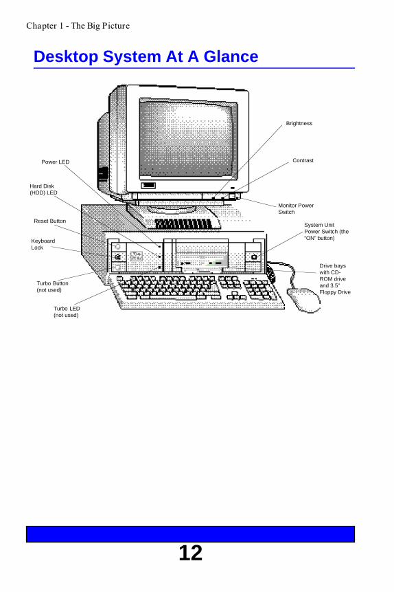
Desktop System At A Glance
Chapter 1 - The Big Picture
Reset Button
Power LED
Brightness
Contrast
Hard Disk(HDD) LED
System UnitPower Switch (the“ON” button)
Drive bayswith CD-ROM driveand 3.5”Floppy Drive
Monitor PowerSwitch
Turbo LED(not used)
Turbo Button(not used)
KeyboardLock
13
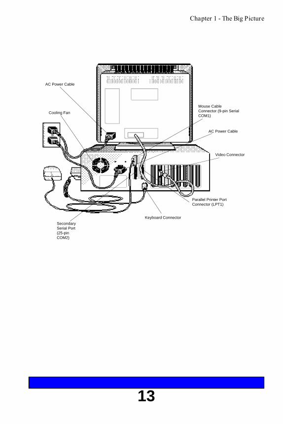
Chapter 1 - The Big Picture
Cooling Fan
Parallel Printer PortConnector (LPT1)
AC Power Cable
SecondarySerial Port(25-pinCOM2)
Keyboard Connector
Video Connector
AC Power Cable
Mouse CableConnector (9-pin SerialCOM1)
14
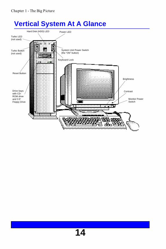
Vertical System At A Glance
Chapter 1 - The Big Picture
Reset Button
Drive bayswith CD-ROM driveand 3.5”Floppy Drive
Turbo LED(not used)
Hard Disk (HDD) LED Power LED
Turbo Button(not used)
System Unit Power Switch(the “ON” button)
Keyboard Lock
Brightness
Contrast
Monitor PowerSwitch

15
Chapter 1 - The Big Picture
AC PowerCable
Mouse CableConnector(9-pin SerialCOM1)
Cooling Fan
SecondarySerial Port(25-pinCOM2)
Keyboard Connector
AC Power Cable
VideoConnector
Parallel PrinterPort Connector(LPT1)

16
How to Open a Desktop Case
The figures show the plastic bezel, screw locations, and covermotion for a desktop case.
Chapter 1 - The Big Picture
Caution:Whenever you open the case or work inside the computer there is danger ofelectrostatic discharge. Electrostatic discharge can permanently damageyour equipment. Always ground yourself by touching the system cabinetbefore touching any internal component. We strongly recommend using anantistatic wrist strap attached to cabinet ground.
To open a desktop case:
1. Turn off the monitor and system unit power. Unplug the ACpower cables and disconnect any other cables attached tothe back of the system unit.
2. Remove the plastic bezel from the back of the case bypulling it away from the case.
3. Unscrew the five mounting screws at the back of the casethat hold the case cover to the system unit chassis.
4. Slide the case cover back and up. Be careful not to snag anycables or connectors inside the case.
5. Set the case cover aside while you work on your system.
6. When through, reattach the case cover, screws, bezel, andcables in the reverse order.

17
Chapter 1 - The Big Picture
Cover
Chassis
Plastic Bezel
Mounting Screws

18
How to Open a Vertical Case
The figures show the plastic bezel, screw locations, and covermotion for a vertical case.
Chapter 1 - The Big Picture
Caution:Whenever you open the case or work inside the computer there is danger ofelectrostatic discharge. Electrostatic discharge can permanently damageyour equipment. Always ground yourself by touching the system cabinetbefore touching any internal component. We strongly recommend using anantistatic wrist strap attached to cabinet ground.
Opening a vertical case is almost identical to opening a desktopcase.
To open a vertical case:
1. Turn off the monitor and system unit power. Unplug the ACpower cables and disconnect any other cables attached tothe back of the system unit.
2. Remove the plastic bezel from the rear of the case by pullingit away from the case.
3. Unscrew the six mounting screws at the back of the casethat hold the case cover to the system unit chassis.
4. Slide the case cover back and up. Be careful not to snag anycables or connectors inside the case.
5. Set the case cover aside while you work on your system.
6. When through, reattach the case cover, screws, bezel, andcables in the reverse order.

19
Plastic Bezel
Cover
Chassis
Mounting Screws
Chapter 1 - The Big Picture

20
Inside a Desktop System Unit
Chapter 1 - The Big Picture
The figure below shows some of the most common componentsinside the system unit case.
CPU
Floppy Drives, CD-ROMDrives, and TapeBackup Units
Hard Disk Drive
Power Supply
Expansion Boards
Mainboard
Expansion Slots
The mainboard is the large circuit board at the bottom of thesystem unit case. It is the heart of your system. All of the othercomponents inside the case work for the mainboard. The powersupply delivers electricity to the mainboard. The disk drives,keyboard connectors, and other parts of the system unit bringinformation to and from the mainboard.

21
Inside a Vertical System Unit
CPU
Floppy Drives, CD-ROMDrives, and TapeBackup Units
Chapter 1 - The Big Picture
Vertical systems have all the same components as desktopsystems. The figure shows the mainboard and commoncomponents inside a vertical system unit case.
Hard Disk Drive
Mainboard
Expansion Slots
Expansion Boards
Power Supply

22
2. The MainboardThe mainboard is the large circuit board located at the bottomof the system unit case. It is the heart of your computer system.This board contains the central processing unit (CPU),secondary cache subsystem, expansion slots, ports andconnectors for other computer components, and the system mainmemory or RAM.
Your mainboard includes:
♦Intel Pentium (TM) Processor running at 60Mhz, 66Mhz, or 90 Mhz
♦Small Computer System Interface (SCSI) host adapter socket
♦Optional 256K or 512K secondary system cache
♦Integrated Windows compatible Business Audio that supportsADPCM compression
♦Integrated floppy drive controller
♦Two local bus IDE hard drive interface ports supporting up to 4 IDEdevices
♦Enhanced Parallel Port
♦Two full-function, RS232, 16550-compatible serial ports
♦High-speed system memory; expandable from 2MB to 192MB
♦Flash BIOS; relocatable to 32-bit high-speed RAM for fasterperformance
♦Five 16-bit ISA expansion slots
♦Three 32-bit PCI, local bus, high-speed expansion slots
♦Clock/calendar with on-board battery backup
Mainboard Features
Chapter 2 - The Mainboard

23
Chapter 2- The Mainboard
PCI Local Bus 32-Bit High Speed Expansion Slots
The three PCI local bus, high speed expansion slots moveinformation at up to 133 MB/s. This provides an extremely highperformance, 32-bit interface to support high speed, local busvideo adapter cards and other peripherals such as LAN adaptersand hard disk drives.
Secondary Cache Subsystem
The secondary cache subsystem enhances the performance of theCPU. The integrated cache controller and a cache memorySIMMs provide the secondary cache subsystem for the system.Either one 256K Cache SIMM or one 512K cache SIMMprovides the cache memory.
Keyboard Selectable Speed
You can increase system performance by activating Turbo modewith the keyboard.
<Ctrl><Alt><+> activates turbo mode (default).<Ctrl><Alt><-> disables turbo mode.
Note: Some Pantera systems have a Turbo LED and Turbo button on thefront of the case. The Turbo button and Turbo LED are not used onPantera systems. Only the keyboard command enables or disablesturbo mode.

24
Chapter 2 - The Mainboard
On-Board Peripherals
Your mainboard has all of the standard peripheral interfaces andmany extras built in. This eliminates the need for manyperipheral expansion cards and greatly enhances systemreliability.
The integrated peripheral interfaces include:
♦Optional SCSI port (supports both SCSI-1 and -2 type devices)
♦Two serial ports
♦Parallel port
♦Floppy drive controller
♦Two IDE hard drive controller ports each capable of controlling twohard drives
♦Business audio with speaker output jack, alternate internalspeaker output, and microphone input jack
Serial Port
Your mainboard has two RS232C asynchronous serial ports,which are generally referred to as COM1 (9-pin) and COM2(25-pin) ports. The serial ports are used to attach mice, serialprinters, modems, or other serial peripheral devices. Both serialports are 16550 UART compatible for higher data transfer rates.You can install up to two additional serial ports (COM3 andCOM4) simultaneously in your system. However, MS-DOS doesnot manage more than two COM ports simultaneously very well.Therefore, while you can install and use four COM ports, do notattempt to use more than two at the same time or you may runinto problems. Specifically, you should not try to use COM1 andCOM3 at the same time, or COM2 and COM4 at the same time.
25
Chapter 2 - The Mainboard
Parallel Port
The 25-pin Centronics parallel port is often called the printerport because it is generally used only for printers. However, theparallel interface has achieved a high level of standardization.The parallel port is also EPP or Enhanced Parallel Portcompatible. This means you can use the port to connect otherperipheral devices designed to use a Centronics parallelinterface.
SCSI Port
The optional on-board SCSI host adapter allows you to connectand control up to seven peripheral devices such as SCSI-compatible disk drives, tape backup units, communicationsdevices, and CD-ROM drives.
The SCSI port is a parallel, multitasking interface whichsupports both SCSI-1 and SCSI-2 devices.
The SCSI port is configured from the system SETUP program.For SCSI system setup parameters, refer to the SCSI ControlMenu in Using SETUP.
Business Audio Ports
The on-board business audio adapter chip allows you to use abuilt-in external speaker jack and microphone input jack for full-featured audio support of many popular software packages. Theexternal speaker jack and microphone input jack are mounted ona bracket at the back of the system unit.
26
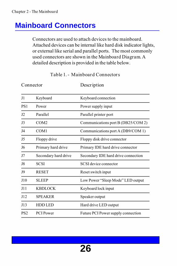
Mainboard Connectors
Connectors are used to attach devices to the mainboard.Attached devices can be internal like hard disk indicator lights,or external like serial and parallel ports. The most commonlyused connectors are shown in the Mainboard Diagram. Adetailed description is provided in the table below.
Table 1. - Mainboard Connectors
J1 Keyboard Keyboard connection
PS1 Power Power supply input
J2 Parallel Parallel printer port
J3 COM2 Communications port B (DB25/COM 2)
J4 COM1 Communications port A (DB9/COM 1)
J5 Floppy drive Floppy disk drive connector
J6 Primary hard drive Primary IDE hard drive connector
J7 Secondary hard drive Secondary IDE hard drive connection
J8 SCSI SCSI device connector
J9 RESET Reset switch input
J10 SLEEP Low Power “Sleep Mode” LED output
J11 KBDLOCK Keyboard lock input
J12 SPEAKER Speaker output
J13 HDD LED Hard drive LED output
PS2 PCI Power Future PCI Power supply connection
Connector Description
Chapter 2 - The Mainboard

27
Mainboard Diagram
Chapter 2 - The Mainboard
SIMM socketfor systemcache
PentiumCPU socket
Resetbuttonheader
Keyboard Lockheader
Alternateinternalspeakerconnector
Main sound chipsocket
SIMMsockets forsystem RAM
FLASHprotectjumper
Low PowerLED hearer Internal
Spakerheader
Hard diskLEDheader
CPU fanpowerconnector Speaker
output jackAudio boardcable connector
Mic. Input
Audio boardcableconnector
PAL soundchip
Primary IDEHDD headerJ6
Secondary IDEHDD headerJ7
SCSI chipsocket
Floppydriveheader
SCSIheader
COM1serial portJ4
CoM2serial portJ3
MainboardPowerConnector
Paralllel portconnectorJ2
Clock/Battery
PCI PowerSupply socket3.2Volts Keyboard
connectorJ1
16-bit ISAexpansion slots
ClearCMOSMemoryjumper
32-bit PCIexpansionslots

28
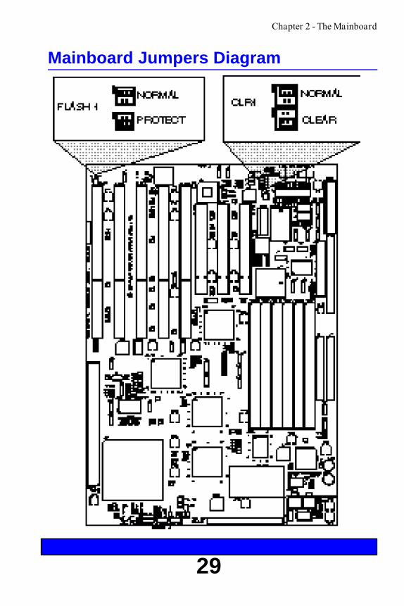
Mainboard JumpersJumpers are small groups of pins that can be connected ordisconnected with jumper caps. To connect a jumper, place thejumper cap over the pins you wish to connect and gently pressdown.
The Pantera mainboard uses only two jumpers. The mainboardstores most configurations in battery backed CMOS memory.The Pantera mainboard uses the SETUP program to reconfigureoptions stored in battery backed memory. The Panteramainboard also uses the FLASH programming utility to updatethe system BIOS. Other mainboards use jumpers to configureupgrade options and parameters directly on the board. ThePantera mainboard uses the SETUP program and the FLASHprogramming utility instead, making upgrades and changes fastand easy.
FLASH1The FLASH1 jumper allows or disallows re-programming ofthe FLASH BIOS with the FLASH utility program. The defaultor normal position is to allow programming with the FLASHprogram.
CLR1The CLR1 jumper holds or resets the CMOS battery backedSETUP memory. You should not clear the CMOS SETUPmemory unless it becomes corrupted and cannot bereprogrammed with the SETUP program. To clear the CMOSmemory, turn off system power , then momentarily place thejumper in the CLEAR position, then return the jumper to theNORMAL position. Your system will not operate with thejumper in the CLEAR position, so be sure to return the CLR1jumper to the NORMAL position.
Chapter 2 - The Mainboard
29
Mainboard Jumpers Diagram
Chapter 2 - The Mainboard

30

31
3. Using SETUP
The Extended BIOS Software System consists of severalprograms which work along with the system BIOS. Together,they provide additional system customization. You can accessthe Extended BIOS Main Menu by pressing F2 during systemboot. Use the arrow keys to highlight and select the utility andthen press Enter.
The Main Menu allows you to choose between:
♦Main Menu options
♦Advanced System Setup
♦Security
♦Exit
Each of the main screens allows you to choose several sub-menus. You navigate through the Extended BIOS softwareusing the cursor keys and several function keys. You can alsoload the original factory default settings from ROM, load thecurrent settings from battery backed CMOS, or save newchanges to CMOS. Press F1 at any time for help.
To make changes to SETUP values, use the arrow keys to selectthe desired item. The selected item will be highlighted. The +and - keys allow you to scroll through the available options.Only items surrounded by square brackets may be changed.Press F9 to load the SETUP defaults from ROM. Press F10 toload your previous settings from CMOS. Exit through the Exitmenu. Press Enter to see a sub-menu, Esc to return to theprevious menu.
Chapter 3 - Using SETUP
32
Main Menu
Your system setup has been configured at the factory formaximum performance and reflects all options you may haveordered. Generally, you need to run SETUP only if you changeyour system’s hardware configuration, such as installing adifferent hard drive, or if the on-board battery fails.
The SETUP Main Menu allows you to change:
♦Time and date
♦Video System
♦System memory configuration
♦Floppy drive types
The Main Menu also offers you the following sub-menus:
♦Fixed Disk 0-3 Type
♦SCSI BIOS Enable
♦Memory Control
♦Memory Shadow
♦Boot Sequence
Chapter 3 - Using SETUP

33
Main Menu Options
System TimeSets the real-time clock, using a 24-hour format. During thepower-up sequence, the real time is read and saved in memoryfor use by the operating system. After boot up, the operatingsystem updates the system time.
System DateSets the real-time date for month, day, and year. During thepower-up sequence, this information is read and saved inmemory for use by the operating system to determine thecurrent date. After completing the power-up sequence, theoperating system updates the current date.
Diskette Drive A:Specifies the size and capacity of the floppy-disk drive installedas drive A. Options are: 360K, 720K, 1.2M, 1.44M, and 2.88M
Diskette Drive B:Specifies the size and capacity of the floppy-disk drive installedas drive B.
Daylight SavingsAllows the system clock to adjust automatically for daylightsavings time. The default is enabled.
Video SystemThis option can be set to one of the following:
♦Monochrome
♦80 column Color Graphics (CGA 80 x 25)
♦Enhanced Graphics Adapter or VGA (EGA/VGA)(default)
Chapter 3 - Using SETUP

34
Main Menu Options
System MemorySets the system memory size. This is set to 640KB at the ZEOSfactory. MS-DOS can manage conventional memory of 640KBwithout additional software. You should not need to change thisvalue.
Extended MemoryDefines the size of extended memory in 64K increments.Extended memory is the total amount of memory not used asSystem Memory and for Shadow RAM (384K is allocated forShadow RAM).
For example, a system with 2MB (2048KB) installed (BIOSshadowed) will indicate 1024KB of extended memory [i.e.:2048KB - (640KB + 384KB) = 1024KB].
Chapter 3 - Using SETUP
Fixed Disk MenuThe Fixed Disk Menu lists each of the installed IDE hard/fixeddisks. Your first, or primary hard drive is Fixed Disk 0. If youhave additional hard drives installed or want to install moredrives, they will be configured as Fixed Disk 1, 2, or 3.

35
Fixed Disk 0 TypeSets the hard drive 0 configuration. This option was set to Autoat the ZEOS factory prior to shipment. In most cases, thisoption is all you need. When Auto is selected, the systemdetermines what kind of hard drive is installed and displays thedrive parameters.
Note: Only change this option setting if you change your hard drive.
Multi-Sector TransferDetermines the number of sectors per block for multiple sectortransfers. Options are Disabled, 2, 4, 8, and 16. The default is16. Older hard drives (and even some newer drives) will notwork properly if the number of sectors is set too high.
LBA Mode ControlEnables or disables Logical Block Addressing, allowing you touse large IDE hard drives. This must be enabled for IDE harddrives greater than 528 MB.
Physical DriveDetermines the physical address of the drive. Options are :Default, Primary Master, Primary Slave, Secondary Master, andSecondary Slave. The default is Default.
Fixed Disk 1 - 3 ControlIf your system has more hard drives installed, again set theseoptions to Auto. This sets the drive type for the additional harddrives. Never needlessly change the default setting.
Chapter 3 - Using SETUP
36
SCSI BIOS Enable Menu
The SCSI default configuration settings are appropriate formost system installations. Configuration changes are onlynecessary when using nonstandard (older) SCSI devices ornonstandard peripheral expansion cards.
SCSI BIOS EnabledEnables or disables the integrated SCSI BIOS.
Controller AddressThe on-board SCSI controller always uses IRQ11, non-DMA.If other attached devices are using IRQ11, change their settingsto a different IRQ. The SCSI I/O port default address is 340h(primary). The alternate address is 140h, but is not supportedby the system BIOS at this time.
SynchronousThis parameter selects whether synchronous data transfer withSCSI targets should be initiated. When disabled, the system willstill respond to negotiations initiated by SCSI targets. Thisoption is generally used when an older SCSI device is installedwhich doesn’t recognize synchronous negotiation. The defaultis enabled.Note: Some SCSI devices like CD-ROM drives may require this parameter
to be disabled.
Chapter 3 - Using SETUP
37
EnhancedEnable this option if you are using a hard drive larger than1GByte. This option enables enhanced mode disk geometrytranslation. If the BIOS detects a drive capacity greater than1GByte, it uses 255 head/ 63 sector translation. Otherwise ituses 64 head/ 32 sector translation. This option also allows forhigher synchronous transfer rates of 6.67 MBytes/sec. or 10MBytes/sec.
ParityEnables parity checking by the on-board SCSI controller. Parityis supported by most SCSI devices. If this option is disabled,the SCSI controller still generates parity, but no interrupt willbe generated on parity errors.
DisconnectEnables a SCSI device to disconnect from the on-boardcontroller if it will take a long time to complete a requestedoperation, and later reconnect when ready to finish. Use thisfeature to improve bus use in multitasking environments. Singletask environments like DOS usually work smoother when thisoption is disabled. However, some tape backup units willoperate better when this option is enabled, even under DOS.The default is disabled.
Chapter 3 - Using SETUP
38
Memory Control
The memory control sub-menu allows you to make detailedchanges to your system memory configuration.
External CacheThis option permits you to enable or disable the external cachememory. Some applications are not compatible with caching.This option allows you to disable memory caching, if necessary.
Cache Video BIOS areaThis option controls caching of the video BIOS. Enabling thisoption could improve video performance. The default isenabled.Note: Not implemented on all systems.
Idt 7MP6157 256K Module:or Motorola MCM67A618 512K
Selects Dual Write Enable Mode for the external system cachemodule. Set this to TRUE if you are using a 256K Idt modulewith a 7MP6157 part number or if you are using a 512KMotorola module with an MCM67A618 part number.
DRAM speedAlways set the DRAM speed to the slowest speed of all yourinstalled memory SIMMs. Your mainboard supports 60ns or70ns memory chips.Note: Not implemented on all systems.
Chapter 3 - Using SETUP

39
Memory Shadow
Shadowing is the technique of mirroring or copying portions ofthe computer’s slower, read-only memory into much fastersystem memory. Shadowing key portions of memory generallyimproves system performance.
System ShadowSystem shadow is always enabled.
Video ShadowEnables or disables copying of the video BIOS into RAM.Shadowing the video BIOS may improve your video responsetime. The default is enabled.
Shadow Memory RegionsAllows you to choose which specific memory regions will beshadowed. The default is for all specific regions disabled.
Chapter 3 - Using SETUP

40
The boot sequence sub-menu allows you to speed up boot timeby disabling certain standard computer boot procedures.
Keyboard Auto-repeat RateDefines the rate the keyboard repeats when a key is pressed andheld. The number displayed represents the number ofrepetitions per second the keyboard will generate. The default is30 times per second.
Keyboard Auto-repeat DelayDefines time delay between the time a key is depressed and thetime the key begins to repeat. The default is 1/2 second.
Key ClickWhen selected, provides an audible feedback whenever a key ispressed.
NumlockThis option defines how the Num Lock key should work onpower up. The Num Lock key is used to determine whether thecursor keys or the numeric keys are active on the keypad.Normally, the BIOS sets the Num Lock (numeric keys active) ifthe system detects a compatible keyboard on power up.
Auto Sets the Num Lock (numeric keys active) if the systemdetects a compatible keyboard on power up (default)
On Selects the numeric keys regardless of the keyboardOff Selects the cursor movement keys regardless of the keyboard
Boot Sequence Menu
Chapter 3 - Using SETUP
Summary screenDuring normal boot, the system BIOS displays a summaryscreen of your computer configuration at boot. Disabling thesystem summary screen at boot skips this display.

41
Floppy CheckWhen enabled the system checks that each floppy driveconfigured in CMOS memory is operational. Disabling floppycheck skips this step, speeding up boot time.
Floppy SwapFor systems that boot using DOS, allows you to swap the drivedesignation for floppy drives A: and B:. Enabled swaps thedrives. Disabled uses the drives as they are installed.Note: Not implemented on all systems.
Boot SequenceDuring boot the computer looks for an operating system storedon the floppy boot drive or logical drive C on an installed harddrive. Disk drive boot sequence determines which drive ischecked first. The default is [A: then C:], meaning the systemwill check floppy drive A first, then if no operating system ispresent, it will look on drive C. If you normally boot from thehard disk C, setting this option to [C: then A:] or [C: only] willspeed your boot time.
SETUP promptWhen enabled, the system displays the message “Press F2 toenter SETUP” on boot. When disabled this step is skipped onboot.
POST errorsWhen enabled, the system pauses whenever it finds an errorduring bootup and displays the message “Press F1 to continueor F2 to enter SETUP”. When disabled the system ignoresPOST errors during boot. The default is enabled.
Chapter 3 - Using SETUP

42
Advanced Menu
Warning!Setting these items incorrectly could disable your system. Never needlesslychange from the defaults.
The Advanced Menu offers the following options:
Large Disk DOS CompatibilityEnables or Disables Logical Block Addressing, enabling you touse very large IDE hard drives.Note: Not implemented on all systems.
Integrated PeripheralsThis menu allows you to set the addresses, interrupts and DMAchannels for your serial, parallel, and audio ports.
Com Port A:When either Com Port 1 or Com Port 2 is set to Auto, thesystem will automatically set the interrupts for both ports.Otherwise this option allows you to set the interrupt and I/Oaddress of the COM1 serial port.
Com Port B:When either Com Port 1 or Com Port 2 is set to Auto, thesystem will automatically set the interrupts for both ports.Otherwise this option allows you to set the interrupt and I/Oaddress of the COM2 serial port.
Chapter 3 - Using SETUP

43
Parallel PortSets the parallel port designation. The default setting of Autoallows the system to automatically assign the first availableparallel port designation to the on-board parallel port (usuallyLPT1). Otherwise allows you to specify the parallel portaddress.
ModeAllows you to specify the parallel port as Uni-directional(default) or Bi-directional.
Audio PortSets the interrupt and DMA access for the audio port. Thedefault is IRQ9, DMA 6. You may also choose IRQ9 withDMA 5, or IRQ11 with DMA 5 or 6. The port can also bedisabled.
Note: The on-board SCSI controller will automatically use IRQ11. If youuse both the SCSI controller and the audio port, be sure the audioport is set to IRQ9.
PCI DevicesThe PCI Devices sub-menu allows you to set specifications forthe PCI bus and for PCI devices connected to the bus. If you areinserting a PCI controller card into one of your PCI slots, thisscreen allows you to set the interrupt for the slot. The top rowof the table at the bottom of the screen explains which of thefour steering interrupts (0 through 3) needs an interrupt entry.For example, a card inserted in PCI slot 6 needs an interruptentered on Interrupt Steering Register 0.
Note: For more help setting PCI bus master interrupts, call ZEOSTechnical Support at 1-800-228-5390.
Chapter 3 - Using SETUP

44
Security
The system security options allow you to password-protectsystem access. Whenever a password is entered, you must re-enter the proper password to access the system.
To protect yourself from forgetting your passwords, we stronglyrecommend writing them down and storing for safekeeping.
Warning!If you forget the password, your system will not operate. You will haveto completely clear the CMOS memory and re-enter your entire systemconfiguration. Write down your password and store it in a safe place.
The following security items are available:
♦Set Supervisor Password
♦Set User Password
♦Password on Boot
♦Diskette Access
♦Fixed disk boot sector
♦System Backup Reminder
♦Virus Check Reminder
Set Supervisor PasswordAllows you to enter a system supervisor password.
Set User PasswordAllows you to enter a system user password. You can onlyenter a user password if a supervisor password is also entered.
Chapter 3 - Using SETUP

45
Password on BootWhen enabled, the system asks you for a password on boot.The system will only boot if the correct supervisor or userpassword is entered. The default is disabled.
Diskette AccessSpecifies which level of password is required to access thefloppy drives. This option prevents unauthorized copying ofinformation. The default is Supervisor.
Fixed disk boot sectorWhen enabled, write protects the boot sector on your hard driveto protect against viruses.
System Backup ReminderWhen enabled, displays boot reminder message to back up yoursystem every day, week, or month. The default is disabled.
Virus Check ReminderWhen enabled, displays boot reminder message to scan forviruses every day, week, or month. The default is disabled.
Exit Menu
Offers Exit and Save options for the SETUP program.
Chapter 3 - Using SETUP

46
4. How to Add an ExpansionBoard
The expansion slots on your mainboard are designed to accept awide variety of cards or boards. Components such as scanners,tape backup units, video capture devices, and many others useexpansion cards (also called expansion boards) to communicatewith the CPU on the mainboard. Often adding these componentsis as easy as opening the case, slipping the new card into anempty expansion slot, and connecting the component to thecard.
To add an expansion board:
1. Turn off the monitor and system unit power and unplug theAC power cords from the wall outlet.
2. Open the system unit case (see How to Open a DesktopCase, earlier).
3. Find an empty expansion slot or, if you are replacing anexpansion card already in your system (such as whenupgrading your video card), locate the old card.
4. Unscrew the mounting screw and remove the blank bracketby sliding it up. If you are removing an old expansion card,carefully lift it straight up.
5. Set any jumpers or switches on the new card. See theexpansion board’s documentation for the correct jumpersettings.
Chapter 4 - How to Add and Expansion Board

47
6. Slide the new board into place. Press firmly so the edgeconnector on the card slides all the way into the expansionslot.
7. Screw in the mounting screw.
8. Connect any internal cables to the expansion card.
9. Close the system unit case, and turn on the power.
Many expansion boards require you to run diagnostic orinstallation software before the new board will work properly.Look in your expansion board installation instructions for moredetailed information.
Chapter 4 - How to Add an Expansion Board
Mounting screw
Expansion slot

48
5. How Disk Drives Work
There are three main types of disks for storing files - floppy,hard, and compact disks.
Floppy disks are small, relatively slow, portable disks. Mostpeople use floppy disks to transfer files or install new programsonto their hard drives. Floppy disks fit into the floppy diskdrives mounted in your system unit. Although there are somecombination drives, most floppy disk drives are designed to holdonly one size of disk.
Hard, or fixed disks, are permanently mounted inside yoursystem unit case. They are very fast, hold a lot of files, and arenot removable without dissassembling your system.
Compact disks fit into CD-ROM drives. Compact disks canstore very large amounts of information.
Floppy, hard, and CD-ROM disk drives all fit into the drivebays in your system unit. This chapter shows how some of themost common drives connect to the mainboard. Most driveshave two connections - a power connection and a dataconnection. For detailed installation and configurationinformation, always check the disk drive’s documentation.
Chapter 5 - How Disk Drives Work

49
How a Floppy Drive WorksFloppy drives have two primary connectors, a ribbon cablecalled the data cable, and a power connection to the powersupply. The ribbon cable connects the back of the floppy drivewith the floppy controller port J5 on the mainboard. Data ribboncables often have two connectors. If you have more than onefloppy drive on your system, they often share the same ribboncable.
The data cable also has a red stripe. Whenever connecting ordisconnecting the ribbon cable, be sure to attach the cableconnectors so the red stripe is pointing toward pin 1 of theconnector. Pin 1 is often labelled with a small triangle or filled incorner.
DC Power from PowerSupply
Floppy DriveRibbon DataCable
Second Floppy DriveConnector
Chapter 5 - How Disk Drives Work
Red Stripe
Mainboard
Pin 1
Red Stripe
Pin 1 Markon CableConnector
Floppy Drive CableConnector J5
Floppy DrivePrimary Floppy DriveConnector

50
How an IDE Hard Drive Works
IDE (Integrated Drive Electronics) hard drives are the mostcommon hard drives and are the most likely to be installed onyour system. IDE devices have most of the electronics or“smarts” built into the drive, rather than installed on a separatecontroller card or on the motherboard. IDE hard drives havetwo main connections – a ribbon cable called the data cable anda power connection to the power supply. The ribbon cableattaches to the back of the drive and connects to the IDEcontroller port J6 or J7 on the mainboard. Whenever connectingor disconnecting the ribbon cable, be sure to attach the datacable so the red stripe points toward pin 1 on the connector.
Most drives also have configuration jumpers at the back of thedrive for setting drive identification and resistors. See your harddrive user’s guide for complete information.
SIMM Sockets forSystem RAM
Red Stripe
Second Hard DriveConnector
DC PowerConnector
Chapter 5 - How Disk Drives Work
IDE HardDriveConnector J6
Mainboard
Floppy DriveCable ConnectorJ5
Hard Drive Ribbon DataCable
First Hard DriveConnector
Hard Drive
51
How a CD-ROM Drive Works
CD-ROM drives are capable of reading information fromcompact discs, or CD’s. The “ROM” in CD-ROM stands forRead Only Memory. Compact discs are read-only, meaning, youcan read information from them, but cannot write files orinformation onto them like a floppy disk or hard disk drive. Withthe right software, you can even “read” music by playing audiocompact discs on your CD-ROM drive. Compact disks can storelarge amounts of information. One compact disk can store asmuch information as 500 floppy disks.
There are many types of CD-ROM drives. Most have threeprimary connectors, a power connector, a data cable connector,and an audio connector.
The power connector is just like the DC power connector onfloppy drives and hard disk drives. It accepts DC power fromthe computer’s internal power supply.
The data cable is a flat ribbon cable that connects the drive withsome type of controller. Some drives use a dedicated controllercard inserted into one of the expansion slots on the mainboard.SCSI CD-ROM drives connect to the SCSI controller port onthe mainboard or to a SCSI controller card inserted into one ofthe expansion slots. Still other drives use a CD-ROM controllerport mounted on a sound card inserted into one of the expansionslots on the mainboard.
Most CD-ROM drives also have an audio connector where youcan connect headphones or computer speakers. If your systemhas a sound card and speakers installed, the CD-ROM drive’saudio connector is probably connected to the sound card.
For detailed information about your CD-ROM drive, check themanufacturer’s documentation.
Chapter 5 - How Disk Drives Work

52
6. How to Add System RAMSystem memory is often called RAM or Random AccessMemory. RAM is the thinking space available to yourapplications. Usually, the more system RAM you have, thefaster your system will run. Many software applications simplyrun much faster and more efficiently when more RAM isavailable.
You add RAM by adding single in-line memory modules(SIMMs) into SIMM sockets on the mainboard. Your systemmainboard will hold up to six SIMMs of 32-bit RAM.Note: SIMMs MUST ALWAYS BE INSTALLED IN ADJACENT
PAIRS AND MUST FILL A BANK. A bank is made of twoadjacent SIMM sockets.
The table on the next page describes some of the many possiblememory configurations.
Chapter 6 - How to Add System RAM

53
Table 2. - Some Possible Memory Configurations
0A 0B 1A 1B 2A 2B2MB 1MB 1MB
4MB 2MB 2MB
4MB 1MB 1MB 1MB 1MB
8MB 4MB 4MB
8MB 2MB 2MB 2MB 2MB
8MB 2MB 2MB 1MB 1MB 1MB 1MB
10MB 4MB 4MB 1MB 1MB
12MB 4MB 4MB 2MB 2MB
12MB 2MB 2MB 2MB 2MB 2MB 2MB
12MB 4MB 4MB 1MB 1MB 1MB 1MB
16MB 8MB 8MB
16MB 4MB 4MB 4MB 4MB
16MB 4MB 4MB 2MB 2MB 2MB 2MB
24MB 4MB 4MB 4MB 4MB 4MB 4MB
32MB 16MB 16MB
32MB 8MB 8MB 8MB 8MB
32MB 8MB 8MB 4MB 4MB 4MB 4MB
64MB 32MB 32MB
64MB 16MB 16MB 16MB 16MB
64MB 16MB 16MB 8MB 8MB 8MB 8MB
96MB 32MB 32MB 16MB 16MB
96MB 32MB 32MB 8MB 8MB 8MB 8MB
96MB 16MB 16MB 16MB 16MB 16MB 16MB
128MB 32MB 32MB 32MB 32MB
128MB 32MB 32MB 16MB 16MB 16MB 16MB
192MB 32MB 32MB 32MB 32MB 32MB 32MB
Bank 0 Bank1 Bank2SIMM Capacity
TotalMemory
Chapter 6 - How to Add System RAM

54
Installing SIMMs
When installing SIMMs, use 70ns or faster memory chips formaximum system performance. Faster and slower memory chipsmay be intermixed. However, always set the CPU/DRAM Speedoption in SETUP to the slowest chip speed installed.Remember, larger numbers are slower than smaller numbers(100ns SIMMs are slower than 70ns SIMMs). For best results,use memory devices from the same manufacturer.
Caution:Electrostatic Discharge can result in permanent damage to the equipment.Always ground yourself by touching the system cabinet before beginningthe following procedure. We strongly recommend using an anti-static wriststrap attached to cabinet ground.
To Install SIMMs:
1. Remove system cover (see How to Open a Desktop Case,earlier).
2. Determine memory SIMM configuration (refer to Table 2,Memory Configuration, on the previous page).
3. Remove any SIMMs you are replacing with new SIMMs bygently pulling the metal socket clips away from the SIMM torelease the SIMM from the socket. Hold them out while youare tilting the SIMM away from the metal clips. Carefullylift the SIMM up and out.
Caution:Never use force to remove the module out of the socket. Failure to properlyrelease the retainer clips may break the socket, causing expensive damagewhich is not covered by your warranty.
4. Grasping a new SIMM by the edge, remove it from theantistatic bag.
Chapter 6 - How to Add System RAM

55
5. Insert the bottom edge into the socket slot. Press downfirmly on the SIMM while maintaining the proper angle ofinsertion.
6. Ensure the SIMM seats correctly. If not, remove and repeatStep 5.
7. Gently push the top edge toward the retainer clips until theclips snap into place.
8. Reinstall system cover.
After completing the installation, your ROM BIOS willdetermine the amount of memory installed; however you mayneed to change the CPU/DRAM Speed option in your systemSETUP program. Refer to Using SETUP earlier for detailedinstructions.
Inserting a SIMM
Chapter 6 - How to Add System RAM
Retaining clip
Retaining clip

56
7. How to Add System CacheMemory
Chapter 7 - How to Add System Cache Memory
Secondary cache memory can speed up memory intensiveapplications and greatly enhance your CPU’s performance.
You add cache memory by adding a single in-line memorymodule (SIMM) into the secondary system cache SIMM socketon the mainboard. Your system mainboard will hold one cacheSIMM of 64-bit SRAM.Note: System Cache SIMMs are not the same as RAM memory SIMMs.
Do not try to install cache SIMMs in your RAM memory sockets, orRAM SIMMs in your cache SIMM socket.
Although installing secondary cache memory is easy andstraightforward, a few simple precautions will ease theinstallation. Before you begin, make note of your system’scurrent SETUP parameters. You can access the SETUP screenby pressing F2 at boot. Copy the SETUP parameters to a pieceof paper (or use Shft-Print Screen to print them out on yourprinter).
Also, all SIMMs are extremely sensitive to static electricity. Besure to use an anti-static wrist band and ground yourself bytouching the computer case before you touch the mainboard orhandle any chips.
To install secondary cache memory:
1. Turn off the system power and unplug the AC power cord.Remove system cover (see Opening the Case, earlier).
2. Locate the secondary system cache memory SIMM socket.The figure above shows where to find the socket on themainboard.

57
Chapter 7 - How to Add System Cache Memory
SIMM Socket forSecondarySystem Cache
Pin 1
3. If you are upgrading your system cache memory, remove theSIMM you are replacing by gently pulling the SIMM out ofthe socket.
4. Grasping a new SIMM by the edge, remove it from theantistatic bag and press it into the socket.
Caution:Static RAM is extremely sensitive to electrostatic discharge which canpermanently damage your equipment. Use an anti-static wrist strapattached to cabinet ground. Be sure to ground yourself by touching thesystem cabinet before beginning this procedure.
5. Reinstall system cover, plug in AC power, and turn on thecomputer as you normally would.
6. Make sure the External Cache option on the MemoryControl Menu of the Advanced System Setup Menu isEnabled. Also check your system SETUP to be sure it hasn’tchanged. If any settings have changed, re-enter the correctvalues and re-boot the system.
58
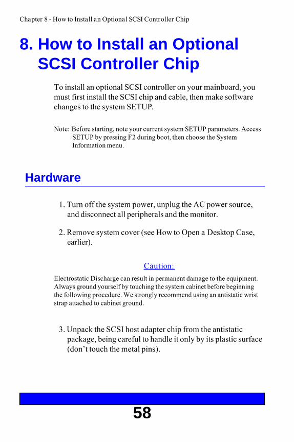
8. How to Install an OptionalSCSI Controller Chip
To install an optional SCSI controller on your mainboard, youmust first install the SCSI chip and cable, then make softwarechanges to the system SETUP.
Note: Before starting, note your current system SETUP parameters. AccessSETUP by pressing F2 during boot, then choose the SystemInformation menu.
Hardware
1. Turn off the system power, unplug the AC power source,and disconnect all peripherals and the monitor.
2. Remove system cover (see How to Open a Desktop Case,earlier).
Caution:Electrostatic Discharge can result in permanent damage to the equipment.Always ground yourself by touching the system cabinet before beginningthe following procedure. We strongly recommend using an antistatic wriststrap attached to cabinet ground.
3. Unpack the SCSI host adapter chip from the antistaticpackage, being careful to handle it only by its plastic surface(don’t touch the metal pins).
Chapter 8 - How to Install an Optional SCSI Controller Chip

59
Chapter 8 - How to Install an Optional SCSI Controller Chip
SCSI CableConnectorJ8
Pin 1
Pin 1
SCSI ChipSocketU17
4. Locate the SCSI host adapter socket on the mainboard andidentify the pin 1 (beveled) corner of the socket. If youneed help finding the SCSI host adapter socket, see thefigure above.
Caution:Make absolutely sure the SCSI host adapter chip is properly aligned in thesocket. There is only one correct way the chip will fit into this socket. Thisensures that the adapter is oriented properly.

60
5. Match the beveled Pin 1 corner of the SCSI host adapterwith the beveled Pin 1 corner of the socket. Carefully alignthe SCSI chip in the SCSI host adapter socket.
6. Using two fingers, gently press the chip into the socket. Becareful not to bend the pins.
7. Connect SCSI ribbon cable from SCSI port mainboardconnector (J8) to SCSI device. Make sure the red stripe istoward pin 1.
8. Replace cover, reconnect all peripherals and monitor.
9. Turn on power as you normally would.
Chapter 8 - How to Install an Optional SCSI Controller Chip
Pin 1 on SCSIAdapter Chip
Pin 1 on SCSIAdapter Socket

61
Software
1. Access the system SETUP utility by pressing F2 duringsystem boot.
2. Verify the following SCSI parameters in system SETUP,Main Menu, SCSI BIOS Enable sub-menu:
♦SCSI BIOS [Enabled]
♦SCSI Controller Address [340H]
♦Synchronous [Enabled]
♦Enhanced [Enabled]
♦Parity [Enabled]
♦Disconnect [Disabled]
3. The on-board SCSI controller always uses IRQ11, non-DMA. If other attached devices are using IRQ11, changetheir settings to a different IRQ setting. The SCSI I/O portdefault address is 340h (primary). The alternate address is140h, but is not currently supported by the system BIOS.
4. Verify your system configuration to ensure other systemparameters have not changed. If any parameters havechanged, re-enter them and reboot your system.
For SCSI software driver installation and operation information,refer to the appropriate Adaptec SCSI Device DriverInstallation Guide.
Chapter 8 - How to Install an Optional SCSI Controller Chip

62
Chapter 9 - Special Notes on the Pantera 90
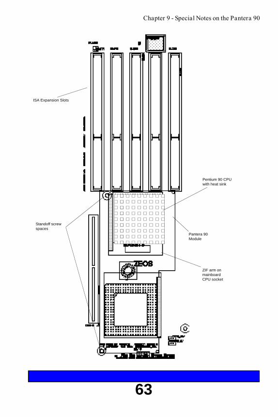
9. Special Notes on thePantera 90
The Pantera 90 computer uses a special daughter board calledthe Pantera 90 module. The Pantera 90 module plugs into theZIF (Zero Insertion Force) socket on the mainboard. In essence,the daughterboard replaces the mainboard CPU. The IntelPentium™ 90 CPU plugs into the ZIF socket on the Pantera 90module daughterboard and takes over as CPU for the system.
The Pantera 90 module uses two standoff screws to keep itraised over the mainboard.
63
Chapter 9 - Special Notes on the Pantera 90
ISA Expansion Slots
Standoff screwspaces
Pantera 90Module
ZIF arm onmainboardCPU socket
Pentium 90 CPUwith heat sink

64

65
CPU Intel Pentium (TM) Processor
Clock rate 60 MHz, 66 MHz, or 90MHz
ISA bus speed 7.5 MHz (60 MHz clock),8.25 MHz (66 MHz clock)
PCI local bus speed up to 132 MB/s(66MHz),up to 120 MB/s(60MHz)
Data path 8, 16, 32,64-bits
Expansion slots (8) Five 16-bit ISAThree 32-bit PCI local bus
Secondary Cache Mapping Direct
Secondary Cache Write policy Write-back
Secondary Cache Capacity 0KB, 256KB, or 512KB
Cache SIMM Type 256KB or 512KB Cache SIMM
Cache Speed 7ns/9ns
Memory Type 1, 2, 4, 8, 16, 32MB SIMMs
Memory Configuration 2, 4, 6, 8, 10, 12, 16, 24, 32, 64, 128,192 MBs
Operating Temperature 0°C to 35°C
Storage Temperature -20C to 60C
Operating Humidity 20%RH to 80%RH
Storage Humidity 10% RH to 90% RH
Mainboard Environmental Specifications
Mainboard Specifications
Mainboard Specifications
66
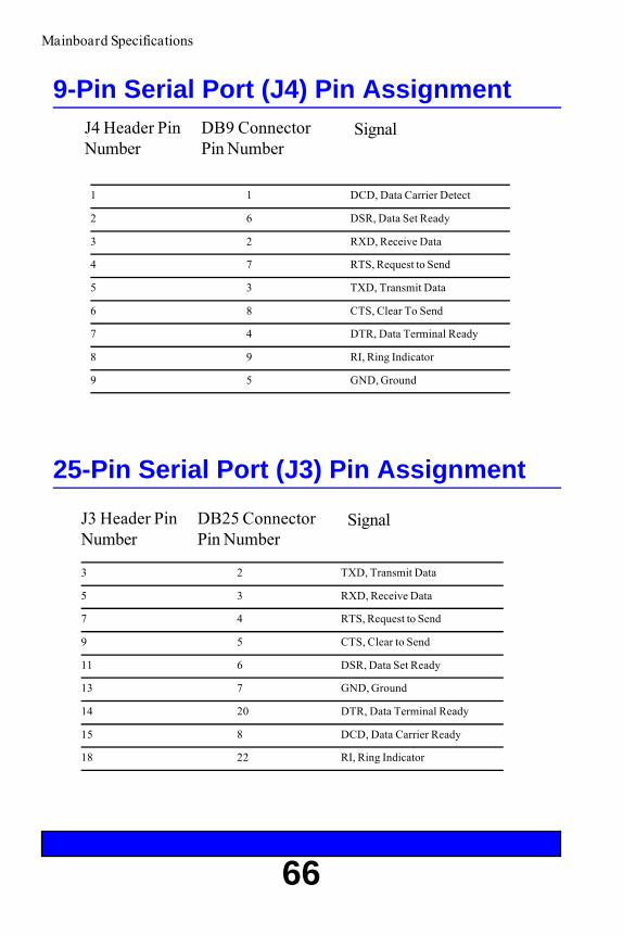
3 2 TXD, Transmit Data
5 3 RXD, Receive Data
7 4 RTS, Request to Send
9 5 CTS, Clear to Send
11 6 DSR, Data Set Ready
13 7 GND, Ground
14 20 DTR, Data Terminal Ready
15 8 DCD, Data Carrier Ready
18 22 RI, Ring Indicator
J3 Header PinNumber
DB25 ConnectorPin Number
9-Pin Serial Port (J4) Pin AssignmentJ4 Header PinNumber
DB9 ConnectorPin Number
Signal
25-Pin Serial Port (J3) Pin Assignment
Signal
1 1 DCD, Data Carrier Detect
2 6 DSR, Data Set Ready
3 2 RXD, Receive Data
4 7 RTS, Request to Send
5 3 TXD, Transmit Data
6 8 CTS, Clear To Send
7 4 DTR, Data Terminal Ready
8 9 RI, Ring Indicator
9 5 GND, Ground
Mainboard Specifications

67
9-Pin Serial Port (J4) Pin Assignment
25-Pin Serial Port (J3) Pin Assignment
22 - RI, Ring Indicator
20 - DTR, Data Terminal Ready
Mainboard Specifications
1 - DCD, Data Carrier Detect
2 - RXD, Receive Data
4 - DTR, Data Terminal Ready
3 - TXD, Transmit Data
5 - GND, Ground
6 - DSR, Data Set Ready
7 - RTS, Request to Send
8 - CTS, Clear To Send
9 - RI, Ring Indicator
8 - DCD, Data Carrier Ready
6 - DSR, Data Set Ready
5 - CTS, Clear to Send
4 - RTS, Request to Send
3 - RXD, Receive Data
2 - TXD, Transmit Data
7 - GND, Ground

68
Parallel Port (J2) Pin Assignment
1 1 STB, Strobe
3 2 PD0, Data Bit 0
5 3 PD1, Data Bit 1
7 4 PD2, Data Bit 2
9 5 PD3, Data Bit 3
11 6 PD4, Data Bit 4
13 7 PD5, Data Bit 5
15 8 PD6, Data Bit 6
17 9 PD7, Data Bit 7
19 10 ACK, Acknowledge
21 11 Busy, Busy
23 12 PE, Paper Empty
25 13 SLCT, Select
2 14 AFD, Auto Feed
4 15 ERR, Error
6 16 INIT, Initialize
8 17 SLIN, Select Input
10 18 GND, Ground
12 19 GND, Ground
14 20 GND, Ground
16 21 GND, Ground
18 22 GND, Ground
20 23 GND, Ground
22 24 GND, Ground
24 25 GND, Ground
J2 Header PinNumber
Parallel PortConnector PinNumber
Signal
Mainboard Specifications

69
Parallel Port (J2) Pin Assignment
Mainboard Specifications
14 - AFD, Auto Feed
15 - ERR, Error
16 - INIT, Initialize
17 - SLIN, Select Input
18 - GND, Ground
19 - GND, Ground
20 - GND, Ground
21 - GND, Ground
22 - GND, Ground
23 - GND, Ground
24 - GND, Ground
25 - GND, Ground
1 - STB, Strobe
2 - PD0, Data Bit 0
3 - PD1, Data Bit 1
4 - PD2, Data Bit 2
5 - PD3, Data Bit 3
6 - PD4, Data Bit 4
7 - D5, Data Bit 5
8 - PD6, Data Bit 6
9 - PD7, Data Bit 7
10 - ACK, Acknowledge
11 - Busy, Busy
12 - PE, Paper Empty
13 - SLCT, Select

70
Mainboard Specifications
SCSI Port Pin Assignment
J8 Header PinNumber
SCSI PortConnector PinNumber
Signal
2 2 SCD0, Data Bit 0
4 4 SCD1, Data Bit 1
6 6 SCD2, Data Bit 2
8 8 SCD3, Data Bit 3
10 10 SCD4, Data Bit 4
12 12 SCD5, Data Bit 5
14 14 SCD6, Data Bit 6
16 16 SCD7, Data Bit 7
18 18 SCDP, Parity
25 25 –, Open (not used)
26 26 TER_PWR, TerminationPower
1,3,5,7,9,11,13, (Same pin number GND, Ground15,17,19-24,27-31, as mainboard header)33-35,37,39,41,43,45,47,49
32 32 ATN, Attention
36 36 BSY, Busy
38 38 ACK, Acknowledge
40 40 RST, Reset
42 42 MSG, Message
44 44 SEL, Select
46 46 CD, Control/Data
48 48 REQ, Request
50 50 IO, Input/Output

71
Handy Cheat SheetHere are some of the most often needed or forgotten notes.
CTRL-ALT-DEL ...........................................................Warm RebootReset button, orPower button ................................................................... Cold RebootF2 during power up ..................................................... Access SETUPCTRL-BREAK, orCTRL-C ............................ Pause or Break an application or batch file
DOS Commands
COPY [filename] [drive:][path][newfilename] .................... copies a fileFORMAT [drive:] ..........................................erases and formats a diskDIR [drive:][path] ............. lists the files in a certain drive and directoryDEL [filename] ................................................................. deletes a fileMD[newdirectory] ............................................ makes a new directoryRD[directoryname] ............ removes and erases an empty, old directoryRENAME [oldfilename][newfilename] ............................ renames a fileCHKDSK [drive:] ............................. displays a status report for a diskCD[path] .............................................. changes to a different directoryCLS ............................................................................clears the screen
Common DOS file extensions
.BAK ..................................................................................backup file
.BAT ..................................................................................... batch file
.COM............................................................... command program file
.EXE............................................................... executable program file
.SYS ................................................................................... system file
.INI .............................................................Windows initialization file
.PIF................................................ Windows program information file
README files ................................ text files with special instructions

72
Handy Cheat SheetWindows Shortcuts
Ctrl-C ....................................................................... copy to clipboardCtrl-V ................................................paste or copy from the clipboardCtrl-X ...................................................... delete and copy to clipboardAlt-Tab ............................................ toggle between open applicationsAlt-Esc .................................................. jump to next open application
Wildcards - wildcards are special characters that can represent any othervalid numbers, letters, or symbols in a file name.
The asterisk represents any number of other characters.For example:
*.BAK would represent any file with the extension BAK.
GONOW.* would represent all files named GONOWwith any extension.
The question mark represents one single character.For example:
GONOW.?XE would represent any file named GONOWwith an extension ending in XE.
?ONOW.EX? would represent any five characterfilename ending in ONOW with EX as the first twocharacters of its extension.
?
*

73
DIP Switches - Small switches on a piece ofhardware such as a CPU, a printer, or an optioncard. DIP switch settings control various functionsand provide a system with information about itself.DIP stands for Dual In-Line Package.Directory - A list of the files stored on a disk or apart of a disk.Disk Drive - The physical device which allows thecomputer to read from and write to a disk. A floppydisk drive has a disk slot into which you insertfloppy disks. A hard disk drive is permanentlyfixed inside the system unit.DOS - Disk Operating System. A computerprogram which continuously runs and mediatesbetween the computer user and the ApplicationProgram, and allows access to disk data by diskfilenames. The Disk Operating System controls thecomputer’s input and output functions. SeeOperating System.File - A group of related pieces of informationcalled records, or entries, stored together on disk.Text files consist of words and sentences. Programfiles consist of codes and are used by computers tointerpret and carry out instructions.Floppy disk - a flat piece of flexible plastic coatedwith magnetic material and used to store datapermanently.Format - To prepare a new disk (or erase an oldone) so it can receive information. Formatting adisk divides it into tracks and sectors which createaddressable locations on it.Hard Disk Drive - Commonly called rigid diskdrives, or fixed disk drives. Unlike floppy disks,hard disks are fixed in place inside the system unit.They can process data faster and store many morefiles than floppy disks.Hardware - Any physical component of acomputer system, such as a monitor, printer,keyboard, or CPU.
Address (Physical) - A specific location in memorywhere a unit record, or sector, of data is stored.Application Program - Computer program thatactually performs a useful task. Word processors,spreadsheets, and desktop publishing programs areapplication programs.AUTOEXEC.BAT File - An MS-DOS batch filecontaining commands which execute automaticallywhen you turn on your computer.Batch File - A file containing several commandsthat execute in sequence as a group, or batch. MS-DOS batch files must have a filename extension of.BAT.Boot - Short for Bootstrap. Transfer of a diskoperating system program from storage on floppydisk or hard disk drive to computer’s workingmemory.Boot Disk - A disk with an operating systeminstalled which loads the system on power up.Character - Anything that can print in a singlespace on the page or the screen. Includes numbers,letters, punctuation marks, and graphic symbols.Command Processor - The part of an operatingsystem that processes commands entered by you.The command processor in MS-DOS is contained inthe COMMAND.COM file.CPU - Central Processing Unit. The piece ofhardware which interprets instructions, performs thetasks you indicate, keeps track of stored data, andcontrols all input and output operations.Crash - A malfunction in the computer hardware orsoftware, usually causing loss of data.Cursor - The highlighted marker which shows yourposition on the screen and moves as you enter wordsor numbers.Diagnostics - The tests and procedures thecomputer performs to check its internal circuitry andset up its configuration.
GlossaryThis glossary provides general definitions of key terms. For an expanded list look instandard reference books on computers.

74
GlossaryIDE - Integral Device Equipment. Also, IDE is anacronym for Integrated, Intelligent or ImbeddedDrive Electronics. An IDE drive has the controllerelectronics built into the drive itself and isconnected directly to the mainboard or to anadapter card.Jumper - A small electrical connector that alterssome of the computer’s functions. Short (makes aconnection) or Non-Short (no connection).Kilobyte (KB) - A unit used to measure storagespace (in a computer’s memory or on a disk). Onekilobyte equals 1024 bytes.LED - Light Emitting Diode. A substance thatilluminates when electricity passes through it, likethe indicator lights on the front panel of thecomputer.Local Bus - A set of addresses, data, and controlsignals that interface directly with the host CPU.Mainboard - A printed circuit board into whichother circuit boards can be plugged. Usually, itcontains the CPU, connectors for memory(SIMMs), secondary cache, SCSI host adaptersocket and expansion slots for add-on boards. Alsoknown as a motherboard.Memory - The area where your computer storesdata. Memory contents can be permanent andunalterable (ROM) or temporary (RAM).MHz - This stands for Megahertz, or cycles persecond.Operating System - A collection of programs thatallow a computer to control its operations. TheOperating System determines how programs run onthe computer and supervises all input and output -for example, MS-DOS.Parallel - The type of interface which transmitsdata in groups of bits. Printers usually use Parallelports.Peripheral - A device (such as, a printer or amodem) connected to a computer that depends onthe computer for its operation.Port - A physical input/output socket on acomputer where you can connect a peripheral.
RAM - Random Access Memory. The part of memorythat a computer can both read and write to. Theprograms you use are temporarily stored in RAM. Alldata stored in RAM is erased when you turn off thepower.Read - To copy data from one area to another. Forexample, when you open a text file stored on disk, thecomputer reads the data from the disk and displays it onthe screen.Reset - To reload a computer’s operating system so youcan retry a task or begin using a different operatingsystem. Resetting clears RAM.ROM - Read Only Memory. A portion of memory thatcan only be read and cannot be used for temporarystorage. ROM retains its contents even when you turnoff the power.Self Test - The initial diagnostics procedures a systemperforms to check its hardware.Setup - This refers (usually) to the program that is usedto load the CMOS data base with input from the user.SETUP sets the date, time, and configuration of diskdrives installed on the system.Software - The programs that enable your computer toperform the tasks and functions you indicate.Application programs are software.Subdirectory - A directory that originates from anotherdirectory (the root directory or some other directory).Subdirectories branch out from other directories.System Disk - A disk that contains the operatingsystem. A Boot Disk.Write - To store data on a disk.Write-Protect - To prevent a floppy disk from beingoverwritten by placing a write-protect tab over the notchon the side of the floppy disk (5.25") or setting thewrite-protect switch (3.5"). When a floppy disk is write-protected, you cannot erase, change, or record over itscontents.ZEOS - Greek God of computers.

75
IndexA
Advanced SETUP Menu 42Audio Port
features 25in SETUP 43
B
BIOS 31Boot Sequence 41
C
Cache memory, how to install 56Cache Video BIOS area 38CD-ROM Drive 51CLR1 jumper 28Com Port A: in SETUP 42Com Port B: in SETUP 42Controller Address 36Customer Assurance Program 3
D
Daylight Savings 33Desktop System
diagram 12how to open 16internal diagram 20
Disconnect 37Disk Drives 48Diskette Access 45Diskette Drive A: in SETUP 33Diskette Drive B: in SETUP 33DRAM speed 38Dual Write Enable Mode 38
E
Enhanced Parallel Port 37Expansion Board, how to install 46Extended Memory, in SETUP 34External Cache 38
F
Fixed Disk 0 Type 35. See also Hard DiskFixed disk boot sector 45Fixed Disk Menu in SETUP 34FLASH1 jumper 28Floppy Check 41Floppy Drive 49Floppy Swap 41
H
Hard Drive 50
I
Idt 7MP6157 256K Module: 38Integrated Peripherals 42
K
Key Click 40Keyboard Auto-repeat Delay 40Keyboard Auto-repeat Rate 40
L
Large Disk DOS Compatibility 42LBA Mode Control 35Logical Block Addressing 42

76
IndexM
MainboardConnectors 26Diagram 27Environmental specs 65Features 22Jumpers 28Specifications 65
Memory Control 38Memory, how to add 53Memory Shadow 39Mode, in SETUP 43Multi-Sector Transfer 35
N
Numlock 40
P
Pantera 90 62Parallel Port
features 25in SETUP 43
Parity 37Password on Boot 45PCI Devices in SETUP 43PCI Local Bus 23Physical Drive 35Pinouts, Serial and Parallel 66POST errors 41
R
RAM, how to add 52RFI Suppression 6
S
SCSI BIOS Enabled 36SCSI Controller, how to add 58SCSI Port, features 25Secondary Cache Subsystem 23Security 44Serial Port, features 24Set Supervisor Password 44Set User Password 44SETUP 31SETUP prompt 41Shadow Memory Regions 39SIMMs, how to install 54Summary screen 40Synchronous 36System Backup Reminder 45System Date 33System Memory
how to add 52in SETUP 34
System Shadow 39System Time 33
T
Turbo mode 23
V
Vertical Systemdiagram 14how to open 18internal diagram 21
Video Shadow 39Video System in SETUP 33Virus Check Reminder 45

Late Changes
The following changes arrived too late for printing:
There are no corrections at this time.


![Acesso à Dados – ZEOS x Delphi [Modo de Compatibilidade] · referenciadas no Delphi Pacotes de instalação do ZEOS. Instalação Copie a pasta ZEOS para um local no seu disco](https://static.fdocuments.net/doc/165x107/5c265e1109d3f22a598c6460/acesso-a-dados-zeos-x-delphi-modo-de-compatibilidade-referenciadas-no.jpg)