The Comparison of the fire suppression performance of ... · The Comparison of the Fire Suppression...
20
The Comparison of the Fire Suppression Performance of Compressed-Air Foam with Foam Water Sprinklers on Free- Flowing Heptane Spill Fires Crampton, G.; Kim, A. IRC-RR-174 September 2004 http://irc.nrc-cnrc.gc.ca/ircpubs
Transcript of The Comparison of the fire suppression performance of ... · The Comparison of the Fire Suppression...
The Comparison of the Fire Suppression Performance of
Compressed-Air Foam with Foam Water Sprinklers on Free-Flowing Heptane Spill Fires
Crampton, G.; Kim, A.
IRC-RR-174
September 2004
http://irc.nrc-cnrc.gc.ca/ircpubs
The Comparison of the Fire Suppression Performance of Compressed-Air Foam with Foam Water Sprinklers on Free-Flowing Heptane Spill Fires
Research Report RR-174
Date of Issue: September 2004
Authors: George Crampton and Andrew Kim
Published by Institute for Research in Construction National Research Council Canada Ottawa, Canada K1A 0R6
Abstract
Compressed-air foam (CAF) has been proven to be an effective fire suppression
material for both class A and B fires. Comparison testing between CAF and standard
foam water sprinklers had been conducted previously to quantify the amount of foam
required to extinguish a liquid fuel fire that was contained within the bounds of a pan as
specified in the UL162 Foam Equipment and Liquid Concentrates standard. To date
only a few smaller scale tests had been conducted using CAF to extinguish free flowing
spill fires.
This paper describes a series of full-scale Class B fire tests designed to compare CAF
(Compressed-air Foam) and standard foam water sprinklers in extinguishing free flowing
spill fires with and without shielded areas.
i
Table of Contents
Abstract………………………………………………………………………………….……i
Table of Contents……………………………………………………………………….…..ii
1.0 Introduction…………………………………………………………………….……1
1.1 Background………………………………………………………….……..1
1.2 Project Description…………………………………………………….…..1
2.0 Test Details…………………………………………………………………………2
2.1 Test Facility………………………………………………………………...2
2.2 Foam Delivery Systems…………………………………………………..3
2.3 Instrumentation…………………………………………………………….4
2.4 Test Procedure…………………………………………………………….5
3.0 Results………………………………………………………………………………5
3.1 Pan and Spill fire Comparison Tests……………………………………5
3.2 Unshielded Spill Fire Tests………………………………………………9
3.3 Shielded Spill Fire Tests………………………………………………..11
3.4 Milspec Shielded Fire Tests……….…………………………………...13
4.0 Conclusions……………………………………………………………………….15
5.0 Acknowledgements………………………………………………………………16
6.0 Bibliography………………………………………………………………………16
ii
1.0 Introduction
1.1 Background
Pan fires are an excellent, reproducible way to evaluate and compare extinguishing
systems. Pans are used in many standard test methods and CAF has proven to have
superior performance when compared to conventional foam water sprinkler systems in
these tests. Concerns in the industry have arisen about CAF’s ability to extinguish a
more realistic fire scenario involving free-flowing spill fires. These fires are especially
difficult to extinguish when they are shielded from the direct delivery of foam from the
nozzle. This would be the case in hangers where large floor areas would be shielded by
aircraft or other service vehicles.
In order to address these concerns a series of spill fire tests were designed to evaluate
the performance of CAF on increasing spill fire sizes with and without shielding. Two
foam water sprinkler tests would also be conducted for the purpose of comparison.
1.2 Project Description
This report describes a series of 9 full-scale Class B fire tests designed to compare CAF
and foam water sprinklers in extinguishing free-flowing heptane pool fires, increasing in
size from 4.65 m2 to 14 m2 on a 6m by 6m flat concrete slab. The flow of fuel would be
controlled by a valve removed from the fire location and the fuel would be delivered to
the slab through a 25.4 mm diameter steel pipe. In addition to visual observations,
radiant heat flux was also measured at a point 1.83 m from the edge of the fuel
boundary and 1.5 m off the ground. This would allow a comparison to be made with the
previous pan fire tests of the same size. The fuel drum was positioned on weigh scales
to monitor the flow of fuel during the tests.
The first 2 tests would confine the spill to a 4.65 m2 area using a bead of silicon caulking.
Due to the uneven characteristics of the slab this was necessary to achieve the
comparison data. Tests 3 to 9 would have no confinement and the fuel would be
allowed to flow freely over the slab. Tests 6 to 9 would have a 1 m by 1 m table
positioned over a fuelling outlet preventing the foam from landing directly on the fuel
surface under the table. To extinguish this scenario, the foam must be fluid enough to
1
flow under the table. Tests 8 and 9 would use the standard foam sprinklers in place of
the CAF system.
2.0 Test Details
2.1 Test Facility
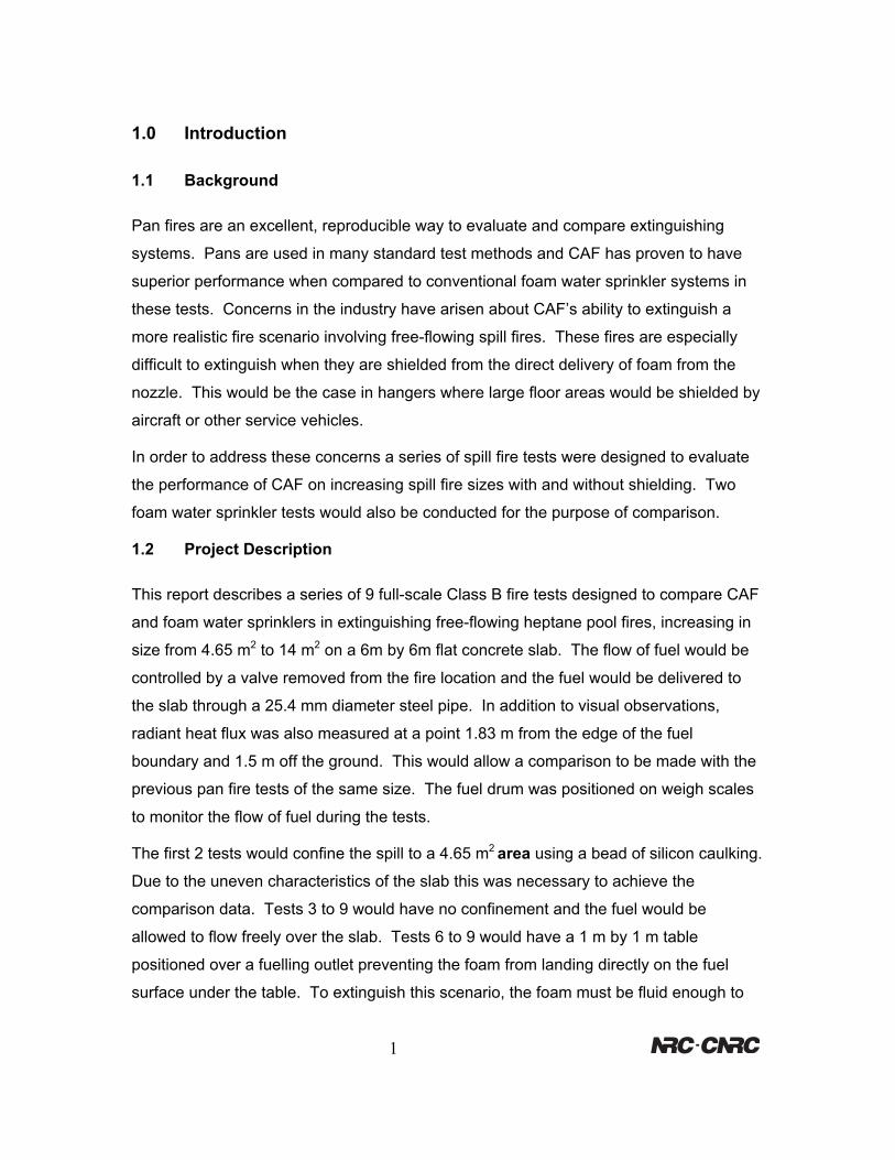
The tests were conducted indoors at the Fire Research Program’s Fire Laboratory where
the burn hall measures 55 m long by 30 m wide by 12 m high. At the time of the
experiments the ambient temperature was between 20 and 25 degrees Celsius. The
36 m2 test area was formed level using fibre reinforced concrete (see figure 1).
Concentric circles were painted on the slab at 2.44 m, 3.44 m, 4.21, and 4.87 m in
diameter. Each circle represents an increase in area and fire size by factors of 1, 2, 3,
and 4 respectively.
A grid of 4 CAF nozzles or sprinkler heads were positioned 10.7 m above the slab at a
3.73 m by 3.73 m spacing. Extinguishment data was taken using a 2 w/cm2 heat flux
meter and Solartron data acquisition system. The heptane fuel was delivered through a
preset valve from a 205 litre drum mounted on weigh scales shown in the area on the left
in figure 1.
Figure 1. Fire test facility
2
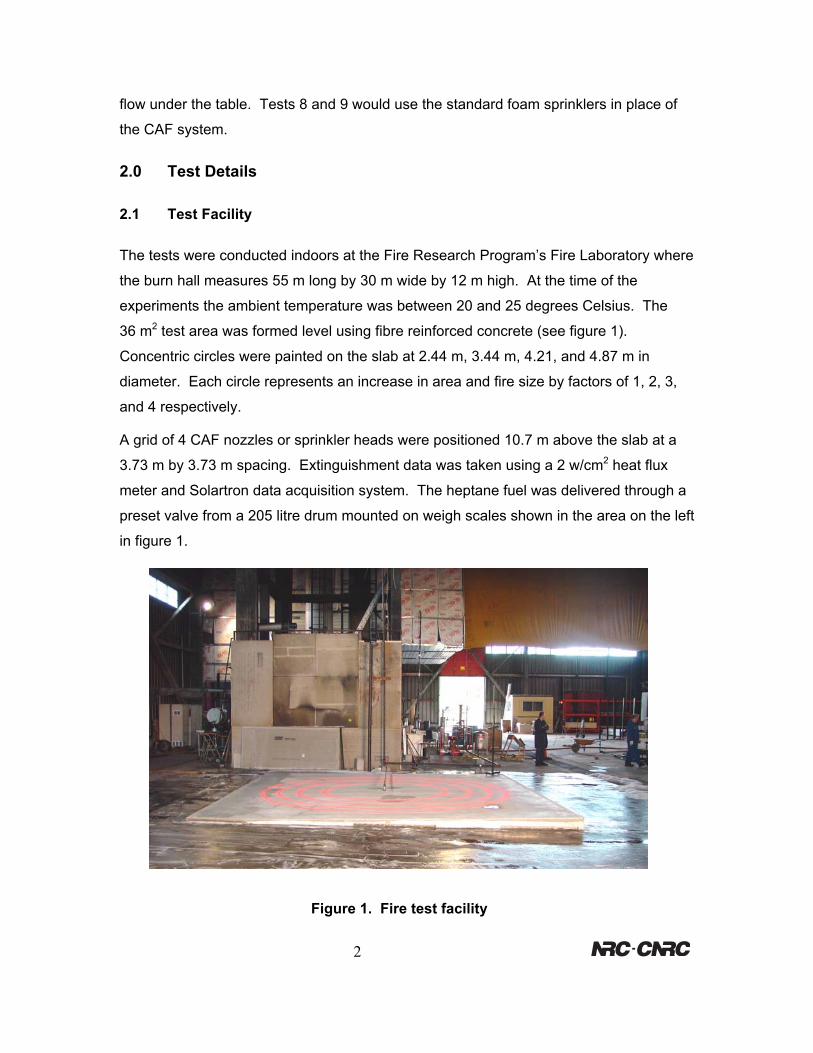
2.2 Foam Delivery Systems
The foam delivery system was supplied by FireFlex Systems Inc. and is shown in figure 2.
This system mixes the correct amount of water, air and foam concentrate so that CAF can
be formed in the delivery piping.
Figure 2. Foam delivery apparatus.
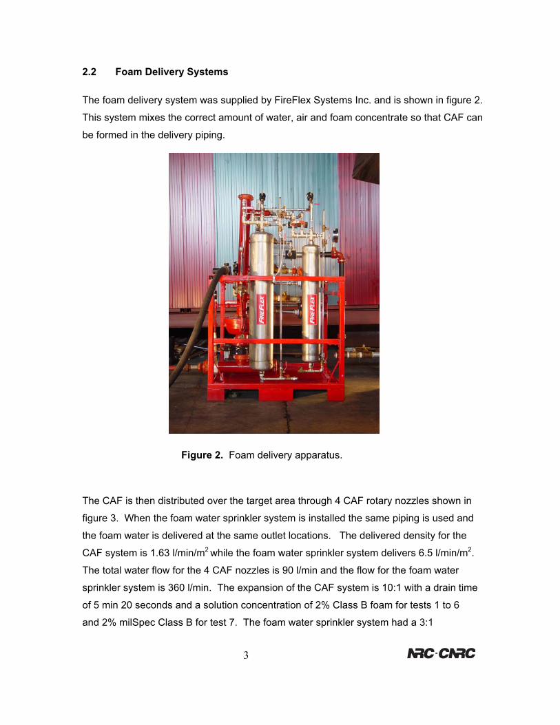
The CAF is then distributed over the target area through 4 CAF rotary nozzles shown in
figure 3. When the foam water sprinkler system is installed the same piping is used and
the foam water is delivered at the same outlet locations. The delivered density for the
CAF system is 1.63 l/min/m2 while the foam water sprinkler system delivers 6.5 l/min/m2.
The total water flow for the 4 CAF nozzles is 90 l/min and the flow for the foam water
sprinkler system is 360 l/min. The expansion of the CAF system is 10:1 with a drain time
of 5 min 20 seconds and a solution concentration of 2% Class B foam for tests 1 to 6
and 2% milSpec Class B for test 7. The foam water sprinkler system had a 3:1
3
expansion with a drain time < 1 min and a solution concentration of 3% Class B foam for
test 8 and 3% milSpec Class B for test 9.
Figure 3. CAF Delivery Nozzle
2.3 Instrumentation
The solution flow was monitored using a calibrated Krohne model Ecoflux 1010 Magnetic
flow-meter and the airflow was measured using a Brooks Model 1112A09G3B1A
rotometer. Pressures were measured using calibrated pressure gauges, and foam
expansions and drain times were determined by weight using a Mettler PC4400
calibrated balance. Radiant heat flux measurements were taken using a Medtherm Heat
flux transducer Model 64-02-14 Serial # 57496 and recorded on a Solartron model 3595
IMP data acquisition system. The tests were recorded on a the Sony Model DCR-
TRV340, 8 mm digital video tape and still photos were taken using a Sony Model DSC-
F707 digital camera.
.
4
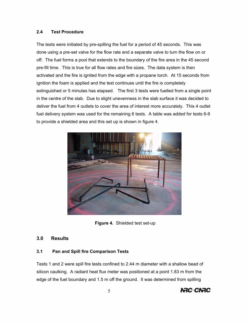
2.4 Test Procedure
The tests were initiated by pre-spilling the fuel for a period of 45 seconds. This was
done using a pre-set valve for the flow rate and a separate valve to turn the flow on or
off. The fuel forms a pool that extends to the boundary of the fire area in the 45 second
pre-fill time. This is true for all flow rates and fire sizes. The data system is then
activated and the fire is ignited from the edge with a propane torch. At 15 seconds from
ignition the foam is applied and the test continues until the fire is completely
extinguished or 5 minutes has elapsed. The first 3 tests were fuelled from a single point
in the centre of the slab. Due to slight unevenness in the slab surface it was decided to
deliver the fuel from 4 outlets to cover the area of interest more accurately. This 4 outlet
fuel delivery system was used for the remaining 6 tests. A table was added for tests 6-9
to provide a shielded area and this set up is shown in figure 4.
Figure 4. Shielded test set-up
3.0 Results
3.1 Pan and Spill fire Comparison Tests
Tests 1 and 2 were spill fire tests confined to 2.44 m diameter with a shallow bead of
silicon caulking. A radiant heat flux meter was positioned at a point 1.83 m from the
edge of the fuel boundary and 1.5 m off the ground. It was determined from spilling
5
heptane onto a water base that 8 l/min would be required to sustain a 2.44 m diameter
fire. Since the surface of the concrete was rougher than water it was decided to spill 11
l/min. Based on the heat of combustion for heptane this translates to a 6 megawatt fire.
It was observed during the test that the fire did extend beyond the caulking boundary
before the foam was applied. This indicated that the estimate for the flow rate of the spill
was correct at around 8 l/min. The pan fire of the same size consumes 21.3 l/min and
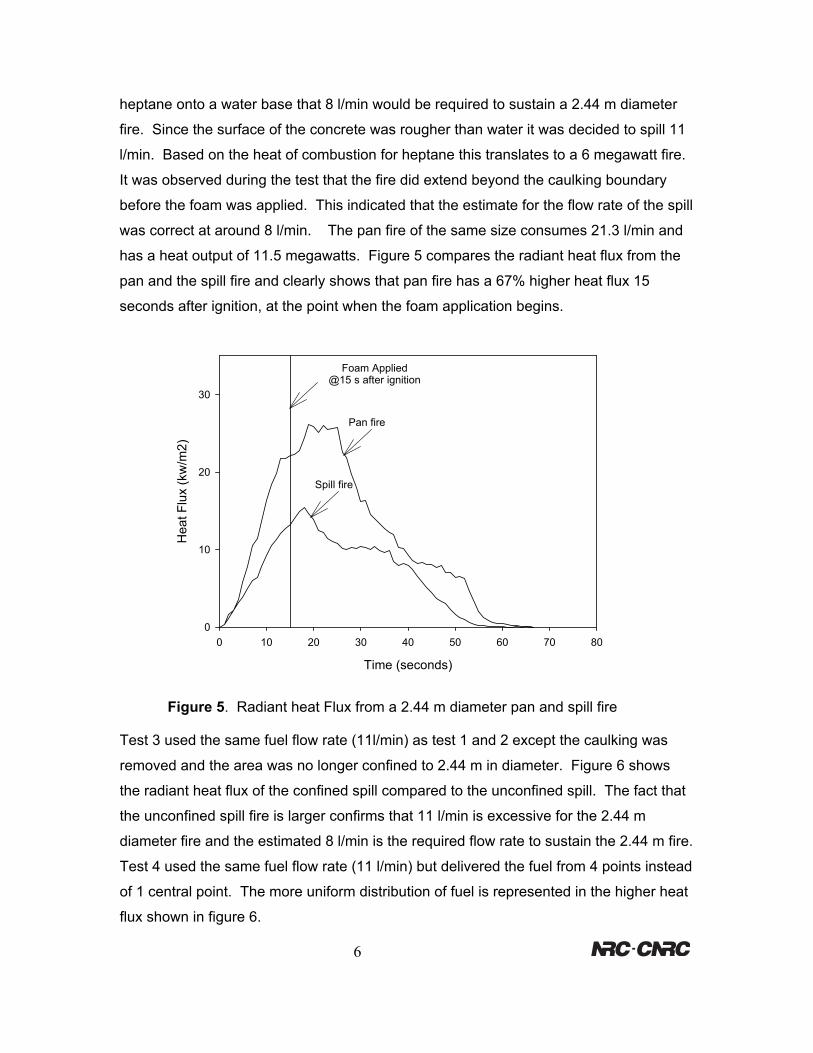
has a heat output of 11.5 megawatts. Figure 5 compares the radiant heat flux from the
pan and the spill fire and clearly shows that pan fire has a 67% higher heat flux 15
seconds after ignition, at the point when the foam application begins.
Time (seconds)
0 10 20 30 40 50 60 70 80
Hea
t Flu
x (k
w/m
2)
0
10
20
30
Foam Applied@15 s after ignition
Pan fire
Spill fire
Figure 5. Radiant heat Flux from a 2.44 m diameter pan and spill fire
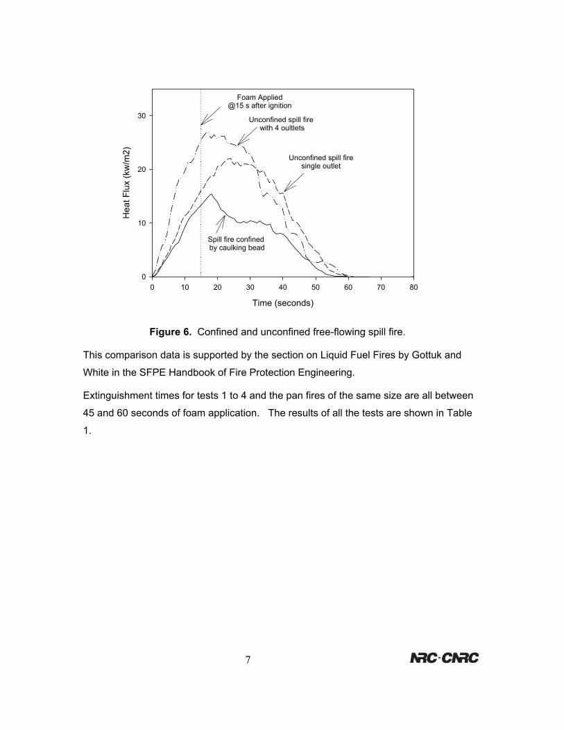
Test 3 used the same fuel flow rate (11l/min) as test 1 and 2 except the caulking was
removed and the area was no longer confined to 2.44 m in diameter. Figure 6 shows
the radiant heat flux of the confined spill compared to the unconfined spill. The fact that
the unconfined spill fire is larger confirms that 11 l/min is excessive for the 2.44 m
diameter fire and the estimated 8 l/min is the required flow rate to sustain the 2.44 m fire.
Test 4 used the same fuel flow rate (11 l/min) but delivered the fuel from 4 points instead
of 1 central point. The more uniform distribution of fuel is represented in the higher heat
flux shown in figure 6.
6
Time (seconds)
0 10 20 30 40 50 60 70 80
Hea
t Flu
x (k
w/m
2)
0
10
20
30
Foam Applied@15 s after ignition
Unconfined spill firesingle outlet
Spill fire confined by caulking bead
Unconfined spill fire with 4 oultlets
Figure 6. Confined and unconfined free-flowing spill fire.
This comparison data is supported by the section on Liquid Fuel Fires by Gottuk and
White in the SFPE Handbook of Fire Protection Engineering.
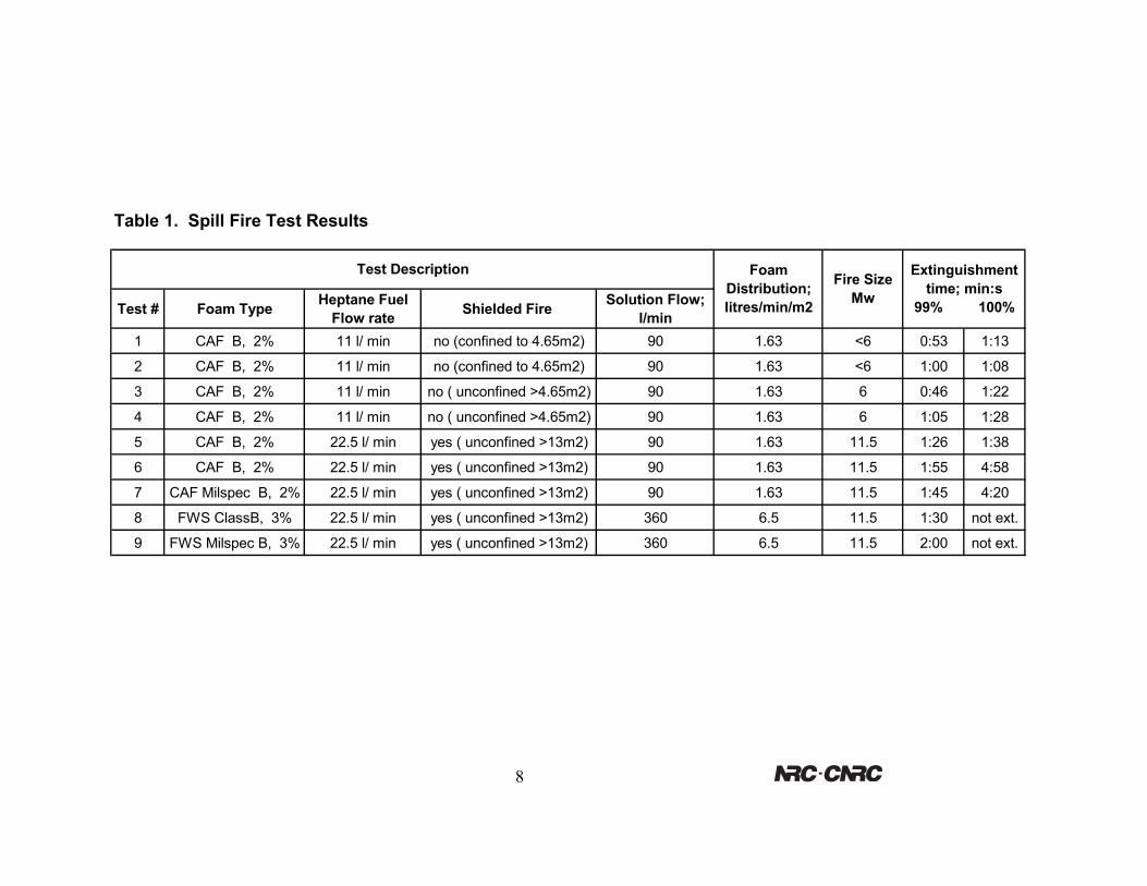
Extinguishment times for tests 1 to 4 and the pan fires of the same size are all between
45 and 60 seconds of foam application. The results of all the tests are shown in Table
1.
7
8
Table 1. Spill Fire Test Results
Test # Foam Type Heptane Fuel Flow rate Shielded Fire Solution Flow;
l/min1 CAF B, 2% 11 l/ min no (confined to 4.65m2) 90 1.63 <6 0:53 1:13
2 CAF B, 2% 11 l/ min no (confined to 4.65m2) 90 1.63 <6 1:00 1:08
3 CAF B, 2% 11 l/ min no ( unconfined >4.65m2) 90 1.63 6 0:46 1:22
4 CAF B, 2% 11 l/ min no ( unconfined >4.65m2) 90 1.63 6 1:05 1:28
5 CAF B, 2% 22.5 l/ min yes ( unconfined >13m2) 90 1.63 11.5 1:26 1:38
6 CAF B, 2% 22.5 l/ min yes ( unconfined >13m2) 90 1.63 11.5 1:55 4:58
7 CAF Milspec B, 2% 22.5 l/ min yes ( unconfined >13m2) 90 1.63 11.5 1:45 4:20
8 FWS ClassB, 3% 22.5 l/ min yes ( unconfined >13m2) 360 6.5 11.5 1:30 not ext.
9 FWS Milspec B, 3% 22.5 l/ min yes ( unconfined >13m2) 360 6.5 11.5 2:00 not ext.
Extinguishment time; min:s
99% 100%
Foam Distribution; litres/min/m2
Test DescriptionFire Size
Mw
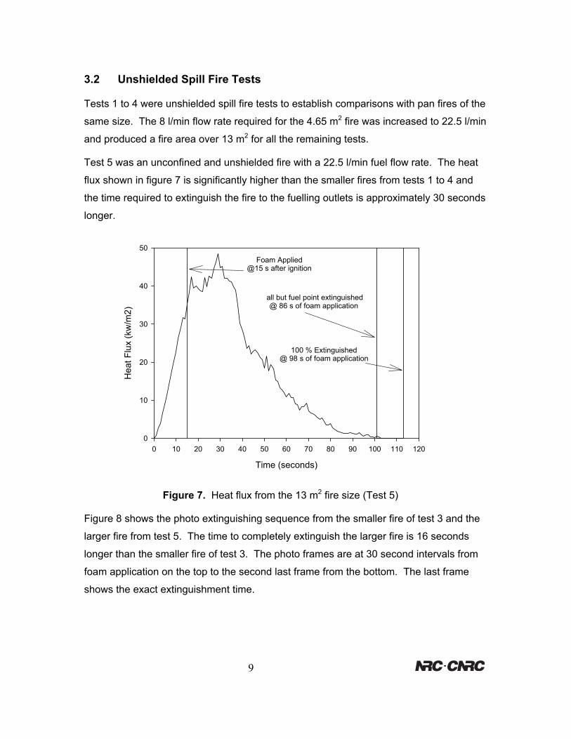
3.2 Unshielded Spill Fire Tests
Tests 1 to 4 were unshielded spill fire tests to establish comparisons with pan fires of the
same size. The 8 l/min flow rate required for the 4.65 m2 fire was increased to 22.5 l/min
and produced a fire area over 13 m2 for all the remaining tests.
Test 5 was an unconfined and unshielded fire with a 22.5 l/min fuel flow rate. The heat
flux shown in figure 7 is significantly higher than the smaller fires from tests 1 to 4 and
the time required to extinguish the fire to the fuelling outlets is approximately 30 seconds
longer.
Time (seconds)
0 10 20 30 40 50 60 70 80 90 100 110 120
Hea
t Flu
x (k
w/m
2)
0
10
20
30
40
50Foam Applied
@15 s after ignition
all but fuel point extinguished@ 86 s of foam application
100 % Extinguished@ 98 s of foam application
Figure 7. Heat flux from the 13 m2 fire size (Test 5)
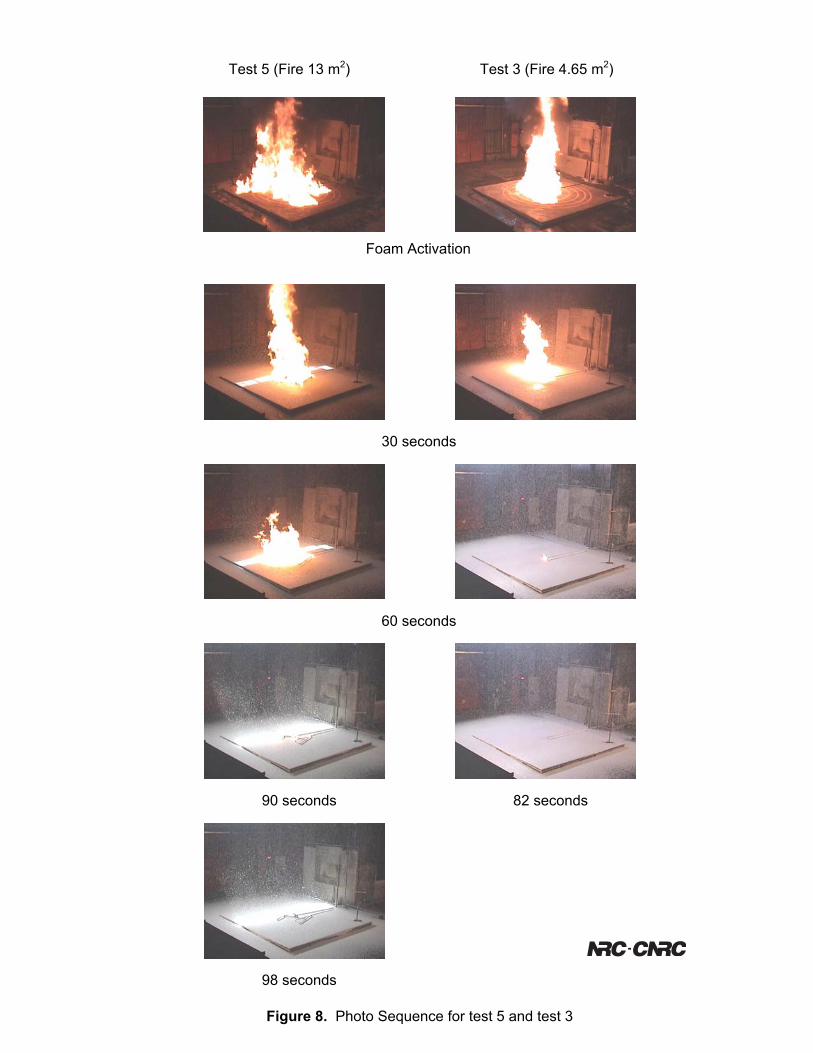
Figure 8 shows the photo extinguishing sequence from the smaller fire of test 3 and the
larger fire from test 5. The time to completely extinguish the larger fire is 16 seconds
longer than the smaller fire of test 3. The photo frames are at 30 second intervals from
foam application on the top to the second last frame from the bottom. The last frame
shows the exact extinguishment time.
9
Test 5 (Fire 13 m2) Test 3 (Fire 4.65 m2)
Foam Activation
10
Figure 8. Photo
30 seconds
60 seconds 90 secondsSequence for test 5
82 seconds
98 seconds
and test 3
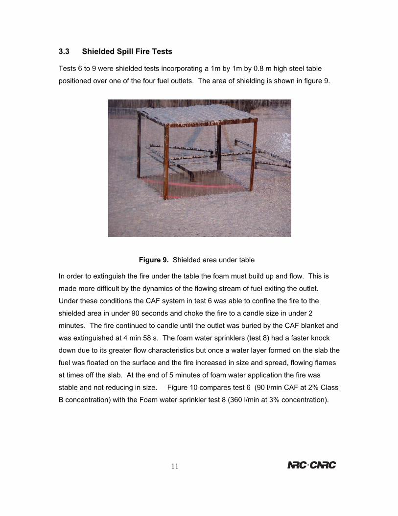
3.3 Shielded Spill Fire Tests
Tests 6 to 9 were shielded tests incorporating a 1m by 1m by 0.8 m high steel table
positioned over one of the four fuel outlets. The area of shielding is shown in figure 9.
Figure 9. Shielded area under table
In order to extinguish the fire under the table the foam must build up and flow. This is
made more difficult by the dynamics of the flowing stream of fuel exiting the outlet.
Under these conditions the CAF system in test 6 was able to confine the fire to the
shielded area in under 90 seconds and choke the fire to a candle size in under 2
minutes. The fire continued to candle until the outlet was buried by the CAF blanket and
was extinguished at 4 min 58 s. The foam water sprinklers (test 8) had a faster knock
down due to its greater flow characteristics but once a water layer formed on the slab the
fuel was floated on the surface and the fire increased in size and spread, flowing flames
at times off the slab. At the end of 5 minutes of foam water application the fire was
stable and not reducing in size. Figure 10 compares test 6 (90 l/min CAF at 2% Class
B concentration) with the Foam water sprinkler test 8 (360 l/min at 3% concentration).
11

A
Figure 10. Extin
Foam
ctivation
12
guishment sequences at 30 s intervals
Continued from
Adjacent column
Test 6 (CAF)
Test 8 (FW Sprinklers)
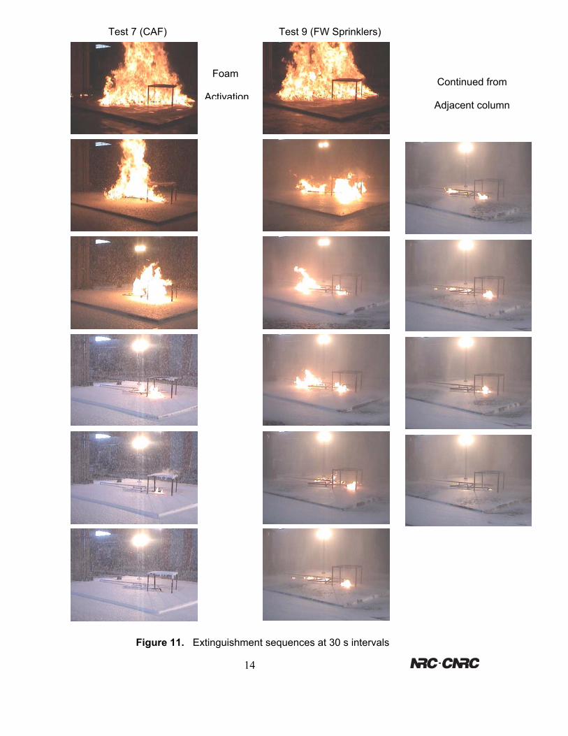
3.4 Milspec Shielded Fire Tests
Test 7 and test 9 had the same conditions as tests 6 and 8 except the regular Class B
foam was replaced with milspec Class B foam. The milspec foam performed better than
the standard foam in both the CAF and foam water sprinkler tests. The greatest
difference was the initial knock down time being 20 to 30 seconds faster with the milspec
foam. In the case of the foam water sprinklers it also controlled the fire better than the
standard foam keeping the flare-ups suppressed and not allowing fire to spread as easily
after several minutes of application. At the end of the 5 minute application time it was
unable to completely extinguish the fire in the foam water sprinkler test but the fire was
small and confined to the shielded area at the fuel outlet. The CAF test was able to
completely bury the outlet and extinguish the fire in 4 minutes and 20 seconds. Figure
11 shows the side-by-side photo extinguishment sequences for the milspec foam tests.
13
A
Foam
ctivation
14
Continued from
Adjacent column
Test 7 (CAF)
Test 9 (FW Sprinklers)Figure 11. Extinguishment sequences at 30 s intervals
4.0 Conclusions
The CAF system was able to suppress a 2.44 m diameter free-flowing spill fire as fast as
the 2.44 m diameter pan fire. It took longer to completely extinguish the spill fire due to
the difficulty in covering the fuel flowing from the outlet. When the fire was increased to
3 times the area and heat release, the CAF system took less than 30 seconds longer to
suppress the fire and only 16 seconds longer to completely extinguish it. The foam
water sprinkler system was able to suppress the spill fire faster than the pan fire due to
the addition of the fast flowing foam water on the slab combining with the foam water
landing on the fuel surface directly. The pan fire must be extinguished by the latter
method only. After only 30 seconds of discharge the depth of foam water on the slab
was enough to reduce the benefit of the flowing foam water and allow the fuel to ride on
top without a great deal of interaction between the two. In the standard Class B foam
tests this gave the fire the opportunity to actually grow in size and free flow off of the
slab. This situation is not desirable since the fire could be floated out of the protected
zone or be allowed to burn back quickly should the system run out of concentrate or
water. After the sprinkler test was over there was no fuel left on the slab to clean up. All
of the fuel was deposited into the trenched area which had filled and overflowed. In
contrast to this the CAF system was able to build up and completely extinguish the fire.
After 30 seconds the CAF had build up on the slab and began to flow. The flow of CAF
unlike the flow of foam water was able to cover the surface of the fuel and not flow under
it. At the end of the tests most of the fuel remained on the slab in the protected zone
and the less dense CAF had covered the fuel surface and overflowed the slab leaving
the fuel behind. This could be extremely beneficial in fuel storage areas protected by
dykes where the fuel can be contained within the dyke and the CAF can overflow without
the danger of spreading the fuel.
The CAF system was able to suppress the large free-flowing spill fires using 25% of the
water flow and a factor of 6 less concentrate when compared to the foam water sprinkler
system. It was able to extinguish the fires completely by covering the fuel outlet while
the foam water sprinkler system could not. CAF was able to flow under the shielded
area after 30 seconds of discharge. Visibility was well maintained throughout the CAF
tests with very low steam production.
15
5.0 Acknowledgements
The authors wish to thank Jean-Pierre Asselin and the staff of FireFlex Systems Inc.,
Michael Ryan and the staff of the Fire Research Program for their assistance and
contributions to this test series.
6.0 Bibliography
1. Crampton, G.P., et al. A new Fire Suppression Technology, NFPA Journal, Vol.
93, No. 4, National Fire Protection Association, Quincy, MA 1999.
2. Kim, A.K. and Dlugorski, B.Z., An Effective Fixed Foam System using
Compressed Air, Proceedings of the International Conference on Fire Research
and Engineering, Society of Fire Protection Engineers, Orlando, FL, 1995.
3. CAN/ULC-S560-98 Standard for Category 3 Aqueous Film-Forming Foam
(AFFF) Liquid Concentrates.
4. UL 162, Standard for Foam Equipment and Liquid Concentrates
5. NFPA 412 – Standard for Evaluating Aircraft Rescue and Fire Fighting Foam
Equipment, National Fire Protection Association, Quincy, MA 1998.
16