The CO2CRC Otway Project - sacccs.org.za in saline formations – Otway Basin ... SPM and Drilling...
59
Presenting to SACCCS Conference 24 Oct 2011 The CO2CRC Otway Project Dr Matthias Raab Program Manager Storage Cooperative Research Centre for Greenhouse Gas Technologies (CO2CRC) © CO2CRC All rights reserved
Transcript of The CO2CRC Otway Project - sacccs.org.za in saline formations – Otway Basin ... SPM and Drilling...

Presenting to
SACCCS Conference
24 Oct 2011
The CO2CRC Otway Project
Dr Matthias Raab Program Manager Storage
Cooperative Research Centre
for Greenhouse Gas
Technologies (CO2CRC) © CO2CRC
All rights reserved

Porosity vs Permeability
Tim Tam vs Aero Chocolate – can you spot the difference?


Key aspects for geological storage of CO2
• Where can we store? (Site Selection / Characterisation)
• How much can we store? (Storage Capacity)
• How can we best get it in there? (Injectivity)
• How do we know it will stay there? (Containment)
• How can we tell? (Measuring, monitoring, verification)
• How much will it cost? (Economics)
• What is the Risk? (Risk Assessment / Management)
• Making it happen (Regulatory, Liability, Public Perception)

CO2CRC Storage Program
• 1.0 Program Management
• 1.1 Otway Operations
• 1.2 Stage 1 Integration
• 1.3 Otway Saline Aquifer
• 1.4 Storage in Saline Aquifers
• 1.5 Reactive Reservoir Rocks
• 1.6 Geomechanics of Seals
• 1.7 Reservoir Modelling
• 1.8 Monitoring and Verification
• 3.2 Risk Assessment
• Stage 1: 65kt CO2 injected in depleted Gas Field
• Stage 2: Researching CO2 storage in saline aquifers
• Nine major research streams
• Two large field experiments (2b &2c)
• 79 researchers across 11 Institutions, 15 current PhD students
• 2011-12 FY budget of $11,900,000
• CO2 Sequestration facility in SW Victoria
Conducting world class research into Geological Carbon Storage

Program 1: Storage Research
1.0 Storage Science and Management
1.1 Development and operation of geological
storage research facilities, Otway site
1.2 Otway Phase I integration
1.3 CO2 storage in saline formations –
Otway Basin
1.4 Understanding CO2 storage in saline aquifers
1.5 Reactive reservoir rocks and their impact on
CO2 storage potential trapping
1.6 Seal geomechanics and potential for
CO2 leakage
1.7 Predictive modelling of storage reservoirs
1.8 Improved monitoring and verification
1.9 Developing CCS Risk Assessment Methodology

Structure of the Storage Program
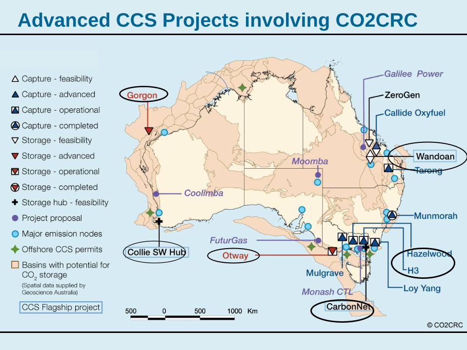
Advanced CCS Projects involving CO2CRC

Major challenges for CCS
• Decreasing the cost of capturing and separating CO2
from major stationary sources
• Identification of safe and secure geological sites for the
safe storage of CO2 from major sources
• Ensuring public confidence in CCS technology through
communication, community consultation, education and
the establishment of an effective regulatory regime
• Large scale deployment of CCS
• Uncertain policy setting

What have been challenges for CO2CRC in the past year?
• Transitioning to the new phase of CO2CRC, and new
members, imposed a significant administrative burden
• New staff appointments
• Costs pressures from the resources boom
• Engaging with industry during boom times
• Funding for expensive and complex operations
• Uncertainties with carbon policy
• Maintaining research cooperation in a competitive
environment
• External funding complexities and opportunities

What have been some of the successes of CO2CRC in the past year?
• Maintenance of position as a leading collaborative CCS
R&D organisation, based in Australia, working globally.
• Addresses and integrates capture and storage systems
• Brings industry sectors together (coal, gas, power, etc)
• Brings together Commonwealth, States, local government
and the community in the Otway Project
• Includes major research institutions - CSIRO, GA,
Universities, major overseas institutions (LBNL, KIGAM)
• Bring together approx. 200 CCS researchers
• Broad international perspective and experience
• Successful track record in running major CCS facilities
• Number of patents and other IP

The CO2CRC Otway Project
• Australia’s only Sequestration Facility
• One of few operational sequestration sites in the world
• Operating since 2008
• Research and injection into depleted hydrocarbon reservoir (Stage 1)
• Research and injection into saline aquifer (Stage 2)
• Unique research facility with global collaboration
• Concept, research and facilities provide blueprints to other CCS projects
• Will remain Australia’s only CO2 injection site at least until 2015.

Getting a Carbon Storage up and running
The CO2CRC Otway Project Stages 1 & 2
The simple concept
• Someone who likes the project to succeed
• Source of CO2
• Suitable storage sites nearby
• Permits and regulations
• Local community agreement
• $$$
• Research capacity
• demonstrating safe Geological Carbon Storage, and
• ways to measure, monitor and assure that it is safe
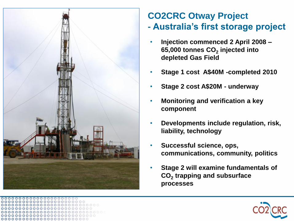
CO2CRC Otway Project
- Australia’s first storage project • Injection commenced 2 April 2008 –
65,000 tonnes CO2 injected into
depleted Gas Field
• Stage 1 cost A$40M -completed 2010
• Stage 2 cost A$20M - underway
• Monitoring and verification a key
component
• Developments include regulation, risk,
liability, technology
• Successful science, ops,
communications, community, politics
• Stage 2 will examine fundamentals of
CO2 trapping and subsurface
processes
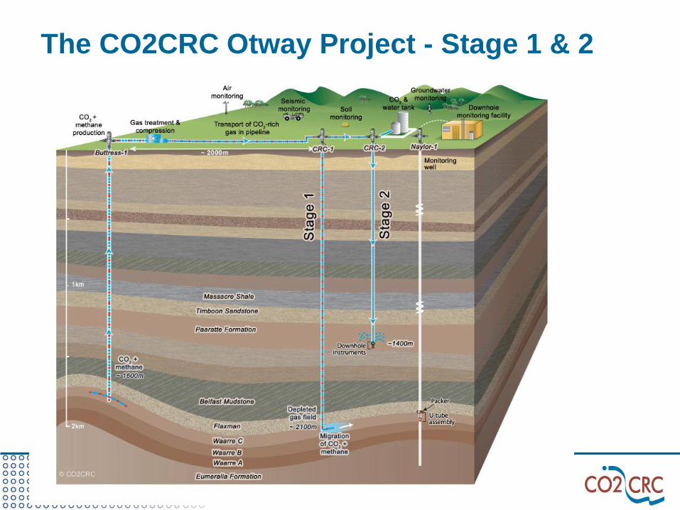
The CO2CRC Otway Project - Stage 1 & 2

CO2CRC Otway Project Aerial View
Buttress well – CO2 source
Naylor-1 well – ex reservoir storage
CRC-2 well – saline aquifer storage 1.4 km
Visitors centre
CRC-1 injection well
CO2 migration
CO2 pipeline

Risk Example – Pre Implementation

Regulatory Approvals
Activity Approvals/Permits Regulator Application Process
Production of CO2 Production Plan DPI - Petroleum Act 2000 (DPI).
Compression & Transport of
CO2:
1) Plant (compressor)
2) Gathering line
3) Other facilities (centre,
etc…)
Planning Approval,
Gathering Line
Approval
DSE, DPI,
Moyne Shire,
DOI
- Petroleum Act 2000 (DPI)
- Ministerial Amendment request of the Planning & Environment Act
1987 (Moyne Shire/DSE)
- Exemption of Pipeline Act 2005 (DPI)
- Cultural Heritage Act (DPI)
- Compensation agreement: consent to land access
- Project of Significance and Compulsory Acquisition (DOI)
- Exemption of Rural Fire Service (CFA)
Drilling of New well Drilling License SRW, DPI - Submit EMP, SPM and Drilling plan. Well drilled under water
license.
Injection of CO2
(CRC-2)
Disposal Approval SRW, EPA - Water Act 1989 Section 76 & 67: Application for approval to
dispose of matter by means of a bore
- Compensation agreement: consent to land access
Storage of CO2 Storage Approvals EPA - Environment Protection Act 1970: Research Development and
Demonstration (RDD) Approval (EPA)
Monitoring & Verification
1) Atmospheric
2) SOBN Water wells
3) Down-hole (Naylor-1)
Monitoring
Planning Approval,
Compensation
Agreement, DSE
access rights
EPA,DSE,
Moyne Shire
- Ministerial Amendment request of the Planning & Environment Act
1987 (Moyne Shire/DSE)
- Consent to use (SOBN) bores (DSE)
- Compensation agreement: consent to land access


3D surface seismic monitoring (Subsurface)
Geophysics
Assurance monitoring &
Storage integrity monitoring
Objective: to map the migration
path of CO2 plume from injector to
producer
Methods: 4D or time-lapse surveys
Repeatability of surveys before,
during and after the CO2 injection
is very important for every aspect of
acquisition (source and receivers
positioning; source signal;
hardware; time of year; processing)
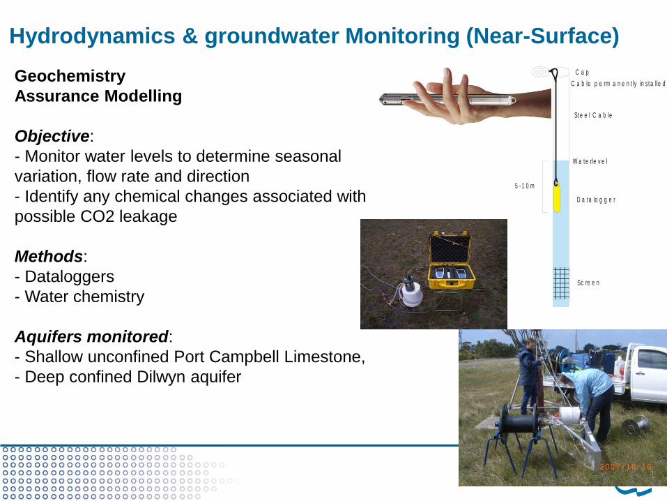
Hydrodynamics & groundwater Monitoring (Near-Surface)
Geochemistry
Assurance Modelling
Objective:
- Monitor water levels to determine seasonal
variation, flow rate and direction
- Identify any chemical changes associated with
possible CO2 leakage
Methods:
- Dataloggers
- Water chemistry
Aquifers monitored:
- Shallow unconfined Port Campbell Limestone,
- Deep confined Dilwyn aquifer
Sc re e n
D a ta lo g g e r
W a te rle v e l
Ste e l C a b le
C a b le p e rm a n e n t ly in st a lle d
C a p
5 - 1 0 m

Soil Gas Monitoring (Surface)
Geochemistry
Assurance surface monitoring
Objective:
- Establish CO2 variations within the extended
area beyond the CO2CRC tenements
- Determine the likely source of origin
- Differentiate natural from injected CO2.
Methods:
- The soil gas program extracts air from the
unsaturated soil zone above the water table.
- Samples are analysed on site (portable gas
chromatograph) and in the laboratory for CO2,
CH4 and isotopes.
Frequency
- Baseline: Four surveys
- Once a year during and after the injection

Atmospheric Monitoring
Objectives:
To verify that injected CO2 stays underground; or in the unlikely event
of leakage to surface, demonstrate the capacity to detect and quantify
surface leakage Otway
Cap Grim

Figure X – U-tube surface facility
(yellow container) – above
Figure X – Isotube sample
cylinder – left
Figure X – Inside the u -tube
surface facility - right
Downhole fluid sampling

Injection phase: U-Tube-2 results
July – minor pH changes,
tracers detected
CO2 arrival
within
modelling
predictions August – significant pH
drop, increase in
dissolved CO2, tracers
peak September – gas lift


Otway Stage 2 – storage in saline aquifers
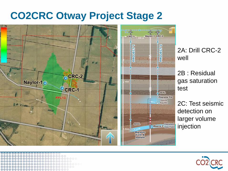
2A: Drill CRC-2
well
2B : Residual
gas saturation
test
2C: Test seismic
detection on
larger volume
injection
CO2CRC Otway Project Stage 2
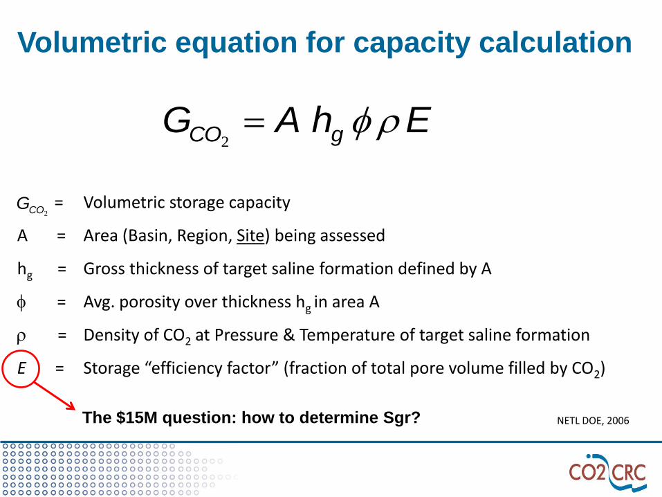
Volumetric equation for capacity calculation
NETL DOE, 2006
= Volumetric storage capacity
A = Area (Basin, Region, Site) being assessed
hg = Gross thickness of target saline formation defined by A
f = Avg. porosity over thickness hg in area A
r = Density of CO2 at Pressure & Temperature of target saline formation
E = Storage “efficiency factor” (fraction of total pore volume filled by CO2)
EhAG gCO rf2
2COG
The $15M question: how to determine Sgr?

Trapping in a saline formation
Residual trapping is where small amounts of CO2 are
disconnected from each other, trapped in the pore space.

Stage 2b – Residual Gas Saturation Test
• Single well injection test evaluating residual CO2 trapping for
potential storage sites
• Applying a suite of five independent tests quantifying
maximum residual gas saturation in saline aquifers
1. Hydraulic pressure test
2. Tracer test
3. Thermal test
4. Measure hydrogen index using a pulsed neutron log (RST)
5. Dissolution test
• Ultimately determining the maximum capacity of a reservoir to
residually trap CO2

2b Test Activity and Timeline

CRC-2 Downhole Completions Equipment

Hydraulic pressure test
• Pressure data are sensitive to residual
gas saturation
• Pressure sensors are installed above
and below the perforation
• Pressure transients are recorded to
infer the amount of gas trapped in the
formation
→Pressure change depends on relative permeability
→Relative permeability depends on residual gas saturation


Noble Gas Tracer Test (Kr-Xe)
• Tracers are injected into the formation with water and then back
produced (U-Tube sampling)
• Noble Gas Tracers partition between aqueous and CO2-rich
phase
• Portions will partition into the gas and become immobile
(hence not produced back)
• Tracers in water remain mobile and are being back produced
→ Measured with GC’s and MS’s in Mobile Geochem Lab
→ Residual saturation can be inferred by comparing Break
Through curves
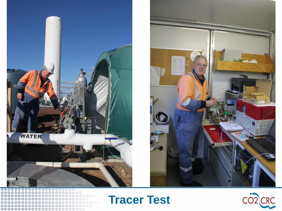
Tracer Test

Tracer Injection

0
200
400
600
800
1000
1200
0 20 40 60 80 100 120 140 160 180
trac
er
pp
m
water production (tonnes)
Kr
Xe
0
50
100
150
200
250
0 20 40 60 80 100 120 140 160 180tr
ace
r p
pm
Water production (tonnes)
Kr
Xe
Baseline Test (100% Pore Water) Residual CO2 Saturated
Kr-Xe Partitioning

Fiber-Optic Distributed Temperature Sensors
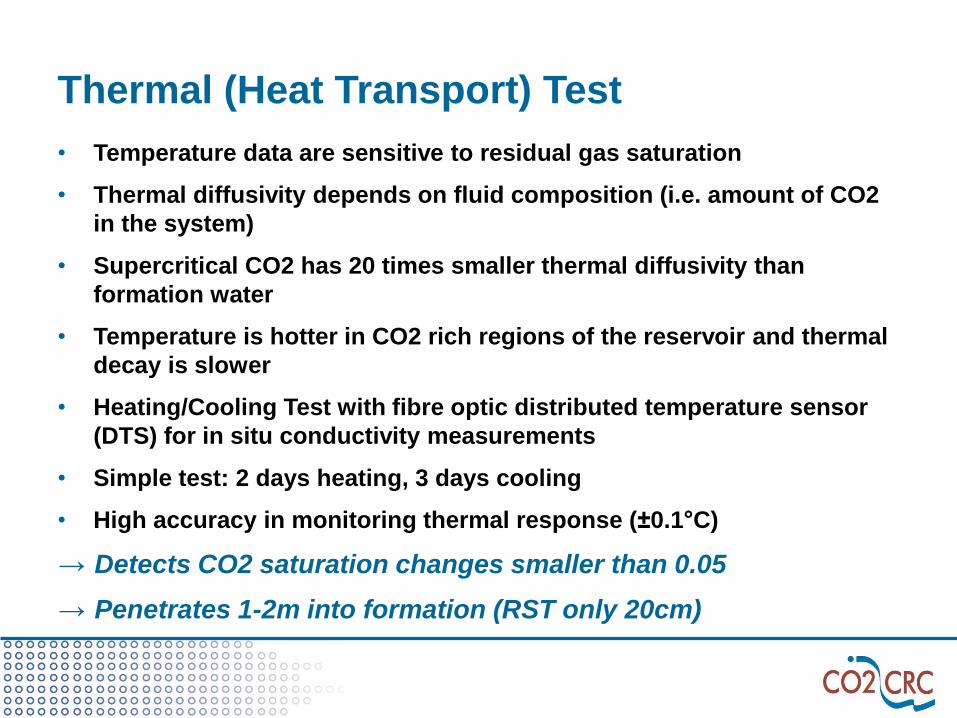
Thermal (Heat Transport) Test
• Temperature data are sensitive to residual gas saturation
• Thermal diffusivity depends on fluid composition (i.e. amount of CO2
in the system)
• Supercritical CO2 has 20 times smaller thermal diffusivity than
formation water
• Temperature is hotter in CO2 rich regions of the reservoir and thermal
decay is slower
• Heating/Cooling Test with fibre optic distributed temperature sensor
(DTS) for in situ conductivity measurements
• Simple test: 2 days heating, 3 days cooling
• High accuracy in monitoring thermal response (±0.1°C)
→ Detects CO2 saturation changes smaller than 0.05
→ Penetrates 1-2m into formation (RST only 20cm)

DTPS Temperature Screen shots

Sgr via pulsed neutron reservoir saturation tool (RST)

RST results TPHI
• CO2 has replaced formation
water
• Ø Sgr is ~20%
• Sgr ~23% in top half of
interval
• Sgr ~18% in bottom half of
interval
• Blue shaded region is CO2
saturation after CO2
injection
• Green shaded region is CO2
saturation after water
injection
Comparison of three RST runs: • Pre injection
• Post CO2 injection
• Post water injection
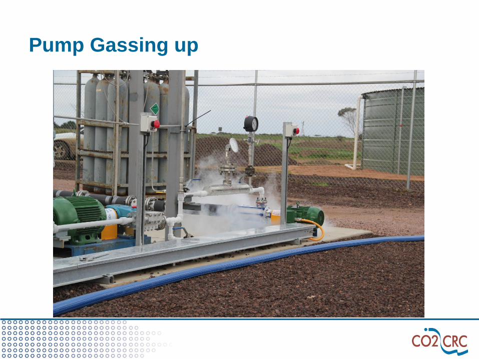
Pump Gassing up

Where from here?
• Preliminary results in Dec 11 at Symposium in Adelaide
• Final data interpretation and report in ca. 12 months
• Blueprint for other storage projects globally
• Controlled release of CO2 for to calibrate atmospheric
monitoring
• Site being mothballed
• In the meantime: 2c progressing through peer review and
regulatory approvals
• Providing continuous advice to national and international
Geological Sequestration Projects
Next research phase: Otway Stage 2c
Research objectives
• Minimum volume of free CO2 to be imaged by 3D seismic (10kt+)
– Demonstration of CO2 dissolution trapping (“diminishing” plume in
seismic image)
• Clear demonstration of CO2 residual trapping in an unconfined structural
trap (i.e. “immobilised” plume)
• Repeated borehole seismic testing whether CO2 plume evolution can be
monitored
• Migration and monitoring forecasts for new large-scale projects
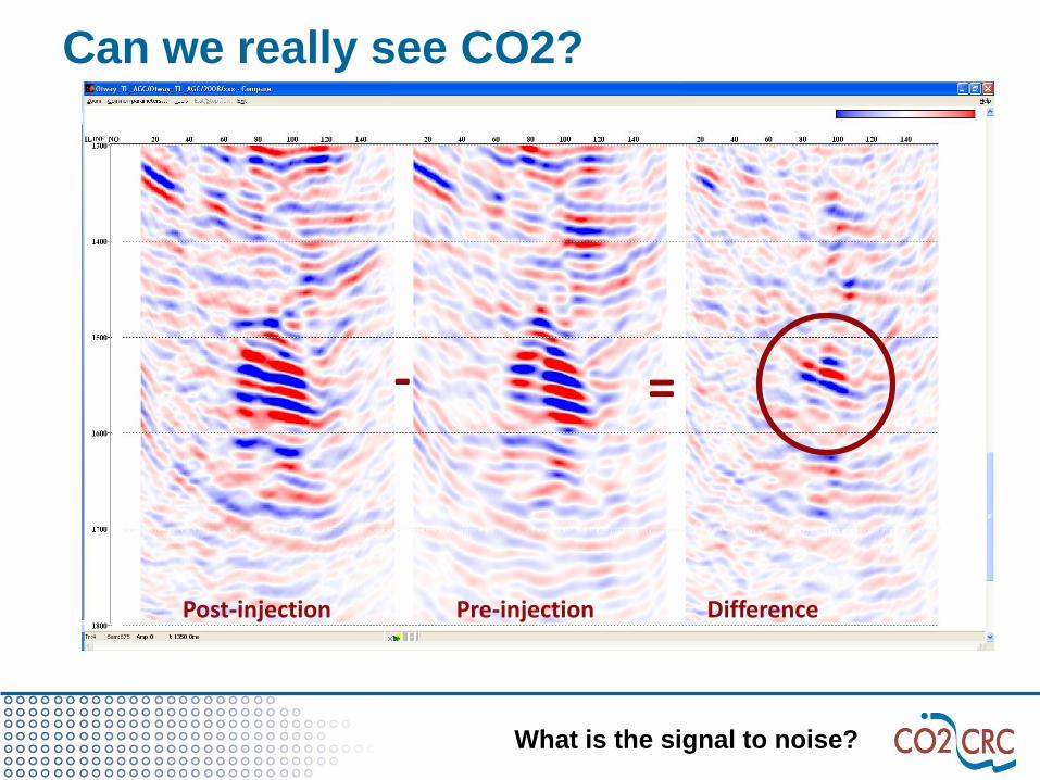
Can we really see CO2?
- =
Post-injection Pre-injection Difference
What is the signal to noise?

Objectives of the simulations
• Understand the migration of 10,000 tonnes
of CO2 injected into the Paaratte saline
aquifer
• Assess the CO2 plume characteristics
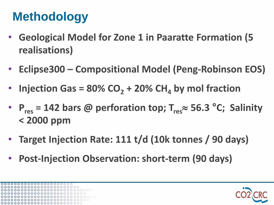
Methodology
• Geological Model for Zone 1 in Paaratte Formation (5 realisations)
• Eclipse300 – Compositional Model (Peng-Robinson EOS)
• Injection Gas = 80% CO2 + 20% CH4 by mol fraction
• Pres = 142 bars @ perforation top; Tres 56.3 °C; Salinity < 2000 ppm
• Target Injection Rate: 111 t/d (10k tonnes / 90 days)
• Post-Injection Observation: short-term (90 days)

Well locations & splay fault
S
N W
E

CO2 plume evolution – case 1
3k tonnes
90d post
6k tonnes
1year post
10k tonnes
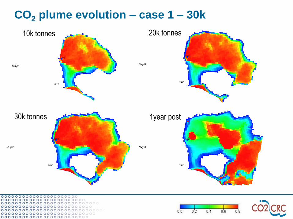
CO2 plume evolution – case 1 – 30k
10k tonnes
30k tonnes
20k tonnes
1year post

Water density– case 1
3k tonnes injected
90 days post-injection 1 year post-injection
10 tonnes injected

Plume characteristics
homogeneous
Case 4
Lateral extension (metres)
Avg. gas saturation
(%)
Avg. plume thickness (meters)
Injected gas inventory (%)
EW NS Free Trap-ped
Dissolved in water
When inj. ceased
400 >430 48 1.8 70 18 12
90-day post injection
500 >430 40 1.8 69 17 14
1-year post-injection
530 > 430 24 2.0 64 16 20
Case - 1
boundary effects in south

The fastest way to finish a project:
Finish it
The waterproof way of killing a project:
Do it slowly

Thank you
CO2CRC would like acknowledge the
Global CCS Institute for the support they
have provided for this presentation

Established & supported under the Australian Government’s Cooperative Research Centres Program
CO2CRC Participants
Supporting Partners: The Global CCS Institute | The University of Queensland | Process Group | Lawrence Berkeley National Laboratory
Government of South Australia | CANSYD Australia | Charles Darwin University | Simon Fraser University