The Clavister cOS Core VPN Cookbook
220
The Clavister cOS Core VPN cookbook Only the tastiest recipes By Peter Nilsson Clavister AB Sweden
Transcript of The Clavister cOS Core VPN Cookbook

The Clavister
cOS CoreVPN cookbookOnly the tastiest recipes
By Peter NilssonClavister AB Sweden

Copyright © 2017 by Peter Nilsson
All rights reserved. This book or any portion thereof may not be reproduced or used in anymanner whatsoever without the express written permission of the publisher except for the use ofbrief quotations in a book review.
Printed by CreateSpace
First Printing, 2017
ISBN: 978-91-982968-4-6
Clavister ABSjögatan 6JSE-89160 ÖrnsköldsvikSweden
www.clavister.com

AcknowledgementsA big thank you for the encouragement and support of the following people in helping to getthis book finished: Neal Sutherland, Torbjörn Fahlen, Fredrick Backman, André Sjöström, KimmoKlemola, Tobias Rhén, Simon Bylund-Felixon and especially Magnus Strödin for being patientwith the constant barrage of questions about all things IPsec.
About the AuthorPeter Nilsson is the team leader for technical support at Clavister AB and has over a decade ofexperience helping enterprise customers set up network security solutions using Clavisterproducts. He lives in Örnsköldsvik, Sweden
iii

iv

Table of ContentsChapter 1: Introduction 71.1. An introduction to VPN – What is it? 9
1.2. Planning VPN 10
Chapter 2: IPsec 152.1. IPsec Explained 16
2.2. IPsec Tunnel Properties 24
Recipe 2.3. A basic IPsec Lan to Lan tunnel scenario 43
Recipe 2.4. Configuring IPsec roaming / road warrior IPsec 69
Recipe 2.5. Configuring IPsec roaming split tunneling with multiple networks. 86
Recipe 2.6. Accessing satellite offices through central HQ using VPN 93
Recipe 2.7. Using Certificates as authentication on a Lan2Lan tunnel 110
Recipe 2.8. Using ID list to separate IPsec tunnels that are behind dynamic IP 132
Recipe 2.9. Making public internet access go through IPsec tunnel towards HQ 142
Chapter 3: L2TPv3 1593.1. An introduction to L2TPv3 159
Recipe 3.2. Bridging a layer 2 network using L2TPv3 & IPsec 162
Recipe 3.3. Bridging a layer 2 VLAN network using L2TPv3 & IPsec 181
Appendix A - Troubleshooting rules and route problems using PingSimulations. 196
Appendix B – IPsec IKE version 1 tunnel setup flowchart. 214
Afterword 216
Alphabetical Index 217
v

vi

7
Chapter 1: Introduction
Welcome to the second Clavister book. In this book our main focus will be VPN (Virtual PrivateNetwork) in various forms, we will mainly focus on IPsec and IPsec scenarios but we will alsocover some scenarios involving L2TPv3 as well as troubleshooting VPNs using ping simulation.
If not yet familiar with Clavister, it is recommended that the first book “The Clavister cOS CoreCookbook” be read first in order to get a fundamental grasp of Clavister and some of ourgeneral principles.

Network diagram icons and screenshotsThroughout the book we will be using network schematics of various scenarios. The variousicons used is shown and described in figure 1.0.1.
Figure 1.0.1 The various icons used throughout the book.
ScreenshotsThis book contains a large amount of screenshots primary taken from the Web User Interface(WebUI) of cOS Core. The screenshots are in most cases taken on a specific feature or function tohighlight their use in the recipe context and may look different depending on what version ofcOS Core that is used. Some pictures may be truncated slightly to make them fit better into thestyle and width of the book and also in an attempt to try limit the size of some screenshots toavoid them filling e.g. an entire page.
The book is based on the graphical style and feature set of cOS Core version 11.20.
8
Chapter 1: Introduction

1.1. An introduction to VPN –What is it?The Internet is increasingly used as a means to connect computers since it offers efficient andinexpensive communication. The requirement therefore exists for data to traverse the Internet toits intended recipient without another party being able to read or alter the integrity of themessage.
It is equally important that the recipient can verify that no one is falsifying data, in other words,pretending to be someone else. Virtual Private Networks (VPNs) meet this need, providing ahighly cost effective means of establishing secure links between two co-operating computers sothat data can be exchanged in a secure manner. VPN allows the setting up of a tunnel betweentwo devices known as tunnel endpoints as shown in figure 1.1.1.
Figure 1.1.1 Connecting two devices together from different parts of the globe. Both sides havetheir own endpoint
All data flowing through a tunnel between the two endpoints is secured using encryption.
Encryption of VPNEncryption of VPN traffic is done using the science of cryptography. Cryptography is an umbrella
Expression, which covers 3 techniques and benefits:
1. Confidentiality
No one but the intended recipients is able to receive and understand the communication.Confidentiality is accomplished by encryption.
9
Chapter 1: Introduction

2. Authentication and Integrity
Proof for the recipient that the communication was actually sent by the expected sender,and that the data has not been modified in transit. This is accomplished by authentication,and is often implemented through the use of cryptographic keyed hashing.
3. Non-repudiation
Proof that the sender actually sent the data; the sender cannot later deny having sent it.Non-repudiation is usually a side-effect of authentication.
VPNs are normally only concerned with confidentiality and authentication. Non-repudiation isnormally not handled at the network level but rather is usually done at a higher, transactionlevel.
1.2. Planning VPNAn attacker, targeting a VPN connection, will typically not attempt to crack the VPN encryptionsince this requires enormous effort. They will, instead, see VPN traffic as an indication that thereis something worth targeting at the other end of the connection. Typically, mobile clients andbranch offices are far more attractive targets than the main corporate network. Once an attackergains access inside mobile clients or branch offices, getting to the corporate network thenbecomes easier. In designing a VPN there are many issues that need to be addressed whicharen't always obvious. These include:
l Protecting mobile and home computers.
l Restricting access through the VPN to needed services only, since mobile computers arevulnerable.
l Creating DMZs for services that need to be shared with other companies through VPNs.
l Adapting VPN access policies for different groups of users.
l Creating key distribution policies.
10
Chapter 1: Introduction

Endpoint SecurityA common misconception is that VPN-connections are equivalent to the internal network from asecurity standpoint and that they can be connected directly to it with no further precautions. It isimportant to remember that although the VPN-connection itself may be secure, the total level ofsecurity is only as high as the security of the tunnel endpoints.
It is becoming increasingly common for users on the move to connect directly to theircompany's network via VPN from their laptops or tablets. However, the client equipment itself isoften not protected. In other words, an intruder can gain access to the protected networkthrough an unprotected laptop and already-opened VPN connections.
Placement in a DMZA VPN connection should never be regarded as an integral part of a protected network. The VPNgateway should instead be located in a special DMZ or outside a gateway dedicated to this task.By doing this, the administrator can restrict which services can be accessed via the VPN andensure that these services are well protected against intruders.
In cases where the router, firewall or gateway features an integrated VPN feature, it is usuallypossible to dictate the types of communication permitted and cOS Core has this feature.
Key DistributionKey distribution schemes are best planned in advance. An example of a key distribution would bethe Pre-shared key or Certificates needed for an IPsec tunnel.
Issues that need to be addressed include:
l How will keys be distributed? Email is not a good solution. Phone conversations might besecure enough.
l How many different keys should be used? One key per user? One per group of users? Oneper LAN-to-LAN connection? One key for all users and one key for all LAN-to-LANconnections? It is probably better using more keys than are necessary today, since it will beeasier to adjust access per user (group) in the future.
11
Chapter 1: Introduction

l Should the keys be changed? If they are changed, how often? In cases where keys areshared by multiple users, consider using overlapping schemes, so that the old keys workfor a short period of time when new keys have been issued.
l What happens when an employee in possession of a key leaves the company? If severalusers are using the same key, it should be changed.
l In cases where the key is not directly programmed into a network unit, such as a VPNgateway, how should the key be stored? On an USB stick? As a pass phrase to memorize?On a smart card? If it is a physical token, how should it be handled?
This means that it is very important to make sure that no unauthorized access can be made to aLaptop, for example, that has the required encryption keys or Certificates installed.
Good Anti-Virus software and strong passwords to access the laptop in question, are prettymuch a requirement in such scenarios.
An example how a third party could gain access to a secure server is shown in figure 1.2.1.
Figure 1.2.1 Very important to secure the system that establishes a VPN tunnel
If we take the scenario in figure 1.2.1 as an example we have a situation where we have anencrypted VPN connection between .e.g. a user’s home PC and a Firewall located in the companythe user works. The user uses the VPN tunnel in order to perform work from home.
12
Chapter 1: Introduction

The user has setup all the necessary VPN keys and encryption algorithms but if the home usersPC get infected by a Trojan, an external third party could gain access to the company server byusing the VPN tunnel already configured and established by the home user.
We will go through some of the common VPN tunnel scenarios as well as describe the variousprinciples and how VPN works and how to apply it in various situations. But no matter howstrong encryption and secure the VPN tunnel is, there may still be weak points in the network if ahome users PC is lacking e.g. anti-virus software.
13
Chapter 1: Introduction

14

15
Chapter 2: IPsec
This section looks at the IPsec standards and describes in general terms the various components,techniques and algorithms that are used in IPsec based VPNs. To jump directly to the firstexample/recipe on how IPsec is configured and scenarios, please see Recipe 2.3. A basic IPsecLan to Lan tunnel scenario.

2.1. IPsec ExplainedIPsec is, simply put, encryption at the network level. Let’s say we have two PC’s that want tocommunicate with each other over the internet. As an example, we want to send a text file fromPC-A to PC-B. This text file contains sensitive information that we do not want to risk beingintercepted by a third party or read by someone unauthorized. By transferring this file over theinternet it must pass through a number of routers, switches etc. and at each step it risksinterception by a third party. The solution is to encapsulate this text file inside an encryptedconnection, shown as a tube in figure 2.1.1.
Figure 2.1.1 Encrypted tunnels can be used to safely transfer sensitive information between twolocations without risk of exposure
The risk of exposing the content of our text file drops significantly by encapsulating thecommunication between the two PC’s in an encrypted tunnel that uses strong encryptionmethods. Even if the traffic were to be intercepted by a third party, it is still rendered unreadableto them and therefore protected by strong encryption algorithms.
16
Chapter 2: IPsec

This defines the basic principle of IPsec, protecting network communication between networks.This also applies for other types of VPN such as PPTP, L2TP and SSL-VPN but the mostcommonly used method of creating encrypted tunnels is IPsec due to its very strong encryptioncapability.
Detailed information about IPsec its componentsInternet Protocol Security (IPsec) is a set of protocols defined by the Internet Engineering TaskForce (IETF) to provide IP security at the network layer. An IPsec based VPN is made up of twoparts:
l Internet Key Exchange protocol (IKE)
l IPsec protocols (ESP)
The first part, IKE, is the initial negotiation phase, where the two VPN endpoints agree on whichmethods will be used to provide security for the underlying IP traffic. Furthermore, IKE is used tomanage connections, by defining a set of Security Associations, SAs, for each connection. SAs areunidirectional, so there are usually at least two for each IPsec connection. The second part is theactual IP data being transferred, using the encryption and authentication methods agreed uponin the IKE negotiation. This can be accomplished by using IPsec protocol ESP (EncapsulatingSecurity Payload).
The flow of events can be briefly described as follows:
l IKE negotiates how IKE should be protected
l IKE negotiates how IPsec should be protected
l IPsec moves data in the VPN
17
Chapter 2: IPsec
Internet Key Exchange (IKE)Encrypting and authenticating data is fairly straightforward, the only things needed areencryption and authentication algorithms, and the keys used with them. IKE is used as a methodof distributing these "session keys" between the two tunnel endpoints, as well as providing away for the VPN endpoints to agree on how the data should be protected.
A session key is a pair of keys negotiated between the tunnel endpoints that will be used toencrypt data.
IKE has three main tasks:
l Provide a means for the endpoints to authenticate each other
l Establish new IPsec connections (create SA pairs)
l Manage existing connections
IKE is a protocol that belongs to the IPsec protocols suite. Its responsibility is in setting upsecurity associations that allow two parties to send data securely. IKE was introduced in 1998and was later superseded by version 2 roughly 7 years later. There are a number of differencesbetween IKEv1 and IKEv2. Without going into too much detail, here is a small list of some of theenhancements in IKEv2 compared to IKEv1:
l IKEv2 less bandwidth usage
l IKEv2 supports EAP (Extensible Authentication Protocol) authenticationo EAP is an authentication framework frequently used in wireless networks and point-to-point connections
l IKEv2 MOBIKE supporto MOBILE (Mobility and Multihoming Protocol) support, provides a means for aroaming client to change IP address as it switches from one network to another
l IKEv2 built-in NAT traversal supporto This applies for IKEv1 as well but not natively
18
Chapter 2: IPsec

l IKEv2 can by default detect whether a tunnel is still alive or noto This applies for IKEv1 as well but not natively
Security Associations (SAs)IKE keeps track of connections by assigning a set of Security Associations, SAs, to eachconnection. An SA describes all parameters associated with a particular connection, such as theIPsec protocol used (ESP/AH/both) as well as the session keys used to encrypt/decrypt and/orauthenticate/verify the transmitted data.
An SA is unidirectional and relates to traffic flow in one direction only. For the bidirectional trafficthat is usually found in a VPN, there is therefore a need for more than one SA per connection. Inmost cases two SAs will be created for each connection, one for the incoming traffic, and theother the outgoing.
NoteThis routing table will look different depending on the amount of interfaces and thehardware platform.
IKE NegotiationThe process of negotiating session parameters consists of a number of phases and modes. Theflow of events can be summarized as follows:
IKE Phase-1
l Negotiate how IKE should be protected
IKE Phase-2
l Negotiate how IPsec should be protected
l Derive some fresh keying material from the key exchange in phase-1, to provide sessionkeys to be used in the encryption and authentication of the VPN data flow
19
Chapter 2: IPsec

IKE and IPsec LifetimesBoth the IKE and the IPsec connections have limited lifetimes. Both are described in terms of time(seconds), and data (kilobytes). These lifetimes prevent a connection from being used for toolong, which is desirable from a crypto-analysis perspective. Meaning that if someone wants todecrypt the data after a re-key, they have to start all over again as new encryption keys havebeen generated.
The IPsec lifetime must be shorter than the IKE lifetime. The difference between the two must bea minimum of 5 minutes. This allows for the IPsec connection to be re-keyed simply byperforming another phase-2 negotiation. There is no need to do another phase-1 negotiationuntil the IKE lifetime has expired.
Lifetime RecommendationsIt is recommended that the lifetime values are equal to or greater than the following values:
l IKE lifetime - 600 seconds (10 minutes)
l IPsec lifetime - 300 seconds (5 minutes)
IPsec lifetime - 300 seconds (5 minutes)
If the administrator uses values which are less, cOS Core will accept them but a warningmessage will be presented during the reconfiguration.
Please keep in mind that this is the minimum value. It is not recommended to use such lowvalues on active tunnels at it means that both IKE and IPsec SA’s will re-key very often. Anddepending on key-length* used and the power of the hardware used it could cause trafficdisturbances when the system needs to generate new encryption keys. A common lifetime to usefor IKE is 28800 seconds (8 hours) and 3600 seconds for IPsec (1 hour).
*An example of key-length would be for instance using the AES algorithm with a 256 bit key size.AES can use 128, 192 and 256 bit keys. It varies depending on encryption algorithm.
20
Chapter 2: IPsec

IKE Algorithm ProposalsAn IKE algorithm proposal list is a suggestion of how to protect IKE and IPsec data flows. TheVPN device initiating an IPsec connection, usually called the initiator, will send a list of thealgorithms combinations it supports for protecting the connection and it is then up to the deviceat the other end of the connection, usually called the responder, to say which proposal isacceptable.
The responding VPN device, upon receiving the list of supported algorithms, will choose thealgorithm combination that best matches its own security policies, and reply by specifying whichmember of the list it has chosen. If no mutually acceptable proposal can be found, the responderwill reply by saying that nothing on the list was acceptable, and possibly also provide a hint orclue as to what the problem could be.
This negotiation to find a mutually acceptable algorithm combination is done not just to find thebest way to protect the IPsec connection but also to find the best way to protect the IKEnegotiation itself. Algorithm proposal lists contain not just the acceptable algorithmcombinations for encrypting and authenticating data but also other IKE related parameters.Further details of the IKE negotiation and the other IKE parameters are described next.
IKE Phase-1 - IKE Security NegotiationAn IKE negotiation is performed in two phases. The first phase, phase 1, is used to authenticatethe two VPN gateways or VPN Clients to each other, by confirming that the remote device has amatching Pre-Shared Key (or provides a matching/valid Certificate).
However, since we do not want to publish too much of the negotiation in plaintext, we first agreeupon a way of protecting the rest of the IKE negotiation. This is done, as described in theprevious section, by the initiator sending a proposal-list to the responder.
When this has been done, and the responder accepted one of the proposals, the initiator tries toauthenticate the other end of the VPN to make sure it is who we think it is, as well as proving tothe remote device that we are who we claim to be.
A technique known as a Diffie Hellman Key Exchange is used to initially agree a shared secretbetween the two parties in the negotiation and to derive keys for encryption.
21
Chapter 2: IPsec

Authentication can be accomplished through Pre-Shared Keys (PSK), certificates or public keyencryption. Pre-Shared Keys is the most common authentication method today. PSK andcertificates are supported by the cOS Core VPN module.
IKE Phase-2 - IPsec Security NegotiationIn phase 2, another negotiation is performed, detailing the parameters for the IPsec connection.During phase 2 we will also repeatedly extract new keying material from the Diffie-Hellman keyexchange in phase 1 in order to provide fresh session keys to use in protecting the VPN dataflow.
Perfect Forward Secrecy (PFS)
If PFS is used, a new Diffie-Hellman exchange is performed for each phase 2 negotiation. Whilethis is slower, it makes sure that no keys are dependent on any other previously used keys; nokeys are extracted from the same initial keying material. This is to make sure that, in the unlikelyevent that some key was compromised, no subsequent keys can be derived.
In cryptography PFS is a property of key-agreement protocols ensuring that a session keyderived from a set of long-term keys cannot be compromised if one of the long-term keys iscompromised in the future. The key used to protect transmission of data must not be used toderive any additional keys, and if the key used to protect transmission of data is derived fromsome other keying material, then that material must not be used to derive any more keys.
In this way, compromise of a single key permits access only to data protected by that single key.
Once the phase 2 negotiation is finished, the VPN connection is established and ready for trafficto pass through it.
IKE and IPsec negotiation can operate in two modes called Main and Aggressive modes. Asimplified picture on the Main Mode is shown in figure 2.1.2. We will discuss Main andAggressive mode in more detail later in the book.
22
Chapter 2: IPsec

Figure 2.1.2 IKE and IPsec negotiation between initiator and responder (sometimes known asterminator) in Main Mode
23
Chapter 2: IPsec

2.2. IPsec Tunnel PropertiesBelow, is a summary of the key properties required of an IPsec tunnel object. Many of theseoptions and settings will be explained in various contexts as we progress in the IPsec relatedrecipes, this part is mainly to be used as reference as it can be a bit overwhelming if read as awhole.
Local and Remote Networks/HostsThese are the subnets or hosts between which IP traffic will be protected by the VPN. In a LAN-to-LAN connection, these will be the network addresses of the respective LANs. If roamingclients are used, the remote network will most likely be set to all-nets, meaning that the roamingclient may connect from anywhere.
The most common VPN is where we connect two sites together (usually called Lan2Lan) or whenthere is a client/server solution where a VPN client connects to a VPN server to access resources,the client/server solution is commonly called Roaming or Roadwarrior.
Local ID and Remote IDThe local and remote IDs are values sent by the corresponding sides of the tunnel during the IKEnegotiation and both can be used with either a pre-shared key or certificate based tunnel.
Local ID
This property of an IPsec Tunnel object represents the identity of the local VPN tunnel endpointand this is the value presented to the remote peer during the IKE negotiation. The property is setto only a single value but can be left blank when using certificates since the ID will be containedwithin the host certificate. If the certificate contains multiple IDs, this property can be set tospecify which ID in the certificate to use.
The “Enforce Local ID”-property can be enabled so that when cOS Core is acting as responder,the local ID proposed by the initiator must match the Local ID value on the responder. Thedefault behavior is to ignore the proposed ID.
24
Chapter 2: IPsec

Remote ID
This property can be used to specify an ID list object. An ID list object contains one or more IDs.When using certificates, the certificate sent by a remote peer must contain an ID which matchesone of the IDs in the list in order for the peer to be authenticated.
cOS Core applies sanity checks on all remote IDs to ensure they are acceptable. Usuallymalformed IDs have a problem in the OU name. For example, a faulty remote ID name might bethe following:
DN=Clavister, OU=One,Two,Three, DC=SE
If specified by the administrator, there will be an error message when the cOS Coreconfiguration is committed. The corrected remote ID form is the following:
DN=Clavister, OU=One\,Two\,Three, DC=SE
We will go into more details about certificates later in this chapter.
Encapsulation ModeIPsec can be configured using two modes:
Mode-1 - Tunnel Mode.IPsec tunnel mode is the default mode. With tunnel mode, the entire original IP packet isprotected by IPsec. This means IPsec takes the entire original packet, encrypts it, adds a new IPheader and sends it to the other side of the IPsec tunnel (Remote Endpoint).
Tunnel mode is most commonly used between gateways (e.g. two Clavister firewalls or otherIPsec capable gateways/routers).
In tunnel mode, an IPsec header (AH or ESP header) is inserted between the IP header and theupper layer protocol. ESP and ESP Auth trailer is the same for both Tunnel & Transport mode.
NoteESP= Encapsulating Security Payload and AH=Authentication Header.
25
Chapter 2: IPsec

Between AH and ESP, ESP is most commonly used in IPsec VPN Tunnel configuration. Figure2.2.1 shows IPsec Tunnel mode with ESP header.
NotecOS Core only supports ESP headers, AH is not supported. When IPsec was originallydesigned, computer power was far less than it is today, particularly in network devices,the idea was to have two protocols that could be used independently or in conjunctionin order to better manage the computer resources (and thus, performance) moreeffectively.
AH by itself was intended for cases where secrecy wasn't required but we wanted to ensure theauthenticity of the sender. Imagine routing protocol updates such as DNS or SNMP where thedata isn't secret but you want to be sure the sender is who they claim to be.
ESP by itself was intended for secrecy of the payload and has enough integrity features that itdoes not really need AH. Due to the high requirements of encryption, AH was neverimplemented as an option in cOS Core due to its lack of strong encryption capabilities. It is veryrare to encounter IPsec capable equipment with only support for AH in today’s network securitymarket.
Figure 2.2.1 Tunnel mode ESP header
26
Chapter 2: IPsec

Mode-2 - Transport Mode
IPsec Transport mode is used for end-to-end communications, for example, for communicationbetween a client and a server or between a workstation and a gateway (if the gateway is beingtreated as a host).
Transport mode provides the protection of data, also known as IP Payload, and consists ofTCP/UDP header + Data, through an AH or ESP header. The payload is encapsulated by the IPsecheaders and trailers. The original IP headers remain intact, except that the IP protocol field ischanged to ESP (IP protocol 50) or AH (IP protocol 51), and the original protocol value is saved inthe ESP trailer to be restored when the packet is decrypted.
NoteESP trailer consists of the Padding, Pad Length, and Next Header fields.
IPsec transport mode is usually used when another tunneling protocol (like GRE) is used to firstencapsulate the IP data packet, then IPsec is used to protect the GRE tunnel packets. IPsecprotects the GRE tunnel traffic in transport mode. Figure 2.2.2 shows IPsec Transport mode withESP header.
Figure 2.2.2 Transport mode ESP header
Notice that the original IP Header is moved to the front. Placing the sender’s IP header at thefront (with minor changes to the protocol ID) proves that transport mode does not provideprotection or encryption to the original IP header.
ESP is identified in the New IP header with an IP protocol ID of 50.
27
Chapter 2: IPsec

Remote EndpointThe remote endpoint (sometimes also referred to as the remote gateway) is the remote deviceon the other side of the tunnel that does the VPN decryption/authentication of the data that wesend through the tunnel and that passes the unencrypted data on to its final destination.Basically the machine we would like to setup an encrypted tunnel against.
Figure 2.2.3 A tunnel endpoint means the point a tunnel is connected to. This is true for both sides,although varies slightly in case of a client/server solution
This field can also be set to “none”, forcing the Clavister Security Gateway to treat the remote IPaddress as the remote endpoint. This is particularly useful in cases of roaming access, where theIP addresses of the remote VPN clients are not known beforehand. Setting this option to "none"will allow anyone coming from an IP address conforming to the "remote network" addressdiscussed above to open a VPN connection, provided they can authenticate properly.
The remote endpoint can be specified as a host name such as vpn.example.com. If this is done,the prefix dns: must be used. The string above should therefore be specified asdns:vpn.example.com.
Using DNS can be advantageous in scenarios where the target remote endpoint is behind adynamic IP.
NoteThe remote endpoint option is not applicable in transport mode.
28
Chapter 2: IPsec

Main/Aggressive ModeThe IKE negotiation has two modes of operation, main mode and aggressive mode. Thedifference between these two is that aggressive mode consists of fewer packet exchanges.Aggressive mode does not give identity protection of the two IKE peers, unless digital certificatesare used. This means VPN peers exchange their identities without encryption (i.e. in clear text). Itis not as secure as main mode, but the advantage to aggressive mode is that it is faster thanMain mode.
Main Mode creates an encrypted channel before exchanging the identities.
Aggressive Mode exchanges endpoint IDs in “clear text”, while performing DH (Diffie Hellman)exchange and establishing the secure channel. Aggressive mode is less secure than Main Modeand should be less preferred.
NoteIt is recommended NOT to use aggressive mode in roaming/roadwarrior scenarios forIKE version 1. The reason for this is the system becomes vulnerable to an IKEamplification attack. Using either tunnel mode or IKE version 2 is stronglyrecommended in roaming/roadwarrior scenarios.
Going into details about the differences between Main mode and Aggressive quickly becomescomplicated. To put it bluntly, using Aggressive mode is less secure but goes faster tonegotiate/establish the VPN tunnel. This is however a rare problem in today’s networkenvironment with very fast computers and internet speeds.
Main mode should be used whenever possible.
29
Chapter 2: IPsec

IPsec ProtocolsThe IPsec protocols describe how the payload data will be processed. The two protocols tochoose from are AH, Authentication Header, and ESP, Encapsulating Security Payload. ESPprovides encryption, authentication, or both. However, it is not recommended to use encryptiononly, since it will dramatically decrease security.
Note that AH only provides authentication. The difference from ESP with authentication only isthat AH also authenticates parts of the outer IP header, for instance source and destinationaddresses, making certain that the packet really came from who the IP header claims it is from.
NotecOS Core does not support AH.
IKE and IPsec EncryptionThis specifies the encryption algorithms that can be used in the IKE and IPsec negotiationsrespectively, and depending on the algorithms, the size of the encryption keys used. Thealgorithms supported by cOS Core is as follows:
l AES
l Blowfish
l Twofish
l Cast128
l 3DES
l DES
DES is only included to be compatible with other older VPN implementations. The use of DESshould be avoided whenever possible since it is considered insecure.
30
Chapter 2: IPsec

IKE and IPsec AuthenticationThis specifies the authentication algorithms that can be used in the IKE and IPsec negotiationphase. The algorithms supported by cOS Core is as follows:
l MD5
l SHA1
l SHA256
l SHA512
l AES-XCBC (IKEv2 only)
MD5 is considered insecure and should not be used, SHA1 is still OK to use at the time this iswritten but the recommendation is to use SHA-256, SHA-512 or AES-XCBC (if IKEv2).
IKE DH GroupThis specifies the Diffie-Hellman group to use for the IKE exchange. cOS Core supports DHgroups of various strengths ranging from group 1 with 768-bit up to group 18 that uses 8192bit. Raising the group number from the default (group 2 – 1024 bit) should be done with cautionas more computing resources will be used for higher group numbers and could lead tounacceptable tunnel setup times on slower hardware platforms.
IKE LifetimeThis refers to the lifetime of the IKE connection. It is specified in time (seconds) as well as dataamount in kilobytes, specifying a lifetime in kilobytes is optional. Whenever one of these expires,a new phase-1 exchange will be performed. If no data was transmitted in the last "incarnation" ofthe IKE connection, no new connection will be made until someone wants to use the VPNconnection again. This value must be set greater than the IPsec SA lifetime.
31
Chapter 2: IPsec

PFSWith Perfect Forwarding Secrecy (PFS) disabled, initial keying material is "created" during the keyexchange in phase-1 of the IKE negotiation. In phase-2 of the IKE negotiation, encryption andauthentication session keys will be extracted from this initial keying material. By using PFS,completely new keying material will always be created upon re-key. Should one key becompromised, no other key can be derived using that information.
PFS can be used in two modes: the first is PFS on keys, where a new key exchange will beperformed in every phase-2 negotiation. The other type is PFS on identities, where the identitiesare also protected, by deleting the phase-1 SA every time a phase-2 negotiation has beenfinished, making sure no more than one phase-2 negotiation is encrypted using the same key.
IPsec LifetimeThis is the lifetime of the VPN connection. It can be specified in both time (seconds) and dataamount (optional value in kilobytes). Whenever either of these values is exceeded, a re-key willbe initiated, providing new IPsec encryption and authentication session keys. If the VPNconnection has not been used during the last re-key period, the connection will be terminated,and re-opened from scratch when the connection is needed again (e.g. when a PC attempts toconnect to a resource through the encrypted tunnel).
This value must be set lower than the IKE lifetime.
Diffie-Hellman GroupsDiffie-Hellman (DH) is a cryptographic protocol that allows two parties that have no priorknowledge of each other to establish a shared secret key over an insecure communicationschannel through a series of plain text exchanges. Even though the exchanges between the partiesmight be monitored by a third party, the Diffie-Hellman technique makes it extremely difficultfor the third party to determine what the agreed shared secret key is and decrypt data that isencrypted using that key.
Diffie-Hellman is used to establish the shared secret keys for IKE, IPsec and PFS in cOS Core. Thehigher the group number (and in turn key-length/strength), the greater the security, but this willalso increase the hardware processing resources required.
The DH groups supported by cOS Core are as follows:
32
Chapter 2: IPsec

l DH group 1 (768-bit).
l DH group 2 (1024-bit - the default setting).
l DH group 5 (1536-bit).
l DH group 14 (2048-bit).
l DH group 15 (3072-bit).
l DH group 16 (4096-bit).
l DH group 17 (6144-bit).
l DH group 18 (8192-bit).
WarningHigher DH group numbers (above group 15) will consume a lot of CPU resources. Mosthardware platforms will be able to provide sufficient processing resources for thedefault DH group 2. Higher group numbers will consume progressively more resourcesand this can mean that tunnel setup for the highest groups can be unacceptably long(tens of seconds) on a slower hardware platform. It could also result in 100% processorutilization from the tunnel setup process and a possible temporary halt of all trafficthroughput.
IKE AuthenticationcOS Core supports two methods of authentication:
l Pre Shared Key (PSK)
l Certificates
33
Chapter 2: IPsec

PSKUsing a pre-shared key (PSK) is a method where the endpoints of the VPN "share" a secret key.This is a service provided by IKE, and thus has all the advantages that come with it, making it farmore flexible than manual keying.
PSK Advantages
The main advantage of PSK is that it is very easy to configure and setup. Compared toCertificates it can be configured in seconds and does not require any third party programs orsolutions.
PSK Disadvantages
One thing that has to be considered when using pre-shared keys is key distribution. How are thePre-Shared Keys distributed to remote VPN clients and gateways? This is a major issue, since thesecurity of a PSK system is based on the PSKs being secret. Should one PSK be compromised, theconfiguration will need to be changed to use a new PSK. The pre-shared key can also beconfigured using a very simple passphrase (such as “test123”), useful for testing purposes butvery insecure if used in a live environment.
CertificatesEach VPN gateway has its own certificate, and one or more trusted root certificates. Theauthentication is based on two things:
l That each endpoint has the private key corresponding to the public key found in itscertificate, and that nobody else has access to the private key.
l That the certificate has been signed by someone that the remote endpoint trusts.
Advantages of Certificates
The main advantage of certificates is added flexibility. Many VPN clients, for instance, can bemanaged without having the same pre-shared key configured on all of them, which is often thecase when using pre-shared keys with roaming clients. Instead, should a client be compromised,the client's certificate can simply be revoked. No need to reconfigure every client.
34
Chapter 2: IPsec

Disadvantages of Certificates
The main disadvantage of certificates is the added complexity. Certificate-based authenticationmay be used as part of a larger public key infrastructure, making all VPN clients and gatewaysdependent on third parties. There are many settings and options available to certificates whichcould make the initial configuration and setup cumbersome to get it working according tospecifications.
Any problems with Certificate based tunnels usually require quite a lot of troubleshooting anddocumentation examination to get it to work properly. The main problem is usually not on cOSCore but rather the third party CA server (or similar) and the many options and settings.
IPsec tunnel protocol ESP (Encapsulating Security Payload)In IPsec ESP provides origin authenticity, integrity and confidentiality protection of packets. ESPalso supports encryption-only and authentication-only configurations, but using encryptionwithout authentication is strongly discouraged. Unlike Authentication Header (AH), ESP intransport mode does not provide integrity and authentication for the entire IP packet. Whenusing Tunnel Mode the entire original IP packet is encapsulated with a new packet header added.ESP protection is provided for the whole inner IP packet (including the inner header) while theouter header (including any outer IPv4 options or IPv6 extension headers) remains unprotected.ESP operates directly on top of IP, using IP protocol number 50.
A detailed overview of ESP when used in tunnel or transport mode is shown in figure 2.2.4
35
Chapter 2: IPsec

Figure 2.2.4 ESP tunnel/transport mode overview (also see figure 2.2.1 and 2.2.2 for details)
ESP only authenticates the data after the ESP header; thus the outer IP header is left unprotected.The ESP protocol is used for both encryption and authentication of the IP packet. It can also beused to do either encryption only, or authentication only.
NAT TraversalBoth IKE and IPsec protocols present a problem in the functioning of NAT (Network AddressTranslation). Both protocols were not designed to function with NAT and because of this, thetechnique called NAT traversal has evolved (also known as NAT-T). NAT traversal is an add-on tothe IKE and IPsec protocols that allows them to function when being NATed. cOS Core supportsthe RFC 3947 standard for NAT-Traversal with IKE. An example of a NAT scenario is shown infigure 2.2.5.
36
Chapter 2: IPsec

Figure 2.2.5 NAT-T needs to be used if the connecting client is behind a NAT’ing device such as arouter
NAT traversal is divided into two parts:
l Extensions to IKE that lets IPsec peers tell each other that they support NAT traversal, andthe specific version(s) of NAT it supports.
l Changes to the ESP encapsulation. If NAT traversal is used, ESP is encapsulated in UDP,which allows for more flexible NATing.
Below, is a more detailed description of the changes made to the IKE and IPsec protocols. NATtraversal is only used if both ends have support for it. For this purpose, NAT traversal aware VPNdevices send out a special "vendor ID" to tell the other end of the tunnel that it understands NATtraversal, and which specific versions of the draft it supports.
Achieving NAT Detection
To achieve NAT detection both IPsec peers send hashes of their own IP addresses along with thesource UDP port used in the IKE negotiations. This information is used to see whether the IPaddress and source port that each peer uses is the same as what the other peer sees. If thesource address and port have not changed, then the traffic has not been NATed along the way,and NAT traversal is not necessary. If the source address and/or port have changed, then thetraffic has been NATed, and NAT traversal is used.
Changing Ports once NAT has been detected
Once the IPsec peers have decided that NAT traversal is necessary, the IKE negotiation is movedaway from UDP port 500 to port 4500.
37
Chapter 2: IPsec

NoteIPsec negotiations always start using UDP port 500 and later in the negotiation move onto use the NAT-T port (4500) or IP protocol 50 (ESP).
Changing the port is necessary since certain NAT devices treat UDP packet on port 500differently from other UDP packets in an effort to work around the NAT problems with IKE.
UDP Encapsulation
Another problem that NAT traversal resolves is that the ESP protocol is an IP protocol (IPprotocol ID 50). There is no port information as we have in TCP and UDP, which makes itimpossible to have more than one NATed client connected to the same remote gateway and atthe same time. Because of this, ESP packets are encapsulated in UDP. ESP-UDP traffic is sent onport 4500, the same port as IKE when NAT traversal is used. Once the port has been changed, allfollowing IKE communication is done over port 4500. NAT keep-alive packets are also sentperiodically to keep the NAT mapping alive.
NoteEnforcing NAT-T can sometimes solve certain scenarios if IP protocol 50 is blocked bysome equipment between the tunnel endpoints. By changing to UDP the problem can insome cases be bypassed.
NAT Traversal Configuration
Most NAT traversal functionality is completely automatic and in the initiating gateway no specialconfiguration is needed. However, for responding gateways two points should be noted:
38
Chapter 2: IPsec

l On responding gateways, the Remote Endpoint field is used as a filter on the source IP ofreceived IKE packets. This should be set to allow the NATed IP address of the initiator.
l When individual pre-shared keys are used with multiple tunnels connecting to the sameremote gateway which are then NATed out through the same address, it is important tomake sure the Local ID property of an IPsec Tunnel object is unique for the tunnel of everyconnecting client and takes one of the following values:
i. Auto - The local ID becomes the IP address of the outgoing interface. This is therecommended setting unless the two gateways have the same external IP address.
ii. IP - An IP address can be manually entered.
iii. DNS - A DNS address can be manually entered.
iv. Email - An email address can be manually entered.
Basically the connecting clients must have some sort of unique identifier that can separatethe different clients. Otherwise the terminating gateway will be unable to properly matchthe connecting clients and it could result in traffic disruptions if the sessions start to bemixed up.
Algorithm Proposal ListsTo agree on the VPN connection parameters, a negotiation process is performed. As a result ofthe negotiations, the IKE and IPsec security associations (SAs) are established. A proposal list ofsupported algorithms is the starting point for the negotiation. Each entry in the list definesparameters for a supported algorithm that the VPN tunnel endpoint device is capable ofsupporting. The initial negotiation attempts to agree on a set of algorithms that the endpointdevices at either end of the tunnel can support.
There are two types of proposal lists, IKE proposal lists and IPsec proposal lists. IKE lists are usedduring IKE Phase-1 (IKE Security Negotiation), while IPsec lists are using during IKE Phase-2(IPsec Security Negotiation). Several algorithm proposal lists are already defined by default incOS Core for different VPN scenarios and a custom user defined list can also be created andused.
39
Chapter 2: IPsec

Pre-shared KeysPre-Shared Keys (commonly known as PSK) are used to authenticate VPN tunnels. The keys aresecrets that are shared by the communicating parties before communication takes place. Tocommunicate, both parties prove to each other that they know the secret. The security of ashared secret depends on how "good" a passphrase is. Passphrases that are common words canbe vulnerable to dictionary attacks.
The PSK is not sent or exposed in the tunnel negotiation as that would void the whole purpose,but to provide an example of roughly how it works:
1. The initiator of the IPsec tunnel sends a packet with data to the remote endpoint.
1.1. The initiator also makes a hash out of the data packet using its PSK.
2. The remote endpoint takes the data and makes a hash out it using its PSK and sends it backto the initiator.
3. The initiator takes the packet and compares the hashed data using its own hashed datapacket. If the two packets are identical it means that the PSK is the same and the tunnelnegotiation can proceed into the next phase.
Please note that this is an overly simplified example, the process is much more complex thanthis.
Random Pre-shared Keys can be generated automatically through the Web Interface but theycan also be generated through the CLI using the command “pskgen”.
40
Chapter 2: IPsec

WarningBeware of Non-ASCII Characters in a PSK on Different Platforms!
If a PSK is specified as a passphrase and not a hexadecimal value, the differentencodings on different platforms can cause a problem with non-ASCII characters.Windows, for example, encodes pre-shared keys containing non ASCII characters inUTF-16 while cOS Core uses UTF-8. Even though they can seem the same at either endof the tunnel there will be a mismatch and this can sometimes cause problems whensetting up a Windows L2TP client that connects to cOS Core.
Using ID Lists with Certificates
A Typical Scenario
Consider the scenario of traveling employees being given access to the internal corporatenetworks using IPsec with certificates. The organization administers their own CertificateAuthority (CA), and certificates have been issued to the employees. Different groups ofemployees are likely to have access to different parts of the internal networks. For example,members of the sales force might access servers running the order system, while technicalengineers would access technical databases.
The Problem
Since the IP addresses of the traveling employees VPN clients cannot be known beforehand, theincoming IPsec connections from clients cannot be differentiated. This means that the securitygateway is unable to correctly administer access to different parts of the internal networks usingonly the client's IP address.
The ID List Solution
One possible solution to this problem is to use Identification lists (ID lists). A cOS Core ID Listobject contains one or more ID objects as children. An IPsec Tunnel object can then have its
41
Chapter 2: IPsec

Remote ID property set to an ID list object. For a particular tunnel to be used by a particularclient, the following must be true:
l The ID sent by the remote client must match one of the IDs in the ID list for the tunnel.
l The ID sent by the remote client must also exist as one of the IDs in the certificate the clientsends.
When the client connects, cOS Core chooses the IPsec Tunnel object to use as follows:
l The connecting client sends its ID to cOS Core in the IKE negotiation.
l cOS Core scans its list of IPsec Tunnel objects looking for a match for the client.
l As an additional part of the matching process, cOS Core also checks the ID the client sendsagainst the ID List of the tunnel. If it does not find an ID match, it continues searchingthrough the IPsec Tunnel list. Any malformed IDs will be ignored and will also generate logmessage warnings.
l Once the matching tunnel is found, cOS Core then checks that the certificate the clientsends also contains this same ID. If the certificate does, authentication is complete and thetunnel can be established. If the ID is not in the certificate, cOS Core flags that there is anauthentication failure and the client connection is dropped.
This means that a particular IPsec Tunnel is only used by a particular client. The cOS Coreconfiguration's IP rules and IP policies can then be designed to control which traffic can flow
through which tunnel (the tunnel being an interface in the rule or policy)
Please note that this is one way to solve a differentiated user/tunnel scenario, there are otherways to solve this scenario as well.
42
Chapter 2: IPsec

Recipe 2.3. A basic IPsec Lan to Lan tunnel scenario
ObjectiveThis is the first recipe, in which we will launch into the IPsec topic by configuring an encryptedLan to Lan tunnel (also referred to as Lan2Lan or L2L) between two cOS Core firewalls. To keepthings simple we will be using pre-shared keys as authentication in many of the initial recipes.We will later move on to describe the use of Certificates as authentication as well. In this recipewe will also go through all the various settings that exists on an IPsec tunnel interface. Thisrecipe can be used as a reference if more information is needed about a specific IPsec interfacesetting or option.
In this scenario we want to setup an IPsec Lan2Lan tunnel between Stockholm and London inorder for devices/machines in Stockholm to talk to units/machines in London and vice versa. Anoverview of the scenario and the networks used is shown in figure 2.3.1.
Figure 2.3.1 Adding a new IPsec tunnel interface
43
Chapter 2: IPsec

Detailed Discussion
RequirementsFor this first recipe, we have three requirements that need to be completed.
l Users in London should have unrestricted access to Stockholm’s local network through theencrypted IPsec tunnel.
l Users in Stockholm should have unrestricted access to London’s local network through theencrypted IPsec tunnel.
l Access should be allowed from only one network through the IPsec tunnel from each side.
Initial setupThe primary purpose of an IPsec Lan2Lan tunnel is to connect two networks together somachines behind each Firewall can talk to each other. What we need to do first, is to create theneeded network objects on both the Stockholm and London Firewalls.
On the Stockholm Firewall we create the following two address book objects:
1. Name=London_Endpoint
Address=198.51.100.50
2. Name=LondonNet
Address=192.168.150.0/24
The first object is the public IP address on the London Firewall. The second object is the privatenetwork located behind the London Firewall that we want to reach.
On the London Firewall we create similar objects but this time reflect the public IP address ofStockholm and its internal network that London should reach.
1. Name=Stockholm_Endpoint Address=203.0.113.100
2. Name=StockholmNet Address=192.168.100.0/24
44
Chapter 2: IPsec

Configuring the IPsec tunnel on the London FirewallTo add a new IPsec tunnel in the WebUI we go to Network->Interfaces and VPN->VPN andTunnels->IPsec. Choose “Add” and then “IPsec tunnel” as shown in figure 2.3.2.
Figure 2.3.2 Adding a new IPsec tunnel interface
The “General” tunnel settings tab
There are a lot of options and settings that can be used on an IPsec tunnel but in order to keepthings simple in this first recipe we will only use the absolute basics in order to configure ourtunnel. The first tab we are shown, is the General tab (1) as shown in figure 2.3.3.
Figure 2.3.3 The options under the General tab of an IPsec tunnel interface
45
Chapter 2: IPsec

The first thing we do is to give our IPsec tunnel interface a name. In this case we name it (2)“Stockholm_Tunnel” as we are currently logged in to the London Firewall and we want toestablish a tunnel towards Stockholm.
Next we have an option called “IKE Version” (3). This option determines which IPsec IKE versionthat should be used. Two IKE versions exist, version 1 and version 2. We will use IKEv1 for thecoming recipes as currently it is the most commonly used IKE version on the market. Near theend of this recipe (Changing the tunnel from IKE version 1 to IKE version 2) we will discuss andprovide a little more information about IKEv2.
Encapsulation Mode (4) determines which mode we would like to use. There are two choiceshere, “Tunnel” and “Transport” mode. We will not go into details about the differences betweenthe modes here, for more information please see the Encapsulation Mode section in 2.2. IPsecTunnel Properties. For this scenario we will be using main mode.
The Local Network (5) and Remote Network (6) options are one of the most importantsettings as it determines what networks should be allowed to communicate between each otherin the IPsec tunnel. It is also a fairly common source of problems when it comes totroubleshooting as it can be quite easy to make mistakes in this area. We will discuss the use ofmultiple network definitions and more in Recipe 2.6. Accessing satellite offices through centralHQ using VPN.
We select LondonNet as Local Network (5) and StockholmNet as the remote network (6). Theseare network definitions that determine what network(s) we want to interconnect between thetwo offices. In this scenario we tell the IPsec engine that if users from LondonNet(192.168.150.0/24) want to talk to StockholmNet (192.168.100.0/24) or wise versa it will beallowed by the IPsec engine.
Please note that at this stage the traffic is still not allowed to flow due to Routing and IP policyrestrictions, we will get to that further down.
The last option, Remote Endpoint (7) determines where the tunnel endpoint is. As we want tointerconnect London and Stockholm, we need to choose/input the IP address of the device thatthe London firewall should contact, in order to establish the encrypted an IPsec connection. Inour example we will use our previously created object called “Stockholm_ Endpoint”(203.0.113.100) and this tells the Firewall where it should connect, as shown in figure 2.3.4.
46
Chapter 2: IPsec

Figure 2.3.4 The IPsec tunnel will be setup between the two endpoints in London and Stockholm
The “Authentication” tunnel settings tab
The Authentication tab (1) consists of options and features related to how the tunnel shouldeither authenticate itself or authenticate incoming negotiations from clients and other remoteendpoints as shown in figure 2.3.5.
Figure 2.3.5 The IPsec tunnel’s Authentication options
The first option we have in this tab, is the option to select Authentication Method. There existtwo authentication methods today which are Pre-shared key (PSK) and Certificate (2).
47
Chapter 2: IPsec

We will discuss Certificates in much more details in Recipe 2.7. Using Certificates asauthentication on a Lan2Lan tunnel, so for now we will use a Pre-Shared key as our choice ofauthentication.
The Pre-Shared key (3) means that we create a shared secret that can be either a passphrase ora hex-key on both London and Stockholm Firewalls. This secret key must be the same on bothFirewalls so to make sure that the key is correctly set on both Firewalls, for testing/lab purposeswe will, in this scenario, use a very simple passphrase of “test123”. This is of course a very weakpassphrase key and in a live environment such a weak phrase should never be used. We mustmake sure that the key is strong since regular words and phrases are more vulnerable todictionary attacks.
This is all that is needed on the IPsec tunnel for the absolute basics. All the other options havestandard default values that enable us to continue with the next step of our scenario right now.We will continue to list the contents of all the remaining options and tabs, in order to give a clearexplanation of what all the options do. This explanation can be skipped if you are already familiarwith these options and settings and jump directly to the Configuring the IPsec tunnel on theStockholm Firewall section to configure the Stockholm side of the IPsec tunnel.
The Local ID (4) determines the Identify of the IPsec tunnel when initiating the tunnel towardsthe remote endpoint (Stockholm in this case). If the value is left blank the Firewall will use thePublic IP of the London Firewall (198.51.100.50) but it can be set to almost anything, a name, adomain, a network. It is an identifier for the IPsec tunnel that is not necessarily enforced on theother side, in our example here, we leave it blank.
The Remote ID (5) is similar to Local ID but if configured/used we require that incoming IPsecnegotiations match this tunnel and must present/use a specific ID in order to establish theconnection. It is a method of adding another layer of authentication in order to gain access toprotected resources. We will not use Remote ID in this example, so we leave it at default value(none).
Enforce Local ID (6), this option determines whether the Responder Local ID value for incomingnegotiations should match this tunnel or not. There are two Local ID values, “Local IDResponder” and “Local ID Initiator”. If we are the initiator we can send a Local ID Responderidentity based on the configured Remote ID setting (5). If more than one object exists in theRemote ID object, it will use the first object.
Require EAP for inbound IPsec tunnels (7) enables the use of Extensible AuthenticationProtocol, or EAP. EAP is an authentication framework frequently used in wireless networks andpoint-to-point connections. We will not cover the use of EAP in this book
48
Chapter 2: IPsec

XAuth ( 8 ) is an extension to the normal IKE exchange and is a way to require XAuthusername/password for incoming connections. Or if we are the initiator, send a XAuthusername/password to the remote endpoint. This is primarily used for roadwarrior/roamingclient scenarios and will not be used in this recipe. We will cover the use of XAuth in Recipe 2.4.Configuring IPsec roaming / road warrior IPsec.
The “IKE (Phase-1)” tunnel settings tabAs mentioned in 2.1 IPsec Explained, tunnel negotiation consists of two phases, the first phase iscalled IKE and we will now go through the various settings and options as shown in figure 2.3.6
Figure 2.3.6 The IPsec tunnel’s IKE (Phase-1) settings and options
49
Chapter 2: IPsec
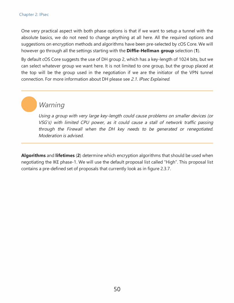
One very practical aspect with both phase options is that if we want to setup a tunnel with theabsolute basics, we do not need to change anything at all here. All the required options andsuggestions on encryption methods and algorithms have been pre-selected by cOS Core. We willhowever go through all the settings starting with the Diffie-Hellman group selection (1).
By default cOS Core suggests the use of DH group 2, which has a key-length of 1024 bits, but wecan select whatever group we want here. It is not limited to one group, but the group placed atthe top will be the group used in the negotiation if we are the initiator of the VPN tunnelconnection. For more information about DH please see 2.1. IPsec Explained.
WarningUsing a group with very large key-length could cause problems on smaller devices (orVSG’s) with limited CPU power, as it could cause a stall of network traffic passingthrough the Firewall when the DH key needs to be generated or renegotiated.Moderation is advised.
Algorithms and lifetimes (2) determine which encryption algorithms that should be used whennegotiating the IKE phase-1. We will use the default proposal list called “High”. This proposal listcontains a pre-defined set of proposals that currently look as in figure 2.3.7.
50
Chapter 2: IPsec

Figure 2.3.7 Details on the IKE & IPsec proposal list called “High”
NoteThe recommended proposal list is subject to change as there may be some newalgorithms and updated recommendations in the future.
Lifetime determines how long the negotiated IKE keys will be valid until a new set of keys needsto be created/negotiated.
Mode (3) determines which mode the Firewall should use when negotiating the VPN tunnel. Thetwo choices are Main and Aggressive mode. The default value is Main mode. More informationabout Main and Aggressive mode can be found in the 2.1. IPsec Explained . Simply put,aggressive mode is faster and can negotiate the tunnel with fewer negotiation steps/packetsbeing sent between the initiator and responder but it is also slightly less secure. Main mode isrecommended which is the value that we will use in this recipe.
51
Chapter 2: IPsec

Outgoing Routing Table (4) determines the routing table that cOS Core will use for the tunnelnegotiation and encrypted traffic. It is not traffic that is being sent inside the encrypted tunnel. Inother words, the routing table used to find the tunnel endpoint. (Can’t understand these last twosentences)
Local Endpoint (5 ) specifies if the IPsec tunnel should only accept incoming negotiationstowards a specific IP address in cOS Core. It will be used as the source IP for outgoingnegotiations. The most common use for this option is when the Firewall has more than onepublic IP address and we want the IPsec tunnel to use another IP than the default interface IPaddress for either incoming or outgoing tunnel negotiations.
Incoming Interface Filter ( 6 ), as the name implies this is a filter for incoming IPsecnegotiations. If an interface has been selected here, the IPsec tunnel will only attempt to matchan incoming negotiation that arrives on the specified interface.
Dead Peer Detection (7) is a function that monitors the status of IKE/ESP traffic on an alreadyestablished IPsec tunnel. If no IKE or ESP traffic has been observed within a reasonable time(usually around 20 seconds) it starts sending “Are you there?” queries (DPD-R-U-THERE) to thetunnel endpoint. If the tunnel endpoint is there and alive, it will respond with a DPD-R-U-THERE-ACK back, basically saying “I am here, don’t tear down the tunnel please”.
Several DPD queries are sent and if the remote endpoint does not respond to them due to onereason or the other, the IPsec tunnel will be torn down.
This function requires that the remote endpoint have support for DPD. It is rather unusual to findIPsec capable equipment today that does not support DPD.
NAT Traversal , also known as NAT-T, (8) is a way to handle situations where the client orremote endpoint is behind a device that performs NAT (Network Address Translation). Thissetting determines how the Firewall should behave when encountering NAT or if it should forcea NAT-T negotiation whenever a tunnel is negotiated. Forcing NAT-T can be very useful in somescenarios where the ISP or something in between the Firewall and remote endpoint is notallowing the required IP protocol. By forcing NAT-T we can make the Firewall use the NAT-T port(UDP 4500) instead of the IP protocol (IP Proto 50).
Auto Establish (9) is a function that attempts to keep all tunnel network combinations up at alltimes. As an example, let’s say, we have 5 networks configured as local network and 2 networksas remote networks. This means that there will be a total of 10 possible network combinations,Auto-Establish will attempt to keep all 10 established at all times.
52
Chapter 2: IPsec

This feature is quite aggressive and if a network SA is not up, it will attempt a new negotiationabout once every second. If there are more than 10 network combinations, Auto-Establishshould be avoided. We will not be using Auto-Establish in any of the recipes.
DS Field (10) is the Differentiated Service Field, it is primarily used for bandwidth prioritizationtogether with Pipes and Traffic Shaping. It can, for instance, be used to increase or decrease thepriority of the “negotiation packets” used by the IPsec tunnel. We will not cover the use of DS ortraffic shaping in this book.
The “IPsec (Phase-2)” tunnel settings tabThe second phase of the tunnel negotiation, also known as IPsec phase, has the followingoptions as shown in figure 2.3.8.
Figure 2.3.8 The IPsec tunnel’s IPsec (Phase-2) settings and options
53
Chapter 2: IPsec

Similar to IKE Phase-1, by default we do not need to change anything at all here if we want toestablish a standard/simple tunnel. We can leave all the options at default values, because thereis no input requirement in this section.
If Perfect Forwarding Secrecy (1) is used, a new Diffie-Hellman exchange is performed foreach phase 2 negotiation. While this is slower, it makes sure that no keys are dependent on anyother previously used keys. If we are the initiator, no PFS will be used as the “none” PFS group isplaced at the top of the selection list. We would however accept PFS for group 01, 02 and 05 forincoming negotiations.
NoteIt might be a good idea to change this option and remove "none" to make sure that PFSis always used in order to increase the security. In this recipe we will not changeanything but leave things at their defaults.
Algorithms (2) determine which encryption algorithms that should be used when negotiatingthe IPsec phase-2. We will use the default proposal list called “High”. This proposal list contains apre-defined set of proposals that currently look as in Figure 2.3.7.
NoteCurrently the default IKE and IPsec proposal lists called “High” are identically configured.
Lifetime in seconds (3) determines how long a newly negotiated IPsec (phase-2) tunnel shouldbe considered valid. When the lifetime expires the system will perform a re-key and the counterwill be reset. Please note that when it comes to IPsec Phase- 2, there may be multiplenegotiations done on the same tunnel based on how many networks are configured as local andremote network. We will go into more details regarding multiple networks on an IPsec tunnel inRecipe 2.6. Accessing satellite offices through central HQ using VPN.
54
Chapter 2: IPsec

Lifetime in kilobytes (4) is an optional settings where we can set an additional lifetime of theIPsec tunnel. In addition to only having a lifetime based on seconds we could also make thetunnel valid until a certain amount of data has been passing through the tunnel. The value thatreaches zero first (Time or KB) will cause a tunnel re-negotiation/re-key in Phase-2.
NoteFor the lifetime in KB, the data is calculated in both directions of the tunnel (the sum ofdata received and data sent).
Setup SA per (5 ), this option determines how the IPsec tunnel should establish the IPsecSecurity Associations (SA’s). By default we setup an SA based on network but we have the optionto use either Host or Port as well. As an example, an SA setup using the “network” option maylook like the following CLI output:
IPsec Tunnel Local Network Remote Network Remote Endpoint---------------- ---------------- ---------------- ---------------Stockholm_Tunnel 192.168.150.0/24 192.168.100.0/24 203.0.113.100
In the above CLI output we have one SA established between the network in London andStockholm. It is basically a network definition of who can communicate with whom.
Using Host (or Port) means that there will be a tunnel negotiation between London andStockholm for every host that needs to communicate. This means at worst case if we have two/24 networks it would mean 254 x 254 = 64 516 number of IPsec SA negotiations that may needto be performed. We would hit the license limit very fast in such a scenario.
Using SA per Host or Port is very unusual, the recommendation is to use SA per network unlessabsolutely necessary to do otherwise. An example of when it would be preferable to use SA perhost is if there is only communication between two hosts through the IPsec tunnel, such as thescenario of using L2TPv3 or GRE inside IPsec where communication is only performed betweentwo hosts / IP addresses.
Config Mode Pool (6) is primarily used in a Roadwarrior/roaming scenario where we want togive the connecting client an IP address once connected, which would then be used to connect toallowed resources (e.g. an internal Terminal server). We will discuss and use Config Mode Poolsin Recipe 2.4. Configuring IPsec roaming / road warrior IPsec.
55
Chapter 2: IPsec

The DS field (7) is present in phase-2 as well, the DS field in phase-1 enables us to prioritize thebandwidth of the negotiation (i.e ISAKMP) while in phase-2 it enables us to prioritize thebandwidth of the encrypted packets (i.e ESP). We will not discuss or use the DS field in this book.
The “Virtual Routing” settings tab
The Virtual Routing tab (1) is shown in figure 2.3.9 containing options related to Virtual Routingscenarios from where we want to control the traffic that traverses the tunnel in some specialway.
Figure 2.3.9 The “Virtual Routing” tab options
There may be scenarios or situations where the traffic inside the IPsec tunnel should use aspecific routing table or exit to the internet using a secondary internet connection. The VirtualRouting tab can then be used to change the routing table that the IPsec tunnel by default will useto access relevant network(s). We will not go into further details about Virtual Routing in thisbook.
56
Chapter 2: IPsec

The “Advanced” settings tab
The advanced tab contains a couple of important options that even though they are placed in theadvanced tab are quite frequently used. The advanced tab options are shown in figure 2.3.10.
Figure 2.3.10 The "Advanced" tab options
All three of our first options are related to routing. The option “Add route Dynamically” (1) isprimarily used in scenarios where the route towards the tunnel’s remote network should only beavailable once the tunnel is established. It is primarily used in roadwarrior/roaming scenarioswith IPsec clients but it is also used in some Lan2Lan tunnel scenarios. An example of a Lan2Lanscenario is where the remote endpoint is behind a dynamic IP address so we are not able toestablish the tunnel from our side. By having this option, we make sure that the route towardsthe remote network is only available once the tunnel has been successfully established.
The second option called “Add route statically” (2) means that when the IPsec interface hasbeen created and the remote network option has been configured, cOS Core will automaticallyadd a route in the <main> routing table that points to the remote network. This way we do nothave to worry about manually having to add the route once the IPsec interface has been created.
57
Chapter 2: IPsec

In this recipe we will leave the option at default which is “enabled”. A route in the main routingtable will now be created as it is shown in figure 2.3.11.
NoteThe two route options can be enabled at the same time but there is no real scenariowhere this would be useful (the behavior of this setting may be subject to change infuture versions of cOS Core).
Figure 2.3.11 The route that is created automatically if the “add route statically” option is enabled
The Route Metric (3 ) option determines the metric of the route that is either statically ordynamically created. Briefly explained, Metric is a way to tell cOS Core which route should be theprimary, secondary etc, in case there are routes for networks that are identical. The route withthe lowest metric will always be consulted first.
The default value of the IPsec metric is 90 and we will leave it at its default value.
NoteA physical Ethernet interface has default value 100. This means that if a route conflictexist, the tunnel route would be used first.
The PlainText MTU (4) setting controls the maximum payload size being sent inside the IPsectunnel before they need to be fragmented. Even though the setting says “PlainText” it isimportant to note that it is basically all packets being sent inside the encrypted tunnel. Thisincluded packets that are encrypted such as HTTPS, ZIP files and even other IPsec ESP packets incase of a scenario where we want to send IPsec packets inside another IPsec tunnel.
“Plaintext” is defined as the Original IP Packet as shown in figure 2.3.12.
58
Chapter 2: IPsec

Figure 2.3.12 What is counted/included in the Plaintext calculation
Additional Information about the Plaintext MTU
The Plaintext MTU setting assumes that the Ethernet interface MTU is set to 1500. If we use anexample with a lower value on the interface MTU e.g. 1400 it means that any encrypted ESP IPsecpackets above size 1320 bytes need to be fragmented by the IPsec engine itself. This operation ismore CPU resource demanding than fragmenting packets before they are sent to the IPsecinterface so it is recommended that the interface MTU and the Plaintext MTU setting on the IPsectunnel is correctly aligned to avoid ESP fragmentation.
If we use the default value of Plaintext MTU of 1420 it means 80 bytes up to the Ethernet MTU of1500. If we make a break down to show the composition of each of these 80 bytes, we will useAES with SHA1 encryption in this example:
l 20 bytes is for IP header
l 8 bytes for UDP header
l 24 bytes for ESP + AES
l 14 bytes for ESP trailer
l 12 bytes for ICV (SHA1)
This decomposition accounts for a total of 78 bytes. The total size varies depending on theencryption algorithms used.
The next option is the Tunnel Monitor (5), this is a feature that enables us to monitor a hostthat is part of the IPsec tunnel’s remote network using ICMP/Ping. If the target host does notrespond, cOS Core will tear down all IKE and IPsec SA’s in question present in the tunnel. TheIPsec engine will then try to reestablish the tunnel. This can be very useful to get a quick tunnel
59
Chapter 2: IPsec

re-connection in case of network/traffic problems inside the tunnel itself. Then the administratordoes not have to perform a manual delete of the tunnel but rather cOS Core can perform thisoperation itself if it detects a problem.
The last option is called IP Addresses (6). This option determines the IP address that cOS Coreshould use when traffic is either initiated from the Core itself or when we want to do someaddress translations such as NAT into the tunnel. By default cOS Core will try to use an interfaceIP address that corresponds to the chosen local network but that is not always possible.
NoteAny IP address set as IP Address (6) will become automatically core routed.
Configuring the IPsec tunnel on the Stockholm FirewallWe have now configured the London side of the IPsec tunnel. We must now configure a tunnelon the Stockholm side that matches the tunnel configured in London, as shown in figure 2.3.13.
Figure 2.3.13 The configuration of the IPsec tunnel from Stockholm to London
60
Chapter 2: IPsec

An important detail to remember is when it comes to the networks. In our initial description ofthis recipe we have chosen the following networks:
Name=StockholmNetAddress=192.168.100.0/24
Name=LondonNetAddress=192.168.150.0/24
This means that StockholmNet is the local network and LondonNet is the remote network at theStockholm side. But on the London side this is reversed, for easier understanding this isvisualized in figure 2.3.14.
Figure 2.3.14 The relation between Local and Remote network on each side
On the Stockholm site, the remote endpoint is the public IP of the Firewall in London(198.51.100.50) to which the tunnel will link in order to establish the connection but also toaccept incoming negotiations from it in case London is the initiator of the IPsec tunnel.
The last thing we need to do for the IPsec part is to create and add the same Pre-Shared key asused on the London tunnel, as shown in figure 2.3.15. As was indicated earlier, we simply use apassphrase consisting of the word “test123”.
Figure 2.3.15 The Pre-shared key used on the London Firewall
Configuring RoutingSince we used the option “Add route statically” on the IPsec interface both in London andStockholm we do not have to make any changes or add routes to the routing table. This ishandled automatically by cOS Core in this scenario.
61
Chapter 2: IPsec

Configuring IP PoliciesWe have now configured the IPsec tunnels on both sides, making sure that the routing is OK. Thelast thing we have left to do is to configure the IP policies needed to allow the traffic to but alsofrom the IPsec tunnel interface.
What we want to do is to let the network in London and Stockholm communicate with eachother without any restrictions. For this, we need a total of two rules on each side.
NoteWe will not go into details about how to configure IP policies or rules as that has beencovered in the first edition of the cookbook and also in the cOS Core administratorguide.
The two IP rules on the Stockholm sideOn the Stockholm side we create two IP Policies as shown in figure 2.3.16.
Figure 2.3.16 The two IP policies needed to communicate to/from the VPN interface
The first rule allows traffic to be initiated from the local internal network of Stockholm to theremote network in London that is routed on the IPsec tunnel. All services are selected as we wantunrestricted access between these two networks.
The second rule allows traffic to be initiated in the reverse direction, meaning that users inLondon can also initiate traffic from their side in order to reach the internal network located inStockholm.
One item that stands out on our rules is the destination interface of the second rule on bothsides. It is set to be “Any” instead of the Lan interface. The reason for this is primarily for testing
62
Chapter 2: IPsec

purposes but it may also in some operational cases this may be necessary. "Any" is used becausethere is one IP address on the internal network that is not routed on the Lan interface but ratherthe Core interface. And that is the Lan interface IP address itself.
NoteFor more information about the Core interface please see cookbook edition one and theadministrator guide for cOS Core.
By setting the rule that allows traffic from the IPsec interface to be “Any” we also allow traffic tobe sent to the IP address of the interface. This is very useful for testing purposes as we can thenuse the interface IP to test that the tunnel is working by sending a ping towards this particular IPaddress in either direction.
The two IP rules on London sideOn the London side we create two rules as shown in figure 2.3.17.
Figure 2.3.17 The two IP policies needed to communicate to/from the VPN interface
In London we create similar rules, allow traffic to be initiated from London’s internal networktowards the network in Stockholm and also vice versa.
63
Chapter 2: IPsec

Verifying that the VPN tunnel is working using the CLIOnce all the IPsec tunnels, routing and IP policies are configured it is time to test to see whetherthe tunnel is working. The easiest way to test this is to connect to cOS Core CLI and then ping ahost routed beyond the IPsec tunnel. If we use the Stockholm firewall as our first unit to testfrom we initiate the following CLI command:Stockholm:/> ping 192.168.150.1 -verbose
Sending 1 4-byte ICMP ping to 192.168.150.1 from 192.168.100.1... using route "192.168.150.0/24 via London_Tunnel, no gw" in PBR table "main"ICMP Reply from 192.168.150.1 seq=0 time=<10 ms TTL=255
Ping Results: Sent: 1, Received:1, Avg RTT: 10.0 ms
The ping issued in this instance is the interface IP address on the London firewall(192.168.100.1). cOS Core will perform a route lookup to try to locate where this IP address isand has determined that it should be sent to the “London_Tunnel” interface. Since we allowedthis communication by setting “Any” as the destination interface in our IP Policy (see figure2.1.16) we have a very useful IP to use for the initial testing. This, of course. can be any host onthe London network that responds to ping but that may not always be the case.
NoteThe first packet sent into the tunnel will trigger the tunnel initiation sequence, thismeans that the first packet (depending on timing) will in most cases have higher latencythan subsequent packets.
64
Chapter 2: IPsec

We can also perform a similar ping test from the London firewall to Stockholm to verify thattraffic can be initiated in both directions:London:/> ping 192.168.100.1 -verbose
Sending 1 4-byte ICMP ping to 192.168.100.1 from 192.168.150.1... using route "192.168.100.0/24 via Stockholm_Tunnel, no gw" in PBR table "main"ICMP Reply from 192.168.100.1 seq=0 time=<10 ms TTL=255
Ping Results: Sent: 1, Received:1, Avg RTT: 10.0 ms
NoteIn order to test the initiating sequence, e.g. making sure the tunnel can initiate fromboth sides, the tunnel has to be torn down before it can be properly initiated from aspecific side.
A similar test can of course also be performed in the WebUI under Status->Tools->Ping, but theCLI provides a greater level of detail that can be very useful if we need to perform anytroubleshooting. A similar ping done from the WebUI on the London firewall is shown in figure2.3.18.
Figure 2.3.18 Performing a ping test using the ping tool in the WebUI
65
Chapter 2: IPsec

To check the status of the IPsec tunnel itself we can use either the WebUI under Status->IPsec oruse the CLI command “IKE” to see the status of the phase-1 IKE SA or “IPsec” to see the status ofthe phase-2 IPsec SA’s (if more than one network). Below is the output displayed from Londonwhen using the IKE and IPsec commands when the tunnel has been established:London:/> ike
--- Active IKE SAs:
Interface Local Endpoint Remote Endpoint Local ID Remote ID--------- --------------- --------------- ---------------- ----------------Wan 198.51.100.50 203.0.113.100 198.51.100.50 203.0.113.100
1 of 1 active SAs displayed
London:/> ipsec
--- Active IPsec SAs:
IPsec Tunnel Local Network Remote Network Remote Endpoint------------------ ------------------ ------------------ ------------------Stockholm_Tunnel 192.168.150.0/24 192.168.100.0/24 203.0.113.100
1 of 1 active SAs displayed
Changing the tunnel from IKE version 1 to IKE version 2When it comes to selecting which IKE version to use, it is to the decision of the administrator. Weare moving more and more towards IKEv2 and it will not be long until IKEv2 is selected bydefault when creating new IPsec tunnels.
Configuration of IKEv2 based IPsec tunnels is almost identical to the method used for IKEv1 withsome subtle differences such as:
l Authentication using XAuth is only possible with IKEv1. Authentication with IKEv2 must useEAP.
l The AES-XCBC authentication algorithm is only supported by IKEv2. If AES-XCBC is used ina proposal list with IKEv1, it will be skipped. If AES-XCBC is the only algorithm in theproposal list with IKEv1, the tunnel setup will fail.
l The Encapsulation Mode property of an IKEv2 tunnel can only be “Tunnel”. This means thatIKEv2 cannot be used together with L2TP. The intended replacement for L2TP is to use apure IKEv2 roaming VPN tunnel together with Certificates and EAP authentication.
66
Chapter 2: IPsec

In our example scenario we currently have a fully working Lan2Lan tunnel using IKEv1 betweenStockholm and London. If we want to modify this tunnel to use IKEv2 we must do the following:
1. Open the IPsec tunnel on London & Stockholm.
2. Locate the option to change IKE version, as shown in figure 2.3.19.
Figure 2.3.19 Changing the IKE version on the IPsec tunnel in the Stockholm Firewall
3. Then change the IKE version from IKEv1 to IKEv2.3.1. Please note that the Encapsulation Mode presents as grayed out, this is because onlytunnel mode is supported in IKEv2.
And that’s it! We do not need to do any other changes. In this scenario, the proposal lists,network configuration etc. are all the same and can be used for IKEv2 as well.
Whenever possible, IKEv2 should be used.
Requirements checkAs a last step in our first recipe we will do a quick check for whether we can meet therequirements we defined at the start of the recipe. If we break them down one by one:
l Users in London should have unrestricted access to Stockholm’s local network through theencrypted IPsec tunnel.
o In this recipe, the routing is automatically handled and setup by cOS Core. As long aswe make sure to define and use the correct network on the IPsec tunnel’s RemoteNetwork setting the routing should be adequate.
Secondly we create two IP policy rules that allows traffic to/from the IPsec tunnel (seefigure 2.3.16) without any restrictions when it comes to ports or protocols.
Status: Fulfilled.
67
Chapter 2: IPsec

l Users in Stockholm should have unrestricted access to London’s local network through theencrypted IPsec tunnel.
o Similar to the previous requirement the routing is handled automatically and the IPpolices allow the communication to/from the IPsec tunnel. London can talk toStockholm and vice versa without any port restrictions.
Status: Fulfilled.
l Access should be allowed to only one network through the IPsec tunnel from each side.
o As we have only defined one network for use on both the Local and Remotenetworks on each IPsec tunnel for both London and Stockholm, it will not be possibleto access any other network. To further lock down this requirement we have in our IPpolices defined specifically which network should be allowed access to/from theIPsec tunnel interface on both the London and Stockholm Firewalls as shown infigures 2.3.16 and 2.3.17.
Status: Fulfilled.
68
Chapter 2: IPsec

Recipe 2.4. Configuring IPsec roaming / road warriorIPsec
ObjectivesIn this recipe we will configure cOS Core to accept incoming connections / negotiations fromIPsec VPN clients. The definition of roaming or road-warrior varies depending on vendor but thebasic principle is that one or more clients connect to the IPsec server (in our case cOS Core) fromlocations all across the country (or globe). Compared to a Lan2Lan tunnel, the administrator willnot know from which specific endpoint IPs the clients are making the connection, which meanswe have to approach this problem differently. A client that can connect from a random (dynamic)or unknown IP is commonly known as Roaming or road warrior client. We will be using the term“Roaming” in this book.
The scenario is as shown in figure 2.4.1. The objective of this recipe is to configure cOS Core asthe Roaming "server" to which clients around the world connect in order to access protectedresources located behind the LAN interface of the Firewall.
Figure 2.4.1 A common IPsec roaming scenario with clients around the globe
69
Chapter 2: IPsec

Detailed DiscussionBefore we start to configure the new IPsec tunnel we will have a look at our current networksetup on the Firewall we will use as the Roaming server. We have the following external IPaddress and internal network:
1. Name=Stockholm_EndpointAddress=203.0.113.100
2. Name=Lan_NetAddress=192.168.100.0/24
RequirementsBefore we start configuring the new tunnel we must look at what kind of requirements we mayhave. Since we want to keep things simple we only have two requirements in this scenario:
l Connected clients should be able to access the entire internal network (Lan_Net).
l Connected clients should be able to access the Internet through the tunnel.
In order to satisfy the second requirement, the administrator may consider applying networkpolicies such as Anti-Virus, Application Control and more for connected clients. By letting clientsuse the VPN tunnel to surf/connect to the Internet we can increase the overall security of e.g. asales representative that travels all around the world and may risk getting exposed to insecureInternet connections. By configuring the clients to access the internet through the VPN tunnel weadd another layer of security apart from having Firewall and Anti-Virus software installed locallyon the client devices.
70
Chapter 2: IPsec

Creating the roaming IPsec interface, general tabThe first thing we need to do is to create the IPsec interface itself. This is done under Network->Interfaces->IPsec->Add . Once the IPsec interface is created, we will proceed withconfiguring the new Roaming tunnel interface as shown in figure 2.4.2.
NoteWe will not go into details about what each setting does, for more information abouteach setting in the IPsec interface section please see Recipe 2.3. A basic IPsec Lan to Lantunnel scenario.
Figure 2.4.2 Creating the IPsec roaming interface
For our Roaming tunnel, we will use the following settings. First the IKE Version (1) we will selectIKEv1. But if the client has support for IKEv2 and it contains all the feature sets we require, it isrecommended to use IKEv2. For now we will use IKEv1 as it is still the most common version touse for IPsec tunnels. In respect to configuration the difference between IKEv1 and IKEv2 is made
71
Chapter 2: IPsec

in this scenario only by the selection chosen in this box, so it can easily be switched to use IKEv2in the future assuming of course that the VPN clients support it.
The Encapsulation mode (2) will use the tunnel model. No change from the default setting. Formore information about tunnel and transport mode please see the 2.2. IPsec Tunnel Propertiessection.
Local Network (3) will be configured to be all-nets. The reason why we want to use all-nets isbecause of the second requirement we had earlier. We want clients to be able to surf the internetthrough the tunnel. As we do not know which IP address the client would like to access on theinternet, we must allow the client to request any IP through the tunnel.
We must remember that the Local Network on the Roaming server is the Remote Network forthe client. From the client’s perspective, it needs to be able to access every IP and network, and itwill be configured to use the IPsec tunnel to achieve that. See figure 2.3.14 in the Basic IPsecTunnel recipe for an example of the correlation between Local and Remote network.
Remote network (4) is where we configure the network from which the client will connect anduse as source network. In this case we have chosen the object called “CFG_Pool”. This is a specialobject that is used by the Config Mode pool. We will discuss the usage of Config Mode furtherdown in this recipe. Basically we restrict the clients to only be able to use an IP/network assource that is part of the Config Mode pool. By doing this we minimize the risk of a client using asource IP or network that conflict with a server or host on our internal network when connected.This should not happen when using CFG Mode as we tell the connecting client what IP it shoulduse but it never hurts to add a second layer of IP/network verifications.
The Remote Endpoint (5) will be left at the default value, which in this case is <none>. Thismeans that we do not specify any network(s) for use as the remote endpoint for the tunnel. Thiswould be the same as if we had chosen “all-nets”, which means all IP addresses. We must do thisas we do not know from which IP our client(s) will connect from and is also the reason why it isreferred to as a roaming IPsec tunnel. The client may “roam” around the world and connect froma large number of different IP addresses. An example would be a traveling sales representativewho connects to his work network from various hotels around the world.
Sidenote: It is possible to combine Geolocation with this to only allow access to the IPsec serverfrom specific countries. But this is a scenario that will not be discussed in this book as it requiresthe advanced setting “IPsecBeforeRules” to be disabled.
72
Chapter 2: IPsec

Creating the roaming IPsec interface, authenticationThe next step in the configuration is to configure an authentication source. To keep things simplewe will be using a pre-shared key together with XAuth username/password. First we create andset a pre-shared key on the IPsec tunnel as shown in figure 2.4.3.
Figure 2.4.3 Adding a pre-shared key to the roaming tunnel
This Pre-shared key must be provided to all clients that want to connect to our roaming “server”.It is, however, recommended not to send the pre-shared key in a normal mail but use an SMSservice or similar. For example, send the connection information (IP of the server etc) via e-mailbut the PSK in an SMS.
The second feature we want to activate on the Authentication tab is XAuth as shown in figure2.4.4.
Figure 2.4.4 Enabling XAuth on the IPsec tunnel
XAuth is an extension to the normal IKE exchange and is a way to require that connecting usersinput a valid username/password in order to establish the VPN connection. Since we want toknow who connects to our Roaming IPsec server we enable this option. We will explain on howto link this particular feature to a specific user database later in this recipe.
Creating the roaming IPsec interface, phase-1For the phase-1 settings we do not change anything from default, we leave every setting as is.For a figure of how the default setting is configured please see figure 2.3.6 in previous recipe.
73
Chapter 2: IPsec

Creating the roaming IPsec interface, phase-2For phase-2 we do not change any of the settings except for the Protected Networks Settings.Here we need to specify a Config Mode Pool as shown in figure 2.4.5.
Figure 2.4.5 Selecting a Config Mode Pool to use for our roaming tunnel
Config Mode is similar to a DHCP server for VPN clients. It is a method of assigning IP, Netmask,DNS and more to connecting clients as shown in figure 2.4.6. We will now go through thevarious Config Mode Pool settings.
Figure 2.4.6 Config mode options
The first option (1) is to select whenever we want to use a static IP pool or a pre-defined IP poolobject. A pre-defined IP Pool object is a dynamic object which consists of IP leases that are pre-fetched from a DHCP Server.
74
Chapter 2: IPsec

In order to keep things simple we use the default “Static IP pool" type. For this type we mustdefine an IP pool to use. In our address book we create an IP4 address object called “CFG_Pool”with the following value:
192.168.240.1-192.168.240.100
We then use this newly created object as our “IP Pool” (2) in our Config Mode Pool.
The Netmask (3) determines the size of the network. In our scenario the size of the internalnetwork is /24 so then the netmask will be 255.255.255.0.
DNS (4) address is the address of the DNS server we want the connected IPsec client to use. Wewill use our external DNS server that we received from our ISP, but it might as well be an internalDNS server, it will be up to the administrator depending on the scenario.
There are also some less frequently used options that exist in the Config Mode Pool options,these options are the following.
The NBNS/WINS (5) option enables us to set an IP of the Windows Internet Name Service (WINS)servers that will be handed out to connecting clients. It can be used in Microsoft environmentswhich uses NetBIOS Name Servers (NBNS) to resolve IP addresses to NetBIOS names.
DHCP (6) enables us to specify the IP address of a DHCP server in case the connecting clientsends any DHCP requests. These requests will be forwarded to the specified IP address.
The Subnets (7) option enables us to send additional networks to the client. This will be neededin more advanced split tunneling scenarios where the connecting client needs access to morethan one network. This option will be discussed and used further in Recipe 2.5. Configuring IPsecroaming split tunneling with multiple networks..
The Prefixes (8) option is the IPv6 equivalent of the previous Subnets (7) option. If we want tosend additional IPv6 network(s) to the client this is the option to use. Since we are not using IPv6in this scenario we will leave it blank.
75
Chapter 2: IPsec

Creating the roaming IPsec interface, AdvancedWe will not change anything from default in the Virtual Routing tab so we move on to theAdvanced tab as shown in figure 2.4.7.
Figure 2.4.7 The advanced settings on the roaming IPsec tunnel
There are two options in the advanced tab that we need to change from the default. The firstoption is the “Add route Dynamically” that we want to enable, the second is the “Add routeStatically” that we want to disable.
As we are connecting with a roaming client that can arrive from any source IP we are usingConfig Mode Pool to hand out an IP address to the client. In order to keep the various clientsseparated we want cOS Core to keep track of which IP belongs to what IPsec tunnel session, andthe first option (1) does just that. cOS Core achieves this by dynamically adding a route to theclient for the IP it receives from the Config Mode Pool. Then cOS Core will know which IPbelongs to what IP tunnel session. This route only exists as long as the client is connected, whenthe client disconnects the route disappears.
This is also the reason why we need to disable the second option as such a route would first ofall be for the entire Config Mode Pool range and it exists statically, meaning that it still persistsafter the client(s) has disconnected from the server.
Once a client is connected the dynamic route will be shown in the CLI output of the routing tablelike this:Flags Network Iface Gateway Local IP Metric------ ----------------- -------------- -------------- --------------- ------D 192.168.240.1 Roaming_IPsec 0
The flag “D” means “Dynamically added”. In this case it is a route added automatically by theIPsec engine once the client has successfully connected. The network is the IP address theconnecting client received from the Config Mode Pool.
76
Chapter 2: IPsec

This concludes the IPsec part of the setup, we will now continue with the username/passwordpart of the negotiation.
Adding username and password requirementWe have so far configured the IPsec tunnel but we want to add another layer of security byforcing our users to input a username and password in order to establish the tunnel.
Creating and adding users to the Local User Database.The first step is to create a new Local User Database. To accomplish this, we go to System->Device->Local User Databases and create a new database as shown in figure 2.4.8.
Figure 2.4.8 Creating/adding the Local User Database
Once the database is created, we call the database “Roaming_Users” we can start adding users tothe database. The General tab contains the name of the database and a comment field while thesecond tab, as shown in figure 2.4.9, contains the ability to add/remove and edit users in thedatabase.
Figure 2.4.9 The user summary in the Local User database
77
Chapter 2: IPsec

There are additional options available on each user but to keep things simple we will not discussor use them in this recipe, we simply create a few users and set their passwords.
User Authentication, creating the ruleOnce the database has been created we now want to create the user authentication rule.Previously we activated XAuth on our IPsec tunnel but we now must link this function to a userauthentication rule. To do that we go to (in the WebUI) Policies- >User Authentication->Authentication Rules and create a new User Authentication rule as shown in figure 2.4.11.
Figure 2.4.10 Creating the User Authentication Rule
User Authentication, general options tabOnce the rule is created we are greeted but several tabs of options as shown in figure 2.4.12.
Figure 2.4.11 The General options on the User Authentication rule
We will go through all the tabs (some briefly) in order to give details on how we can connect ourIPsec tunnel XAuth function to a User Authentication rule.
78
Chapter 2: IPsec

We start with selecting the Authentication Agent (1). This determines what type of authenticationwe want our Authentication rule to trigger on. Since we have activated XAuth on our IPsec tunnelwe select the XAuth authentication agent.
There are of course other Authentication Agents such as HTTP, HTTPS, EAP etc. but they will notbe used in this recipe.
NoteThe XAuth agent is a slight exception to other User Authentication rules, because eventhough we can create multiple XAuth agent rules, only the one at the top will trigger.This means that we cannot user different authentication databases based on an IPsecinterface. The selected database on the first XAuth rule will be used for all IPsecinterfaces that use XAuth.
The Authentication source (2) determines what kind of authentication database we want to usefor our users. We have multiple choices such as Local, LDAP, Radius etc. To keep things simplewe will use a Local database which means that the database containing the username andpasswords for our users will be located in cOS Core’s configuration. This solution is viable forabout 20-40 users but any more users than that and it is recommended to use a system that isbetter suited for large scale user database handling such as Radius or LDAP.
The interface (3) is a way to use different user databases, and is based on the interface on whichthe user authentication request will be received. Due to the limitations using XAuth, mentionedin the previous note, this option is grayed out and it will not be possible to choose anything herewhen using XAuth as the agent.
Originator IP (4) determines which IP addresses/network that will be allowed to connect andauthenticate towards the roaming IPsec tunnel. This means that only clients that belong to theOriginator IP/Network will be allowed to authenticate using XAuth. Since this is a roaming tunnelwe do not know from which IP the clients are connecting from, we will leave this setting on itsdefault value which is All-nets. We allow anyone that can get past the phase-1 negotiation of theIPsec tunnel to perform a login attempt.
Terminator IP (5), this setting can (depending on Authentication Agent (field 1)) limit incomingauthentication attempts to only be triggered if the client connects to a specific IP address
79
Chapter 2: IPsec

(endpoint). As we are using IPsec and the XAuth agent this part is handled by the IPsec tunnelinterface and the reason why the option is grayed out.
User Authentication, log settings tabThe Log Settings tab contains an option that activates cOS Core to generate log events if a userperforms a failed authentication attempt or is logged in/out. It is strongly recommended to leavethis option at the default value, which is enabled.
User Authentication, authentication options tabThe Authentication Options tab contains options related the Authentication Source we selectedearlier (see Figure 2.4.11) and is shown in figure 2.4.13.
Once the rule is created we are greeted but several tabs of options as shown in figure 2.4.12.
Figure 2.4.12 The Authentication Options on the User Authentication rule
Since we have not selected either Radius (1) or LDAP (2) as our authentication agent thesechoices are grayed out. We do, however, have to select which Local User Database (3) to use.
80
Chapter 2: IPsec

A local User Database means that the user database is stored in the cOS Core configuration filedirectly without the need to contact any external server as with Radius or LDAP.
By default there exists one pre-defined local database called “AdminUsers”. This database is thedatabase used when connecting to cOS Core using SSH or the WebUI. We can use this databaseif we so choose, but it would be much better to create a new local database that is specificallyused for our roaming clients (also we do not want our VPN users to be able to login to theWebUI of the Firewall).
User Authentication, accounting options tabThe accountings tab is used if we want to use Radius accounting. Radius accounting is, simplyput, a way to track how much data a user has sent/received. It can be useful for scenariosinvolving data transfer limits where a user is only allowed to send/receive certain amount ofdata before the need to buy more.
We will not use Radius accounting in this scenario so we will not go into any detail about thevarious options under the Accounting tab.
User Authentication, restrictions option tabThe Restrictions tab contains options related to user restrictions such as idle timeouts as shownin figure 2.4.10.
Figure 2.4.13 The Restriction options on the User Auth rule
81
Chapter 2: IPsec

The first option is Idle Timeout (1), this setting controls how long a client can be left idle (withoutgenerating and traffic) before he/she is automatically disconnected from cOS Core. We leave it atthe default 1800 seconds (30 minutes) value.
Session Timeout (2) controls how long the client is allowed to stay connected no matter if he/sheis idle or not. This means that even if the client is being active, he/she will get disconnected oncethe configured session timeout reaches zero. We will not use any session timeout in thisscenario. It is quite unusual to use this particular option but it can be useful if there is a largeamount of users connected on a daily basis to the server and to avoid that partially idle users areclogging up the system needlessly.
The “User timeouts received…” (3) option is an option only available when Radius or LDAP isused and a timeout value is sent in the reply from the authentication server. As we are usingLocal Database this option is grayed out and will not be used.
Lastly we have various options that let us control how to handle Multiple Username Logins (4). Itwill be up to the administrator to decide which option that would be applicable to thesituation/scenario. For this recipe we will use the default “Allow multiple logins” which meansthat the same user can login multiple times using the same account. It can be advantageous incase the user is on a shaky connection and risk getting disconnected on and off, then instead ofhaving to wait until the previous user session expires he/she can simply login and create anothersession. The drawback would be if the username/password is compromised it can be used tologin multiple times from the same account, significantly increasing illegal access to thecompromised network.
Creating the IP policies needed for network accessBefore we create the IP policies that determine what kind of access our connected VPN clientsshould have, let’s again review the two requirements we had for access mentioned initially inthis recipe:
Requirement-1: Connected clients should be able to access the entire internal network (Lan_Net).
Requirement-2: Connected clients should be able to access the Internet through the tunnel.
Up until now we have configured the IPsec roaming tunnel and the needed pool, and the UserAuthentication rule. Clients can now connect to cOS Core but they are still unable to access anyresources. To do that we need to configure some IP policies based on our requirements.
82
Chapter 2: IPsec

First we create the rule that give our client access to the internal network (Lan_Net) as shown infigure 2.4.14.
Figure 2.4.14 The first IP Policy that provides connected VPN clients with access to the internal Lannetwork
Please note that the there is no address translation used. There is no need to mask the IP addressfrom which the clients are connecting when accessing the internal network. NAT should beavoided whenever possible for logging purposes as we can more easily track potential problemsor even attackers.
NoteThe reason why we set Destination Interface to “Any” is because we would like to beable to send ping/ICMP packets to the Lan interface IP itself for testing purposes (or formanagement). Since this IP is routed on Core it will not trigger if we select “Lan” as thedestination interface. If there is no such need, we can set destination interface to be theLan interface instead.
The second rule is to fulfill the second requirement of providing connected clients with access tothe Internet using the VPN tunnel as shown in figure 2.4.15.
Figure 2.4.15 The second IP Policy that provides connected VPN clients with access to the Internetthrough the VPN tunnel
Since we are allowing clients to reach the Internet, we must NAT the traffic from the connectedVPN clients. This means that when these clients connect to the Internet their source IP will be thepublic IP of the Firewall and not their PC at home. This is the same principle that many
83
Chapter 2: IPsec

anonymizer service providers are using to protect or hide users by connecting to a VPN serverthat then mask their source IP using NAT.
And that concludes this recipe on how to configure cOS Core to act as a server for incomingroaming VPN clients.
Questions & Answers:Question:Why is the CFG mode pool not part of the local network in this scenario?
Answer: The reason for this is because the IPsec tunnel interface does not have ARP orProxyARP support. Meaning that if we give out IP address in the internal network, internal hostswould send an ARP query to try locate the host they believe belongs to their own networksegment, and if cOS Core does not reply to those queries, the communication will fail. Byhanding out IP addresses in a completely different subnet IP range the internal clients will simplyask their default gateway, which in this scenario will be cOS Core and then the communicationwill work without any problems.
Question: But I want my connected clients to be in the same subnet, is there no alternativesolution?
Answer: There is an alternative solution. We can use a behavior in cOS Core where it willrespond to ARP queries even on the route the ProxyARP is not configured on. This is briefly howit can be configured.
1. Change the CFG mode pool to be part of the local network, e.g. 192.168.1.200-192.168.1.220
2. Create a route in the routing table that looks like this:
Route Roaming_IPsec CFG_Pool ProxyARP=Lan
When clients now connect, cOS Core will setup a single-host route for the IP the client receivesfrom the IP pool but since the ProxyARP and the routes are using separate sub-processes theyare looked at separately. So even though the ProxyARP route does not primarily match (as it isbigger than the single-host route), it will still respond to the ARP query and the scenarioworkaround would work.
84
Chapter 2: IPsec

Question:Why is “all_services” used on the IP policies. Is that wise?
Answer: This is primary for testing purposes that all_ services is used as it includes all IPprotocols, including TCP, UDP and ICMP. When configuring this for a live productionenvironment it is recommended to either use a service group or create multiple IP policies onlyfor the specific services/ports that we want to allow such as DNS, HTTP, HTTPS, FTP etc.
It is also a good opportunity to apply additional security functions on the traffic towards theInternet such as Anti-Virus, Web Content Filtering, Intrusion Detection etc. to protect clients thatare traveling around the world from malicious content. Not to mention to increase security andprotection of the servers that is being accessed through the VPN tunnel.
85
Chapter 2: IPsec

Recipe 2.5. Configuring IPsec roaming split tunneling withmultiple networks.
ObjectiveThe objective of this recipe is to use the previous recipe as base but with slightly differentrequirements. In this recipe, we want our roaming users to be able to reach three internalnetworks instead of just one, also we will not allow internet access through the VPN connection.
The scenario is depicted in figure 2.5.1.
Figure 2.5.1 A roaming VPN scenario with clients around the globe that wants access to multipleinternal networks
86
Chapter 2: IPsec

Detailed discussion
RequirementsWe have the following requirements for this scenario:
l Requirement: Connected clients should be able to reach all the internal networks asshown in figure 2.5.1.
l Requirement: Connected clients should not be able to reach the internet through theVPN connection. They should use their normal ISP connection when surfing the internet.
Initial setupThis recipe will be using the previous recipe as base and assumes the roaming VPN connectionis already configured with the previous recipe parameters.
We will use the following objects that we have created in the address book:
1. Name=Lan_NetAddress=192.168.100.0/24
2. Name=DMZ_NetAddress=192.168.110.0/24
3. Name=Admin_NetAddress=192.168.120.0/24
87
Chapter 2: IPsec

Modifying the IPsec tunnelIn our previous recipe we used the network configuration as shown in figure 2.5.2 on our IPsectunnel.
Figure 2.5.2 The current network configuration on the roaming IPsec tunnel
The local network was set to be “all-nets”, just as our previous requirement demanded, so thatthey should be able to surf to the internet. Since we no longer allow “all-nets” due to the newrequirement, the Local Network definition needs to change to reflect only the specific networksto which the roaming VPN users should be granted access.
To accomplish this we create an address book group with the 3 local networks as shown infigure 2.5.3. We call this group “Local_Net_Group”.
Figure 2.5.3 The network group consisting of the 3 internal networks as members
88
Chapter 2: IPsec

Once the group is created we change the Local Network on our IPsec tunnel to use the groupobject instead of all-nets as shown in figure 2.5.4.
Figure 2.5.4 Using the newly created group object as the Local Network on the IPsec tunnel
Modifying the Config Mode poolWe have so far modified the IPsec tunnel to restrict the VPN clients to gain access to only 3specific networks. But we also must inform the connecting VPN clients of this, otherwise the VPNclients will attempt to surf the Internet through the tunnel and that is something we do not allownor want them to do. If the client attempts to connect, the connection attempt will fail as well ascOS Core will not allow the client to use a larger network than that configured.
To accomplish this we modify the Config Mode pool object we created in the previous recipe tolook as in figure 2.5.5.
Figure 2.5.5 Add the newly created group as Subnets on the Config Mode Pool object
By adding the newly created group object as the Subnets (2) we will inform any client thatconnects, what kind of network(s) that can be found beyond the IPsec tunnel.
89
Chapter 2: IPsec

ImportantThis depends heavily on the feature set of the IPsec client whether it supports usingmultiple subnets or not. An alternative if it does this is not required, would be toconfigure a bigger local network on the IPsec tunnel such as 192.168.0.0/16 or192.168.100.0/19 that contains all 3 networks, assuming of course it does not cause anyconflicts with an existing network.
In this scenario, the DNS parameter (1) is optional, it may or may not be needed. It will be up tothe administrator to decide whether a DNS server should be provided to the client or not. Wecannot use our previously defined DNS server, as the IP address to that DNS server requiresaccess to a network we no longer allow (true Internet access basically).
It might be useful to provide the IP to an internal DNS server for easier access to locally namedresources, but it is optional.
Modifying the IP policy rule(s).The last thing we need to do is to modify our IP Policies to incorporate the new requirements. Aswe do not want our users to surf to the Internet through the IPsec tunnel we remove the IPpolicy rule that allows Internet access. This rule would not be possible to trigger in any event,because the IPsec engine would not allow it
The only IP policy we need is a rule that allows access from the IPsec interface to the internalnetworks as shown in figure 2.5.6.
Figure 2.5.6 The IP policy needed for access to the internal network group from the IPsec tunnelinterface
We set the destination interface as “Any ” as the networks we want to reach are all behinddifferent interfaces. We also set the destination network to be the network group we createdearlier in order to give our clients access to all three networks.
90
Chapter 2: IPsec

Additionally, there are some alternatives on how this can be configured.
1. Use “Any” as destination interface then use the Network group as destination network(above example.
2. Create an interface group of Lan, DMZ and Admin interfaces and use the interface group asdestination interface and the network group as destination network.
3. Create three different IP policies, one for each destination interface and network.
Which method to use, is to the decision of the administrator. All three methods have theiradvantages/disadvantages.
Requirement checkThis concludes this recipe. As a last step we will look through the initial requirements to see ifthey can now be met. We will go through them one by one.
l Connected clients should be able to reach all the internal networks as shown in figure2.5.1.
o We modified our IP Policies, Config Mode Pool and IPsec interface configuration toallow connections from the clients towards all the desired internal networks.
Status: Fulfilled.
l Connected clients should not be able to reach the internet through the VPN connection.They should use their normal ISP connection when surfing the internet.
o We limited the amount of networks that should be reachable through the tunnel bymodifying the subnets on the Config Mode Pool and the local networks on the IPsectunnel interface. This means that the clients will have to use their normalISP connection for any traffic that is not directed towards one of the specific networkswe have defined.
Status: Fulfilled.
91
Chapter 2: IPsec

Questions & Answers:Question: What about the Config Mode pool, it currently contains only IP addresses from thefirst network?
Answer: This is unfortunately unavoidable, the IP pool object used on the Config Mode pool canbe set to be a range of multiple networks but the IPsec engine would hand out the IP addressone by one in sequence and not depending on the network the user is attempting to access. Theeasiest solution is to configure the IP pool to be in a range that is not a part of any of thedestination networks. Then we also avoid any potential problems with ARP (as mentioned in theprecious recipe).
92
Chapter 2: IPsec

Recipe 2.6. Accessing satellite offices through central HQusing VPN
ObjectiveA very common Lan2Lan tunnel scenario is when a company has a central HQ together with acouple of satellite offices. The satellite offices should not only be able to communicate with theHQ network but should be able to connect and communicate with the other satellite officesnetworks.
The objective of this recipe is to configure IPsec tunnels from satellite offices to a central HQ siteas shown in figure 2.6.1, with the added option that the satellite offices should be ablecommunicate with each other as well using the tunnel towards HQ.
Figure 2.6.1 A Lan2Lan tunnel scenario where the satellite offices access each other using the IPsectunnel to HQ
93
Chapter 2: IPsec

This means that there will be no Lan2Lan tunnel connected directly between the satellite offices.We will use the tunnel towards HQ for that. So, if for instance the London office wants tocommunicate with the Berlin office, the traffic would first to go from London to HQ and thenfrom HQ to Berlin. Intentionally we use HQ as a stopping point to reach the target office asshown in figure 2.6.2.
Figure 2.6.2 An example of the traffic flow when a connection is initiated from London to Berlin
Detailed discussion
RequirementsFirst we have a look at what kind of requirements we would like to implement, for this scenariowe have the following requirements:
l HQ should be able to reach both the Berlin and London networks
l Berlin should be able to reach both London and HQ networks
l London should be able to reach both Berlin and HQ networks
l Public Internet access from each satellite office should not go through the VPN tunnel.
For this recipe, we assume that you are already familiar with setting up a standard Lan to Lantunnel (if not please see Recipe 2.3. A basic IPsec Lan to Lan tunnel scenario). We will not go intospecific IPsec tunnel settings but rather go almost immediately into the tunnel networkconfiguration.
This type of scenario can quickly become complex, having a small network schematic (sketch)available before starting to configure is recommended in order to avoid a potential network mix-up.
94
Chapter 2: IPsec

Initial setupOn each Firewall we have the following objects created:
Stockholm-Net Address=192.168.100.0/24Stockholm-IP Address=203.0.113.100London-Net Address=192.168.150.0/24London-IP Address=198.51.100.150Berlin-Net Address=192.168.200.0/24Berlin-IP Address=192.0.2.200
NoteThe single-IP addresses are just documentation examples.
We will be using Pre-shared keys as authentication for the Lan2Lan IPsec tunnels.
IPsec tunnel configuration, LondonFor the IPsec tunnel in London we want it to be able to access the networks in Stockholm andBerlin. The difficult part here is that the London Firewall will not be aware that the Berlin networkis not actually behind the Stockholm-HQ Firewall. Instead, the London firewall will believe thatthe Berlin network is behind Stockholm-HQ.
London Local Network:
London-Net 192.168.150.0/24
The networks that London wants to be able to reach beyond the IPsec tunnel to Stockholm-HQ:
Stockholm-Net 192.168.100.0/24Berlin-Net 192.168.200.0/24
95
Chapter 2: IPsec

To illustrate this further in figure 2.6.3, we show how the London firewall will view the networkconfiguration.
Figure 2.6.3 The tunnel network configuration from the London firewall’s perspective
The tunnel network configuration from the London firewall’s perspective.
Since we want to reach two networks beyond the IPsec tunnel we create a network groupconsisting of Stockholm-Net and Berlin-Net, we call this group LondonHQ-Net as shown infigure 2.6.4.
Figure 2.6.4 The network group for the network beyond the IPsec tunnel used on the LondonFirewall
Naming the objects can easily get confusing here, if we call the group object “HQ-Net” only andthen use the same name for the network group object on the Berlin Firewall or at Stockholm-HQ,it can cause mistakes as they have the same name but contain different networks.
By calling the object “LondonHQ-Net” we give a hint that this object is for use on the LondonFirewall and contains the remote networks located behind the tunnel towards HQ. It will,however, be up to the administrators to name the object in a way they feel is working for theirenvironment and network structure.
96
Chapter 2: IPsec

On our London to Stockholm-HQ IPsec tunnel, we use our newly created network group as theRemote Network on the IPsec tunnel as shown in figure 2.6.5.
Figure 2.6.5 Using the network group on the IPsec tunnel from London to Stockholm-HQ
IPsec tunnel configuration, BerlinFor the IPsec tunnel in Berlin we want it to use a similar setup as in London. The difference inBerlin is that we want to access the networks in Stockholm and London. The Berlin Firewall willnot be aware that the London network is not behind the Stockholm-HQ Firewall. Instead, it willbelieve that the London network is behind Stockholm-HQ.
Berlin Local Network:
Berlin-Net 192.168.200.0/24
The networks that Berlin want to be able to reach beyond the IPsec tunnel to Stockholm-HQ:
Stockholm-Net 192.168.100.0/24London-Net 192.168.150.0/24
97
Chapter 2: IPsec

Similar to the London firewall we illustrate this further, in figure 2.6.6, by showing how the Berlinfirewall will view the network configuration.
Figure 2.6.6 The tunnel network configuration from the Berlin firewall’s perspective
As we want to reach two networks beyond the IPsec tunnel we create a network groupconsisting of Stockholm-Net and London-Net, we call this group BerlinHQ-Net as shown infigure 2.6.7.
Figure 2.6.7 The network group for the network beyond the IPsec tunnel used on the BerlinFirewall
Lastly on our Berlin to Stockholm-HQ IPsec tunnel, we then use our newly created networkgroup as the Remote Network on the IPsec tunnel as shown in figure 2.6.8.
Figure 2.6.8 Using the network group on the IPsec tunnel from Berlin to Stockholm-HQ
98
Chapter 2: IPsec

IPsec tunnel configuration, Stockholm – HQNow we are coming to the IPsec network configuration on the Stockholm-HQ site, and here iswhere things start to get a little more complex and easy to make mistakes. We want to allow thefollowing communication combinations:
Stockholm->LondonStockholm->BerlinLondon->StockholmLondon->Stockholm->BerlinBerlin->StockholmBerlin->Stockholm->London
We will start by configuring the tunnels and then go into more details about what it means. Thefirst step is to create two new object groups in the address book as shown in figure 2.6.9.
Figure 2.6.9 The two network groups created on Stockholm-HQ
These two groups consists of the two network combinations we need to use on our two IPsectunnels, one on the tunnel to London and the other on the Berlin tunnel.
On the tunnel towards London we use the HQ_Berlin_Net object as our local network as shownin figure 2.6.10.
Figure 2.6.10 Using the HQ_Berlin_Net group as local network on the IPsec tunnel towards London
The remote network will be the network we want to reach behind the London tunnel.
99
Chapter 2: IPsec

On the tunnel towards Berlin we use the HQ_London_Net object as our local network as shownin figure 2.6.11.
Figure 2.6.11 Using the HQ_London_Net group as local network on the IPsec tunnel towards Berlin
Now that both IPsec tunnels are configured, we have all that we need in order to connect thenetwork in London to Berlin (and vice versa) using the existing tunnel towards HQ.
Further explaining the scenarioThe reason why we must use a group of two networks as the Local Network on HQ (or asremote networks in London/Berlin) is based on how the tunnel is configured in London andBerlin. If we take the London firewall as an example:
In order for London to reach Berlin we must first tell the Firewall in London that beyond theIPsec tunnel there are two networks, the network in Stockholm and the network in Berlin. TheLondon Firewall does not know whether the Berlin network is past another tunnel or not, theonly thing it knows is that there are two networks somewhere on the other side of the IPsectunnel.
The Stockholm-HQ Firewall must also be configured to take into account that e.g. London willattempt to access two networks, the Stockholm-HQ’s own internal network but also a networkthat is located beyond the Berlin tunnel.
Therefore on Stockholm-HQ’s tunnel towards London, the Local Network must correspond tothe London tunnel towards Stockholm’s Remote Network.
Confusing? That is one of the primary reasons why it is highly recommended to create a detailednetwork schematic with all the network details in order to avoid mistakes in the IPsec networkdefinitions. Being able to double-check towards a network schematic when configuring thetunnels, routes etc. can be invaluable in these scenarios.
100
Chapter 2: IPsec

To further clarify the Local and Remote network setting on the IPsec tunnel we can think of themas network definitions. We ask ourselves the following questions:
Local network
- Which local network(s) do we want the other side of the tunnel to access?
Remote Network
- Which network(s) on the other side of the IPsec tunnel do we want our local network to access?
To further explain the connection between Local and Remote network for the Stockholm-Londontunnel, see the example in figure 2.6.12.
Figure 2.6.12 The correlation between Local and Remote network on the Stockholm<-> LondonIPsec tunnel
101
Chapter 2: IPsec

Verifying routing configurationBy default the IPsec tunnel interfaces on all sides will automatically create a route in the <main>routing table for the Remote Network. The route will tell cOS Core behind which interface thenetwork can be found. If we look at the routing for the tunnels on all our sites it should displayas follows:
Stockholm-HQ:
Network Interface Metric192.168.150.0/24 London_Tunnel 90192.168.200.0/24 Berlin_Tunnel 90
London:
Network Interface Metric192.168.100.0/24 Stockholm_Tunnel 90192.168.200.0/24 Stockholm_Tunnel 90
Berlin:
Network Interface Metric192.168.100.0/24 Stockholm_Tunnel 90192.168.150.0/24 Stockholm_Tunnel 90
The routing output can be examined in either the WebUI under Network->Routing->RoutingTables->Main or connect to the CLI and use the command “Routes”.
IP Policy configuration, LondonNow we come to the last part of the configuration. So far we have created the IPsec interfaces,defined the various networks and checked that the routing looks ok. The last part is to create theIP policies needed to allow the traffic to/from our various offices and IPsec interfaces.
We start with the London configuration. We want to be able to connect to/from Stockholm andBerlin but also the other way around by allowing Stockholm and Berlin to be able to access theinternal network in London. For this we only need two rules as shown in figure 2.6.13.
102
Chapter 2: IPsec

Figure 2.6.13 Configuring the needed IP policy’s to allow traffic to/from the IPsec tunnel on theLondon Firewall
The first rule allows traffic from the internal Lan network and interface towards the two networkslocated behind the IPsec tunnel (Stockholm and Berlin nets). We use the network group objectthat was created in earlier steps for easier configuration.
The second rule allows traffic from the IPsec tunnel interface, specifically from the Stockholmand Berlin offices as we again use the network group object as the source network, we use anyas the destination interface as we would like to be able to reach the Core interface on Lan as wellfor e.g. ICMP pings.
We use all-services mainly for testing purposes but it is also very common to allow everythingbetween “internal” networks as they are considered trusted. It will be up to the administrator todecide what kind of restrictions that should be in place.
IP Policy configuration, BerlinThe Berlin configuration is almost identical do the London configuration with the singledifference that there is an alternative network group object used. The network Berlin wants toaccess is the Stockholm-HQ and the London networks. We create two rules to allow the trafficto/from the IPsec tunnel as shown in figure 2.6.14.
Figure 2.6.14 Configuring the needed IP policy’s to allow traffic to/from the IPsec tunnel on theBerlin Firewall
The “BerlinHQ-Net” object group consists of the network objects for Stockholm-HQ and London.
103
Chapter 2: IPsec

IP Policy configuration, Stockholm – HQWe now come to the IP policy configuration on the Stockholm-HQ Firewall. This one will beslightly different as it is the central node that will act as a kind of bridge that allows London andBerlin to talk to each other.
To accomplish this we need a total of four rules as shown in figure 2.6.15.
Figure 2.6.15 Configuring the needed IP policies to allow traffic from the offices to talk to HQ andalso their office colleagues
Before we go into details about the various rules lets first repeat what the destination networkgroups consists of, recommend having a look again at figure 2.4.1 for easier understanding.
HQ_Berlin_Net:192.168.100.0/24 (Stockholm-Net)192.168.200.0/24 (Berlin-Net)
HQ_London_Net:192.168.100.0/24 (Stockholm-Net)192.168.150.0/24 (London-Net)
Rule 1: This rule allows the local network in Stockholm-HQ to talk to the network in London.
Rule 2: This rule allows the local network in Stockholm-HQ to talk to the network in Berlin.
Rule 3: This rule allows the local network in London to talk to the network in both Stockholm-HQ and Berlin.
Rule 4: This rule allows the local network in Berlin to talk to the network in both Stockholm-HQand London.
An alternative configuration for rule 3 and 4 would be to create two rules instead of one rule andinstead of using a network group as destination network use the /24 network objects.
104
Chapter 2: IPsec

This means that there would be a total of 6 rules instead of 4. Both versions work just fine, it willbe up to the administrator to decide which one to use.
We are not using any NAT (network address translation) on our rules as there is no need to hideor mask the source IP between the various networks.
Testing the connection using ping simulationsOne of the most powerful troubleshooting tools we have in cOS Core is the ability to simulateand test rules using the “ping” command in the CLI. To verify that our current setup is workingwe can use the ping simulation to test the system to verify that rules, routing and that the correctinterface(s) are triggering the way we want.
For a more in-depth explanation and examples of ping simulations please see Appendix-A.
Let us look at two examples of a ping simulation syntax and output that we use on Stockholm-HQ to verify that the rules and routing are working as expected.
First ping simulation example – Simulate that traffic arrives from the London tunnel with adestination in the Berlin network range.
Syntax:
ping 192.168.200.50 -srcif=London_Tunnel -srcip=192.168.150.50 –verbose
Output:
Rule and routing information for ping:allowed by rule "London_To_HQBerlin"
Sending 1 4-byte ICMP ping to 192.168.200.50 from 192.168.150.50sent via route "192.168.200.0/24 via Berlin_Tunnel, no gw" in PBR table"main"
ICMP Reply from 192.168.200.50 seq=0 time=<10 ms TTL=255
Result comment:
The above ping simulation simulates that traffic arrives on Stockholm-HQ initiated from theLondon network (-srcip) and arrives from the London Tunnel interface (-srcif). The verbose flagprovides us with greater details regarding which rule that triggers and the route that it uses (seehighlighted areas).
105
Chapter 2: IPsec

The source IP in the test can be anything as long as it’s part of the London network. Thedestination host (192.168.200.50) is also an active machine so we got a reply, but sometimes itmay be enough to simply test the rules without expecting a reply.
Second ping simulation example – Simulate that traffic arriving from the Berlin tunnel with adestination in the London network range.
Syntax:
ping 192.168.150.77 -srcif=Berlin_Tunnel -srcip=192.168.200.125 -verbose
Output:
Rule and routing information for ping:allowed by rule "Berlin_To_HQLondon"
Sending 1 4-byte ICMP ping to 192.168.150.77 from 192.168.200.125sent via route "192.168.150.0/24 via London_Tunnel, no gw" in PBR table"main"
Ping Results: Sent: 1, Received:0, Loss: 100%
Result comment:
The above ping simulation simulates that traffic arrives on Stockholm-HQ initiated from theBerlin network (-srcip) and arrives from the Berlin Tunnel interface (-srcif). Even though thetarget host we try to reach (192.168.150.77) behind the London tunnel does not reply, it stillprovides us with lots of details such as which IP policy that triggers and the destination route.Based on the above output everything looks good. If the host is supposed to reply the problemcould be that the IPsec tunnel does not establish or that there is some problem with the networkin London. Common causes for such a problem include broken switches, not allowed by the localfirewall (e.g. the Windows firewall) or that the machine is simply not powered on.
The idea is to get clues where we need to look for troubleshooting potential problems, and herethe ping simulation can be an invaluable tool.
106
Chapter 2: IPsec

Requirement checkLooking at the requirement list at the start of the recipe we can now do a check whether ourrequirements are fulfilled:
l HQ should be able to reach both the Berlin and London networkso We have setup tunnels to both London and Berlin and we allow the necessarynetworks to communicate between the two offices.
Status: Fulfilled.
l Berlin should be able to reach both London and HQ networkso We have configured the needed rules, routing and tunnels on Stockholm-HQ andLondon to allow the communication from Berlin.
Status: Fulfilled.
l London should be able to reach both Berlin and HQ networkso We have configured the needed rules, routing and tunnels on Stockholm-HQ andBerlin to allow the communication from London.
Status: Fulfilled.
l Public Internet access from each satellite office should not go through the VPN tunnel.o The IP Policies configured on all sides (Stockholm-HQ, London and Berlin) only allowtraffic to/from the specific networks. There is no IP policy that allows access to all-nets (all IP addresses) through the IPsec tunnel (s). The IPsec tunnels are alsoconfigured only with specific networks so even if someone would attempt to send apacket towards a network outside the Local or Remote Network definitions on thevarious IPsec tunnels, the packet would automatically be dropped by the IPsecengine, the rules and routing. Basically 3 very large independent barriers ofverification.
Status: Fulfilled.
107
Chapter 2: IPsec

NoteWe will describe a scenario configuring internet access through the IPsec tunnel inRecipe 2.9. Making public internet access go through IPsec tunnel towards HQ.
Alternative IPsec tunnel network definition using all-nets(advanced)Question: In this recipe we configure IPsec tunnels that use a group of networks as either theirLocal or Remote network definition. As the Local and Remote networks are only definitions ofwhat kind of network(s) that will be allowed to traverse the tunnel, why not allow all networks(using the all-nets object) for both local and remote network?
Answer: Using all-nets as local or remote network is required in some scenarios such as whenyou want users to be able to surf to the Internet through the tunnel (see Recipe 2.9. Makingpublic internet access go through IPsec tunnel towards HQ), but for most scenarios this is notneeded. There are however several advantages of using all-nets as the network but also somedrawbacks. To list some of the advantages and disadvantages:
Advantages of using all-nets as local and remote network:
1. Only one IPsec security association (SA) needs to be negotiated between the twoEndpoints. Very advantageous if more than 3 networks are used in either Local or Remotenetwork. Highly recommended.
2. Easier to route additional networks through the tunnel as no change is needed on the IPsectunnel on either side
3. Tunnel Monitor would be able to trigger and affect all networks instead of just the onemonitored in case of problems.
4. Less use of the VPN license parameter.
Disadvantages of using all-nets as local and remote network:
108
Chapter 2: IPsec

1. All networks will be allowed through the tunnel. 1 out of 3 checks if traffic should beallowed is not performed, less secure. The 3 checks are “IPsec Network definitions”,“Routing” and “Rules”.
2. Configuring the use of all-nets as Remote Network can cause network outage if notcareful. If the checkbox for adding automatic route is not removed (depending on scenario)it could cause the Internet route to point to the IPsec tunnel instead of the Internet ServiceProvider.
3. Configuring the use of all-nets as Local Network can cause problems for traffic that needsto be NAT’ed into the tunnel or traffic that is to be initiated from cOS Core itself (such aslogs or the Tunnel Monitor). An IP address must be manually configured on the tunnelotherwise the IP sender will be 127.0.0.1 as cOS Core will be unable to determine whichsource IP it should use.
109
Chapter 2: IPsec

Recipe 2.7. Using Certificates as authentication on aLan2Lan tunnel
ObjectiveThe objective of this recipe is to configure a Lan2Lan tunnel but instead of using Pre-shared keysas the authentication we will be using Certificates. We will first go through what Certificates areand some of the mechanics of using Certificates as an authentication method, then setup aLan2Lan tunnel using first self-signed certificates and then with CA (Certificate Authority) signed.
Detailed DiscussionIn all our IPsec recipes so far we have been using pre-shared keys as the authentication method.Pre-shared keys refer to a method where two tunnel endpoints use a pre-defined key that can beeither a passphrase or a hexadecimal key. It will be to the decision of the administrator todetermine what this key should be, meaning that the key may be as simple as just having theletter “AAAAAA” in it, which would not be a very secure authentication key.
NoteThe process of using PSK is much more complex than the above example, it is simplynot sending the key in plaintext but uses an algorithm with random data and hashes tomake sure the key is identical between two endpoints. The point is that the simpler thekey is, the quicker it will be to break it.
110
Chapter 2: IPsec

Certificates use a different approach to the authentication by adding whole new layers ofauthentication to the process. Certificates used by IPsec can also be referred to as X.509 (moreinformation about X509 further down). A certificate consists of the following parts:
l A public key.
l The "identity" of the user, such as name and user ID.
l Digital signatures that verify that the information enclosed in the Certificate has beenverified by e.g. a CA (Certificate Authority).
l An expiration date
By combining the above information together, a Certificate is a public key with identificationattached, coupled with a stamp of approval by a trusted party.
Introduction to CertificatesThis part describes a lot of the basics of certificates. If already familiar with the concept we canskip this section and jump directly to the Requirements section later in this recipe.
In cryptography, X.509 is a standard that defines the format of public key certificates. X.509certificates are used in many Internet protocols, including TLS/SSL, which is the basis for e.g.HTTPS, the secure protocol for browsing the web. They are also used in offline applications, likeelectronic signatures. An X.509 certificate contains a public key and an identity (a hostname, oran organization, or an individual).
Public key cryptography (or asymmetric cryptography) is any cryptographic system that usespairs of keys: public keys which may be distributed widely, and private keys which are knownonly to the owner. This accomplishes two functions:
1. Authentication:Where the public key is used to verify that a holder of the paired privatekey sent the message.
2. Encryption: Where only the holder of the paired private key can decrypt the messageencrypted with the public key.
This is illustrated in figure 2.7.1.
111
Chapter 2: IPsec

Figure 2.7.1 An example of how a public and private key can be used
Two ways of signing a certificate
A certificate can be signed using two methods, either signed by a Certificate Authority (CA) orself-signed. When a certificate is signed by a CA, or validated by another means, someoneholding that certificate can rely on the public key it contains to establish secure communicationswith another party, or validate documents digitally signed by the corresponding private key.
A self-signed Certificate is a certificate that is issued by the individual using it, as an example cOSCore can create and use certificates signed by cOS Core itself. It is issued with software that theuser has and controls. This can be good for testing environments but it also has some majordrawbacks. Essentially, without going into too much detail, when we receive a certificate weexpect it to be issued by a party we trust (could even be a third party). When we sign our owncertificates we are vouching for our own identity.
As an example, self-signing a certificate is the same thing as handing a driver’s license we madeourselves to a police officer that’s pulling you over. It might have your real identifyinginformation on it, but the police officer is not going to just take your word for it that it is valid.
It is possible to generate self-signed certificates directly from cOS Core, either from the WebUI orusing the centralized management tool InControl.
Certificate AuthorityA certificate authority (CA) is a trusted entity that issues certificates to other entities. The CAdigitally signs all certificates it issues. A valid CA signature in a certificate verifies the identity ofthe certificate holder, and guarantees that the certificate has not been tampered with by anythird party.
112
Chapter 2: IPsec

A CA is responsible for making sure that the information in every certificate it issues is correct. Italso has to make sure that the identity of the certificate matches the identity of the certificateholder.
An example of a CA is Microsoft CA or XCA.
If we continue the police officer analogy. A CA signed certificate is the same thing as handing adriver’s license that is issued by the government to a police officer that’s pulling you over. Itcontains all the information the policy officer expects in a format he/she is familiar with. Ifneeded the police officer can also query the government database to verify the driver licensevalidity (See CRL below).
Certificate request
If we do not want to use Self-Signed certificates and instead use a CA server we first need tocreate a certificate request. This can be done in either cOS Core or using third party software.Once the certificate request has been created it needs to be exported (from e.g. cOS Core) andimported into the CA server that signs the Certificate request. The signed certificate can then beimported and used in cOS Core.
Certificate expiration date and validity time
A certificate is not valid forever. Each certificate contains values for two points in time betweenwhich the certificate is valid. When creating a certificate (or certificate request towards a CA) avalidity time must be set in the certificate properties. A start time/date and an end time/datemust be defined in the certificate. The start time determines when the certificate can start to beused and the end time determines when the certificate has expired and can no longer be used.
NoteIt is very important that the time be correctly set on the unit generating, signing orusing the certificate. If for instance the certificate is generated on the CA server to bevalid in the past, the certificate will not work when installed on a unit with correct dateset. Problems with certificates, for example in VPN tunnel establishment, can be due toan incorrect system date or time.
113
Chapter 2: IPsec

If a CA server is used, the CA server has the final word when it comes to setting the validity time.The requester may suggest a validity time but it will be up to the CA server to decide if it shouldgrant the suggested time or override it. The latter is the most common as CA servers usuallyhave a set validity time set in advance.
The Certificate Revocation List (CRL)
A Certificate Revocation List (CRL) contains a list of all certificates that have been canceled beforetheir expiration date. They are normally held on an external server which is accessed todetermine if the certificate is still valid. The CRL is downloaded from the CA server and cOS Coreperforms the validation of the certificate against the list. The ability to validate a user certificatein this way is a key reason why certificate security simplifies the administration of large usercommunities.
CRLs are published on servers that all certificate users can access, using either the LDAP or HTTPprotocols. Revocation can happen for several reasons. One reason could be that the keys of thecertificate have been compromised in some way, or perhaps that the owner of the certificate haslost the rights to authenticate using that certificate or perhaps because they have left thecompany. Whatever the reason, server CRLs can be updated to change the validity of one ormany certificates.
CRL can be very useful if we want to deny a user the possibility to make a connection. Byrevoking the certificate the connecting client certificate is no longer trusted when cOS Corechecks the CRL list.
Certificates will usually contain a CRL Distribution Point (CDP) field, which specifies one or moreURLs with the path from which the relevant CRL can be downloaded. A CA usually updates itsCRL at a given interval. The length of this interval depends on how the CA is configured. It can bebetween an hour and several days.
Certificate ChainsA CA can also issue certificates to other CAs. This can lead to a chain-like certificate hierarchy.Each certificate in the chain is signed by the CA of the certificate directly above it in the chain. Thecertificates between the root and host certificates are called Intermediate Certificates and consistphysically of a single certificate file containing a public key.
The Certification Path refers to the path of certificates leading from one certificate to another.When verifying the validity of a host certificate, the entire path from the host certificate up to the
114
Chapter 2: IPsec

trusted root certificate anchor has to be available. For this reason, all intermediate certificatesbetween the root certificate and the host certificate must be loaded into cOS Core.
As an example shown in figure 2.7.2 we have 3 CA servers, the root/anchor and twointermediate CA servers. The Berlin firewall is using certificates signed by the Intermediate-1 CAserver and London/Stockholm is using certificates signed by the Intermediate-2 CA server.
Figure 2.7.2 The tree structure for Intermediate CA servers
If we setup a tunnel between the various offices (as in Recipe 2.8. Using ID list to separate IPsectunnels that are behind dynamic IP) but instead use Certificates the scenario would still work fineeven if Berlin is signed by a different intermediate CA server. The reason it works is because thecertificate chain is kept intact. London and Stockholm will trust the certificate Berlin is sending asBerlin is signed by a CA in London and Stockholm’s certificate path/chain.
It is similar for the Berlin office. Berlin will trust the certificate London & Stockholm is sending asthey are using a CA in the same certificate path/chain.
NoteIn cOS Core IPsec VPN, the maximum length of a certificate chain is 4.
Root Certificates and Host CertificatesIf a certificate is used for authentication, then it can be referred to as a Host Certificate but in cOSCore it is sometimes referred to as a Gateway Certificate. The certificate will consist physically oftwo files, a .cer file containing the public key and a .key file containing the private key. Both filesmust be loaded into cOS Core.
115
Chapter 2: IPsec

If the host certificate is CA signed, then the Root Certificate provided by the signing CA will alsoneed to be loaded into cOS Core. This is just a single .cer file containing the public key of the CA.The private key of the CA is stored on the CA only. Self-signed certificates will not have acorresponding root certificate.
Trusting Certificates
When using certificates, cOS Core trusts anyone whose certificate is signed by a given CA. Beforea certificate is accepted, the following steps are taken automatically each time to verify thevalidity of the certificate:
l Construct a certification path up to the trusted root CA.
l Verify the signatures of all certificates in the certification path.
l Fetch the CRL for each certificate to verify that none of the certificates have been revoked.
ID ListsIn addition to verifying the signatures of certificates, cOS Core can also use an ID list object whenauthenticating a connecting IPsec peer. An ID list contains all IDs that are allowed access througha specific IPsec tunnel. An ID is sent by the peer during the IKE negotiation and if a matchingtunnel is found with this remote ID, authentication is then performed by checking to see if thecertificate sent by the client contains that ID. We will discuss the use of ID lists as we progress inthis recipe.
Certificates in cOS Core
A certificate in cOS Core is stored as a key-ring object of the type Certificate. There is always onecertificate object already predefined in cOS Core which is the self-signed certificate used by cOSCore when accessing the WebUI for management using HTTPS. It is also used for SSL VPN.
This same self-signed certificate can also be used for e.g. IPsec tunnels, but it is recommended tocreate/use a different certificate just to avoid confusion.
116
Chapter 2: IPsec

RequirementsFor this recipe we will only have one requirement and that is that we want to use Certificatesinstead of Pre-shared key as authentication.
Initial setupWe will base this recipe on Recipe 2.3. A basic IPsec Lan to Lan tunnel scenario. We will assumethat a Lan2Lan tunnel is already configured and is working between two endpoints (Stockholmand London) using Pre-shared keys as shown in figure 2.7.3.
Figure 2.7.3 The initial setup, a Lan2Lan tunnel between London and Stockholm
IPsec tunnel configuration using self-signed certificatesWe will start by keeping the scenario as simple as possible. We will create all the neededcertificates directly in cOS Core to get our Lan2Lan tunnel up and running using certificates asauthentication.
All the certificates in this recipe will be self-signed certificates, which in this case means that theywill be signed by cOS Core itself. As previously mentioned by using self-signed certificate wevouch for our own identify. This can be useful for testing purposes but for live environments it ishighly recommended to use a real CA server to sign the certificates.
117
Chapter 2: IPsec

Creating the certificates on the London FirewallTo add/create a new certificate we go to the key-ring on the London Firewall as shown in figure2.7.4.
Figure 2.7.4 Certificates are handled in the key ring in the object section
Once the key ring type has been selected we are greeted with the options shown in figure 2.7.5.Please note that the options may vary depending on the choices.
Figure 2.7.5 The various options available when creating the certificate directly in the WebUI
118
Chapter 2: IPsec

In this recipe we want to use self-signed certificates created by cOS Core itself. We start with theCRL Checks (1) option. This option determines whether we should use CRL lists or not. Since weare using self-signed certificates we have no CRL server that stores the CRL list so we disablethis option.
The same goes for the manual CRL dist. points (2) as CRL checks are not used. There is also noneed to specify the location of any distribution points. This option can be used if the distributionpoint in the certificate properties needs to be overridden.
Details about the various certificate properties (3) are not available as we are currently in theprocess of generating the certificate. Once the certificate has been generated there will bevarious details available under the Certificate Information section if the object is opened againafter creation.
The source (4) determines the source of the certificate. We have two options, either create ourown (Self-signed) or upload a certificate created by someone else (such as a CA server oranother cOS Core). Since we want to create our own certificate we have selected the option toGenerate (RSA).
Common Name (5) is a way for the certificate to contain an identifier, a way to distinguish thecertificate from other certificates. In our scenario we simply use the name of the Firewall as thecommon name, London. It is not the same as the initial name as that is the name for thecertificate object in cOS Core, the Common Name is added into the certificate itself. If thecertificate is later exported and looked at, the Common Name “London” will be visible.
Certificate Bit Length (6) determines the key size of the certificate. It is recommended to use thecurrent maximum when creating self-signed certificates which is currently 2048 bit (support forhigher bit lengths will be implemented in the future).
NoteDepending on the hardware, generating a large certificate key can, in some cases, taketime and could cause a network interruption while the key is being generated.
119
Chapter 2: IPsec

Once the self-signed certificate is created it will be tagged as a type “Local” as shown in figure2.7.6.
Figure 2.7.6 Once a self-signed certificate has been created directly in the WebUI it will be of thetype “Local”
A certificate can be one of two types, “Local” and “Remote”. A certificate tagged as Local meansthat it also contains the private key. A certificate tagged as Remote only has the public key.
As we created a self-signed certificate directly in cOS Core we also created a private key in theprocess, the certificate then automatically got tagged as type “Local”.
Creating the certificates on the Stockholm FirewallOn the Stockholm Firewall we repeat the process, the only difference is we use a different nameand use “Stockholm” as the common name in the certificate property.
Exporting & Importing the certificates from both FirewallsOnce the certificate has been created on both the Stockholm and London Firewalls we now haveto export the self-signed certificate from London and import it to the Stockholm Firewall and viceversa from Stockholm to London. To export a certificate we open the certificate in question andclick the download certificate button as shown on the Stockholm Firewall in figure 2.7.7.
120
Chapter 2: IPsec

Figure 2.7.7 Downloading the certificate once it has been created on the Stockholm Firewall
We only want to download/export the certificate and not the key (the private key) as the privatekey is only used to decrypt data received from the remote endpoint and also the private keyshould never be needlessly exposed. When using CA signed certificate this is very important.
The reason why the private key should never be exposed is because it can then be used togenerate additional certificates, and then the whole certificate trust chain breaks.
121
Chapter 2: IPsec

Once the certificate has been downloaded from both Firewalls we need to import them. TheLondon certificate is imported to the Stockholm Firewall and the Stockholm Certificate isimported to the London Firewall. The process of uploading/importing a certificate is performedby adding a new certificate in the key-ring and then selecting Upload as shown on the LondonFirewall in figure 2.7.8.
Figure 2.7.8 Adding/uploading a previously created certificate
Once the certificate has been uploaded it will automatically be tagged as a Remote typecertificate as it does not contain the private key, as shown in figure 2.7.9.
Figure 2.7.9 A certificate without the private key will be tagged as type “Remote”
122
Chapter 2: IPsec

Changing the IPsec configuration on both Firewalls to use thenew certificatesWe now have everything we need to complete the change from pre-shared key to certificate onour Lan2Lan tunnel.
We open our previously configured PSK IPsec tunnel and go to the authentication tab as shownin figure 2.7.10.
Figure 2.7.10 Changing from PSK to certificates provides us with some new options
First we need to change the Authentication Method (1) from Pre-shared key to Certificates. Oncethis is done we need to first specify which Gateway certificate (2) we should use on the Firewall.The Firewall in question in figure 2.5.10 is the Stockholm Firewall. When selecting the gatewaycertificate the requirement is that it must be a certificate of the type “Local”. Which means it mustalso contain the private key. This is a must as the private key must be used when decrypting thedata sent from the remote endpoint.
For the root certificates (3) we select both the London and the Stockholm certificates. We mustadd the Stockholm certificate in two places (both Gateway and root), the reason for that isbecause we are using self-signed certificates, this means that we will vouch for ourselves when itcomes to certificate validation if/when the remote endpoint (London) sends encrypted datapackets.
We now repeat the certificate selection process on the London firewall, except London will usethe London_Cert (with its private key) as its gateway certificate.
123
Chapter 2: IPsec

All done, we can now establish the Lan2Lan tunnel using a certificate pair instead of using a pre-shared key.
Additional information, tunnel establishment process for self-signed certificatesTo further explain how certificates work when establishing an IPsec tunnel with self-signedcertificates let us make an example of the setup process. We want to initiate the IPsec tunnelfrom Stockholm to London.
1. Stockholm sends a tunnel negotiation request to London were Stockholm sends the publiccertificate of the Stockholm firewall (Stockholm’s Gateway certificate without the privatekey) in the authentication phase.
2. London receives the request and tries to match the Stockholm certificate towards itscertificate repository to verify whether the certificate can be trusted or not.
3. London finds the Stockholm certificate in its certificate repository (and therefore trusts it)and proceeds with the tunnel negotiation by sending its own Gateway certificates toStockholm.
4. Stockholm receives the London certificate and performs a similar operation where it looksin its certificate repository to see if it can find a match.
5. Stockholm finds the London certificate in its certificate repository (Root certificates in thiscase) and the authentication phase is now concluded. If all goes well with the rest of thenegotiation the tunnel will now be established.
Question:What about the private key? When will that be used?
Answer: For example, if we send an ICMP ping from a host behind Stockholm to a host behindLondon (in an already established IPsec tunnel), the public key of the London certificate will beused to encrypt the data.
cOS Core will use the London public key, as that is what has been negotiated with the remoteendpoint (London) when the IPsec tunnel was established. The Stockholm Firewall will thenknow which certificate and public key it needs to use to encrypt the data.
When the London Firewall receives the data packet it will use its private key of the Londoncertificate to decrypt the data.
124
Chapter 2: IPsec

Only with the private key can the data inside the tunnel be decrypted. That is why the Firewallthat initiates the data transfer must use the public key of the remote endpoint to encrypt thedata.
When the ICMP reply returns from the machine behind the London firewall, the London firewallwill then encrypt the reply using the public key of the Stockholm Firewall. Figure 2.7.1 is a goodvisual representation of this.
IPsec tunnel configuration using CA signed certificatesWe have now gone through the basics of using certificates on a Lan2Lan tunnel. We will nowcontinue to strengthen the security by using certificates that are signed by a CA server instead ofusing self-signed ones. This is the preferred method when using certificates as self-signedcertificates should at best be used for testing purposes.
We will assume that a third party CA server is already configured as this book will not go intodetails on how to configure systems outside cOS Core.
In order to modify our current setup and use CA signed certificate between Stockholm andLondon we need two things on each side:
1. The CA server's root certificate
2. A certificate that has been signed by the CA server
Importing the CA server root certificateThe first thing we need to do is to export the root certificate from the CA server and then importit to each site (Stockholm and London). The certificate exported from the CA server will notcontain the private key, as a CA server's private key is a secret that should be closely guarded,especially if the CA server in question is at the top of the certificate chain. Some companies evenpower down the root/top CA server and only power it up to generate e.g. a new intermediatecertificate or to renew the lifetime of an existing certificate, then power down the server again.
125
Chapter 2: IPsec

Once the CA server's root certificate has been downloaded we need to import it to cOS Core. Theprocedure is the same as when importing the self-signed certificates. In the address book’s key-ring we add a new certificate and choose to upload a certificate as shown in figure 2.7.11.
Figure 2.7.11 Uploading the CA server root certificate
For our root certificate we choose the name (1) “Anchor” for this object as we only have one CAserver and it will be at the top of the certificate chain. But in case we want to add anyintermediate certificate in the future it will be easier to keep track of which CA server is at the topif we name it Anchor. But it will be up to the administrator to choose the object name themebased on their own preference and requirements.
When using CA signed certificates it may be a good idea to start using CRL checks (2). There arethree choices related to CRL check:
1. Enforced – This option means that the associated CRL must be checked before thecertificate can be used for authentication. If the associated CRL cannot be retrieved,perhaps because the CA server is offline/unreachable, then the certificate will not bepossible to validate and the authentication will fail.
126
Chapter 2: IPsec

2. Conditional – This option means that cOS Core will attempt to check the CRL but if it failsto fetch the CRL list due to the CA server being offline/unreachable it will continue/acceptthe authentication anyway as long as the negotiated certificate is valid and signed by thesame CA.
3. Disabled – This option means that no CRL check will be performed.
The CRL path is available in the certificate properties itself and may look something like this:
URL=http://something.myCAserver.se/rev.crl
Assuming, of course, that the CRL is used at all, we will use the value “Conditional” in this recipeto avoid problems with the initial setup. When setting up a tunnel for the first time it is highlyrecommended to keep things simple and at a later stage add more advanced features such asenforcing the CRL list. If the tunnel stops working after the enforcement change we knowimmediately where the problem is.
When uploading a certificate we choose “upload” (3) as the source and point out the path to theCA server's root certificate (4). When the root certificate has been upgraded it will look as infigure 2.7.12.
Figure 2.7.12 A certificate without the private key will be tagged as type “Remote”
127
Chapter 2: IPsec

Generating the certificate requestNow we need to generate a certificate request and have the request signed by the CA server.Unfortunately it is not possible to generate the certificate request itself directly from the WebUIin cOS Core. The certificate request (and the private key) needs to be generated either fromClavister InControl, the CA server or another third party program with the ability to generate acertificate request. A certificate request from InControl is shown in figure 2.7.13.
Figure 2.7.13 Creating a certificate request using Clavister InControl
Once the certificate request has been created it needs to be exported to the CA server and thensigned by the CA server's root certificate (the one we call Anchor in this example).
Important: When the certificate request is generated and is about to be exported, the private keymust also be exported as this is needed on each installation in order to decrypt the packets.
Once all the certificates have been signed and relevant files exported, we end up with thefollowing list of needed files:
128
Chapter 2: IPsec

ImportantThe process of using PSK is much more complex than the above example, it is simplynot sending the key in plaintext but uses an algorithm with random data and hashes tomake sure the key is identical between two endpoints. The point is that the simpler thekey is, the quicker it will be to break it.
Once all the certificates have been signed and relevant files exported, we end up with thefollowing list of needed files:
London.cerLondon.keyStockholm.cerStockholm.keyAnchor.cer
NoteThere are many different types of encoding for the exported certificates, in our case weare using the export .cer format (Binary DER encoded). Other formats are supported aswell such as .crt. Password protected certificates cannot be imported as there is nosupport in cOS Core to input a certificate password.
129
Chapter 2: IPsec

Importing the signed certificates & finalizing the tunnelsWe now have all the required CA signed certificates and keys needed to establish our tunnel. Wehave previously imported the CA root (Anchor) certificate and now perform a similar certificateupload operation for our signed certificates as well.
On the London Firewall we import the London.cer, London.key (and Anchor.cer).
On the Stockholm Firewall we import the Stockholm.cer, Stockholm.key (and Anchor.cer).
We then go into the IPsec tunnel on each side and use our newly imported certificates on theIPsec tunnel as shown in figure 2.7.14.
Figure 2.7.14 Selecting the CA signed certificate as the Gateway certificate and the CA root(Anchor) as root on the London Firewall tunnel
The Gateway certificate contains the CA signed certificate request and private key and as theRoot certificate. We select our CA server’s root certificate (the one we call Anchor).
We repeat the process on the Stockholm Firewall using the Stockholm.cer and key file.
130
Chapter 2: IPsec

Additional information, tunnel establishment process for CAsigned certificates.To further explain how certificates work when establishing an IPsec tunnel with CA-signedcertificates let us make an example of the setup process. We want to initiate the IPsec tunnelfrom Stockholm to London.
1. Stockholm sends a tunnel negotiation request to London where Stockholm sends thepublic certificate of the Stockholm firewall (Stockholm's Gateway certificate without theprivate key) in the authentication phase.
2. London receives the request and tries to match the Stockholm certificate towards itscertificate repository to verify whether the certificate can be trusted or not.
3. London sees that the Stockholm certificate is signed by the root certificate (Anchor) in itscertificate repository (and therefore trusts it) and proceeds with the tunnel negotiation bysending its own public Gateway certificate, without the private key, to Stockholm.
4. Stockholm receives the London certificate and performs a similar operation where it looksin its certificate repository to see if it can find a match.
5. Stockholm sees that the London certificate is signed by the root certificate (Anchor) in itscertificate repository (and therefore trusts it). The negotiation can proceed and theauthentication phase is now concluded. If all goes well with the rest of the negotiation, thetunnel will now be established using CA signed certificates.
The private key is used in a similar way as when using Self-Signed certificates, see the Q&A inthe "Additional information, tunnel establishment process for self-signed certificates" section fordetails.
131
Chapter 2: IPsec

Recipe 2.8. Using ID list to separate IPsec tunnels that arebehind dynamic IP
ObjectiveThe objective of this recipe is to configure two Lan2Lan tunnels using certificates where we donot know from which source IP the incoming negotiation will arrive. We will use ID lists to makesure that incoming tunnel negotiations are matching the IPsec tunnel we want, and achieve away to separate incoming negotiations.
Detailed DiscussionA common scenario that frequently occurs involves a situation as shown in figure 2.8.1.
Figure 2.8.1 The Firewalls in London and Berlin are using dynamic IP, meaning we will be unable todetermine what their exact IP addresses are.
In this scenario we have our 3 sites, Stockholm-HQ, Berlin and London. What is special with thisscenario is that both the Berlin and London firewalls are behind dynamic IP (e.g. DHCP or PPPoE)so we do not know from which source IP they will connect as they could/will change their IP asmuch as once per day.
132
Chapter 2: IPsec

But we still want to be able to separate London and Stockholm on the HQ firewall by using twodifferent IPsec tunnels and one way to accomplish this would be to use ID lists.
There is of course more than one solution to handle this particular scenario but we will solve itusing certificates and ID lists.
The IPsec tunnel configuration on Stockholm-HQThe IPsec tunnel configuration on the Stockholm-HQ Firewall is configured as shown in figure2.8.2.
Figure 2.8.2 The IPsec tunnels currently configured on the Stockholm-HQ Firewall
As we can see the remote endpoint is configured to use all-nets. This is because we do not knowfrom which IP the Berlin or London Firewalls will connect because they are behind a dynamic IPthat may change on a daily basis.
The idea is to use ID lists to make sure that when the Berlin or London tunnel initiates aconnection towards Stockholm-HQ, it will match the correct IPsec tunnel interface.
NoteAs long as a tunnel has the remote endpoint “all-nets” (or none) it means that it isunable to initiate the tunnel, it can only accept incoming connections as it does notknow where to connect.
133
Chapter 2: IPsec

ID lists, descriptionA cOS Core ID List object contains one or more ID objects. An ID object can be an IP, a DNSname, common name etc. An IPsec tunnel interface can then have its Remote ID property set toan ID list object. For a particular tunnel to be used by a particular remote endpoint, the followingmust be true:
l The ID sent by the remote endpoint must match one of the IDs in the ID list for the tunnel.
l The ID sent by the remote endpoint must also exist as one of the IDs in the certificate thatthe remote endpoint sends.
When the remote endpoint (e.g. Berlin) performs a connection attempt, cOS Core in Stockholmchooses the IPsec Tunnel object to use as follows:
l The connecting remote endpoint (Berlin) sends its ID to cOS Core (in Stockholm) in the IKEnegotiation.
l cOS Core scans its list of IPsec Tunnel objects looking for a match for the remote endpoint.
l As an additional part of the matching process, cOS Core also checks the ID that the remoteendpoint sends against the ID List of the tunnel. If it does not find an ID match, it continuessearching through the IPsec Tunnel list. Any malformed IDs will be ignored and will alsogenerate log message warnings.
l Once the matching tunnel is found, cOS Core then checks that the certificate that theremote endpoint sent also contains this same ID. If the certificate does, authentication iscomplete and the tunnel can be established. If the ID is not in the certificate, the incomingconnection attempt is rejected.
Basically, ID lists is a way to make sure that the correct tunnel interface matches. If the firsttunnel does not match cOS Core can continue to try match other tunnels in the IPsec tunnel list.ID lists are matched in phase-1 (IKE) of the tunnel negotiation.
134
Chapter 2: IPsec

NoteTunnels with pre-shared key can also do this to an extent but it requires that the samepre-shared key is used on all involved tunnels, this method is not considered secure.Instead, certificates are the better alternative, as they offer more authentication strengthand options to make sure the device sending the incoming connection attempt is theone that it claims it to be.
Choosing the certificate property to use as identifierWhen we create a certificate request towards the CA server we have the option to inputadditional parameters into the certificate properties as a Subject Alternative Name (SAN). This isoptional but can be used as an identifier in our ID list. For SAN we can use DNS names, IP oremail addresses.
Our current certificate properties are as follows:
London certificate property:
Subject : CN=London, O=Support, C=UKDNS=Support
Stockholm certificate property:
Subject : CN=Stockholm, O=Sales, C=SEDNS=Sales
Berlin certificate property:
Subject : CN=Berlin, O=Marketing, C=DEDNS=Marketing
What we need here is something unique to use as identifier, in the above list we have a goodmatch on either the Distinguished Name (Subject) or our special subject alternative DNS Name.We will use the DNS as the unique identifier in our ID list in order to keep things simple.
135
Chapter 2: IPsec

NoteThe use of DNS names in the above mentioned certificates is just an identifier, they arenot required to be resolved by a DNS server.
Creating the ID list on the Stockholm-HQ FirewallAn ID list is created in the cOS Core WebUI under Objects->VPN Objects->IKE ID lists. Once theID list has been created we need to add an identifier/identity (ID) to the list as shown in figure2.8.3.
Figure 2.8.3 Adding an ID to an ID list
Once we add the ID we are greeted with all the various ID options as shown in figure 2.8.4.
136
Chapter 2: IPsec

Figure 2.8.4 The properties of an ID in the ID list
This will be the ID used to make sure that when the London Firewall initiates the tunnel, it willmatch the correct IPsec tunnel interface on Stockholm-HQ. We select the type (1) DNS as wewant to use the Subject Alternative Name as the unique identifier in the certificate properties.When London initiates the tunnel towards Stockholm-HQ it will send (in the negotiation) theSubject Alternative Name “Support”, which will then match this ID list’s DNS hostname (2).
The Advanced property (3) is for less common fields such as serial number that can exist as acertificate property. Then it can be added manually (custom field).
ID lists only need to be created and used on the Stockholm-HQ Firewall. The reason for this isbecause it is the instance acting as the tunnel terminator. The Stockholm-HQ Firewall also has astatic IP making it ideal to act as the central node in this scenario as its public IP will not change.
We also create a second ID list for use on the Berlin tunnel with an ID that matches the uniqueDNS property in the Berlin certificate (Marketing). Once this is done we have two ID lists, one forLondon and one for Berlin.
137
Chapter 2: IPsec

Using the ID lists on the IPsec tunnelsNow we continue by assigning our previously created ID lists to our two tunnels. The only thingwe need to do is to assign the correct ID list to the corresponding tunnel, as shown in figure 2.8.5on the London tunnel in the Stockholm-HQ Firewall.
Figure 2.8.5 Assigning the London ID list to the tunnel to/from London
Local ID (1) we leave blank as cOS Core will by default use the public IP of the Stockholm firewallas its Local ID unless we specify something here. We have no need to change or modify the LocalID in this scenario.
In Remote ID (2) we select London as this is the IPsec tunnel towards London. Or rather fromLondon as the Stockholm-HQ Firewall will be unable to initiate the tunnel. The reason for this isbecause the remote endpoints on both our tunnels at Stockholm-HQ are using “All-nets” as itsremote endpoint. The Stockholm firewall will be unable to determine which IP it needs to contactin order to establish the tunnel.
The Enforce Local ID (3) setting can be enabled so that when cOS Core is acting as the IPsectunnel terminator (endpoint), the ID proposed by the initiator must match the Local ID value onthe Stockholm firewall. We will not enforce Local ID in this scenario and will leave it unchecked.
Configuration complete, a tunnel match exampleThe configuration is now complete. If either London or Berlin initiates the tunnel towards HQ,cOS Core will only match it towards a specific tunnel if both the traffic selectors (Local/Remotenetwork) and the ID list match. The ordering of the IPsec tunnel is not important in this scenario.We can have as many IPsec tunnels as we want all using “all-nets” as the remote endpoint and itcan match each tunnel just fine. As long as we have defined which ID list to use on each IPsectunnel in order to separate them.
138
Chapter 2: IPsec

To make a tunnel matching the example we currently have our two IPsec tunnels configured likethis on Stockholm-HQ:
1. Berlin_Tunnel StockholmNet Berlin-Net All-nets ID=Marketing
2. London_Tunnel StockholmNet LondonNet All-nets ID=Support
Let us say that London will attempt to initiate the tunnel from its side towards Stockholm HQ, inorder for this to match tunnel number two on Stockholm it needs to fulfill the followingrequirements:
l The Remote endpoint must match
l The certificate must be trusted
l The chosen identifier in the ID list must exist in the certificate properties
l The Local and Remote network combination must match
Using the above requirement list as a checklist let us see how the matching process goes for ourLondon tunnel. The tunnel matching process is done from the top to the bottom of the list ofIPsec interfaces, starting with tunnel number one, until a match is found (if any).
1. Does the remote endpoint match?
The remote endpoint is defined as all-nets, so yes the remote endpoint matches.
2. Is the certificate trusted?
No, it is not. The ID in the certificate contains “Support”, it does not match the ID used inthe first tunnel.
3. Does the ID in the local ID list exist in the incoming certificate?
No, it does not. The ID in the certificate contains “Support”, it does not match the ID used inthe first tunnel.
4. Does the Local / remote network combination match?
Partially, the Local network in Stockholm matches but not the remote network. Thishowever means that the traffic selectors (network selectors) do not match.
139
Chapter 2: IPsec

cOS Core now knows that the initiating London tunnel does not match the first local IPsecinterface and will continue to process through the list of interfaces to find a tunnel match. This isjust an example. The selection process is faster than this as cOS Core will not necessary performthe tunnel match one at a time but rather match all parts of a particular phase towards alltunnels in parallel. The example shown below is a partial output from the CLI command “ike –snoop –match” when the London tunnel attempts to initiate.
Searching for a suitable tunnel to match traffic selectorsTunnel Berlin_Tunnel : The remote traffic selectors do not match.Tunnel London_Tunnel : Match.
NoteThere are many CLI commands that can be used for troubleshooting and to getadditional information. We will not go into any great details about CLI commands.
Questions & answersQuestion: But if the remote endpoint is “all-nets”, can only one side initiate the tunnel?
Answer: Yes, that is correct. That is one of the drawbacks of using “all-nets” as the remoteendpoint. It is recommended to configure the tunnel monitor on the satellite offices to make surethey always try to keep the tunnel established at all times from their end.
Question:What about roaming IPsec clients? If I have multiple roaming tunnels all with all-netsas remote endpoint, can I use ID lists to separate e.g. 100 users for each tunnel?
Answer: Yes, this is one of the greatest strengths of using certificates with ID lists. We canconfigure multiple roaming tunnels and make sure that the correct user matches the correcttunnel. An ID list can contain hundreds if not thousands of entries to make sure the incomingnegotiation matches the correct IPsec tunnel. It is a great method to be able to terminate an IPsectunnel towards cOS Core for users belonging to different groups e.g. different companies inorder to separate them using different IPsec interfaces.
140
Chapter 2: IPsec

Question: What about mixing Pre- shared key and Certificate tunnels? Could that causeproblems?
Answer: It could cause some problems. But if we make sure that the tunnels that are using pre-shared key are placed above the certificate tunnels in the list of IPsec interfaces it should workfine. If the authentication method is something other than PSK, the IPsec engine can continue thematching process with tunnels that use certificates. Again, it is recommended to position the PSKtunnels above the certificates tunnels.
Question: If we have a lot of IPsec tunnels and all are using all-nets as the remote endpoint, canthe process of matching the correct tunnel slow down the system and take up a lot of CPUresources?
Answer: It is a very difficult question to answer. Similar to IP policies the process of matching thecorrect tunnel must be performed in a specific order. It is similar to IP policies where it starts atthe top and moves down in the IPsec interface list. The more IPsec interfaces configured, themore interfaces the IPsec engine must examine in order to find a match. However, the specificscenario of multiple all- nets remote endpoint tunnels would make very little differencecompared to having a large amount of IPsec tunnels in general.
141
Chapter 2: IPsec

Recipe 2.9. Making public internet access go throughIPsec tunnel towards HQ
ObjectivesThe objective of this recipe is to make all users behind a satellite office (London) go through theIPsec tunnel towards HQ (Stockholm) for their Internet access, as shown in figure 2.9.1.
Figure 2.9.1 Forcing all users behind the London Firewall to go through the IPsec tunnel toStockholm for their public Internet access
An example of when we want to do this is if we have various software services e.g. Anti-Virus,web proxies, and generally more powerful hardware available at HQ to better protect the usersin London. By making users in London go through Stockholm-HQ for their Internet access wecan re-use existing systems and also simplify the security policies by only having to configurethem at Stockholm-HQ.
The drawback will be an increase of latency, dependency on the HQ for internet access andhigher bandwidth usage at HQ. So there would need to be a comparison made of the pros andcons whether this particular system should be implemented or not. But for smaller satelliteoffices it offers great advantages in terms of simplified management once the system is in place.
142
Chapter 2: IPsec

Detailed DiscussionThis recipe will use Recipe 2.3. A basic IPsec Lan to Lan tunnel scenario as a basis. We willassume that a standard Lan2Lan tunnel is currently configured as shown in figure 2.9.2.
Figure 2.9.2 A standard Lan2Lan tunnel scenario we will use as base for this scenario
RequirementsCurrently both London and Stockholm can access the Internet from each side directly.
NoteWe have not gone into specifics when it comes to the Internet access rules and routingin the various recipes, but it is assumed those types of rules exist, because a firewallwithout Internet access would be rather unusual. The first Clavister cookbook as well asthe admin guide describes Internet setup in great detail.
143
Chapter 2: IPsec

For this scenario we have the following requirements:
l Stockholm must be allowed to access the Internet directly
l London must not be allowed to access the Internet directly
l London must be allowed to access the Internet using the IPsec tunnel towards Stockholm
l Stockholm must be configured to protect/restrict users behind both the Stockholm andLondon Firewalls. For instance using WCF, IDP, Anti- Virus and additional securitymechanisms depending on administrator requirements.
Configuring the London FirewallBefore we start we need to examine the current status of the routing table on our LondonFirewall, we currently have the following routes as shown in figure 2.9.3.
Figure 2.9.3 The current routing table status on the London Firewall
As we can see from the routing table status we have configured access only to the networkbehind the Stockholm tunnel and we have a standard Internet access going through directlytowards the Wan interface (route #2) as well as our local network routed behind the Laninterface (route #3).
What we need to do first is to remove route #2 as we want Internet access to go through thetunnel and not directly to the ISP.
144
Chapter 2: IPsec

ImportantRemoving route #2 would in this case cause internet access to go down on the LondonFirewall. Needless to say this kind of operation should be done out of office hours andpreferably not by managing the Firewall remotely from the Internet. We will assumethat the administrator is managing the London firewall by being able to access it fromthe local network, Lan_net.
Removing the all-nets route #2 can be done in two ways depending on how the route wasadded. If the route was added manually it can simply be removed directly by right-clicking it andselecting delete. But if the route was added automatically from the Wan interface we need toopen the interface itself and uncheck the checkbox for the option “Automatically add a defaultroute for this interface using the given default gateway” as shown in figure 2.9.4.
Figure 2.9.4 Deselecting the interface option to create a default (all-nets) route
Once the route has been removed it is recommended to wait with any configurationdeployments until we have completed all the other required changes. If we were to deploy theconfiguration now, then Internet access would go down, so we will complete the configurationchanges before making any deployments.
Without a route towards the Internet ISP, cOS Core will be unable to connect to the remoteendpoint (the Stockholm Firewall IP) to establish the IPsec tunnel. In order to solve this problemwe must add a new route that informs cOS Core where the remote endpoint for the tunnel islocated and how it can be reached.
145
Chapter 2: IPsec

To accomplish this we create a new route that uses the external interface (Wan) as interface andas the network we will use the (single) public IP of the Stockholm Firewall and lastly as thegateway it will be the ISP gateway in the London office. A summary of the new route is shown infigure 2.9.5.
Figure 2.9.5 We single-host route the Stockholm Firewall’s public IP towards the London ISP
With this change, the London Firewall does not have any Internet access with one exception, itknows how to reach the public IP of the Stockholm Firewall. This route must exist in order for theIPsec tunnel to be established.
Modifying the IPsec tunnelAssuming that the IPsec Lan2Lan tunnel between London and Stockholm-HQ is already up andrunning, we only need to modify the protected network setting as shown in figure 2.9.6.
Figure 2.9.6 Specifying that all networks instead of the external Wan are behind the IPsec interface
In order to get this working in Protected Networks, we need to change the Remote Network tobe “all-nets” instead of being just the local network in Stockholm. As we want to reach theInternet through the tunnel, we do not know to which IP address the clients will connect. So wemust configure the IPsec tunnel to allow requests to any IP address inside the IPsec tunnel.Therefore we select “all-nets” as the remote network.
Once this is done a route must be added to the routing table (or if it is automatically added bythe IPsec interface depending on chosen setting). Since we want to use the IPsec tunnel to reachthe Internet the all-nets route must now point to the IPsec interface as shown in figure 2.9.7.
146
Chapter 2: IPsec

Figure 2.9.7 The all-nets route now points to the IPsec interface instead of Wan
The updated routing table will tell cOS Core that in order to reach the Internet, cOS Core mustsend the request through the IPsec interface.
Take note of the setting on route #1 as well. This is the route exception that we need in order forcOS Core to reach the remote endpoint to establish the tunnel. We must keep in mind therouting principle “smallest route first”, and a single IP is much smaller than all-nets and will bematched first.
Changing the IP PoliciesWe now move on to the IP Policies. As per previous configuration in Recipe 2.3. A basic IPsec Lanto Lan tunnel scenario, we currently only allow London to communicate with the local network inStockholm. To change this we only need to change the IP Policy that allows traffic from Londonto Stockholm to contain unrestricted destination network access as shown in figure 2.9.8.
Figure 2.9.8 Changing the destination network on the outgoing IP Policy towards Stockholm
We do not enable any NAT (network address translation) on the IP Policy as there is currently noneed to mask the source IP of the sender towards the IPsec interface.
Not masking the source IP using NAT on the London Firewall can be quite advantageous when itcomes to performing troubleshooting or log investigations on the Stockholm-HQ Firewall. If weneed to examine the logs of data initiated from the London local network we can see the originalIP address in the logs at Stockholm, which would reduce the time needed to trace data or packetsback to the originator by avoiding having to connect to the London Firewall as well.
147
Chapter 2: IPsec

Configuring the Stockholm FirewallSimilarly as on the London Firewall we start by examining the status of the routing table on theStockholm Firewall. The current status is shown in figure 2.9.9.
Figure 2.9.9 The current status of the routing table in the Stockholm Firewall
As the Stockholm Firewall will be the one used for public Internet access we do not need to doany changes at all to the routing table. We still expect traffic to arrive from the London tunnelfrom the LondonNet, so no changes are needed here either. The Stockholm Firewall must use itsprimary Wan interface to reach the Internet.
Modifying the IPsec tunnelThe IPsec tunnel in London has been changed to allow all-nets (all available IPv4 addresses) tobe sent inside the IPsec tunnel (see Figure 2.9.6). As changes on one side of the tunnel must bedone on the other side, we need to configure the Stockholm IPsec tunnel to match the newsettings on the London side in order for the IPsec negotiations to complete successfully.
148
Chapter 2: IPsec

The principle was explained in Recipe 2.3. A basic IPsec Lan to Lan tunnel scenario. To once againhighlight the changes needed we can have a look at figure 2.9.10.
Figure 2.9.10 Changing the Local Network on Stockholm to match the network setting in London
Since we changed the Remote Network in London to be all-nets we need to perform a similarchange in Stockholm but here we change the Local Network as shown in figure 2.9.10 and2.9.11.
Figure 2.9.11 Changing the Local Network on Stockholm to match the network setting in London
And that is all the changes needed on the IPsec tunnel interface. In principle we have indicatedthat the Internet is part of the Local Network in Stockholm. Which is true in a sense, because wewill forward the packets further out on the Wan interface as per our routing table configurationin Stockholm.
However, from the perspective of the Firewall in London, the Internet is located in Stockholm orbehind the Stockholm Firewall depending on how we view it.
149
Chapter 2: IPsec

Changing the IP PoliciesCurrently the IP Policies in Stockholm only allow communication from the London internalnetwork to communicate with the Stockholm internal network. This is just fine and we do notwant to do any changes here as we still want to allow this communication. But we need to createan additional IP Policy to allow the traffic from London to the Internet coming from the IPsectunnel interface.
The rule we need to create is shown in figure 2.9.12.
Figure 2.9.12 Creating the new IP Policy needed to allow users behind London to surf the Internetthrough Stockholm
In order to allow traffic from the London users towards the Internet we must configure the IPPolicy to allow access from the tunnel to the internet located behind the Wan interface.
In our example above we used “all_services” as the service which means all ports and protocols.This should only be done for testing purposes, it is highly recommended to allow only theneeded services/ports such as http (80), https (443), dns (53) etc. But it will be up to theadministrator to decide what should be allowed or not.
And lastly we need to NAT the traffic towards the Internet as we cannot connect to our ISP’srouter with a sender IP coming from a private IP address in the London internal network range.That would be dropped immediately. The sender must use the public IP address of the Waninterface in Stockholm, which is why we must choose NAT as the address translation on our rule.
Requirement fulfillment checkThat concludes the configuration of this scenario. We will now perform a check of therequirement list we defined at the start of the recipe:
l Stockholm must be allowed to access the Internet directlyo We made no changes to the routing table or IP policy rules in Stockholm so ourStockholm users still have direct access to the Internet.
150
Chapter 2: IPsec

l London must not be allowed to access the Internet directlyo We achieved this by removing the all-nets route pointing to the physical Waninterface from the routing table in London.
l London must be allowed to access the Internet using the IPsec tunnel towards Stockholmo We achieved this by changing the all-nets route from the Wan interface to the IPsecinterface pointing to Stockholm and also modified the IP policy rule to point to thenew “Internet” interface.
l Stockholm must be configured to protect/restrict users behind both the Stockholm andLondon Firewalls using WCF, IDP, Anti- Virus and additional security mechanismsdepending on administrator requirements.
o This has currently not been achieved as it will be up to the administrator todetermine which security mechanisms to activate and how to proceed from thispoint. But everything is ready to further lock down the services and to activateadditional security mechanisms on the traffic towards the Internet. This recipe isprimarily focused on the IPsec part of the scenario and will not go into details aboutIDP, AV, Application Control etc. For more information about those functions pleasesee either the first Clavister Cookbook or the administrator guide.
151
Chapter 2: IPsec

Using a ping simulation to verify rules and routingA very useful “tool” exists in the CLI which we can use to verify that the rules and routing seemsto be correctly configured.
Using the “ping” command in the CLI, we can use subcommands to make it simulate data trafficgoing to or arriving from a specific interface or source IP. A simple test would be to use thiscommand on the Stockholm Firewall to simulate that traffic is arriving from a host in the Londonnetwork range that tries to send a ping to a host on the Internet.Stockholm:/> ping 192.36.125.18 -srcif=London_Tunnel -srcip=192.168.150.50 -verboseRule and routing information for ping:
allowed by rule "London_To_Internet"
Sending 1 4-byte ICMP ping to 192.36.125.18 from 203.0.113.100sent via route "0.0.0.0/0 via Wan, gw 203.0.113.1" in PBR table "main"ICMP Reply from 192.36.125.18 seq=0 time= 10 ms TTL=58
Ping Results: Sent: 1, Received:1, Avg RTT: 10.0 ms
For more information about ping simulations, please see Appendix-A.
Alternative solution using Virtual Routing in LondonDue to the complexity of cOS Core and the large amount of features, functions and the ability toredirect and forward traffic in all manner of directions, most recipes and scenarios in thisCookbook have alternative solutions. This scenario has a fairly easy to implement alternativesolution on how to forward all public Internet traffic into the IPsec tunnel on the London Firewall.
Our current solution was to remove the “all-nets” route and add a single-host route that pointsto the Stockholm Firewall. An alternative solution to this would be to use VR (virtual routing).
152
Chapter 2: IPsec

If we go back to how the routing table looked on the London Firewall at the start of this recipe,as shown in figure 2.9.13.
Figure 2.9.13 The status of the routing table at the start of this recipe
The problem is, when we change the Stockholm_Tunnel to use “all-nets” as its network, then itwould conflict with the “all-nets” route that is configured on the Wan interface. The previoussolution was to remove the “all-nets” route from Wan and then add a single-host route towardsthe route endpoint (Stockholm’s public IP) as shown in previous Figure 2.9.7.
To use VR to solve the same scenario we first create a new routing table under “Network->Routing->Routing Tables” with ordering “Only” as shown in figure 2.9.14.
Figure 2.9.14 Adding a new routing table with ordering Only
The ordering is not that important as this scenario would work no matter which ordering wehave chosen. Using “Only” is however easier to understand, because we know that anythingprocessed within this routing table stays in this routing table. For more information about thedifferent sequence order please see the cOS Core Administration Guide.
153
Chapter 2: IPsec

Once the new routing table has been created we want to move two routes from the main routingtable into this routing table, the two routes we want to move are the two routes towards theWan interface.
Wan Wan_netWan all-nets Wan_gw
If both of these routes are automatically added by the interface itself the easiest way to movethem would be to open the Wan interface properties and then go to the Virtual Routing tab asshown in figure 2.9.15.
Figure 2.9.15 Changing the routing table membership for the Wan interface
If they are not added automatically by the interface they need to be deleted manually from themain routing table and then recreated in the RT_1 routing table. Once this operation is completethe routing table called “RT_1” should contain two routes as shown in figure 2.9.16.
Figure 2.9.16 The contents of the “RT_1” routing table
The last thing we need to do now is to modify the IPsec tunnel. First we need to change the“Remote Network” to be “all-nets” again, as we want Internet access to be beyond the IPsectunnel. The remote network previously used to be the local network in Stockholm (before theabove change).
154
Chapter 2: IPsec

The second change that needs to be done is to change the Outgoing Routing Table. This settingcan be found under the IKE (Phase-1) tab on the IPsec tunnel.
We change the routing table from <Main> to our newly created RT_1 routing table as shown infigure 2.9.17.
Figure 2.9.17 Setting the RT_1 routing table as the Outgoing Routing Table on the IPsec tunnel inLondon
The function of the Outgoing Routing Table is to tell the IPsec tunnel which routing table itshould use to try to locate the Remote Endpoint towards which the tunnel should establishconnection, in short, how to locate the public IP of the Stockholm Firewall.
The alternative configuration is now complete and we will achieve the same results. We onlyneed to do this change on the London Firewall, the Stockholm Firewall should still be configuredas described in the Configuring the Stockholm Firewall section.
Both London configuration methods work just fine. Which one is used in practice is up to theadministrator’s decision.
A final check of the main routing table in London, as shown in figure 2.9.18, and it is almostempty.
Figure 2.9.18 The final state of the <main> routing table in London
The configuration becomes very streamlined when using the VR solution. And that concludesthis recipe.
155
Chapter 2: IPsec

Questions & answersQuestion: What about DNS queries? Should we use the local ISP DNS in London or the DNSserver of the ISP in the Stockholm office? Or perhaps a local DNS server in Stockholm?
Answer: This will basically be up to the administrator to decide. The method that requires nochanges to the current setup would be to use either the ISP DNS or local DNS server inStockholm.
Question: What if I want to perform this configuration change remotely from the internet. Is itnot possible?
Answer: It is possible but it requires that there exist routes using the Wan interface towards themanagement host. There are multiple ways to solve this depending on the exact scenario; staticsingle-host routes, VR or Policy Based Routing. That particular scenario will not be described inthis book, refer to the Administrator’s Guide.
Question: What if I want to NAT from Stockholm to London? Which IP would be the sender ifwe have “all-nets” as the local network?
Answer: If “all-nets” is used as the Local Network, cOS Core will be unable to determine which IPit should use as sender, because “all-nets” means all possible IPv4 addresses. In order to get thisto work we must tell the IPsec tunnel which IP it should use a sender. This is configured on theIPsec tunnels “Advanced” tab. The option is shown in figure 2.7.19.
Figure 2.9.19 Manually setting an IP address on the IPsec tunnel which it can use in e.g. NATscenarios or when traffic is initiated from the Firewall (Core) itself
This problem is fairly easy to spot by using the CLI and attempt to ping something on the otherside of the tunnel, by using the –verbose flag on the ping command cOS Core will print out thesender IP.
156
Chapter 2: IPsec

Stockholm:/> ping 192.168.150.1 -verboseSending 1 4-byte ICMP ping to 192.168.150.1 from 127.0.0.1
And as we can see in the above output, the sender would be 127.0.0.1. To solve this problem wemust tell the IPsec tunnel which IP it should use a sender in this particular scenario.
157
Chapter 2: IPsec

158

159
Chapter 3: L2TPv3
3.1. An introduction to L2TPv3In this chapter we will go through some of the basics of L2TPv3 as well as recipes of scenarioswhere L2TPv3 can be used.
L2TP Version 3 (L2TPv3) is a tunneling protocol that is an alternative to standard L2TP (standardL2TP is also referred to as L2TPv2). L2TPv2 can only tunnel PPP traffic, whereas L2TPv3 has thekey advantage being able to process OSI layer two traffic (such as ARP). This is sometimesreferred to as Layer two Tunneling or as a pseudowire. This means L2TPv3 can carry Ethernetframes over an IP network, allowing one or more Ethernet LANs to be joined together across thepublic Internet. cOS Core L2TPv3 can tunnel both Ethernet as well as VLANs.
Further giving an example of pseudowire, it is simply an emulated circuit. By using L2TPv3, it ispossible to extend a number of layer two circuit types over an IP network.

The most basic of scenarios where L2TPv3 can be used is when we want to extend a localnetwork to also exist beyond an encrypted tunnel using layer two. Meaning the same networkexist on both sides of the tunnel as if the clients was sitting locally as shown in figure 3.1.1. Theclients themselves will be unaware that part of its own network segment is located beyond aVPN tunnel.
Figure 3.1.1 The basic L2TPv3 scenario where hosts on either side of the tunnel will believe theother machine is on the same local network segment.
Points of interest when implementing L2TPv3A few points of interest when considering implementing L2TPv3:
l Unlike standard L2TP, L2TPv3 does not provide encryption of transmitted data. If theL2TPv3 tunnel is to be secure, it should be used over another tunneling protocol such asIPsec.
l L2TPv3 support in cOS Core allows the Firewall to act as either an L2TPv3 server or aclient.
o This will be described in the upcoming recipes.
l L2TPv3 does not support HA cluster. L2TPv3 is using transparent mode / switch routesolutions that is not possible to configure/use on an HA cluster due to the lack of loopavoidance.
l cOS Core L2TPv3 can only be used with IPv4. IPv6 is not supported by cOS Core at thistime. However, IPv6 can be allowed to be transmitted, as described next.
160
Chapter 3: L2TPv3

Passthrough options
Both the cOS Core L2TPv3 client and server objects have two pass through properties associatedwith them:
1. DHCP Passthrough
This allows DHCP protocol traffic to pass through the L2TPv3 client/server interface(s).
2. Non-IP Protocol Passthrough
This allows non-IPv4 protocol traffic to flow. IPv6 traffic is an example of traffic which willbe allowed when this property is enabled. However, the IPv6 traffic will not be subject toany configuration rules or policies.
Please note that these options are disabled by default and when enabled, the traffic thatthey allow will not be subject to any rules or policies in the cOS Core configuration.
161
Chapter 3: L2TPv3

Recipe 3.2. Bridging a layer 2 network using L2TPv3 &IPsec
ObjectiveThe objective of this recipe is to implement a Layer 2 Tunneling Protocol version 3 (L2TPv3)server/client solution to solve a scenario where we have the same local network on two locationsas shown in figure 3.2.1.
Figure 3.2.1 A situation where the network in London and Stockholm is the same
In this scenario the local networks in London and Stockholm are the same. One solution to thisscenario would be to change the network on either side to avoid the conflict.
But let us assume it is not possible to make changes due to one reason or another. An alternativesolution would be to connect the two networks together using a Layer 2 VPN tunnel. Meaningthat a host in London can communicate with a host in Stockholm believing it is part of its ownlocal network segment.
There are some things to consider, however such as the possibility of IP conflicts of staticallyconfigured machines on either side. But to keep the scenario simple we will assume that thereare no IP conflicts on either side and that any such problems have already been sorted out.
162
Chapter 3: L2TPv3

Detailed discussionThis part will contain some background information regarding L2TPv3 and transparent mode. Tojump directly to the scenario configuration, go to the Requirements section further into thisrecipe.
L2TPv3L2TP Version 3 (L2TPv3) is a tunneling protocol that is an alternative to traditional L2TP(traditional L2TP is also referred to as L2TPv2). L2TPv2 can only tunnel PPP traffic, whereasL2TPv3 has the key advantage of emulating the properties of an OSI layer 2 service. This issometimes referred to as Layer 2 Tunneling or as a pseudowire. This means L2TPv3 can carryEthernet frames over an IP network, allowing one or more Ethernet LANs to be joined togetheracross the public internet.
In cOS Core, L2TPv3 can tunnel both Ethernet as well as VLANs.
A summary of the advantages of using L2TPv3 over L2TPv2:
l Can be carried directly over IP without UDP. L2TPv2 requires UDP.
l Offers better security against man-in-the-middle or packet-insertion attacks.
l Has support for many more tunnels or many more sessions within one tunnel.
l Can be manually configured with static parameters and does not require a control channel.
Other important considerations with L2TPv3 are:
l Like standard L2TP, L2TPv3 does not provide encryption of transmitted data. If the L2TPv3tunnel is to be secure, it should be used with IPsec or PPPoE.
l cOS Core L2TPv3 can only be used with IPv4. IPv6 is not supported by cOS Core at thistime.
l L2TPv3 support in cOS Core allows the Clavister Security Gateway to act as either anL2TPv3 server or a client. Next is described how to set up these two functions.
163
Chapter 3: L2TPv3

L2TPv3 can run over IP or UDP, and covers - when running over UDP - a mechanism toautomatically fallback to L2TPv2 should the other end not support L2TPv3. When running overUDP, L2TPv3 uses the same port as L2TPv2 (1701).
But perhaps the most interesting aspect of L2TPv3 is the ability for ARP to traverse an encryptedconnection. No other VPN type (IPsec, GRE, PPTP etc) have support for this except L2TPv3. Thereare of course some alternative ways to get ARP to “partially” work using e.g. ProxyARP but thenthe ARP request itself never traverses the VPN tunnel. ARP traversal is achieved by usingtransparent mode, also known as switch routes.
Transparent modeThe cOS Core Transparent Mode feature allows a Clavister firewall to be placed at a point in anetwork without any reconfiguration of the network and without hosts being aware of itspresence. All cOS Core features can then be used to monitor and manage traffic flowing throughthat point.
cOS Core can allow or deny access to different types of services (for example HTTP) and inspecified directions. As long as users are accessing the services permitted, they will not be awareof the Clavister Security Gateway's presence. Network security and control can therefore besignificantly enhanced with cOS Core operating in transparent mode but while disturbance toexisting users and hosts is kept to a minimum.
NoteTransparent mode/switch routes is not supported in HA clusters due to the lack of loopavoidance functionality. This also means that using L2TPv3 in an HA is not viable.
Switch routesTransparent mode is enabled by specifying a switch route instead of a standard Route in routingtables. With switch routes, cOS Core uses ARP message exchanges over the connected Ethernetnetwork to identify and keep track of which host IP addresses are located behind which interface.
164
Chapter 3: L2TPv3

It is recommended not to specify normal non-switch routes for the same interface that is part ofthe transparent mode switch routes in order to avoid mixing layer 2 and 3 network traffic (it ispossible, just not recommended due to various problems that can arise).
Limitation NoteEven though ARP can traverse L2TPv3 it is only partially possible to get broadcasts totraverse L2TPv3. The reason for this limitation is due to the L2TPv3 interface (client andserver) not have the option “enable broadcast forwarding”. There exist an alternativeway to configure this and it will be described later in this recipe in the "Enablingbroadcast forwarding on L2TPv3 interface(s)" section.
RequirementsMoving past the background information we now come to the requirements we have for thisscenario. We have three requirements:
l Clients in London should be able to locate hosts in Stockholm using ARP and ICMP.
l Clients in Stockholm should be able to locate hosts in London using ARP and ICMP.
l The communication between the two endpoints must be encrypted.
165
Chapter 3: L2TPv3

Configuring the Stockholm Firewall (server)We will start the configuration on the Stockholm Firewall because it will act as the server. Bydefault the traffic encapsulated by L2TPv3 is not encrypted so in order to add a layer of securitywe will encapsulate the L2TPv3 traffic inside an IPsec tunnel as shown in figure 3.2.2.
Figure 3.2.2 In order to protect the data we encapsulate the L2TPv3 traffic inside an encrypted IPsectunnel
Configuring the IPsec tunnel
For our IPsec tunnel we will configure it using Transport mode. The reason for this is becausetransport mode is designed for communication between individual IP addresses and the onlycommunication inside the tunnel will be between the L2TPv3 client and server IPs. Thecommunication between our users in Stockholm and London networks will take place inside anL2TPv3 tunnel which in turn is inside the IPsec tunnel.
Once the IPsec interface is created we change the Encapsulation Mode (1) to be Transport modeas shown in figure 3.2.3.
Figure 3.2.3 The General settings on the IPsec interface to be used by L2PTv3
166
Chapter 3: L2TPv3

For the Remote Endpoint (2) we have in this case chosen to use “all-nets”. This is however up tothe administrator as an alternative would be to input the public IP of the London Firewall. Thereason we use “all-nets”, is in case we want additional remote offices connected using L2TPv3, inother words, bridge the same local network over more than two offices.
For Authentication we can use either PSK or certificates.
There are two more settings we need to change on the IPsec tunnel before we move on to thenext configuration object, the first setting is the Local Endpoint as shown in figure 3.2.4
Figure 3.2.4 The Local Endpoint on the IPsec tunnel must be set to be the external IP address of theFirewall
The Local Endpoint must be set to be the external IP address of the Firewall. The reason for this isbecause we are using Transport Mode for an Endpoint-to-Endpoint solution. We must be able totell cOS Core specifically which IP address it should use as the sender for the tunnel negotiation(even if we only have one public IP address assigned to the Firewall). This applies both for theserver and client.
The second setting we need to change on the IPsec tunnel is the automatic route creation asshown in figure 3.2.5.
Figure 3.2.5 The automatic route creation must be disabled
The “Add Route Statically” must be disabled as all routes used by IPsec for this particularscenario are handled automatically by the IPsec engine itself, the same goes for the dynamicroute option.
167
Chapter 3: L2TPv3

Configuring the L2TPv3 server
We now move on to configuring the L2TPv3 server. Adding a L2TPv3 server is done in the samearea as IPsec under Network->Interfaces and VPN->VPN and Tunnels->L2TPv3 server. Once theserver interface is created we are met with the options shown in figure 3.2.6.
Figure 3.2.6 The various general options for the L2TPv3 server interface
First, we need to specify the Inner IP Address (1), this is the IP address of the L2TPv3 serverinterface itself. We set it to be the Local Lan interface IP address (which is 192.168.100.1 in thiscase). We must keep in mind however that in a complete transparent mode installation theremay not be any IP addresses set on the local interface(s), so the Inner IP address will be set tolocalhost (127.0.0.1) in many scenarios.
The Local Network (2) will be an object we call “SwitchNet”. This object is the same as “Lan_Net”(192.168.100.0/24). We have chosen to call it SwitchNet in order to give a clear indication thatthe object is meant to be used by a switched network segment in the Firewall.
The Protocol (3) determines which protocol that the L2TPv3 server/client should use to transportthe data. There are two options:
168
Chapter 3: L2TPv3

UDP:
Using UDP as the lower level transport protocol is the default setting for this property andis recommended. It ensures that communication is able to traverse most networkequipment, particularly if NAT is being employed in the path through the network.
IP:
Using IP as the transport protocol allows packet processing to be optimized and thereforeprovides a means to transport data using less processing resources. However, somenetwork equipment may not allow traversal and problems can occur where NAT isemployed in the path through the network. Such problems can be solved by using UDPinstead.
In our scenario we are encapsulating L2TPv3 inside IPsec, so it does not matter much which onewe choose, so we will go for the default UDP. But for scenarios not involving IPsec, this optionmay have to be considered.
The Outer Interface Filter (4) determines which interface the L2TPv3 server should listen on forincoming connections. Due to the IPsec encapsulation we instruct the L2TPv3 server to listen onthe IPsec interface we created earlier, since we expect incoming connections to arrive from theIPsec interface/tunnel.
The server IP (5 ), this is the IP address the L2TPv3 server should listen on for incomingconnections. Using the external IP of the Firewall may seem strange here but since we are usingencapsulation mode for the IPsec tunnel it will use the external IP inside the tunnel, and this isthe IP we expect incoming connections on (even though it is inside the IPsec tunnel).
There are two additional options under the Transparent mode, the first option is DHCPPassthrough (6) which means that it is possible to get DHCP requests/answers to pass throughon layer 2 through the L2TPv3 tunnel. In this scenario we have not configured any DHCP serveron either side but if that is the case and we want for instance one DHCP server to hand out IPleases to both offices, this checkbox should be enabled.
The last option under the General options tab is called L2 Passthrough for Non-IP protocols is amore unusual setting that allows traffic / data that is not an IP protocol to pass through theL2TPv3 interface. An example of a non-IP protocol is IPX.
On the L2TPv3 server's Advanced tab we have some options that, in this scenario, we will notchange but we will go through them nonetheless. The options are shown in figure 3.2.7.
169
Chapter 3: L2TPv3

Figure 3.2.7 The options under the Advanced tab on the L2TPv3 server
The first option called Auto Route Metric (1) determines the metric that should be set for theswitch route that will be created once the L2TPv3 server is activated. We will discuss more aboutswitch routes in the subsequent heading in this recipe.
Host Name (2) and Router ID (3) may have to be set as some L2TPv3 clients may require/requestthese settings. If the Host Name is left blank the tunnel’s Inner IP address will be used. Since ourscenario is an L2TPv3 between two units running cOS Core, we leave these settings at theirdefault.
Creating the switch route
By default the L2TPv3 interface automatically creates a switch route on itself based on thenetwork defined on the L2TPv3 interface (as shown in Figure 3.2.6).
This switch route tells cOS Core that it should keep track of all ARP related messages arriving onthis interface in order to build a database of which MAC addresses exists behind the L2TPv3interface.
But this is not enough. We must also inform cOS Core of all other interfaces that is part of the192.168.100.0/24 switched network in order for it to start building a complete database of whois where, in order to be able to route packets via the correct interface.
To accomplish this we add a new route in the main routing table of the type “Switch Route” asshown in figure 3.2.8.
Figure 3.2.8 Adding a new route in the routing table of the type “Switch Route”
170
Chapter 3: L2TPv3

Once the route has been created it looks very similar when creating a normal route and is shownin figure 3.2.9.
NoteIt is also possible to add the switch route by enabling the “Transparent mode” option one.g. the Lan interface itself. There is no difference between the two methods and eitherwill work just fine. In this example we will create a manual switch route.
Figure 3.2.9 The properties of a Switch Route in the routing table
The first option called Switch Interfaces (1) determines what interfaces that should be used forthe switch route. An interface group object can be used here in case we have more than oneinternal interface that we want part of the switched network (2).
There are two methods to make multiple interfaces part of the switched network. One is to usean interface group on the Switched Interfaces (1) setting. The second method is to create asecond switch route for the other interface(s) that should be part of the switched network. Whichmethod to use will be up to the administrator as there are no technical or behavioral differences.
The metric setting (3) is the same as for normal routes. We will leave the metric setting at itsdefault 100.
Next is the Forward Broadcast Traffic (4) setting. As previously mentioned Broadcast Forwardingis not possible on the L2TPv3 interface but it is possible to use on physical/VLAN interface. Anexample would be if we have more than one interface that is part of the transparent modescenario, so instead of Lan we have Lan + DMZ. In that scenario we most likely intend to havethe Broadcast Forwarding option enabled in order for hosts to communicate using broadcasts
171
Chapter 3: L2TPv3

between Lan and DMZ. Even though it is not possible to do this to/from the L2TPv3 interface(without the alternative solution later in the recipe) there is no reason why we should not allow itbetween interfaces that can. In order to be prepared for future extensions/expansions of thetransparent mode scenario we enable this option.
A final check of the switch routes using the CLI command “routes” will look like this onStockholm (and also London):
Network Iface Metric------------------ -------------- ------192.168.100.0/24 switched 100192.168.100.0/24 switched 100
The interface is listed twice as “switched” because this indicates that the network192.168.100.0/24 belongs to a switch route between two interfaces.
Adding needed IP Policy rules
The next step of the configuration is the IP Policy rules needed to allow the traffic to/from theL2TPv3 interface.
We need a total of two rules, one that allows traffic from the local Lan interface to the L2TPv3interface and vice versa another rule that allows traffic from the L2TPv3 interface to the Laninterface, as shown in figure 3.2.10.
Figure 3.2.10 The two IP policy rules needed to allow traffic to/from the L2TPv3 interface
This implies one rule for each direction. We want to allow connections to be initiated from boththe Lan interface and from the other side of the L2TPv3 interface.
The source and destination network will be the same object as we will allow traffic to/from onlyone network as they are part of a switched network (192.168.100.0/24). The switch routes andCAM (Content Addressable Memory) table will keep track of which host is behind whichinterface in order for cOS Core to know to/from which interface it should forward the variousrequests.
172
Chapter 3: L2TPv3

More information about the CAM table can be found in the "Additional information on howtransparent mode works, details about the CAM table (Content Addressable Memory)" sectionlater in this recipe.
Configuring the London Firewall (client)We will now move on to the London firewall where we will configure and use the L2TPv3 client.
Configuring the IPsec tunnel
We will start by configuring the IPsec interface. The process is almost identical to the IPsecinterface used by the L2TPv3 server. We only need to configure three settings. First selectencapsulation mode to be “Transport mode” then add the Stockholm Firewall as the RemoteEndpoint and the external Wan_ip as the Local Endpoint as shown on the IPsec tunnel summaryview in figure 3.2.11.
Figure 3.2.11 The IPsec tunnel used by the L2TPv3 client
173
Chapter 3: L2TPv3

Configuring the L2TPv3 client
Configuring the L2TPv3 client is fairly similar to the L2TPv3 server but with some differences.The various options we have for the L2TPv3 client is shown in figure 3.2.12.
Figure 3.2.12 Configuring the L2TPv3 client
We will go through the options briefly as the majority of the options were already discussedwhen configuring the server in Stockholm and the server and client share many similarities inthe options.
The Inner IP Address (1) will be the IP address of the internal/local interface.
The Local Network (2) will be the network used by the transparent mode / switch routes, whichin our case is SwitchNet (192.168.100.0/24).
The Pseudowire Type (3) determines if the L2TPv3 interface should tunnel Ethernet or VLANtagged Ethernet frames. We will use Ethernet as we will not use VLANs in this scenario. We willdiscuss and use VLANs for L2TPv3 in the next recipe.
Protocol (4) will use UDP, same as that is configured on the L2TPv3 server in Stockholm.
Remote Endpoint (5) will be the public IP address of the Stockholm Firewall.
174
Chapter 3: L2TPv3

The Transparent Mode (6 ) options will not be enabled in this scenario. Depending on thescenario it will not be too uncommon to have both options enabled, at least in order to allowDHCP.
For the IPsec Interface (7 ) we select the IPsec interface that we created earlier in order toencapsulate L2TPv3 inside an IPsec tunnel when the L2TPv3 client makes a connection attemptto the Stockholm L2TPv3 server.
Creating the switch route
Similarly as on the L2TPv3 server we need to create another switch route in order to inform cOSCore which interface(s) form part of the switched network. So far we only have a switch route forthe L2TPv3 client interface that was created automatically but we must also add a switch routethat points to the local network.
For the L2TPv3 server we created/used a manual switch route and we will create an identicalswitch route for the client as well as, shown in figure 3.2.13.
Figure 3.2.13 The switch route created for the local Lan interface
Adding needed IP Policy rules
For the client the rules are identical to the server. We allow traffic both to and from the L2TPv3interface and to/from the local Lan interface as shown in figure 3.2.14.
175
Chapter 3: L2TPv3

Figure 3.2.14 The two rules that allow traffic to be initiated from either the L2TPv3 or the local Laninterface
And that concludes the recipe on how to configure an L2TPv3 server & client solution to bridgeone network together using layer 2 even if the two sites are physically separated by longdistances.
Alternative to Transport mode, tunnel mode with SA Per HostIn this recipe we used Transport Mode to setup an encrypted tunnel between two endpoints.Transport mode however is an IKEv1 encapsulation mode only that does not exist in IKEv2. Analternative solution to using Transport mode and IKEv1 would be to change to use tunnel modefor either IKEv1 or IKEv2 and change the Phase-2 setting “Setup SA Per” to use Host instead ofNetwork. The setting can be found on the IPsec tunnels phase-2 tab and is shown in figure3.2.15.
Figure 3.2.15 How to change from “SA per Network” to “SA per Host
For the L2TPv3 client and server scenario there will always be only two IP addresses thatcommunicate inside the tunnel, which are the IPs used by the L2TPv3 client and server.
176
Chapter 3: L2TPv3

By defining the Local Endpoint on the IPsec tunnel we effectively tell each side (server/client)which IP address it should use as the sender for the L2TPv3 tunnel, and in our scenario the IPwould be the public IP address of the Firewall.
This will not cause any conflicts as the IP is already owned by cOS Core, we will simply use it onanother location than just the external interface IP. If tunnel mode is used we also must define aLocal and Remote Network, the easiest would be to use all-nets on both. For the remote networkwe do not know from where the client(s) will connect in case the client is behind dynamic IP orthat we have multiple sites that should connect to the same server.
Additional information on how transparent mode works, detailsabout the CAM table (Content Addressable Memory)In transparent mode, cOS Core allows ARP transactions to pass through cOS Core, anddetermines from this ARP traffic the relationship between IP addresses, physical addresses andinterfaces. cOS Core remembers this address information in order to relay IP packets to thecorrect receiver. During the ARP transactions, neither of the endpoints will be aware of theClavister Security Gateway.
When beginning communication, a host will locate the target host's physical address bybroadcasting an ARP request. This request is intercepted by cOS Core, which sets up an internalARP Transaction State entry and broadcasts the ARP request to all the other switch-routeinterfaces except the interface that the ARP request was received on. If cOS Core receives an ARPreply from the destination within a configurable timeout period, it will relay the reply back to thesender of the request, using the information previously stored in the ARP Transaction Stateentry.
During the ARP transaction, cOS Core learns the source address information for both ends fromthe request and reply. cOS Core maintains two tables, in which to store this information: theContent Addressable Memory (CAM) and Layer 3 Cache. The CAM table tracks the MACaddresses available on a given interface and the Layer 3 cache maps an IP address to both aMAC address and an interface. As the Layer 3 Cache is only used for IP traffic, Layer 3 Cacheentries are stored as single host entries in the routing table.
For each IP packet that passes through the Clavister Security Gateway, a route lookup for thedestination is done. If the route of the packet matches a Switch Route or a Layer 3 Cache entry inthe routing table, cOS Core knows that it should handle this packet in a transparent manner. If adestination interface and MAC address is found in the route, cOS Core has the information
177
Chapter 3: L2TPv3

required to forward the packet to the destination. If the route was a Switch Route, no specificinformation about the destination is available and the security gateway will have to discoverwhere the destination is located in the network.
Discovery is done by cOS Core sending out ARP as well as ICMP (ping) requests, acting as theinitiating sender of the original IP packet for the destination on the interfaces specified in theSwitch Route . If an ARP reply is received, cOS Core will update the CAM table and Layer 3Cache and forward the packet to the destination.
If the CAM table or the Layer 3 Cache is full, the tables are partially flushed automatically. Usingthe discovery mechanism of sending ARP and ICMP requests, cOS Core will rediscoverdestinations that may have been flushed.
The contents of the CAM cable can be shown using the “CAM” CLI command. The CAM cable canalso be manually flushed using the “CAM –flush” subcommand. An example on how the CAMcable can look is show below:
CAM Table #1Interfaces: Lan L2TPv3_SrvMAC Address Iface------------------ --------------40-85-93-11-31-3f Lan00-51-56-83-b8-2a L2TPv3_Srv10-00-00-0a-00-02 Lan94-13-82-bc-de-e1 Lan41-5A-50-83-b8-2b L2TPv3_Srv
Enabling broadcast forwarding on L2TPv3 interface(s)Even though the L2TPv3 interface does not have the broadcast forwarding option, it is possibleto achieve forwarding of broadcast by configuring the switch routes for the L2TPv3 interface(s)manually.
When configuring the L2TPv3 client and server as we have done in this recipe, the switch routetowards the L2TPv3 interface (client and server) is automatically created. The problem is that theoption to forward broadcast traffic does not exist on the L2TPv3 interface.
The solution is to add a manual switch route towards the L2TPv3 interface (client and server)that contained the switched network but with the Forward Broadcast Traffic option enabled asshown in figure 3.2.16.
178
Chapter 3: L2TPv3

Figure 3.2.16 Creating a manual route for the SwitchNet towards the L2TPv3 interface with theforward broadcast traffic option enabled
The forward broadcast traffic option needs to be enabled on all interfaces that is part of theswitch route. In this recipe we already had it enabled as shown in Figure 3.2.13.
Question:Will this not cause any problems in case the L2TPv3 interfaces have already created aswitch route for this particular network?
Answer: No, cOS Core will process it as one switch route but with the switch route optionsmerged.
Requirement fulfillment checkThat concludes this recipe. We will now perform a check of the requirement list we defined at thestart of the recipe:
l Clients in London should be able to locate hosts in Stockholm using ARP and ICMP.o We created switch routes for the L2TPv3 interface and the LAN interface on bothLondon and Stockholm sites to allow ARP to traverse between the two endpoints. Wealso added the necessary IP Policies to allow ICMP from London to Stockholm.
Status: Fulfilled.
179
Chapter 3: L2TPv3

l Clients in Stockholm should be able to locate hosts in London using ARP and ICMP.o We created switch routes for the L2TPv3 interface and the LAN interface on bothLondon and Stockholm sides to allow ARP to traverse between the two sites. We alsoadded the necessary IP Policies to allow ICMP from Stockholm to London.
Status: Fulfilled.
l The communication between the two endpoints must be encrypted.o All traffic that gets forwarded to and from the L2TPv3 interface will be encrypted andencapsulated by the IPsec tunnel defined on the L2TPv3 interface.
Status: Fulfilled.
180
Chapter 3: L2TPv3

Recipe 3.3. Bridging a layer 2 VLAN network using L2TPv3& IPsec
ObjectivesThe objective of this recipe is to implement a layer 2 transparent solution involving VLANs. Wewill base this recipe on the previous recipe and will assume that an L2TPv3 client/server solutionis already up and running. We will extend the previous scenario with support for VLANs asshown in figure 3.3.1.
Figure 3.3.1 A situation where the same VLAN exists on both sides of the L2TPv3 tunnel
We have two VLANs, Vlan 10 and Vlan 20, that exist on both sides of the L2TPv3 tunnel. Wewant users behind each VLAN to be able to communicate with their peers through the tunnel asif they were located locally, just as in the previous recipe, but with the VLAN tag intact over theL2TPv3 interface/tunnel.
Detailed DiscussionNormally VLANs can only be configured/attached on physical interfaces and other VLANs(Service VLANs also known as Q-in-Q) but the exception is the L2TPv3 interface. If an L2TPv3interface is already configured we have the option to attach a VLAN directly to the L2TPv3interface and that is what we will do to accomplish this scenario.
181
Chapter 3: L2TPv3

For VLAN10 we have chosen the network 192.168.110.0/24 and for VLAN20 192.168.120.0/24as shown in figure 3.3.1.
RequirementsFor this scenario we have two requirements.
1. Clients on each side should be able to communicate with their peers as if they were locatedlocally. Meaning a client located behind VLAN 10 in London should be able tocommunicate with VLAN 10 in Stockholm.
a. The network involved must be the same. Just as in the previous recipe. Meaningfor instance that the VLAN 10 network in London & Stockholm must be192.168.110.0/24.
2. Intercommunication between the two VLAN networks should not be allowed. OnlyVLAN10 should be able to talk to VLAN10 either locally or through the L2TPv3 tunnel, andthe same with VLAN20.
3. Clients on each side should have internet access that uses their own firewalls. Clients inLondon should use the London firewall’s ISP to surf the Internet, same in Stockholm.Meaning that Internet access will not be forwarded or sent through the tunnel.
Configuring the Stockholm Firewall (server)We will start the configuration on the server side on the Stockholm firewall. It is recommendedto make all interfaces a member of a specific routing table (except the Wan interface) to avoid awarning that cOS Core will generate when using transparent mode on an interface where theVirtual Routing membership is not set. The warning says it will use the <main> routing table ifnot specified, but by specifying which routing table to use we can get rid of the warning that willotherwise be displayed every time a configuration change is made.
We will go into more details about the routing table membership as we progress in this recipe.
Creating the routing tables
The first items we need to create are two new routing tables. We need one routing table for eachVLAN ID we want to use in transparent mode.
182
Chapter 3: L2TPv3

To create a new routing table we go to Network->Routing->Static Routes->Routing Tables andadd new routing tables as shown in figure 3.3.2.
Figure 3.3.2 Adding a new routing table to be used by each VLAN
Once the new routing table is created we are greeted by the options shown in figure 3.3.3.
Figure 3.3.3 The routing table properties
The Ordering (1) option determines how cOS Core should handle traffic that is received/sent tothis routing table. There are three ordering options:
1. Default
The default behavior is to first look up the route in the main table. If no matching route isfound, or a default route is found (a route with the destination “all-nets”), a lookup for amatching route in the alternate routing table (the one called Vlan10 shown in figure 3.3.3)is performed. If no match is found in the alternate table then the default route in the maintable will be used.
2. First
This behavior is to first look up the connection's route in the alternate table. If no matchingroute is found there then the main table is used for the lookup. If the alternative table hasan “all-nets” route, it will be counted as a match.
183
Chapter 3: L2TPv3

3. Only
This option ignores the existence of any other table except the alternate table so that is theonly one used for the lookup. One application of this option is to give the administrator away to dedicate a single routing table to one set of interfaces. The Only option should beused when creating virtual systems since it can dedicate a routing table to a set ofinterfaces.
For this scenario we will use ordering “Only” as once traffic arrives in this routing table, it shouldstay in this routing table without any fallbacks to the <main> routing table or otherwise.
The Remove Interface IP Routes (2) option is an option that enables us to remove any Coreroutes that is automatically created by e.g. a physical interface in this routing table. It can beuseful for some transparent mode scenarios were we want the Firewall to be totally transparent.But in this case we have need for at least one of the Core routes so we will leave the optionunchecked.
NoteWe only touched Virtual Routing (VR) very briefly in this recipe. VR and Policy BasedRouting (PBR) is one of the most powerful and versatile features in cOS Core. It enablesus to change direction, modify and change all aspects of routing and packet flows. Theamount of complex routing scenarios that can be achieved/solved using PBR and VR isalmost unlimited, VR and PBR is grounds for a book on its own so we will not go intoany great detail about VR in this book.
184
Chapter 3: L2TPv3

Creating the VLANs
To create the VLAN interfaces we go to Network->Interfaces->VLAN and create the first of ourfour VLANs as shown in figure 3.3.4. We will discuss why it will be four VLANs and not twofurther on.
Figure 3.3.4 The general VLAN interface properties
The Base Interface (1) is the interface we want to attach the VLAN to. It can be either a physicalinterface, another VLAN (Service VLAN / Q-in-Q) or an L2TPv3 server. In this scenario the VLANwill be attached to the physical Lan interface.
185
Chapter 3: L2TPv3

NoteIt is possible to select another non-service VLAN as the base interface, this is a smallbug in the GUI as in practice it is not possible to attach a normal VLAN on anothernormal VLAN (developer ID COP-19796).
The VLAN ID (2) determines which ID the VLAN should have, for a normal VLAN it can bebetween 1 and 4094 (although it is considered good practice not to put user data on VLAN 1).
The Type (3) determines what kind of VLAN it is. We have a total of 5 choices:
1. 0x8100 IEEE 802.1Q VLAN (the default)
2. 0x88a8 IEEE diffserv Service VLAN (Q-In-Q)
3. 0x9100 0x9100 VLAN
4. 0x9200 0x9200 VLAN
5. 0x9300 0x9300 VLAN
The first choice is a normal VLAN, the second is a Service VLAN also known as Q-In-Q and thelast three entries in the list may be needed to provide interoperability with external equipmentfrom some manufacturers. We will not go into any more details about the various types as wewill stick with the standard 802.1Q VLAN in this scenario, so the first VLAN type will be used forall our VLANs.
IP address (4) is like any other interface. Depending on the scenario we may not want to set an IPaddress on the VLAN itself. In our scenario we must allocate an IP address to the VLAN interface,in order for the clients on VLAN10 behind the physical Lan interface to connect to the interfaceusing the VLAN10 IP as their default gateway. As an example, 192.168.110.1 would be anappropriate IP address to assign as VLAN10 IP. We will discuss Internet access further as weprogress in this recipe.
For the Network (5) we choose the network we have designated for VLAN10 as shown in figure3.3.1 at the start of this recipe, 192.168.110.0/24.
186
Chapter 3: L2TPv3
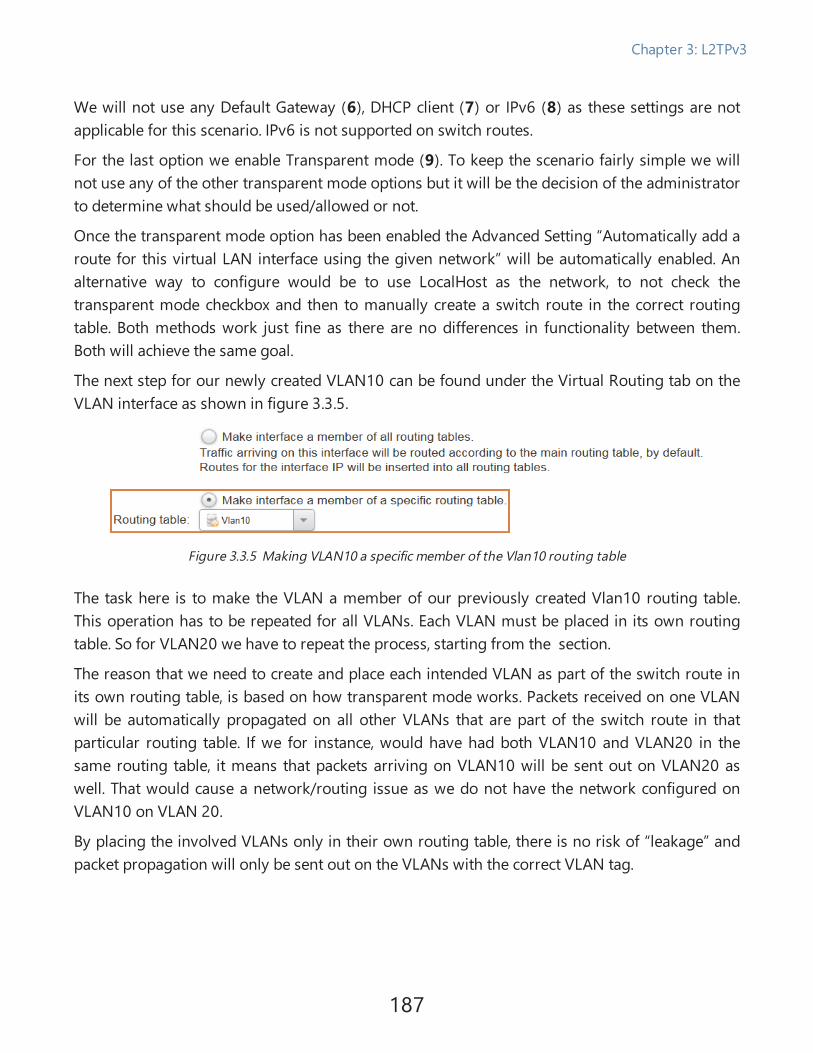
We will not use any Default Gateway (6), DHCP client (7) or IPv6 (8) as these settings are notapplicable for this scenario. IPv6 is not supported on switch routes.
For the last option we enable Transparent mode (9). To keep the scenario fairly simple we willnot use any of the other transparent mode options but it will be the decision of the administratorto determine what should be used/allowed or not.
Once the transparent mode option has been enabled the Advanced Setting “Automatically add aroute for this virtual LAN interface using the given network” will be automatically enabled. Analternative way to configure would be to use LocalHost as the network, to not check thetransparent mode checkbox and then to manually create a switch route in the correct routingtable. Both methods work just fine as there are no differences in functionality between them.Both will achieve the same goal.
The next step for our newly created VLAN10 can be found under the Virtual Routing tab on theVLAN interface as shown in figure 3.3.5.
Figure 3.3.5 Making VLAN10 a specific member of the Vlan10 routing table
The task here is to make the VLAN a member of our previously created Vlan10 routing table.This operation has to be repeated for all VLANs. Each VLAN must be placed in its own routingtable. So for VLAN20 we have to repeat the process, starting from the section.
The reason that we need to create and place each intended VLAN as part of the switch route inits own routing table, is based on how transparent mode works. Packets received on one VLANwill be automatically propagated on all other VLANs that are part of the switch route in thatparticular routing table. If we for instance, would have had both VLAN10 and VLAN20 in thesame routing table, it means that packets arriving on VLAN10 will be sent out on VLAN20 aswell. That would cause a network/routing issue as we do not have the network configured onVLAN10 on VLAN 20.
By placing the involved VLANs only in their own routing table, there is no risk of “leakage” andpacket propagation will only be sent out on the VLANs with the correct VLAN tag.
187
Chapter 3: L2TPv3

Now there is only one more step that must be done for the VLAN part and if we take VLAN10 asthe example we must now create VLAN10 again, but this time as shown in figure 3.3.6.
Figure 3.3.6 Creating another VLAN10 but this time with the Base interface set to the L2TPv3 server
The difference between this VLAN and the first one is that the Base Interface (1) is now theL2TPv3 server and not a physical interface. The reason for this is because we need to inform cOSCore that the Network (3) allocated on VLAN10 exists on more than one interface as part of aswitch route.
Since we will not use internet access through the L2TPV3 interface/tunnel there is no need toallocate an IP address on the VLAN towards the L2TPv3 server, so we simply select LocalHost asthe IP address (2).
We repeat the VLAN creation process for VLAN20 as well and make the VLAN20 a member of itsown routing table, same as we did for as for VLAN10, and also create an L2TPv3 VLAN.
188
Chapter 3: L2TPv3

Creating the needed switch and normal routes
Once all VLANs and Routing Tables have been created we should end up with a routing tablesummary as shown in figure 3.3.7.
Figure 3.3.7 The summary of the 3 routing tables
One routing table for each VLAN. We will now go into the Vlan10 routing table as shown infigure 3.3.8 to verify that we have all the required routes for our scenario.
NoteSome may notice that the main routing table is set to ordering “Default” and has the“remove interface IP routes” is set to Yes. This is basically false. The Main routing table isnot affected by these options. It will make more sense if we consider these two optionsfor the main routing table to be either blank or that the text “n/a” or “Not Applicable”would be present instead.
Figure 3.3.8 The contents of the Vlan10 routing table
189
Chapter 3: L2TPv3

For our Vlan10 routing table we have a total of 3 routes. The two switch routes are eitherautomatically created by the VLAN interface themselves, if the option “Enable TransparentMode” is enabled, or created manually by the administrator. In our scenario they areautomatically added by the interface as we enabled the transparent mode option.
The route at the top however is a bit special. This route we have added manually into this routingtable. The reason why we added this route is because want users located behind the StockholmFirewall to be able to access the Internet using the Stockholm Firewall’s normal Internetconnection. If this route were missing, it would mean that there would be no path in this routingtable to the Internet and the Vlan10 users would only be able to talk to the Vlan10 network andnothing else.
When it comes to the external Wan interface it has not been made a member of a specificrouting table on the Virtual Routing’s tab on the interface but is left at its default value as shownin figure 3.3.9.
Figure 3.3.9 The Wan interface is not a specific member of any routing table
The reason for this is because the Wan interface has to be present in all the Vlan routing tables inorder to tell each routing table and VLAN how to gain access to the Internet.
This of course means we are mixing layer 2 and 3 routing, which may not always be advisable,but for this scenario it will work just fine.
We repeat the route verification for the Vlan20 routing table as well and add the “all-nets” routefor the Wan interface as shown in figure 3.3.10.
Figure 3.3.10 The contents of the Vlan20 routing table
190
Chapter 3: L2TPv3

Creating the required IP policy rules
The last thing we need to do is to create the required IP Polices to allow the traffic to/from theVLAN on either side of the L2TPv3 interface as well as external Internet access. The rules neededfor VLAN10 are shown in figure 3.3.11.
Figure 3.3.11 The IP policy’s needed for internal and external access for the VLAN10 interface
These rules allows users behind VLAN10 either locally or beyond the L2TPv3 server access totheir own network segment as well as Internet using the Wan interface. We are also using “all_services” which should only be used for testing purposes. For live environments it isrecommended to use only the ports/services that should be allowed to/from the variousinterfaces and networks.
A similar set of IP Policy rules must also be added for VLAN20.
The reason why we do not create IP policy rules for access between VLAN10 and VLAN20 is dueto our requirement stated earlier, that communication between separate VLANs should not beallowed in this scenario.
Configuring the London Firewall (client)Configuring the London Firewall is pretty much identical to configuring the Stockholm Firewall.The only difference is that the L2TPv3 client is used instead of the server when attaching theVLANs. All the details on the how the client should be configured can be found in Recipe 3.2.Bridging a layer 2 network using L2TPv3 & IPsec. There will be no changes on how the client isconfigured.
In order to avoid repeating the same description again we will perform a quick summary of theconfiguration of the London Firewall.
191
Chapter 3: L2TPv3

Creating the routing tables
We create two new routing tables. The routing tables will use Ordering “Only” and will be calledVlan10 and Vlan20.
Creating the VLANs
We create four new VLANs with the properties shown in Table 3.3.12.
Name Base Interface NetworkRoutingTable
Transparentmode
AutoAddRoute
Vlan10_lan Lan Vlan10_net Vlan10 Enabled Enabled
Vlan10_L2TPv3 L2TPv3_Client Vlan10_net Vlan10 Enabled Enabled
Vlan20_lan Lan Vlan20_net Vlan20 Enabled Enabled
Vlan20_L2TPv3 L2TPv3_Client Vlan20_net Vlan20 Enabled Enabled
Table 3.3.12
Creating the needed switch and normal routes
As the routes for the switch route has been created automatically by the various interfaces in theprevious step, we need to add only the “all-nets” route to each routing table on order for usersbehind VLAN 10 and 20 to reach the internet using the ISP in London as shown in tables 3.3.13and 3.3.14.
Routing table Vlan10:
Type Interface Network Gateway
Route Wan All-nets wan_gw
Switch Route Vlan10_L2TPv3 Vlan10_net
Switch Route Vlan10_Lan Vlan10_net
Table 3.3.13
192
Chapter 3: L2TPv3

Routing table Vlan20:
Type Interface Network Gateway
Route Wan All-nets wan_gw
Switch Route Vlan20_L2TPv3 Vlan20_net
Switch Route Vlan20_Lan Vlan20_net
Table 3.3.14
Creating the required IP policy rules
The IP Policies needed are the same as on the Stockholm Firewall and are shown in the belowtable:
Src iface Src net Dest iface Dest net ServiceAddress
Translation
Vlan10_Lan Vlan10_Net Vlan10_L2TPv3 Vlan10_Net All_Services
Vlan10_L2TPv3 Vlan10_Net Vlan10_Lan Vlan10_Net All_Services
Vlan10_Lan Vlan10_Net Wan All-nets All_Services SRC:NAT
Vlan20_Lan Vlan20_Net Vlan20_L2TPv3 Vlan20_Net All_Services
Vlan20_L2TPv3 Vlan20_Net Vlan20_Lan Vlan20_Net All_Services
Vlan20_Lan Vlan20_Net Wan All-nets All_Services SRC:NAT
Table 3.3.15
Using “All_Services” should only be used for testing purposes and should be restricted onceeverything is up and running according to specification. Locking down the amount of open portsand protocols is always recommended.
193
Chapter 3: L2TPv3

Requirement checkThis concludes this recipe. As a last step we will look through the initial requirements to see ifthey can now be met. We will go through them one by one.
l Clients on each side should be able to communicate with their peers as if they were locatedlocally. Meaning a client located behind VLAN 10 in London should be able tocommunicate with VLAN 10 in Stockholm.
o By configuring the switch routes, we tell cOS Core on both London and Stockholmthat the network(s) defined on the switch routes exist behind two interfaces, onebehind a local physical interface and the other past the L2TPv3 client/server. cOSCore will keep track of the locations of the various host using the CAM table (seeRecipe 3.2. Bridging a layer 2 network using L2TPv3 & IPsec for more informationabout the CAM table) and if the host cannot be found locally it will forward the querythrough the L2TPv3 interface and (hopefully) locate the target host there. cOS Corewill then add an entry in the CAM table of where the target host MAC address islocated.
We also make sure that the routing is correct (e.g. Figure 3.3.10) and our rule policy’s(e.g. Figure 3.3.11) to allow only the traffic that we want between the transparentgroup we have defined (the local VLAN and the L2TPv3 client & server interfaces).
Status: Fulfilled.
l Intercommunication between the two VLAN networks should not be allowed, only VLAN10should be able to talk to VLAN10 either locally or through the L2TPv3 tunnel, same withVLAN20.
o There are two ways we have restricted communication between VLAN10 andVLAN20. The first restriction was made when the routing tables Vlan10 and Vlan20(see Figure 3.3.8 and Figure 3.3.10 ) contain only the routes related to their ownVLANs.
The second restriction was in our IP policy rules that allow communication onlyto/from the VLAN10 network to the VLAN10 network or towards the Internet (see
194
Chapter 3: L2TPv3

Figure 3.3.11 and Table 3.3.15)
Status: Fulfilled.
l Clients on each side should have internet access that uses their own firewalls. Clients inLondon should use the London firewall’s ISP to surf the Internet, same in Stockholm.Meaning that Internet access will not be forwarded or sent through the tunnel.
o This is primarily achieved by having the route towards the Internet (the all-netsroute) in each VLAN routing table on each site point to the external/Wan interface ofthe Firewall and not e.g. the L2TPv3 interface (see e.g. Figure 3.3.8 and Figure 3.3.10).The IP policy rules are also enforcing Internet access to only be possible using theexternal/Wan interface (see e.g. Figure 3.3.11).
Status: Fulfilled.
195
Chapter 3: L2TPv3

Appendix A - Troubleshooting rules androute problems using Ping Simulations.PurposeThe purpose of this appendix is to discuss some of the common issues as well as tips and trickswhen trying to locate problems related to rules or routing.
We will not describe any specific scenario, except to use a basic setup as base for the examples,but we will list some of the common problems customers have run into as well as a smallquestion and answers section.
We will only be using the CLI as ping simulations are only possible to perform using the CLI.
Detailed Discussion
Ping simulations, what is it?A ping simulation is basically a rule or route tester. Using the CLI command “ping” with variousoptions we can simulate that a packet goes through rules and routing and then print the result.
This is an extremely powerful “tool” to help determine whether a rule or route triggers as itshould or when performing tests to see whether we have any potential “leaks” in the networkwhere we want to make sure that access to a specific network segment is only possible from thedesired source.
Scenario environmentIn order to make a few examples on how the ping simulation can be used we will use thescenario described in Recipe 2.3. A basic IPsec Lan to Lan tunnel scenario. Figure A-1 shows aslightly modified schematic from Recipe 2.3. A basic IPsec Lan to Lan tunnel scenario scenariobut with some additional network details to make the examples easier to follow.
196
Appendix A - Troubleshooting rules and route problems using Ping Simulations.

Figure A.1 The environment which we will use for the various ping simulation examples
Rules and routes in StockholmWe will base the examples of using the CLI in Stockholm. The current rule policies and routingconfiguration in Stockholm are shown in figure A-2 and A-3.
Rules:
Figure A.2 The rule setup on the Stockholm Firewall.
197
Appendix A - Troubleshooting rules and route problems using Ping Simulations.

Routes:
Figure A.3 The current state of the routing table on the Stockholm Firewall
CLI output of the above routes:Stockholm:/> routesFlags Network Iface Gateway Local IP Metric------ ------------------ -------------- --------------- --------------- ------
192.168.150.0/24 London_Tunnel 90203.0.113.0/24 Wan 1000.0.0.0/0 Wan 203.0.113.1 100192.168.100.0/24 Lan 100
198
Appendix A - Troubleshooting rules and route problems using Ping Simulations.

Ping simulation parameter listThe CLI command ping has quite an extensive list of options, we will go through them one byone and what they mean. A summary of all the options / parameters is listed below:
1. -6 Force IPv6.
2. -count=<1...10> Number of packets to send. (Default: 1)
3. -length=<2...8192> Packet size. (Default: 4)
4. -pbr=<table> Route using PBR Table.
5. -port=<0...65535> Destination port of UDP or TCP ping.
6. -srcif=<interface> Pass packet through the rule set, simulating thatthe packet was received by <srcif>.
7. -srcip=<ip address> Use this source IP.
8. -tcp Send TCP ping.
9. -tos=<0...255> Type of service.
10. -udp Send UDP ping.
11. -verbose Verbose (more information).
12. <String> IP address or URL of host to ping.
1. The “-6” parameter means that we tell the Firewall to treat the ping request as if the networkonly consists of IPv6. Any IPv4 related route will not be consulted.
2. The “-COUNT” parameter defines the number of packets we want to send. The default issending one packet but we can send up to 10 in one request. Can be useful in case we are tryingto track a packet loss problem in the network.
3. The “-LENGTH” parameter defines the length & size of the packet. If we send a ping withoutthis parameter it will be a 4 byte ICMP packet. The command can be useful in cases where thereis an MTU or MSS (segment size) problem in the network and we want to try various packet sizesto try to narrow down the problem.
4. The “-PBR” parameter can be used if we want the route lookup to be done in a specific routingtable.
199
Appendix A - Troubleshooting rules and route problems using Ping Simulations.

NoteCannot be combined with the “–SRCIF” parameter because the source interface routingtable membership is already determined when we define the routing table.
5. The “-PORT” parameter determines which destination port that should be used for thesimulation. This can be very useful when combined with the “-TCP” flag to simulate a packetbeing sent on e.g. HTTP (TCP port 80). More examples on this further down.
6. The “- SRCIF” parameter is probably the most important parameter. When using thisparameter we can get detailed information about which rule and routing the specified trafficpasses (or is dropped by). We will go into examples on this further down.
7. The “-SRCIP” is commonly combined with the “-SRCIF” flag to make the ping simulation use aspecific IP. This is extremely useful if troubleshooting problems related to a specific machine. Ifnot specified, the default IP will be the interface IP of the sending interface. We will go intoexamples on this further down.
8. The “-TCP” parameter makes it possible to use “ping” to simulate TCP traffic. Must becombined with the –PORT option. We will go into examples on this further down.
9. The ”–TOS” parameter is a way to set the ”Type Of Service” flag in a packet. It can be used tosend simulation packets with a specific TOS value set in the IP header. It can for instance be usedif we want to test systems that can map IP DSCP for traffic prioritization. DSCP is a subset of theDiffServ architecture where the Type of Service (ToS) bits are included in the IP packet header. IncOS Core this is possible to configure using Traffic Shaping Pipe Rules.
10. The –UDP” parameter is similar to “-TCP”, must also be combined with the –PORT option.
11. Using the –VERBOSE” parameter will make cOS Core print additional details regarding theresulting command output. We will be using the “-VERBOSE” flag in all our scenarios/examplesbelow.
12. The “STRING” means basically the target host we want to reach using our simulation. It canbe placed pretty much anywhere in the ping syntax and is not order dependent. It can be both IPor an FQDN/DNS name.
200
Appendix A - Troubleshooting rules and route problems using Ping Simulations.

Ping simulation example 1
Objective:
Ping a host on the internet using the verbose flag and ICMP.
Ping simulation syntax:Ping 198.51.100.50 -verbose
Output:Sending 1 4-byte ICMP ping to 198.51.100.50 from 203.0.113.100... using route "0.0.0.0/0 via Wan, gw 203.0.113.1" in PBR table "main"
ICMP Reply from 198.51.100.50 seq=0 time= 47 ms TTL=54Ping Results: Sent: 1, Received:1, Avg RTT: 47.0 ms
Result analyzation:
This simulation is the simplest of them all, we tell the Firewall to send a ping to the target hoston the Internet using the verbose flag. The Firewall will perform a route lookup to find the targethost and since this host is a public IP address not routed on any of the local interfaces (see figureA-3), it will match the all-nets route (0.0.0.0/0). This route has a default gateway defined so it willalso use the Gateway address 203.0.113.1 to reach the target host. Since we do not have anyother PBR tables, PBR rules or otherwise the PBR table will in all our examples be “main”.
The last two lines contains information regarding the reply (if any) and the time it took for thereply to arrive. In this case the request and reply (put together) took 47 milliseconds to returnand the average round-trip time (RTT) was 47.0 ms (as we only sent one packet).
201
Appendix A - Troubleshooting rules and route problems using Ping Simulations.

Ping simulation example 2
Objective:
Ping a host on the Internet using the verbose flag, simulate that the traffic was initiated from asecondary IP address on the Firewall.
Ping simulation syntax:Ping 198.51.100.50 -srcip=203.0.113.101 -verbose
Output:Sending 1 4-byte ICMP ping to 198.51.100.50 from 203.0.113.100
... using route "0.0.0.0/0 via Wan, gw 203.0.113.1" in PBR table "main"
ICMP Reply from 198.51.100.50 seq=0 time= 43 ms TTL=56Ping Results: Sent: 1, Received:1, Avg RTT: 43.0 ms
Result analyzation:
Similar to the first ping simulation we send a ping request to the target host, the difference withthis simulation is that we are using a different IP sender by specifying the –SRCIP parameter.Please note that this only works if the Firewall owns the IP address in question (and replies toARP etc.). It will not work if you specify a sender that the Firewall cannot use or respond to.
202
Appendix A - Troubleshooting rules and route problems using Ping Simulations.

Ping simulation example 3
Objective:
Ping a host on the Internet using the verbose flag, simulate that the traffic was initiated from ahost behind the LAN interface.
Ping simulation syntax:Ping 198.51.100.50 -srcif=Lan -srcip=192.168.100.50 -verbose
Output:Rule and routing information for ping:PBR selected by rule "iface_member_main" - PBR table "main"
allowed by rule "Ping_Internet"
Sending 1 4-byte ICMP ping to 198.51.100.50 from 203.0.113.100sent via route "0.0.0.0/0 via Wan, gw 203.0.113.1" in PBR table "main"
ICMP Reply from 198.51.100.50 seq=0 time= 10 ms TTL=56Ping Results: Sent: 1, Received:1, Avg RTT: 10.0 ms
Result analyzation:
This ping simulation is probably the most common simulation used when troubleshooting.When we combine the –SRCIF and –SRCIP parameter we can get cOS Core to make a completerule and route simulation. cOS Core will simulate that a packet is received on a specific interfacewith a specific sender and even send the packet itself to the target host to see if it will reply(198.51.100.50 in this example), then provide detailed output to the administrator about whichrule that triggered. In this case, the “Ping_Internet” rule was the involved rule and since the hostis on the Internet, it used the All-nets route and the Wan interface.
203
Appendix A - Troubleshooting rules and route problems using Ping Simulations.
NoteIn the above simulation we specify a source IP address. The Firewall will pretend that itis this IP address for the simulation. When the return traffic (if the server host replies)arrives from the server to the Firewall, the Firewall pretends to be the specified sourceIP for simulation purposes. The source IP address host will never be consulted orcontacted (which in this example is 192.168.100.50).
Addendum:
Ping simulations show traffic sent through the Firewall. We use the term receive when we talkabout the traffic that arrives to the Firewall, rather than the traffic that arrives at the ultimatedestination.
204
Appendix A - Troubleshooting rules and route problems using Ping Simulations.

Ping simulation example 4
Objective:
Ping a host on the Internet using the verbose flag, simulate that the traffic was initiated from ahost behind the LAN interface and that the target service was a HTTP server using port 80 andTCP.
Ping simulation syntax:ping 198.51.100.50 -srcif=Lan -srcip=192.168.100.50 -verbose -tcp -port=80
Output:Stockholm:/> Rule and routing information for ping:
TCP: 192.168.100.50:62265 -> 198.51.100.50:80 PBR selected by rule"iface_member_main" - PBR table "main"TCP: 192.168.100.50:62265 -> 198.51.100.50:80
allowed by rule "NAT_To_Internet_Http_all"
Sending 0-byte TCP ping to 198.51.100.50:80 from 203.0.113.100:62265sent via route "0.0.0.0/0 via Wan, gw 203.0.113.1" in PBR table "main"
TCP Reply from 198.51.100.50:80 to 192.168.100.50:62265 seq=0 SYN+ACKtime= 10 ms TTL=53TCP Reply from 198.51.100.50:80 to 192.168.100.50:62265 seq=0 FINtime= 20 ms TTL=53
TCP Ping Results: Sent: 1, RST/ACKs Received:1, Loss: 0%, Avg RTT: 20.0ms
Result analyzation:
This simulation is an extension of the previous simulation where we add the use of –TCP and–PORT as well to make a more “life-like” simulation as if a user attempted to surf to a particularhost using HTTP port 80. The –TCP flag specifies that the protocol should be TCP and the –PORTwhich destination port we want to use.
Since a regular Ping is ICMP it’s not really a ping in this case but cOS Core will go through all therule and routing information as if it was an HTTP connection from a client located behind theLAN interface. The result is that the ping simulation will verify whether it works or not by tryingto complete the 3-way TCP handshake.
205
Appendix A - Troubleshooting rules and route problems using Ping Simulations.

It will not be able to make an actual HTTP connection but it can complete the first part of theconnection establishment and give the administrator valuable information in the process.
In our example we got a reply from the server where the handshake was partially completed,long enough for the simulation to conclude it is working. The exact handshake process looks likethis:
1. Firewall: SYN
2. Server: SYN+ACK
3. Firewall: FIN+ACK
4. Server: FIN+ACK
5. 5. Server: ACK
Since we do not want to complete the handshake we send a FIN+ACK on the third packet to theserver to tell the server it can kill the connection. Since the connection is only used for testingthere is no reason why the server should keep this connection attempt open so we request thatthe server close it. Basically a nice way to tell the server to close a connection that is no longerneeded.
206
Appendix A - Troubleshooting rules and route problems using Ping Simulations.

Ping simulation example 5
Objective:
Verify that traffic initiated from behind the Lan interface can be sent into the IPsec tunnel andthat we get a reply.
Ping simulation syntax:ping 192.168.150.50 -srcif=Lan -srcip=192.168.100.100 -verbose
Output:Rule and routing information for ping:
PBR selected by rule "iface_member_main" - PBR table "main"allowed by rule "Stockholm_To_London"
Sending 1 4-byte ICMP ping to 192.168.150.50 from 192.168.100.100sent via route "192.168.150.0/24 via London_Tunnel, no gw" in PBR table
"main"
ICMP Reply from 192.168.150.50 seq=0 time= 23 ms TTL=5Ping Results: Sent: 1, Received:1, Avg RTT: 23.0 ms
Result analyzation:
In the above syntax we pretend that a client with IP 192.168.100.100 located behind the Laninterface wants to reach 192.168.150.50 which is routed behind the IPsec tunnel interface. Theoutput shows that the IP policy rule “Stockholm_To_London” triggers and allows the traffic aswell as the route triggered is using the interface called “London_Tunnel”. This is the name of theIPsec interface used to connect the Stockholm to London networks together. The “no gw” meansthat there is “no gateway” used for this communication as the there is no need for a gatewaytowards a VPN tunnel interface.
And the last entry shows that we got a reply to our ping request, so everything seems to beworking fine.
207
Appendix A - Troubleshooting rules and route problems using Ping Simulations.
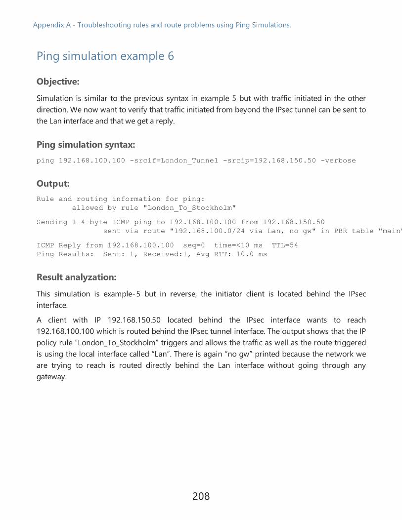
Ping simulation example 6
Objective:
Simulation is similar to the previous syntax in example 5 but with traffic initiated in the otherdirection. We now want to verify that traffic initiated from beyond the IPsec tunnel can be sent tothe Lan interface and that we get a reply.
Ping simulation syntax:ping 192.168.100.100 -srcif=London_Tunnel -srcip=192.168.150.50 -verbose
Output:Rule and routing information for ping:
allowed by rule "London_To_Stockholm"
Sending 1 4-byte ICMP ping to 192.168.100.100 from 192.168.150.50sent via route "192.168.100.0/24 via Lan, no gw" in PBR table "main"
ICMP Reply from 192.168.100.100 seq=0 time=<10 ms TTL=54Ping Results: Sent: 1, Received:1, Avg RTT: 10.0 ms
Result analyzation:
This simulation is example-5 but in reverse, the initiator client is located behind the IPsecinterface.
A client with IP 192.168.150.50 located behind the IPsec interface wants to reach192.168.100.100 which is routed behind the IPsec tunnel interface. The output shows that the IPpolicy rule “London_To_Stockholm” triggers and allows the traffic as well as the route triggeredis using the local interface called “Lan”. There is again “no gw” printed because the network weare trying to reach is routed directly behind the Lan interface without going through anygateway.
208
Appendix A - Troubleshooting rules and route problems using Ping Simulations.

Ping simulation example 7
Objective:
So far we have only run simulations that works as expected, but the most common thing wewant to catch in a simulation is problems. So let’s start with a very common problem whenworking with networking, a typo.
Ping simulation syntax:ping 192.167.100.100 -verbose
Output:Sending 1 4-byte ICMP ping to 192.167.100.100 from 203.0.113.100... using route "0.0.0.0/0 via Wan, gw 203.0.113.1" in PBR table "main"
Ping Results: Sent: 1, Received:0, Loss: 100%
Result analyzation:
This is a bit odd, why would traffic to the internal network go out on the internet instead of theLAN interface? The problem is a typo in the ping simulation itself, we used 192.167.x instead of192.168.
The result is that the cOS Core was unable to find this network on either the LAN interface or theIPsec tunnel and then the all-nets route matched and cOS Core forwarded the request to itsdefault gateway. If we are unlucky we may get a reply in the event that the IP address that weused by mistake, is used by something that actually responds and that would cause confusion ifwe were not observant.
We would also have received a similar result had the typo been on the route itself. Meaning evenif we were to enter the correct IP address on the ping command, the ping would be sent to theInternet route as the Firewall was unable to find this network behind any of the local or IPsecinterfaces.
209
Appendix A - Troubleshooting rules and route problems using Ping Simulations.

Ping simulation example 8
Objective:
A log entry everyone will run into sooner or later is a log that contains “Default_Access_Rule”.For this example we will give a sample on how we can get this entry and what it means. Foreasier understanding please have a look at the CLI output under figure A-3 as reference.
Ping simulation syntax:ping 192.168.150.1 -srcif=Lan -srcip=192.168.101.10 -verbose
Output:Rule and routing information for ping:PBR selected by rule "iface_member_main" - PBR table "main"
DROPPED by rule "Default_Access_Rule"
Result analyzation:
If we first look at the syntax we see that for this sample we introduced a mistake in the pingsimulation. We used the source IP 192.168.101.10 instead of 192.168.100.10 which is thenetwork routed behind the Lan interface.
We tell the Firewall to simulate that traffic is received on the Lan interface with the source IP192.168.101.10 and it gives us the output of what would happen if that were the case. And it tellsus that the result is that it is dropped by the “Default_Access_Rule”. This is actually a really goodlog entry to get because it is always a routing problem and it is very easy to explain why this ishappening.
It means that the packet received on the receiving interface (in this case the Lan interface) is notrouted on this interface. When examining logs, always look for the source/receiving interfacewhere the packet was received, it always means that the Firewall did not expect this packet toarrive on this interface based on the routing and drops it due to the “Default_Access_Rule”.
If we look at the output result and match it against the routing CLI output in figure A-3, we seethat the Firewall expects that the source interface should be Wan and not Lan.
210
Appendix A - Troubleshooting rules and route problems using Ping Simulations.

Addendum:
Ping simulations show traffic sent through the Firewall. We use the term “receive” when we talkabout the traffic that arrives at the Firewall, rather than the traffic that arrives at the ultimatedestination.
Ping simulation example 9
Objective:
A second log message that is also very common is called “Default_Rule” or “Default_Drop_Rule”.This example will trigger this message and we will go through what it means.
Ping simulation syntax:ping 198.51.100.50 -srcif=Lan -srcip=192.168.100.50 -tcp -port=8080 -verbose
Output:Rule and routing information for ping:TCP: 192.168.100.50:11815 -> 198.51.100.50:8080 PBR selected by rule
"iface_member_main" - PBR table "main"TCP: 192.168.100.50:11815 -> 192.36.125.18:8080 DROPPED by rule "Default_Rule"
Result analyzation:
In this simulation we attempt to ping a host on the Internet from the internal machine192.168.100.50 located behind the Lan interface. We also want to use TCP and port 8080, theresulting output is that this is not allowed but instead dropped by a rule called “Default_Rule”.
The “Default_Rule” is a hidden rule that triggers if no IP rule/policy can match the traffic we wantto simulate. If we look at the ruleset shown in Figure A-2 we see that from the Lan interface weallow pinging of the Firewall, Ping towards internet, making DNS queries and to surf the webusing HTTP and HTTPS but not to connect to the Internet on port 8080. However, had thedestination network we wanted to reach been the network routed behind the IPsec tunnel, thetraffic would have been allowed by the rule called “Stockholm_To_London”.
The problem is that there is no matching IP rule/policy created that allows the client to connectto port 8080 on the target IP address. Some administrators create a specific drop rule at the endof each ruleset that drops all traffic instead of the “Default_Rule” being triggered. A common
211
Appendix A - Troubleshooting rules and route problems using Ping Simulations.

name for such a rule is “DropAll”. The reason why we would like to create/use such a rule is insituations where we have multiple rulesets and it will be that much easier to separate of weknow exactly which of the Drop rules that triggered for troubleshooting purposes. Having a dropon a rule called e.g. “Drop_Vlan100” is a lot easier to track/spot than drops that are done by the“Default_Rule”.
Ping simulation example 10
Objective:
The last simulation example output is of the more unusual kind but if we are dealing with a morecomplicated routing environment, it may be encountered.
Ping simulation syntax:ping 198.51.100.50 -verbose
Output:ping: No route to 198.51.100.50
Result analyzation:
What happened here is that when cOS Core attempted to find a route where the target IP islocated is was unable to find any matching route at all. The easiest example of when we can getthis is if we do not have a default route (all-nets) in the routing table the ping simulation is using.
As an example we will get this message if we remove route #3 as shown in Figure A-3.
212
Appendix A - Troubleshooting rules and route problems using Ping Simulations.

Questions and Answers
Question:
Why do we need to specify source interface for the simulation to get rule details? Is it notenough to just specify the source IP?
Answer:
No, if we only specify the source IP cOS Core will assume this IP address belongs to cOS Coreitself. If we specify both source IP and source interface (also known as receiving interface) cOSCore knows it should simulate that a packet was received on the specified interface and then gothrough both the route and rule process and print the resulting output.
Question:
When I used a ping simulation the resulting output was very strange, it said that the destinationinterface was Core and the result is always 100% packet loss even though I know the target hostis alive.
Answer:
The most likely reason for this output is because the ping simulation goes through an IP rule orPolicy that uses an ALG (Application Layer Gateway). Since an ALG acts as a kind of proxy theping simulation output will be unable to properly display the resulting output. This is a limitationin the ping simulation. An example on how it can look:ping 198.51.100.50 -srcif=Lan -srcip=192.168.100.50 -verbose -tcp -port=80
Rule and routing information for ping:TCP: 192.168.100.50:16491 -> 198.51.100.50:80 PBR selected by rule
"iface_member_main" - PBR table "main"TCP: 192.168.100.50:16491 -> 198.51.100.50:80
allowed by rule "NAT_To_Internet_Http_all"
Sending 0-byte TCP ping to 198.51.100.50:80 from 192.168.98.24:16491sent via route "0.0.0.0 via core, no gw" in PBR table "main"
TCP Ping Results: Sent: 1, RST/ACKs Received:0, Loss: 100%
The simulation can still be useful as the data regarding which rule that triggers can be of interestbut the route information is invalid as the real destination interface would not be Core.
213
Appendix A - Troubleshooting rules and route problems using Ping Simulations.

Appendix B – IPsec IKE version 1 tunnelsetup flowchart.PurposeThe purpose of this flowchart is to give an rough understanding of the various phases and stepsneeded for an IKEv1 tunnel negotiation using a pre- shared key (with additional optionexamples).
It can be very useful when troubleshooting a tunnel to know what kind of settings and optionsare verified in each phase. An example would be if the tunnel fails in phase-2 we do not have tobother spending time on verifying if the ID list or IKE proposal list has a match as that part of thenegotiation has already been completed before we end up in phase-2.
214
Appendix B – IPsec IKE version 1 tunnel setup flowchart.

Figure B.1 An example of an IKEv1 tunnel setup using Pre-shared key
215
Appendix B – IPsec IKE version 1 tunnel setup flowchart.

AfterwordThoughts from the AuthorWe have now reached the end of the second cOS Core Cookbook. I hope that you have found ituseful in furthering your knowledge of all things VPN related. The number of scenarios thatexists for VPN and in particular IPsec is very vast, and we have only covered some of the morecommon cases. With the help of the information provided in this Book, I hope that you will beable to adapt the knowledge to even more advanced scenarios.
Some may wonder why we do not cover L2TP, PPTP or SSL VPN in the Book. The first twomentioned protocols are using technologies that are becoming old and obsolete, and somemajor vendors have already discontinued the use of PPTP. I suspect that L2TP is soon to join thatcategory as well. SSL VPN however, is still a fully valid VPN type and we will consider adding it toa future edition of the Book depending on popular demand.
And last, but not least, don’t forget that ping simulations are your friend when troubleshooting.
Best regards,Peter Nilsson.
216
Afterword

Alphabetical IndexAAppendix A 196, 214
CCertificate
CA 112Certificate request 128Chains 114Host Certificate 115Importing and Exporting 120Local and Remote 120Root Certificate 115Self-signed 117
Certificate Authority 112Certificates 34, 111Config mode pool 73Content Addressable Memory 177
DDiagrams 8
EEncryption 9
HHQ setup 93
IID Lists 116, 132IKE 17IKE negotiation 21IKEv2 66Internet through IPsec 142Introduction 7IPsec 15
Certificates 34
217

Connection between local and remote net 101IKE 17IKEv2 66Lan to Lan 43Local ID 24Local network 24Phase-1 21, 49Phase-2 22, 53Properties 24Remote Endpoint 28Remote ID 24Remote network 24Roaming 69SA 19Transport Mode 26Tunnel Mode 25
IPsec explained 16IPsec negotiation 22
KKey Distribution 11
LL2TPv3 159
Passthrough options 161Points of interest 160VLAN 181
Local User Database 77
NNAT Traversal 36
PPing simulation 196
Parameters 199Planning 10
RRoad Warrior 69
SScreenshots 8Security Associations 19
218

Split tunneling 86Switch routes 164
TTransparent mode 164
UUser Authentication 78
VVirtual routing 152VLAN 185
VLAN ID 186VPN introduction 9
219

The Clavister
cOS Core VPN cookbookOnly the tastiest recipes
The second anticipated release of the Clavister cOS Core Cookbook, as edited by network security expert Peter Nilsson, describes some of the basics of encryption and the use of Virtual Private Networks (VPN) to unlock this critical Clavister solution for customers.
The book’s focus is on how VPN can be used in some of the most common scenarios with a strong emphasis on VPN tunnels that use IPsec. It will also describe how Layer 2 tunneling protocol version 3 (L2TPv3) can be used together with transparent mode over an IPsec connection as well as a few tips and tricks on how to troubleshoot rule and routing problems on both physical and VPN interfaces. Taken together, the Cookbook offers structured solutions and improvements to show why Clavister solutions are so well regarded.