
Keynote Henk Nies & Arienne van Staveren over de resultaten van In voor zorg!

The CIVA
© CIVA
Revision 5 ~ March 2017

© CIVA
Commission Internationale de Voltige Arienne
Page 1
Imagine an aerobatic event in progress ...
A 1,000m square "box" area is defined, sometimes even marked-out, on the ground at an airfield. One centre-line (usually parallel to the runway) is called the "A" or main axis, and in one direction this is declared the 'official wind'.
By a big letter "J" about 150m back from one side of the box, up to 20 people sit in pairs on reclining chairs, some gazing at the sky whilst others wield clip-boards and pens. This is called the 'Judging Line'.
One aeroplane busily zooms through a series of darting aerobatic figures with a purpose or design that's not immediately obvious, whilst another gets ready to take-off and wait a mile or so away for its own turn in the box.
Around the club-house and marshalling apron groups of pilots watch the competing aeroplane, walk around with little bits of paper in a world of their own "flying" their hands through their sequence, or just chat idly.
They're having an aerobatic competition, and in due course one pilot will win - while everyone else squabbles about the lesser placings. So just how does this all work, and crucially....
Why do we need to "Judge"?
In an aerobatic competition, to rank the quality of the sequences flown from "best" to "worst" we have to have some judges. Whilst in many sports the winner can easily be determined by who scores the most goals or pots the most balls, who flies the "best" aerobatics is a subjective matter based on observation of every element of the sequence of figures flown and the application of a set of rules or criteria to grade the result.
An internationally agreed format for running aerobatic competitions and judging aerobatic flights has been established and refined by FAI / CIVA over many years. The BAeA is the National Aero Club responsible for running aerobatic competitions for powered aircraft and gliders to these rules in the United Kingdom.

© CIVA
Commission Internationale de Voltige Arienne
Page 2
What do Judges actually do?
In order to decide which pilot is best in a reasonably fair and robust way, it is necessary to:
1. Define exactly what the competitors have to do.
2. Establish a system for measuring how closely the elements in each flight meet this definition.
3. Use the measuring system to judge each competitor's performance against what is required.
Grading or judging an aerobatic sequence is not a simple task, since the figures can be complex and applying the quite precise grading criteria requires not only a good deal of human "judgement" but the speed and skill to keep up with the action. To programme a computer to evaluate an aerobatic sequence in real time would be a huge task. People, on the other hand, can be trained to be very proficient aerobatic judges.
To become a good judge you must understand the rules, develop the skill to apply them to grading aerobatic figures, and be confident in your own judgement. You need not be an 'expert' nor even a pilot. In fact, being unaware of the difficulty the pilot may be experiencing can be an advantage, since the rules require that it is the pilots skill and not the aircraft's ability which is being assessed.
The Judging process
Judging an aerobatic sequence involves assessing the flight path and attitude of the competing aircraft as it flies each figure, comparing what you see with the 'ideal' requirements of the rules to identify discrepancies or errors, applying the appropriate downgrades, and then giving each figure a final 'points score' from zero to ten in half-point steps. The process is essentially an error-spotting routine, the final judgement for each figure being based on 'badness' detected rather than goodness observed. An overall judgement is made of figure positioning during the sequence. Note that the 'harmony' mark for glider classes was abandoned at the CIVA 2016 plenary and is used no more.
Penalties may also be applied for other major rule infringements, and if any part of a figure gets more than 90° away from the intended attitude or is simply judged to be entirely wrong it is awarded a 'Hard Zero'. The Chief Judge has the final say, after consultation with the other Judges, as to whether a figure should get a 'Confirmed Hard Zero' or not, and this will apply to all Judges grades.
What makes a good aerobatic judge?
Well, it isn't particularly difficult - but it does take patience and practice. These BAeA notes describe the basic principles of judging both for potential Judges and interested pilots. The complete official judging procedures are detailed in the current editions of the CIVA Catalogue and the BAeA General Rules for the Conduct of Aerobatic Events. These are obtainable to download from this web or the FAI / CIVA site.

© CIVA
Commission Internationale de Voltige Arienne
Page 3
What does an Aresti diagram look like?
In order to write aerobatic manoeuvres, figures and sequences down on paper so that other people can read, fly and judge them a universal 'language' is essential. The system used throughout the aerobatic world was originally developed by the Spanish aerobatic ace José Louis Aresti.
To become proficient as an aerobatic judge or pilot a good understanding of the CIVA Aresti System (Condensed) is a priority. It has a basic set of "rules" which govern how the symbols are used, and each manoeuvre has an identifying reference number and a numeric coefficient for its difficulty rating, allowing the user to build "K-factors" for composite figures. The catalogue lists the complete range of basic and complementary manoeuvres from which aerobatic figures may be constructed for inclusion in programme I (pilot designed), programme II and III (unknown) sequences to meet the specific requirements of any contest.
The fundamental structure of the “Aresti” aerobatic notation system
Aerobatic figures are made up by combining basic and complementary manoeuvres which are grouped into eight basic "families" (1-8) and one complementary "family" (9) in the CIVA catalogue. Each manoeuvre is depicted by its Aresti symbol.
Power and Glider aerobatic figures are in separate catalogues - the latter differs in many details from the power version.
Family 1 Lines and Angles - Horizontal, 45° & vertical line variations.
Family 2 Turns& Rolling Turns 90°-360° turns erect & inverted, with optional rolls.
Family 3 Combinations of Lines - more of family 1.
Family 4 (no longer used - was originally Spins on their own, now incorporated with Family-9)
Family 5 Stall Turns - the four possible variations.
Family 6 Tail Slides - the eight possible variations.
Family 7 Loops and Eights - Round/square/octagonal loops, split-'S' & 8's.
Family 8 Combinations of Lines, Angles & Loops, Humpty bumps, Cubans and variations
Family 9 Rolls Slow, 2-point, 4-point, 8-point, flicks and spins

© CIVA
Commission Internationale de Voltige Arienne
Page 4
Understanding the notation
The simplest basic figure in the catalogue is the very first - Family 1, line 1, column 1, usually shortened to 1.1.1.1 and shown as figure-1 below. This is drawn as a solid line (denoting erect flight) with a black dot at one end and a short line at right angles at the other, denoting the beginning and end respectively of the figure. To this must be added one or more rolls from Family 9. Slow rolls are drawn as an arc half way along the line, concave to the direction of flight and with an arrow-head denoting direction, or as a triangle with a short line at the apex for flick / snap rolls. The number above the dot refers to the figure number in the sequence.
a) 1.1.1.1 b) 1.1.1.1 + 9.1.3.4 c) 1.1.1.1 + 9.9.3.4
In each case above the (same) basic figure has a difficulty or 'k' factor of 2. The 'k' factor of the complementary figure (the roll) is added to this to produce a total 'K' for the complete figure thus:
Therefore a judge’s mark of 8 for figure (b) would give a contestant a score of 80 (8 x 10) from that judge for that figure; a mark of 7 for figure (c) would give a score of 91 (7 x 13).
Inverted and so-called negative 'G' flight is represented by a pecked or dashed line (in red if possible):
d) 1.1.1.2 e) 1.1.1.3 + 9.1.3.2 f) 1.1.1.4 + 9.10.3.1 + 9.1.3.8
In figure-6 the snap and aileron rolls are shown "opposed" (heads on opposite sides of the line) and so the pilot must fly them in opposite directions - either right then left, or left then right, it doesn't matter which.
The total 'k' factors are added together to produce a total 'K' for the sequence. This may vary in value between (roughly) 60K for the Club sequence to over 450K for an Unlimited program. Part of the challenge for pilots at different levels is the task of designing their own "Free" sequence to an exact total 'K'.
The 'k' factor for every basic and complimentary figure in the Catalogue is derived by a logical set of rules from a series of base values. Discussion of this is outside the scope of these notes but it is all explained in the FAI Aerobatic Catalogue ('Part II - Method of Evaluation').

© CIVA
Commission Internationale de Voltige Arienne
Page 5
The aerobatic "box"
Where do we judge (we mean, other than on cold, windy and frequently wet airfield!)?
All aerobatic figures are judged in and relative to the aerobatic performance zone - we call it the "box". For the Unlimited class this is nominally a 1,000m cube of air with its lower face 100m above the ground, while for more junior classes the base height is raised to 200m, 300m etc. for safety reasons.
The box is defined principally by two land-based axes:
The "A" or main box axis is aligned with the competition wind (flight along this axis will by definition therefore be either into wind or down-wind).
The "B" or cross box axis is set at 90° to the main / "A" axis.
Ideally, box markers on the ground define the centre, corners and edges of the box.
The height above the ground of the minimum allowable flying altitude (the "bottom" or "base" of the box) varies depending on the class of competition being flown – highest for Club, lowest for Unlimited.
Judges sit in line with the "B" axis, but set back about 150m from the nearest edge of the box. This gives them the best vantage point to judge the flights.
The "competition wind" can be from the left or right (always on the main axis) and is declared by the Contest Director or Chief Judge before competition flights start.
The orientation of the box and the wind direction is important – figures must be flown in the correct direction and on axis, so it is important that judges understand the location and orientation of the box.
If a figure is intended to be flown on the main axis (as indicated by the sequence diagram), any deviations from this orientation are penalised by a downgrade of 1 point per 5 degrees of error seen. This applies both to the main "A" axis and the cross "B" box axis. A figure may start on the main axis and finish on the cross box axis or vice-versa; in each stage of the figure, the correct axis orientation must be maintained.
Figures that start on the main or "A" axis must be flown in the correct direction (into wind or down-wind) otherwise the figure is zeroed. This absolute requirement does not apply to figures started on the "B" axis.
Figures that start on the "B" or cross box axis do not have to be flown in a particular direction – although the direction chosen must make sense compared to the sequence diagram.
If a sequence is interrupted (ie. a "break" is taken) before the start of a particular cross box figure then on restarting that figure must be flown in the direction established by the pilot before the break was taken.
Figures that are flown too high, outside the "box" or that start behind the judges are penalised either 'by the book' or under the direction of the Chief Judge. Excursions beyond the four vertical corners of the box are either noted by boundary judges (sitting on the ground 50m outside the four corners of the box) and penalised accordingly, or are reflected in the Positioning or Framing mark awarded to the pilot by each judge.

© CIVA
Commission Internationale de Voltige Arienne
Page 6
The Centre of Gravity Track (CGT)
To judge how well - or badly - the competing aeroplane flies each aerobatic figure we use one or other of two equally important criteria:
The Centre of Gravity Track (explained on this page)
The Zero Lift Axis (explained on the next three pages)
The Centre of Gravity Track (refer to it as the CGT) is the imaginary line that the aircraft centre of gravity draws as it flies along.
Note that the longitudinal neutral axis of the aircraft (i.e. the Zero Lift Axis or ZLA) almost always points away from this track (in pitch and/or yaw) by an amount which depends on the control inputs of the pilot, the wind, and the speed of the aeroplane - usually with larger angles at slower flying speeds.
Imagine the aeroplane condensed into a dot, and watch the path that the dot takes through the sky.
This is the Flight Path, or Track of the aeroplanes' Centre of Gravity.
Judging the flight path involves comparing the observed CGT path against fixed references such as the horizon or the 'A' or 'B' axes of the box.
Example 1
The aeroplane is required to transit from a vertical down-line to horizontal flight. Although the ZLA remains horizontal after the 90° corner has been completed, the CGT will in reality continue to descend a little below the required horizontal line.
Example 2
Here the transit is from a vertical up-line to normal horizontal flight. The CGT must remain in a level horizontal line, whilst the aircraft speed will increase from very slow and the angle of attack reduces accordingly.
Tip - 'screw your eyes up' and just concentrate on the movement of the blurred dot in the sky without moving your head.
It is very useful to hold a finger up to where the horizontal line started, to give you a fixed reference point for the start of the line. A climbing or descending CGT is usually obvious.
CGT and Angle of Attack
Judges must always look at the CGT and not be "fooled" by a high angle of attack at low speed – this can be particularly noticeable when the aeroplane is inverted, as with most aircraft the nose will appear un-naturally high.

© CIVA
Commission Internationale de Voltige Arienne
Page 7
The Zero Lift Axis (ZLA)
The "Zero Lift Axis" of an aircraft is purely a function of its shape and aerodynamic qualities. Think of it as an imaginary line, but this time it is "fixed" to the aircraft and runs through the centre of gravity from nose to tail.
Imagine that an aircraft is flying a true vertical line in still air. The ZLA will now be exactly perpendicular to the ground.
The left sketch shows the aeroplane flying vertically downwards with its ZLA through the pitch axis.
Look at the two plan view 'planes in the centre and clearly the yaw axis is perfectly vertical in both cases.
In the one on the right however the pilot has inserted a little roll and yaw during the preceding pull or push and carefully straightened it up before vertical ZLA was achieved. You can see that a considerable sideways vector to the CGT is possible - this is a key element in the art of keeping the aircraft in the box when it is windy.
Aeroplane silhouette
In different aeroplanes the Zero Lift Axis can be similar to or very different from the line along which the fuselage appears to point. Early aerobatic designs often still had non-symmetrical lifting wings and an upswept floor line behind the pilot, and can seem very nose-forward when flying vertical lines (Tipsy Nipper, Stampe, Pitts etc.) and markedly nose-up when inverted. More modern symmetrically shaped monoplanes (Extra 300, Cap 232, Sukhoi 26 etc.) have been designed to appear to fly with almost the same attitude both ways up. The Schleicher ASK-21 glider in particular displays a marked 'nose-down' attitude that must be carefully considered on vertical lines.
This 'phantom' error is most marked in a stall-turn, where the aeroplane can appear quite noticeably positive on the way up and equally negative on the way down even when it isn't - the bane of a Pitts driver's life .....

© CIVA
Commission Internationale de Voltige Arienne
Page 8
When should we use CGT and when should we use ZLA?
When the aircraft is flying horizontal lines or curving, rotating or rolling manoeuvres you should judge the aircraft on CENTRE OF GRAVITY TRACK (CGT).
When we are judging vertical or 45° lines up or down you should use the aircraft ZERO LIFT AXIS (ZLA)
Note: CGT is therefore used during the course of any rolls placed on vertical or 45° lines.
For rolls placed on a curve, the curved flight path must continue accurately during the roll.
Be aware that aircraft types whose Zero Lift Axis does not pass centrally through the tail will appear to spiral during a perfect roll, even though the ZLA might be bang-on target. The Pitts above shows what to expect.
Tell them what you see! When you see the aeroplane is deviating from accurate vertical or 45° ZLA, you need a way to describe what is happening that the other judges understand, and will also be clear to the pilot when he reads your comments on his judging sheets.
For 45° lines the usual convention is to use Steep if the attitude is more vertical than it should be, or Shallow if it is more horizontal. In vertical lines if the aeroplane is tending toward erect flight then call it Positive up or down, or if it's tending toward inverted flight then call it Negative up or down.
When there's a wind of any kind, the observed flight path when the aeroplane is flying any other lines than purely horizontal ones (ie. in vertical and 45° lines) will be angled from perpendicular to the horizon by some amount. You can hold your finger up to mark the beginning of the upward /
downward line or use your peripheral vision to keep track of the flight path in relation to visible 'fixed' ground features, and you'll recognise this quite easily.

© CIVA
Commission Internationale de Voltige Arienne
Page 9
However, the effect of this wind and/or 'crooked' CGT must be completely ignored by the judge, who should only evaluate the accuracy of the aeroplane's attitude - in other words, judge only the ZLA.
The basic rules of Judging
Every figure starts with a potential 'perfect' mark or grade of 10 points.
Each Judge deducts points (to the nearest ½) from the starting 'bank' of 10 for errors seen, to arrive at his or her personal final mark for each figure. This is a fault driven process - you are not marking "goodness".
On the "A" or main box axis (into or out-of-wind) every figure MUST be flown in the correct direction relative to the official wind. Figures flown in the wrong direction MUST get a 'Hard' zero mark.
On the "B" or cross box axis the direction of flight is not a judging criterion; the pilot can choose either way. At a restart after a break however the original direction of flight MUST be maintained.
Figures must start and end in erect or inverted level flight on the "A" or "B" axis. Powered aircraft must fly with a perfectly horizontal CGT, whilst gliders can fly with their CGT at a consistent angle of glide-slope to maintain speed.
The first figure of any sequence starts as the aircraft leaves horizontal flight. For all subsequent figures, the figure finishes as soon as the aircraft achieves horizontal flight. All flight thereafter belongs to the next figure.
For every 5° of yaw, pitch or roll by which the aircraft CGT or ZLA differs from what is required when starting, at all 'key' points and at the exit from each figure, you should deduct one point. An ‘error’ of 2.5° thus equates to a half-mark downgrade. A cumulative error in any figure of more than 45° must by definition result in a mark of 0.0
In the diagram above:
Radii 'A' and 'E' need not be the same, but 'E' is flown much more slowly.
Lines 'B' and 'D' must be the same length.
For a 2/1 ratio : deduct 2 marks
For a 3/1 ratio : deduct 3 marks
No line at all : deduct 4 marks
For example:
If the aircraft above starts the figure with 5° nose-up, no yaw and between 5° and 10° of bank
During the figure it is pitched OK but yawed 5° and rolled 10° off axis at a key point
It ends with 5° of yaw, between 0° and 5° nose-down and no bank angle
The result is: 10 points - 1 - 0 - 1.5 ... - 0 - 1 - 2 ... - 1 - 0.5 - 0 = 3 marks for that figure A very important point to remember is that the whole aerobatic judging system:
Does NOT reward how "good" a figure looks - this would just be wow-factor judging
It DOES downgrade from a fixed "bank" (10) to penalise specific / observed errors by fixed amounts.
Line lengths and corner radii should generally be 'balanced' in size throughout a figure, with the exception of figures from families 1 & 8, where part loop radii may be different within a figure. However, although the top radius in the

© CIVA
Commission Internationale de Voltige Arienne
Page 10
example above may be smaller than the bottom radius, it should still be flown with a constant radius and not as a sharp corner. It is important that each figure starts and ends in straight and level flight (either erect or inverted). In the absence of a distinct line, 1 point should be deducted from both the first and the second figures.
Remember: 5° equals a 1 point downgrade
This is a fundamental rule to have embedded in your thoughts as you judge. It is used in all figures at some point, even if only for the start and finish. Half point increments (½ or 0.5) are used, so that if your opinion is:
"Between 5° and 10°" then you should deduct 1½ points.
"A noticeable amount but less than 5°" then deduct a ½ point.
Here's an example which could easily cause confusion
Two separate figures – if flown without a clearly recognisable straight line between them – can easily become rolled into one:
And here's a badly flown figure to consider
The aircraft drops sharply during the slow roll. What is the angle between the CGT track and the true horizontal?
Deduct 1 point for each 5° Rolling and Pitching:
For each variation in roll rate: deduct 1 point
For stopping < 45° from the finish: deduct 1 point per 5° that the stop was 'early'
However: a visible stoppage then a continuation in roll must lead to a Hard Zero, as this normally converts a slow roll to hesitation roll. There is one exception - see rolling turns.

© CIVA
Commission Internationale de Voltige Arienne
Page 11
Turns
This is not a PPL turn! The figure is indeed a level turn, however in this case it must not be flown with the usual carefully "co-ordinated" roll-and-yaw. Here we want a crisply started initial roll to establish a bank angle of at least 60 degrees without any change in heading, then immediately a constant rate turn for the whole heading change with no variation in bank angle, to a stop on heading whilst still rolled that is instantly followed by a roll to return to level flight. Think of the jerky actions of a mime artist - that's the style we want.
Roll into the turn:
Start from level flight on heading
Roll briskly to at least 60° with no heading change, i.e. just like the first 60° of a slow roll.
The aeroplane CGT should remain level throughout the roll
Turn:
Constant bank angle
Constant rate of turn
Maintain level (altitude)
Stop on heading
Roll out:
Roll briskly back to wings-level flight
No change in heading!
Constant roll rate
The rate of roll in and out of the turn should be even
What is not judged:
The shape of the turn, this is not a wind corrected figure
The size of the turn
Practical Tips:
Check that the heading is correct at the start of the turn
Be careful of optical effects – the aeroplane will look as if it is climbing when it's coming towards you and descending when it is going away from you.
Think about the direction turned – it matters if the figure is from the “B” axis to the "A" axis.
Look for 'crabbing' at the end of the turn, ie. sliding sideways with off-angle CGT although the ZLA remains correct. The aeroplane should be 'square' to the box and flying directly along the correct axis.

© CIVA
Commission Internationale de Voltige Arienne
Page 12
Rolling Circles
Amazingly, there are 80 variations of the Rolling Circle ... Luckily for us they are all basically similar, and they all follow the same set of rules and judging criteria. The fundamental building blocks are:
There are four different amounts of turn - 90°, 180°, 270° and 360°.
The rolls can be "inwards" where the inner wing goes downwards at the start, or "outwards" where the inner wing goes upwards at the start. Some rolling turns combine both inwards and outwards rolls.
The figure is commenced from erect or inverted flight, on either the "A" or "B" axis. The exit can be either erect or inverted depending on the figure, and must be aligned with a major axis.
In "still" air each roll segment will normally cover 90°, 120°, 180 or 360° of the circle. However, these compass points are NEVER used whilst judging the figure, only the CGT and continuous attitude of the aeroplane.
Start
Level entry, on heading.
Brisk start to first roll.
Throughout
CGT should be horizontal, with constant altitude.
The rate of change of direction throughout the turn should be constant.
The rate of roll must also be constant - if you see a flick-roll then give a Perception Zero.
There should be no pause between any required changes of roll direction.
The required rolls should be completed exactly at the exit point.
Finish
Stop on heading and without any remaining bank angle or yaw.
Marking
For every clear variation in the rate of roll or the rate of turn give a downgrade of half to one point.
Each stoppage in the rate of roll or the turn must receive a downgrade of one to two points.
For climbing or diving errors the deduction is 1 point for each 5° or 100ft (30m) of altitude change from level.
At the start and end points the usual 1 point per 5° downgrade applies to CGT errors in the axis or direction of flight and to mistakes in presentation of the correct wings-level attitude.
Even integration of the rolls may be expected at the end of each roll segment, but this is only a guide as to how well the pilot is co-ordinating the rolls and turn. Do not cumulate errors at the compass points, just concentrate on the start and end points and the regularity and correctness of events throughout.
If the number of rolls is wrong - too many or too few - then give a Hard Zero (HZ).
If a flick-roll is seen at any stage (they should all be slow rolls!) then give a Perception Zero (PZ).

© CIVA
Commission Internationale de Voltige Arienne
Page 13
What is not judged
The shape of the turn, this is not a wind corrected figure.
The size of the turn.
Practical Tips
Check that the heading is correct at the start of the turn.
Be careful of optical effects – the aeroplane will look as if it is climbing when it's coming towards you and descending when it is going away from you.
Think about the direction turned – it matters if the figure is onto the "A" axis.
Always take a moment to check that the required "inwards" (inner wing going down) or "outwards" inner wing going up) roll direction is in the right direction - if the roll goes the wrong way, it's a HZ.
Look for 'crabbing' at the end of the turn, ie. sliding sideways with off-angle CGT although the ZLA remains correct. The aeroplane should be 'square' to the box and flying directly along the correct axis.
Judging the "not so good" rollers …
Rolling circles or turns are one of the most complex figures in the catalogue to judge, and they also happen to be pretty difficult to fly accurately. Throughout the figure, which can last as long as 25 seconds, you must look for and cumulate errors that arise from:
Variations in the angular rate of roll.
Variations in the angular rate of the turn.
Variations on the altitude of the flight path.
The wings-level accuracy of any mid-figure changes in the direction of roll.
The angle of roll at the beginning and especially the end of the figure, where a good deal of yaw angle and 'skidding' of the aeroplane is also likely.
The problem for pilots is that what the rules demand is in reality extremely difficult to achieve. Maintaining the same rate of roll and turn and flying at a fixed altitude while the wings are within 20-30° of level is a very demanding task, as many aeroplanes lack the rudder authority to produce the co-ordinated yaw and turn necessary. A solution often seen is for the pilot to apply extra 'pull' or 'push' during the wings-vertical sectors to co-ordinate the whole picture at the 45° and 90° points, causing two variations in the rate of turn during every half-roll as the aeroplane first trails and then leads the smooth turn that is required.
The problem for judges is that the sheer size and overall timescale of the figure combined with the relatively slow rate of simultaneous roll and turn and height variation make it very difficult to isolate and identify the subtle changes that almost inevitably occur. Applying the fixed downgrades demanded by the rules is much harder than with more snappy figures, the tendency being to err on the safe side and be 'kind' to the pilot. In judging however you must always compare what you actually see against the precise standard required, recognise the errors and subtract the appropriate downgrades; rolling circles are not an exception!

© CIVA
Commission Internationale de Voltige Arienne
Page 14
In reality therefore …
Often you will see something like the sketch above rather than the idealised diagram on the previous page. There will be periods of rolling but with a very low rate of turn while the roll angle is within 20-30° of wings level, interspersed with periods of much higher turn rate as the wings pass through the vertical position where the pilot can use 'pull' and 'push' to bring the total amount of turn up to match the roll. Hold your pencil up in line with the axis of the fuselage to monitor the true rate of turn throughout the figure, and you can clearly see the turn rate rise and fall. The aeroplane may also 'porpoise' up and down, depending on whether the outer wing is above or below the horizon, leading to significant changes in altitude. In the case shown above, assuming that there is a constant roll rate but obvious discrepancies in the rate of turn due to clear evidence of excessive 'pulling' and 'pushing' and also some minor height variation:
Downgrades
Based on the errors in the ‘not so good’ diagram above:
Change in the rate of turn (four times @ 1 point each), 4.0
Variation in height of 100ft (not shown above, but ...), 1.0
Exit flight-path angled about 10° away from the intended axis, 2.0
Final mark: 5.0
In practice, to receive a mark greater than 7.5, a rolling turn must be flown to a very high standard!
Slow Rolls
Slow rolls, many of which include hesitations, are sometimes called aileron rolls to distinguish them from flick or snap rolls.
In a slow roll the rotation is primarily driven by aileron action, whereas a flick roll combines yaw and pitch inputs to cause 'auto-rotation'. Key points:
The start and finish of each element of a roll should be crisp, and each hesitation must be at the correct angle of roll (with the usual 1 point per 5° error deductions).
The rhythm and the rate of roll must be consistent throughout and between any hesitation elements.
The CGT during and after a horizontal roll should be exactly in line with the CGT before it.
Many variations of slow rolls are used in a great variety of figures, often preceded and followed by lines which must be judged for CGT (where horizontal) or ZLA (where at 45° or in the vertical) and also for comparative length.
Height gain or loss during horizontal rolls and barrelling around the required angle of line are obvious errors. If the wrong type of roll is seen (a hesitation is missed or added etc.) then the whole figure is wrong, and it must be awarded a Hard zero mark.

© CIVA
Commission Internationale de Voltige Arienne
Page 15
Judging criteria
The rate of roll must be constant
The roll must be in a constant plane (axial)
Must be no change in direction of flight
Accurate angle stops between elements
Maintain axis in level, 45° or vertical flight
What is not judged
The speed of roll, although in a point roll every element must be at the same rate between hesitations.
Practical tips
Check the heading at the start and end of the roll
Check that the aeroplane does not climb or descend
Look carefully at the end of the roll to make sure that the aeroplane is not crabbed off axis
Look for heading when aeroplane is inverted
Don’t be wowed by speed of roll – this is not a criterion
Accuracy is more important than speed
Penalise "bounced" stops
Look for under or over rotation of the roll
Flick or Snap rolls
Flick rolls (called 'snap rolls' in the USA) are initiated by rapid pitch and yaw control inputs, causing one wing to partially stall whilst the other still flies - leading to instantaneous high acceleration in roll. This abrupt high energy translation makes the manoeuvre hard to study and hence difficult to judge accurately.

© CIVA
Commission Internationale de Voltige Arienne
Page 16
Criteria
At the entry to the manoeuvre the aircraft MUST -
Abruptly pitch positive or negative to briefly set the wings at a critical angle and cause an immediate semi-stalled condition.
Yaw to unbalance the airflow between the wings, and so reduce the critical angle of one wing whilst increasing the other.
The initial 'nod' and yaw (can be together or made as a quick "one-two") must immediately produce rapid "auto-rotation". "Auto-rotation" means that one wing has a higher angle of incidence than the other, is in a stalled condition and thus causing high drag, whilst the other wing has a lower angle of incidence, is not stalled and is still providing lift. In true auto-rotation NO aileron is be required to initiate and drive the rolling motion, if you see “in-flick” aileron applied you might believe that the aeroplane is not really flicking.
Throughout the flick-roll the aeroplane must remain auto-rotating by continued application of the initiating pitch and yaw control inputs. A translation to aileron rolling at any stage before the required angle of rotation has been completed would mean that the flick has ended early – this is a certain 1 point / 5° downgrade.
At the correct angle of rotation the roll should cease abruptly, and the aircraft should continue along an axis closely parallel to the extended pre-roll axis. This stoppage must primarily be driven by reduction in the pitch angle and removal of the yaw to un-stall the wings and restore balanced flight, so once again any aileron applied to stop the roll is not the appropriate control.
Check carefully that the last part of the auto-rotation is not turned into an aileron roll to assist accurate end-stop positioning, a commonly adopted ploy that must be penalised.
Downgrades
Flick-rolls happen so rapidly that it is your subjective 'perception' as to whether the two essential components - pitch and yaw - have been successfully applied to cause auto-rotation, and removed at the right moment to stop it. It is not possible to test the presence/absence of these ingredients from a video, so if you believe they were absent you must use the Perception Zero (PZ) rather than the Hard Zero (HZ).
If the stall is inadequate the aircraft will fly a 'barrelled' roll with both wings providing lift, and considerable sideways translation from the starting axis is likely - this MUST be given a Perception Zero mark.
Don't forget also to check that the manoeuvre you see is positive or negative - whichever one the sequence calls for. If it goes the 'wrong way' it must get a Hard zero.
Aircraft characteristics vary a lot in their requirements for flick initiation, and with some modern types the pitch movement can be quite small. For a given change in pitch angle the tail will move further than the nose, so look for a tail movement towards the wheels for a positive flick (as in the diagram above of a one-turn positive flick in level erect flight) and away from the wheels for a negative figure.
If you see a 'flick' that in your opinion is not primarily driven by pitch and yaw or where aileron input is an obvious factor in driving the roll, then you should give it a Perception zero.
In every other important aspect the penalty to apply is the usual 1 point per 5° of inaccuracy observed.

© CIVA
Commission Internationale de Voltige Arienne
Page 17
Spins
Look particularly for a clean initial stall. If the aircraft lifts and rolls or flicks into the autorotation this indicates clearly that it must have been flying at above stalling speed, and you must then give the figure a Perception zero mark. A smooth and accurate transition from the spin directly into the down line without any aileron assistance is also important.
A 'wrong-direction' (90°, 180° or 270° out) exit on the "A" or "B" axis of course Hard zeros the figure, and on the "A" axis this will be followed by further zeros until the mistaken direction is corrected. Note in the figure shown here that the Aresti symbol shows a negative down-line because without the spin the basic manoeuvre would require a 'push' entry from horizontal.
In a properly executed Spin
you should see -
A clearly visible stall in positive or negative horizontal flight, on the correct heading and without any roll or yaw. The nose should drop without the CGT rising, and at the same moment yaw and roll should begin and lead immediately to autorotation.
The rotation should stop and at the same moment the nose should drop to the vertical (ZLA) with the aeroplane on the right heading. There must be no perceptible aileron roll to establish the correct final down-line axis. Note also there may be a curved trajectory of the down-line, especially in 1¼ and 1¾ spins.
The aircraft should draw a vertical line (ZLA) and then execute a constant radius pull or push through to horizontal flight on the right heading. This clearly shows the decay in forward energy of the aeroplane, from stall-speed to a virtual stop before the final pull.
Downgrades
Is the CGT maintained up to the point of dropping into the spin? Height gain or loss is wrong.
Entry heading, and roll & yaw prior to the stall: 1 point / 5°
The spin entry - does it stall > yaw > drop into the spin properly, or is it flicked or forced? (PZ)
As the spin stops, is it on heading without aileron 'assistance' - 1 point / 5° if not.
Verticality of the ZLA down-line: 1 point / 5° for axis, roll or yaw accuracy.
Rolls on the down-line must follow the spin after a short pause, ie. they are not 'centred'.
Exit line (or it could be a ¾ loop, 45° up or another vertical etc.) - CGT or ZLA criterion as usual.
© CIVA
Commission Internationale de Voltige Arienne
Page 18
Loops and Eights
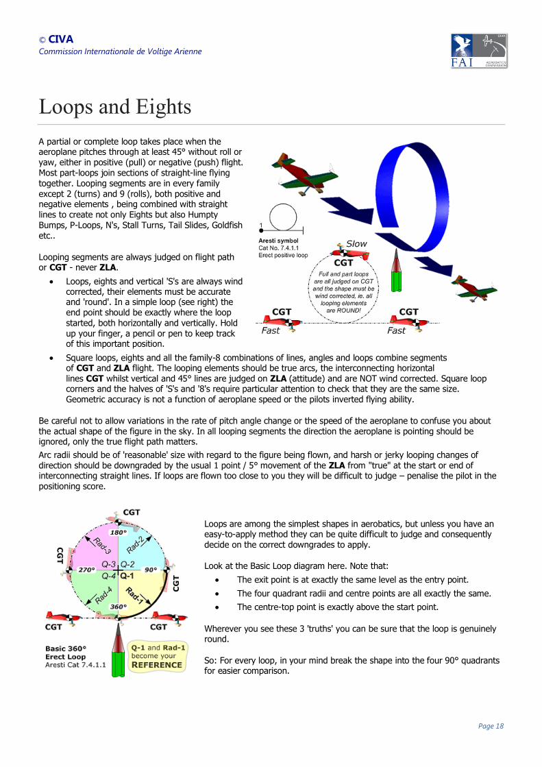
A partial or complete loop takes place when the aeroplane pitches through at least 45° without roll or yaw, either in positive (pull) or negative (push) flight. Most part-loops join sections of straight-line flying together. Looping segments are in every family except 2 (turns) and 9 (rolls), both positive and negative elements , being combined with straight lines to create not only Eights but also Humpty Bumps, P-Loops, N's, Stall Turns, Tail Slides, Goldfish etc..
Looping segments are always judged on flight path or CGT - never ZLA.
Loops, eights and vertical 'S's are always wind corrected, their elements must be accurate and 'round'. In a simple loop (see right) the end point should be exactly where the loop started, both horizontally and vertically. Hold up your finger, a pencil or pen to keep track of this important position.
Square loops, eights and all the family-8 combinations of lines, angles and loops combine segments of CGT and ZLA flight. The looping elements should be true arcs, the interconnecting horizontal lines CGT whilst vertical and 45° lines are judged on ZLA (attitude) and are NOT wind corrected. Square loop corners and the halves of 'S's and '8's require particular attention to check that they are the same size. Geometric accuracy is not a function of aeroplane speed or the pilots inverted flying ability.
Be careful not to allow variations in the rate of pitch angle change or the speed of the aeroplane to confuse you about the actual shape of the figure in the sky. In all looping segments the direction the aeroplane is pointing should be ignored, only the true flight path matters.
Arc radii should be of 'reasonable' size with regard to the figure being flown, and harsh or jerky looping changes of direction should be downgraded by the usual 1 point / 5° movement of the ZLA from "true" at the start or end of interconnecting straight lines. If loops are flown too close to you they will be difficult to judge – penalise the pilot in the positioning score.
Loops are among the simplest shapes in aerobatics, but unless you have an easy-to-apply method they can be quite difficult to judge and consequently decide on the correct downgrades to apply.
Look at the Basic Loop diagram here. Note that:
The exit point is at exactly the same level as the entry point.
The four quadrant radii and centre points are all exactly the same.
The centre-top point is exactly above the start point.
Wherever you see these 3 'truths' you can be sure that the loop is genuinely round.
So: For every loop, in your mind break the shape into the four 90° quadrants for easier comparison.

© CIVA
Commission Internationale de Voltige Arienne
Page 19
Put a pencil or pen up against the start point, and use this point and the 1st quarter loop as your reference. Now you can describe the remaining quarters, particularly their radii and end points, by comparing them with the first quadrant and the location of the original start point. Note also the angle that each quadrant describes about the centre of the first arc, which should always be 90°. If it's well flown and the shape looks like the one above, then it's probably worth a ten. Here are some classic errors in the sketches on the right:
1. The 1st half is fine, then the radius gets smaller at the top. The 2nd half is tighter, and the exit significantly higher than the entry.
2. The 1st half again is fine but the top is flattened with increased radius. The 2nd half is larger than the first, and the exit is significantly lower than the entry.
3. This one has a definite "Lazy Sunday afternoon" style - possibly with the same stick position until the end.... then a big pull. The 1st half radius tightens towards the top as the aeroplane floats at below stall speed inverted, then in the 2nd half it falls freely until increasing airspeed gives the elevator some bite and 'down-rush' anxiety tightens the radius again to a low exit. Not good!
4. In this half-loop the 2nd quadrant radius is tighter than the 1st, leading to a smaller 2nd half and early exit not over the entry point.
5. Here is the opposite fault, where the 2nd quadrant has been forced to a larger radius to 'float' the top and avoid (4) - making the exit too high and once again not above the entry point.
6. In eights it is also necessary to judge the relative size of both the looping elements. Use the pencil to 'fix' the start as usual, then with a finger or by reference to some local cloud feature make a judgement about the size of the 2nd loop and the exit trajectory.
Downgrades
As you watch the figure, for every radius variation, missed angle point, entry and exit height mis-match you see, simply accumulate the penalties below and subtract them from 10 to reach the final figure score:
Arc radii A small but noticeable variation: -1 point
A more significant but not serious variation: -2 points
A large variation significantly changing the figure shape: -3 to -4 points
Missed angle Where the 'top point' is < or > 180° from the bottom point: -1 point per 5°
Height mis-match A small but noticeable error: -1 point
A more significant but not major error: -2 points
A large error that significantly changes the figure shape: -3 to -4 points

© CIVA
Commission Internationale de Voltige Arienne
Page 20
Half-Loops with Rolls
When a half-loop upwards or downwards has some rolling at the start or end of the looping segment, there must be NO horizontal line between the rolls and the looping arc.
Occasionally a pilot will 'forget' the roll(s) that must be flown or simply insert a short pause to collect his/her thoughts, and the length of the horizontal line that is flown becomes very obvious. These 'inserted' lines must be penalised as
shown in this graphic.
You should always memorise the size of looping arcs as they are being flown, and if the required rolling manoeuvre does not immediately precede or follow the arc - i.e. with NO horizontal line at all - then you can compare the length of the line that you see to the radius
of the half-loop.
Where no line is drawn there is no downgrade to apply.
If you see any line at all then at least a one point downgrade must be applied.
As the length of this unwanted line increases but remains less than the half-loop radius, two to three points should be deducted.
If the length of the line exceeds the half-loop radius you must award a PZ (Perception Zero) for the figure.
Loops and Part Loops
Judges must assess the shape and smoothness of all looping segments in order to arrive at a possible downgrade.
Definition
The loop is a figure from Family 7, but part-loops are integral to every other family so it is necessary to discuss the loop before going on to the other families.
By definition a loop must have a constant radius. It starts and ends in a well-defined line which, for a complete loop, will be horizontal. For a part-loop however, such lines may be in any other plane of flight and will be defined by the aircraft's attitude. As the speed changes during execution of a loop or part-loop, the angular velocity around the aircraft's lateral axis also has to change in order to keep the radius constant. When the speed decreases, for example, to half its initial rate, the angular velocity, to keep the same radius, will be reduced by half - this is a fact of physics. Thus, the angular velocity can be an aid for the Judge to gauge the radius, especially when the angular velocity in the higher part-loop is seen to be faster, as this is a clear indication that the radius is smaller. This aid becomes more important when two part-loops are separated by a line between.

© CIVA
Commission Internationale de Voltige Arienne
Page 21
Aresti pictogram shapes
In the Aresti Aerobatic Catalogue, part-loops are depicted either as round elements or as ‘corner’ angles. It must be noted that any ‘corner’ angle drawn in the pictograms is always to be flown as a part-loop and must have a smooth, distinct and constant radius.
Judging ‘sharp corners’ and ‘round corners’ in part-loops
Sharp Corners
For any one figure having more than one internal part-loop depicted in the catalogue as corner angles, all such part-loops may have different radii, and none of them is required to match the radius of any part-loop depicted as a round element in the same figure – with the exception of:
Family 3 (combinations of lines) and –
Family 3 : 7.4.3.x to 7.4.6.x (whole / hesitation loops)
These figures must all keep a regular geometrical shape, and therefore their part-loops are all required to have the same radius. Note that the above guide only shows some of the affected figures - the principle however is
general.
Round Corners
For any one figure having more than one internal part-loop depicted in the catalogue as round elements, all such part-loops shall have the same radius – with exception for all of Family 8.8 figures (double humpty bumps) for which the radius of the second half-loop is not required to match the radius of the first one.

© CIVA
Commission Internationale de Voltige Arienne
Page 22
The Stall Turn
The Stall Turn is one of the most graceful aerobatic figures. When flown well it is beautiful to watch. The figure can be divided into a series of sections for judging:
The entry and pull to vertical
Is the entry from truly level flight?
Part-loops must have constant radii.
Is the vertical hit correctly?
Is the aeroplane on axis at all times?
The vertical up line
Does the line stay vertical?
Does the aeroplane stay on axis?
It is common for the aeroplane to roll on the up-line, especially towards the top
The turn itself
Is the centre of the turn within one wing? Bridging must be downgraded.
Is the turn in the correct plane?
Is the aeroplane rolling at all during the turn (torque'ing)?
What is not judged
The rate of the turn - slow or fast.
The lengths of the up and down lines.
Practical Tips
Look carefully to see if the aeroplane is vertical before and after the turn.
Check that the wing trailing edges are parallel to the horizon when in the vertical - ie. no yaw or wing-low.
Check that the aeroplane does not fall back in pitch before the turn.
Look for roll corrections after the turn has been completed.
Check that the part-loops are all smooth and of constant radius.

© CIVA
Commission Internationale de Voltige Arienne
Page 23
More thoughts on Stall Turns …
The up and down-lines must be ZLA vertical. Any slow or flick rolls on them must however be judged on their flight path / CGT.
In the turn-round you should see yaw without any pitch or roll. Sideways movement of the aeroplane (called ‘bridging’) of up to one wingspan during the 180° rotation is acceptable, but any more than that must be penalised: the downgrade is 1 point per ½ wingspan, or beyond 2 wingspans the penalty is a ‘Hard’ zero.
The part-loop radii may be of different sizes, but must have constant radius.
Be critical about the verticality of the aircraft ZLA in the up-line all the way to the top.
Any pitch or roll in the turn-round is a clear error - 1 mark lost per 5° as usual.
In a stall-turn with rolling elements up or down there may be several changes from CGT to ZLA judgement and vice-versa.
If the exit is on the "A" axis check that the direction is correct, and in erect or inverted flight as is required by the sequence.
Downgrades
Entry and exit radii must be smooth and of constant radius or an appropriate downgrade given, the usual 1 point / 5° applies in pitch for the up and down lines and also within any roll that is detected in the turn, and the turn itself must pivot within the silhouette of one wing or 'bridging' must be penalised as above.

© CIVA
Commission Internationale de Voltige Arienne
Page 24
Tail Slides
The first two comments from the stall turn section apply equally here regarding the pull or push to the vertical line, accurate maintenance of the line, and the eventual pull or push at the foot of the figure.
When the aeroplane reaches the top of the vertical line it will stop for an instant, then begin to slide back downwards. The slide should descend straight back at least half the length of the fuselage without any pitch change before the swing-through starts, or a Perception Zero must be given. In the slide there must be no rotation in the rolling or yawing planes, the wings must remain parallel to the horizon and at right angles to the original entry direction.
The nose must 'fall through' in the correct direction: either wheels DOWN / canopy UP (the falling element in the Aresti diagram will have a full line) or wheels UP / canopy DOWN (drawn with a dotted line in red as shown in the sketch here).
Pendulum effect, that is when the nose swings one or more times through the vertical after the initial slide and fall through, doesn't matter. Judgement of the vertical down line begins as soon as this pendulum effect has stopped.
Check the rearwards slide for length and straightness - you'll need a raised finger or pencil to do this accurately. Also look carefully to see that the aeroplane doesn't roll and yaw as the nose falls through, or gauge the amount if it does.
In the diagram:
Radius 'A' and radius 'D' must be constant
Length 'B' = length 'C'
Height difference 'E' is not important
Downgrades
The entry and exit radii must be constant just like a Stall Turn, the usual 1 point / 5° applies in pitch, roll and yaw for the up line - particularly at the 'stop', in the slide, and for the down-line, and throughout the pendulum period the yaw/roll attitude must be straight or it must be penalised in the same way.
If you consider that a tail slide does not meet the half-fuselage length rearwards slide criterion then you should give a Perception Zero and not a Hard Zero. Line lengths before and after up or down vertical rolls are judged with the usual 1 point downgrade for a visible variation, 2 for a 2:1 variation etc..

© CIVA
Commission Internationale de Voltige Arienne
Page 25
Humpty Bumps
Humpty Bumps are simple family-8 figures to which a wide range of complementary rolls (including spins) may be added to create a great diversity of results.
The variations can go upwards or downwards from the start point, and be either vertical or skewed to commence with a 45° or 135° pull or push from horizontal flight. The turn-around is always a half positive or negative loop to reverse the aeroplane in pitch through 180° back towards the start point.
The same entry and exit radius and line rules apply as for a stall turn, the pull or push half-loop must also be of (not necessarily similar) constant radius, and the heading must be accurately maintained throughout. In the main example here a 45° skewed Humpty has a two-point half roll on the up-line and a half positive flick roll on the down-line. The inset shows a 'plain' all-positive erect vertical humpty without added rolls.
In the diagram
Radius 'A', 'E' and 'D' must be constant, but need not be the same
Length 'B' = length 'C'
Height difference 'F' is not important.
Downgrades
The entry and exit radii and the radius for the half-loop can be all of different sizes, but they must be smooth arcs - a tightening or widening of the radius after the initial pull or push should attract the usual 1 (minor), 2 (more noticeable) or 3 (severe) points downgrade. The standard 1 point / 5° error applies for the two major lines, and during and after the turn-around where slow speed and high torque in up-going humpties can lead to significant heading variations and part-stalls.
Line lengths before and after up or down rolls are judged with the usual 1 point downgrade for a visible variation, 2 for a 2:1 variation etc.. Where a spin is imposed on the down-line of an 'inverted' Humpty it will of course be at the top of the line, and any subsequent roll before the pull or push turn-around executed after a brief pause - note that this second roll should NOT be centred in the remaining line, which would be an error.

© CIVA
Commission Internationale de Voltige Arienne
Page 26
The Direction of Flight
The main rules to remember are -
Figures that are drawn with the sequence starting and finishing on the 'main axis' of the box must be flown either into or away from the official wind, in accordance with the wind arrow on the Form-B/C sequence drawing.
Figures that start on the main axis and finish on the secondary axis, or vice-versa, must be flown with the main axis section towards or away from the official wind in accordance with the wind arrow, but the secondary or cross-axis section may be flown towards or away from the judges - in other words, the direction of the cross-axis flight is at the discretion of the pilot, who may turn from axis-A to axis-B to the left or right in order to position the aeroplane to the best advantage under the circumstances. Such decisions usually reflect the influence that the wind is having on sequence positioning.
Some figures that start and finish on the secondary axis but which have elements within them that are flown temporarily along the main-axis must follow these restrictions: Family 1 and 8 figures must be flown in strictly as they are shown on the form-B/C relation to the official wind.
Thus the central element in the above example figures 1 and 3 must be flown into wind, that in figures 2 and 4 must be downwind, or you should regard them as ‘wrongly flown’ and award an HZ. Cross-box to cross-box 180° and 360° turns and rolling turns however are exempted from this obligation, the L/R direction of the turn being at the pilots’ discretion.
Stall turns and tail slides are also unaffected by the above, the orientation of the aeroplane at the top being entirely dictated by other natural choices or constraints.
If the pilot takes a 'break' or interruption on the secondary axis then:
If the break is taken following a correctly flown figure then the restart direction must be the same as that before the break was taken - if the restart is made in the opposite direction then every ensuing cross-box figure must receive a hard zero (flight in the wrong direction) until the error is rectified or flight along the main axis is resumed.
After a penalized interruption, there is no obligation for the pilot to resume the sequence in a direction determined by the flight before the interruption.
You must therefore maintain a constant awareness of the 'correct' or 'allowable' direction of flight of and within each figure, and make sure to apply the relevant penalty should any of the above rules not be met.

© CIVA
Commission Internationale de Voltige Arienne
Page 27
Wing rocks - The sequence beginning and end, and 'breaks'
Power pilots are required to rock their wings three times to indicate to the Judges the beginning and end of their sequence, and again for any 'breaks' to regain altitude or re-position the aircraft after mistakes during the sequence. For glider pilots there are no wing rocking requirements for 'breaks', a simple resumption of the correct flight path being acceptable so that the flight can continue with the minumum energy loss. Failure to wing rock where required carries its own specific penalty - ask the Chief Judge if in doubt. The sequence starts as soon as the aircraft reaches straight and level flight (erect or inverted) after the
third wing rock. Be prepared – judging begins at that point .... !
There are few strict rules regarding the way that the wing-rocks are to be flown except that they must be clear to the judges and the roll angles should exceed 45°. They need not be flown inside the performance zone or box, but if they are missed altogether then not only will the judges be confused but a fixed penalty will be applied. If the pilot flies the allowed training figures they must be flown in the approved style inside the box before the wing rocks, or you should record a training violation on the marks sheet. There can be no downgrades for wing rocks however as they are not a
'scored' figure.
If the sequence starts with a high-level slow entry figure such as a spin the pilot may place the wing rocks on a climbing line, even up to vertical, to position the aeroplane at the desired altitude and location at slow speed instead of with high energy. If the wing rocks are executed partly or wholly on a vertical line the exit may be
either a 'push' to erect or a 'pull' to inverted.
Mid-sequence breaks taken by pilots at Intermediate and above incur fixed penalties, but these are not awarded to Club
and Sports pilots.
Where a sequence is re-started after a mid-sequence break with the next figure on the "B" or cross box axis, the direction of flight must be the same as it was before the break or the following figures will receive hard zeros (HZ) until the 'A' axis is resumed.

© CIVA
Commission Internationale de Voltige Arienne
Page 28
Preparing for the mental
arithmetic, and making your comments
Prepare for each flight by reading right through the sequence sheet to visualise the key points to look for. During the sequence you will then find it much easier to complete the arithmetic for each figure.
Experienced Judges have all sorts of different ways of remembering the errors to arrive at the 'right' mark for each figure, preferably at the time but occasionally after the sequence has ended.
Here's a good method
Say out loud to yourself and your assistant what you see - good and bad - as it happens. This will help you to identify the errors you saw the pilot make, and your assistant can easily record a sensible critique for the pilot. Say clearly how many degrees you think that the aircraft is pitched, (positively or negatively), rolled or yawed (left or right) in 5° steps, and by what proportion you think that the line-lengths are too short or too long - before or after other key elements. Whilst you are doing this, count on your fingers the accumulated marks to deduct from each figure. All you have to do then is take away your running 'digital' total from ten - and you have the final score for each figure.
There are two very good things about this particular technique. Not only will you soon be weighing the pro's and con's of the errors you see, but it is tailor-made for your assistant to keep a good audit trail of the flight in the comments column. This is important both for the pilot and for you later on.
Sometimes it all happens so quickly that you simply can't make up your mind in time, so just leave grading that figure until the end of the sequence and then you can back track, re-read your comments and re-compose your answer, or if all else fails you'll have to confess to a 'don't know'. If this happens, get your assistant to mark it as "Not Seen" in the comments column and put an ‘A’ instead of the score, then the computer will convert this to an average of everyone else's scores. All the best Judges do this sometimes, so don't worry! The sequence ends with a further three wing rocks, at which point you must consider the framing mark.

© CIVA
Commission Internationale de Voltige Arienne
Page 29
The Positioning or Framing Mark The positioning mark is a measure of how well the pilot manages to fly the sequence with each figure located at an "ideal" position within the overall presentation. These rules changed in 2012. As each figure is being flown, compare it's actual location in the box with where in your view it would be ideally positioned. If the location fits well with the preceding and following figures and you are comfortably able to judge each element of it, then you can accept that the position is OK.
However - if the figure is sufficiently near, far, or to the left or right that the presentation and/or the judging becomes compromised then some downgrading will be appropriate, and you should record your observations like this:
If the figure is somewhat too near to you, after you give the mark for the figure add the word "Near". Your scribe should write the letter 'N' in the comments column of the marks form to represent your comment
If it is somewhat too far away then add the word "Far"; your scribe will write 'F'
For figures somewhat too far to the left or too far to the right, add the word "Left" or "Right", to be written as 'L' or 'R'
If the figure is located much too far to the left, right, near or far then add the appropriate word twice. For instance "Near near" or "Right right" should be recorded as 'NN' or 'RR'. A figure that is flown in the distant left rear corner of the box might thus be described as "Far far left", written as 'FFL'
To calculate the Positioning Mark
First: To reach a conclusion for the Left-Right-Near-Far positioning of all the figures, review the 'L', 'R', 'N' and 'F' annotations and for each letter deduct a ½ mark from 10.0.
Then: To account for symmetry, look through just the 'L' and 'R' letters again, and if there are more 'L's than 'R's (or vice-versa) then deduct a further ½ mark for each un-paired letter.
Example: For a sequence where you record L, N, FL, FF, R and N again, your mark would be 10.0 minus (8 times a ½ = 4.0) and then minus another ½ because you have 2 'L's and only one 'R'. The answer in this case would thus be 5.5 for the overall Positioning Mark.
Learn to do this consistently ... and your framing marks will be consistent!
Note 1: Figures that are flown too far away to be reliably judged must receive a downgrade of 2-points for each element that you can't judge - this is subtracted from the mark for the figure, separately from any "Far" comments about the positioning.
Note 2: Figures that start behind the judging line should in any case already receive a mark of zero as well as being annotated 'NN' for position.
The ‘Harmony’ mark is now abandoned – it is not used from 2017 onwards.
© CIVA
Commission Internationale de Voltige Arienne
Page 30
Major Errors
The rules on the three sorts of zero marks are as follows
Ten or more downgrades simply leads to a mark of ZERO (0.0)
In this case the pilot flies the expected Aresti figure but the judge sees total of 10 or more downgrades, and consequently all marks for the figure are lost. In other words there are so many errors that the judge simply runs out of marks. This is a plain 'zero' and is written on the Form-A as 0.0 - but not "ZERO"! A 0.0 is as valid a mark as 8.5 or 3.5.
Errors of demonstrable fact are marked Hard Zero (HZ)
Here the figure flown is the wrong one (in other words, not as drawn on the Form B/C). A figure might have been flown very smoothly, but if it is not the required figure then the score is Hard Zero (HZ). This includes flying the 'right figure' in the wrong direction, on the A or B axis. If video replay is available you will be able to see and prove that a factual error (a HZ) was made ... or not.
Errors of subjective perception are marked Perception Zero (PZ)
If a pilot flies the right figure but a judge perceives that what he has seen does not meet a required perception criterion, then a PZ should be given. Perception zeros apply to flick (snap) rolls, spins, tail-slides, and for gliders also to stalls in loops and turns. In each case the criterion that must be satisfied will be a fleeting 'judgement' or perception rather than a clearly judgeable error, and the video cannot subsequently be used to prove or disprove it.
For judges the 'Perception Zero' has another key quality: if a PZ fails to pass the FairPlay confidence test when the scoring software is run - usually when a majority of the other judges award that figure a non-zero mark instead - it is simply replaced by a more appropriate or 'fitted' value, and this substitution means that a PZ that fails to be upheld does not affect the judges' RI (Ranking Index). Judges are thus free to express their 'perception opinions' without fear that this may affect their standings in the international judge ranking systems.
When would a 0.0 or a PZ be changed to a Hard Zero?
Consider zeros that arise from many downgrades: when using the 1 mark per 5° deduction, if any single angular error exceeds 45° then the mark must be 0.0. However if a single angular error exceeds 90° then the mark must be a Hard Zero; in most cases when an error of more than 90° occurs the figure actually flown will be a different but valid Aresti figure, and it should be marked as a Hard Zero for that reason. There will still be cases where there is disagreement between judges as to whether a full 90° error occurred or whether it was the correct figure badly flown or an incorrect figure. In this situation the Chief Judge will decide which type of zero will apply - although it will make no difference to the Pilots score.
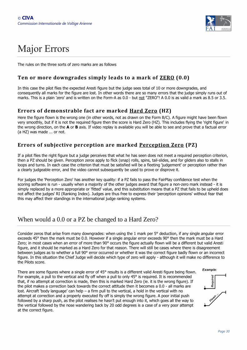
There are some figures where a single error of 45° results is a different valid Aresti figure being flown. For example, a pull to the vertical and fly off when a pull to only 45° is required. It is recommended that, if no attempt at correction is made, then this is marked Hard Zero (ie. it is the wrong figure). If the pilot makes a correction back towards the correct attitude then it becomes a 0.0 - all marks are lost. Aircraft ‘body language’ can help – a firm pull to the vertical, a hold in the vertical with no attempt at correction and a properly executed fly off is simply the wrong figure. A poor initial push followed by a sharp push, as the pilot realises he hasn’t put enough into it, which goes all the way to the vertical followed by the nose wandering back by 20 odd degrees is a case of a very poor attempt at the correct figure.

© CIVA
Commission Internationale de Voltige Arienne
Page 31
Hard Zeros … you and the Chief Judge
Every Judge must decide for each figure whether it should be marked normally (a mark from 10.0 down to 0.0, or a PZ) or given a Hard Zero. Where one or more Judges give a Hard Zero for a figure the Chief Judge must decide whether the Hard Zero should be given for all judges, or for none - it must be one or the other. If video is available it can be used to help make the decision. This decision is recorded on the Flight Summary Sheet, which provides the scorer with key information about each figure in the flight.
When the pilots marks are processed by the "FairPlay" system, special attention is given to any figures that are awarded a Hard Zero mark by one or more judges. The outcome depends on whether the figure has been declared as "OK" (ie. not a HZ) or as "CHZ" (a Confirmed Hard Zero) on the Flight Summary Sheet.
Where the figure is declared on the Flight Summary Sheet as "OK" then it follows that any Judge who has given a HZ is in effect wrong. FairPlay will replace the Judge's HZ with a 'Fitted Mark'.
Where the figure is declared on the Flight Summary Sheet as "CHZ" (a Confirmed Hard Zero) then any Judge who has given a PZ or 0.5 to 10.0 mark is similarly wrong, and a 'Fitted Mark' will be substituted.
This clear separation of OK / markable figures from Hard Zero / non-markable figures is a key part of the FairPlay system - the "was it?" / "wasn't it?" question must be resolved by all Judges long before the scorer enters the Pilots marks. Inevitably some judges will miss errors or think they see an error where there really wasn't one, and some will not. Errors such as rolls being the 'Same direction' and not 'Opposite' or perhaps a missed hesitation can give rise to un-resolvable arguments - and the figure itself is by then long since gone. If this happens the Chief Judge must discuss it with all the Judges and decide whether the mark should survive (OK) or be declared a CHZ, and that becomes the final decision for for the figure.
So - if you think that you see the 'wrong' figure flown then follow your instinct and give it a Hard Zero, and your scribe should record the reason. However be very careful to stick to the mark 'zero' (yes - it is a score!) where you simply run out of fingers during the deductions. This zero mark is written as '0.0' on the score sheet to emphasize you mean a numeric zero rather than a Hard Zero, for which you would write 'HZ'.
Don’t worry about having a Hard Zero 'overturned' by the Chief Judge, you may be the one that got it right (but this time the pilot got away with it . . .). Every judge has heard a pilot admit (usually long after the event) that they saw a real mistake and the other judges got it wrong. The judgement of aerobatic figures is a complex game played between expert Pilots and expert Judges - need we say more?
Remember that whilst you should always give the pilot the benefit of the doubt if you are unsure, it is still up to the pilot to show you the expected figure. If, in your opinion, the Pilot fails to do that then you must give your mark accordingly. The four most common major errors which must get an 'HZ' are:
Incorrect rolls (Same not Opposite, In not Out, 2 point not 4 point etc.).
Missing out part of a figure.
Missing out a whole figure, and
Flying in the wrong direction on the "A" axis (or doing "A" axis figures on the "B" axis!).
Where a figure is badly flown but still generally as specified on the sequence diagram, the usual deduction of 1 mark per 5° of error is all that is necessary. Where a mistake leads to a pilot flying cross-box instead of on the "A" axis (or vice-versa) or in the wrong direction on the "A" axis however, all figures get a hard zero until and unless the unfortunate pilot resolves the problem, as they will all start with a 90° or 180° direction error. In such cases, if you can, you should continue with your comments and put the marks the pilot would have got in brackets - then he still benefits by seeing what he threw away.

© CIVA
Commission Internationale de Voltige Arienne
Page 32
Judging Downgrades Summary
Here is a précis of the principal "faults" that you should look for and the number of marks to deduct whilst you are applying standard CIVA rules of critique to sequence programmes at all levels. Always however refer to the current CIVA Section-6 Rules (power or glider) for the ‘official’ solution in all matters of judging detail.
At the entry to and exit from EVERY figure element
Horizontal start & finish Lines Downgrades
Off axis left or right ‘n’ degrees 1 point / 5 degrees
Climbing or diving ’n’ degrees 1 point / 5 degrees
One wing low ‘n’ degrees 1 point / 5 degrees
No distinct line drawn 1 point each
Flying in wrong direction on the "A" axis Mark = Hard Zero (HZ)
Family 1 - lines and angles
Horizontal 45's & Verticals
Climbing or diving ‘n’ degrees (before or after roll) 1 point / 5 degrees
Steep or shallow ‘n’ degrees (before or after roll) 1 point / 5 degrees
Positive or negative ‘n’ degrees (before or after roll) 1 point / 5 degrees
No line drawn before or after roll 1 point each
Longer or shorter line before or after roll 1 to 3 points
Family 2 - turns and rolling turns
Turns
Rolling entry or exit (i.e. a "co-ordinated" turn) 1 to 2 points
Bank angle too shallow (less than 60 degrees) 1 point / 5 degrees
Bank angle varied 1 point / variation
Rolling Turns
Roll rate varied 1 point / variation
Roll stopped or turn and then restarted 2 points
Not an even integration of rolls at end 1 point / 5 degrees
Not enough / too many rolls or a flick-roll seen Mark = hard zero

© CIVA
Commission Internationale de Voltige Arienne
Page 33
Turn rate or radius varied 1 point / variation
Climbing or diving in turn 1 point / 5 degrees
Exit
Was ‘n’ degrees early or late 1 point / 5 degrees
Family 3 - combinations of lines
All Figures
Longer or shorter 2'nd etc. line 1 to 3 points
Family 5 - stall turns
Up/Down Lines
Up / down-line positive / negative / left / right ‘n’ degrees (before or after roll) 1 point / 5 degrees
Short, long or no line drawn up/down (before or after roll) 1 to 3 points
The Turn
Turn-around too wide (pivot beyond wingtip) 1 point / wing length
Rolled or pitched ‘n’ degrees in turn-around 1 point / 5 degrees
Exit pull or push radius smaller or larger 1 to 3 points
Family 6 - Tail Slides
Up/Down Lines
Up / down-line positive / negative / left / right ‘n’ degrees (before or after roll) 1 point / 5 degrees
Short, long or no line drawn up / down (before or after roll) 1-3 points
The Slide
Visible 'cheat' angle at the top 1 point / 5 degrees
No slide seen Mark = Perception Zero (PZ)
Yawed or rolled ‘n’ degrees in slide 1 to 3 points
Pitched the wrong way (wheels up or down) Mark = Hard Zero (HZ)
Family 7 - Loops and Eights
Half & Full Loops
Large or small radius at top or in 1'st / 2'nd etc. quarter 1 to 3 points

© CIVA
Commission Internationale de Voltige Arienne
Page 34
Line drawn between roll and looping segment 1-3 points, PZ when line > radius
Roll not central in looping segment 1 to 3 points
Off axis during looping segment 1 point / 5 degrees
Higher or lower exit 1 to 3 points
Eights
Smaller or larger 2'nd half 1 to 3 points
Lower or higher 2'nd half (horizontal) 1 to 3 points
With corners
Longer or shorter 2'nd etc. line length 1 to 3 points
Up/down-line positive/negative/left/right ‘n’ degrees {before or after roll} 1 point / 5 degrees
1'st/2'nd etc. 45 steep or shallow {before or after roll} 1 point / 5 degrees
Horizontal segment off axis left / right / up / down 1 point / 5 degrees
Family 8 - Combinations of Lines, Angles and Loops
Humpty Bumps
Up / down-line positive / negative / left / right ‘n’ degrees (before or after roll) 1 point / 5 degrees
Rolled or yawed in half-loop 1 point / 5 degrees
Push instead of pull, or pull instead of push Mark = hard zero
Family 9 - Rolls and Spins
Slow Rolls
Rolled n-degrees short or too far 1 point / 5 degrees
Roll barrelled (pitched and/or yawed whilst rolling) 1 point / 5 degrees
Roll rate varied 1 point / variation
Axis changed left/right/up/down ‘n’ degrees during / after roll 1 point / 5degrees
Hesitation at random point 2 points
Wrong type of roll substituted Mark = Hard Zero (HZ)
Hesitation Rolls
Climbed or sank in knife 1 to 2 points

© CIVA
Commission Internationale de Voltige Arienne
Page 35
Slower or faster 2'nd etc. half/quarter/eighth 1 to 3 points
Under/over rotated 1'st/2'nd etc. half / quarter / eighth 1 point / 5 degrees
Hesitation missed (wrong type of roll substituted) Mark = Hard Zero (HZ)
Flick Rolls
Part flicked and part aileron'd roll 2 to 5 points
Not flicked (no stall seen) Mark = Perception Zero (PZ)
Positive instead of negative, or negative instead of positive Mark = Hard Zero (HZ)
Combinations Of Rolls
Any line between two rolls At least 2 points
Significant(?) line between rolls Mark = Hard Zero (HZ)
Same direction when opposite required (or vice versa) Mark = Hard Zero (HZ)
Wrong number of rolls where linked Mark = Hard Zero (HZ)
Rolls immediately prior to or just after looping
Any line between stopping loop / roll and starting roll / loop 1-3 points, PZ when line > radius
Roll starts before loop finishes 1 point / 5 degrees (from line)
Significant line between rolls Mark = Hard Zero (HZ)
Spin Entry
Entry not stalled, and / or "rolled" in – not spinning Mark = Perception Zero (PZ)
Flicked entry (too fast) Mark = Perception Zero (PZ)
Spin Exit
Spin rotation short or too far ‘n’ degrees 1 point / 5 degrees
Line after was positive or negative ‘n’ degrees 1 point / 5 degrees
No line drawn after Mark = Hard Zero (HZ)

© CIVA
Commission Internationale de Voltige Arienne
Page 36
The following general points apply to all sequences:
At unlimited and advanced levels two half-rolls and a selection of “safety figures” are allowed prior to the start of the sequence, as shown below. At other levels reduced allowances are made - consult the respective national rules.
The sequence start, end and any intermediate breaks must be signified by three wing rocks.
Every figure must begin and end on the "A" or "B" axis in erect or inverted level flight.
The mark for each figure is 10 points minus the sum of the deductions that you judge appropriate.
Figures missed-out, obstructed by cloud or started behind the Judges must be awarded a hard zero.
For a figure flown so far distant that the exact detail is not apparent, the maximum mark should be 5.0
The framing mark (out of 10) is judged on the symmetrical and good use of the whole 'box'.
Zeros
Occasionally the Chief Judge will call the Judging panel members together after a sequence to discuss contentious points. Debates at these occasions can become quite heated, but a common settlement of any disputed points is essential and it is the Chief Judge's job to ensure that this is reached as quickly as possible. Whilst you should certainly present your own point of view, once the Chief Judge has made a decision - do accept it! It in unfair to harass the CJ and impossible to prove who is actually correct.
© CIVA
Commission Internationale de Voltige Arienne
Page 37
Some plain common sense!
Do...
Plan the day carefully, the benefits are considerable. For instance:
Bring a pad to write on, a couple of pens, a little set-square, your reference notes, sun-glasses, a folding chair, some suntan oil and a warm coat, gloves and hat. Except on the warmest of British summer days, judging tends to be a cold business – come prepared.
Re-read the books .... everybody forgets some of it from time to time, why should you be different? Occasionally the rules change too, just to keep you on your toes.
Bring an assistant if possible and share the enjoyment with a friend. Their main qualification is to be able to write quickly and legibly. You never know what you might be starting!
Get to the contest on time. A late arrival is no good to anyone.
Sit at a good distance from other judges so that you cannot easily hear what others are saying – it only distracts and it is your own opinion of what you saw that counts.
Put your Judge's number and your name on every Judging Sheet - this is VERY important to the computer operator, who must get your results into the computer in your slot every time.
Ask questions about anything in doubt! Your Chief Judge will respect you for asking and will be able to offer a wealth of experience and comment. If you don't ask you may never know.
Keep the comments flowing during the figures, and impress your assistant with the importance of writing them down. These gems are life itself to pilots - a silent Judge is no help at all.
Be a nit-picker - it's your job! But be positive too - if you think that the figure you just saw was flown completely without error then you owe it to the pilot to GIVE IT A TEN.
Talk to the pilots - and the less fortunate non-aerobatic ones back at your local club - about how the judging process works. Sometimes even competitors are less well informed than you might think. Exactly where and why marks are lost is your stock in trade, so spread the word.
Enjoy yourself! We all know that judging is quite hard work, but the rewards are there for the taking. How else could you get involved in so much aerobatic flying for next to nothing?
Don't...
Judge "emotionally" - by this we mean don't let the figure happen and then just give it an overall guessed mark based on jumbled thoughts. 1 - Look for the actual errors, 2 - add up the appropriate deductions, and 3 - give an honest opinion. Anything else is passing the buck.
Wait until you can hear the other Judges give their marks and then make up a similar one to be "in line" with the rest. It takes time to develop your own style so that you can get to the right mark on your own, but it will take you longer still if you borrow your colleagues’ material. Be assertive and believe in yourself - it's important. Why should they be right and you wrong?
Be persuaded that your interpretation of the pilots’ execution of a figure is wrong unless it can be explained to you so you believe it. If you think you saw some errors, stick to your guns.
Mark a figure down to less than ten simply because although you didn't see anything wrong with it the pilot hasn't been that good so far. If it was well flown and you saw nothing out of order then GIVE IT A TEN - the pilot deserves it. Conversely - if you are sure that you see a well-respected pilot make some mistakes then it is your clear duty to deduct all the appropriate marks and tell him why. Beware of 'halo effect' from the heroes - they're just pilots too!
If you're flying as well as judging, don't try to judge and then go flying (or vice-versa) without a natural break - your performance and safety will suffer, and it just isn't worth it.
Allow pilots to sit around the judging line and listen-in to your pearls of wisdom - especially if they're from the same level you are judging. Whilst you are "doing the business" you need total concentration and solitude, so just ask them to leave. They will. You're in charge.

© CIVA
Commission Internationale de Voltige Arienne
Page 38
Useful Reference Material
International documents
There are TWO different Aresti Catalogues, one for Power and the other for Glider aircraft –
1. Aresti (condensed) Catalogue – Power http://www.arestisystem.com/ Shows all aerobatic figures and part figures that can be used in Aresti based sequences for power aircraft, together with the difficulty factor for each figure or part figure.
2. Aresti (condensed) Catalogue – Glider http://www.arestisystem.com/ Shows all aerobatic figures and part figures that can be used in Aresti based sequences for glider aerobatics, together with the difficulty factor for each figure or part figure.
CIVA Regulations for the Conduct of International Aerobatic Events
http://www.civa-news.com/civa-document-store or
http://www.fai.org/civa-documents
Part One: Events for Powered Aircraft Part Two: Events for Glider Aircraft
FAI Sporting Code - Section 6 http://www.civa-news.com/civa-document-store
http://www.fai.org/civa-documents
General and Judging Rules for World and Continental Aerobatic Championships and International Aerobatic Competitions (Powered Aircraft and Gliders). This is a specific Sporting Code for aerobatics and describes how an international contest should be administered.
Useful Website Addresses:
FAI: www.fai.org
CIVA: www.civa-news.com and www.fai.org/aerobatics
Aresti6: www.freestyleaviation.co.uk
OpenAero: www.openaero.net
ACRO: www.exploit-design.com/AeroSoftware/ACRO-software.htm
Aresti Systems S.L: www.arestisystem.com
Nick Buckenham
© CIVA Judging Tutorial 2017


