The central role of the U2/U6 snRNA interaction in ...
230
The central role of the U2/U6 snRNA interaction in spliceosome structure and recycling By Jordan E. Burke A dissertation submitted in partial fulfillment of the requirements for the degree of Doctor of Philosophy (Biochemistry) at the UNIVERSITY OF WISCONSIN‐MADISON 2012 Date of final oral examination: 11/30/12 The dissertation is approved by the following members of the Final Oral Committee: John L. Markley, Professor, Biochemistry David A. Wassarman, Professor, Cell and Regenerative Biology David A. Brow, Professor, Biomolecular Chemistry Aaron A. Hoskins, Assistant Professor, Biochemistry Samuel E. Butcher, Professor, Biochemistry
Transcript of The central role of the U2/U6 snRNA interaction in ...

The central role of the U2/U6 snRNA interaction in spliceosome structure and recycling
By
Jordan E. Burke
A dissertation submitted in partial fulfillment
of the requirements for the degree of
Doctor of Philosophy
(Biochemistry)
at the
UNIVERSITY OF WISCONSIN‐MADISON
2012
Date of final oral examination: 11/30/12
The dissertation is approved by the following members of the Final Oral Committee: John L. Markley, Professor, Biochemistry David A. Wassarman, Professor, Cell and Regenerative Biology David A. Brow, Professor, Biomolecular Chemistry Aaron A. Hoskins, Assistant Professor, Biochemistry
Samuel E. Butcher, Professor, Biochemistry

i
Abstract
Splicing is an essential eukaryotic process resulting in removal of non‐coding introns
from messenger RNA (mRNA). This process is accomplished by assembly of a multi‐
megadalton macromolecular complex, the spliceosome, on the pre‐mRNA. Interactions between
small nuclear RNA‐protein complexes (snRNPs) are pivotal to spliceosome formation. The
snRNPs assemble around five snRNAs: U1, U2, U4, U5 and U6. In particular, U6 snRNA is
central to spliceosome assembly and catalysis. During assembly, U6 forms a stable complex
with U4, but is subsequently transferred to U2 upon activation. The U2/U6 snRNA complex
directly interacts with the pre‐mRNA substrate and essential protein splicing factors to promote
catalysis. However, despite its central role in splicing, the steps that lead to formation and
disassembly of U2/U6 are not yet well understood. Furthermore, the mechanism by which
U2/U6 contributes to catalysis remains unclear.
To better understand the role of U2/U6 in catalysis, I solved the solution structure of a
111 nucleotide RNA containing the S. cerevisiae U2/U6 sequence using an approach that
integrates SAXS, NMR and molecular modeling. The U2/U6 structure contains a three‐helix
junction and forms an extended “Y” shape that may serve as a central scaffold in the active
spliceosome. Interestingly, essential features of the complex – including a metal binding site,
the AGC triad and the pre‐mRNA recognition sites – localize to one face of the molecule,
indicating that the U2/U6 structure is well‐suited for positioning substrate and protein factors
during splicing catalysis.
I additionally investigated the structural impact of a cold sensitive allele in U6 snRNA.
Two mutations that lead to decreased levels of U4/U6 complex result in growth defects in yeast.

ii
In combination these mutations are synthetic lethal; however, incorporation of one additional
U6 mutation rescues cell growth and induces a wild‐type U2/U6 structure, but does not recover
U4/U6 complex formation. Remarkably, the steady‐state distribution of U6 complexes in vivo is
drastically altered in the triple mutant. The rescued strain accumulates a novel U2/U6 snRNP
and is severely depleted of U4/U6 snRNP. Additionally, stable base‐pairing between U4 and U6
is not required for spliceosome assembly in this strain. Together these results suggest a U2/U6
disassembly intermediate from which U6 can be directly recycled for further rounds of splicing.
This strain provides an exciting tool for analyzing both the post‐catalytic state of the U2/U6
complex and the role of the U4/U6 interaction in spliceosome assembly.
In summary, these studies have expanded our knowledge of the function and regulation of
the U2/U6 snRNA complex and provided valuable insights into spliceosome catalysis and
recycling. Continued structural, genetic and biochemical investigation of interactions between
U2/U6 and putative protein partners will help derive the mechanisms U2/U6 activation and
recycling as well as the exact nature of the spliceosomal active site.
iii
Acknowledgements
I have been extraordinarily fortunate during my graduate career to have tremendous
professional and personal support from my colleagues, friends and family. I would first and
foremost like to thank my advisor, Sam Butcher, for providing me with an amazing opportunity
to work on the structure of U2/U6 in his lab. Sam has been an exceptional mentor, providing me
with wisdom, guidance and enthusiastic support while simultaneously giving me the freedom
and encouragement to develop as an independent scientist. I would additionally like to thank
Dave Brow, who has also been a mentor to me over the past few years. Dave’s support on the
genetic and biochemical side of my project, extensive knowledge of all things RNA and splicing
and unbridled enthusiasm for science have been a significant asset to me during my graduate
career. Both Sam and Dave have challenged me to take this project to fascinating new levels and
further cemented my love of science.
My original committee members, Dr. John Markley, Dr. David Wassarman and Dr.
George Phillips have contributed invaluable feedback and direction to my graduate work. I
would also like to thank Dr. Aaron Hoskins for recently becoming a member of my committee
and for helpful conversations and assistance with biochemical work over the past year. I would
additionally like to thank the members of the pre‐mRNA splicing research community for
helpful conversations and insightful ideas at the RNA Society meeting every year.
The past and present members of the Butcher and Brow labs have made the past five
years a truly enjoyable and stimulating experience. I would especially like to thank my lab
sibling and very dear friend Katie Mouzakis for her friendship and emotional support through
the more difficult moments of graduate school and celebrating the triumphant ones as well. I

iv
would like to also specifically thank Dr. Dipa Sashital, Dr. Ryan Marcheschi, Dr. Larry Clos II
and Liz Curran for their scientific expertise and assistance with data collection and
experimental design. I am also forever grateful to Lauren Michael, Ashley Hoggard, Dr. Steve
Tumasz and Xin Chen for many, many helpful discussions and their friendship throughout the
years. Several wonderful undergraduate students, including Dan Huettner, Honghong Liao and
Rachel Beiler who have contributed directly to my work.
My work has required a significant amount of help and support from the staff of
NMRFAM, including (again) Dr. Larry Clos II, Dr. Marco Tonelli, and Dr. Mark Anderson. I’d
specifically like to thank Larry and Mark for many enjoyable conversations (sometimes about
NMR, sometimes not) and Mark for sharing both his extensive knowledge of NMR maintenance
and his delicious chocolate treats. Mark has also been a fantastic partner in wrangling the
newest addition to the NMRFAM family, the Bruker Nanostar SAXS instrument. Additionally,
I’d like to thank our collaborators at NCI, NIH and the Advanced Photon Source including Dr.
Yun‐Xing Wang, Dr. Xiaobing Zuo, Dr. Xianyang Fang and Dr. Alex Grishaev for assistance
with SAXS data collection and analysis. I’ve enjoyed getting to know Xiaobing and Xianyang
over tasty Szechuan meals in Chicago.
Much of my success is due to the continual support of my friends and family. My
parents, Mark Halsig and Dr. Marci McClive, and grandparents, Dr. Ernie and Frances Halsig
and Doug and Lynn McClive, have instilled within me a passion for learning and openness to
new ideas that built the foundation for my development as a scientist and a person. My parents
have not only been my best friends and greatest supporters over the years, but have kept me
grounded in the world outside science by taking me to the most intellectually enriching and
beautiful places in the world throughout my life. I also want to thank all of my amazing and

v
brilliant cousins who continually serve as an inspiration to me as they fearlessly pursue their
lifelong passions. I’ve also been blessed with a truly wonderful second family: Pat, Theresa,
Katherine and Mike Burke. The Burkes welcomed me into their home as one of their own
without hesitation, and I am always inspired by their perseverance and unconditional love for
one another.
My friends both here in Madison and back on the east coast have also been the source of
support and many useful diversions over the years. I could not have completed my graduate
work without many hours in the saddle with my cycling partners filled not only with great
climbs and descents but also great conversation. I’d also like to thank all my wonderful
Madison friends for great adventures all over Wisconsin.
Finally, my deepest gratitude goes to my amazing husband, Tim Burke. Tim has
supported me through every moment of the past 7 years. His fajitas and margaritas have
provided a welcome Friday night diversion and he’s also taught me the mental benefits of
indulging in a few video games from time to time. From the east coast to the Midwest, from
harvesting vegetables on the farm to conference trips to Germany and Japan, and from the
symphony to the High Noon, Tim has continually been by my side, always ready for the next
adventure. Tim, you are kind, brilliant, loving, compassionate and inspiring, and I am forever
grateful to be able to share my life with you.
vi
Table of Contents
Abstract..................................................................................................................................................... i
Acknowledgements ..............................................................................................................................iii
Table of Contents .................................................................................................................................. vi
List of Tables .......................................................................................................................................... xi
List of Figures ....................................................................................................................................... xii
Data deposition .................................................................................................................................... xv
Chapter 1: Introduction ............................................................................................................................. 1
1.1 mRNA splicing ................................................................................................................................. 2
1.1.1 Overview .................................................................................................................................... 2
1.1.2 Interactions between splicing and other essential processes .............................................. 3
1.1.3 Splicing mechanics .................................................................................................................... 4
1.1.4 The spliceosome ........................................................................................................................ 8
1.1.5 Extensive structural rearrangements within the spliceosome ............................................ 8
1.1.6 Splicing and disease ................................................................................................................ 11
1.2 U6 snRNP biogenesis ..................................................................................................................... 12
1.2.1 U6 expression and modification ........................................................................................... 12
1.2.2 U6 snRNP structure and components .................................................................................. 15
1.3 Initial recognition of pre‐mRNA for splicing ............................................................................. 20
1.4 Escort of U6 to the spliceosome ................................................................................................... 21
1.4.1 Properties of the U4/U6 complex .......................................................................................... 21
1.4.2 Tri‐snRNP assembly ............................................................................................................... 22
1.4.3 Alternative spliceosome assembly pathways ..................................................................... 24

vii
1.5 Activation and composition of the spliceosome ........................................................................ 24
1.6 Interactions in the spliceosomal active site ................................................................................ 26
1.6.1 U2/U6 is central to the active spliceosome .......................................................................... 26
1.6.2 Metal ion coordination in U2/U6 .......................................................................................... 27
1.6.3 Protein active site partners. ................................................................................................... 29
1.7 Spliceosome disassembly and snRNA recycling ....................................................................... 31
1.8 Structural studies of U6 complexes ............................................................................................. 34
1.9 Dissertation overview .................................................................................................................... 35
Chapter 2: Nucleic acid structure characterization by small angle X‐ray scattering (SAXS) ........ 37
2.1 Abstract ............................................................................................................................................ 38
2.2 Introduction .................................................................................................................................... 39
2.2.1 Overview .................................................................................................................................. 39
2.2.2 Sample Preparation ................................................................................................................. 42
2.2.3 Data acquisition ....................................................................................................................... 43
2.2.4 Data analysis ............................................................................................................................ 45
2.2.5 All‐atom modeling .................................................................................................................. 46
2.3 Materials and Methods .................................................................................................................. 47
2.3.1 Sample preparation ................................................................................................................. 47
2.3.2 SAXS data acquisition ............................................................................................................ 52
2.3.3 SAXS data processing and analysis ...................................................................................... 58
2.4 Discussion ....................................................................................................................................... 68
2.4.1 Background .............................................................................................................................. 68
2.4.2 Critical parameters and troubleshooting ............................................................................. 70
2.4.3 Time considerations ................................................................................................................ 72
Chapter 3: Structure of the yeast U2/U6 snRNA complex ................................................................. 73

viii
3.1 Abstract ............................................................................................................................................ 74
3.2 Introduction .................................................................................................................................... 75
3.3 Materials and Methods .................................................................................................................. 79
3.3.1 RNA sample preparation ....................................................................................................... 79
3.3.2 NMR data collection ............................................................................................................... 79
3.3.3 SAXS data collection ............................................................................................................... 80
3.3.4 Ab initio structure calculation ............................................................................................... 80
3.3.5 Molecular modeling and refinement .................................................................................... 81
3.4 Results .............................................................................................................................................. 82
3.4.1 Global Structure of the S. cerevisiae U2/U6 complex ......................................................... 82
3.4.2 UV and NMR Spectroscopy of U2/U6 RNA........................................................................ 87
3.4.3 Modeling the structure of the U2/U6 snRNA complex in solution.................................. 94
3.5 Discussion ..................................................................................................................................... 102
3.5.1 Energetically similar U2/U6 structures .............................................................................. 102
3.5.2 Coaxial stacking stabilizes minimal interactions .............................................................. 103
3.5.3 An RNA scaffold for extensive interactions within the spliceosome ............................ 104
3.5.4 Acknowledgements .............................................................................................................. 108
Chapter 4: NMR analysis of U2/U6 Helix I ........................................................................................ 109
4.1 Introduction .................................................................................................................................. 110
4.2 Materials and Methods ................................................................................................................ 115
4.2.1 NMR sample preparation .................................................................................................... 115
4.2.2 Structure determination of Helix I ...................................................................................... 116
4.3 Results ............................................................................................................................................ 117
4.3.1 NMR analysis of the secondary structure and sugar conformation of U2/U6 Helix I 117
4.3.2 Solution structure of Helix I ................................................................................................ 121
4.3.3 Metal binding properties of Helix I .................................................................................... 125

ix
4.4 Discussion ..................................................................................................................................... 129
4.4.1 Acknowledgements .............................................................................................................. 130
Chapter 5: A novel U2/U6 snRNP enables spliceosome assembly without stable U4/U6
association ............................................................................................................................................... 131
5.1 Abstract .......................................................................................................................................... 132
5.2 Introduction .................................................................................................................................. 133
5.3 Materials and Methods ................................................................................................................ 136
5.3.1 NMR sample preparation .................................................................................................... 136
5.3.2 NMR spectroscopy ................................................................................................................ 136
5.3.3 Temperature controlled UV spectrophotometry .............................................................. 137
5.3.4 Strain construction and in vivo growth studies ................................................................ 137
5.3.5 Whole cell RNA extraction, solution hybridization and Northern analysis ................ 138
5.3.6 Splicing extract preparation, snRNP analysis and spliceosome assembly ................... 139
5.4 Results ............................................................................................................................................ 141
5.4.1 Analysis of the U2/U6 RNA structure ................................................................................ 141
5.4.2 U6‐A62G stabilizes a four‐helix junction in the U2/U6 complex ................................... 144
5.4.3 U6‐A91G destabilizes the U6 ISL by extending Helix II .................................................. 144
5.4.4 U6‐A91G counteracts stabilization of the U6 ISL by U6‐A62G in vitro ........................ 146
5.4.5 Stability of U2/U6 in vitro correlates with growth phenotypes in vivo ........................ 155
5.4.6 Apparent loss of U4/U6 pairing in a triple mutant strain ............................................... 155
5.4.7 Stabilization of a novel U2/U6 snRNP ............................................................................... 159
5.5 Discussion ..................................................................................................................................... 163
5.5.1 Stabilization of alternative snRNA conformations ........................................................... 163
5.5.2 Mechanism of suppression by U6‐A91G ........................................................................... 167
5.5.3 U2/U6 interactions during recycling and assembly ......................................................... 168
5.5.4 The U2/U6 snRNP as a recycling intermediate ................................................................. 168
x
5.5.5 Acknowledgements .............................................................................................................. 170
Chapter 6: Conclusions and Future Directions .................................................................................. 171
6.1 Conclusions ................................................................................................................................... 171
6.1.1 Overview ................................................................................................................................ 171
6.1.2 RNA interactions as a scaffold for spliceosome structure and regulation .................... 172
6.1.3 Carefully balanced energetics as a mechanism for regulation ....................................... 173
6.1.4 An additional step in spliceosome disassembly ............................................................... 174
6.2 Future directions .......................................................................................................................... 175
6.2.1 Next steps for RNA structural biology .............................................................................. 175
6.2.2 Structural studies of U2/U6 and U4/U6/U2 ....................................................................... 176
6.2.3 Isolation and characterization of the U2/U6 snRNP ........................................................ 177
6.2.4 Analysis of splicing defects in the U4/U6 defective strain .............................................. 178
Appendix I: Requirement for U4 and Prp24 function in the presence of the U2/U6 snRNP ...... 181
A1.1 Overview .................................................................................................................................... 181
A1.2 Materials and Methods ............................................................................................................ 182
A1.2.1 JEB100 Strain construction ................................................................................................ 182
A1.2.2 Other strain construction and growth assays. ............................................................... 182
A1.3 Results ......................................................................................................................................... 185
Appendix II: Alternate U2/U6 constructs and secondary structures .............................................. 189
References ............................................................................................................................................... 194

xi
List of Tables
Table 2‐1. SAXS standard samples. ....................................................................................................... 57
Table 3‐1. SAXS measurements of the 111 nt U2/U6 RNA. ................................................................ 85
Table 3‐2. Filtering and refinement statistics of structural models of U2/U6. ................................ 98
Table 3‐3. Structural statistics for U2/U6. ........................................................................................... 101
Table 4‐1. Conservation of U6 and U2 sequences contributing to Helix I. .................................... 111
Table 4‐2. Structural statistics for U2/U6 Helix I. .............................................................................. 122
Table 5‐1. Chemical shift assignments in all 83 nt U2/U6 RNAs. .................................................... 151

xii
List of Figures
Figure 1‐1. Pre‐mRNA splicing. ............................................................................................................... 6
Figure 1‐2. Rearrangement of U6 complexes during splicing ........................................................... 10
Figure 1‐3. The SNR6 (U6) gene displays remarkable economy of sequence. ................................ 14
Figure 1‐4. Free U6 snRNA forms extensive secondary structure. ................................................... 16
Figure 1‐5. U6 interactions throughout splicing. ................................................................................. 19
Figure 1‐6. Structure of the U4/U6 complex. ........................................................................................ 23
Figure 1‐7. Energetically similar structures of the U2/U6 complex. ................................................. 28
Figure 1‐8. Current model of spliceosome disassembly. .................................................................... 33
Figure 2‐1. General scheme for characterization of RNA using small angle X‐ray scattering. ..... 41
Figure 2‐2. Data reduction and buffer subtraction. ............................................................................. 56
Figure 2‐3. Guinier analysis. ................................................................................................................... 61
Figure 2‐4. Kratky analysis. .................................................................................................................... 63
Figure 2‐5. Interpretation of the pair‐distance distribution function (PDDF). ................................ 65
Figure 2‐6. Ab initio modeling. ............................................................................................................... 67
Figure 3‐1. Proposed secondary structure of a 111 nt RNA. .............................................................. 78
Figure 3‐2. Small angle X‐ray scattering of U2/U6. ............................................................................. 84
Figure 3‐3. Identification of helices within the U2/U6 envelope. ...................................................... 86
Figure 3‐4. Secondary structure of a 111 nt U2/U6 RNA as determined by NMR. ........................ 90
Figure 3‐5. 1H and 15N imino chemical shift assignments for U2/U6. ............................................... 91
Figure 3‐6. Secondary structure bimolecular U2/U6 construct. ........................................................ 92
Figure 3‐7. Hyperchromicity and thermodynamic stability of the U2/U6 complex. ...................... 93
Figure 3‐8. Schematic for structural determination of large RNA molecules. ................................ 96
xiii
Figure 3‐9. Refinement of structural models against SAXS and RDC measurements. .................. 97
Figure 3‐10. The U2/U6 complex assumes an extended conformation in solution. ....................... 99
Figure 3‐11. The U2/U6 complex within the active spliceosome. .................................................... 107
Figure 4‐1. Base‐pairing in Helix I as determined by HNN‐COSY. ................................................ 119
Figure 4‐2. The bulge nucleotides sample C3’‐endo sugar pucker. ................................................ 120
Figure 4‐3. Linear conformation of U2/U6 Helix I. ............................................................................ 123
Figure 4‐4. Mg2+ dependence of Helix I. .............................................................................................. 127
Figure 5‐1. U6 participates in multiple structures throughout the splicing cycle. ....................... 135
Figure 5‐2. The wild‐type U2/U6 83 nt RNA forms a three‐helix junction. ................................... 142
Figure 5‐3. Stability of the minimal U2/U6 RNA and variants. ....................................................... 148
Figure 5‐4. U6‐A91G abolishes U6 ISL formation and rescues U6‐A62G in vitro. ........................ 149
Figure 5‐5. Identification of hyperchromic transitions by 1H 1D NMR. ........................................ 151
Figure 5‐6. NMR and thermodynamic analysis of U6‐A83G. .......................................................... 153
Figure 5‐7. U6‐A91G suppresses U4‐G14U and U6‐A62G, resulting in loss of U4/U6 complex. 157
Figure 5‐8. Northern analysis of total RNA from all strains. ........................................................... 158
Figure 5‐9. Stabilization of a U2/U6 snRNP in the triple mutant strain. ........................................ 161
Figure 5‐10. Spliceosome assembly in wild‐type and triple mutant strains. ................................. 162
Figure 5‐11. Equilibrium between U2/U6 and U4/U6 during spliceosome recycling. ................. 166
Figure A1‐1. Construction of JEB100 strain. ....................................................................................... 184
Figure A1‐2. Requirement for U4 sequences in a U6‐A62G/A91G background. .......................... 186
Figure A1‐3. Prp24 function is not bypassed in the triple mutant. ................................................. 188
Figure A2‐1. Structure and Mg2+ dependence of Helix I and the U6 ISL (JEH1). ......................... 190
Figure A2‐2. Structure of Helix I and III with the U6 ISL (JEH2). ................................................... 192

xiv
Figure A2‐3. Secondary structure of a 102 nt U2/U6 RNA (JEH4). ................................................. 193
xv
Data deposition
Coordinates for Helix I and the 111 nt U2/U6 complex have been deposited into the Protein
Data Bank (accession code 2LK3 for Helix I and 2LKR for U2/U6). NMR chemical shift
assignments and restraint files for Helix I have been deposited into the BioMagResBank
(accession code 17972). Chemical shift assignments in the absence and presence of MgCl2 and
restraint files for U2/U6 have also been deposited into the BioMagResBank (accession code
17961).

1
Chapter 1: Introduction
Pre‐mRNA splicing and the life‐cycle of U6 snRNA
2
1.1 mRNA splicing
1.1.1 Overview
In all living things, genetic information is stored as DNA, transcribed into a chemically
similar molecule, RNA, and then translated into protein. A recent large scale analysis of
transcription confirmed that the majority of DNA is transcribed into RNA (75%) [1]. However,
as only ~6% of the genome is transcribed into protein‐coding messenger RNA (mRNA) [1], most
of the RNA in an organism is either extraneous or functions beyond serving as a template for
protein production. Much remains to be learned about the processing and activity of “non‐
coding” RNAs.
The life‐cycle of mRNA within the cell is complex and regulated by a plethora of processes.
This regulation controls the sequence, stability and localization of mRNA and therefore
determines the expression level and functionality of its corresponding protein product. Splicing
alters the coding sequence of mRNA by excising large portions of non‐coding sequence from
pre‐mRNA, called introns, and ligating together the coding portions, called exons (Figure 1‐1A).
The resulting RNA product contains a continuous protein‐coding sequence that is processed,
exported from the nucleus into the cytoplasm, and translated into protein by the ribosome.
While splicing is essential for eukaryotes (at least 90% of human protein‐coding genes must be
spliced [1]), it is virtually nonexistent in prokaryotes.
Intron size and frequency varies widely across eukaryotes. Lower eukaryotes, such as
fungi, contain few introns that are relatively short. In S. cerevisiae, only 284 genes (~5%) are
spliced and their introns are in the range of 100‐400 nucleotides (nt) long. In contrast, human
genes contain an average of 8 introns [2] with a very broad range of sizes: 100 to 10,000 nt
3
(Figure 1‐1A). Introns are usually much longer than exons, which are an average of 145 nt each
in length (Figure 1‐1A) [2], resulting in mature mRNA that can be as much as an order of
magnitude smaller than the corresponding gene.
During translation of mRNA to protein, the ribosome matches a three‐nucleotide code in
mRNA to a single amino acid. Therefore, addition or deletion of a single nucleotide from the
coding sequence of an mRNA is highly injurious to the protein product, potentially resulting in
premature termination of translation. A slight mistake in splicing could easily result in such an
error. Splicing is therefore performed by a high fidelity macromolecular assembly called the
spliceosome [3]. The spliceosome undergoes significant regulation to prevent mis‐splicing
events or splicing of sub‐optimal pre‐mRNA substrates. Defects in spliceosome components
lead to decreased fidelity and therefore inappropriate protein expression that can be highly
detrimental or, more often, lethal to a cell.
1.1.2 Interactions between splicing and other essential processes
Pre‐mRNA splicing occurs among a myriad of other nuclear processes, so it is no
surprise that splicing is coupled to and regulated by these other activities. Splicing usually
occurs co‐transcriptionally [4] and the spliceosome directly interacts with the C‐terminal
domain (CTD) of RNA polymerase II [5]. Heavy modification of the CTD during transcription
regulates assembly of RNA processing factors on the emerging transcript [5]. The spliceosome
communicates with the CTD through a set of spliceosomal accessory factors called the SR
proteins [6]. Typically, splicing is completed within 5‐10 minutes of transcription [7] and the
efficiency of splicing and selection of exons is dependent upon the speed and processivity of the
polymerase as it transcribes the pre‐mRNA [8].

4
The spliced transcript appears to stay tethered to chromatin for further processing [8],
enabling a final proofreading step. Spliceosomal proteins recruit the Trf4/Air2/Mtr4
Polyadenylation (TRAMP) and nuclear exosome complexes to the ligated exons [9]. The
TRAMP complex contributes to mRNA surveillance by marking transcripts for degradation or
processing by the nuclear exosome [10]. These relationships between splicing and other
regulatory processes are likely just the first examples of many and predict that the spliceosome
will prove to be a hub for surveillance and regulation of mRNA expression.
1.1.3 Splicing mechanics
The spliceosome recognizes conserved consensus sequences within pre‐mRNA introns.
The upstream (5’) and downstream (3’) ends of the intron (Figure 1‐1B) are referred to as the
splice sites. Splicing at the 5’ end of an intron occurs just before a “GU” dinucleotide enclosed
in a consensus sequence: 5’‐MAG|GURAGU‐3’ (where M is A or C and R is A or G and “|”
indicates the splice site) [11]. The 3’ end of the intron is marked by the consensus sequence
5’‐C|AGG‐3’ [11]. An additional sequence within the intron surrounds an adenosine residue
called the branchpoint, which is required for catalysis by the spliceosome [12]. The branchpoint
adenosine is surrounded by a short consensus sequence: 5’‐CUAAY‐3’ (where Y is C or U and A
is the branchpoint) [13]. This residue is bulged out of the intron through specific interactions
within the spliceosome. Splicing is dependent not only on the consensus sequences within the
intron, but also on the spacing between the branchpoint and 3’ splice site [14].
The splicing reaction proceeds through two SN2‐type transesterification steps (Figure 1‐1B).
In the first step, the 2’ hydroxyl group of the branchpoint adenosine performs nucleophilic
attack on the phosphorus atom at the 5’ splice site (Figure 1‐1B). This reaction separates the
upstream exon from the intron/3’‐exon, which is called the “lariat intermediate” for its looped

5
conformation (Figure 1‐1B) [15]. In the second step, the 3’ hydroxyl group of the upstream exon
attacks the phosphorus atom at the 3’ splice site, ligating the exons and releasing the lariat
intron (Figure 1‐1B). The ligated exons are then further processed (e.g. capped, polyadenylated)
and then exported to the cytoplasm. The 2’‐5’ linkage of the lariat intron is de‐branched [16, 17]
and the intron is degraded.

6
Figure 1‐1. Pre‐mRNA splicing.
A. Representative human gene structure. Human genes have an average of 8 introns that range
from 200 to thousands of nucleotides, while the average exon is only ~145 nt. The dark gray line
represents introns while colored blocks represent exons. B. The two transesterification steps of
splicing. The first step generates a free 5’‐exon (green) and a lariat intermediate (black and
blue). The second step releases the lariat intron (black) and results in ligation of the 5’ and 3’
exons. Atoms associated with each exon are color‐coded accordingly. The 2’‐oxygen of the
branchpoint adenosine is shaded in red.

7
8
1.1.4 The spliceosome
The spliceosome consists of a large number of protein splicing factors assembled on a
scaffold of five small nuclear RNAs (snRNAs): U1, U2, U4, U5 and U6. Protein factors associate
with each snRNA to form a small nuclear ribonucleoprotein complex or snRNP. The snRNPs
come together through an ordered but dynamic series of assembly steps that result in the
assembled spliceosome, or B complex (Section 1.3‐1.4, Figure 1‐2), which is then activated
through extensive compositional changes and rearrangements (Section 1.5; Reviewed in [15]
and [3]). While spliceosome assembly is to some extent an ordered process [18], portions of the
assembly pathway are flexible and can occur through slightly different pathways [19, 20].
Furthermore, spliceosome assembly, activation and catalysis are all reversible [18, 21].
Interactions between the spliceosomal snRNA molecules and the pre‐mRNA substrate are
at the center of spliceosome structure and assembly. snRNA sequence and function are highly
conserved from yeast to humans. With the exception of U4, all the snRNAs interact directly
with the pre‐mRNA during the splicing cycle. U1 and U6 both base‐pair with the 5’ splice site at
different stages and U2 interacts with the branchpoint [15]. Additionally, inter‐ and
intramolecular interactions between the snRNAs form a framework for assembly of the snRNPs
and, ultimately, the spliceosome [3].
1.1.5 Extensive structural rearrangements within the spliceosome
Dynamic rearrangements are an essential component of the function and regulation of the
spliceosome. Sequences in the pre‐mRNA substrate are recognized multiple times by both
protein and snRNA factors to ensure that splicing proceeds without mistakes. Such repetitive
interactions with the pre‐mRNA require extensive remodeling events during spliceosome

9
assembly. This is a significant task, particularly in metazoans, due to the large physical
distances between the splice sites and branchpoint within the intron [2] and is accomplished by
a number of ATPases that act at specific checkpoints [22].
The structures of the snRNA complexes are continually in flux. U6 snRNA undergoes some
of the most extensive rearrangements throughout splicing (Figure 1‐4) and is present at the core
of the majority of the spliceosome subcomplexes (Figure 1‐2). Additionally, U6 forms mutually
exclusive interactions with many spliceosomal components, including protein factors, the U4
and U2 snRNAs, and the pre‐mRNA substrate (Figure 1‐5) [23‐27]. Because of its central role in
the splicing cycle, U6 has been implicated in splicing catalysis [28]. Although the purpose of
these shifting snRNA interactions is still not entirely clear, they may help regulate the function
of U6 throughout the splicing cycle.

10
Figure 1‐2. Rearrangement of U6 complexes during splicing
Spliceosome assembly, activation and recycling are complex and ordered processes, as
demonstrated by the dynamics of the different U6 containing spliceosomal subcomplexes.
Individual snRNPs (as well as the Nineteen Complex – NTC) are depicted as circles. snRNPs
that interact through snRNA pairing are shown squished together (U4/U6 and U2/U6). U6
snRNP components that separate from U6 snRNA are shown in red text. Putative and
confirmed helicases that promote rearrangements among spliceosome components are listed in
gray text. Exons are shown as black lines and the intron/lariat in gray.
11
1.1.6 Splicing and disease
Defects in splicing have been implicated in several diseases, including a common form of
progressive blindness called retinitis pigmentosa, characterized by degeneration of the retina.
A severe form of the disease is linked to mutations in core splicing factors: Brr2 [29], Prp8 [30],
Prp31 [31] and Prp3 [32]. Defects in snRNP biogenesis cause devastating type of
neurodegeneration called spinal muscular atrophy [33]. Interestingly, no mutations in the major
class of snRNAs have ever been implicated in disease, potentially due to the presence of
multiple copies of the snRNA genes in metazoans [34]. However, a recent screen for disease
causing mutations or deletions in the snRNA genes returned a deletion of an essential sequence
in U2 snRNA that results in neurodegeneration in mice [34]. So far these are the only examples
of mutations in the core spliceosomal machinery that cause functional changes in metazoans
and do not result in lethality.
The disruption of splice sites in the pre‐mRNA or the introduction of cryptic splice sites
(inappropriate splice sites within an exon or intron) can cause a diversity of diseases, from
cancer to deafness [35]. This class of splicing defects is currently a major target for therapeutic
strategies [36]. A better understanding of the mechanisms that underlie splicing will help refine
therapeutic design for correcting splicing defects implicated in disease.
12
1.2 U6 snRNP biogenesis
U6 snRNA plays a central role during spliceosome assembly and contains several motifs
and structures that are essential to catalysis [24, 37]. Additionally, its compact RNA sequence
(~93‐107 nt) contains elements that regulate expression levels and modification (Figure 1‐3).
This economy of sequence is even more remarkable given that U6 interacts with multiple RNA
and protein binding partners throughout the splicing cycle. The need for each U6 nucleotide to
contribute to regulation and function is consistent with the extensive conservation observed for
this RNA across phylogeny (Figure 1‐4) [37].
1.2.1 U6 expression and modification
Unlike the other snRNAs, U6 is transcribed by RNA polymerase III (RNAPIII) [38, 39].
Expression of yeast U6 is regulated by two promoter elements: an internal A block element and
a B block element found 120 bp downstream of the coding region of the gene (Figure 1‐3) [40,
41]. In contrast, metazoan U6 snRNA is regulated exclusively by upstream promoter sequences
[42]. These modes of regulation are distinct from other RNAPIII transcripts, such as tRNA,
which contain internal A and B block promoters [43].
U6 snRNA is expressed at relatively high levels in contrast with other snRNAs, such as
U4 [44]. Point mutations in the B block promoter of U6 cause drastic changes in the levels of
total U6 snRNA in vivo [44]. Substitutions in the B block that reduce U6 expression to less than
10% of wild‐type are lethal [44]. However, strains with at least 33% of wild‐type U6 levels are
viable [44], demonstrating that U6 is produced in excess of what is functionally required.
Newly synthesized U6 is recognized by La protein, which serves to stabilize its 3’ end until
further modification can occur (Figure 1‐3) [45].

13
After transcription, U6 is capped with a γ‐monomethyl phosphate [46]. Interestingly, U6
is one of only two capped RNAs transcribed by RNA polymerase III [39]. Thus, capping is
dependent on internal signals from the RNA transcript rather than interaction between the
capping machinery and the RNA polymerase. Cap addition requires a 5’ stem‐loop followed by
a short motif (Figure 1‐4A) [47]. While the sequence and length of this stem‐loop are not
conserved, the potential for base‐pairing at the 5’ end of U6 is conserved across phylogeny and
the same sequences are present at the terminus of the stem [37].
U6 undergoes several other post‐transcriptional modifications important for stability
and function. Two competing modifications are trimming of the 3’ end by a U6 specific
exonuclease [48] and addition of a poly(U) tail to the 3’ end [49]. The poly(U) tail is extended by
a poly(A) polymerase superfamily protein called U6‐TUTase that only accepts U6 as a substrate
and typically adds 4 residues [49]. La protein binds this poly(U) tract as long as U6 is
terminated by a 3’‐OH. The 3’ end is eventually trimmed back to five Us [48], which is
important for the stability of U6 snRNA [50], and terminates in a 2’,3’ cyclic phosphate [51, 52].
This processing event is thought to release La protein [51], initiating formation of the U6
snRNP. Pseudouridylation and 2’‐O‐methylation at specific positions [53] contribute to stability
and function of structures within U6. Finally, in several fungal species including S. pombe, U6
contains an intron and must be spliced [54]. Interestingly, these introns resemble typical mRNA
introns and are found near U6 sequences essential for splicing catalysis, suggesting that they
may originate from a splicing mishap [55].

14
Figure 1‐3. The SNR6 (U6) gene displays remarkable economy of sequence.
The sequence of U6 snRNA is densely packed with regulatory sequences and interaction
domains. Promoter elements in the SNR6 gene are shown as dark cyan blocks while the coding
region is shown in black. The approximate location of introns found in S. pombe and a few other
fungi is shown in light cyan with a dashed outline. Locations of sequences responsible for
regulating expression, modification and stability of U6 are shown in green, while those
responsible for interacting with mRNA, other snRNAs or proteins are shown in cyan (not
drawn to scale).

15
1.2.2 U6 snRNP structure and components
In general, snRNP biogenesis typically takes place in both the nucleus and cytoplasm;
however, U6 snRNP assembly does not appear to involve a nuclear export step and is therefore
thought to proceed solely in the nucleus [53]. De novo spliceosome assembly employs the U6
snRNP as the source of U6 snRNA. In yeast, the U6 snRNP is made up of U6 snRNA and eight
protein binding partners: the recycling factor Prp24 and seven distinct Lsm proteins that form a
heteromeric ring that interacts with single‐stranded RNA [56, 57].
The structure of free U6 snRNA is composed of a 5’ stem‐loop and a 3’ internal stem‐
loop, or ISL (Figure 1‐4A) [58, 59] and either an extended form of the ISL, the telestem (Figure
1‐4A) [56, 60] or a central stem‐loop (CSL) (Figure 1‐4B) [58]. Sequence conservation and
biochemical studies cannot distinguish between these two possibilities; however, NMR studies
suggest that the CSL is the predominant form in vitro (Personal communication, Dr. Lawrence
Clos, II). The structure of the U6 ISL has been extensively characterized in solution (Figure
1‐4C) [59, 61] and contains a dynamic one by two internal loop that coordinates Mg2+ [59, 62].
This loop includes a transient A‐C mismatch that is stabilized at low pH [59, 61] and the ISL is
also terminated by an A‐C mismatch. Stabilization of the U6 ISL by conversion of either
mismatch to a GC pair is detrimental to growth in S. cerevisiae [24, 58, 63] implying that the
stability of the ISL is carefully balanced.

16
Figure 1‐4. Free U6 snRNA forms extensive secondary structure.
A and B. Proposed secondary structures of U6 snRNA. U6 is color‐coded based on sequence
conservation. Highly conserved residues (≥ 95% identity) are shown in red while moderately
conserved residues (≥ 80% identity) are orange and all other residues are gray (as determined
using the RFAM database [64]). Confirmed Watson‐Crick base‐pairs are indicated with black
lines and non‐canonical pairs are indicated with circles or dashed lines. Unconfirmed base‐pairs
are indicated with gray lines or circles. C. NMR structure of the U6 ISL (PDB ID 2KF0) colored
as in A and B. A non‐native guanosine residue at the 5’ end is shown in black.

17
Prp24 is an essential yeast splicing factor composed of four RNA recognition motifs
(RRMs) [65]. Each RRM interacts with a different sequence or structure within U6; however, the
mechanism of RNA recognition by Prp24 is somewhat unusual. Furthermore, the functional
human equivalent or Prp24, P110, has only two RRMs [66]. RRM1 and RRM2 of Prp24 bind just
upstream of the U6 ISL in the linker sequence between the ISL and the telestem or CSL (Figure
1‐4A and B) [67]. RRM1 binds RNA nonspecifically through an electropositive patch opposite
the canonical RNA‐binding face. RRM2 recognizes the conserved GAUCAG sequence of U6,
upstream of the U6 ISL, across its β‐sheet surface [67]. Portions of U6 recognized by Prp24 are
also responsible for interaction with the pre‐mRNA [68] and U2 snRNA [23] (Figure 1‐3). RRM3
of Prp24 is thought to interact with double stranded RNA or stem‐loops, which may mean it
binds and stabilizes the U6 ISL [69]. RRM4 (also called occluded or oRRM4) may be
antagonistic with RRM3, unwinding the ISL through a passive mechanism by capturing fraying
at the base of the ISL [69]. The four RRM domains achieve specificity for U6 cooperatively and
begin the process of unwinding the U6 ISL in preparation for spliceosome assembly.
U6 is the only snRNA that is not bound by an Sm ring. Typically a heteromeric Sm
complex binds to a poly(U) tract in an snRNA, stabilizing it and facilitating its incorporation
into the spliceosome. In the case of U6, the Sm ring is replaced by the Lsm heptamer that
recognizes the poly(U) tract near the 3’ end of U6 (Figure 1‐5). This interaction stabilizes the 3’
end of U6 and is required for formation of the U6 snRNP (i.e. binding of Prp24) [70]. The Lsm
proteins are homologous to Sm proteins and each contains two conserved Sm motifs that form a
five stranded anti‐parallel β‐sheet [71]. Seven Lsm proteins interact along the edge of this sheet
to form a ring that encloses single‐stranded RNA [71]. Unlike the Sm proteins, the Lsm ring can

18
form a stable complex in the absence of RNA [70]. Additionally, the Lsm ring facilitates
formation and stabilization of the next U6 complex, the U4/U6 di‐snRNP, in vitro [70].
19
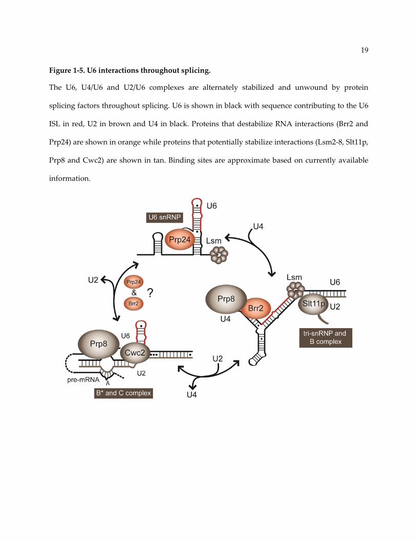
Figure 1‐5. U6 interactions throughout splicing.
The U6, U4/U6 and U2/U6 complexes are alternately stabilized and unwound by protein
splicing factors throughout splicing. U6 is shown in black with sequence contributing to the U6
ISL in red, U2 in brown and U4 in black. Proteins that destabilize RNA interactions (Brr2 and
Prp24) are shown in orange while proteins that potentially stabilize interactions (Lsm2‐8, Slt11p,
Prp8 and Cwc2) are shown in tan. Binding sites are approximate based on currently available
information.
20
1.3 Initial recognition of pre‐mRNA for splicing
As the pre‐mRNA transcript emerges from RNA polymerase II, it is recognized by the
U1 and U2 snRNPs, which commit the transcript to splicing. This so called A complex or pre‐
spliceosome forms prior to U6 association (Figure 1‐2). The 5’ splice site is the first portion of the
intron to emerge and is bound by U1 snRNP. U1 snRNA recognizes conserved sequences
adjacent to the 5’ splice site via base‐pairing [15]. While this binding event is reversible and
does not require ATP, stable U1 association is ATP dependent [18].
The branchpoint and 3’ splice site are recognized cooperatively by protein splicing
factors BBP/Mud2p [72, 73] and U2AF [74], respectively. However, S. cerevisiae has no U2AF
and does not require the 3’ splice site for the first step of splicing [75]. Interactions between
these complexes begin the process of positioning the substrate for splicing [15]. Replacement of
BBP/Mud2 by the U2 snRNP at the branchpoint is followed by ATP hydrolysis by the helicase
Sub2 (UAP56 in humans) [76] and facilitates formation of the pre‐spliceosome. U2 snRNA
initiates base‐pairing with the branchpoint sequence via a conserved stem‐loop, called the BSL
[77]. U2 snRNP proteins are required to stabilize the interaction between U2 snRNA and the
pre‐mRNA substrate [78] and remain with the spliceosome for most of the splicing cycle [3].
Finally, these snRNA‐mRNA interactions are proofread by the DExD/H box protein Prp5,
enabling spliceosome assembly to proceed to the next step [22].

21
1.4 Escort of U6 to the spliceosome
1.4.1 Properties of the U4/U6 complex
Following U6 snRNP formation, U6 and U4 snRNAs base‐pair within the U4/U6 di‐
snRNP independently of the pre‐mRNA (Figure 1‐2) [26, 27]. Evidence for this assembly
intermediate is provided by detection of U6 within free U6 snRNP, U4/U6 di‐snRNP and
U4/U6‐U5 tri‐snRNP in whole cell extract. (Note: “/” indicates the RNAs are base‐paired, while
“‐” indicates that the snRNPs associate without direct RNA interaction.) Additionally, in the
presence of ATP, tri‐snRNP breaks down into free U5 snRNP and U4/U6 di‐snRNP,
demonstrating that it is a stable intermediate in vitro [26, 27]. However, based on the
observation that U4/U6 di‐snRNP is rarely detectable in splicing extracts, it is unlikely that the
di‐snRNP is long‐lived before being incorporated into U4/U6‐U5 tri‐snRNP. U6 is expressed in
excess of U4, leading to accumulation of U6 snRNP and virtually undetectable levels of free U4
snRNP [26, 27].
The U6 snRNP protein Prp24 is thought to perform a “matchmaking” role by bringing
together the U4 and U6 snRNAs to form the stable core of the di‐snRNP (Figure 1‐6A) [79]. The
U4/U6 interaction is further stabilized by the Lsm ring [70], which is required for efficient di‐
snRNP formation (Figure 1‐5) [80]. Prp24 is not typically detected in the di‐snRNP and is thus
thought to disassociate just after U4/U6 formation (Figure 1‐2). Therefore, the di‐snRNP is
primarily composed of U4‐associated proteins [3] with the exception of the Lsm ring.
U6 and U4 RNAs form an extensive interaction composed of two intermolecular helices,
called U4/U6 Stem I and Stem II (Figure 1‐6) [26]. U4/U6 Stem II utilizes the U6 sequence
contained in the U6 ISL and is thought to act as a chaperone by inactivating U6 until
spliceosome assembly is complete [26]. Additionally, U4 forms a 5’ stem‐loop that includes a

22
UUCG tetraloop and a K‐turn motif (Figure 1‐6) [81]. The structure of the human 5’ stem‐loop
has been characterized in solution [82] and by X‐ray crystallography in complex with the Prp31
and 15.5K splicing factors [81] (Figure 1‐6B). This unique RNA fold induced by the 90° K‐turn
(Figure 1‐6B) may be required for recognition of the U4 snRNA in the spliceosome and escort of
U4/U6 to the next assembly step.
1.4.2 Tri‐snRNP assembly
The U4/U6 di‐snRNP stably associates with U5 and its associated proteins to form a
U4/U6‐U5 tri‐snRNP independently of the pre‐mRNA (Figure 1‐2). The U5 snRNP is thought to
perform a central role in regulating activation of the spliceosome [3]. U5 snRNA directly
contacts the 3’ splice site of the substrate and interacts with numerous proteins within the U5
snRNP that are essential to spliceosome assembly and catalysis. These factors include Prp8, the
largest protein in the spliceosome, which is thought to play a central regulatory role [83], and
Brr2, the helicase that may “switch on” the spliceosome by unwinding the U4/U6 complex
(Figure 1‐5) [84]. U4/U6 must remained paired until the tri‐snRNP has associated with the pre‐
spliceosome (Figure 1‐2). Therefore, the activity of Brr2 remains suppressed within the tri‐
snRNP, consistent with the observation that Prp8 can inhibit Brr2 [85]. Furthermore, association
of U5 snRNP with U4/U6 di‐snRNP does not appear to significantly alter the configuration of
interactions within the di‐snRNP [86].

23
Figure 1‐6. Structure of the U4/U6 complex.
A. Secondary structure of the U4/U6 snRNA complex (U6 is shown in red and orange based on
sequence conservation as in Figure 1‐4). The same U6 sequences involved in U6 ISL formation
form base‐pairs within U4/U6 Stem II. B. Crystal structure of the U4 5’ stem‐loop (dark gray)
bound by Prp31 (cyan) and 15.5K (lilac) splicing factors [81]. The U4 5’ stem‐loop contains a K‐
turn motif that induces a 90° bend in the RNA.

24
1.4.3 Alternative spliceosome assembly pathways
While independent formation of the pre‐spliceosome and the U4/U6‐U5 tri‐snRNP is the
most widely accepted model for spliceosome assembly, several studies have suggested that the
tri‐snRNP can pre‐assemble with U2 and U1. In the absence of pre‐mRNA, a portion of U2
snRNP associates with the U4/U6‐U5 tri‐snRNP [20], and this complex is stabilized in a strain
defective for U4/U6 unwinding [84]. Additionally, completely assembled spliceosome,
containing U1, U2, U4, U5 and U6 snRNPs (termed the penta‐snRNP) has been detected in the
absence of pre‐mRNA substrate [19]. A similar complex in which U2 and U6 are base‐paired has
also been detected in HeLa cell nuclear extract via psoralen crosslinking [87]. Therefore, the
spliceosomal snRNPs may be able to associate independently of pre‐mRNA. These alternative
assembly pathways further indicate the extent of heterogeneity of spliceosomal subcomplexes.
1.5 Activation and composition of the spliceosome
The U4/U6 complex persists through formation of the assembled spliceosome (B
complex, Figure 1‐2), at which point U6 can pair with U2. Detection of a U2/U4/U6 complex
(Figure 1‐7A) [68, 88] led to the hypothesis that the U2/U6 interaction is initiated in the B
complex by formation of U2/U6 Helix II (Figure 1‐5 and Figure 1‐7A). Helix II formation may be
initiated and/or stabilized by splicing factor Slt11p (Figure 1‐5), which has genetic interactions
with the U2 and U6 sequences in that region [89]. Slt11p also anneals and binds RNA duplexes
that contain two adjacent helical domains similar to U4/U6 Stem II and U2/U6 Helix II (Figure
1‐7A) [89].
The B complex is converted to the activated pre‐catalytic Bact complex through drastic
compositional changes (Figure 1‐2). While the B complex contains most proteins associated

25
with U1, U2 and the U4/U6‐U5 tri‐snRNP [90], more than half of these proteins are lost upon
activation through loss of the U1 and U4 snRNPs (Figure 1‐2) [90]. Release of the U4 snRNP
requires ATP‐dependent unwinding of the U4/U6 complex by Brr2 (Figure 1‐2) [84], which is a
Ski2‐like helicase with tandem helicase cassettes. The N‐terminus of Brr2 associates with the
Stem I region of U4/U6, implicating Stem I as the initial substrate [91]. Interestingly, Brr2
activity is modulated by the C‐terminus of Prp8 [92], which interacts with U4 RNA just
upstream of Stem I and U6 near the 5’ splice site recognition sequence [85]. This interaction
suggests that Prp8 may communicate appropriate recognition of the 5’ splice site by U6 snRNA
to Brr2, initiating spliceosome activation via U4/U6 unwinding.
The last remaining component of the U6 snRNP, the Lsm ring, is lost upon dissociation
of U4/U6 (Figure 1‐2 and Figure 1‐5). Unwinding of U4/U6 Stem II allows the U6 ISL to reform,
initiating formation of the RNA complex that comprises the core of the active spliceosome
(Figure 1‐7). Meanwhile, U1 snRNA is removed from the pre‐mRNA by the DExD/H box
protein Prp28 (Figure 1‐2) [22], enabling U6 to directly interact with the 5’ splice site. Because
U2 snRNA is already paired with the branchpoint, this transition brings together the two
components of the intron that participate in the first step of splicing.
Activation requires association of an additional protein complex called the Nineteen
Complex (NTC), although when the NTC joins the spliceosome is a matter of some dispute.
Immuno‐precipitation studies indicate that the NTC joins after U4 release [93]. However, more
recent proteomic studies suggest that the NTC is present prior to U4 release [90], if at sub‐
stoichiometric levels. Furthermore, several NTC‐related factors that are required for the second
step of catalysis are still missing in Bact complex, such as Prp22 and Prp16.

26
1.6 Interactions in the spliceosomal active site
1.6.1 U2/U6 is central to the active spliceosome
The U2/U6 snRNA complex resides at the core of the active spliceosome and is thought
to contribute to catalysis [28, 94]. The last snRNA complex to form during splicing, U2/U6, is
composed of a three‐helix junction in yeast, formed by two intermolecular helices, Helix I and
Helix II, and the U6 ISL (Figure 1‐7B) [23, 95]. Upstream of Helix I in U6 is the ACAGA box,
which base‐pairs to the 5’ splice site of the pre‐mRNA substrate (Figure 1‐7B). Across from the
ACAGA box in U6 is the branchpoint recognition sequence of U2. An additional intermolecular
helix, Helix III (Figure 1‐7B), has been detected genetically in the mammalian sequence [25].
Helices I and III bring the distal 5’ splice site and branchpoint of the pre‐mRNA into close
proximity in the active site of the spliceosome. Additionally, both the internal loop of the U6 ISL
(Figure 1‐7C) [62] and the invariant AGC triad (Figure 1‐7C) [24] in U6 are thought to
contribute directly to catalysis.
The exact secondary structure of the yeast U2/U6 complex has proven controversial due
to conflicting observations by structural [96] and genetic studies [23, 97, 98]. The human U2/U6
complex is thought to form a four‐helix junction (as depicted in the yeast sequence in Figure
1‐7D), that excludes a portion of Helix I, Helix Ib (Figure 1‐7A), in favor of a short stem‐loop in
U2 (U2 Stem I) [99] and an extended form of the U6 ISL [25]. The same structure has been
proposed for the yeast sequence (Figure 1‐7D) based on in silico energy minimization [100] and
NMR studies [96]. However, genetic experiments suggest that Helix Ib is essential for both steps
of splicing [97, 98] and that the four‐helix junction is either an intermediate structure between
the two steps of splicing or a fold induced by truncation of U2/U6 to make it amenable to NMR.

27
1.6.2 Metal ion coordination in U2/U6
The U6 ISL coordinates Mg2+ in a one by two internal loop (Figure 1‐7D). Mg2+
coordination has been attributed to the 5’‐pro‐S(P) oxygen of a conserved uracil residue in this
loop (U80) based on the observation that a phosphorothioate substitution at this position causes
the spliceosome to become dependent on thiophilic ions, such as Mn2+, for the first step of
splicing [62]. NMR analyses of the S(P)‐phosphorothioate U6 ISL reveal that the substitution
does not affect the overall structure of the RNA despite disrupting Mg2+ ion coordination [101].
Mutation of U80 to a guanosine is lethal in S. cerevisiae [24, 63], due to introduction of a G‐C pair
that causes a significant increase in the stability of the structure [102]. Interestingly, the metal
binding properties of U80 remain unperturbed in this mutant [102]. Taken together, these
results indicate that Mg2+ ion coordination in the ISL is achieved through highly localized
interactions.
The AGC triad of U6 has also been proposed to coordinate Mg2+ based on the analogous
metal binding site in the group II intron (Figure 1‐7D) [103]. RNAs derived from the human
U2/U6 sequence have limited catalytic activity in vitro and bind Mg2+ specifically at this site
[104, 105], suggesting that the spliceosome may also employ a two Mg2+ ion mechanism during
catalysis. However, the functionality of this metal binding site has yet to be characterized in
vivo. Therefore, the possibility remains that other factors, such as proteins, may either support
metal ion coordination or provide functional groups that contribute to catalysis.
28
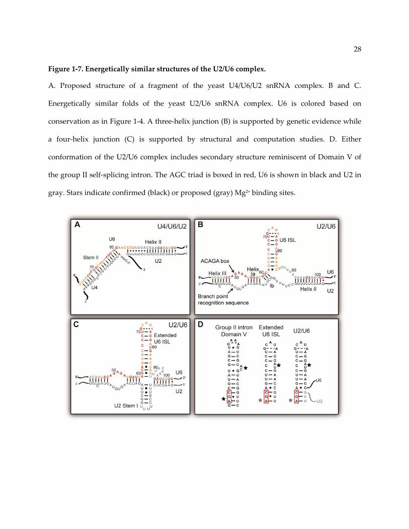
Figure 1‐7. Energetically similar structures of the U2/U6 complex.
A. Proposed structure of a fragment of the yeast U4/U6/U2 snRNA complex. B and C.
Energetically similar folds of the yeast U2/U6 snRNA complex. U6 is colored based on
conservation as in Figure 1‐4. A three‐helix junction (B) is supported by genetic evidence while
a four‐helix junction (C) is supported by structural and computation studies. D. Either
conformation of the U2/U6 complex includes secondary structure reminiscent of Domain V of
the group II self‐splicing intron. The AGC triad is boxed in red, U6 is shown in black and U2 in
gray. Stars indicate confirmed (black) or proposed (gray) Mg2+ binding sites.

29
1.6.3 Protein active site partners.
In the spliceosome, protein partners are likely to directly participate in catalysis or at least
position the snRNA and pre‐mRNA. While the similarities between the spliceosome and self‐
splicing introns has led to the hypothesis that the spliceosome is a ribozyme, self‐splicing
introns require a helper protein to undergo the branching reaction [106]. This protein‐assisted
reaction may represent an evolutionary step toward the spliceosome and suggests a more
central role for proteins in the spliceosomal active site. However, by the time the spliceosome is
catalytically active, U2 and U6 have lost the majority of their associated proteins. Therefore,
protein partners must come from other spliceosomal subcomplexes [3].
One key player in spliceosome catalysis is Prp8. This U5 snRNP protein is the largest
protein in the spliceosome at ~230‐280 KDa and is remarkably well‐conserved, considering its
size [83]. While all of the functions of Prp8 are not known, it is thought to be a hub for
regulatory interactions within the spliceosome. Prp8 directly contacts both the pre‐mRNA and
U6 at the 5’ splice site (Figure 1‐5) [107]. Much of the structure of Prp8 remains
uncharacterized, but crystal structures exist for two domains at the C‐terminus. The first is a
JAB/MPN domain that contains many of the mutations implicated in retinitis pigmentosa [30,
108]. The second, Domain IV, is an RNase‐H‐like (or β‐finger) domain [109‐111], named for an
RNase‐H fold that lacks the active site residues responsible for hydrolysis. Domain IV has an
internal β‐finger extension [109] that contains residues implicated in the first or second steps of
splicing [109]. This type of protrusion is common among ribosomal proteins and frequently
contacts the ribosomal RNA [109]. Additionally, Domain IV has recently been demonstrated to
specifically interact with the region around the ACAGA box of U6 [85], suggesting a direct role
in the spliceosomal active site.

30
Another potential active site component is Cwc2, an NTC component. Cwc2 interacts
directly with U6 snRNA [112] and pulls down both U6 and U2 RNAs from spliceosomes stalled
before the first or second step of splicing [112]. Additionally, two of the domains of Cwc2 are
canonical RNA binding domains: a zinc finger and an RRM. Together they form a compact
cooperative unit that displays a continuous electropositive surface [113] that encompasses
residues required for RNA binding. Additionally, both RNA‐binding domains are required for
full affinity, suggesting that Cwc2 recognizes multiple sites in U6 [113].
The DExD/H box ATPase Prp16 has been implicated in rearrangement of the substrate and
snRNAs between the two steps of splicing [22]. Prp16 has strong genetic interactions with
U2/U6 Helix I [114], near the helical junction and substrate binding sites. Transition from the
first to second step of splicing requires repositioning of the pre‐mRNA substrate and potentially
also U2/U6. Prp16 is additionally responsible for proofreading 5’ splice site choice during the
first step of splicing [22]. Like some of the other ATPases that act during splicing, Prp16 has the
power to discard non‐ideal substrates, in this case those that lack a proper 5’ splice site [115].
Another DEAH box ATPase, Prp2, is also implicated in this rearrangement [22], targeting a
region of the intron just downstream of the branchpoint [116]. Brr2 has also recently been
implicated in this transition, due to genetic interactions with second‐step factors and newly
discovered interactions with the splice sites and branchpoint of the pre‐mRNA [91] as well as
Prp2 [116].

31
1.7 Spliceosome disassembly and snRNA recycling
After the two steps of splicing proceed, the spliceosome is broken down into its
individual components. The ligated exons and lariat intron are extracted and the snRNPs are
returned to their individual forms for further rounds of splicing. Interestingly, premature
substrate rejection from the C complex is reversible when a disassembly factor, Prp43, is not
present [115]. The requirement for Prp43 implies that the spliceosome does not spontaneously
decompose upon substrate loss, but undergoes an active disassembly process.
Spliceosome disassembly requires ATP hydrolysis by two DExD/H box helicase‐type
proteins, Prp22 and Prp43. After the two steps of splicing, the resulting ligated exons are
proofread by Prp22 (Figure 1‐8) [117]. ATP hydrolysis by Prp22 releases the ligated exons
which are further modified to become mature mRNA. After this release step, the lariat intron
presumably forms a stable complex with NTC proteins and the U2/U6‐U5 snRNP. This model is
supported by the existence of a highly stable U2/U6‐U5 complex in S. pombe that contains both
NTC proteins and the lariat intron [118], although this complex is more transient in other
organisms.
The next step in disassembly is release of the lariat intron by the Prp43/Ntr1/Ntr2
complex. In extracts depleted for Ntr1 and Ntr2, the spliceosome can still assemble but cannot
be recycled (Figure 1‐8) [119]. The U5 snRNP is also thought to disassociate at this step through
interaction with Ntr2 [119]. After removal of the lariat intron from the C‐complex, the 2’‐5’
linkage must be resolved through a de‐branching reaction performed by Dbr1 (Figure 1‐8) [120].
Interestingly, the DBR1 gene is not essential in S. cerevisiae [16] or S. pombe [121]. Nonetheless,
deletion of this gene results in accumulation of lariat intron [16], indicating that linearization of

32
lariat introns is required for degradation to proceed efficiently. Interestingly, Prp43 and Prp22
share a homologous C‐terminal domain with Prp16 and Prp2 [122]. Crystal structures of this
domain in Prp43 [123, 124] and Prp22 [122] reveal a Sec63‐like domain, similar to Brr2 [29],
further implicating both of these essential factors in RNA‐recognition and unwinding.
While the lariat and U5 snRNPs dissociate upon ATP hydrolysis by Prp43, the U2/U6
snRNA complex may still remain intact (Figure 1‐2). Brr2, the same helicase that unwinds the
U4/U6 complex (Figure 1‐8) [84], has been implicated in disassembly, potentially by unwinding
U2/U6. To prevent premature abortion of splicing, Brr2 must remain silenced after unwinding
the U4/U6 complex until the second step of splicing is completed. The activity of Brr2 is
controlled by interaction with Snu114, a GTPase involved in spliceosomal remodeling [125], and
Prp8 [85]. Because Prp8 is intricately involved in the active site, it could provide the signal for
spliceosome disassembly.
Prp24 has also been implicated in U2/U6 destabilization based on genetic interactions
with Brr2 [126] and Prp21 [127]. However, Prp24 leaves the U6 snRNP very early in
spliceosome assembly upon formation of the U4/U6 di‐snRNP. Therefore, the observation that
Prp24 interacts with a U5 snRNP protein (Brr2) and a component of the SF3a subunit of the U2
snRNP (Prp21) suggests that Prp24 must rejoin the spliceosome before disassembly. This is
further supported by evidence for an interaction between Prp24 and Prp17 [128], a component
of the NTC that does not join the spliceosome until activation. While the exact role of Prp24 in
disassembly remains unclear, it certainly plays an important role in recruiting U6 snRNA from
post‐catalytic spliceosomes for further rounds of assembly [79].

33
Figure 1‐8. Current model of spliceosome disassembly.
As with spliceosome assembly, disassembly occurs through an ordered series of steps that
require ATP hydrolysis by splicing factors. The pre‐mRNA components are released first for
either further processing and nuclear export or degradation. Individual snRNPs (or the
Nineteen Complex – NTC) are depicted as circles. snRNPs that interact through snRNA pairing
are shown squished together (U2/U6). Exons are shown as black lines and the intron/lariat in
gray. The 5’‐7‐methylguanylate mRNA cap is depicted as a pink circle. Splicing factors
implicated at each step are indicated adjacent to the corresponding arrow.

34
1.8 Structural studies of U6 complexes
The currently available structures of U6‐containing complexes exist at two extremes of
structural characterization. On one end are small but highly detailed NMR structures of the U6
ISL that provide insight into the exact mechanism of Mg2+ coordination [59, 96]. NMR studies
have also provided valuable information about the secondary structure of the U2/U6 complex
[99], but only minimal insight into the tertiary fold. On the other end of the spectrum are cryo‐
EM studies that reveal the global characteristics of U6‐containing particles, such as the U6
snRNP [57], the U4/U6‐U5 tri‐snRNP [86] and the C complex, [129] but provide little detail. Due
to the large discrepancy in scale and resolution of these methods, synthesis of the resulting
information has thus far proved difficult.
Significant effort is underway to bridge this gap through a variety of approaches. Recent
structural studies have begun to characterize larger U6 complexes, including the structure of a
domain of Prp24 bound to fragments of U6 [67] and modeling based on functional and
structural data of the Prp24‐U6 complex [69]. Additionally, presented herein is a structural
study of the entire base‐paired region of the yeast U2/U6 complex [95]. This structure represents
a first step in piecing together a structural model of the spliceosomal active site. Continued
expansion of the size limits of NMR through coupling with other methods, such as small angle
X‐ray scattering (SAXS) and cryo‐EM, will improve our ability to analyze the structures of U6
containing complexes.
Other methods, such as X‐ray crystallography, have proved challenging due to the
heterogeneity of spliceosome preparations. However, other complementary approaches may
aid this endeavor, such as discovery of small molecule inhibitors that stall spliceosomal

35
complexes [130, 131], potentially enabling production of homogenous subcomplexes.
Additionally, cryo‐EM studies continue to improve through the use of techniques such as
labeling pre‐mRNA and spliceosomal components to identify the locations of important
elements [132].
1.9 Dissertation overview
The work described here aims to generate an improved understanding of the structure
and function of the U2/U6 snRNA complex and its relationship with other U6‐containing
complexes. The base‐paired region of U2/U6 is a minimum of 107 nucleotides. Analysis of a
structure of this size in solution necessitated improved methodology and integration of SAXS
with traditional NMR techniques. Chapter 2 focuses on the use of SAXS with nucleic acids, a
methodology that is still under development. This protocol was used in conjunction with
traditional NMR techniques to develop a new approach for analyzing large RNAs in solution,
outlined in Chapter 3. I used this approach to solve the structure of the yeast U2/U6 complex,
which is the largest joint NMR/SAXS study of a nucleic acid to date. The NMR structure of a
smaller component of this complex, the essential U2/U6 Helix I interaction, is discussed in
greater detail in Chapter 4.
Chapters 5 and 6 explore the unusual properties of a U4/U6 triple mutant strain that
contains almost no detectable U4/U6 complex. Chapter 5 discusses a multifaceted analysis of the
effects of stability changes in the U2/U6 and U4/U6 complexes using biophysical, biochemical
and genetic methods. This study resulted in discovery of a transient and therefore previously
undetected spliceosome disassembly intermediate, the U2/U6 snRNP, which represents a
paradigm shift in spliceosome disassembly and U6 snRNA recycling. Chapter 6 describes U4

36
and Prp24 bypass and truncation experiments as well as construction of an S. cerevisiae strain
that can be used for genetic analyses of U4, U6 and PRP24 alleles simultaneously. Chapter 7
summarizes my thesis work and examines potential future directions based on the newly
developed tools and results presented herein.
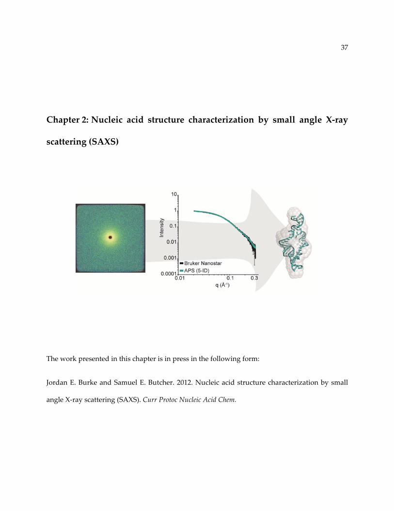
37
Chapter 2: Nucleic acid structure characterization by small angle X‐ray
scattering (SAXS)
The work presented in this chapter is in press in the following form:
Jordan E. Burke and Samuel E. Butcher. 2012. Nucleic acid structure characterization by small
angle X‐ray scattering (SAXS). Curr Protoc Nucleic Acid Chem.
38
2.1 Abstract
Small angle X‐ray scattering (SAXS) is a powerful method for investigating
macromolecular structure in solution. SAXS data provide information about the size and shape
of a molecule with a resolution of approximately 2‐3 nm. SAXS is particularly useful for the
investigation of nucleic acids, which scatter X‐rays strongly due to the electron‐rich phosphate
backbone. Therefore, SAXS has become an increasingly popular method for modeling nucleic
acid structures, an endeavor made tractable by the highly regular helical nature of nucleic acid
secondary structures. Recently, we used SAXS in combination with NMR to filter and refine all‐
atom models of a U2/U6 small nuclear RNA complex. In this unit we present general protocols
for sample preparation, data acquisition, and data analysis and processing. Additionally,
examples of correctly and incorrectly processed SAXS data and expected results are provided.

39
2.2 Introduction
2.2.1 Overview
This unit contains a general procedure for characterizing nucleic acid structure using small
angle X‐ray scattering (SAXS). SAXS is a powerful method for analyzing the global shape of
macromolecules in solution. Because SAXS measures the contrast in scattering between the
macromolecule and buffer, it is particularly well‐suited for nucleic acids which have high
contrast due to the electron‐rich phosphate backbone. SAXS provides essential information
about the size and shape of the molecule and can be used to generate low resolution models for
comparison with homologous crystal or NMR structures. All‐atom models can also be filtered
and refined against SAXS data.
Determination of novel nucleic acid structures is of great importance for understanding
their biological roles; however, it poses a considerable challenge for traditional structural
methods. Nucleic acids can be difficult to crystallize and NMR structure determination is
challenging due to low proton density, resulting in fewer observable signals, and spectral
overlap due to limited chemical shift dispersion. Because of these challenges, characterization
of nucleic acids by low resolution methods is becoming increasingly popular. Examples of
nucleic acid studies using SAXS include the investigation of conformational changes in a DNA
Holliday junction [133]; measurement of single stranded DNA and RNA persistence lengths
[134], time‐resolved studies of RNA folding pathways [135‐137] and structural studies of
ribozymes [138, 139], tRNA and tRNA‐like structures [140‐142], riboswitches [143‐147] and
spliceosomal RNAs [95].

40
SAXS is highly complementary to both X‐ray crystallography and NMR. Few nucleic acid
molecules exceeding 75 nucleotides (nt) have been solved by NMR due to the challenges of
spectral overlap and fast relaxation. In contrast, SAXS is appropriate for nucleic acids from 25
to hundreds of nucleotides in size. Very small nucleic acids (< 25 nt) may not be amenable to
SAXS as their size is at or below the resolution limit (~20‐30 Å). SAXS requires significantly less
sample than NMR and data collection can take as little as a second or less at synchrotron
radiation sources. Using synchrotron radiation, nucleic acid dynamics can be measured with
SAXS in real time [148]. SAXS also allows for selection of ensembles of models that predict the
range of motions sampled in solution [149, 150].
The workflow for this method is outlined in Figure 2‐1. The end goal of SAXS
characterization is often a low resolution envelope (referred to as an ab initio model).
Additional information about the secondary structure and long range contacts from other
methods such as chemical probing, NMR or bioinformatics is indispensable to obtaining a high
quality ensemble of structural models. For a recent review on combining NMR and SAXS data
to investigate RNA structures, see [151].

41
Figure 2‐1. General scheme for characterization of RNA using small angle X‐ray scattering.
Ovals indicate procedures discussed in other publications (see Discussion).
42
2.2.2 Sample Preparation
It is crucial to obtain a pure, monodisperse sample before data collection to ensure that all
subsequent data processing and modeling steps are valid. Formation of unwanted higher order
complexes or sample degradation can distort X‐ray scattering and result in low quality
structural models [152]. Unfortunately, poor sample quality is not always apparent until after
extensive data analysis. Initial analysis will provide some information about sample quality,
but it is essential to assess the sample using other methods as well (outlined in Section 2.3.1).
Dynamic light scattering (DLS) is a powerful method for assessing the size and homogeneity of
macromolecules [153, 154], and can be used to ascertain sample quality prior to SAXS data
collection. DLS determines the diffusion coefficient of a molecule by measuring time‐
dependent fluctuations in the intensity of light scattering. The diffusion coefficient is used to
calculate the hydrodynamic radius and size distribution of particles in the sample [153].
The initial steps in sample preparation, construct design, DNA transcription and
purification have been described in detail elsewhere [155‐157]. The steps following purification
employ the same buffer that will be used for SAXS data collection, so it is useful to decide on
the buffer composition early. SAXS samples often contain Tris as the buffering agent due to its
ability to scavenge hydroxyl radicals generated by exposure of the solvent to X‐rays. Phosphate
buffer is generally not recommended because it reduces the contrast between the sample and
buffer scattering. In order to minimize the effects of interparticle repulsion, nucleic acid
samples require at least 100 mM monovalent ionic strength (sodium chloride or potassium
chloride) and 1‐40 mM magnesium chloride (optional), which is often important for folding.
Other small molecules, such as ligands, may also be added.

43
One robust method for obtaining a homogeneous, monodisperse sample is to use high
resolution size exclusion chromatography [152]. RNA molecules can form higher order
complexes after in vitro transcription, and these complexes (which are often bi‐ or tri‐molecular)
must be separated from the desired RNA species. It is important to choose a size exclusion
column based on the size and properties of the molecule. This technique is also useful for
isolating homogeneous nucleic acid complexes or nucleic acid‐protein complexes.
Buffer matching and accurate concentration determination are also crucial to SAXS
characterization. Effective buffer matching is achieved through extensive dialysis. An accurate
concentration is required for data processing and can be determined by hydrolyzing a small
amount of the sample in KOH and measuring the absorbance at 260 nm (A260) [158].
2.2.3 Data acquisition
SAXS data acquisition can be performed using either a synchrotron or bench top X‐ray
source. Synchrotron sources have much greater X‐ray flux and therefore allow for much faster
data collection with higher signal to noise (Figure 2‐2A). This kind of source is ideal for kinetic
experiments or for samples that are unavoidably dilute or degrade very quickly. Additionally,
high flux synchrotron radiation allows for collection of wide angle X‐ray scattering (WAXS)
which can be used to evaluate buffer matching. Typically, experimental arrangements at
synchrotron sources include a flow cell apparatus to move the sample across the X‐ray beam,
which minimizes radiation damage during data collection. However, due to this arrangement,
larger sample volumes (~250 μl) may be required. Alternatively, bench top SAXS instruments
are also appropriate for use with nucleic acids, despite having lower flux than synchrotron
sources (Figure 2‐2A). Bench top X‐ray sources may be point or line collimated. Line collimated
sources can generate high flux across a larger volume of sample due to a slit‐shaped beam
44
geometry; however, data processing requires a deconvolution step, called “desmearing” [159].
Point collimated sources focus a narrow X‐ray beam on only a small area of the sample, and do
not require desmearing. In some cases, data acquisition for the sample may be very long (e.g.
up to 12 hours for a dilute sample using a bench top X‐ray source). In this case, data collection
time for the buffer can be reduced but must be scaled based on X‐ray intensity at the time of the
experiment and can introduce additional noise. The requisite sample volume for a capillary
used in bench top SAXS instruments can be as low as 20‐30 μl.
Biological SAXS typically requires data in the range of 0.1° < 2θ < 5° or 0.01 < q < 0.35 Å‐1 for
structure characterization (Figure 2‐2A), where q is a transform of the scattering angle:
Equation 2‐1
and λ is the X‐ray wavelength (usually 1.54 Å). This data range can be obtained with a sample
to detector distance of 67‐100 cm. Collection of WAXS data (0.3 < q < 2 Å‐1) will reveal a
scattering peak resulting from the buffer. This peak is useful for adjusting buffer matching, but
is not absolutely necessary if concentration determination and buffer matching are performed
properly. WAXS is typically detected at a sample to detector distance of 30 cm. If both SAXS
and WAXS are being collected, a longer SAXS sample to detector distance of 200‐400 cm can be
used to obtain scattering at smaller angles (q < 0.01 Å‐1) as scattering at wider angles is
redundant with WAXS. Simultaneous SAXS and WAXS data collection will ensure consistency
in the overlapped scattering region used to merge the two data sets. Often, an arrangement
with two detectors is available for this purpose at synchrotron facilities.
45
2.2.4 Data analysis
Initial analysis of SAXS data should be performed directly after data acquisition to rapidly
assess sample quality and experimental setup. This includes buffer subtraction, Guinier
analysis and Kratky analysis. Buffer subtraction may need to be fine‐tuned at a later time,
especially if WAXS data are available. Guinier analysis will provide an approximate radius of
gyration and is a good method for sample quality assessment (see Section 2.3.3). Kratky
analysis provides information about the general conformation of the molecule, such as the
extent of folding and whether the molecule is globular, extended or unfolded.
After data acquisition, more complex data analysis such as determination of the pair‐
distance distribution function (PDDF) and ab initio modeling can be performed. The PDDF is
the sum of all inter‐atomic pair‐distances in the molecule and is determined by an indirect
Fourier transform of the scattering data using the program Gnom [160]. Determination of the
PDDF provides the maximum dimension of the molecule (Dmax – note: also sometimes called
Rmax) as well as an idealized scattering curve that is extrapolated to q = 0 Å‐1. This scattering
curve can be used to calculate a low resolution ab initio envelope of the nucleic acid composed
of dummy atoms or beads. The ab initio model provides the global fold of the molecule and can
be fitted to existing structures or models. Additionally, ≥ 11‐12 base‐pair extensions can be
added to different helices in the nucleic acid to identify structural features [95, 141, 145],
provided such extensions do not disrupt the overall fold. These extensions will manifest as ≥ 30
Å elongations in the envelope.

46
2.2.5 All‐atom modeling
In parallel with data collection and analysis, secondary structure, if not known a priori, must
be determined. This can be achieved with computational tools such as MFOLD [161], MC‐
FOLD [162], or RNAstructure [163]. However, nucleic acids frequently form alternative
conformations that are similar in free energy. Therefore, the predicted secondary structure
must often be determined experimentally using biochemical methods [164, 165], phylogenetic
covariation analysis [166], or NMR for nucleic acids that are on the order of 100 nt or less [155].
The secondary structure informs the overall conformation of the RNA [167] and can be used to
build a library of models to filter against SAXS data (see Discussion). While obtaining a low
resolution envelope for a highly flexible or heterogeneous molecule is very challenging,
flexibility can be modeled by a combination of molecular modeling, molecular dynamics
simulations and SAXS prediction tools that have ensemble modeling capabilities, such as
ensemble optimization method or EOM [149, 150, 168].

47
2.3 Materials and Methods
2.3.1 Sample preparation
Large quantities of RNA can be prepared by either in vitro transcription [155, 156, 169] or
in E. coli using recombinant technology [157]. Typically, RNAs > 80 nt are transcribed in vitro
from a linearized plasmid containing the template for the RNA sequence, created using
standard cloning techniques [170]. The level of purification achieved using these methods may
be adequate for some RNAs; however, further steps are required for most RNAs to obtain the
quality of sample necessary for SAXS characterization. Depending on the number of
experiments, X‐ray source and sample handling arrangement, 0.5‐3 mg of nucleic acid should
be sufficient. If purified using denaturing methods, we recommend re‐folding RNAs after
purification to eliminate formation of higher order multimeric species. Alternatively, RNAs
may be purified using non‐denaturing methods, circumventing the need for a refolding step
[171].
Materials
Tris base, 99% pure
Ethylenediamine tetraacetic acid, disodium salt dihydrate (EDTA), > 99% pure
Sodium chloride (NaCl) or potassium chloride (KCl), >99% pure
Magnesium chloride (MgCl2), >99% pure (optional)
Potassium hydroxide (KOH), 89% pure
Sodium acetate, anhydrous, >99% pure
Ethanol, 95%
0.22 μm filter flask, 1 L, Millipore or GE Healthcare
48
0.20 μm syringe filters, Sartorius Stedim
0.22 μm SpinX cellulose acetate filters, CoStar
Centrifugal filters, regenerated cellulose, 15 ml and 0.5 ml, Amicon® Ultra
Dialysis cassettes, Slide‐A‐Lyzer® Thermo Scientific, 0.5‐3 ml capacity
100 μl syringe with 23 mm, 22 gauge, blunt end needle, Hamilton (to minimize sample
retention)
GE Healthcare HiLoadTM 16/60 Superdex 75 or 200 prep grade column
FPLC system (such as ÄKTAFPLCTM) equipped with on‐line UV monitor at 254 nm, 100
μl loading loop and fraction collector
Centrifuge capable of holding 50 ml conical tubes
Microcentrifuge
Nanodrop ND‐1000 spectrophotometer or other UV spectrophotometer
Analyze sample homogeneity and re‐fold (optional)
1. Resuspend nucleic acid sample in the appropriate volume of SAXS buffer.
Add enough buffer to obtain a concentration of 5‐10 mg/ml.
2. Assay a small aliquot (0.1‐0.50 nmol or 10‐15 μg) for folding homogeneity by non‐
denaturing polyacrylamide gel electrophoresis (29:1 acrylamide: bisacrylamide, 88 mM Tris
borate).
A 6% (w/v) polyacrylamide solution works well for most RNAs 50‐200 nt. Toluidine blue (tolonium
chloride) staining is usually adequate for detection of most species.
3. Examine the gel. If only one band is visible, proceed to step 8.
49
The presence of additional, slowly migrating species is likely indicative of bi‐ or tri‐molecular complex
formation. If these bands are minor (~ <10%), size exclusion chromatography (step 8) may be
adequate to remove these species. The following refolding steps will be necessary for those samples
with significant folding heterogeneity.
4. Precipitate the RNA in 0.3 M sodium acetate, pH 5.2 and 3 volumes of ethanol, and
resuspend the sample in a large volume of buffer such that the RNA concentration is < 10
μM.
Concentration and ionic strength may need to be adjusted depending on the properties of the nucleic
acid. In our experience, refolding in low ionic strength buffers (e.g. 10 mM Tris pH 7.0, 50 μM
EDTA) can successfully reduce the formation of multimeric species. Use an elongated tube, such as a
15 ml Falcon tube, to maximize surface area for efficient heating and cooling of samples.
5. Heat the sample to 90°C for 2 minutes.
6. Immediately place the sample on ice and allow to cool completely.
7. Repeat steps 2‐3 to assay the folding homogeneity of the sample.
Repeat this procedure as necessary, varying buffer composition or sample concentration to achieve
homogeneous folding.
Purify the sample by size exclusion chromatography
8. Prepare 4 L of the buffer that will be used for SAXS data collection (see Section 2.2.2) and
filter using a 0.22 μm filter flask.
2 L will be used for size exclusion chromatography and 2 L will be used later for dialysis. Store at
4°C for up to one month.
9. Concentrate the folded RNA using a centrifugal filtration device to a volume of 110‐120 μl
according to the manufacturer’s instructions.

50
10. At the same time, equilibrate the size exclusion column with at least 3 column volumes of
SAXS buffer.
11. Inject the sample using a 100 μl loop with the recommended low retention syringe and
needle.
10‐20 μl of sample will be retained in the needle and can be flushed out with buffer and either loaded
onto the column or saved.
12. Elute the sample using the same buffer and collect 1 ml fractions.
Calibration with protein standards can be very misleading for prediction of elution volume. Nucleic
acid molecules of the same molecular weight as proteins standards often elute at a significantly
different volume than expected.
13. Remove 10‐15 μl of each fraction with absorbance at 254 nm and analyze by non‐denaturing
PAGE as in step 2.
14. Pool the fractions that contain only the desired species.
15. Concentrate the pooled fractions using a centrifugal filter until the concentration of the
nucleic acid is ~ 3 mg/ml as determined by UV absorbance at 260 nm (A260).
A260 extinction coefficients are: A: 15.02 mM‐1cm‐1; C: 7.07 mM‐1cm‐1; G: 12.08 mM‐1cm‐1 and U:
9.66 mM‐1cm‐1 [158]. The molar masses of nucleotide monophosphates are AMP: 347.22 g/mol; CMP:
323.20 g/mol; GMP: 363.22 g/mol; GTP: 523.18 g/mol and UMP: 324.18 g/mol. Total volume
should be 0.5‐1 ml. Proceed immediately to step 16.
Dialyze the sample to achieve buffer matching
16. Prepare a dialysis cassette in 1 L of SAXS buffer according to the manufacturer’s
instructions.

51
17. Using a 1 ml syringe, load 0.5‐1 ml of RNA sample into the dialysis cassette according to the
manufacturer’s instructions.
18. Dialyze for 8‐12 hours with stirring at 4°C.
19. Exchange the buffer for 1 L of fresh SAXS buffer and continue dialysis for another 8‐12
hours at 4°C.
20. Remove the sample from the dialysis cassette.
Ideally, the RNA should be used as soon as possible after purification [152]; however, this is not
always practical. RNA can be stored at this point 4°C for a few hours, but should be flash frozen (see
step 25) as soon as possible.
21. Filter 50 ml of the dialysate from step 19 through a 0.2 μm syringe filter.
Store up to 1 week at 4°C or for longer periods at ‐20°C.
Prepare a dilution series and determine sample concentration
22. Remove 1 μl of the RNA sample and dilute accordingly to obtain an approximate
concentration based on the A260.
23. Using the filtered dialysate from step 21, dilute the RNA sample serially such that the
lowest concentration is near 0.5 mg/ml.
The sample volume will depend on the sample handling arrangement for the instrument. Contact the
facility before sample preparation to obtain this information. Serial dilutions may also be prepared at
the facility and concentrations determined after data collection given that the sample can be
recovered.
24. Remove 1 μl from each sample in the dilution series and add to an Eppendorf tube
containing 1 μl of 1 N KOH with 8 μl of ddH2O. Incubate the reserved KOH solutions at
room temperature overnight to hydrolyze.

52
25. At this point, flash freeze the samples from step 23 by dropping into liquid nitrogen. Store
at < ‐80°C until data collection.
26. Obtain an exact concentration of the hydrolyzed samples by measuring the A260 and using
the extinction coefficients listed above.
27. Immediately before data collection, thaw samples and load into 0.2 μm spin filters.
28. Centrifuge at >15,000 x g for 1 minute. The final sample will be the flow through.
2.3.2 SAXS data acquisition
Data acquisition procedures vary widely depending on the X‐ray source (synchrotron or
bench top) and the exact instrumental setup. It is best to consult with the facility you will be
using ahead of time to obtain information about experimental setup, sample volume and other
important parameters. The protocol outlined below is the general workflow during data
acquisition; however, this procedure may change depending on the instrument and facility.
Materials
Silver(I) behenate (AgBe)
Distilled deionized water
1‐1.5 mm quartz capillary (supplied with instrument)
Glassy carbon (optional, supplied with instrument)
Purified nucleic acid from Section 2.3.1
Reserved filtered dialysate from Section 2.3.1
SAXS instrument – approximately 67‐100 cm sample to detector distance
Additional detector for WAXS (optional) – 30 cm sample to detector distance

53
Standard sample: lysozyme (Fluka), glucose isomerase (Hampton research) or standard
RNA sample (Table 2‐1)
Steps
1. Before data collection, obtain scattering from a calibration standard such as AgBe
AgBe has a well characterized D‐spacing of 58.38 Å that results in a scattering pattern composed
of distinct rings [172]. This is used as a standard to precisely measure the sample to detector
distance.
2. If using a bench top instrument, measure the scattering intensity of the X‐ray source
through glassy carbon.
The incident X‐ray beam cannot be detected due to the beam stop and potential damage to the
detector. Glassy carbon is a strongly scattering material that allows for quantitation of beam
intensity [173]. This value is important for standardization of the intensity of the X‐ray source
from one data set to the next.
3. Before starting data collection, ensure that the capillary is properly aligned in the beam. Test
the capillary position by exposing the empty capillary to X‐rays for a short interval.
Improper alignment will result in asymmetric parasitic scattering around the beam stop. Ideally,
the same capillary should be used for buffer and sample. Alternatively, an “empty” exposure of
the capillary can be subtracted from the data to adjust for different capillaries.
4. Fill the capillary with ddH2O and perform a short scan to determine the water scattering
(optional).

54
This scan be anywhere from 0.1‐20 seconds for synchrotron radiation and up to 5 minutes for a
bench top source. H2O scattering is often subtracted from all subsequent scans (including buffer
and sample scans) to improve background subtraction.
5. Load the appropriate amount of buffer into the capillary.
Because the sample chamber is under vacuum in bench top instruments, the sample can sometimes be
evacuated from the capillary if it is not properly sealed. Take a 10 second scan with glassy carbon
between the sample and the detector to determine the absorbance of the buffer – typically a 10 fold
decrease in transmission is observed if the sample is still in the capillary.
6. Acquire buffer scattering data.
This buffer should be the dialysate from step 21 of Section 2.3.1. Data acquisition time should be the
same for buffer and sample and is typically 1‐20 seconds at a synchrotron source or 1‐6 hours on a
bench top source.
7. Acquire scattering for the most dilute sample (see step 6 above for acquisition time
suggestions).
8. Repeat steps 6‐7 for standard samples and all experimental samples.
9. Reduce the two‐dimensional data from the detector to a one‐dimensional scattering curve
(Figure 2‐2A) based on the calibration performed at the beginning of data acquisition (step
1).
This will also convert the angle (θ) to a q value. Desmearing may be necessary at this step if
using a line collimated X‐ray source. This step can be performed using a number of different
software tools, which are usually provided by the facility. Otherwise, Data Squeeze
(www.datasqueezesoftware.com) is available for free and has the same capabilities. The

55
Advanced Photon Source also provides a SAXS processing package with these capabilities for use
in Igor Pro (http://usaxs.xor.aps.anl.gov/staff/ilavsky/ExtendingTheCode.html).

56
Figure 2‐2. Data reduction and buffer subtraction.
A. Sample X‐ray scattering of a 28.2 KDa RNA at 1 mg/ml concentration from either a
synchrotron (Advanced Photon Source) for 3 minutes or bench‐top instrument (Bruker
Nanostar) for 4 hours (see Section 2.3.2). B. SAXS and WAXS data from a 28.2 KDa RNA
demonstrating accurate and inaccurate buffer subtraction (see Section 2.3.3).

57
Table 2‐1. SAXS standard samples.
Molecule, Conditions MW (KDa) Rg (Å) (± 1)
Lysozyme1
8 mg/ml, 40 mM acetic acid, pH 4.0, 50 mM NaCl 14.7 13
Glucose isomerase2
5 mg/ml, 100 mM Tris, pH 8.0, 1 mM MgCl2 173 33
Tetraloop‐receptor RNA3
1‐2 mg/ml, 50 mM Tris, pH 7.0, 150 mM NaCl, 2 mM MgCl228.2 25
1[174],2[175],3[176]

58
2.3.3 SAXS data processing and analysis
Introduction
SAXS data processing is an iterative process in which the quality of the data and the
characteristics of the sample are assessed at every step. It is advantageous to perform all data
processing steps on a well characterized, standard molecule as a positive control to ascertain
that calibration has been performed properly. Most data processing steps will use Primus [177],
a program in the ATSAS suite of software; however, programs like Igor Pro or Gnuplot may
also be used for early steps in processing, such as buffer subtraction and Guinier analysis.
DAMMIN [178] and DAMMIF [179] are currently the best programs for calculating low
resolution ab initio structures (or “envelopes”) of nucleic acids. Despite its prevalent use,
DAMMIF is limited in use with nucleic acids because it is optimized for use with proteins.
Specifically, DAMMIF is dependent on prediction of the scattering curve of the low resolution
envelope using form factors derived from protein composition. When used with nucleic acids,
the result is inflation of the low resolution envelope. Despite this issue, DAMMIF can be used
to approximate nucleic acid envelopes; however, each molecule will require different
parameters. Therefore, it is important to become familiar with the documentation
(http://www.embl‐hamburg.de/biosaxs/manual_dammif.html). To obtain a final, averaged
envelope, the DAMMIF models are superimposed, averaged and filtered by a suite of programs
(DAMAVER, DAMSEL, DAMSTART, DAMFILT, DAMSUP and SUPCOMB) called using
DAMAVER. Both DAMMIF and DAMAVER are part of the ATSAS software package, and
most efficiently implemented on a Linux system with multiple processors; however, they can
also be used in the Windows and Mac OS X operating systems.

59
Materials
ATSAS software package (www.embl‐hamburg.de/biosaxs/software.html) for the
appropriate operating system(s)
Subtract the buffer scattering from the sample scattering
1. Adjust the buffer scattering by multiplying by the adjusted buffer density (α) to exclude
volume occupied by the nucleic acid.
Calculate α based on the partial specific volume of RNA in solution according to the following
equation:
Equation 2‐2
where the nucleic acid (NA) concentration is in mg/ml [180].
2. If WAXS is available, adjust α such that the intensity of the buffer subtracted scattering
at q > 1.8 Å‐1 is approximately constant (Figure 2‐2B).
3. Repeat step 1‐2 for all dilutions. Be sure to note the name of the file containing the
buffer subtracted data.
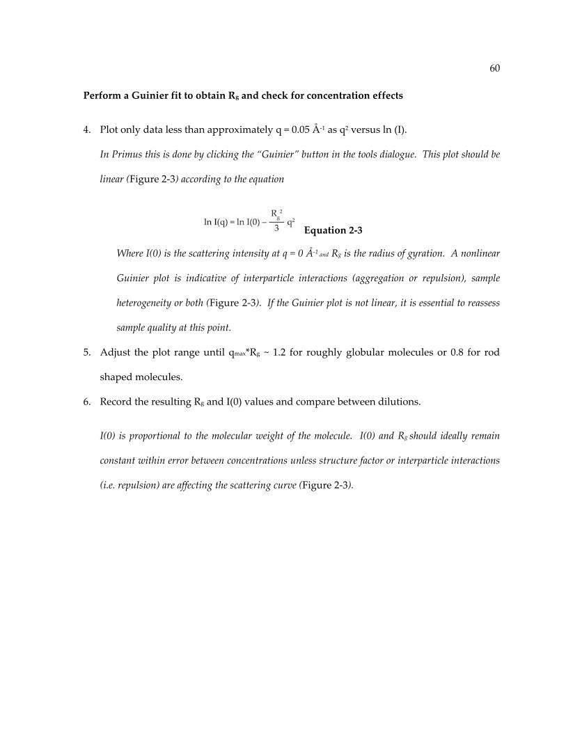
60
Perform a Guinier fit to obtain Rg and check for concentration effects
4. Plot only data less than approximately q = 0.05 Å‐1 as q2 versus ln (I).
In Primus this is done by clicking the “Guinier” button in the tools dialogue. This plot should be
linear (Figure 2‐3) according to the equation
Equation 2‐3
Where I(0) is the scattering intensity at q = 0 Å‐1 and Rg is the radius of gyration. A nonlinear
Guinier plot is indicative of interparticle interactions (aggregation or repulsion), sample
heterogeneity or both (Figure 2‐3). If the Guinier plot is not linear, it is essential to reassess
sample quality at this point.
5. Adjust the plot range until qmax*Rg ~ 1.2 for roughly globular molecules or 0.8 for rod
shaped molecules.
6. Record the resulting Rg and I(0) values and compare between dilutions.
I(0) is proportional to the molecular weight of the molecule. I(0) and Rg should ideally remain
constant within error between concentrations unless structure factor or interparticle interactions
(i.e. repulsion) are affecting the scattering curve (Figure 2‐3).

61
Figure 2‐3. Guinier analysis.
Guinier plot of an aggregated protein (black diamonds), an RNA with interparticle repulsion
(gray triangles) or an RNA sample of good quality (gray squares) (see Section 2.3.3).

62
Determine the general conformation of the molecule using a Kratky plot
7. Plot q versus q2I in the range q < 0.4 Å‐1.
In version 2.3 or older, click Sasplot and then select View Y*X2 : X. In version 2.4, select
plots, then Kratky plot.
8. Examine the plot: Compact molecules (rod‐shaped or globular) will display one peak
(Figure 2‐4), extended molecules will display a peak with a shoulder (Figure 2‐4), and
unfolded molecules will increase continuously with no peak.
Extrapolate an idealized curve at zero concentration
9. In Primus, load all background subtracted curves in the dilution series.
10. Enter the concentration of each dilution (see steps 24 and 26 of Section 2.3.1).
11. Plot only the portion of the curve that has exact overlap between the different
concentrations.
This will likely exclude approximately q < 0.05‐0.10 Å‐1 and q > 0.40 Å‐1.
12. Calculate a theoretical curve with no concentration dependence by clicking “Zeroconc.”
Frequently, RNA experiences interparticle repulsion that manifests as inconsistent values of I(0)
and Rg for different dilutions. This step will remove contributions from repulsion. Note: this
feature is not available in the 64‐bit version for Windows.
13. Alternatively, merge the small angles (q < 0.4 Å‐1) of a low concentration data set with
the wider angles (0.35 < q < 2 Å‐1) of a high concentration data set.
This method is preferable if aggregation is a problem at higher concentrations.

63
Figure 2‐4. Kratky analysis.
Kratky plot of three different RNA molecules with unique global folds (see Section 2.3.3).

64
Determine the pair‐distance distribution function (PDDF)
14. Load the highest quality buffer subtracted scattering curve or the zero concentration
extrapolated curve (steps 10‐14) in Primus. Remove all data points at q > 0.30‐0.33 Å‐1.
The range of data used at this step will depend on the signal to noise ratio at larger values of q.
Exclude the noisiest data by decreasing the maximum q value.
15. Click Gnom (32‐bit version) or Tools Distance distribution (64‐bit version)
16. Estimate the maximum dimension of the particle (Dmax or Rmax). 3*Rg is a good place to
start. Do not restrain P(Rmax) = 0 to start. Click “run”.
17. Examine the resulting fit to the scattering curve.
Ensure that there are no excessive oscillations in the predicted curve due to over‐fitting noise at
larger q values. Also, zoom in to ensure that the predicted curve fits the experimental data well
at small values of q. Poor fitting in this region can indicate an incorrect Dmax or contributions
from interparticle interactions.
18. Examine the resulting PDDF.
The PDDF should fall off smoothly at large values of “r” toward zero. Notice where the p(r)
curve becomes constant and choose this as a new Dmax value. If the curve does not level off at
larger values of r, try increasing Dmax.
19. Repeat steps 17‐19; however, this time use the newly determined Dmax value and restrain
P(Rmax) = 0.
20. Adjust Dmax in increments of 1‐2 Å until the curve falls smoothly to zero and does not
sample any negative values (Figure 2‐5).
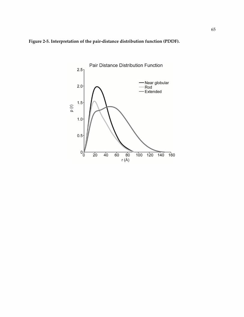
65
Figure 2‐5. Interpretation of the pair‐distance distribution function (PDDF).

66
Generate ab initio models
21. Using the output file generated by steps 15‐21 (will be a “.out” file), run DAMMIF 10‐20
times using parameters appropriate for your molecule (see introduction above).
22. Move the resulting ab initio models (*‐1.pdb files) to a new directory. Navigate to this
directory.
23. Type the command damaver /a.
This will run the DAMAVER suite of programs to average and filter the ab initio models. In
Windows, the folder containing DAMAVER must be specified before the command.
24. Examine the DAMAVER output file “damsel.log”.
This log file contains the normalized spatial discrepancy (NSD) values for each pair of models.
The NSD is a measure of similarity between a set of points (in this case the ab initio models). In
general, the mean NSD (NMSD) tends toward 0 for highly similar objects and exceeds 1 for
systematically different objects [181]. For SAXS models, the NMSD should fall between 0.7‐0.9
for a unique solution to the scattering curve. An NMSD larger than 0.9 could be indicative of
many things, including sample heterogeneity or a high degree of flexibility.
25. Examine the resulting averaged, filtered model (damfilt.pdb) using a molecular model
visualization program such as Pymol and compare it to any existing structures of
relevant domains or homology models.
26. (Optional) Overlay all‐atom models with the average ab initio model using the
Supcomb20 algorithm (ATSAS software) [181].

67
Figure 2‐6. Ab initio modeling.
Ab initio structure (gray spheres) of a 28.2 KDa RNA: RNA complex with the jointly refined
NMR/SAXS structure (dark gray) [176] superimposed using the Supcomb20 algorithm [181].

68
2.4 Discussion
2.4.1 Background
Development of SAXS instrumentation and technology
Characterization of macromolecules by small angle scattering gained traction in the
1970s with studies of the ribosome in solution using neutron scattering (SANS) [182]. The first
RNA molecules analyzed by SAXS were tRNAs from yeast [183] and E. coli [184]; however,
characterization was limited to inference of size and shape features from the scattering curve.
The development of SAXS instrumentation leapt forward dramatically as synchrotron X‐ray
sources became more widely available starting in the late 80s. In the late 90s, computational
abilities caught up with SAXS instrumentation and some of the first low resolution models
determined by small angle scattering were obtained of the ribosome [185]. The biological small
angle scattering group led by Dmitri Svergun at EMBL‐Hamburg has drastically improved the
availability of software for processing and analyzing SAXS, expanding the accessibility of this
method for new users.
Application of SAXS characterization to nucleic acids
In recent years, characterization of biomolecules by SAXS has become increasingly
popular. Due to heightened interest, SAXS has become more accessible both in terms of
instrumentation and the availability of software for data processing and analysis. SAXS is a
versatile technique and has been used to study RNA folding of complex molecules such as
RNase P [168] and the Tetrahymena ribozyme [186] and to characterize the free and bound
conformations of several riboswitches [143‐147, 187]. The combination of NMR and SAXS has
been used to characterize the structure of the turnip crinkle virus ribosome binding element
69
[141] and the U2/U6 snRNA complex [95], which is a part of the active spliceosome. A few
nucleic acid‐protein complexes, such as the ribosome (see above) and the picoRNA viral
replication complex [188], have also been characterized by SAXS and/or SANS.
Beyond low resolution characterization
Although SAXS provides low resolution structural information, in many cases this is
enough to infer important information about the structure of nucleic acids. Cryo‐electron
microscopy (cryo‐EM) and tomography (cryo‐ET) also provide a similar level of resolution to
SAXS; however, SAXS has some advantages over these methods. First, SAXS is applicable to
much smaller molecules and complexes than cryo‐EM/T, which makes it more compatible with
NMR. Second, SAXS can provide more information about highly flexible or unfolded
molecules. Single molecule cryo‐EM studies rely on averaging many molecules with the same
properties to achieve sufficient signal. In highly flexible molecules, this averaging leads to loss
of information in flexible regions [189]. Cryo‐ET studies combine images of different
orientations of a molecule, resulting in a three‐dimensional “snapshot”, and may be more
appropriate for heterogeneous samples [190]. SAXS retains information about all possible
orientations and conformations of a molecule in solution. If an adequate diversity of models
can be generated, SAXS can be used to extract an ensemble of models that represents the range
of conformational diversity in solution.
Molecular modeling and molecular dynamics simulations are important tools for
generating all‐atom structural models in conjunction with SAXS. Nucleic acids are well‐suited
for all‐atom modeling due to the consistency of the basic helical structural unit between
sequences. Knowledge of secondary structure is required, but can be determined by a number

70
of methods (see Section 2.2.5). Long‐range contacts, such as pseudoknots and tetraloop‐
receptor interactions, can also be predicted through bioinformatics and biochemical methods
[165]. Modeling software employs either a fragment‐based approach [162] or coarse‐grained
approach [191, 192]. Homology modeling is also a good choice when the structure of a similar
molecule is already known [140]. A potentially challenging step in modeling nucleic acid
structure is adequate sampling of conformational space. This can be achieved using molecular
dynamics simulations [168] or normal mode analysis on a server like elNémo [193].
Once a large array of models has been generated, models can be filtered against
experimental scattering data. The SAXS curve of a model is predicted by summing all existing
atom pair‐distances using the Debye equation:
Equation 2‐4
Where dij is the distance between atoms i and j, N is the number of atoms in the molecule and
f(q) is the form factor for a type of atom. While this is a computationally intensive process,
several web‐based software tools approximate the form factor for a group of atoms and are
appropriate for nucleic acids, such as FAST‐SAXS RNA [194] and the FoXS server [195].
Ensembles of models can also be fit to the experimental SAXS curve using multiple ensemble
simulation [150] or ensemble optimization methods [149]. Ensemble modeling is especially
powerful for characterizing dynamics that may be functionally important
2.4.2 Critical parameters and troubleshooting
Of utmost importance is sample preparation and quality. Nucleic acid samples must be
as homogeneous as possible and free of degradation. Additionally, buffer matching and
concentration determination must be as accurate as possible (see Section 2.3.1). Because nucleic

71
acids are often soluble even when misfolded or aggregated and because SAXS is a low
resolution method, issues in sample preparation may not be evident until far into the data
analysis process. This problem is compounded by the fact that SAXS data processing is a
complex and non‐linear process that often requires optimization of several different parameters.
Therefore, it is essential to assay sample quality as much as possible by denaturing and non‐
denaturing PAGE, size exclusion chromatography, dynamic light scattering and, if possible,
sample specific activity assays. Standard samples, such as lysozyme or a well characterized
RNA [176], are also very important (see Section 2.3.2). Standards should be characterized at
minimum every time the SAXS instrument is rearranged, which is often every data collection at
a synchrotron X‐ray source and intermittently at a bench top source. Frequent characterization
of standard samples will increase the chances of detecting issues in detector image processing,
calibration and data reduction.
Sometimes, even when sample preparation and data processing are performed correctly,
it is not possible to obtain a good quality, unique ab initio model [139]. In this situation, the
nucleic acid may be very flexible or poorly structured. As described above, ensemble modeling
may be one possible route for a flexible nucleic acid. Alternatively, construct design may also
be reconsidered. Nucleic acid structure can be drastically altered by small changes in sequence
or truncations of important sequence. For instance, often two guanosine residues are
incorporated at the 5’ end of an RNA sequence for transcription with T7 RNA polymerase. If
these residues are non‐native, use of a hammerhead ribozyme at the 5’ end [196] may be
considered to generate fully native sequence. A hammerhead ribozyme downstream of the
transcript will resolve 3’ end heterogeneity, which is useful when single nucleotide resolution
purification is challenging (e.g. transcripts > 80 nt) [197].

72
2.4.3 Time considerations
Up to 1 month should be allowed for sample preparation. Ideally, size exclusion
chromatography and dialysis should be performed immediately before data collection. Data
acquisition times vary widely depending on the X‐ray source. Typical synchrotron data
collection for several samples may take 1 or 2 days including instrument setup. Bench top data
collection times are up to 24 hours per sample depending on concentration and the stability of
the sample. Initial data processing should be performed concomitantly with data acquisition to
ascertain sample quality and whether additional dilution points are necessary. The time
required for data processing and ab initio modeling is highly variable and can take from a week
to a month depending on the properties of the nucleic acid.

73
Chapter 3: Structure of the yeast U2/U6 snRNA complex
The majority of the work presented in this chapter is published in the following form:
Jordan E. Burke, Dipali G. Sashital, Xiaobing Zuo, Yun‐Xing Wang, and Samuel E. Butcher.
2012. Structure of the yeast U2/U6 snRNA complex. RNA 18(4): 673‐83.
D.G.S collected data for the Helix I structure and assisted with construct design.
X.Z. and Y.W. provided technical assistance for measurement of SAXS data and structure calculations.
74
3.1 Abstract
The U2/U6 snRNA complex is a conserved and essential component of the active
spliceosome that interacts with the pre‐mRNA substrate and essential protein splicing factors to
promote splicing catalysis. Here we have elucidated the solution structure of a 111 nucleotide
U2/U6 complex utilizing an approach that integrates SAXS, NMR and molecular modeling. The
U2/U6 structure contains a three‐helix junction that forms an extended “Y” shape. The U6
internal stem‐loop (ISL) forms a continuous stack with U2/U6 Helices Ib, Ia and III. The coaxial
stacking of Helix Ib on the U6 ISL is a configuration that is similar to the Domain V structure in
group II introns. Interestingly, essential features of the complex – including the U80 metal
binding site, AGC triad and pre‐mRNA recognition sites – localize to one face of the molecule.
This observation suggests that the U2/U6 structure is well‐suited for orienting substrate and
cofactors during splicing catalysis.

75
3.2 Introduction
Pre‐mRNA splicing, the removal of introns from pre‐mRNA, is an essential process in all
eukaryotes [28, 90, 198] that proceeds through two transesterification reactions [199]. The
spliceosome is responsible for pre‐mRNA splicing and is composed of a large number of
proteins and 5 small nuclear RNAs (snRNAs): U1, U2, U4, U5 and U6 [3, 200]. At the heart of
the spliceosome is the U2/U6 snRNA complex [23‐25, 201‐203], an essential component of the
active site of the spliceosome.
The spliceosome has been hypothesized to be a ribozyme [94, 204] based on mechanistic
and structural similarities with the group II self‐splicing intron [205, 206] and the observation
that protein‐free U2/U6 complexes derived from the human sequences have residual catalytic
activity related to splicing in vitro [105, 207, 208]. These complexes promote inefficient reactions
that are chemically similar to the first step of splicing [209] and a complete, two‐step trans‐
splicing reaction [104]. The catalytic activity of the complex is dependent on the presence of
Mg2+ [104, 210]. U2/U6 specifically binds divalent metal ions in vitro in the context of assembled
spliceosomes in the U6 internal stem‐loop (ISL) [59, 62] and the AGC triad [104] in U2/U6 Helix
Ib (Figure 3‐1), suggesting a possible two‐metal ion mechanism [211] for splicing catalysis
similar to the proposed mechanism of the group II self‐splicing intron [103, 212, 213].
The yeast U2/U6 complex has been proposed to form a three‐helix junction (Figure 3‐1)
flanked by a series of short helical segments connected by internal loops and bulges [23]. The
three‐helix junction is made up of the U6 internal stem‐loop (ISL) and U2/U6 intermolecular
Helices I and II and is linked by a uracil‐rich loop (Figure 3‐1) [23]. The U6 ISL is highly
conserved [37, 58] and contains an essential metal binding site at U80 (Figure 3‐1) [59, 101, 104,
76
214]. Helix I is essential for splicing [23] and contains the invariant AGC triad. Base‐pairing in
Helix Ib (Figure 3‐1) between the AGC triad and U2 is important for both steps of splicing [97,
98]. The internal loop between Helix I and Helix III is composed of essential motifs in U6 and
U2 that base‐pair to the 5’ splice site and the branchpoint of the pre‐mRNA substrate,
respectively, to promote the first step of splicing (Figure 3‐1) [68]. This loop is closed by a third
intermolecular helix (Helix III), which has been detected in vivo in mammalian cells (Figure 3‐1)
[25]. While genetic evidence suggests formation of a three‐helix junction in U2/U6, NMR
studies of several truncated versions of the U2/U6 complex [96] demonstrated formation of a
four‐helix junction conformation. A statistical mechanical analysis of the U2/U6 free energy
landscape predicted that the three‐helix junction secondary structure has a more favorable free
energy, but that the four‐helix junction conformation would dominate in the presence of
favorable coaxial stacking interactions [100]. MFOLD [161] predicts four different secondary
structures for the yeast U2/U6 complex that have very similar free energies (‐34.4 ≤ ΔG ≤ ‐33.1).
Therefore, identification of the correct secondary structure from predicted structures is highly
challenging in the absence of direct experimental data.
Very little is known about the tertiary structure of the U2/U6 complex. Structural studies
of the U6 ISL by NMR [59, 61] reveal that the ISL contains a 3‐nucleotide internal loop
containing a conserved metal binding site at the phosphate of U80. The base of U80 stacks into
the helix in the presence of divalent metal ions [214]. This conformation involves formation of a
highly dynamic C67‐U80 pair that is modulated by the protonation state of A79, which can form
a competing C67‐A79 base‐pair [61]. Additionally, hydroxyl radical experiments indicate that
U80 is proximal to the 5’ splice site in the spliceosome [215]. Helix I has also been proposed to
interact with the 5’ splice site [216]. Crosslinking studies have revealed possible contacts

77
between the pre‐mRNA binding site and the UA bulge of Helix I as well as U‐rich sequences
within the three‐helix junction (Figure 3‐1) [216‐218]. Additionally, single molecule FRET
studies have demonstrated that the pentaloop of the U6 ISL and Helix III are distal in the
presence of Mg2+ [219].
Due to apparent structural and mechanistic similarities between the spliceosome and the
group II self‐splicing intron [205], a tertiary structure model has been proposed for U2/U6 that
infers long‐range contacts based on those present in the crystal‐structure of the group II intron
[206]. In the proposed model, two base‐triples form a metal binding platform that constitutes
the active site [206, 212]. The base‐triples are formed through interaction of U80 in the U6 ISL
and a residue in the 5’ splice site recognition sequence with the major groove of Helix Ib. A
recent study demonstrated that the first step of the group II intron reaction is more efficient in
the presence of a linking oligonucleotide that holds the branch site and the 5’ splice site in close
proximity, similar to the function of U2/U6 Helix III [220]. Still, it remains unclear how all of
these elements function together during the splicing reaction.
Here we present the structure of a 111‐nucleotide U2/U6 snRNA complex in solution as
analyzed by small angle X‐ray scattering (SAXS) and NMR. We employed a novel method in
which a large number of starting structural models generated with MC‐Sym [162] were sorted
by agreement with the experimental NMR and SAXS data. The structural models in best
agreement with both data sets were jointly refined against SAXS and NMR data by restrained
molecular dynamics and energy minimization.

78
Figure 3‐1. Proposed secondary structure of a 111 nt RNA.
Based on the S. cerevisiae U2/U6 RNA complex [23]. Structural features are color coded as
follows: Helix I (green), Helix II (purple), Helix III and an internal loop that binds to 5’ splice
site and branchpoint (orange), U6 ISL (blue), U‐rich loop (dark gray) and non‐native sequences
(light gray). Experimentally determined base‐pairs are shown as black lines or circles (see
Figure 3‐4).

79
3.3 Materials and Methods
3.3.1 RNA sample preparation
RNA was transcribed in vitro using purified His6‐tagged T7 RNA polymerase. DNA
templates were prepared through phosphorylation and ligation of short complementary,
overlapping oligonucleotides (Integrated DNA Technologies) into pUC19 vector (New England
Biolabs). A BsaI restriction site was included at the end of the template to allow for run‐off
transcription after digestion with BsaI enzyme (NEB). 13C‐15N labeled samples of U2/U6 were
prepared using 13C‐15N labeled nucleotides (Cambridge Isotope Laboratories). RNA samples
were purified using denaturing 8% PAGE with 8 M urea. Impurities were removed by DEAE
anion‐exchange (Biorad) using a low salt buffer (20 mM Tris‐HCl, pH 7.6, 200 mM sodium
chloride) to wash and a high salt buffer (20 mM Tris‐HCl, pH 7.6, 1.5 M sodium chloride) to
elute the RNA. Samples were then ethanol precipitated and resuspended at a concentration of <
5 mg/ml. The RNA was re‐folded by heating to 90oC and cooling quickly on ice and samples
were dialyzed for 16‐24 h in 10 mM potassium phosphate, pH 7.0 in 0 or 2 mM magnesium
chloride (NMR samples) or 50 mM Tris‐HCl, pH 7.0, 150 mM sodium chloride and 0, 2 or 10
mM magnesium chloride (SAXS samples). All samples were assayed for folding homogeneity
by 6% non‐denaturing PAGE.
3.3.2 NMR data collection
All spectra were obtained on Bruker Avance or Varian Inova spectrometers equipped
with cryogenic single z‐axis gradient HCN probes at the National Magnetic Resonance Facility
at Madison. Resonances were assigned using 1H‐1H 2D NOESY with a mixing time of 100 ms
and 1H‐15N 2D TROSY‐HSQC experiments and by reference to previously determined chemical

80
shifts for helical domains (BMRB entry 6320 and 17972). Partial alignment for RDC
measurements was achieved by addition of 10 mg/ml Pf1 filamentous bacteriophage (ASLA) to
a 13C, 15N G and U labeled sample. Pf1 phage concentration was confirmed by measuring 2H
splitting at 700 MHz. Imino 1H RDC measurements were obtained using a 1H‐15N TROSY‐HSQC
experiment. RDC measurements were in the range of ‐8.0 to +26.4 Hz.
3.3.3 SAXS data collection
All SAXS data were obtained at Sector 12 of the Advanced Photon Source at Argonne
National Laboratory. Measurements were carried out in 50 mM Tris, pH 7.0, 150 mM sodium
chloride and 0 mM, 2 mM or 10 mM magnesium chloride. RNA samples were loaded into a 1
mm capillary and flowed back and forth throughout the exposure. 20 data collections of 0.5
seconds each were averaged for each sample and buffer. The scattering intensity was obtained
by subtracting the background scattering from the sample scattering. Buffer matching was
determined by adjusting subtraction of wide angle scattering (WAXS) until contribution from
buffer scattering was negligible. The scattering intensity at q = 0 Å‐1 (I(0)), as determined by
Guinier analysis, was compared between four different concentrations (0.5, 1.0, 2.0, and 3.0
mg/ml) to detect possible interparticle interactions. WAXS and SAXS data were merged using
the region between q = 0.09 Å‐1 and 0.17 Å‐1. Samples were assayed for radiation damage by
denaturing 8% PAGE after data collection. No radiation damage was detected (data not
shown).
3.3.4 Ab initio structure calculation
SAXS data were processed using GNOM [160] to obtain the pair‐distance distribution
function (PDDF) and extrapolate the scattering curve to I(0). Dmax was calibrated in increments
81
of 2 Å until the PDDF curve fell smoothly to zero. The GNOM output was then used with
DAMMIF [179] to calculate 20 dummy atom models. Models were averaged using the program
DAMAVER [221], with a resulting normalized spatial discrepancy (NSD) of between 0.7 and 0.9
indicating good agreement between individual models. Finally, smooth envelope models were
generated using the SITUS software [222]. Ab initio structures were superimposed using the
Supcomb program [181].
3.3.5 Molecular modeling and refinement
Three‐dimensional models of each isolated helix and stem‐loop in U2/U6 consistent with
the NMR‐determined secondary structure were created using the MC‐Fold/MC‐Sym pipeline
[162]. The three‐helix junction was generated in three steps using the relation capabilities of
MC‐Sym [223]. Helices were then built onto the junction region in MC‐Sym. The X‐ray
scattering amplitudes of 2500 of the models were predicted using the FoXS web server [195].
Agreement to the experimental SAXS amplitudes was measured using χ2 goodness of fit
analysis. All but the 25% of models with the lowest χ2 values were discarded. The best models
were sorted by fit to 18 experimental RDC measurements from imino 1H‐15N couplings as
determined using the PALES/DC software [224]. The models with a Q factor of less than 0.35
were chosen for further refinement. Covalent connectivity was restored for these 10 models
using the AMBER force field (Open MM Zephyr software) [225]. Normal mode analysis was
performed for all ten models as previously described [139] using the elNémo server [193]. The
resulting perturbed models were sorted again as described above. The selected models were
then refined against SAXS data, RDC measurements and base‐pairing restraints in XPLOR‐NIH
as previously described [141]. Distance restraints based on the previously determined U6 ISL
structure [61] were incorporated on the basis of chemical shift similarity between the U6 ISL

82
construct and the 111 nt U2/U6 construct. Distance and dihedral angle restraints based on A‐
form helical geometry were incorporated for Helices I, II and III. P‐P distances (5.4 ± 0.5 Å)
were included for single stranded regions to help maintain pseudo A‐form geometry and
prevent the backbone phosphate groups from moving too close during molecular dynamics
simulations in the absence of other restraints. P‐P envelope size restraints were also
incorporated based on the overall size of the ab initio structure.
3.4 Results
3.4.1 Global Structure of the S. cerevisiae U2/U6 complex
To investigate the structure of the U2/U6 complex, we utilized a 111 nt RNA construct
(hereafter referred to as U2/U6) that contains the entire base‐paired region of the S. cerevisiae
U2/U6 snRNA complex linked by a UUCG tetraloop on Helix II to ensure proper stoichiometry
of the U2 and U6 strands (Figure 3‐1). The global fold of U2/U6 in 150 mM NaCl and in the
presence and absence of MgCl2 was determined by small angle X‐ray scattering (SAXS). The
Kratky profile exhibits two peaks, which are indicative of a well‐defined, non‐globular
conformation (Figure 3‐2A). The PDDF (Figure 3‐2B) exhibits a peak at 20 Å that corresponds to
A‐form helical width and another at 40 Å that may correspond to helical length. The structure
of the U6 ISL is 40 Å in length [61] and a model of Helix II generated using the MC‐Fold/MC‐
Sym pipeline [162] measures 44 Å in length. Both features are still visible in the PDDF plot
upon addition of 2 mM MgCl2; however, the increase in the peak intensity at 20 Å (Figure 3‐2B)
likely results from helical stabilization by Mg2+. In 150 mM NaCl, the radius of gyration (Rg) of
the U2/U6 RNA is 37 Å and the maximum dimension (Dmax) is 120 Å. Upon addition of 2 mM
MgCl2, the Rg and Dmax are slightly smaller – 34 Å and 117 Å respectively (Table 3‐1) – indicating
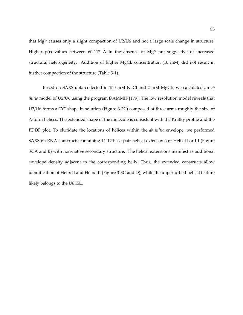
83
that Mg2+ causes only a slight compaction of U2/U6 and not a large scale change in structure.
Higher p(r) values between 60‐117 Å in the absence of Mg2+ are suggestive of increased
structural heterogeneity. Addition of higher MgCl2 concentration (10 mM) did not result in
further compaction of the structure (Table 3‐1).
Based on SAXS data collected in 150 mM NaCl and 2 mM MgCl2, we calculated an ab
initio model of U2/U6 using the program DAMMIF [179]. The low resolution model reveals that
U2/U6 forms a “Y” shape in solution (Figure 3‐2C) composed of three arms roughly the size of
A‐form helices. The extended shape of the molecule is consistent with the Kratky profile and the
PDDF plot. To elucidate the locations of helices within the ab initio envelope, we performed
SAXS on RNA constructs containing 11‐12 base‐pair helical extensions of Helix II or III (Figure
3‐3A and B) with non‐native secondary structure. The helical extensions manifest as additional
envelope density adjacent to the corresponding helix. Thus, the extended constructs allow
identification of Helix II and Helix III (Figure 3‐3C and D), while the unperturbed helical feature
likely belongs to the U6 ISL.

84
Figure 3‐2. Small angle X‐ray scattering of U2/U6.
A. Kratky profile of the U2/U6 complex in the absence and presence of Mg2+. All experiments
were conducted in 50 mM Tris, pH 7.0, 150 mM NaCl and 0 or 2 mM MgCl2. B. Pair‐distance
distribution function plot of U2/U6 in the absence and presence of magnesium chloride. C. Ab
initio structure of U2/U6 in 2 mM MgCl2. 20 structures were generated using the program
DAMMIF and then averaged with DAMAVER, yielding a normalized spatial discrepancy
(NSD) of 0.85.

85
Table 3‐1. SAXS measurements of the 111 nt U2/U6 RNA.
Condition Rg (Å) Dmax (Å)
No Mg2+ 37.3 120
2 mM Mg2+ 34.0 117
10 mM Mg2+ 35.6 118

86
Figure 3‐3. Identification of helices within the U2/U6 envelope.
Helical extensions of 11 base‐pairs on Helix II (A, in red) or 12 base‐pairs on Helix III (B, in blue)
were added to the original 111 nt RNA. Lengths of the helical extensions were estimated based
on 3D models generated using the MC‐Fold/MC‐Sym pipeline [162]. The ab initio model
containing extended Helix II is shown in red (C) and the model containing extended Helix III is
shown in blue (D) with the original RNA shown in gray.
87
3.4.2 UV and NMR Spectroscopy of U2/U6 RNA
NMR spectroscopy was used to investigate the 111 nt U2/U6 RNA structure in 10 mM
potassium phosphate, pH 7.0, with and without 2 mM MgCl2. Secondary structure was
determined by 2D 1H‐1H NOESY (Figure 3‐4) and 1H‐15N TROSY‐HSQC (Figure 3‐5A).
Addition of 2 mM MgCl2 does not change the secondary structure of the molecule as evidenced
by 2D 1H‐1H NOESY and 1H‐15N TROSY‐HSQC (data not shown). In addition, the secondary
structure of a bimolecular U2/U6 complex lacking the UUCG tetraloop linker in 10 mM K+PO4‐
pH 7.0, and 100 mM KCl is consistent with the structure of the linked RNA construct (Figure
3‐6), demonstrating that the presence of the linker and changes in monovalent salt conditions
do not influence the structure of the complex.
Nearly all base‐paired imino resonances in the RNA could be assigned (Figure 3‐4), with
the exception of those that are at effective helical ends and exchange rapidly with solvent. The
U6 ISL and Helix I were assigned based on chemical shift similarity with previously determined
structures of the isolated U6 ISL domain [59] and a 24 nt Helix I construct (Chapter 4, PDB ID
2LK3), respectively. Sequential NOEs indicate formation of Helix III, Helix Ia, the U6 ISL and
Helix II (Figure 3‐4). Imino resonances were unambiguously assigned based on 1H‐1H NOESY
and 1H‐15N TROSY‐HSQC experiments, with the exception of two G imino resonances. These
resonances have hydrogen bonded 1H and 15N chemical shifts indicative of Watson‐Crick base‐
pairing (Figure 3‐5A), although any potential NOE between them is obscured by the diagonal
due to their similar 1H chemical shifts. However, the only remaining unassigned helical G
imino protons belong to U2‐G21 and U6‐G60 in Helix Ib, so by process of elimination we can
tentatively assign these resonances to U2‐G21 and U6‐G60 in Helix Ib. These assignments are

88
also consistent with the chemical shifts of these imino protons in the isolated Helix I RNA
(Chapter 4, BMRB code 17972).
The chemical shifts of the U6 ISL within U2/U6 are identical to those previously
determined for the isolated U6 ISL (Figure 3‐5B) [59, 61], indicating that the U6 ISL is folded in
an identical manner to the previously determined structure and further suggesting that it does
not participate in stable tertiary contacts. All of the base‐pairs in Helix II are observed with the
exception of the last C‐G pair (Figure 3‐4). The adjacent uracil nucleotides (U2:U16‐19 and
U6:U87‐90) have resonances that are observable in the 1D 1H NMR spectrum (Figure 3‐4) and
also in the 1H‐15N TROSY‐HSQC (Figure 3‐5A); however, these resonances are not visible in the
NOESY spectrum indicating that they exchange with water during the 100 ms mixing time.
Therefore, these uracil residues are not involved in stable base‐pair interactions but may
interact transiently with each other, consistent with their chemical shifts which are diagnostic
for U‐U wobble pairs [226, 227]. Transient formation of such pairs across the U‐rich loop may
effectively extend Helix II (Figure 3‐1, see Chapter 5 for more details).
Base‐pairing is also observed throughout Helix III (Figure 3‐4). Observation of the NOE
cross‐peak between U2‐U40 and U2‐U42 (Figure 3‐4) indicates that U2‐C41 is flipped out of the
helix, allowing the flanking base‐pairs to stack. There are no observable imino protons
corresponding to the large internal loop containing the 5’ splice site and branchpoint
recognition sequences (Figure 3‐1 and Figure 3‐5A). Therefore, stable base‐pairing interactions
involving imino protons do not form across this loop.
U2/U6 denatures in two cooperative transitions at 42°C and 72°C (Figure 3‐7B). Because
the second transition occurs near the temperature limit of this method, we repeated the

89
experiment in 3M urea to detect highly stable secondary structure; however, no additional
melting transitions were observed (data not shown). Observation of base‐pairs by 1D 1H NMR
indicated that the first transition consists of denaturation of Helix III and Helix I while the
second transition consists of denaturation of the U6 ISL and Helix II (data not shown).
Interestingly, truncation of Helix III (Figure 3‐7C) and addition of a GC pair increases the
melting temperature of Helix I and III to 48°C and the melting temperature of either Helix II or
the U6 ISL to 79°C, resulting in a non‐cooperative upper transition (Figure 3‐7B). Complete loss
of Helix III (Figure 3‐7C) results in one cooperative transition centered at 49°C for Helices I and
II and the U6 ISL (Figure 3‐7B). All three constructs have the same hyperchromicity (Figure
3‐7A), indicating that the extent of base‐pairing is unchanged by truncation of Helix III.

90
Figure 3‐4. Secondary structure of a 111 nt U2/U6 RNA as determined by NMR.
1D 1H spectrum and 2D 1H‐1H NOESY of the U2/U6 complex in 20 mM potassium phosphate,
pH 7.0. Assignments and connecting lines are color‐coded according to secondary structure as
in Figure 3‐1. The NOE peak between U2‐U12 and U2‐G13 is only visible at a lower contour
level and is therefore indicated with a dashed circle. Base‐pairs confirmed by 1H‐1H 2D NOESY
are indicated in Figure 3‐1 by black lines or circles, while base‐pairs inferred by chemical shift
agreement are indicated with gray lines.

91
Figure 3‐5. 1H and 15N imino chemical shift assignments for U2/U6.
A. 1H‐15N TROSY‐HSQC experiment in 10 mM potassium phosphate, pH 7.0. Labels are color
coded according to secondary structure as follows: Helix I (green), Helix II (purple), Helix III
(orange), U6 ISL (blue) and linker sequences (black). B. Agreement between chemical shifts for
the U6 ISL (blue) [61] and the 111 nt U2/U6 RNA (dark gray). Labels are connected to both
peaks for each residue by black lines, except for G62 (*) which is not present in U2/U6. All
chemical shifts are identical with the exception U70 which is adjacent to the pentaloop and is
highly sensitive to salt conditions.

92
Figure 3‐6. Secondary structure bimolecular U2/U6 construct.
A. Secondary structure of the bimolecular U2/U6 construct as determined by NMR. Color
coding is according to structure as in Figure 3‐1. B. 1H 1D and 1H‐1H 2D NOESY of the
bimolecular U2/U6 RNA. Lines and resonance assignments are color‐coded according to
secondary structure as in A.

93
Figure 3‐7. Hyperchromicity and thermodynamic stability of the U2/U6 complex.
A. Hyperchromicity of various RNA constructs composed of sequences from the S. cerevisiae
U2/U6 complex. B. First derivative plots of the hyperchromicity data in (A). C. Length of Helix I
and Helix III in each of the U2/U6 RNAs. All of the U6 ISL and Helix II are also present in these
constructs (not shown). RNA sequence is color coded as in Figure 3‐1.

94
3.4.3 Modeling the structure of the U2/U6 snRNA complex in solution
We used a unique methodology that incorporates data from SAXS and NMR to solve the
all‐atom structure of the U2/U6 complex (Figure 3‐8). All‐atom structural models of U2/U6 were
generated using MC‐Sym [162] based on the secondary structure determined by NMR. 2500
models were filtered based on goodness of fit (χ2 agreement) between the predicted small angle
X‐ray scattering amplitudes for each model and the experimental data (Figure 3‐9A). The 25% of
structures with the best χ2 values (less than 2.57) were then tested for agreement with 1H‐15N
RDC measurements. Only those models with a Q factor [228] of less than 0.35 were accepted
(Table 3‐2), resulting in 10 structural models that fit well to both SAXS and NMR data (Figure
3‐9A and B).
The 10 selected models were then subjected to normal mode analysis (NMA) as
previously described [139] to ensure that conformational space has been adequately sampled
and that the models were not trapped in a local energetic minimum. Comparison of the
predicted scattering curves of the states obtained from NMA with experimental SAXS data
resulted in re‐selection of the original states, leading to the conclusion that the originally
selected models reflect the true ground state conformation of U2/U6 (data not shown). Finally,
the 10 structural models were refined simultaneously against SAXS and RDC measurements
using restrained molecular dynamics and energy minimization in XPLOR‐NIH as previously
described [141].
The final structures display excellent agreement between the predicted scattering
profiles of the models and the experimental data (Figure 3‐9C), with a goodness of fit χ 2 value
of less than 0.94 (Table 3‐2). Additionally, there is excellent agreement between the predicted
and observed RDC measurements (Figure 3‐9D) with Q factor values of 0.12 or less (Table 3‐2).

95
The 10 lowest energy structures have a global backbone RMSD of 2.1 Å (Table 3‐3). All
individual A‐form regions have RMSD values of 0.9‐1.7 Å, while single stranded regions have
higher RMSD values of 2.5‐3.0 Å (Table 3‐3).
The conformation of the refined structural models of U2/U6 is entirely consistent with
the ab initio model generated from SAXS data alone (Figure 3‐10A), and our independent SAXS
analysis of the extended constructs corroborates the positioning of the helices around the three‐
helix junction (Figure 3‐3). The U6 ISL, Helix I and Helix III form a continuous stack (Figure
3‐10B) resulting in a large distance between the pentaloop of the U6 ISL and 5’ end of Helix III
(~65 Å) that is consistent with single‐molecule FRET studies of the U2/U6 complex [219]. The
unpaired uracil residues in the junction region are close enough to form transient interactions
such as U‐U wobble pairs, which would be consistent with the peaks observed in the 2D 1H‐15N
TROSY‐HSQC (Figure 3‐5A) and the ~20 Å width of the SAXS envelope in this region.
However, the uracil residues in the linker were left unrestrained in the structural models and
therefore appear disordered in the structure.
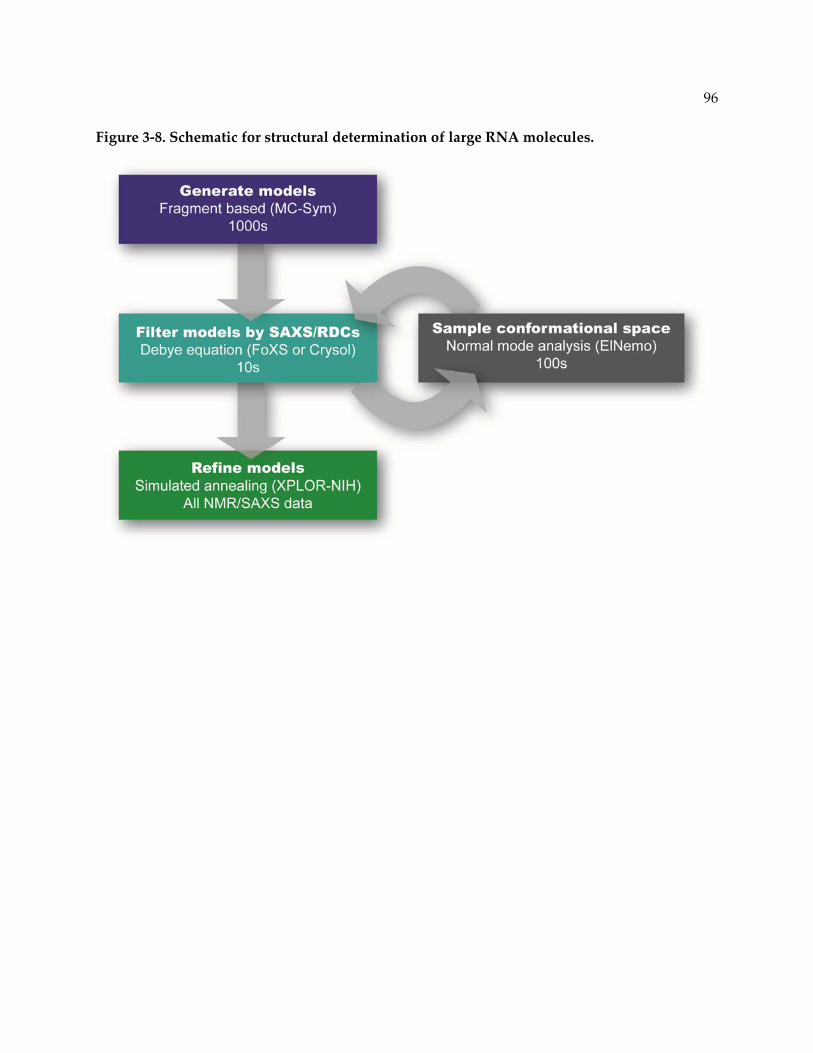
96
Figure 3‐8. Schematic for structural determination of large RNA molecules.

97
Figure 3‐9. Refinement of structural models against SAXS and RDC measurements.
A. The 10 best models of 2500 generated by MC‐Sym were selected based on agreement with
SAXS and RDC measurements. Predicted (solid lines) and experimental (black circles)
scattering profiles of the unrefined models diverge at q > 0.25 Å‐1. B. Experimentally measured
RDC measurements and calculated RDC values for the unrefined models agree with Q factors
of less than 0.35. C. The 10 selected models were further refined against SAXS data, base‐pairing
restraints and RDC measurements by simulated annealing in XPLOR‐NIH, significantly
improving the fit to the SAXS data at > 0.25 Å‐1. D. Refinement improves the RDC Q factor to
less than 0.15 for all models.

98
Table 3‐2. Filtering and refinement statistics of structural models of U2/U6.
Model RDC Q RDC R2 SAXS χ2 RDC Q (refined)
RDC R2 (refined)
SAXS χ2 (refined)
1 0.32 0.79 2.0 0.07 0.99 0.87
2 0.31 0.88 1.8 0.07 0.99 0.85
3 0.24 0.93 1.7 0.07 0.99 0.86
4 0.29 0.67 2.2 0.08 0.99 0.94
5 0.31 0.92 0.8 0.09 0.99 0.93
6 0.26 0.84 2.0 0.08 0.99 0.89
7 0.24 0.77 1.6 0.08 0.99 0.91
8 0.29 0.85 2.0 0.07 0.99 0.86
9 0.31 0.87 1.1 0.12 0.99 0.63
10 0.25 0.88 1.5 0.09 0.99 0.65

99
Figure 3‐10. The U2/U6 complex assumes an extended conformation in solution.
A. The ten lowest energy refined structural models have an overall backbone RMSD of 1.9 Å.
Structural features are color‐coded as in Figure 3‐1. The models agree well with the ab initio
structure of U2/U6 (pale blue). B. Lowest energy refined structural model of U2/U6. C. The U‐
rich loop of the three‐helix junction tucks underneath the base of the U6 ISL, resulting in a
zigzag shape between Helices II and III. D. The phosphates of the U80 metal binding site and
residues U6‐G52 and U2‐A24 are shown as space‐filling. The AGC triad (U6 residues 59‐61)
and residues in the 5’ splice site (U6‐47 to 51) and branchpoint (U2‐33 to 38) recognition
sequences are labeled.

100
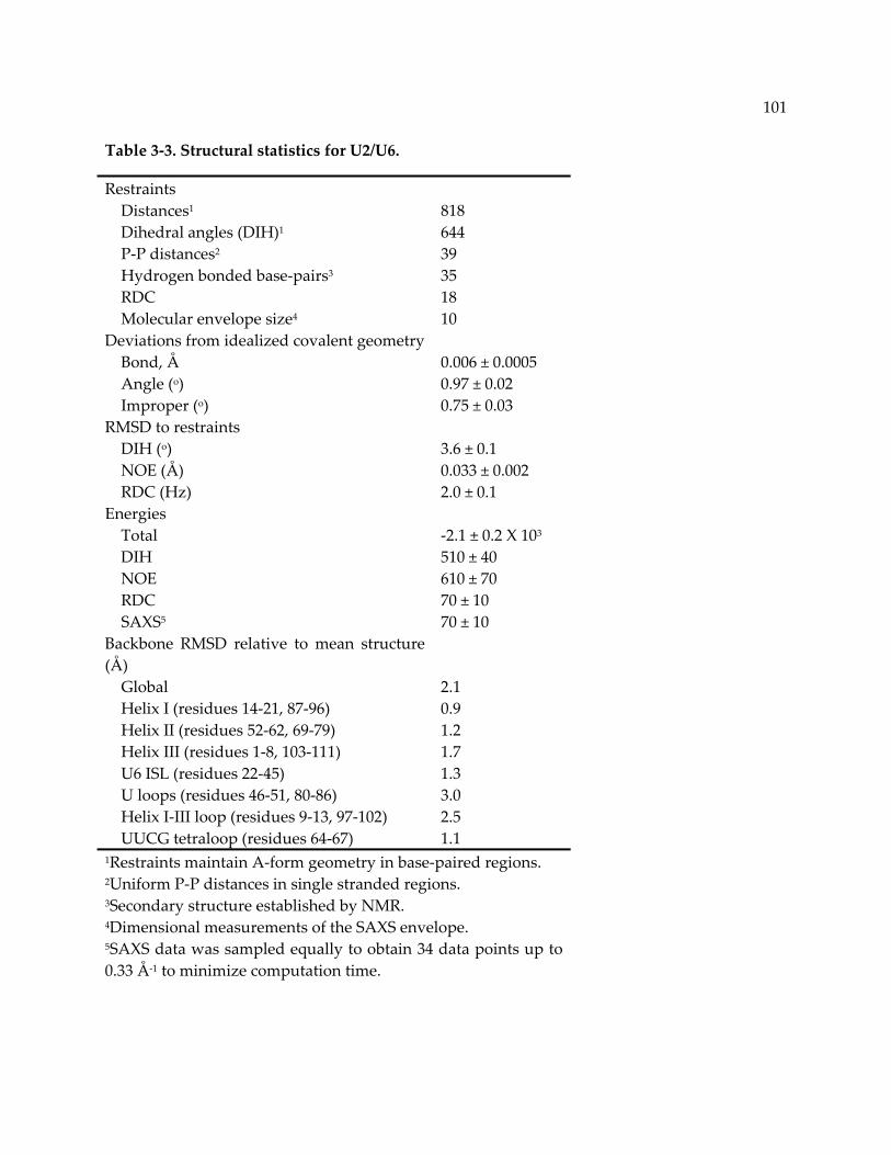
101
Table 3‐3. Structural statistics for U2/U6.
Restraints Distances1 818 Dihedral angles (DIH)1 644 P‐P distances2 39 Hydrogen bonded base‐pairs3 35 RDC 18 Molecular envelope size4 10 Deviations from idealized covalent geometry Bond, Å 0.006 ± 0.0005 Angle (o) 0.97 ± 0.02 Improper (o) 0.75 ± 0.03 RMSD to restraints DIH (o) 3.6 ± 0.1 NOE (Å) 0.033 ± 0.002 RDC (Hz) 2.0 ± 0.1 Energies Total ‐2.1 ± 0.2 X 10³ DIH 510 ± 40 NOE 610 ± 70 RDC 70 ± 10 SAXS5 70 ± 10 Backbone RMSD relative to mean structure (Å)
Global 2.1 Helix I (residues 14‐21, 87‐96) 0.9 Helix II (residues 52‐62, 69‐79) 1.2 Helix III (residues 1‐8, 103‐111) 1.7 U6 ISL (residues 22‐45) 1.3 U loops (residues 46‐51, 80‐86) 3.0 Helix I‐III loop (residues 9‐13, 97‐102) 2.5 UUCG tetraloop (residues 64‐67) 1.1 1Restraints maintain A‐form geometry in base‐paired regions. 2Uniform P‐P distances in single stranded regions. 3Secondary structure established by NMR. 4Dimensional measurements of the SAXS envelope. 5SAXS data was sampled equally to obtain 34 data points up to 0.33 Å‐1 to minimize computation time.

102
3.5 Discussion
Analysis of the structure of U2/U6 by NMR presented unique challenges due to its
relatively large size (36 KDa) and extended shape. Therefore, we utilized a combined approach
that integrates the complementary biophysical techniques of SAXS and NMR along with state of
the art molecular modeling tools (MC‐Sym [162]) to generate structural models. Additionally,
refinement of all‐atom models against both SAXS and RDC measurements resolves
degeneracies inherent in both techniques, as previously demonstrated [140, 229].
3.5.1 Energetically similar U2/U6 structures
Here we report the experimentally determined secondary structure of the U2/U6
complex (Figure 3‐4 and Figure 3‐5A). U2/U6 is predicted to have multiple energetically similar
alternative folds [100]. Previously, we observed an alternate secondary structure involving a
four‐helix junction for truncated versions of the U2/U6 sequence [96]. This secondary structure
is similar to the human U2/U6 conformation, which is typically depicted as a four‐helix junction
[25]. In larger constructs we observe a three‐helix junction, which is consistent with extensive
genetic studies [23, 97, 98]. Previously studied U2/U6 constructs were truncated in either Helix
I, Helix II or both [96], whereas the 111 nt construct studied here contains the full‐length helices.
We hypothesize that destabilization of the flanking helices promotes formation of the
competing U2 Stem I structure observed in the four‐helix junction [96]. Thus, the stability of
Helices I and II is likely an important factor for formation of the three‐helix junction
conformation.
We also observe formation of Helix III for the first time in the S. cerevisiae sequence.
Based on crosslinking results, Helix III has been proposed to form in the human spliceosome

103
[25]. We do not observe the formation of any stable base‐pairs in the loop between Helix I and
Helix III. Because such base‐pairing interactions would preclude pairing with the pre‐mRNA
substrate, maintaining a dynamic or open structure in this region may be important for
function.
3.5.2 Coaxial stacking stabilizes minimal interactions
The three‐helix junction secondary structure of U2/U6 forms the basis for the overall “Y”
shape of the RNA. Three‐way junctions have been found to assume a well‐defined
configuration of helices based on the length of linker sequences within the junction [167]. This
configuration defines the three‐dimensional topology of the RNA and can either facilitate or
prevent long‐range tertiary contacts. In U2/U6, the covalent connection between Helix Ib and
the U6 ISL results in a continuous stack, which manifests as a long axis composed of Helices I
and III and the ISL. Helix I exhibits a linear, coaxially stacked conformation due to extrusion of
a 2 nt bulge between Helix Ia and Ib (see Chapter 4 for more detail). Based on a nearest‐
neighbor rules [230], formation of isolated Helix Ib is not energetically favorable (ΔG37°C ~ 0.1
kcal/mol in 1 M NaCl). Therefore, the stacking interactions we observe in U2/U6 may be
important for stabilizing Helix Ib in the context of the active spliceosome. The coaxial stacking
interaction between Helix Ib and the U6 ISL also determines the relative twist of the helices that
positions the U80 metal binding site on the same face as other essential elements in U6 (Figure
3‐10D).
The conformation of the U2/U6 complex is consistent with the previously determined
structures of the isolated U6 ISL [59, 61] and Helix I (PDB ID 2LK3, Chapter 4). Additionally,
the bulge region of Helix I is known to crosslink to the 5’ splice site recognition sequence (U6‐
G52) in both the S. cerevisiae [216] and human sequences [217]. U6‐G52 has also been observed

104
to have a genetic interaction with the Helix I bulge in S. cerevisiae [218]. This observation led to
the proposal that U6‐G52 forms a mismatch pair with U2‐A25 [218]. We find that backbone
phosphates of these residues are approximately 16 Å apart in the structural models of U2/U6
(Figure 3‐10D), although the bases are not oriented toward one another in our model.
However, modeling exercises suggest that flipping these bases out of their respective helices
would allow them to come within van der Waals contact distance of each other (data not
shown).
3.5.3 An RNA scaffold for extensive interactions within the spliceosome
U2/U6 has been frequently compared to the group II intron based on mechanistic and
structural similarities [205]; however, formation of the group II intron active site is dependent
on an extensive network of stabilizing RNA tertiary interactions including kissing loops and
tetraloop‐receptor interactions [212]. The vast size difference between the conserved portions of
the U2/U6 complex and even the smallest group II introns implies that other components are
responsible for these stabilizing interactions in the spliceosome. Protein splicing factors likely
play a large role in buttressing RNA interactions in the active site of the spliceosome. While we
observe stacking between Helix Ib and the U6 ISL similar to the structure of domain V of the
group II intron, we do not observe formation of analogous base‐triple interactions that
constitute the group II intron active site. Nevertheless, it is interesting that highly conserved
motifs in U6 snRNA, including the AGC triad, the 5’ splice site recognition sequence and the
U80 metal binding site align to one face of the U2/U6 complex. In the mammalian spliceosome,
the nucleotide equivalent to U80 approaches the 5’ splice site at least some of the time [215], as
indicated by hydroxyl radical experiments which can diffuse over distances of up to 24 Å [231].
Additionally, in a construct containing sequences from the yeast U2/U6 complex, smFRET

105
studies demonstrate that the U6 ISL approaches Helix III at concentrations of MgCl2 of 10 mM
or greater [219]. However, we observe that U80 is distal to the 5’ splice site recognition
sequence, and detect no large‐scale conformational change by SAXS in the presence of 10 mM
MgCl2. The discrepancy between these studies may be related to differences in the RNA
sequences investigated. In the spliceosome, the U6 ISL and Helix III regions may come into
closer proximity upon activation, which occurs in the presence of the pre‐mRNA substrate and
also a multitude of protein splicing factors [3]. This is consistent with the observation that the
mammalian sequence of U2/U6 has a very low level of catalytic activity in the absence of
protein [104, 105, 207‐209].
The hypothesis that protein and substrate are required for a catalytically active
conformation is also consistent with the kinetic proofreading model of spliceosome activation
[232]. During this process a number of DExD/H box helicases are necessary for rearrangement
of interactions between the substrate and mRNAs. A large number of regulatory steps must
occur before spliceosome activation is possible, during which pauses allow for non‐ideal pre‐
mRNA substrates to be discarded [232]. A ground state “inactive” conformation of U2/U6
during the final stages of activation may allow for such a pause before the first step of splicing
and then again before the second step as the 3’ splice site is positioned [233]. The extended
conformation we observe may represent such a ground state structure.
Alternatively, the face containing the essential elements of U6 could represent a protein
binding scaffold. The U5 snRNP protein Prp8 has been observed to crosslink to both the pre‐
mRNA substrate and the U6 snRNA at the 5’ splice site [107, 234]. The 5’ splice site consensus
sequence and the 5’ splice site recognition sequence of U6 form an unstable complex [209]. A
protein factor such as Prp8 may assist stabilization of the pre‐mRNA/U6 complex during the

106
first step of splicing. In this case, the large cleft between the U6 ISL and the pre‐mRNA binding
site could accommodate both the substrate and a protein factor. The minimal U2/U6 complex
presented here constitutes only 1‐2% of the molecular weight of the spliceosomal C complex.
However, due to the extended shape of U2/U6, the length of the complex is larger than may
have otherwise been expected. Strikingly, the length of U2/U6 (117 Å) is approximately 40% the
width of the salt stable core of the yeast C complex (Figure 3‐11) [129]. This remarkable
similarity in scale may implicate U2/U6 as a platform for protein and RNA interactions within
the spliceosome.
Here we have investigated the ground state structure of the U2/U6 complex. We
developed a method for analysis of this relatively large molecule in solution using sparse NMR
data and SAXS. Determination of the free U2/U6 structure provides the relative configuration
of essential RNA components in the absence of proteins and may provide insight into the
structural and functional role of other essential splicing factors necessary for formation of the
spliceosomal active site.

107
Figure 3‐11. The U2/U6 complex within the active spliceosome.
The U2/U6 snRNA complex (blue) spans ~40% the width of the salt stable core of the C complex
(gray mesh) [129] despite constituting only 1‐2% of the total mass of the activated spliceosome.

108
3.5.4 Acknowledgements
We thank Lawrence Clos II, Marco Tonelli and the National Magnetic Resonance Facility
at Madison (NMRFAM) staff as well as Soenke Seifert and the Advanced Photon Source (APS)
staff for technical support. We also thank David Brow, Alex Grishaev and all the members of
the Butcher lab for helpful discussions. This study made use of the National Magnetic
Resonance Facility at Madison, which is supported by NIH grants P41RR02301 (BRTP/ NCRR)
and P41GM66326 (NIGMS). Additional equipment was purchased with funds from the
University of Wisconsin, the NIH (RR02781, RR08438), the NSF (DMB‐8415048, OIA‐9977486,
BIR‐9214394), and the USDA. Use of the Advanced Photon Source, an Office of Science User
Facility operated for the U.S. Department of Energy (DOE) Office of Science by Argonne
National Laboratory, was supported by the U.S. DOE under Contract No. DE‐AC02‐
06CH11357. J.E.B. was supported by NIH Predoctoral training grant T32 GM07215‐34. This
work was supported by NIH grant GM065166 to S.E.B.
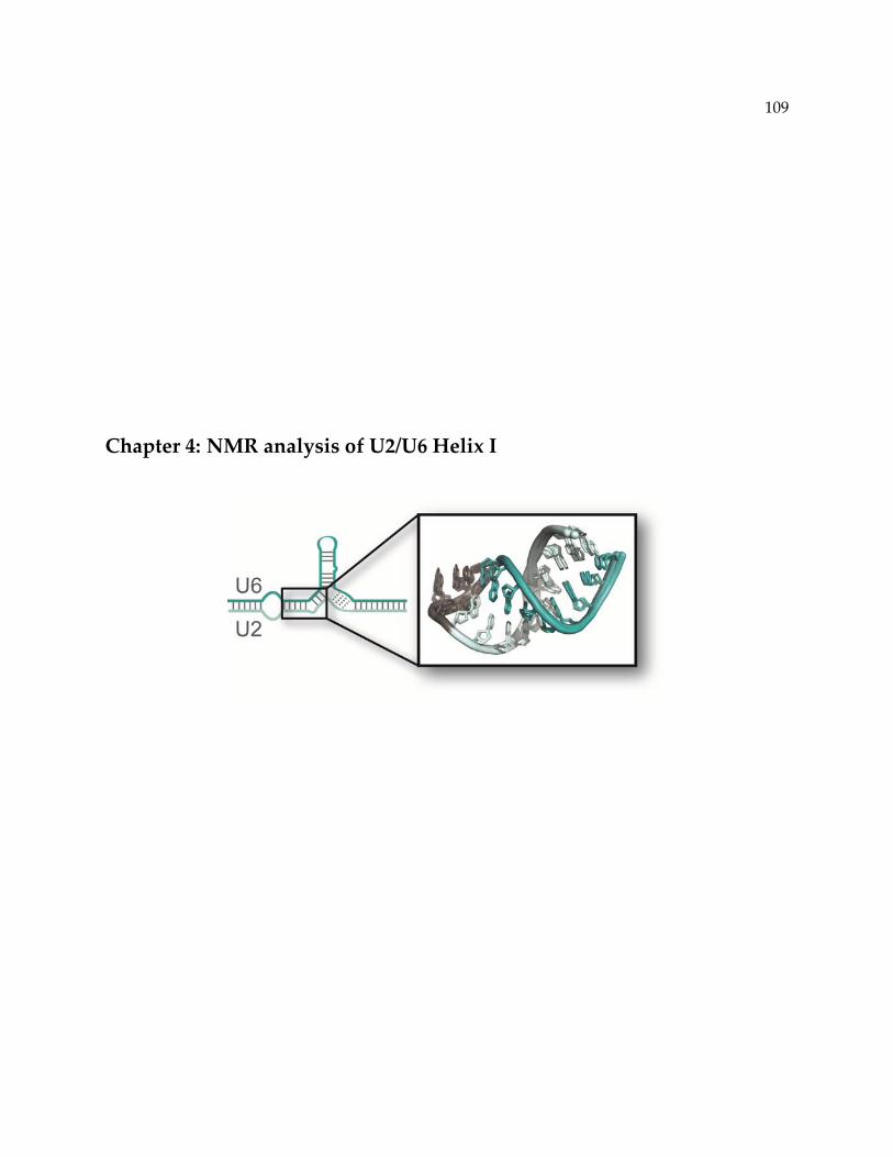
109
Chapter 4: NMR analysis of U2/U6 Helix I

110
4.1 Introduction
U2 and U6 snRNA molecules form an essential conserved interaction in all eukaryotes
[23, 25, 68]. Central to this interaction is Helix I, which is composed of two short helices, Ia and
Ib, that are separated by a two nucleotide bulge. While Helix Ia is essential in yeast and
humans, the existence of Helix Ib is somewhat controversial due to the presence of competing
intramolecular structures in both U2 and U6. Several roles have been proposed for Helix I in
splicing, including 5’ and 3’ splice site and branchpoint selection, metal ion coordination and
catalysis.
The sequence and base‐pairing potential of Helix I is highly conserved across phylogeny
(Table 4‐1). Helix Ia contains five Watson‐Crick pairs in S. cerevisiae, but only three Watson‐
Crick pairs and one G‐U wobble pair in most other organisms (Table 4‐1). Disruption of the
base‐pairs in Helix Ia closest to the Helix I bulge (Table 4‐1, blue) is lethal in yeast [23] and
required for efficient splicing of a reporter construct in by human cell extract utilizing mutated
U2 and U6 RNAs [25]. Furthermore, restoration of pairing rescues this phenotype in both
systems. The size of the 2 nt bulge that separates Helix Ia and Ib is conserved in nearly all
organisms (Table 4‐1). In contrast, the identity of the nucleotides is highly conserved in
metazoans (5’‐AA‐3’) but less so in single celled eukaryotes, varying from UA in S. cerevisiae to
AU in T. gondii to AA in C. neoformans (Table 4‐1).

111
Table 4‐1. Conservation of U6 and U2 sequences contributing to Helix I.
Species Helix I: U6 Helix I: U2
Cryptosporidium muris 5’-AGAUU--AGC-3’
3’-ACUAGUAUCG-5’
Toxoplasma gondii 5’-AGAUU--AGC-3’
3’-ACUAGUAUCG-5’
Saccharomyces cerevisiae 5’-UGAUC--AGC-3’
3’-ACUAGAUUCG-5’
Candida albicans 5’-AAAUU--AGC-3’
3’-CCUAGAUUCG-5’
Cryptococcus neoformans 5’-AGAUU--AGC-3’
3’-ACUAGAAUCG-5’
Caenorhabditis elegans 5’-AGAUU--AGC-3’
3’-ACUAGAAUCG-5’
Arabidopsis thaliana 5’-AGAUU--AGC-3’
3’-ACUAGAAUCG-5’
Drosophila melanogaster 5’-AGAUU--AGC-3’
3’-ACUAGAAUCG-5’
Mus musculus 5’-AGAUU--AGC-3’
3’-ACUAGAAUCG-5’
Homo sapiens 5’-AGAUU--AGC-3’
3’-ACUAGAAUCG-5’

112
The functional requirement for Helix Ib is less clear and has mainly been studied in
yeast [25]. Mutations in the invariant AGC triad in U6 result in either lethality or temperature
sensitivity [23, 63] and the compensatory U2 substitutions restore growth. However,
introduction of the same U2 mutations in a wild‐type U6 background has no effect on growth,
except in the case of U2‐G21C. This result suggests that the identity of the residues in this region
is more important than maintenance of base‐pairing. Other substitutions at position U2‐U23
(Figure 3‐1) do result in a quantitative splicing defect, as measured by in vitro splicing assays,
despite not altering growth [23]. Additionally, yeast become more sensitive to branchpoint or 3’
splice site substitutions when U2 residues 21‐23 are mutated, and this phenotype is rescued by
compensatory mutations in U6 [97, 98].
Helix Ib is likely replaced in the human U2/U6 structure by a competing intramolecular
U2 structure, U2 stem I (Figure 1‐7) [25]. Base‐pairing potential in U2 Stem I is conserved across
phylogeny [99]. Furthermore mutations in U2 residues involved in both U2 Stem I and Helix Ib
are suppressed by restoration of the corresponding base‐pairs in U2 Stem I, but not Helix Ib in
human cells [25]. U2 stem I constitutes one part of the so‐called four‐helix junction
conformation of U2/U6, which has been detected by NMR studies [96]. Energy minimization
[100] and single molecule FRET analysis of the yeast U2/U6 sequence [219] suggests that these
two conformations are close in free energy, indicating that U2/U6 may switch dynamically
between them. However, the functional conformation of yeast U2/U6 in vivo remains
controversial.
Helix I has been implicated in both regulatory and catalytic roles during splicing
including: 5’ splice site, branchpoint and 3’ splice site selection and Mg2+ coordination during
catalysis. Helix I is adjacent to the region of U6 that recognizes the 5’ splice site [201, 235] and

113
the region of U2 that recognizes the branchpoint [12], and is therefore involved in substrate
positioning before the first step of splicing [23]. Some substitutions of U2 residues within Helix I
suppress splicing defects caused by mutation of U6‐G52 [218], which directly interacts with the
5’ splice site. This genetic interaction suggests that the Helix I bulge may interact with the 5’
splice site during catalysis, which has been further confirmed by crosslinking [216] and
structural studies [95]. In contrast, any substitution of U2‐U23 is synthetic lethal with a
substitution in the 5’ splice site recognition sequence [236]. U2‐U23C results in hyper‐accurate 5’
splice site selection and restoration of the corresponding base‐pair in Helix Ib restores 5’ splice
site selection [236]. Therefore the Helix I structure, rather than the identity of the isolated
residues within, may be necessary for the first step of splicing [236].
Branchpoint and 3’ splice site choice may also be influenced by Helix I. Mutation of U6‐
U57 allows splicing of an mRNA containing a branchpoint substitution (G, C or U) [63].
Mutation of U6‐U57 increases the use of a cryptic 3’ splice site in a pre‐mRNA containing a
shortened branchpoint‐3’ splice site spacing and a 3’ splice site mutation [237], leading to the
hypothesis that Helix Ia may play a role in selecting and positioning the 3’ splice site. This role
is further supported by the observation that Helix Ia has strong genetic interactions with Prp16,
the DExD/H box helicase responsible for rearrangement between the two steps of splicing [114].
Disruption of two base‐pairs in Helix Ia by substitutions in the U6 strand suppresses a cold
sensitive PRP16 allele [114]. However, this effect appears to be sequence specific as the
compensatory mutations in U2 do not inhibit growth [114].
Finally, U2/U6 Helix I is thought to play a direct role in splicing catalysis. The invariant
AGC triad has been implicated in splicing catalysis based on its homology to the catalytic core
of the group II self‐splicing intron (see Section 1.7.2) [205, 206]. The (A/C)GC triad in the group

114
II intron forms a scaffold for coordination of two Mg2+ ions [103, 212] that are thought to
stabilize SN2 transition states during each step of splicing [103]. Residual in vitro splicing
activity of the human U2/U6 sequence is dependent on Mg2+ coordination at U6‐A59 [104, 105].
While metal ion coordination by the U6 ISL is well characterized (see Section 1.2.2) [59, 62],
direct evidence for metal binding by U2/U6 Helix I in vivo remains elusive.
To gain a better understanding of the role of this essential spliceosomal component, we
solved the solution structure of the yeast sequence of Helix I and performed preliminary
analyses of its metal binding properties. The structure reveals a linear conformation of Helix Ia
and Ib in which the bulge is extruded into the minor groove. Mg2+ causes chemical shift
perturbation in the imino 1H resonances of residues immediately adjacent to the Helix I bulge,
but not aromatic 1H resonances. This result suggests a potential conformational rearrangement
near the bulge in the presence of Mg2+ coordination site observed in the group II intron and the
human U2/U6 sequence.

115
4.2 Materials and Methods
4.2.1 NMR sample preparation
The 24 nt Helix I RNA contains the Helix Ia and Helix Ib sequences from S. cerevisiae
connected by a GAAA or GUGA tetraloop and stabilized by an additional GC pair on Helix Ib
as follows: 5’‐GGC UUA GAU CAG AAA UGA UCA GCC‐3’ or 5’‐GGC UUA GAU CAG UGA
UGA UCA GCC‐3’. RNA was transcribed in vitro from DNA oligonucleotides (Integrated DNA
Technologies), containing a 21 nt promoter and the template sequence for the RNA, using
purified His6‐tagged T7 RNA polymerase. 13C‐15N labeled samples were prepared using 13C‐15N
labeled nucleotides (Cambridge Isotope Laboratories).
RNA samples were purified using denaturing 12% PAGE with 8 M urea. Impurities
were removed by DEAE anion‐exchange (Biorad) using a low salt buffer (20 mM Tris‐HCl, pH
7.6, 200 mM sodium chloride) to wash and a high salt buffer (20 mM Tris‐HCl, pH 7.6, 1.5 M
sodium chloride) to elute the RNA. Samples were then ethanol precipitated and resuspended in
miliQ deionized H2O, then desalted by size exclusion and lyophilized until dry. The resulting
samples were resuspended in miliQ deionized H2O and the pH was adjusted to 7.0 using the
RNA as a buffer. Samples were also lyophilized and resuspended in 99.9% D2O for detection of
ribose 1H resonances.
Imino 1H resonances were assigned using 1H‐1H 2D NOESY with a mixing time of 150
ms and 1H‐15N 2D HMQC and HNN‐COSY experiments in 90% H2O, 10% D2O at 10°C (BMRB
entry 17972). Aromatic and ribose 1H resonances were determined using 1H‐1H 2D NOESY,
HCCH 3D total correlation spectroscopy (TOCSY) and 1H‐13C 2D HSQC in 99.9% D2O at 25°C
(BMRB entry 17972). Chemical shift changes as a function of Mg2+ concentration were

determin
RNA (GU
R
phospha
phage co
1H RDC
1H reson
4.2.2 Stru
T
3) [95]. T
NOE me
(exchang
quantitat
(2.0−4.5 Å
standard
conforma
structure
50 structu
ned by titrati
UGA constru
Residual dip
te, pH 7.0 w
oncentration
measuremen
ances by 1H‐
ucture determ
The RNA sam
The structur
asurements
geable proto
tively binne
Å) and weak
d values ( 1
ations for
es were calcu
ures were re
ing small vo
uct) and acq
polar coupl
with and w
was confirm
nts were obt
‐15N HMQC
mination of He
mple was pr
re of Helix I
were obtain
ns) and 350
d to three c
k (3.0−5.5Å)
5°). C2’‐end
residues w
ulated using
efined using
olumes of 50
quiring 1H 1D
ling measur
without 20 m
med by meas
tained using
. RDC measu
elix I
repared in th
I (GAAA) w
ned from 1H‐
0 ms (non‐ex
categories ba
. Torsion an
do sugar pu
with weak H
g CNS 1.1 [2
XPLOR‐NIH
00 mM or 1 M
D or 1H‐1H 2
rements we
mg/ml Pf1 f
suring 2H sp
g a 1H‐13C co
urements w
he same man
was solved b
‐1H 2D NOE
xchangeable
ased on pea
ngle restraint
ucker was de
H1’‐H2’ cou
238] as descr
H [239] usin
M MgCl2 (1‐
2D TOCSY sp
ere conduc
filamentous
plitting at 75
onstant time
were in the ra
nner as the
by NMR in l
ESY spectra w
e protons). N
ak intensity:
ts for A‐form
etected by 1H
uplings we
ribed [102].
ng 42 RDC re
‐2% sample
pectra at eac
cted in 10
bacterioph
50 MHz. Aro
e J‐coupled H
ange of ‐18.8
111 nt U2/U
low ionic str
with a mixin
NOE cross‐p
strong (1.8−
m helical reg
H‐1H TOCSY
ere left unr
The 10 lowe
estraints.
volume) int
ch concentra
mM potas
age (ASLA)
omatic and r
HSQC and i
to 20.6 Hz.
U6 RNA (Ch
rength at pH
ng time of 15
peaks were s
−3.0 Å), me
gions were s
Y. Sugar pu
restricted. I
est‐energy o
116
to the
ation.
ssium
). Pf1
ribose
imino
hapter
H 7.0.
50 ms
semi‐
dium
set to
ucker
Initial
out of
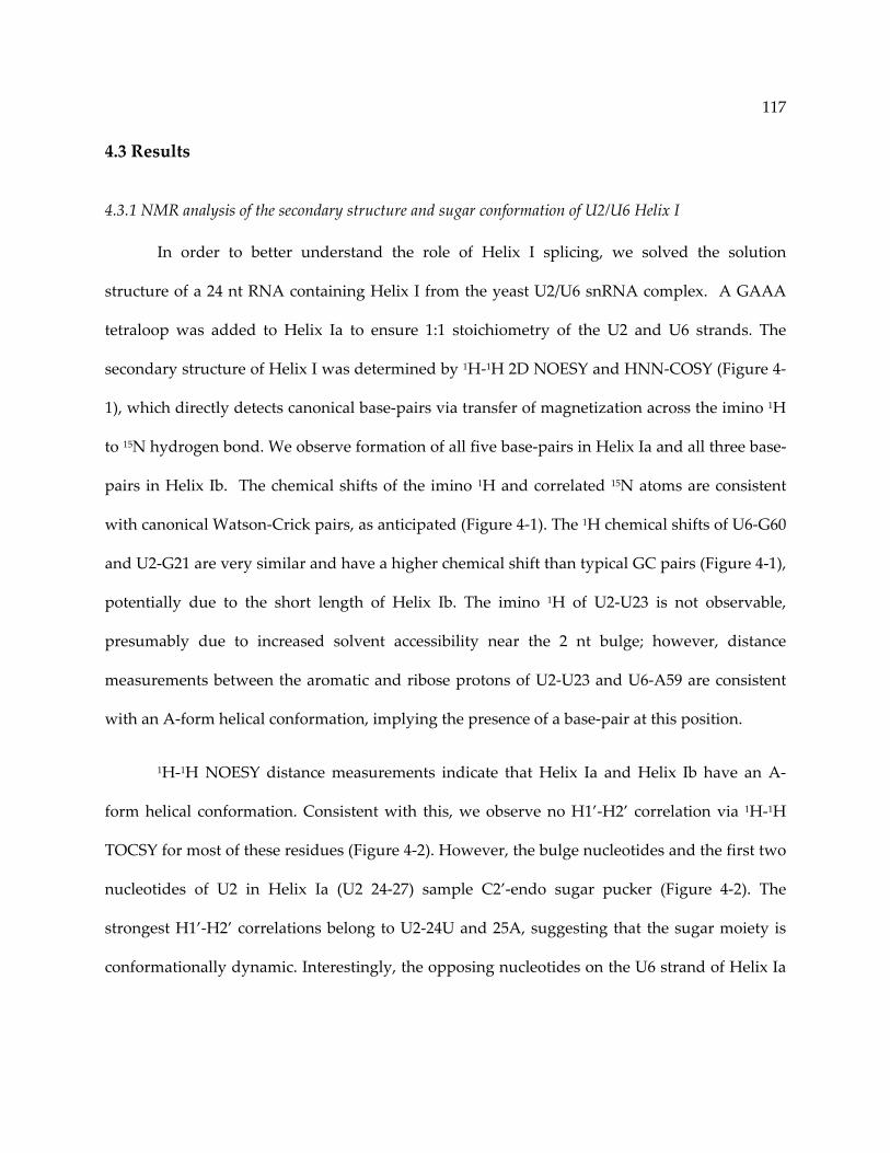
117
4.3 Results
4.3.1 NMR analysis of the secondary structure and sugar conformation of U2/U6 Helix I
In order to better understand the role of Helix I splicing, we solved the solution
structure of a 24 nt RNA containing Helix I from the yeast U2/U6 snRNA complex. A GAAA
tetraloop was added to Helix Ia to ensure 1:1 stoichiometry of the U2 and U6 strands. The
secondary structure of Helix I was determined by 1H‐1H 2D NOESY and HNN‐COSY (Figure 4‐
1), which directly detects canonical base‐pairs via transfer of magnetization across the imino 1H
to 15N hydrogen bond. We observe formation of all five base‐pairs in Helix Ia and all three base‐
pairs in Helix Ib. The chemical shifts of the imino 1H and correlated 15N atoms are consistent
with canonical Watson‐Crick pairs, as anticipated (Figure 4‐1). The 1H chemical shifts of U6‐G60
and U2‐G21 are very similar and have a higher chemical shift than typical GC pairs (Figure 4‐1),
potentially due to the short length of Helix Ib. The imino 1H of U2‐U23 is not observable,
presumably due to increased solvent accessibility near the 2 nt bulge; however, distance
measurements between the aromatic and ribose protons of U2‐U23 and U6‐A59 are consistent
with an A‐form helical conformation, implying the presence of a base‐pair at this position.
1H‐1H NOESY distance measurements indicate that Helix Ia and Helix Ib have an A‐
form helical conformation. Consistent with this, we observe no H1’‐H2’ correlation via 1H‐1H
TOCSY for most of these residues (Figure 4‐2). However, the bulge nucleotides and the first two
nucleotides of U2 in Helix Ia (U2 24‐27) sample C2’‐endo sugar pucker (Figure 4‐2). The
strongest H1’‐H2’ correlations belong to U2‐24U and 25A, suggesting that the sugar moiety is
conformationally dynamic. Interestingly, the opposing nucleotides on the U6 strand of Helix Ia

118
still maintain C3’‐endo conformation, but U6‐A59 samples a C2’‐endo conformation (Figure
4‐2).

119
Figure 4‐1. Base‐pairing in Helix I as determined by HNN‐COSY.
Dark blue cross‐peaks indicate direct correlations and light blue cross‐peaks indicate cross
hydrogen bond correlations. Typical chemical shift ranges for different atom types are indicated
with black bars on the right hand side of the spectrum.

120
Figure 4‐2. The bulge nucleotides sample C3’‐endo sugar pucker.
1H‐1H 2D TOCSY spectrum of Helix I RNA. Intense H1’ to H2’ cross‐peaks indicate the sugar
pucker is conformationally averaged between H2’ endo and H3’ endo.

121
4.3.2 Solution structure of Helix I
The structure of the 24 nt Helix I construct was determined by NMR using 243 NOE
distance restraints and 42 residual dipolar coupling (RDC) restraints by simulated annealing in
XPLOR‐NIH [239] (Figure 4‐3A). Helix I has a linear conformation in which Helix Ia and Ib are
continuous (Figure 4‐3A) and exclude the two nucleotide bulge into the minor groove of the
Helix Ib (Figure 4‐3B). This conformation places the bulge residues in close proximity to the
AGC triad. The linear structure of Helix I is consistent with its conformation in the context of
the 111 nt U2/U6 RNA and the two have an RMSD of 2.1 Å (Figure 4‐3C, Chapter 3) [95].
While the sequence of the Helix I bulge varies between yeast and mammalian U2
snRNA molecules, the length of the bulge is conserved. These nucleotides are predicted to
remain unpaired even in the absence of Helix Ib formation [25, 96]. U2‐U24 has a genetic
interaction with and crosslinks to U6‐G52 [216‐218] in the 5’ splice site recognition region of U6.
Extrusion of the first bulge nucleotide from the helix may help facilitate this interaction by
forming a functionally important long‐range contact.
Additionally, we find that U2‐A25 is planar with the last pair in Helix Ib (U6‐A59 to U2‐
U23) (Figure 4‐3B). We do not directly detect hydrogen bonding between U2‐A25 and U6‐A59
by NMR and have therefore included no restraints for such an interaction during simulated
annealing. Despite this, we observe that the distance between the amino H6 of U2‐A25 and the
N3 of U6‐A59 is only ~1 Å longer than the appropriate distance for a hydrogen bond (Figure
4‐3B), providing the potential for formation of a base‐triple at this position.
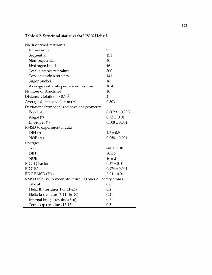
122
Table 4‐2. Structural statistics for U2/U6 Helix I.
NMR derived restraints Intraresidue 93 Sequential 131 Non‐sequential 30 Hydrogen bonds 46 Total distance restraints 300 Torsion angle restraints 141 Sugar pucker 18 Average restraints per refined residue 18.4 Number of structures 10 Distance violations > 0.5 Å 2 Average distance violation (Å) 0.503 Deviations from idealized covalent geometry Bond, Å 0.0023 ± 0.0006 Angle (o) 0.72 ± 0.01 Improper (o) 0.308 ± 0.004 RMSD to experimental data DIH (o) 1.6 ± 0.9 NOE (Å) 0.058 ± 0.004 Energies Total ‐4100 ± 30 DIH 80 ± 5 NOE 46 ± 2 RDC Q Factor 0.27 ± 0.01 RDC R2 0.974 ± 0.001 RDC RMSD (Hz) 2.04 ± 0.04 RMSD relative to mean structure (Å) over all heavy atoms Global 0.6 Helix Ib (residues 1‐4, 21‐24) 0.2 Helix Ia (residues 7‐11, 16‐20) 0.2 Internal bulge (residues 5‐6) 0.7 Tetraloop (residues 12‐15) 0.3

123
Figure 4‐3. Linear conformation of U2/U6 Helix I.
A. Secondary and solution structure (PDB ID 2LK3) of the 24 nt Helix I RNA as determined by
NMR. Base‐pairing as determined by NMR is indicated with black lines. Base‐pairs in which the
imino 1H is not detectable but other distance measurements are consistent with base‐pair
formation are shown with light gray lines. Non‐native residues are shown in gray, residues in
Helix Ia or Ib are shown in light green and the bulge nucleotides are shown in dark green. B.
The planar orientation of U2‐A25 with the last base‐pair in Helix Ib (U6‐A59 to U2‐U23).
Hydrogen bonds are indicated with black dashed lines. The potential hydrogen bond between
U2‐A25 and U6‐A59 is indicated with a gray dashed line. C. Agreement of the isolated Helix I
structure (green) with the overall conformation of U2/U6 (gray or black in Helix I region) as
shown in the 111 nt RNA described in Chapter 3 (PDB ID 2LKR). The respective lengths of the
U6 ISL and Helix I are labeled.
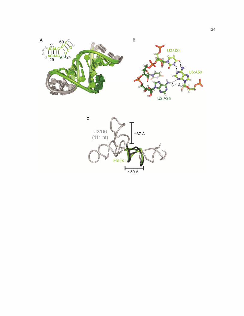
124

125
4.3.3 Metal binding properties of Helix I
U6 coordinates Mg2+ at the U6 ISL [62] and potentially the AGC triad [104]. Both of these
sites are thought to be important for splicing activity [62, 105]. The U6 ISL is able to coordinate
Mg2+ independently of the rest of the U2/U6 structure [59]. The AGC triad coordinates Mg2+ in
the context of the human U2/U6 complex in vitro [104], but it remains unclear whether Helix I is
capable of supporting metal binding in isolation from the rest of the complex. While the ISL and
Helix I locations are distal from each other in the ground state U2/U6 structure [95] (Chapter 3),
they may transiently sample a more proximal conformation [215, 219] thereby cooperatively
contributing to metal ion coordination.
To test the Mg2+ binding properties of Helix I, we titrated MgCl2 into the 24 nt Helix I
RNA and examined the perturbation of imino 1H chemical shift by 1H 1D NMR (Figure 4‐4A).
This method is somewhat limited as the only detectable protons are those participating in
Watson‐Crick pairs, excluding the bulge nucleotides. The largest perturbations in chemical shift
are observed for U2‐26G H1 and a resonance that likely belongs to U2‐23U H3 but cannot be
verified by this method due to chemical shift overlap. These protons participate in the two base‐
pairs that are adjacent to the Helix I bulge, suggesting that the bulge region interacts with Mg2+,
or undergoes a conformational change in the presence of Mg2+.
To further confirm this result, the chemical shift perturbation of pyrimidine H5 and H6
resonances was measured as a function of MgCl2 concentration (Figure 4‐4B). Interestingly, the
chemical environment of the H5 and H6 positions of the bulge nucleotides appears to be
unaffected by the presence of Mg2+ (Figure 4‐4B and C). This finding contradicts the chemical
shift perturbation of imino 1H resonances adjacent to the bulge and may indicate that Mg2+
causes a slight shift in the conformation of the bulge. No significant attenuation of signal or

126
additional peaks are observed for any of the 1H resonances around Helix I, suggesting that any
induced changes in conformation are stable.
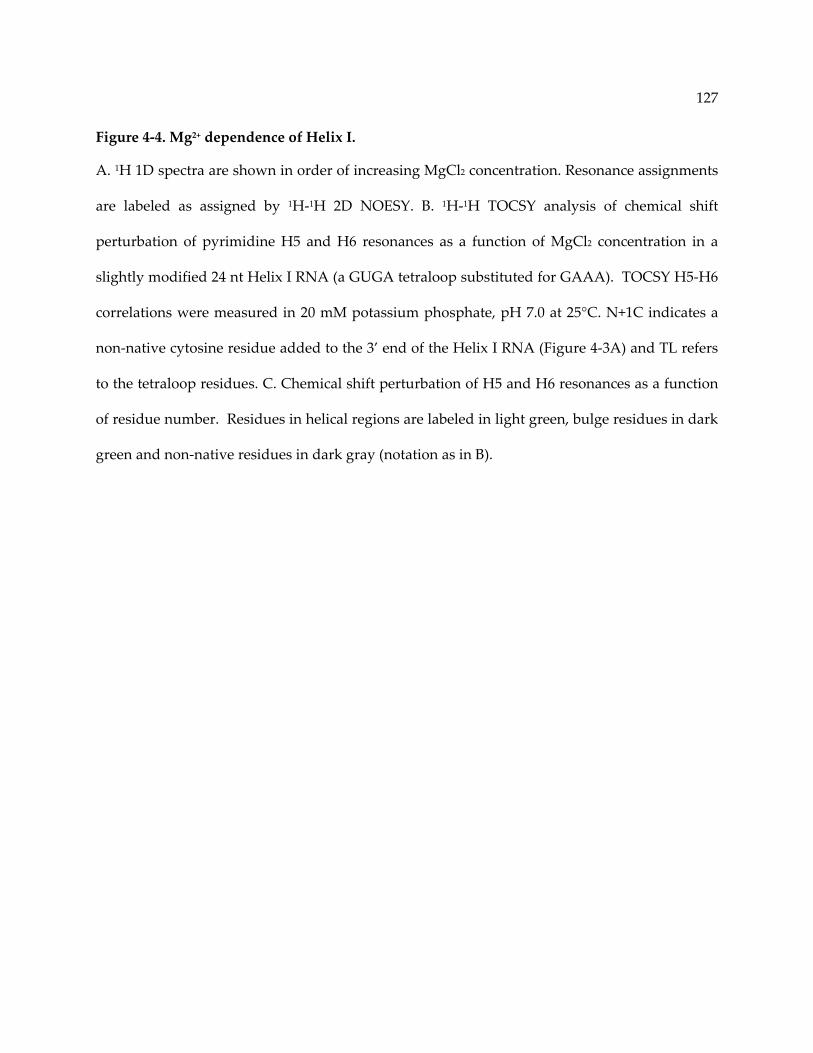
127
Figure 4‐4. Mg2+ dependence of Helix I.
A. 1H 1D spectra are shown in order of increasing MgCl2 concentration. Resonance assignments
are labeled as assigned by 1H‐1H 2D NOESY. B. 1H‐1H TOCSY analysis of chemical shift
perturbation of pyrimidine H5 and H6 resonances as a function of MgCl2 concentration in a
slightly modified 24 nt Helix I RNA (a GUGA tetraloop substituted for GAAA). TOCSY H5‐H6
correlations were measured in 20 mM potassium phosphate, pH 7.0 at 25°C. N+1C indicates a
non‐native cytosine residue added to the 3’ end of the Helix I RNA (Figure 4‐3A) and TL refers
to the tetraloop residues. C. Chemical shift perturbation of H5 and H6 resonances as a function
of residue number. Residues in helical regions are labeled in light green, bulge residues in dark
green and non‐native residues in dark gray (notation as in B).
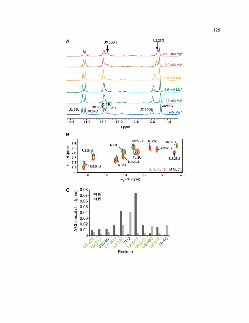
128

129
4.4 Discussion
U2/U6 Helix I contains some of the most highly conserved RNA sequences in the
spliceosome and is likely to be at the heart of splice site selection and catalysis. Helix Ia and Ib
form a continuous stack, resulting in a roughly linear structure. This stacking interaction may
help stabilize Helix Ib, which otherwise contains only the minimum number of base‐pairs to be
thermodynamically advantageous [230]. Helix I is further stabilized by coaxial stacking with the
U6 ISL (Chapter 3) [95]. The linearity of Helix I also results in a very compact structure,
potentially reducing the distance between essential sequences in U2/U6. Helix I is only ~30 Å in
length, while the stem portion of the U6 ISL, which contains the same number of base‐pairs and
only one additional loop nucleotide, is ~37 Å long (Figure 4‐3C).
The linear conformation of Helix I is achieved through extrusion of the 2 nt bulge
between Helix Ia and Ib on the U2 strand. This presence of this bulge is highly conserved across
all eukaryotes and the identity of the bulge nucleotides appears to be functionally important in
yeast [218] and humans [217]. We observe that the bulge nucleotides are tucked into the minor
groove of Helix Ib, allowing the terminal base‐pairs of Helix Ia and Ib to stack. U2‐A25 is
effectively planar with the U6‐A59/U2‐U23 base‐pair and has the potential to hydrogen‐bond
with U6‐A59. However, we observe no evidence for this hydrogen bond by NMR, indicating
that it is transient if present.
The conformation observed here is somewhat reminiscent of Domain V of the group II
intron. The (A/C)GC triad forms a triple helix with the bulge of Domain V and a distal sequence
(junction 2/3) that supports coordination of two Mg2+ ions important for structure and catalysis
[212]. The A of the AGC triad binds Mg2+ in vitro [104] and the AGC triad as a whole has been

130
implicated as part of the spliceosomal active site [24]. These observations are consistent with
our finding that Mg2+ has some impact on the Helix I bulge. Further studies will be necessary to
confirm these metal binding properties and investigate the effect of Mg2+ coordination on the
structure of Helix I. Together with the structure of the entire U2/U6 complex, this study
provides additional details about the spliceosomal active site and the role of essential elements
of U6 in catalysis.
4.4.1 Acknowledgements
We thank Dr. Dipali Sashital for assistance with data collection and the National
Magnetic Resonance Facility at Madison (NMRFAM) staff for technical support. This study
made use of the National Magnetic Resonance Facility at Madison, which is supported by NIH
grants P41RR02301 (BRTP/ NCRR) and P41GM66326 (NIGMS). Additional equipment was
purchased with funds from the University of Wisconsin, the NIH (RR02781, RR08438), the NSF
(DMB‐8415048, OIA‐9977486, BIR‐9214394), and the USDA. J.E.B. was supported by NIH
Predoctoral training grant T32 GM07215‐34. This work was supported by NIH grant GM065166
to S.E.B. and D.A.B.

131
Chapter 5: A novel U2/U6 snRNP enables spliceosome assembly without
stable U4/U6 association
The material presented in this chapter is the result of research performed by the author with
contributions from Prof. David A. Brow and Prof. Samuel E. Butcher.

132
5.1 Abstract
Highlights
• Point mutations induce and stabilize a structural “switch” in the U2/U6 complex.
• Stabilization of a three‐helix junction in U2/U6 can rescue disruption of U4/U6.
• The viable triple mutant accumulates U2/U6 snRNP at the expense of U4‐U6‐U5 snRNP.
• Our results imply an alternative pathway for U6 RNA recycling in the splicing cycle.
Summary
Splicing requires association of pre‐mRNA and five snRNA‐protein complexes (snRNPs)
into a spliceosome. U6 snRNA enters the spliceosome paired to U4 snRNA, but is transferred to
U2 snRNA during spliceosome activation. Here we investigate the RNA conformational
changes that accompany U2/U6 and U4/U6 pairing. Two distal point mutations in U6 induce
large changes in U2/U6 pairing and, in combination, stabilize the wild‐type U2/U6 structure.
Furthermore, a strain containing these two U6 substitutions grows normally. The U6 mutations
also rescue the cold‐sensitive growth caused by a mutation in U4 that destabilizes U4/U6
pairing. The triple mutant strain exhibits no U4/U6 snRNP, diminished U4‐U6‐U5 tri‐snRNP
and greatly increased amounts of a U2/U6 snRNP. Our results define a structural switch in the
helical junction of U2/U6, identify U2/U6 snRNP as a potential replacement for the U4/U6
snRNP in U6 recycling, and demonstrate that stable U4/U6 pairing is not essential for
spliceosome assembly.
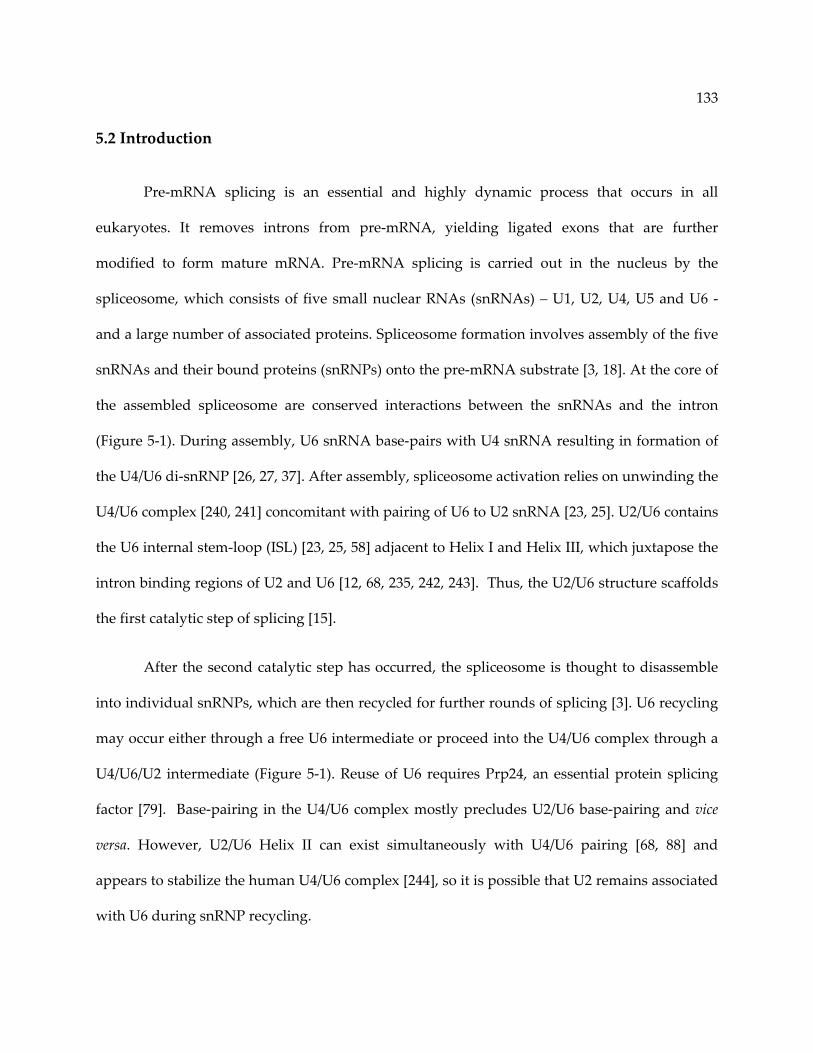
133
5.2 Introduction
Pre‐mRNA splicing is an essential and highly dynamic process that occurs in all
eukaryotes. It removes introns from pre‐mRNA, yielding ligated exons that are further
modified to form mature mRNA. Pre‐mRNA splicing is carried out in the nucleus by the
spliceosome, which consists of five small nuclear RNAs (snRNAs) – U1, U2, U4, U5 and U6 ‐
and a large number of associated proteins. Spliceosome formation involves assembly of the five
snRNAs and their bound proteins (snRNPs) onto the pre‐mRNA substrate [3, 18]. At the core of
the assembled spliceosome are conserved interactions between the snRNAs and the intron
(Figure 5‐1). During assembly, U6 snRNA base‐pairs with U4 snRNA resulting in formation of
the U4/U6 di‐snRNP [26, 27, 37]. After assembly, spliceosome activation relies on unwinding the
U4/U6 complex [240, 241] concomitant with pairing of U6 to U2 snRNA [23, 25]. U2/U6 contains
the U6 internal stem‐loop (ISL) [23, 25, 58] adjacent to Helix I and Helix III, which juxtapose the
intron binding regions of U2 and U6 [12, 68, 235, 242, 243]. Thus, the U2/U6 structure scaffolds
the first catalytic step of splicing [15].
After the second catalytic step has occurred, the spliceosome is thought to disassemble
into individual snRNPs, which are then recycled for further rounds of splicing [3]. U6 recycling
may occur either through a free U6 intermediate or proceed into the U4/U6 complex through a
U4/U6/U2 intermediate (Figure 5‐1). Reuse of U6 requires Prp24, an essential protein splicing
factor [79]. Base‐pairing in the U4/U6 complex mostly precludes U2/U6 base‐pairing and vice
versa. However, U2/U6 Helix II can exist simultaneously with U4/U6 pairing [68, 88] and
appears to stabilize the human U4/U6 complex [244], so it is possible that U2 remains associated
with U6 during snRNP recycling.

134
Several mutations that alter the relative stabilities of the yeast U6 ISL and the U4/U6
helices result in cold sensitive growth. For example, substitution of U4‐G14 with either a C or a
U, which disrupts a G‐C pair in Stem II (Figure 5‐1), is lethal at 22°C or below [245]. A genome‐
wide selection for spontaneous suppressors of the cold sensitive growth of U4‐G14C/U yielded
four independent mutations in U6 RNA, including U6‐A91G, which is downstream of U4/U6
Stems I and II but adjacent to U2/U6 Helix II (Figure 5‐1) [245]. Likewise, substitution of U6‐A62
with G, which converts an A‐C mismatch at the base of the ISL to a stable G‐C pair, results in a
cold sensitive growth defect (Fortner et al., 1994).
Here we investigate the structural basis for mutations in U6 snRNA and the mechanism
by which they act as suppressors of cold sensitive phenotypes. We show that mutations
associated with cold sensitivity induce alternate folds of the U2/U6 RNA complex.
Furthermore, by combining two mutations with opposing structural defects, the wild‐type
U2/U6 secondary structure and normal growth are restored. A U6 mutation (A91G)
simultaneously stabilizes the U2/U6 complex and destabilizes a U6 structure that is mutually
exclusive with U4/U6 pairing. Strikingly, U6‐A91G rescues lethality resulting from two
mutations that destabilize the U4/U6 complex. The resulting triple mutant strain grows
normally but exhibits a drastic shift in levels of spliceosome assembly intermediates, including
decreased levels of U4/U6 RNA complex and di‐snRNP as well as a novel U2/U6 snRNP. The
U2/U6 snRNP is detectable in wild‐type, but appears to be stabilized in the triple mutant strain.
Our data provide the first evidence that a U2/U6 snRNP is an intermediate in spliceosome
recycling, and further suggests that stable pairing of U4 and U6 RNAs is not essential for
spliceosome assembly.

135
Figure 5‐1. U6 participates in multiple structures throughout the splicing cycle.
U4 is shown in yellow, U6 in red, U2 in purple and pre‐mRNA in gray. Essential elements of
each RNA structure and the corresponding spliceosomal subcomplexes are labeled. Positions of
mutations used in this study are indicated with black arrows.

136
5.3 Materials and Methods
5.3.1 NMR sample preparation
DNA templates for all 83 nucleotide constructs were prepared through phosphorylation
and ligation of complementary, overlapping oligonucleotides (Integrated DNA Technologies)
into pUC19 vector (New England Biolabs). A BsaI restriction site was included at the end of the
template to allow for run‐off transcription after digestion with BsaI enzyme (NEB). RNA was
transcribed in vitro using purified His6‐tagged T7 RNA polymerase [156]. Nucleoside
triphosphate concentrations were adjusted stoichiometrically to the RNA sequence with the
lowest concentration at 5 mM. RNA samples were purified using denaturing 6%
polyacrylamide gel electrophoresis with 8 M urea. Impurities were removed by DEAE anion‐
exchange chromatography (BioRad), using a low salt buffer (20 mM Tris‐HCl, pH 7.6, 200 mM
sodium chloride) to wash the sample and a high salt buffer (20 mM Tris‐HCl, pH 7.6, 1.5 M
sodium chloride) to elute the RNA. Each sample was then heated to 90°C and cooled
immediately on ice. Samples were then dialyzed into 2 L of 20 mM sodium acetate, pH 6.0, for
24 hours at 4°C and concentrated for NMR experiments using Millipore Amicon© Ultra
centrifugal filter devices (10 KDa molecular weight cutoff).
5.3.2 NMR spectroscopy
All spectra were obtained on Bruker Avance DMX 700 or 750 MHz spectrometers at the
National Magnetic Resonance Facility at Madison. The spectrometers were equipped with
cryogenic single z‐axis gradient HCN probes. Exchangeable resonances were assigned by 1H‐1H
2D NOESY with a mixing time of 100 ms and 1H‐15N TROSY‐HSQC in 90% H2O, 10% D2O with

137
20 mM sodium acetate, pH 6.0 at 10°C. 1H 1D variable temperature NMR was performed in 10
mM potassium phosphate, pH 7.0.
5.3.3 Temperature controlled UV spectrophotometry
UV spectrophotometry was performed using a using a Varian Cary 100‐Bio. All 83 nt
RNA molecules were diluted to 0.6‐0.8 nM in 10 mM potassium phosphate, pH 7.0, 100 mM
potassium chloride. An identical cell containing the same buffer was used to monitor
temperature. A matched reference cell containing buffer was used to collect background
absorbance. Each sample was heated from 10°C to 95°C quickly (10°C/min) and cooled again
without collecting data. The samples were then heated and cooled slowly (1°C/min) 8 times
while monitoring the absorbance at 258 nm. Individual data sets were compared to check for
RNA degradation and hysteresis and then averaged. Each experiment was conducted in
triplicate.
5.3.4 Strain construction and in vivo growth studies
U6‐A91G and U6‐A62G/A91G were introduced into the U6 RNA gene (SNR6) in the
plasmid pUC19 (New England Biolabs) using the Quikchange protocol (Stratagene). The gene
was sub‐cloned into the pRS314 vector. Sub‐cloning was achieved by first amplifying the SNR6
gene by PCR and then digesting the amplicon with EcoRI and BamHI restriction enzymes
(Promega). The digested amplicon was ligated into pRS314 using T4 DNA ligase (Promega).
Preparation of pRS313‐U4, pRS313‐U4‐G14C, pRS314‐U6 and pRS314‐U6‐A62G has been
described previously [58, 246]. The desired U4 and U6 alleles were co‐transformed into S.
cerevisiae strain CJM000 as described previously [247, 248]. Transformants were then streaked
onto SC medium containing 0.75 mg/ml 5‐fluoroorotic acid (5‐FOA) to select for strains
containing only the newly acquired alleles. Growth phenotypes were tested by spotting 10‐fold

138
serial dilutions, starting with OD600 = 1.0 of each strain onto solid YEPD medium and incubating
at 16°C, 25°C, 30°C and 37°C.
5.3.5 Whole cell RNA extraction, solution hybridization and Northern analysis
Whole cell RNA extract was prepared from each strain under non‐denaturing conditions
as previously described [78]. 30 ml YEPD cultures of each strain were incubated, shaking, at
30°C until reaching an OD600 of 0.6‐0.8. Enough culture to yield 10 OD600 units were harvested
and then lysed at 4°C using 0.5 mm glass beads in a phenol/chloroform mixture equilibrated to
pH 7.5. RNA was extracted in aqueous buffer containing 200 mM Tris, pH 7.5, 100 mM EDTA
and 500 mM NaCl. Extracted RNA was ethanol precipitated and resuspended in ddH2O for
storage.
DNA oligomers used for solution hybridization and Northern analysis are as follows:
U4‐14B: 5’‐AGGTATTCCAAAAATTCCC‐3’ [78]; U1‐SH: 5’‐CCGTATGTGTGTGTGACC‐3’ and
U6‐SH: 5’‐ATTGTTTCAAATTGACCAAAT‐3’ [249]; U2seq (solution hybridization): 5’‐
GTGTATTGTAACAAATTAAAAGG‐3’; U5B: 5’‐AAGTTCCAAAAAATATGGCAAGC‐3’;
SRU2 (Northern analysis): 5’‐CAGATACTACACTTG‐3’ [237]. Oligomers were 5’‐end labeled
with 32P using OptiKinase (USB).
Solution hybridization was performed as previously described [78]. Total RNA from
each strain was hybridized to the desired oligomer in 50 mM Tris, pH 7.5, 1 mM EDTA, 150 mM
NaCl, for 15 minutes at 37°C. Following hybridization, the RNA extracts were analyzed by non‐
denaturing 9% PAGE (29:1 acrylamide:bisacrylamide) in 50 mM TBE at 4°C. Gels were dried
under vacuum and exposed to a phosphorimager screen, which was then imaged using a
Typhoon FLA 9000 at 800 V.

139
Whole cell RNA extract was also analyzed by Northern analysis. The RNA was
separated by non‐denaturing 6% PAGE (29:1 acrylamide:bisacrylamide) in 50 mM TBE at 4°C.
The gel was then soaked in 8.3 M urea, 0.1% SDS, 60 mM Tris, pH 6.8 for 10 min to denature
RNA. RNA was transferred to a Hybond‐N membrane at 10 V/cm for 12‐16 h at 4°C in 12 mM
Tris, pH 8, 6 mM sodium acetate, 0.3 mM EDTA and then crosslinked to the membrane using a
Stratagene Stratalinker at 1200 mJ for 90 seconds. Membranes were prehybridized in 6X SSC,
0.2% SDS, 10X Denhardt’s solution for 1.5‐2 h at 65°C and hybridized to 32P‐labeled
oligonucleotide (~1X10⁶ cpm/ml) in 6X SSC, 0.2% SDS, 5X Denhardt’s solution for 16‐18 h at
25°C. Following hybridization, membranes were washed in 6X SSC, 0.2% SDS twice for 10 min
at 25°C and once for 10 min at 37°C.
5.3.6 Splicing extract preparation, snRNP analysis and spliceosome assembly
Extracts were prepared from wild type or U6‐A62G/A91G, U4‐G14U strains using an
adaptation of the liquid nitrogen method [250]. 2 L of each strain were grown until OD600 = 2‐4
in YEPD. Cells were harvested by centrifugation and washed with AGK buffer (10 mM HEPES,
pH 7.9, 1.5 mM MgCl2, 200 mM KCl, 10% glycerol). Cells were resuspended in 0.4 volumes
AGK buffer with 1 mM PMSF and then frozen in droplets in liquid nitrogen. The frozen
droplets were ground to a fine powder 5 x 3 min at 10 Hz in a Retsch MM400 Mixer Mill in 50
ml stainless steel jars with a 2.5 cm stainless steel ball, cooling the jars for 3 min in liquid
nitrogen between cycles. The powder was thawed in a centrifuge tube rapidly at 25°C and
centrifuged at 34,800 x g for 30 min at 4°C in a 70.1 TI rotor. Samples were frozen in 100 μl
aliquots in liquid nitrogen and stored at ‐80°C. Protein concentration as determined by Bradford
assay using BSA as a standard was determined to be 15‐25 mg/ml. snRNP formation was
analyzed as previously described [79].

140
Splicing extracts were incubated with or without 1 mM ATP in 2.5 mM MgCl2, 3% PEG
8000, 60 mM KPO4 pH 7.0, 2 mM spermidine for either 30 min at 30°C or 15 min at 23°C. For
RNase H digestion, extracts were incubated under the 30°C conditions with 20 ng/μl U2seq
oligonucleotide and 1 mM ATP. Deproteinized RNA was isolated from splicing extracts using
phenol/chloroform as described above for whole cell RNA extract. Samples were analyzed as
previously described [79] by non‐denaturing 4% PAGE (80:1 acrylamide:bisacrylamide), 50 mM
Tris, 50 mM glycine, 2 mM MgCl2 (10 V/cm, 5 h) at 4°C. RNA was transferred to a Hybond‐N
membrane (Amersham) 16‐18 h at 25 V (1500 mA) in 0.5 M NaPO4, pH 6.5 at 4°C. RNA was
crosslinked to the membrane, and membranes were probed and imaged as described above.
Spliceosome assembly assays were performed as previously described [240, 248] in 100
mM potassium phosphate, pH 7.3, 3% PEG 8000, 2.5 mM MgCl2, 1 mM DTT and 2 mM ATP,
40% splicing extract and 0.4 nM 5’‐32P‐labeled, capped, RP51a pre‐mRNA substrate. Reactions
were stopped at the specified time by adding 1 volume of 60 mM potassium phosphate, pH 7.0,
3 mM MgCl2, 3% PEG, 8% glycerol and 0.8 mg/ml heparin (2 μg per μl splicing extract) and
analyzed by 4% non‐denaturing PAGE (80:1 acrylamide:bisacrylamide) in 50 mM TBE at 10‐30
V/cm. The gel was dried under vacuum and exposed to a phosphorimager screen for 18‐24
hours, which was then imaged on a Typhoon FLA 9000 at 800 V.

141
5.4 Results
5.4.1 Analysis of the U2/U6 RNA structure
To investigate the effects of mutations on the structure of the U2/U6 complex, we
designed an 83‐nucleotide RNA construct that contains yeast U2/U6 intermolecular Helices I
and II and the U6 ISL (Figure 5‐2A). The unaltered RNA will be referred to as “wild‐type”. The
secondary structure of the wild‐type RNA was analyzed by NMR and assigned by 1H‐1H 2D
NOESY and 1H‐15N 2D TROSY‐HSQC. In the wild‐type RNA, base‐pairing is observed in the U6
ISL, Helix I and Helix II (Figure 5‐2B). Chemical shifts are consistent with previous studies that
used related constructs [95, 96]. Six broad uracil resonances in dynamic exchange are observed
in the wobble pair region of the proton spectrum (~11 ppm; Figure 5‐2B, C). These resonances
give strong NOE cross‐peaks to each other and are consistent with transient formation of
intermolecular U‐U wobble pairs (Figure 5‐2A). Pairing in this region is consistent with
previously detected cross‐links [216] and structural studies [95]. Thus, the observed secondary
structure is a three‐helix junction as previously predicted [23] and observed by SAXS and NMR
[95]. We analyzed the thermodynamic stability of the wild‐type RNA, which has a melting
temperature of 49°C in 100 mM potassium chloride and displays one predominantly
cooperative folding/unfolding transition (Figure 5‐3A, B). NMR data collected at 10°C
increments from 10°C to 50°C are consistent with this result (Figure 5‐5A).

142
Figure 5‐2. The wild‐type U2/U6 83 nt RNA forms a three‐helix junction.
A. Secondary structure of the wild‐type U2/U6 RNA. A schematic of U2/U6 as portrayed in
Figure 5‐1 is inset. The detailed secondary structure is color‐coded according to secondary
structure as follows: Helix I (green), Helix II (purple), and U6 ISL (blue). Observed base‐pairs
are indicated with lines or circles for non‐canonical pairs. B. 2D 1H‐1H NOESY of wild‐type
U2/U6 RNA acquired in 20 mM sodium acetate, pH 6, 90% H2O, 10% D2O at 10°C. Connecting
lines and 1H 1D peaks are labeled based on NOESY assignments are color‐coded based on
secondary structure as above. U‐U wobble pair resonances are shown enlarged in the red box.
C. Confirmation of U‐U wobble pairs by 1H‐15N TROSY‐HSQC. The U2/U6 WT RNA was
specifically 15N‐U labeled allowing for detection of only uracil imino protons. Resonances
corresponding to the U‐U wobble pairs are clearly observable in the range of 10.5‐11.2 ppm (red
box).

143

144
5.4.2 U6‐A62G stabilizes a four‐helix junction in the U2/U6 complex
The cold sensitivity of the U6‐A62G mutant is due at least in part to hyperstabilization of
the U6 ISL, via substitution of an A‐C mismatch with a stable G‐C base‐pair at the base of the
ISL [58]. In the U2/U6‐A62G RNA the U6 ISL is extended by three base pairs, disrupting U2/U6
Helix Ib (Figure 5‐4A). Additionally, we observe formation of U2 Stem I [96, 99]. Helix Ia and
Helix II form in U2/U6‐A62G, although fewer base‐pairs are detected in Helix II than in wild‐
type (Figure 5‐4A). The resulting conformation is a four‐helix junction, which we have
previously observed in other U2/U6 constructs [96]. The four‐helix junction is an alternate fold
predicted to be close in free energy to the three‐helix junction [100] and these conformations
may exist in equilibrium [219].
The overall hyperchromicity of U2/U6‐A62G is very similar to wild‐type (Figure 5‐3A),
indicating that the extent of base‐stacking in the two RNA molecules is similar; however, in
contrast to wild‐type, the A62G variant unfolds in two transitions (Figure 5‐3B). One melting
transition is centered at 51°C and corresponds to both Helix II and U2 Stem I, while the second
transition corresponds to the ISL at 65°C (Figure 5‐3B and Figure 5‐5D). The higher melting
temperature of the U6‐A62G ISL in this RNA is consistent with previous studies of the ISL
containing the A62G mutation [101]. Therefore, U6‐A62G hyperstabilizes the U6 ISL and
substantially alters the conformation of the U2/U6 complex.
5.4.3 U6‐A91G destabilizes the U6 ISL by extending Helix II
The U6‐A91G mutation suppresses the cold sensitivity of U4‐G14C [245], yet it lies
outside the U4/U6 pairing region. Because U6‐A91 is adjacent to U2/U6 Helix II (Figure 5‐1), we
hypothesized that the mechanism of suppression of U4‐G14C involves alteration of the U2/U6

145
secondary structure. Strikingly, the U2/U6‐A91G RNA does not form most of the U6 ISL (Figure
5‐4B). Three base pairs in the upper U6 ISL can be identified based on chemical shift (Table 5‐1);
however, the majority of base pairs in the ISL helix are clearly not present. All base‐pairs in
Helix II are observed, including a mutation‐induced base‐pair between U6‐G91 and U2‐C14
(Figure 5‐4B). Helix Ia is also fully base‐paired in this variant. Three NOE cross‐peaks indicate
formation of U‐U wobble pairs (Figure 5‐4B, inset) at the same chemical shift as the wild‐type
RNA. However, the exchange broadening observed in the wild‐type RNA is not present,
indicating that the U‐U wobble pairs are more stable in the A91G variant, likely due to the
stabilizing effects of the adjacent mutation.
The U2/U6‐A91G mutant exhibits a highly cooperative melting transition centered at
53°C (Figure 5‐3B) that corresponds to dissociation of Helices I and II and the upper ISL as
determined by NMR (Figure 5‐5A, B). The higher melting temperature of Helix II in U2/U6‐
A91G confirms the presence of additional base‐pairs. Furthermore, the hyperchromicity of the
U2/U6‐A91G RNA is significantly greater than that of wild‐type (Figure 5‐3A), which, along
with the observed cooperativity, indicates a higher overall degree of base‐pairing and stacking.
We note that the stabilized U‐U wobble pairs are adjacent to U2/U6 sequences that can form a
potential helix (Helix IIb) would invade the U6 ISL (Figure 5‐4B). Indeed, this extension of
Helix II is predicted to form based on free energy minimization [161]. However, like the U6 ISL,
the Helix IIb base pairs are not observed in the NMR spectra. A possible explanation consistent
with increased hyperchromicity and pairing observed by NMR is that the U6 ISL and Helix IIb
are in dynamic exchange in this RNA.
In order to test the hypothesis that Helix IIb destabilizes the U6 ISL in a dynamic
exchange process, we stabilized Helix IIb by mutation of U6‐A83 to a G, thereby changing a

146
predicted AC wobble pair in the middle of this helix to a GC pair (Figure 5‐6A). The U6‐A83G
mutation is viable and causes no growth defects [63], and could potentially still form the U6 ISL
by replacing a UA pair in the lower ISL with an energetically similar UG wobble pair. NMR
analysis of the U2/U6‐A83G RNA reveals Helix IIb rather than the ISL (Figure 5‐6A), along with
stable U‐U wobble pairs at the same chemical shift as those detected in the U2/U6‐A91G and
wild‐type RNAs (Figure 5‐6B and Table 5‐1). The hyperchromicities of U2/U6‐A91G and A83G
are nearly identical, indicating highly similar extents of base‐pairing (Figure 5‐6C). The melting
temperature of Helix II is slightly higher in the U2/U6‐A83G RNA (55°C) than in the U2/U6‐
A91G RNA (53°C), consistent with increased stabilization of Helix IIb (Figure 5‐6D). In addition,
the A83G mutant exhibits a hyperchromic transition at 37°C not seen with the wild‐type or
A91G mutant (Figure 5‐6D), which can be assigned to the stabilized U‐U wobble pairs in Helix
IIb (Figure 5‐6C). Therefore, both the U6‐A91G and U6‐A83G mutants form Helix IIb, which
invades the lower U6 ISL. Since the U6 ISL competes with U4/U6 pairing, disruption of the ISL
provides a potential mechanism for suppression of U4‐G14C by U6‐A91G [245].
5.4.4 U6‐A91G counteracts stabilization of the U6 ISL by U6‐A62G in vitro
Due to the opposing effects of the U6‐A62G and A91G mutations, which stabilize and
destabilize the U6 ISL, respectively, we hypothesized that inclusion of both mutations would
restore the thermodynamic balance between the U6 ISL and Helix II, resulting in a
cooperatively folded RNA structure that resembles wild‐type. Indeed, when both mutations are
incorporated into U2/U6, base‐pairing is detected in the U6 ISL, Helix II, Helix Ia and Helix Ib
(Figure 5‐4C). Thus, the A62G mutation prevents disruption of the U6 ISL by A91G, and the
A91G mutation prevents disruption of Helix Ib and formation of U2 Stem I by A62G (Figure

147
5‐4C and Table 5‐1). Consequently, the U6‐A62G/A91G RNA has a wild‐type fold, as
hypothesized.
The U2/U6‐A62G/A91G RNA is more stable than wild‐type (Figure 5‐3B and Figure
5‐5E) and unfolds in three overlapping transitions. The highest temperature transition
corresponds to the stabilized U6 ISL, the middle transition to stabilized Helix II and the lowest
melting transition to Helix I. Thus, the combined effects of the A62G and A91G mutations also
restore the near‐cooperative folding that was lost in the A62G mutant (compare A62G to
A62G/A91G, Figure 5‐3B).

148
Figure 5‐3. Stability of the minimal U2/U6 RNA and variants.
A. Melting profiles of wild‐type, U6‐A62G, U6‐A91G and U6‐A62G/A91G RNAs in 20 mM
potassium phosphate, pH 7. UV absorbance at 258 nm was normalized to the value at 10°C.
Experiments conducted in triplicate were averaged and error bars denote standard deviation. B.
First derivative of normalized hyperchromicity for the RNAs listed in (A). Data were smoothed
over three points.

149
Figure 5‐4. U6‐A91G abolishes U6 ISL formation and rescues U6‐A62G in vitro.
A. 1H‐1H 2D NOESY of U6‐A62G RNA acquired in 20 mM sodium acetate, pH 6, 90% H2O, 10%
D2O at 10°C. Connecting lines are color‐coded according to structure as follows: Helix I (green),
Helix II (purple), U6 ISL (blue) and U2 Stem I (orange). 1H 1D resonances are labeled based on
NOESY assignments and are color‐coded according to secondary structure as above. B.
Secondary structure of the U6‐A91G RNA. Observed base‐pairs are indicated with lines.
Possible U‐U wobble pairs are indicated with gray circles. Base‐pairs inferred by chemical shift
agreement are shown as dashed lines. Residues are color‐coded according to secondary
structure as in Figure 5‐2. U‐U wobble pairs are shown enlarged in the red box. Very weak NOE
cross‐peaks are depicted by a small dashed circle. Resonance splitting due to addition of a non‐
template nucleotide at the 3’ end of the RNA is indicated by a star. C. Secondary structure of
U6‐A62G/A91G RNA, color‐coded and labeled as above.

150
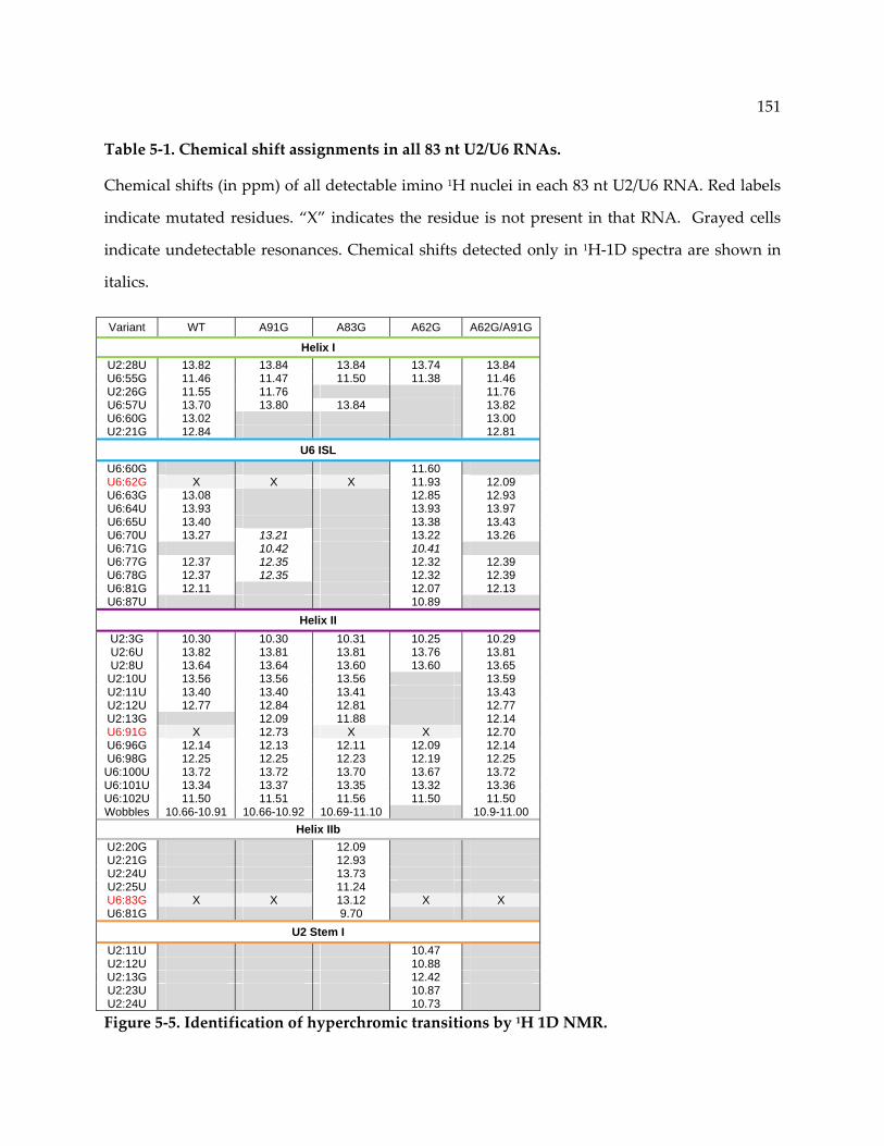
151
Table 5‐1. Chemical shift assignments in all 83 nt U2/U6 RNAs.
Chemical shifts (in ppm) of all detectable imino 1H nuclei in each 83 nt U2/U6 RNA. Red labels
indicate mutated residues. “X” indicates the residue is not present in that RNA. Grayed cells
indicate undetectable resonances. Chemical shifts detected only in 1H‐1D spectra are shown in
italics.
Variant WT A91G A83G A62G A62G/A91G
Helix I U2:28U 13.82 13.84 13.84 13.74 13.84 U6:55G 11.46 11.47 11.50 11.38 11.46 U2:26G 11.55 11.76 11.76 U6:57U 13.70 13.80 13.84 13.82 U6:60G 13.02 13.00 U2:21G 12.84 12.81
U6 ISL U6:60G 11.60 U6:62G X X X 11.93 12.09 U6:63G 13.08 12.85 12.93 U6:64U 13.93 13.93 13.97 U6:65U 13.40 13.38 13.43 U6:70U 13.27 13.21 13.22 13.26 U6:71G 10.42 10.41 U6:77G 12.37 12.35 12.32 12.39 U6:78G 12.37 12.35 12.32 12.39 U6:81G 12.11 12.07 12.13 U6:87U 10.89
Helix II U2:3G 10.30 10.30 10.31 10.25 10.29 U2:6U 13.82 13.81 13.81 13.76 13.81 U2:8U 13.64 13.64 13.60 13.60 13.65
U2:10U 13.56 13.56 13.56 13.59 U2:11U 13.40 13.40 13.41 13.43 U2:12U 12.77 12.84 12.81 12.77 U2:13G 12.09 11.88 12.14 U6:91G X 12.73 X X 12.70 U6:96G 12.14 12.13 12.11 12.09 12.14 U6:98G 12.25 12.25 12.23 12.19 12.25 U6:100U 13.72 13.72 13.70 13.67 13.72 U6:101U 13.34 13.37 13.35 13.32 13.36 U6:102U 11.50 11.51 11.56 11.50 11.50 Wobbles 10.66-10.91 10.66-10.92 10.69-11.10 10.9-11.00
Helix IIb U2:20G 12.09 U2:21G 12.93 U2:24U 13.73 U2:25U 11.24 U6:83G X X 13.12 X X U6:81G 9.70
U2 Stem I U2:11U 10.47 U2:12U 10.88 U2:13G 12.42 U2:23U 10.87 U2:24U 10.73
Figure 5‐5. Identification of hyperchromic transitions by 1H 1D NMR.
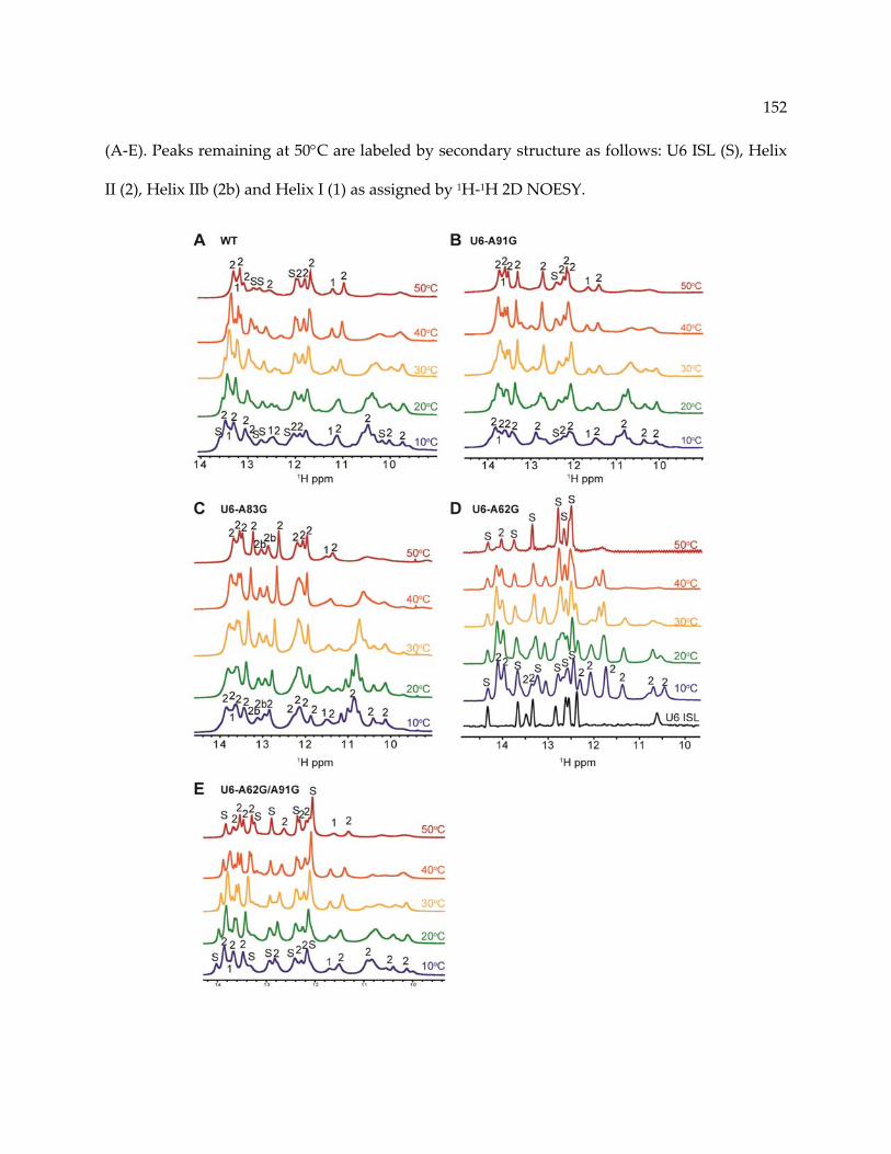
152
(A‐E). Peaks remaining at 50°C are labeled by secondary structure as follows: U6 ISL (S), Helix
II (2), Helix IIb (2b) and Helix I (1) as assigned by 1H‐1H 2D NOESY.
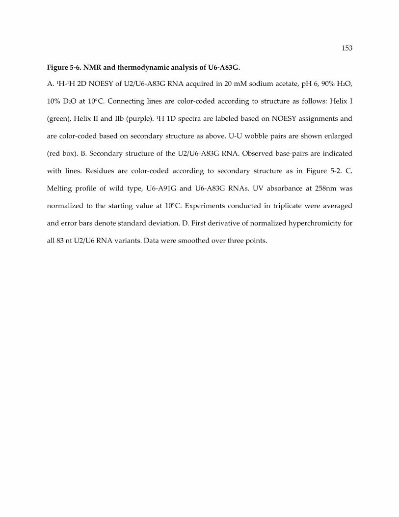
153
Figure 5‐6. NMR and thermodynamic analysis of U6‐A83G.
A. 1H‐1H 2D NOESY of U2/U6‐A83G RNA acquired in 20 mM sodium acetate, pH 6, 90% H2O,
10% D2O at 10°C. Connecting lines are color‐coded according to structure as follows: Helix I
(green), Helix II and IIb (purple). 1H 1D spectra are labeled based on NOESY assignments and
are color‐coded based on secondary structure as above. U‐U wobble pairs are shown enlarged
(red box). B. Secondary structure of the U2/U6‐A83G RNA. Observed base‐pairs are indicated
with lines. Residues are color‐coded according to secondary structure as in Figure 5‐2. C.
Melting profile of wild type, U6‐A91G and U6‐A83G RNAs. UV absorbance at 258nm was
normalized to the starting value at 10°C. Experiments conducted in triplicate were averaged
and error bars denote standard deviation. D. First derivative of normalized hyperchromicity for
all 83 nt U2/U6 RNA variants. Data were smoothed over three points.
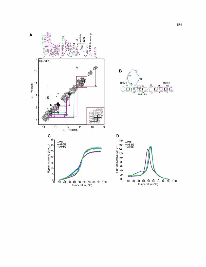
154

155
5.4.5 Stability of U2/U6 in vitro correlates with growth phenotypes in vivo
Based on our structural and thermodynamic data, we hypothesized that U6‐A91G may
be able to rescue the cold sensitive phenotype of U6‐A62G in vivo. Alternatively, overall
hyperstabilization of the U2/U6 complex may result in a growth defect or cell death if the
necessary structural rearrangements (Figure 5‐1) are inhibited. Indeed, U6‐A91G suppresses the
cold sensitive phenotype of U6‐A62G (Figure 5‐7A). This result suggests that stabilization of the
U2/U6 four‐helix junction conformation is responsible for the cold sensitive growth defect of
U6‐A62G, and that U6‐A91G can suppress formation of this conformation in vivo as well as in
vitro. In contrast to U6‐A62G, the U6‐A91G strain exhibits wild‐type growth. This finding
suggests that, although A91G destabilizes the U6 ISL in vitro, the ISL can still form in vivo.
Alternatively, the lower ISL could be non‐essential, or redundant with U2/U6 Helix IIb.
Destabilization of U4/U6 by U4‐G14U concomitantly with stabilization of the U6 ISL by
U6‐A62G should be highly detrimental to yeast as both of these mutations result in cold
sensitivity and decreased levels of U4/U6 in vivo [60, 248]. Indeed, attempts to construct a strain
containing both U6‐A62G and U4‐G14U yielded no transformants, suggesting that these
mutations result in a dominant lethal phenotype. Strikingly, addition of the U6‐A91G mutation
suppresses the apparent dominant lethality of U6‐A62G and U4‐G14U in combination, as well
as the cold sensitivity of each individual mutation (Figure 5‐7A).
5.4.6 Apparent loss of U4/U6 pairing in a triple mutant strain
To assess the effect of these mutations on the efficiency of U4/U6 complex assembly in
vivo, total RNA was extracted from each strain under non‐denaturing conditions and analyzed
by solution hybridization (Figure 5‐7B, C) [251]. As shown previously [58, 248], in wild‐type

156
cells about 75‐85% of U4 RNA is paired with U6 RNA, and both U6‐A62G and U4‐G14U
decrease the fraction of U4 RNA base‐paired to U6 RNA.
Consistent with the absence of a growth defect, U6‐A91G alone has no effect on the
fraction of U4 paired with U6. U6‐A91G does increase U4/U6 complex formation in the presence
of U6‐A62G (Figure 5‐7C), in agreement with the observed suppression. However, U4/U6 levels
in the double mutant are still as low as in the cold sensitive U4‐G14U strain (Figure 5‐7C).
Although U6‐A91G strongly suppresses the cold sensitivity of U4‐G14U, it has only a modest
effect on the U4/U6 level in the U4‐G14U strain. Thus, there is not a good correlation between
phenotypic suppression by U6‐A91G and restoration of U4/U6 assembly.
Strikingly, we find that the strain with all three mutations contains no detectable U4/U6
complex (Figure 5‐7B), despite exhibiting near normal growth at all temperatures (Figure 5‐7A).
To ensure that U4/U6 is not dissociating during solution hybridization, we performed Northern
analysis of the RNA extracts to avoid subjecting them to elevated temperature (37°C) prior to
electrophoresis, as is done for solution hybridization (Figure 5‐8). A very small amount of
U4/U6 is detectable in the U6‐A62G/A91G, U4‐G14U strain (hereafter referred to as triple
mutant), indicating that the U4/U6 complex in this strain is highly unstable. Thus, suppression
of the lethal double mutant by U6‐A91G is not accompanied by restoration of wild‐type levels
of U4/U6 pairing. Nevertheless, both U4 RNA and the U4/U6‐annealing factor Prp24 are still
required in the triple mutant strain (Appendix I, Figure A1‐2A and Figure A1‐3), so U4 RNA
still has an essential function in this strain.

157
Figure 5‐7. U6‐A91G suppresses U4‐G14U and U6‐A62G, resulting in loss of U4/U6 complex.
A. 10‐fold serial dilutions starting at 1 OD600 of each strain were incubated on YEPD at indicated
temperatures. B. Solution hybridization of total RNA from each strain. Extracted RNA was
hybridized in vitro to a 32P labeled DNA oligomer complementary to U1 and U4 or U6 at 37°C
for 15 min then analyzed by 9% non‐denaturing PAGE at 4°C. C. Quantitative analysis of U4/U6
levels and total U4 levels as normalized to U1.

158
Figure 5‐8. Northern analysis of total RNA from all strains.
RNA was extracted under non‐denaturing conditions, separated by 6% non‐denaturing PAGE
and transferred to a Hybond‐N membrane. The membrane was probed for snRNA using 32P‐
labeled DNA oligonucleotides complementary to U1, U4 and U6. Quantitation was averaged
over four replicates and error bars represent standard error.

159
5.4.7 Stabilization of a novel U2/U6 snRNP
The near absence of U4/U6 RNA complex in the triple mutant strain suggests that only a
small fraction of U6 RNA molecules proceed through a U4/U6 assembly intermediate.
Alternatively, U4/U6 di‐snRNP may be a requisite intermediate, but lack stable base‐pairing
between U4 and U6 RNAs. To distinguish between these possibilities, we prepared whole‐cell
extracts from the wild‐type and triple mutant strains and analyzed their steady‐state snRNP
composition using non‐denaturing gel electrophoresis (Figure 5‐9). Extracts were incubated
with or without 2 mM ATP for 30 min at 30°C (lanes 1‐4) or 15 min at 23°C (lanes 5‐8) to sample
any dynamic changes in snRNP interactions.
Consistent with the observed loss of U4/U6 pairing, the triple mutant strain is essentially
devoid of U4/U6 di‐snRNP. Instead, the strain accumulates large amounts of free U4 snRNP (U4
probe, lanes 3 & 4) and free U6 snRNP and snRNA (U6 probe, lanes 3 & 4). In the triple mutant
strain, a much larger fraction of free U6 co‐migrates with the deproteinized RNA, suggesting
that one or more of the mutations disrupt binding of U6 snRNP proteins. Despite the complete
absence of U4/U6 di‐snRNP, the triple mutant strain contains detectable amount of U4‐U6‐U5
tri‐snRNP, albeit less than in the wild‐type strain. The U4/U6 complex in the tri‐snRNP must be
either unstably paired or unpaired, as the deproteinized triple mutant extract contains no
U4/U6 complex (lanes 11 and 12, U4 and U6 probes). Thus, incorporation of the U4 and U6
snRNPs in the tri‐snRNP may be mediated solely by individual contacts with U5 associated
proteins.
Another major finding is the identification of a novel U2/U6 snRNP, which appears
more abundant than the tri‐snRNP in the triple mutant extract (U6 probe, lane 10). This complex
is present in wild‐type extract in lower amounts (U6 probe, lane 9), but is less stable as it
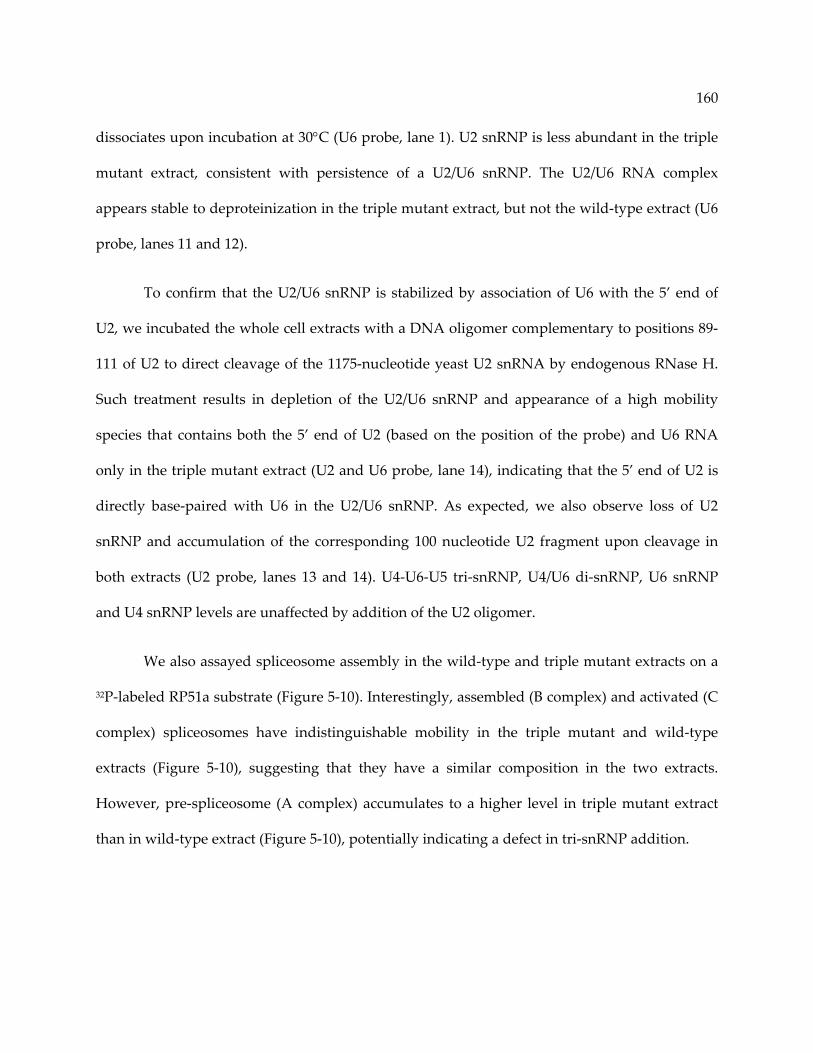
160
dissociates upon incubation at 30°C (U6 probe, lane 1). U2 snRNP is less abundant in the triple
mutant extract, consistent with persistence of a U2/U6 snRNP. The U2/U6 RNA complex
appears stable to deproteinization in the triple mutant extract, but not the wild‐type extract (U6
probe, lanes 11 and 12).
To confirm that the U2/U6 snRNP is stabilized by association of U6 with the 5’ end of
U2, we incubated the whole cell extracts with a DNA oligomer complementary to positions 89‐
111 of U2 to direct cleavage of the 1175‐nucleotide yeast U2 snRNA by endogenous RNase H.
Such treatment results in depletion of the U2/U6 snRNP and appearance of a high mobility
species that contains both the 5’ end of U2 (based on the position of the probe) and U6 RNA
only in the triple mutant extract (U2 and U6 probe, lane 14), indicating that the 5’ end of U2 is
directly base‐paired with U6 in the U2/U6 snRNP. As expected, we also observe loss of U2
snRNP and accumulation of the corresponding 100 nucleotide U2 fragment upon cleavage in
both extracts (U2 probe, lanes 13 and 14). U4‐U6‐U5 tri‐snRNP, U4/U6 di‐snRNP, U6 snRNP
and U4 snRNP levels are unaffected by addition of the U2 oligomer.
We also assayed spliceosome assembly in the wild‐type and triple mutant extracts on a
32P‐labeled RP51a substrate (Figure 5‐10). Interestingly, assembled (B complex) and activated (C
complex) spliceosomes have indistinguishable mobility in the triple mutant and wild‐type
extracts (Figure 5‐10), suggesting that they have a similar composition in the two extracts.
However, pre‐spliceosome (A complex) accumulates to a higher level in triple mutant extract
than in wild‐type extract (Figure 5‐10), potentially indicating a defect in tri‐snRNP addition.

161
Figure 5‐9. Stabilization of a U2/U6 snRNP in the triple mutant strain.
Ana
lysis of splicing extracts by no
n‐de
naturing 4% PAGE (80:1) w
ith or with
out 1 mM A
TP. Bo
ld labels indicate
snRN
Ps and narrow la
bels in
dicate snR
NA com
plexes. Vertical black bars indicate free U
2, U
4, U
5 an
d U6 snRN
Ps.
The U4/U6‐U5 tri‐snR
NP is in
dicated by an asterisk (*). Black bo
xes high
light stable U2/U6 RN
A com
plexes present in
the triple m
utan
t strain. Extracts were de
proteinized by pheno
l/chloroform extraction (la
nes 11‐12), leaving only RN
A
complexes. DNA olig
omer com
plem
entary to po
sitio
ns of 89‐111 of U2 RN
A w
as add
ed (lanes 13‐14) to prom
ote
RNase H cleavage of U2.
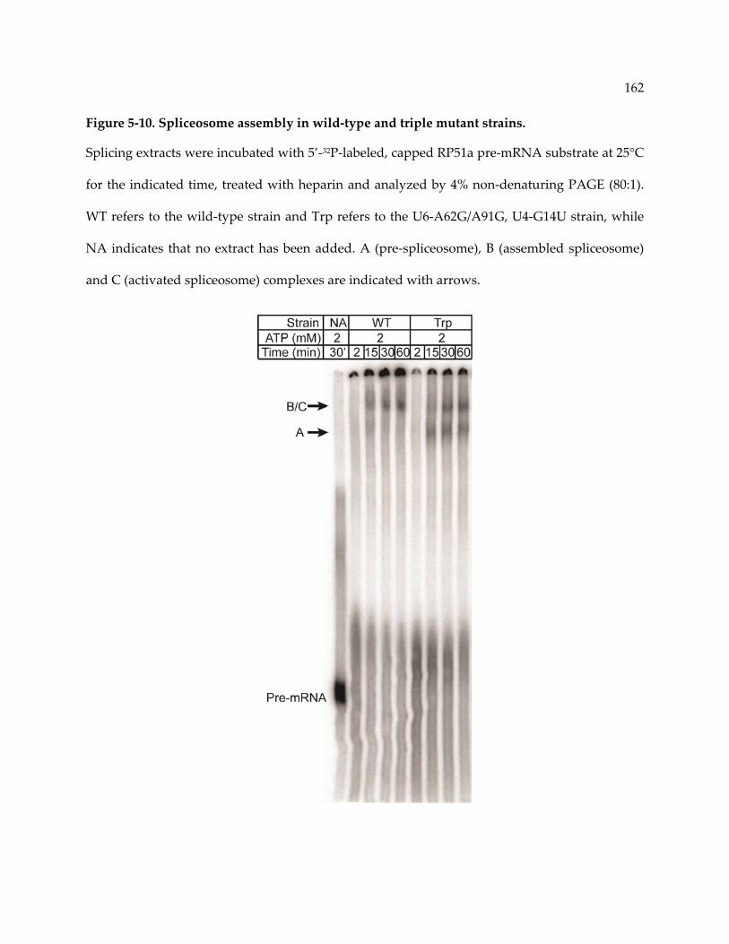
162
Figure 5‐10. Spliceosome assembly in wild‐type and triple mutant strains.
Splicing extracts were incubated with 5’‐32P‐labeled, capped RP51a pre‐mRNA substrate at 25°C
for the indicated time, treated with heparin and analyzed by 4% non‐denaturing PAGE (80:1).
WT refers to the wild‐type strain and Trp refers to the U6‐A62G/A91G, U4‐G14U strain, while
NA indicates that no extract has been added. A (pre‐spliceosome), B (assembled spliceosome)
and C (activated spliceosome) complexes are indicated with arrows.

163
5.5 Discussion
Here, we present evidence for a novel U2/U6 snRNP recycling intermediate that is
transient unless the U4/U6 complex is destabilized. We initially considered the possibility that
disruption of the U6 ISL in the U2/U6‐A91G complex facilitates pairing of U6 or U6‐A62G with
U4‐G14U/C. This mechanism predicts the existence of a stabilized U4/U6/U2 tri‐snRNA
complex in the triple mutant extract, yet we detect no such complex. Instead we detect a U2/U6
snRNP that contains a stabilized U2/U6 RNA complex and a U4‐U6‐U5 snRNP that co‐migrates
with the wild‐type tri‐snRNP, but lacks stable interaction between U4 and U6 RNAs. Given that
we also observe a U2/U6 snRNP with the same mobility in a wild‐type strain, it is likely to be a
normal intermediate in snRNP recycling.
5.5.1 Stabilization of alternative snRNA conformations
Single‐nucleotide substitutions have a dramatic impact on the stability of U6 containing
complexes. Previous studies have demonstrated that disruption of a single G‐C pair in U4/U6
Stem II by U4‐G14C/U decreases the dissociation temperature of the endogenous complex from
~55°C to ~43°C and results in decreased levels of U4/U6 complex [245, 248]. Additionally,
mutation of U6‐A62 to a G stabilizes the U6 ISL and decreases U4/U6 levels nearly 6 fold [60].
Thus, single nucleotide changes in U6 sequence may shift the distribution of conformations in
the folding landscape of these complexes (Figure 5‐11A).
We find that U6‐A91G destabilizes the highly conserved U6 ISL in vitro and alters the
stability of the U2/U6 complex, resulting in dynamic exchange between the U6 ISL and Helix
IIb. We propose that this dynamic exchange lowers the energy barrier for unwinding the U6 ISL
(Figure 5‐11A). Consistent with our findings, the presence of a DNA oligomer that mimics

164
U2/U6 Helix II is stabilizing to the human U4/U6 complex [244]. Conversely, U6‐A62G
stabilizes a four‐helix junction in the context of U2/U6, thereby precluding formation of the
essential Helix Ib structure [23, 97]. The distal U6‐A91G mutation can compensate for U6‐A62G
both structurally and functionally, suggesting that the three‐helix junction must be maintained
for splicing to proceed efficiently. Therefore, the sequence of U6 is essential not only for the role
it may play in catalysis, but also to maintain structural stability and prevent competing U2/U6
structures.
The importance of the stability of U2/U6 Helix II has been inferred from other functional
studies. Disruption of two out of three base‐pairs in Helix Ib does not result in a growth defect;
however, the same mutations are lethal when base‐pairing in Helix II is destabilized [252]. This
result suggests that Helix Ib itself is not essential for catalysis but may work together with Helix
II to maintain the structure of the U2/U6 three‐helix junction. Our observations indicate that
Helix II acts to destabilize the extended U6 ISL and U2 Stem I, which contribute to the alternate
four‐helix junction conformation. Therefore, prevention of the four‐helix junction may be more
important for U2/U6 function than formation of a stable Helix Ib.
The human U2/U6 complex is thought to form a four‐helix junction based on genetic
studies [25]. However, the competition between the three and four‐helix junction conformations
of U2/U6 described in this study is likely to be relevant in the human spliceosome as well. The
importance of Helix II is well established in human U2/U6, as mutations in the Helix II region of
U2 block splicing and are rescued by compensatory mutations in U6 [202]. Additionally,
hyperstabilization of U2 Stem I inhibits splicing in the human U2 sequence, likely due to
disruption of pairing in Helix Ia and Helix II [253]. The human U2/U6 sequence has the capacity
to form intermolecular interactions adjacent to Helix II similar to the Helix IIb structure we
165
detect in the S. cerevisiae sequence. Human Helix II is adjacent to two wobble pairs (G‐U and U‐
C), followed by a series of potential A‐U pairs. As with yeast Helix IIb, formation of base‐pairs
in this region would result in disruption of U2 Stem I [25, 99], and therefore disruption of the
four‐helix junction.

166
Figure 5‐11. Equilibrium between U2/U6 and U4/U6 during spliceosome recycling.
A. Details of U6 snRNA recycling from U2/U6 complex through a U4/U6/U2 intermediate to
U4/U6 complex and changes in thermodynamic equilibrium resulting from substitutions used
in this study. Brackets indicate a high energy intermediate. B. Model of U6 snRNA recycling
from active spliceosomes to U4‐U6‐U5 tri‐snRNP via a U2/U6 snRNP intermediate in the triple
mutant strain. Globules represent snRNPs within each complex.

167
5.5.2 Mechanism of suppression by U6‐A91G
The dominant lethality of U6‐A62G with U4‐G14U is likely due to an inability to recycle
U6 snRNA into U4/U6 complex due to both hyperstabilization of the U6 ISL and destabilization
of U4/U6 (Figure 5‐11A). In this scenario, the U2/U6 snRNP becomes a dead‐end complex and
U6 is unavailable for further rounds of splicing (Figure 5‐11B). U6‐A91G facilitates the
transition from U2/U6 to U4/U6 by destabilizing the U6 ISL and making U4/U6 association
more energetically favorable (Figure 5‐11A). However, as U4/U6 is very low‐abundance in the
triple mutant strain, the U4/U6 di‐snRNP is likely converted rapidly to tri‐snRNP. Given that
U6‐A91G rescues destabilization of U4/U6 indirectly, association of U5 snRNP with U4/U6 may
be expedited by stabilization or extension of U2/U6 Helix II.
U6‐A91G has also been proposed to suppress the cold sensitivity of U4‐G14C/U by
disruption of Prp24 binding to the U4/U6 complex, releasing a stalled Prp24•U4/U6 ternary
complex that forms when stable U4/U6 pairing is not achieved [254]. This hypothesis is based
on the observation that U6‐A91G disrupts the interaction between Prp24 and U6 snRNA [254],
which is consistent with our observation that free U6 RNA accumulates in the triple mutant
strain. Because Prp24 may assist with U2/U6 dissociation as well as association of U6 with U4
[60, 79], disruption of the Prp24‐U6 interaction by A91G may inhibit dissociation of U6 from U2.
We propose that U6 is transferred directly from the U2/U6 snRNP to the U4/U6 di‐snRNP or
U4‐U6‐U5 tri‐snRNP (Figure 5‐11B). This mechanism obviates the need to form U4/U6 di‐
snRNP from free U6 snRNP, except in the case of de novo assembly.

168
5.5.3 U2/U6 interactions during recycling and assembly
Several studies have demonstrated that an interaction between U2 and U6 occurs earlier
in the splicing cycle than typically described. A U4/U6/U2 snRNA complex from HeLa cells has
been detected via crosslinking [68, 88] in which U2/U6 Helix II forms concomitantly with the
U4/U6 complex. This complex could exist during not only spliceosome activation just prior to
discard of U4 snRNP, but also spliceosome recycling. In the absence of a pre‐mRNA substrate,
U2 and U1 can pre‐assemble with the U4/U6‐U5 tri‐snRNP to form a complex that is competent
for splicing upon addition of pre‐mRNA substrate [19, 20]. The U2/U6 snRNP detected in this
study is distinct from other previously detected U2/U6 containing complexes in several ways.
First, the U2/U6 snRNP does not contain U4 or U5 snRNA (Figure 5‐9), suggesting that it is not
an intermediate in spliceosome assembly. Second, RNase H digestion of U2 just upstream of
the Sm binding site results in a U2/U6 complex that migrates only slightly slower than free U6
snRNA and faster than deproteinized U4/U6 complex (Figure 5‐9), indicating that proteins are
not bound to this region of U2/U6 and may associate only with U2 downstream of the Sm‐
binding site or may depend on interactions with the Sm ring.
5.5.4 The U2/U6 snRNP as a recycling intermediate
Based on our results, we hypothesize that the U2/U6 snRNP is part of a recycling
pathway in which disassembly of U2/U6 occurs upon formation of the U4/U6 di‐snRNP (Figure
5‐11B). Accumulation of the U2/U6 snRNP in the triple mutant strain is likely due to both
stabilization of U2/U6 and inefficient assembly of the U4/U6 snRNP, resulting in a shift in
equilibrium between the two complexes (Figure 5‐11B). This interaction supports a model for
snRNA recycling in which U6 is directly handed‐off from U2 to U4 after splicing catalysis
(Figure 5‐11A). This process requires two steps: 1) Disruption of the U6 ISL and U2/U6 Helices I
169
and III and 2) Formation of a tri‐snRNA complex between U2, U6 and U4. The steady state
levels of U4/U6 in the triple mutant strain may be the absolute minimum to enable tri‐snRNP
assembly and spliceosome activation.
The U4‐G14U/U6‐A62G,A91G strain presented in this study may prove a powerful tool
for analyzing spliceosome recycling. The presence of small amounts of U2/U6 snRNP in wild‐
type cells suggests that this intermediate is transient; however, slight changes in the
thermodynamic stability of the snRNAs result in considerable alterations to the energetic
landscape of competing spliceosome intermediates. Additionally, a strain without stable U4/U6
association in which spliceosome assembly otherwise proceeds normally may help to elucidate
the functional role of the U4/U6 interaction. Finally, this strain provides an opportunity to
study the composition and structure of a stable U2/U6 snRNP that may shed light on the
mechanism of splicing catalysis.

170
5.5.5 Acknowledgements
We thank Dr. Dipali Sashital, Dr. Lawrence Clos II, and members of the Brow and
Butcher labs for helpful discussions. We also thank Sarah Hansen and Prof. Aaron Hoskins for
providing pre‐mRNA substrate for spliceosome assembly assays and Dan Huettner for
assistance with construction of the JEB100 S. cerevisiae strain. This study made use of the
National Magnetic Resonance Facility at Madison, which is supported by NIH grants
P41RR02301 (BRTP/ NCRR) and P41GM66326 (NIGMS). Additional equipment was purchased
with funds from the University of Wisconsin, the NIH (RR02781, RR08438), the NSF (DMB‐
8415048, OIA‐9977486, BIR‐9214394), and the USDA. We thank all of the NMRFAM staff for
technical support. J.E.B. was supported by NIH Predoctoral training grant T32 GM07215‐34.
This work was supported by NIH grant GM065166 to D.A.B. and S.E.B.

171
Chapter 6: Conclusions and Future Directions
6.1 Conclusions
6.1.1 Overview
Despite the centrality of the spliceosome in eukaryotic mRNA processing, and therefore
gene expression, the exact mechanisms that underlie spliceosome regulation and catalysis
require further investigation. At the core of the spliceosome are interactions between the
snRNAs and the pre‐mRNA substrate. However, when I began this work, only a few detailed
structures existed from U6 snRNA or its related complexes: the U6 ISL [59, 96], U2 Stem I [99]
and the U4 5’ stem‐loop [81, 82] (see Chapter 1). While these structures provide valuable
information about the role of essential snRNA components, they are limited in size and
therefore provide minimal information about the role of each RNA structure within a larger
context.
My work has expanded our understanding of the structure of the U2/U6 complex
through a multifaceted approach of structural biology, biophysics, genetics and biochemistry. I
characterized the ground state solution structure of the yeast U2/U6 complex using a novel
method that incorporates NMR with SAXS. This study confirmed previously detected tertiary
contacts and revealed an extended RNA structure that likely serves as a scaffold for interactions
with protein and RNA within the active spliceosome. I also solved the solution structure of a
smaller component of this complex, U2/U6 Helix I. The structure of Helix I is consistent with the
overall structure of U2/U6 but also provides additional intriguing details about this essential
domain.

172
I additionally characterized single nucleotide changes that trigger drastic structural
rearrangements within the U2/U6 complex and cause growth defects in yeast. Incorporation of
these mutations into a triple mutant S. cerevisiae strain resulted in a highly unusual distribution
of spliceosome assembly intermediates. This strain contains a stabilized form of a previously
undetected U2/U6 snRNP that is likely an intermediate in spliceosome disassembly. The
mutations also result in nearly undetectable levels of U4/U6 complex, suggesting an alternate
role for the essential spliceosome assembly factor, Prp24. In an effort to examine the role of
Prp24 in U2/U6 disassembly, I constructed a new S. cerevisiae strain that can be used as a tool to
study genetic interactions between U6, U4 and Prp24 simultaneously in vivo.
These studies have contributed significantly to our understanding of the function and
structure of the U2/U6 complex, as well as the fate of U2/U6 during spliceosome disassembly.
Additionally, my work has added to our general understanding of splicing regulation and the
internal workings of the spliceosome. Finally, my structural work has helped expand the size of
RNA that can be studied in solution.
6.1.2 RNA interactions as a scaffold for spliceosome structure and regulation
snRNA interactions are central to every step of spliceosome assembly and activation.
Assembly of each snRNP occurs around its corresponding snRNA and progression through
spliceosome assembly depends upon interactions between the snRNAs [15]. The spliceosome
not only depends on these interactions, but may physically assemble around the snRNAs.
Complexes such as U4/U6 and U2/U6 may form an internal scaffold for the assembled and
activated spliceosome, thereby enabling protein‐protein interactions and communication
between the snRNPs. The ground‐state conformation of the U2/U6 complex is extended, with
the helical components radiating outward from a central three‐helix junction [95]. Previously

173
detected tertiary contacts [216‐218] arise through helical turns in the RNA rather than long‐
range interactions. This conformation suggests that U2/U6 acts as a central scaffold within the
spliceosome to position reaction participants. This model is distinct from other RNP ribozymes,
such as the ribosome [255] and the group II self‐splicing intron [212], in which the RNA can
independently form a catalytic core of the assembly, but is supported and regulated by protein.
U2/U6 may instead be a part of a system that requires additional functional groups from protein
and mRNA to achieve catalysis.
6.1.3 Carefully balanced energetics as a mechanism for regulation
Many examples exist of fluctuating interactions during the splicing cycle. U2 snRNA
switches between competing stem‐loops throughout splicing [256]. Sequences in the pre‐mRNA
are recognized multiple times by different snRNA and protein interactions [15]. All of these
competing interactions appear to be carefully balanced, tipping to one side or another
depending on the fitness of the substrate and mutations in splicing factors.
The U2/U6 complex is no exception to the myriad competing interactions in splicing.
Evidence exists for two alternate conformations of U2/U6: a three‐helix [96] and four‐helix
junction [23, 98]. Different roles have been proposed for these competing structures, such as
two distinct conformations for each step of splicing [96]; however, the exact functional
implications remained unclear. In 2009, genetic studies suggested that the three‐helix junction
promotes both steps of splicing [97] and the structure of U2/U6 further demonstrated that the
ground state solution structure of the yeast U2/U6 sequence is a three‐helix junction (Chapter 3)
[95].
174
U2/U6 may form multiple tertiary conformations. My work explored the ground state
conformation of U2/U6, wherein the U6 ISL is distal from the 5’ splice site recognition sequence.
Other studies using hydroxyl radical probing by Fe‐BABE [215] and single molecule FRET [219]
suggest that the U6 ISL comes into close proximity with the 5’ splice site recognition sequence,
at least transiently. While this conformation may be present in only a small subset of the
population in vitro, the possibility exists that activation of U2/U6 is achieved via stabilization of
this configuration by protein co‐factors. The potential requirement for activation of U2/U6
provides an additional mechanism for splicing regulation.
6.1.4 An additional step in spliceosome disassembly
The current model of spliceosome disassembly focuses mainly on mRNA release by two
DExD/H box helicases, Prp22 and Prp43 [22]. In contrast, little is known about how the snRNPs
are broken down and recycled for further rounds of splicing. Activity of the U5 snRNP helicase,
Brr2, is required for disassembly of the spliceosome and release of the lariat intron [125],
ostensibly by unwinding the U2/U6 complex. Additionally, the U6 snRNP protein, Prp24, is
required for reuse of U6 snRNA and spliceosome turnover [79]. However, the exact mechanism
of U6 dissociation from the spliceosome remains unclear. A U2/U6 snRNP disassembly
intermediate exists in wild‐type yeast and is stabilized in a triple mutant strain (Chapter 5). This
observation implies that U6 dissociates from the spliceosome while still associated with U2,
potentially initiating the interaction between U4 and U6 before U2 dissociation. This hypothesis
is further supported by the observation that much of the U4/U6 snRNA complex in human cells
is present as a U4/U6/U2 tri‐snRNA complex [68].
175
6.2 Future directions
6.2.1 Next steps for RNA structural biology
The function of many other RNAs is dependent on interactions with other RNA and
protein. These interactions exist in all living systems, from viral RNAs that contain structural
elements to bypass host machinery for translation initiation [141], to complex protein‐RNA
systems such as RNase P [257] and telomerase [258]. Available protein structures in the Protein
Data Bank (www.pdb.org) number 79,120, while there are only 934 RNA structures (~1% of all
available structures). The lag in RNA structure determination is in one part due to the size
limitation of NMR characterization, and in another the difficulty of crystallizing RNAs,
particularly those containing dynamic or unstructured regions. Improvement in the
characterization of large RNAs in solution is essential to further our understanding of the
function of essential RNAs.
The study presented in Chapter 3 utilized a novel methodology in which traditional
NMR techniques were incorporated with SAXS and molecular modeling to determine the
structure of U2/U6. This method certainly bears further improvement to expand the
accessibility and efficiency of structure determination. I employed a software called MC‐Sym
[162], which predicts RNA tertiary structure by assembling homologous fragments from a
structure database. This method could be improved through the use of coarse‐grained
modeling, which is more computationally efficient and can more effectively model long‐range
contacts such as pseudoknots. Such an approach benefits from the highly regular structure of A‐
form helices, which constitute the majority of RNA structure. A few programs exist for

176
modeling RNA using a coarse‐grained approach [191, 192], and this area is currently under fast
development.
Additionally, streamlined prediction of SAXS and NMR measurements from initial
models will expedite the process of filtering models to obtain an ensemble. Ideally, prediction of
the scattering curve of a model would be possible within the same software that predicts
residual dipolar coupling measurements (see Chapter 3). This would allow simultaneous
ranking of models against two independent measures of structure quality. Combined with
characterization of the secondary structure and distance measurements from NMR or other
methods such as EPR [259], such a software would expand the ability to rapidly generate
structures of large RNAs using sparse data sets.
6.2.2 Structural studies of U2/U6 and U4/U6/U2
With an improved understanding of the structure of U2/U6 and increased evidence for
the potential of a U4/U6/U2 snRNA complex in S. cerevisiae in hand, structural studies of these
RNA elements in complex with protein co‐factors will help elucidate their role in splicing.
Several protein co‐factors have been proposed to affect the structure, stability or both of snRNA
complexes; however, definitive direct evidence for such influence is available in only a few
cases.
Several protein partners have been implicated in altering the stability or structure of U6
and its related snRNA complexes (See Chapter 1). Early in spliceosome assembly, Prp24 aids
dissociation of the U6 ISL [69], while Brr2 is responsible for U4/U6 unwinding [84]. Slt11p is
thought to stabilize U2/U6 Helix II during initialization of pairing between U2 and U6 [89]. Prp8
and Cwc2 may interact with U6 in the active site [107, 112]. Finally, Brr2 and Prp24 are required
177
for U6 recycling [79, 125]. Of all of these binding partners, only the structure of Slt11p
(potentially Rbm22 in humans) has not yet been at least partially characterized. Therefore,
complexes between these proteins and U6, U4/U6, U2/U6 or even U4/U6/U2 are promising
targets for structural characterization using a joint NMR/SAXS approach. SAXS studies alone
can provide information about binding sites and large scale conformational changes, such as
stabilization of long‐range contacts in the U2/U6 complex. However, integration of SAXS with
NMR allows derivation of more detailed information about specific interactions.
6.2.3 Isolation and characterization of the U2/U6 snRNP
The U2/U6 snRNP is transient in wild‐type S. cerevisiae, and would therefore be
challenging to study; however, in the triple mutant (U6‐A62G/A91G, U4‐G14U) strain presented
in Chapter 5, the U2/U6 snRNP is quite stable. Isolation of the U2/U6 snRNP could be achieved
in a number of ways. Because the protein content of the snRNP is currently unknown, the
easiest would be to add an affinity tag, such as MS2 binding sites [260], to U2 or U6. U2 snRNA
may the best target because the tri‐snRNP and U2/U6 snRNP are similar in size (Figure 5‐9) and
would therefore be difficult to separate during further purification steps such as gel filtration. In
contrast, U2 snRNP is significantly larger than the U2/U6 snRNP (Figure 5‐9) and the two could
therefore be separated by size. Once isolated, protein co‐factors can be identified by PAGE and
mass spectrometry.
An alternative approach would be to predict which proteins might be present and
attempt to pull down the U2/U6 snRNP using tagged versions of these proteins. The associated
proteins likely belong to the U2 snRNP based on the observation that removal of U2 sequence
downstream of the U2/U6 interaction by RNase H digestion results in an RNA‐only complex
(Figure 5‐9). Given that the U2/U6 snRNP travels only slightly more slowly than the uncleaved

178
U2/U6 snRNA complex, the only proteins associated may be the Sm ring of U2. Nonetheless,
one intriguing experiment would be to attempt to pull down U2/U6 with Brr2 or Prp24. Because
the U2/U6 snRNA complex is stable enough in this strain to be detected without crosslinking,
association with either of these factors with U2/U6 would suggest a role in disassembly. This
interaction may also be detectable by in vivo crosslinking and sequencing [261]; however, this
method does not provide a potential purification scheme.
Finally, if the U2/U6 snRNP can be purified, it may be a very good target for structural
studies by X‐ray crystallography and SAXS. One way to improve these studies may be to
replace the endogenous S. cerevisiae U2 gene, which contains a large non‐essential fungal
domain, with a truncated version (similar to human U2) that does not affect growth or splicing
[262]. Structural studies will provide a window into the post‐catalytic conformation of the
U2/U6 snRNA complex, potentially improving our understanding of the second‐step
conformation of the active site of the spliceosome.
6.2.4 Analysis of splicing defects in the U4/U6 defective strain
The triple mutant strain exhibits a drastic shift in the steady state levels of several
spliceosome assembly intermediates (Figure 5‐9). Aside from containing a stabilized U2/U6
snRNP, it also apparently lacks the U4/U6 snRNA complex and U4/U6 di‐snRNP. Even the U4
and U6 snRNAs present in the tri‐snRNP are not stably paired. Due to the loss/transience of
U4/U6 association, high levels of free U4 snRNP are present, which is typically only observed in
strains that lack free U6 snRNA [44, 263]. Additionally, U6 snRNP is destabilized, resulting in
accumulation of free U6 snRNA. Finally, U2 snRNP is depleted, consistent with sequestration of
U2 snRNA in the U2/U6 complex.

179
Such a strain may have defects in splicing, even if it does not exhibit any growth defects.
Analysis of such defects may provide insights into the role of essential interactions, such as the
U4/U6 complex. U4 presumably binds U6 to regulate its activity and prevent premature
activation of the spliceosome; however, this role has never been directly tested. One potential
result of disruption of U4/U6 pairing is premature formation of the U6 ISL and the U2/U6
complex, which could result in inappropriate splicing or splicing at sites other than the optimal
consensus sequences. This hypothesis could be tested by analyzing the splicing efficiency of
substrates that contain 5’ splice site, branchpoint or 3’ splice site mutations in a wild‐type or
triple mutant background. Such an experiment could help pinpoint the effect of U4/U6 pairing
on the fidelity of the spliceosome.
Additionally, destabilization of the U4/U6 interaction could inhibit or stall spliceosome
activation. It is generally accepted that the helicase and ATPase activity of Brr2 as it unwinds
the U4/U6 complex is required for spliceosome activation [84]. If this activity is no longer
possible due to loss of U4/U6 pairing, spliceosome activation may become less efficient.
Analysis of well characterized mutant BRR2 alleles (such as the cold sensitive BRR2‐1 [84]) in
the triple mutant background may provide further insight into this essential switch in
activation. One possible outcome would be that while Brr2 is still required as an interaction
partner within the U5 snRNP, Brr2 activity is no longer required for spliceosome activation. In
this case, the U4 and U6 mutations presented here should suppress the cold sensitivity of Brr2‐
1. Alternatively, the loss of U4/U6 pairing could exacerbate the defect caused by mutation of
this essential protein and result in synthetic lethality.
Loss of U4/U6 interactions could also lead to increased reversibility of spliceosome
activation, catalysis or both. The reversibility of catalysis could be compared in the triple
180
mutant strain using single molecule fluorescence [264]. Furthermore, proteins that leave or join
the spliceosome upon activation, such as a U1 or U4 snRNP proteins or an NTC component,
could be labeled to detect changes in the reversibility of activation. Splicing reversibility can
also be assayed biochemically, using a labeled pre‐mRNA substrate [21].
Continued genetic, structural and biochemical analysis of U6 interactions will provide a
view into the catalytic core of the spliceosome, shedding light on mechanisms involved in
spliceosome regulation and catalysis. Approaching these questions from the perspective of
snRNAs as well as protein factors will allow elucidation of specific functional details which will
hopefully help inform large scale structural studies in the future.

181
Appendix I: Requirement for U4 and Prp24 function in the presence of
the U2/U6 snRNP
A1.1 Overview
The U4/U6 complex is thought to be an essential intermediate in spliceosome assembly.
However, our work (see Chapter 5) has suggested that U4/U6 may not be required in a genetic
background that stabilizes the U2/U6 complex. In this case, some or all of the functions of the
protein factor that pairs U6 with U4, Prp24, may prove unnecessary. Here we demonstrate that
both U4 snRNA and Prp24 are required in the presence of a stabilized U2/U6 complex. This
result indicates that the apparent loss of U4/U6 complex in the triple mutant strain described in
Chapter 5 is not due to bypass of U4/U6 assembly. Instead, U4/U6 is either unstable in the triple
mutant or exists at very low steady state levels due to a shift in equilibrium between assembly
intermediates.

182
A1.2 Materials and Methods
A1.2.1 JEB100 Strain construction
The JEB100 strain was constructed from CJM000 [248] (Figure A1‐1). The resident
pRS316‐SNR14/SNR6 plasmid was first replaced with a pRS317‐SNR14/SNR6 plasmid using
plasmid shuffle and selection on 5‐FOA. A pRS316‐SNR14/SNR6/PRP24 plasmid was
constructed by PCR amplification of the wild‐type PRP24 gene using primers containing the
desired restriction sites followed by digestion and ligation into the pRS316‐SNR14/SNR6
plasmid. The pRS316‐SNR14/SNR6/PRP24 plasmid was then introduced via plasmid shuffle
and selection on α‐aminoadipate to remove the pRS317‐SNR14/SNR6 plasmid. The
chromosomal PRP24 allele was knocked out by homologous recombination with a PCR product
containing the KANMX4 cassette flanked by approximately 250‐bp of sequence adjacent to the
PRP24 open reading frame and selection on YEPD with 0.2 mg/ml of Geneticin (G418). The
PRP24::KANMX4 genotype was confirmed by PCR from chromosomal DNA as well as
transformation with individual vectors containing SNR14, SNR6 and/or PRP24 followed by
selection on the appropriate SC media and 5‐FOA.
A1.2.2 Other strain construction and growth assays.
All mutations and deletions were introduced into the U6 (SNR6) or U4 (SNR14) gene in
either pRS314 or pRS317, respectively, using the Quikchange protocol (Stratagene). The gene
was sub‐cloned into fresh vector by first amplifying the gene by PCR and then digesting the
amplicon with EcoRI and BamHI restriction enzymes (Promega). The digested amplicon was
ligated into the desired vector using T4 DNA ligase (Promega). Preparation of pRS313‐U4 and
pRS314‐U6 has been described previously [58, 246]. The desired U4 and U6 alleles were co‐

183
transformed into S. cerevisiae strain CJM000 or JEB100 as described previously [247, 248].
Transformants were then streaked or spotted in 10‐fold serial dilutions (starting with OD600 =
1.0) onto SC medium containing 0.75 mg/ml 5‐fluoroorotic acid (5‐FOA) and incubated at 30°C.

184
Figure A1‐1. Construction of JEB100 strain.
Schematic of conversion of the CJM000 strain to the JEB100 strain, which can be used for genetic
analysis of mutant alleles in SNR14, SNR6 and PRP24 simultaneously. The SNR6 gene is shown
in blue, SNR14 in red and PRP24 in green. Knockouts of chromosomal genes are indicated in
black text. The genotype of JEB100 was confirmed by PCR of both the chromosomal and
plasmid borne PRP24 alleles as well as plasmid shuffle with either wild‐type SNR14/SNR6
alleles (negative control) or wild‐type SNR14/SNR6/PRP24 alleles (positive control).

185
A1.3 Results
U4 (SNR14) and PRP24 are essential splicing factors. However, due to the apparent loss
of U4/U6 pairing in a triple mutant background (Chapter 5), we hypothesized that these
essential factors may be unnecessary in the presence of stabilized U2/U6 complex. We tested
this prediction by introducing empty vector as a placeholder for U4 in a U6‐A62G/A91G
background, respectively. The strain was not viable after plasmid shuffle (Figure A1‐2A),
indicating U4 snRNA is still required for some essential function.
Because U4 snRNA forms extensive interactions with protein splicing factors, we next
sought to specifically target the regions of U4 responsible for interacting with U6 snRNA.
Deletions of U4 residues 1‐12 or 57‐64 were introduced (Figure A1‐2B). Residues 12‐17 were
changed from 5’‐GGGAAC‐3’ to 5’‐AAACCA‐3’ to ablate base‐pairing with U6 in this region
while maintaining the upstream portion of U4/U6 Stem II (Figure A1‐2B). Neither of the
disruptions in U4/U6 Stem II (Figure A1‐2B) were viable in a wild‐type or U6‐A62G/A91G
background (Figure A1‐2C). Surprisingly, the U4 57‐64 deletion was viable in both a wild‐type
and U6‐A62G/A91G background (Figure A1‐2C), suggesting that U4/U6 Stem I is a non‐
essential structure. This is consistent with the previous finding that deletion of residues 61‐71 of
U4 is not lethal in yeast [265].
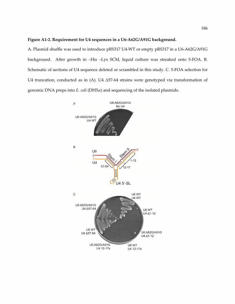
186
Figure A1‐2. Requirement for U4 sequences in a U6‐A62G/A91G background.
A. Plasmid shuffle was used to introduce pRS317 U4‐WT or empty pRS317 in a U6‐A62G/A91G
background. After growth in –His –Lys SCM, liquid culture was streaked onto 5‐FOA. B.
Schematic of sections of U4 sequence deleted or scrambled in this study. C. 5‐FOA selection for
U4 truncation, conducted as in (A). U4 Δ57‐64 strains were genotyped via transformation of
genomic DNA preps into E. coli (DH5α) and sequencing of the isolated plasmids.
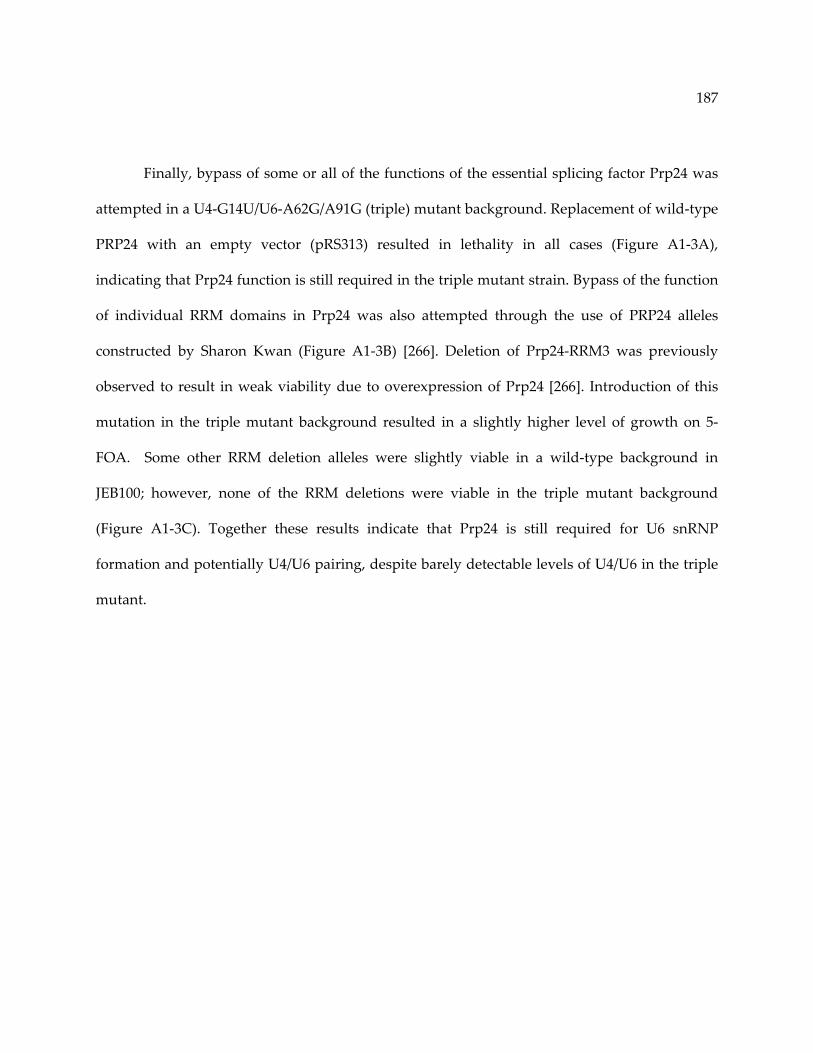
187
Finally, bypass of some or all of the functions of the essential splicing factor Prp24 was
attempted in a U4‐G14U/U6‐A62G/A91G (triple) mutant background. Replacement of wild‐type
PRP24 with an empty vector (pRS313) resulted in lethality in all cases (Figure A1‐3A),
indicating that Prp24 function is still required in the triple mutant strain. Bypass of the function
of individual RRM domains in Prp24 was also attempted through the use of PRP24 alleles
constructed by Sharon Kwan (Figure A1‐3B) [266]. Deletion of Prp24‐RRM3 was previously
observed to result in weak viability due to overexpression of Prp24 [266]. Introduction of this
mutation in the triple mutant background resulted in a slightly higher level of growth on 5‐
FOA. Some other RRM deletion alleles were slightly viable in a wild‐type background in
JEB100; however, none of the RRM deletions were viable in the triple mutant background
(Figure A1‐3C). Together these results indicate that Prp24 is still required for U6 snRNP
formation and potentially U4/U6 pairing, despite barely detectable levels of U4/U6 in the triple
mutant.
188
Figure A1‐3. Prp24 function is not bypassed in the triple mutant.
A. Plasmid shuffle was used to introduce pRS313 PRP24‐WT or empty pRS313 in a U6‐
A62G/A91G, U4‐G14U (Trp) background. After growth in –His –Lys ‐Trp SCM, liquid culture
was spotted in 10‐fold serial dilution on 5‐FOA. B. PRP24 RRM deletion constructs used in this
study, constructed by Sharon Kwan [266]. C. Serial dilutions (as in A) of RRM deletion construct
in a wild‐type or triple mutant background.

189
Appendix II: Alternate U2/U6 constructs and secondary structures
Overview:
En route to finding the ideal construct for analyzing the structure of U2/U6, I explored
some variations on truncations of the U2/U6 complex. Initially, we hoped to use traditional
NMR methods to solve the structure of U2/U6; however, it soon became clear that the best
approach was to use all of the sequence that contributes to base‐pairing. Two of the constructs
(JEH1 and JEH2) presented here completely lack Helix II (Figure A2‐1B and Figure A2‐2B), as
this portion of U2/U6 is not as highly conserved and is not essential in yeast [252]. The third
construct (JEH4, Figure A2‐3B) is similar to the 111 nt RNA presented in Chapter 3 but is
truncated such that Helix III consists of only four base‐pairs.
The secondary structures of these RNAs were consistent with the predicted structures.
JEH1 and JEH2 form the U6 ISL and Helix Ia (Figure A2‐1A, B and Figure A2‐2). JEH2 also
forms Helix III (Figure A2‐3). Neither RNA exhibits stable U2/U6 Helix Ib formation. Splitting
of the imino 1H resonance for residue U6‐G63 is observed in JEH1, potentially due to
heterogeneity at the 3’ end (Figure A2‐1A). Addition of 2 mM Mg2+ resulted in significant
chemical shift perturbation in the imino 1H resonance of U6‐U70 and detection of an additional
NOE cross‐peak between U6‐U70 and U6‐G71, suggesting stabilization of the U6 ISL pentaloop
(Figure A2‐1B, C). JEH4 forms the same overall fold as the 111 nt RNA, with the only exception
of the missing base‐pairs on the end of Helix III (Figure A2‐3A and B).

190
Figure A2‐1. Structure and Mg2+ dependence of Helix I and the U6 ISL (JEH1).
A. 1H‐1H 2D NOESY of Helix I linked to the U6 ISL (JEH1) at pH 7.0, 10°C (buffered by only
RNA). Assignments within the U6 ISL are shown in blue and Helix I assignments in green.
Resonances from non‐native residues are indicated in black (TL=tetraloop). B. Secondary
structure of JEH1 as determined by NMR. Black lines indicate observed base‐pairs and gray
lines indicate pairs inferred based on chemical shift. Red lines indicate base‐pairs that appear
upon addition of Mg2+ (U6‐71G) or shift strongly in Mg2+ (U6‐70U). C. Comparison of JEH1
spectra with and without 2 mM MgCl2. Only the chemical shift of U6‐70U changes
significantly. An additional NOE cross‐peak appears between U6‐70U and U6‐71G (red arrows),
suggesting stabilization of the pentaloop.

191

192
Figure A2‐2. Structure of Helix I and III with the U6 ISL (JEH2).
A. 1H‐1H 2D NOESY of the JEH2 RNA. Chemical shift assignments are consistent with the 111
nt construct (Chapter 3). Lines and resonance assignments are labeled according to secondary
structure as in Figure A2‐1. B. Secondary structure based on NMR assignments. Color‐coded as
above.

193
Figure A2‐3. Secondary structure of a 102 nt U2/U6 RNA (JEH4).
A. 1H‐1H 2D NOESY of the 102 nt construct (also JEH4 or DS8 short III). Chemical shift
assignments are consistent with the 111 nt construct (Chapter 3). Lines and resonance
assignments are labeled according to secondary structure as in Figure A2‐1. B. Secondary
structure based on NMR assignments. Color‐coded as above.

194
References
1. Djebali, S., C.A. Davis, A. Merkel, et al. (2012). Landscape of transcription in human cells. Nature. 489, 101‐8.
2. Hong, X., D.G. Scofield, and M. Lynch (2006). Intron size, abundance, and distribution within untranslated regions of genes. Mol Biol Evol. 23, 2392‐404.
3. Wahl, M.C., C.L. Will, and R. Luhrmann (2009). The spliceosome: design principles of a dynamic RNP machine. Cell. 136, 701‐18.
4. Reed, R. (2003). Coupling transcription, splicing and mRNA export. Curr Opin Cell Biol. 15, 326‐31.
5. Munoz, M.J., M. de la Mata, and A.R. Kornblihtt (2010). The carboxy terminal domain of RNA polymerase II and alternative splicing. Trends Biochem Sci. 35, 497‐504.
6. Yuryev, A., M. Patturajan, Y. Litingtung, et al. (1996). The C‐terminal domain of the largest subunit of RNA polymerase II interacts with a novel set of serine/arginine‐rich proteins. Proc Natl Acad Sci U S A. 93, 6975‐80.
7. Singh, J. and R.A. Padgett (2009). Rates of in situ transcription and splicing in large human genes. Nat Struct Mol Biol. 16, 1128‐33.
8. Brody, Y., N. Neufeld, N. Bieberstein, et al. (2011). The in vivo kinetics of RNA polymerase II elongation during co‐transcriptional splicing. PLoS Biol. 9, e1000573.
9. Nag, A. and J.A. Steitz (2012). Tri‐snRNP‐associated proteins interact with subunits of the TRAMP and nuclear exosome complexes, linking RNA decay and pre‐mRNA splicing. RNA biology. 9, 334‐42.
10. Houseley, J. and D. Tollervey (2009). The many pathways of RNA degradation. Cell. 136, 763‐76.
11. Mount, S.M. (1982). A catalogue of splice junction sequences. Nucleic Acids Res. 10, 459‐72.
12. Parker, R., P.G. Siliciano, and C. Guthrie (1987). Recognition of the TACTAAC box during mRNA splicing in yeast involves base pairing to the U2‐like snRNA. Cell. 49, 229‐39.
13. Rautmann, G. and R. Breathnach (1985). A role for branchpoints in splicing in vivo. Nature. 315, 430‐2.

195
14. Cellini, A., E. Felder, and J.J. Rossi (1986). Yeast pre‐messenger RNA splicing efficiency depends on critical spacing requirements between the branch point and 3ʹ splice site. EMBO J. 5, 1023‐30.
15. Brow, D.A. (2002). Allosteric cascade of spliceosome activation. Annu Rev Genet. 36, 333‐60.
16. Chapman, K.B. and J.D. Boeke (1991). Isolation and characterization of the gene encoding yeast debranching enzyme. Cell. 65, 483‐92.
17. Ruskin, B. and M.R. Green (1985). An RNA processing activity that debranches RNA lariats. Science. 229, 135‐40.
18. Hoskins, A.A., L.J. Friedman, S.S. Gallagher, et al. (2011). Ordered and dynamic assembly of single spliceosomes. Science. 331, 1289‐95.
19. Stevens, S.W., D.E. Ryan, H.Y. Ge, et al. (2002). Composition and functional characterization of the yeast spliceosomal penta‐snRNP. Mol Cell. 9, 31‐44.
20. Konarska, M.M. and P.A. Sharp (1988). Association of U2, U4, U5, and U6 small nuclear ribonucleoproteins in a spliceosome‐type complex in absence of precursor RNA. Proc Natl Acad Sci U S A. 85, 5459‐62.
21. Tseng, C.K. and S.C. Cheng (2008). Both catalytic steps of nuclear pre‐mRNA splicing are reversible. Science. 320, 1782‐4.
22. Cordin, O., D. Hahn, and J.D. Beggs (2012). Structure, function and regulation of spliceosomal RNA helicases. Curr Opin Cell Biol. 24, 431‐8.
23. Madhani, H.D. and C. Guthrie (1992). A novel base‐pairing interaction between U2 and U6 snRNAs suggests a mechanism for the catalytic activation of the spliceosome. Cell. 71, 803‐17.
24. Madhani, H.D., R. Bordonne, and C. Guthrie (1990). Multiple roles for U6 snRNA in the splicing pathway. Genes Dev. 4, 2264‐77.
25. Sun, J.S. and J.L. Manley (1995). A novel U2‐U6 snRNA structure is necessary for mammalian mRNA splicing. Genes Dev. 9, 843‐54.
26. Bringmann, P., B. Appel, J. Rinke, et al. (1984). Evidence for the existence of snRNAs U4 and U6 in a single ribonucleoprotein complex and for their association by intermolecular base pairing. EMBO J. 3, 1357‐63.
196
27. Hashimoto, C. and J.A. Steitz (1984). U4 and U6 RNAs coexist in a single small nuclear ribonucleoprotein particle. Nucleic Acids Res. 12, 3283‐93.
28. Butcher, S.E. and D.A. Brow (2005). Towards understanding the catalytic core structure of the spliceosome. Biochem Soc Trans. 33, 447‐9.
29. Santos, K.F., S.M. Jovin, G. Weber, et al. (2012). Structural basis for functional cooperation between tandem helicase cassettes in Brr2‐mediated remodeling of the spliceosome. Proc Natl Acad Sci U S A.
30. Zhang, L., J. Shen, M.T. Guarnieri, et al. (2007). Crystal structure of the C‐terminal domain of splicing factor Prp8 carrying retinitis pigmentosa mutants. Protein Sci. 16, 1024‐31.
31. Vithana, E.N., L. Abu‐Safieh, M.J. Allen, et al. (2001). A human homolog of yeast pre‐mRNA splicing gene, PRP31, underlies autosomal dominant retinitis pigmentosa on chromosome 19q13.4 (RP11). Mol Cell. 8, 375‐81.
32. Chakarova, C.F., M.M. Hims, H. Bolz, et al. (2002). Mutations in HPRP3, a third member of pre‐mRNA splicing factor genes, implicated in autosomal dominant retinitis pigmentosa. Hum Mol Genet. 11, 87‐92.
33. Coady, T.H. and C.L. Lorson (2011). SMN in spinal muscular atrophy and snRNP biogenesis. Wiley Interdiscip Rev RNA. 2, 546‐64.
34. Jia, Y., J.C. Mu, and S.L. Ackerman (2012). Mutation of a U2 snRNA gene causes global disruption of alternative splicing and neurodegeneration. Cell. 148, 296‐308.
35. Spitali, P. and A. Aartsma‐Rus (2012). Splice modulating therapies for human disease. Cell. 148, 1085‐8.
36. Bonnal, S., L. Vigevani, and J. Valcarcel (2012). The spliceosome as a target of novel antitumour drugs. Nat Rev Drug Discov. 11, 847‐59.
37. Brow, D.A. and C. Guthrie (1988). Spliceosomal RNA U6 is remarkably conserved from yeast to mammals. Nature. 334, 213‐8.
38. Kunkel, G.R., R.L. Maser, J.P. Calvet, and T. Pederson (1986). U6 small nuclear RNA is transcribed by RNA polymerase III. Proc Natl Acad Sci U S A. 83, 8575‐9.
39. Reddy, R., D. Henning, G. Das, et al. (1987). The capped U6 small nuclear RNA is transcribed by RNA polymerase III. J Biol Chem. 262, 75‐81.
197
40. Brow, D.A. and C. Guthrie (1990). Transcription of a yeast U6 snRNA gene requires a polymerase III promoter element in a novel position. Genes Dev. 4, 1345‐56.
41. Eschenlauer, J.B., M.W. Kaiser, V.L. Gerlach, and D.A. Brow (1993). Architecture of a yeast U6 RNA gene promoter. Mol Cell Biol. 13, 3015‐26.
42. Das, G., D. Henning, D. Wright, and R. Reddy (1988). Upstream regulatory elements are necessary and sufficient for transcription of a U6 RNA gene by RNA polymerase III. EMBO J. 7, 503‐12.
43. Galli, G., H. Hofstetter, and M.L. Birnstiel (1981). Two conserved sequence blocks within eukaryotic tRNA genes are major promoter elements. Nature. 294, 626‐31.
44. Kaiser, M.W. and D.A. Brow (1995). Lethal mutations in a yeast U6 RNA gene B block promoter element identify essential contacts with transcription factor‐IIIC. J Biol Chem. 270, 11398‐405.
45. Xue, D., D.A. Rubinson, B.K. Pannone, et al. (2000). U snRNP assembly in yeast involves the La protein. EMBO J. 19, 1650‐60.
46. Singh, R. and R. Reddy (1989). Gamma‐monomethyl phosphate: a cap structure in spliceosomal U6 small nuclear RNA. Proc Natl Acad Sci U S A. 86, 8280‐3.
47. Singh, R., S. Gupta, and R. Reddy (1990). Capping of mammalian U6 small nuclear RNA in vitro is directed by a conserved stem‐loop and AUAUAC sequence: conversion of a noncapped RNA into a capped RNA. Mol Cell Biol. 10, 939‐46.
48. Booth, B.L., Jr. and B.F. Pugh (1997). Identification and characterization of a nuclease specific for the 3ʹ end of the U6 small nuclear RNA. J Biol Chem. 272, 984‐91.
49. Trippe, R., E. Guschina, M. Hossbach, et al. (2006). Identification, cloning, and functional analysis of the human U6 snRNA‐specific terminal uridylyl transferase. RNA. 12, 1494‐504.
50. Shchepachev, V., H. Wischnewski, E. Missiaglia, et al. (2012). Mpn1, Mutated in Poikiloderma with Neutropenia Protein 1, Is a Conserved 3ʹ‐to‐5ʹ RNA Exonuclease Processing U6 Small Nuclear RNA. Cell Rep. 2, 855‐65.
51. Lund, E. and J.E. Dahlberg (1992). Cyclic 2ʹ,3ʹ‐phosphates and nontemplated nucleotides at the 3ʹ end of spliceosomal U6 small nuclear RNAʹs. Science. 255, 327‐30.
52. Mroczek, S., J. Krwawicz, J. Kutner, et al. (2012). C16orf57, a gene mutated in poikiloderma with neutropenia, encodes a putative phosphodiesterase responsible for the U6 snRNA 3ʹ end modification. Genes Dev. 26, 1911‐25.
198
53. Will, C.L. and R. Luhrmann (2001). Spliceosomal UsnRNP biogenesis, structure and function. Curr Opin Cell Biol. 13, 290‐301.
54. Tani, T. and Y. Ohshima (1991). mRNA‐type introns in U6 small nuclear RNA genes: implications for the catalysis in pre‐mRNA splicing. Genes Dev. 5, 1022‐31.
55. Brow, D.A. and C. Guthrie (1989). Splicing a spliceosomal RNA. Nature. 337, 14‐5.
56. Ryan, D.E., S.W. Stevens, and J. Abelson (2002). The 5ʹ and 3ʹ domains of yeast U6 snRNA: Lsm proteins facilitate binding of Prp24 protein to the U6 telestem region. RNA. 8, 1011‐33.
57. Karaduman, R., P. Dube, H. Stark, et al. (2008). Structure of yeast U6 snRNPs: arrangement of Prp24p and the LSm complex as revealed by electron microscopy. RNA. 14, 2528‐37.
58. Fortner, D.M., R.G. Troy, and D.A. Brow (1994). A stem/loop in U6 RNA defines a conformational switch required for pre‐mRNA splicing. Genes Dev. 8, 221‐33.
59. Huppler, A., L.J. Nikstad, A.M. Allmann, et al. (2002). Metal binding and base ionization in the U6 RNA intramolecular stem‐loop structure. Nat Struct Biol. 9, 431‐5.
60. Vidaver, R.M., D.M. Fortner, L.S. Loos‐Austin, and D.A. Brow (1999). Multiple functions of Saccharomyces cerevisiae splicing protein Prp24 in U6 RNA structural rearrangements. Genetics. 153, 1205‐18.
61. Venditti, V., L. Clos, 2nd, N. Niccolai, and S.E. Butcher (2009). Minimum‐energy path for a u6 RNA conformational change involving protonation, base‐pair rearrangement and base flipping. J Mol Biol. 391, 894‐905.
62. Yean, S.L., G. Wuenschell, J. Termini, and R.J. Lin (2000). Metal‐ion coordination by U6 small nuclear RNA contributes to catalysis in the spliceosome. Nature. 408, 881‐4.
63. McPheeters, D.S. (1996). Interactions of the yeast U6 RNA with the pre‐mRNA branch site. RNA. 2, 1110‐23.
64. Griffiths‐Jones, S., A. Bateman, M. Marshall, et al. (2003). Rfam: an RNA family database. Nucleic Acids Res. 31, 439‐41.
65. Bae, E., N.J. Reiter, C.A. Bingman, et al. (2007). Structure and interactions of the first three RNA recognition motifs of splicing factor prp24. J Mol Biol. 367, 1447‐58.
66. Bell, M., S. Schreiner, A. Damianov, et al. (2002). p110, a novel human U6 snRNP protein and U4/U6 snRNP recycling factor. EMBO J. 21, 2724‐35.
199
67. Martin‐Tumasz, S., N.J. Reiter, D.A. Brow, and S.E. Butcher (2010). Structure and functional implications of a complex containing a segment of U6 RNA bound by a domain of Prp24. RNA. 16, 792‐804.
68. Wassarman, D.A. and J.A. Steitz (1992). Interactions of small nuclear RNAʹs with precursor messenger RNA during in vitro splicing. Science. 257, 1918‐25.
69. Martin‐Tumasz, S., A.C. Richie, L.J. Clos, 2nd, et al. (2011). A novel occluded RNA recognition motif in Prp24 unwinds the U6 RNA internal stem loop. Nucleic Acids Res. 39, 7837‐47.
70. Achsel, T., H. Brahms, B. Kastner, et al. (1999). A doughnut‐shaped heteromer of human Sm‐like proteins binds to the 3ʹ‐end of U6 snRNA, thereby facilitating U4/U6 duplex formation in vitro. EMBO J. 18, 5789‐802.
71. Kambach, C., S. Walke, R. Young, et al. (1999). Crystal structures of two Sm protein complexes and their implications for the assembly of the spliceosomal snRNPs. Cell. 96, 375‐87.
72. Arning, S., P. Gruter, G. Bilbe, and A. Kramer (1996). Mammalian splicing factor SF1 is encoded by variant cDNAs and binds to RNA. RNA. 2, 794‐810.
73. Berglund, J.A., K. Chua, N. Abovich, et al. (1997). The splicing factor BBP interacts specifically with the pre‐mRNA branchpoint sequence UACUAAC. Cell. 89, 781‐7.
74. Zamore, P.D. and M.R. Green (1989). Identification, purification, and biochemical characterization of U2 small nuclear ribonucleoprotein auxiliary factor. Proc Natl Acad Sci U S A. 86, 9243‐7.
75. Rymond, B.C. and M. Rosbash (1985). Cleavage of 5ʹ splice site and lariat formation are independent of 3ʹ splice site in yeast mRNA splicing. Nature. 317, 735‐7.
76. Libri, D., N. Graziani, C. Saguez, and J. Boulay (2001). Multiple roles for the yeast SUB2/yUAP56 gene in splicing. Genes Dev. 15, 36‐41.
77. Perriman, R. and M. Ares, Jr. (2010). Invariant U2 snRNA nucleotides form a stem loop to recognize the intron early in splicing. Mol Cell. 38, 416‐27.
78. Brosi, R., K. Groning, S.E. Behrens, et al. (1993). Interaction of mammalian splicing factor SF3a with U2 snRNP and relation of its 60‐kD subunit to yeast PRP9. Science. 262, 102‐5.
79. Raghunathan, P.L. and C. Guthrie (1998). A spliceosomal recycling factor that reanneals U4 and U6 small nuclear ribonucleoprotein particles. Science. 279, 857‐60.
200
80. Rader, S.D. and C. Guthrie (2002). A conserved Lsm‐interaction motif in Prp24 required for efficient U4/U6 di‐snRNP formation. RNA. 8, 1378‐92.
81. Vidovic, I., S. Nottrott, K. Hartmuth, et al. (2000). Crystal structure of the spliceosomal 15.5kD protein bound to a U4 snRNA fragment. Mol Cell. 6, 1331‐42.
82. Falb, M., I. Amata, F. Gabel, et al. (2010). Structure of the K‐turn U4 RNA: a combined NMR and SANS study. Nucleic Acids Res. 38, 6274‐85.
83. Grainger, R.J. and J.D. Beggs (2005). Prp8 protein: at the heart of the spliceosome. RNA. 11, 533‐57.
84. Raghunathan, P.L. and C. Guthrie (1998). RNA unwinding in U4/U6 snRNPs requires ATP hydrolysis and the DEIH‐box splicing factor Brr2. Curr Biol. 8, 847‐55.
85. Mozaffari‐Jovin, S., K.F. Santos, H.H. Hsiao, et al. (2012). The Prp8 RNase H‐like domain inhibits Brr2‐mediated U4/U6 snRNA unwinding by blocking Brr2 loading onto the U4 snRNA. Genes Dev. 26, 2422‐34.
86. Hacker, I., B. Sander, M.M. Golas, et al. (2008). Localization of Prp8, Brr2, Snu114 and U4/U6 proteins in the yeast tri‐snRNP by electron microscopy. Nat Struct Mol Biol. 15, 1206‐12.
87. Wassarman, D.A. and J.A. Steitz (1993). A base‐pairing interaction between U2 and U6 small nuclear RNAs occurs in > 150S complexes in HeLa cell extracts: implications for the spliceosome assembly pathway. Proc Natl Acad Sci U S A. 90, 7139‐43.
88. Schneider, M., C.L. Will, M. Anokhina, et al. (2010). Exon definition complexes contain the tri‐snRNP and can be directly converted into B‐like precatalytic splicing complexes. Mol Cell. 38, 223‐35.
89. Xu, D. and J.D. Friesen (2001). Splicing factor slt11p and its involvement in formation of U2/U6 helix II in activation of the yeast spliceosome. Mol Cell Biol. 21, 1011‐23.
90. Fabrizio, P., J. Dannenberg, P. Dube, et al. (2009). The evolutionarily conserved core design of the catalytic activation step of the yeast spliceosome. Mol Cell. 36, 593‐608.
91. Hahn, D., G. Kudla, D. Tollervey, and J.D. Beggs (2012). Brr2p‐mediated conformational rearrangements in the spliceosome during activation and substrate repositioning. Genes Dev. 26, 2408‐21.
92. Maeder, C., A.K. Kutach, and C. Guthrie (2009). ATP‐dependent unwinding of U4/U6 snRNAs by the Brr2 helicase requires the C terminus of Prp8. Nat Struct Mol Biol. 16, 42‐8.

201
93. Chan, S.P., D.I. Kao, W.Y. Tsai, and S.C. Cheng (2003). The Prp19p‐associated complex in spliceosome activation. Science. 302, 279‐82.
94. Butcher, S.E. (2009). The spliceosome as ribozyme hypothesis takes a second step. Proc Natl Acad Sci U S A. 106, 12211‐2.
95. Burke, J.E., D.G. Sashital, X. Zuo, et al. (2012). Structure of the yeast U2/U6 snRNA complex. RNA. 18, 673‐83.
96. Sashital, D.G., G. Cornilescu, C.J. McManus, et al. (2004). U2‐U6 RNA folding reveals a group II intron‐like domain and a four‐helix junction. Nat Struct Mol Biol. 11, 1237‐42.
97. Mefford, M.A. and J.P. Staley (2009). Evidence that U2/U6 helix I promotes both catalytic steps of pre‐mRNA splicing and rearranges in between these steps. RNA. 15, 1386‐97.
98. Hilliker, A.K. and J.P. Staley (2004). Multiple functions for the invariant AGC triad of U6 snRNA. RNA. 10, 921‐8.
99. Sashital, D.G., V. Venditti, C.G. Angers, et al. (2007). Structure and thermodynamics of a conserved U2 snRNA domain from yeast and human. RNA. 13, 328‐38.
100. Cao, S. and S.J. Chen (2006). Free energy landscapes of RNA/RNA complexes: with applications to snRNA complexes in spliceosomes. J Mol Biol. 357, 292‐312.
101. Reiter, N.J., L.J. Nikstad, A.M. Allmann, et al. (2003). Structure of the U6 RNA intramolecular stem‐loop harboring an S(P)‐phosphorothioate modification. RNA. 9, 533‐42.
102. Sashital, D.G., A.M. Allmann, S.R. Van Doren, and S.E. Butcher (2003). Structural basis for a lethal mutation in U6 RNA. Biochemistry. 42, 1470‐7.
103. Gordon, P.M. and J.A. Piccirilli (2001). Metal ion coordination by the AGC triad in domain 5 contributes to group II intron catalysis. Nat Struct Biol. 8, 893‐8.
104. Lee, C., Y. Jaladat, A. Mohammadi, et al. (2010). Metal binding and substrate positioning by evolutionarily invariant U6 sequences in catalytically active protein‐free snRNAs. RNA. 16, 2226‐38.
105. Valadkhan, S., A. Mohammadi, Y. Jaladat, and S. Geisler (2009). Protein‐free small nuclear RNAs catalyze a two‐step splicing reaction. Proc Natl Acad Sci U S A. 106, 11901‐6.
106. Michel, F., M. Costa, and E. Westhof (2009). The ribozyme core of group II introns: a structure in want of partners. Trends Biochem Sci. 34, 189‐99.

202
107. Reyes, J.L., E.H. Gustafson, H.R. Luo, et al. (1999). The C‐terminal region of hPrp8 interacts with the conserved GU dinucleotide at the 5ʹ splice site. RNA. 5, 167‐79.
108. Pena, V., S. Liu, J.M. Bujnicki, et al. (2007). Structure of a multipartite protein‐protein interaction domain in splicing factor prp8 and its link to retinitis pigmentosa. Mol Cell. 25, 615‐24.
109. Yang, K., L. Zhang, T. Xu, et al. (2008). Crystal structure of the beta‐finger domain of Prp8 reveals analogy to ribosomal proteins. Proc Natl Acad Sci U S A. 105, 13817‐22.
110. Ritchie, D.B., M.J. Schellenberg, E.M. Gesner, et al. (2008). Structural elucidation of a PRP8 core domain from the heart of the spliceosome. Nat Struct Mol Biol. 15, 1199‐205.
111. Pena, V., A. Rozov, P. Fabrizio, et al. (2008). Structure and function of an RNase H domain at the heart of the spliceosome. EMBO J. 27, 2929‐40.
112. McGrail, J.C., A. Krause, and R.T. OʹKeefe (2009). The RNA binding protein Cwc2 interacts directly with the U6 snRNA to link the nineteen complex to the spliceosome during pre‐mRNA splicing. Nucleic Acids Res. 37, 4205‐17.
113. Schmitzova, J., N. Rasche, O. Dybkov, et al. (2012). Crystal structure of Cwc2 reveals a novel architecture of a multipartite RNA‐binding protein. EMBO J. 31, 2222‐34.
114. Madhani, H.D. and C. Guthrie (1994). Genetic interactions between the yeast RNA helicase homolog Prp16 and spliceosomal snRNAs identify candidate ligands for the Prp16 RNA‐dependent ATPase. Genetics. 137, 677‐87.
115. Koodathingal, P., T. Novak, J.A. Piccirilli, and J.P. Staley (2010). The DEAH box ATPases Prp16 and Prp43 cooperate to proofread 5ʹ splice site cleavage during pre‐mRNA splicing. Mol Cell. 39, 385‐95.
116. Liu, H.L. and S.C. Cheng (2012). The interaction of prp2 with a defined region of the intron is required for the first splicing reaction. Mol Cell Biol. 32, 5056‐66.
117. Tanaka, N. and B. Schwer (2005). Characterization of the NTPase, RNA‐binding, and RNA helicase activities of the DEAH‐box splicing factor Prp22. Biochemistry. 44, 9795‐803.
118. Ohi, M.D., A.J. Link, L. Ren, et al. (2002). Proteomics analysis reveals stable multiprotein complexes in both fission and budding yeasts containing Myb‐related Cdc5p/Cef1p, novel pre‐mRNA splicing factors, and snRNAs. Mol Cell Biol. 22, 2011‐24.
119. Tsai, R.T., R.H. Fu, F.L. Yeh, et al. (2005). Spliceosome disassembly catalyzed by Prp43 and its associated components Ntr1 and Ntr2. Genes Dev. 19, 2991‐3003.

203
120. Khalid, M.F., M.J. Damha, S. Shuman, and B. Schwer (2005). Structure‐function analysis of yeast RNA debranching enzyme (Dbr1), a manganese‐dependent phosphodiesterase. Nucleic Acids Res. 33, 6349‐60.
121. Nam, K., G. Lee, J. Trambley, et al. (1997). Severe growth defect in a Schizosaccharomyces pombe mutant defective in intron lariat degradation. Mol Cell Biol. 17, 809‐18.
122. Kudlinzki, D., A. Schmitt, H. Christian, and R. Ficner (2012). Structural analysis of the C‐terminal domain of the spliceosomal helicase Prp22. Biol Chem. 393, 1131‐40.
123. Walbott, H., S. Mouffok, R. Capeyrou, et al. (2010). Prp43p contains a processive helicase structural architecture with a specific regulatory domain. EMBO J. 29, 2194‐204.
124. He, Y., G.R. Andersen, and K.H. Nielsen (2010). Structural basis for the function of DEAH helicases. EMBO Rep. 11, 180‐6.
125. Small, E.C., S.R. Leggett, A.A. Winans, and J.P. Staley (2006). The EF‐G‐like GTPase Snu114p regulates spliceosome dynamics mediated by Brr2p, a DExD/H box ATPase. Mol Cell. 23, 389‐99.
126. Brenner, T.J. and C. Guthrie (2005). Genetic analysis reveals a role for the C terminus of the Saccharomyces cerevisiae GTPase Snu114 during spliceosome activation. Genetics. 170, 1063‐80.
127. Vaidya, V.C., V. Seshadri, and U. Vijayraghavan (1996). An extragenic suppressor of prp24‐1 defines genetic interaction between PRP24 and PRP21 gene products of Saccharomyces cerevisiae. Mol Gen Genet. 250, 267‐76.
128. Mnaimneh, S., A.P. Davierwala, J. Haynes, et al. (2004). Exploration of essential gene functions via titratable promoter alleles. Cell. 118, 31‐44.
129. Golas, M.M., B. Sander, S. Bessonov, et al. (2010). 3D cryo‐EM structure of an active step I spliceosome and localization of its catalytic core. Mol Cell. 40, 927‐38.
130. Samatov, T.R., A. Wolf, P. Odenwalder, et al. (2012). Psoromic acid derivatives: a new family of small‐molecule pre‐mRNA splicing inhibitors discovered by a stage‐specific high‐throughput in vitro splicing assay. Chembiochem. 13, 640‐4.
131. Roybal, G.A. and M.S. Jurica (2010). Spliceostatin A inhibits spliceosome assembly subsequent to prespliceosome formation. Nucleic Acids Res. 38, 6664‐72.
132. Alcid, E.A. and M.S. Jurica (2008). A protein‐based EM label for RNA identifies the location of exons in spliceosomes. Nat Struct Mol Biol. 15, 213‐5.

204
133. Nollmann, M., W.M. Stark, and O. Byron (2004). Low‐resolution reconstruction of a synthetic DNA holliday junction. Biophys J. 86, 3060‐9.
134. Chen, H., S.P. Meisburger, S.A. Pabit, et al. (2012). Ionic strength‐dependent persistence lengths of single‐stranded RNA and DNA. Proc Natl Acad Sci U S A. 109, 799‐804.
135. Roh, J.H., L. Guo, J.D. Kilburn, et al. (2010). Multistage collapse of a bacterial ribozyme observed by time‐resolved small‐angle X‐ray scattering. J Am Chem Soc. 132, 10148‐54.
136. Pollack, L. and S. Doniach (2009). Time‐resolved X‐ray scattering and RNA folding. Methods Enzymol. 469, 253‐68.
137. Russell, R., I.S. Millett, S. Doniach, and D. Herschlag (2000). Small angle X‐ray scattering reveals a compact intermediate in RNA folding. Nat Struct Biol. 7, 367‐70.
138. Lipfert, J., J. Ouellet, D.G. Norman, et al. (2008). The complete VS ribozyme in solution studied by small‐angle X‐ray scattering. Structure. 16, 1357‐67.
139. Kazantsev, A.V., R.P. Rambo, S. Karimpour, et al. (2011). Solution structure of RNase P RNA. RNA. 17, 1159‐71.
140. Grishaev, A., J. Ying, M.D. Canny, et al. (2008). Solution structure of tRNAVal from refinement of homology model against residual dipolar coupling and SAXS data. J Biomol NMR. 42, 99‐109.
141. Zuo, X., J. Wang, P. Yu, et al. (2010). Solution structure of the cap‐independent translational enhancer and ribosome‐binding element in the 3ʹ UTR of turnip crinkle virus. Proc Natl Acad Sci U S A. 107, 1385‐90.
142. Hammond, J.A., R.P. Rambo, M.E. Filbin, and J.S. Kieft (2009). Comparison and functional implications of the 3D architectures of viral tRNA‐like structures. RNA. 15, 294‐307.
143. Ali, M., J. Lipfert, S. Seifert, et al. (2010). The ligand‐free state of the TPP riboswitch: a partially folded RNA structure. J Mol Biol. 396, 153‐65.
144. Chen, B., X. Zuo, Y.X. Wang, and T.K. Dayie (2012). Multiple conformations of SAM‐II riboswitch detected with SAXS and NMR spectroscopy. Nucleic Acids Res. 40, 3117‐30.
145. Baird, N.J. and A.R. Ferre‐DʹAmare (2010). Idiosyncratically tuned switching behavior of riboswitch aptamer domains revealed by comparative small‐angle X‐ray scattering analysis. RNA. 16, 598‐609.

205
146. Lipfert, J., R. Das, V.B. Chu, et al. (2007). Structural transitions and thermodynamics of a glycine‐dependent riboswitch from Vibrio cholerae. J Mol Biol. 365, 1393‐406.
147. Garst, A.D., A. Heroux, R.P. Rambo, and R.T. Batey (2008). Crystal structure of the lysine riboswitch regulatory mRNA element. J Biol Chem. 283, 22347‐51.
148. Pollack, L. (2011). Time resolved SAXS and RNA folding. Biopolymers. 95, 543‐9.
149. Bernado, P., E. Mylonas, M.V. Petoukhov, et al. (2007). Structural characterization of flexible proteins using small‐angle X‐ray scattering. J Am Chem Soc. 129, 5656‐64.
150. Pelikan, M., G.L. Hura, and M. Hammel (2009). Structure and flexibility within proteins as identified through small angle X‐ray scattering. Gen Physiol Biophys. 28, 174‐89.
151. Wang, Y.X., X. Zuo, J. Wang, et al. (2010). Rapid global structure determination of large RNA and RNA complexes using NMR and small‐angle X‐ray scattering. Methods. 52, 180‐91.
152. Rambo, R.P. and J.A. Tainer (2010). Improving small‐angle X‐ray scattering data for structural analyses of the RNA world. RNA. 16, 638‐46.
153. Jachimska, B., M. Wasilewska, and Z. Adamczyk (2008). Characterization of globular protein solutions by dynamic light scattering, electrophoretic mobility, and viscosity measurements. Langmuir. 24, 6866‐72.
154. Ferré DʹAmaré, A.R., Burley, Stephen, K. (1997). Dynamic light‐scattering as a tool for evaluating crystallizability of macromolecules. Methods Enzymol. 276, 157‐166.
155. Hennig, M., J.R. Williamson, A.S. Brodsky, and J.L. Battiste (2001). Recent advances in RNA structure determination by NMR. Curr Protoc Nucleic Acid Chem. Chapter 7, Unit 7 7.
156. Milligan, J.F. and O.C. Uhlenbeck (1989). Synthesis of small RNAs using T7 RNA polymerase. Methods Enzymol. 180, 51‐62.
157. Nelissen, F.H., E.H. Leunissen, L. van de Laar, et al. (2012). Fast production of homogeneous recombinant RNA‐‐towards large‐scale production of RNA. Nucleic Acids Res. 40, e102.
158. Cavaluzzi, M.J. and P.N. Borer (2004). Revised UV extinction coefficients for nucleoside‐5ʹ‐monophosphates and unpaired DNA and RNA. Nucleic Acids Res. 32, e13.
159. Soliman, M., B.J. Jungnickel, and E. Meister (1998). Stable desmearing of slit‐collimated SAXS patterns by adequate numerical conditioning. Acta Crystallogr A. 54, 675‐681.
206
160. Svergun, D.I. (1992). Determination of the Regularization Parameter in Indirect‐Transform Methods Using Perceptual Criteria. J Appl Crystallogr. 25, 495‐503.
161. Zuker, M. (2003). Mfold web server for nucleic acid folding and hybridization prediction. Nucleic Acids Res. 31, 3406‐15.
162. Parisien, M. and F. Major (2008). The MC‐Fold and MC‐Sym pipeline infers RNA structure from sequence data. Nature. 452, 51‐5.
163. Harmanci, A.O., G. Sharma, and D.H. Mathews (2011). TurboFold: iterative probabilistic estimation of secondary structures for multiple RNA sequences. BMC bioinformatics. 12, 108.
164. Mathews, D.H., M.D. Disney, J.L. Childs, et al. (2004). Incorporating chemical modification constraints into a dynamic programming algorithm for prediction of RNA secondary structure. Proc Natl Acad Sci U S A. 101, 7287‐92.
165. Low, J.T. and K.M. Weeks (2010). SHAPE‐directed RNA secondary structure prediction. Methods. 52, 150‐8.
166. Juan, V. and C. Wilson (1999). RNA secondary structure prediction based on free energy and phylogenetic analysis. J Mol Biol. 289, 935‐47.
167. Lescoute, A. and E. Westhof (2006). Topology of three‐way junctions in folded RNAs. RNA. 12, 83‐93.
168. Fang, X., K. Littrell, X.J. Yang, et al. (2000). Mg2+‐dependent compaction and folding of yeast tRNAPhe and the catalytic domain of the B. subtilis RNase P RNA determined by small‐angle X‐ray scattering. Biochemistry. 39, 11107‐13.
169. Scott, L.G. and M. Hennig (2008). RNA structure determination by NMR. Methods Mol Biol. 452, 29‐61.
170. Sambrook, J. and D.W. Russell, Molecular cloning : a laboratory manual. 3rd ed. 2001, Cold Spring Harbor, N.Y.: Cold Spring Harbor Laboratory Press.
171. Pereira, M.J., V. Behera, and N.G. Walter (2010). Nondenaturing purification of co‐transcriptionally folded RNA avoids common folding heterogeneity. PLoS One. 5, e12953.
172. Huang, T.C., H. Toraya, T.N. Blanton, and Y. Wu (1993). X‐Ray‐Powder Diffraction Analysis of Silver Behenate, a Possible Low‐Angle Diffraction Standard. J Appl Crystallogr. 26, 180‐184.
207
173. Zhang, F., J. Ilavsky, G.G. Long, et al. (2010). Glassy Carbon as an Absolute Intensity Calibration Standard for Small‐Angle Scattering. Metall Mater Trans A. 41A, 1151‐1158.
174. Voets, I.K., W.A. Cruz, C. Moitzi, et al. (2010). DMSO‐induced denaturation of hen egg white lysozyme. J Phys Chem B. 114, 11875‐83.
175. Kozak, M. (2005). Glucose isomerase from Streptomyces rubiginosus ‐ potential molecular weight standard for small‐angle X‐ray scattering. J Appl Crystallogr. 38, 555‐558.
176. Zuo, X., J. Wang, T.R. Foster, et al. (2008). Global molecular structure and interfaces: refining an RNA:RNA complex structure using solution X‐ray scattering data. J Am Chem Soc. 130, 3292‐3.
177. Konarev, P.V., V.V. Volkov, A.V. Sokolova, et al. (2003). PRIMUS: a Windows PC‐based system for small‐angle scattering data analysis. J Appl Crystallogr. 36, 1277‐1282.
178. Svergun, D.I. (1999). Restoring low resolution structure of biological macromolecules from solution scattering using simulated annealing. Biophys J. 76, 2879‐86.
179. Franke, D. and D.I. Svergun (2009). DAMMIF, a program for rapid ab‐initio shape determination in small‐angle scattering. J Appl Crystallogr. 42, 342‐346.
180. Shpungin, I.L., V.A. Perevozchikov, I.N. Serdiuk, and G. Zaccai (1980). [Isolation and physical study of the 13S fragment of 16S RNA and its complex with ribosomal protein S4]. Mol Biol (Mosk). 14, 939‐50.
181. Kozin, M.B. and D.I. Svergun (2001). Automated matching of high‐ and low‐resolution structural models. J Appl Crystallogr. 34, 33‐41.
182. Engelman, D.M., P.B. Moore, and B.P. Schoenborn (1975). Neutron scattering measurements of separation and shape of proteins in 30S ribosomal subunit of Escherichia coli: S2‐S5, S5‐S8, S3‐S7. Proc Natl Acad Sci U S A. 72, 3888‐92.
183. Lake, J.A. (1967). Yeast transfer RNA: a small‐angle x‐ray study. Science. 156, 1371‐3.
184. Ninio, J., V. Luzzati, and M. Yaniv (1972). Comparative small‐angle x‐ray scattering studies on unacylated, acylated and cross‐linked Escherichia coli transfer RNA I Val. J Mol Biol. 71, 217‐29.
185. Svergun, D.I., N. Burkhardt, J.S. Pedersen, et al. (1997). Solution scattering structural analysis of the 70 S Escherichia coli ribosome by contrast variation. II. A model of the ribosome and its RNA at 3.5 nm resolution. J Mol Biol. 271, 602‐18.
208
186. Das, R., L.W. Kwok, I.S. Millett, et al. (2003). The fastest global events in RNA folding: electrostatic relaxation and tertiary collapse of the Tetrahymena ribozyme. J Mol Biol. 332, 311‐9.
187. Lipfert, J., A.Y. Sim, D. Herschlag, and S. Doniach (2010). Dissecting electrostatic screening, specific ion binding, and ligand binding in an energetic model for glycine riboswitch folding. RNA. 16, 708‐19.
188. Claridge, J.K., S.J. Headey, J.Y. Chow, et al. (2009). A picornaviral loop‐to‐loop replication complex. J Struct Biol. 166, 251‐62.
189. Stark, H. and R. Luhrmann (2006). Cryo‐electron microscopy of spliceosomal components. Annu Rev Biophys Biomol Struct. 35, 435‐57.
190. Miyazaki, Y., R.N. Irobalieva, B.S. Tolbert, et al. (2010). Structure of a conserved retroviral RNA packaging element by NMR spectroscopy and cryo‐electron tomography. J Mol Biol. 404, 751‐72.
191. Jonikas, M.A., R.J. Radmer, A. Laederach, et al. (2009). Coarse‐grained modeling of large RNA molecules with knowledge‐based potentials and structural filters. RNA. 15, 189‐99.
192. Xia, Z., D.P. Gardner, R.R. Gutell, and P. Ren (2010). Coarse‐grained model for simulation of RNA three‐dimensional structures. J Phys Chem B. 114, 13497‐506.
193. Suhre, K. and Y.H. Sanejouand (2004). ElNemo: a normal mode web server for protein movement analysis and the generation of templates for molecular replacement. Nucleic Acids Res. 32, W610‐4.
194. Yang, S., M. Parisien, F. Major, and B. Roux (2010). RNA structure determination using SAXS data. J Phys Chem B. 114, 10039‐48.
195. Schneidman‐Duhovny, D., M. Hammel, and A. Sali (2010). FoXS: a web server for rapid computation and fitting of SAXS profiles. Nucleic Acids Res. 38, W540‐4.
196. Price, S.R., N. Ito, C. Oubridge, et al. (1995). Crystallization of RNA‐protein complexes. I. Methods for the large‐scale preparation of RNA suitable for crystallographic studies. J Mol Biol. 249, 398‐408.
197. Walker, S.C., J.M. Avis, and G.L. Conn (2003). General plasmids for producing RNA in vitro transcripts with homogeneous ends. Nucleic Acids Res. 31, e82.
198. Valadkhan, S. (2010). Role of the snRNAs in spliceosomal active site. RNA biology. 7, 345‐53.

209
199. Padgett, R.A., M.M. Konarska, P.J. Grabowski, et al. (1984). Lariat RNAʹs as intermediates and products in the splicing of messenger RNA precursors. Science. 225, 898‐903.
200. Egecioglu, D.E. and G. Chanfreau (2011). Proofreading and spellchecking: a two‐tier strategy for pre‐mRNA splicing quality control. RNA. 17, 383‐9.
201. Luukkonen, B.G. and B. Seraphin (1998). Genetic interaction between U6 snRNA and the first intron nucleotide in Saccharomyces cerevisiae. RNA. 4, 167‐80.
202. Datta, B. and A.M. Weiner (1991). Genetic evidence for base pairing between U2 and U6 snRNA in mammalian mRNA splicing. Nature. 352, 821‐4.
203. Hausner, T.P., L.M. Giglio, and A.M. Weiner (1990). Evidence for base‐pairing between mammalian U2 and U6 small nuclear ribonucleoprotein particles. Genes Dev. 4, 2146‐56.
204. Collins, C.A. and C. Guthrie (2000). The question remains: is the spliceosome a ribozyme? Nat Struct Biol. 7, 850‐4.
205. Gordon, P.M., E.J. Sontheimer, and J.A. Piccirilli (2000). Metal ion catalysis during the exon‐ligation step of nuclear pre‐mRNA splicing: extending the parallels between the spliceosome and group II introns. RNA. 6, 199‐205.
206. Keating, K.S., N. Toor, P.S. Perlman, and A.M. Pyle (2010). A structural analysis of the group II intron active site and implications for the spliceosome. RNA. 16, 1‐9.
207. Valadkhan, S. and J.L. Manley (2003). Characterization of the catalytic activity of U2 and U6 snRNAs. RNA. 9, 892‐904.
208. Valadkhan, S. and J.L. Manley (2001). Splicing‐related catalysis by protein‐free snRNAs. Nature. 413, 701‐7.
209. Valadkhan, S., A. Mohammadi, C. Wachtel, and J.L. Manley (2007). Protein‐free spliceosomal snRNAs catalyze a reaction that resembles the first step of splicing. RNA. 13, 2300‐11.
210. Yu, Y.T., P.A. Maroney, E. Darzynkiwicz, and T.W. Nilsen (1995). U6 snRNA function in nuclear pre‐mRNA splicing: a phosphorothioate interference analysis of the U6 phosphate backbone. RNA. 1, 46‐54.
211. Steitz, T.A. and J.A. Steitz (1993). A general two‐metal‐ion mechanism for catalytic RNA. Proc Natl Acad Sci U S A. 90, 6498‐502.

210
212. Toor, N., K.S. Keating, S.D. Taylor, and A.M. Pyle (2008). Crystal structure of a self‐spliced group II intron. Science. 320, 77‐82.
213. Sontheimer, E.J., S. Sun, and J.A. Piccirilli (1997). Metal ion catalysis during splicing of premessenger RNA. Nature. 388, 801‐5.
214. Blad, H., N.J. Reiter, F. Abildgaard, et al. (2005). Dynamics and metal ion binding in the U6 RNA intramolecular stem‐loop as analyzed by NMR. J Mol Biol. 353, 540‐55.
215. Rhode, B.M., K. Hartmuth, E. Westhof, and R. Luhrmann (2006). Proximity of conserved U6 and U2 snRNA elements to the 5ʹ splice site region in activated spliceosomes. EMBO J. 25, 2475‐86.
216. Ryan, D.E., C.H. Kim, J.B. Murray, et al. (2004). New tertiary constraints between the RNA components of active yeast spliceosomes: a photo‐crosslinking study. RNA. 10, 1251‐65.
217. Valadkhan, S. and J.L. Manley (2000). A tertiary interaction detected in a human U2‐U6 snRNA complex assembled in vitro resembles a genetically proven interaction in yeast. RNA. 6, 206‐19.
218. Madhani, H.D. and C. Guthrie (1994). Randomization‐selection analysis of snRNAs in vivo: evidence for a tertiary interaction in the spliceosome. Genes Dev. 8, 1071‐86.
219. Guo, Z., K.S. Karunatilaka, and D. Rueda (2009). Single‐molecule analysis of protein‐free U2‐U6 snRNAs. Nat Struct Mol Biol. 16, 1154‐9.
220. Li, C.F., M. Costa, and F. Michel (2011). Linking the branchpoint helix to a newly found receptor allows lariat formation by a group II intron. EMBO J. 30, 3040‐51.
221. Volkov, V.V.a.S., D.I. (2003). Uniqueness of ab‐initio shape determination in small‐angle scattering. J Appl Crystallogr. 36, 860‐864.
222. Wriggers, W. (2010). Using Situs for the integration of multi‐resolution structures. Biophys Rev. 2, 21‐27.
223. Gautheret, D., F. Major, and R. Cedergren (1993). Modeling the three‐dimensional structure of RNA using discrete nucleotide conformational sets. J Mol Biol. 229, 1049‐64.
224. Zweckstetter, M. and A. Bax (2000). Prediction of sterically induced alignment in a dilute liquid crystalline phase: Aid to protein structure determination by NMR. J Am Chem Soc. 122, 3791‐3792.

211
225. Friedrichs, M.S., P. Eastman, V. Vaidyanathan, et al. (2009). Accelerating molecular dynamic simulation on graphics processing units. J Comput Chem. 30, 864‐72.
226. Du, Z., J. Yu, N.B. Ulyanov, et al. (2004). Solution structure of a consensus stem‐loop D RNA domain that plays important roles in regulating translation and replication in enteroviruses and rhinoviruses. Biochemistry. 43, 11959‐72.
227. Theimer, C.A., L.D. Finger, L. Trantirek, and J. Feigon (2003). Mutations linked to dyskeratosis congenita cause changes in the structural equilibrium in telomerase RNA. Proc Natl Acad Sci U S A. 100, 449‐54.
228. Cornilescu, G., J.L. Marquardt, M. Ottiger, and A. Bax (1998). Validation of protein structure from anisotropic carbonyl chemical shifts in a dilute liquid crystalline phase. J Am Chem Soc. 120, 6836‐6837.
229. Wang, J., X. Zuo, P. Yu, et al. (2009). A method for helical RNA global structure determination in solution using small‐angle x‐ray scattering and NMR measurements. J Mol Biol. 393, 717‐34.
230. Xia, T., J. SantaLucia, Jr., M.E. Burkard, et al. (1998). Thermodynamic parameters for an expanded nearest‐neighbor model for formation of RNA duplexes with Watson‐Crick base pairs. Biochemistry. 37, 14719‐35.
231. Han, H. and P.B. Dervan (1994). Visualization of RNA tertiary structure by RNA‐EDTA.Fe(II) autocleavage: analysis of tRNA(Phe) with uridine‐EDTA.Fe(II) at position 47. Proc Natl Acad Sci U S A. 91, 4955‐9.
232. Smith, D.J., C.C. Query, and M.M. Konarska (2008). ʺNought may endure but mutabilityʺ: spliceosome dynamics and the regulation of splicing. Mol Cell. 30, 657‐66.
233. Konarska, M.M., J. Vilardell, and C.C. Query (2006). Repositioning of the reaction intermediate within the catalytic center of the spliceosome. Mol Cell. 21, 543‐53.
234. Vidal, V.P., L. Verdone, A.E. Mayes, and J.D. Beggs (1999). Characterization of U6 snRNA‐protein interactions. RNA. 5, 1470‐81.
235. Kandels‐Lewis, S. and B. Seraphin (1993). Involvement of U6 snRNA in 5ʹ splice site selection. Science. 262, 2035‐9.
236. Luukkonen, B.G. and B. Seraphin (1998). A role for U2/U6 helix Ib in 5ʹ splice site selection. RNA. 4, 915‐27.
237. McPheeters, D.S., P. Fabrizio, and J. Abelson (1989). In vitro reconstitution of functional yeast U2 snRNPs. Genes Dev. 3, 2124‐36.

212
238. Brunger, A.T., P.D. Adams, G.M. Clore, et al. (1998). Crystallography & NMR system: A new software suite for macromolecular structure determination. Acta Crystallogr D Biol Crystallogr. 54, 905‐21.
239. Schwieters, C.D., J.J. Kuszewski, N. Tjandra, and G.M. Clore (2003). The Xplor‐NIH NMR molecular structure determination package. J Magn Reson. 160, 65‐73.
240. Cheng, S.C. and J. Abelson (1987). Spliceosome assembly in yeast. Genes Dev. 1, 1014‐27.
241. Lamond, A.I., M.M. Konarska, P.J. Grabowski, and P.A. Sharp (1988). Spliceosome assembly involves the binding and release of U4 small nuclear ribonucleoprotein. Proc Natl Acad Sci U S A. 85, 411‐5.
242. Sawa, H. and J. Abelson (1992). Evidence for a base‐pairing interaction between U6 small nuclear RNA and 5ʹ splice site during the splicing reaction in yeast. Proc Natl Acad Sci U S A. 89, 11269‐73.
243. Lesser, C.F. and C. Guthrie (1993). Mutations in U6 snRNA that alter splice site specificity: implications for the active site. Science. 262, 1982‐8.
244. Brow, D.A. and R.M. Vidaver (1995). An element in human U6 RNA destabilizes the U4/U6 spliceosomal RNA complex. RNA. 1, 122‐31.
245. Shannon, K.W. and C. Guthrie (1991). Suppressors of a U4 snRNA mutation define a novel U6 snRNP protein with RNA‐binding motifs. Genes Dev. 5, 773‐85.
246. Kuhn, A.N. and D.A. Brow (2000). Suppressors of a cold‐sensitive mutation in yeast U4 RNA define five domains in the splicing factor Prp8 that influence spliceosome activation. Genetics. 155, 1667‐82.
247. Gietz, R.D., R.H. Schiestl, A.R. Willems, and R.A. Woods (1995). Studies on the transformation of intact yeast cells by the LiAc/SS‐DNA/PEG procedure. Yeast. 11, 355‐60.
248. McManus, C.J., M.L. Schwartz, S.E. Butcher, and D.A. Brow (2007). A dynamic bulge in the U6 RNA internal stem‐loop functions in spliceosome assembly and activation. RNA. 13, 2252‐65.
249. Kuhn, A.N., Z. Li, and D.A. Brow (1999). Splicing factor Prp8 governs U4/U6 RNA unwinding during activation of the spliceosome. Mol Cell. 3, 65‐75.
250. Umen, J.G. and C. Guthrie (1995). A novel role for a U5 snRNP protein in 3ʹ splice site selection. Genes Dev. 9, 855‐68.

213
251. Li, Z. and D.A. Brow (1993). A rapid assay for quantitative detection of specific RNAs. Nucleic Acids Res. 21, 4645‐6.
252. Field, D.J. and J.D. Friesen (1996). Functionally redundant interactions between U2 and U6 spliceosomal snRNAs. Genes Dev. 10, 489‐501.
253. Wu, J. and J.L. Manley (1992). Multiple functional domains of human U2 small nuclear RNA: strengthening conserved stem I can block splicing. Mol Cell Biol. 12, 5464‐73.
254. Jandrositz, A. and C. Guthrie (1995). Evidence for a Prp24 binding site in U6 snRNA and in a putative intermediate in the annealing of U6 and U4 snRNAs. EMBO J. 14, 820‐32.
255. Wilson, D.N. and J.H. Doudna Cate (2012). The structure and function of the eukaryotic ribosome. Cold Spring Harb Perspect Biol. 4.
256. Hilliker, A.K., M.A. Mefford, and J.P. Staley (2007). U2 toggles iteratively between the stem IIa and stem IIc conformations to promote pre‐mRNA splicing. Genes Dev. 21, 821‐34.
257. Reiter, N.J., A. Osterman, A. Torres‐Larios, et al. (2010). Structure of a bacterial ribonuclease P holoenzyme in complex with tRNA. Nature. 468, 784‐9.
258. Zhang, Q., N.K. Kim, and J. Feigon (2011). Architecture of human telomerase RNA. Proc Natl Acad Sci U S A. 108, 20325‐32.
259. Kim, N.K., A. Murali, and V.J. DeRose (2004). A distance ruler for RNA using EPR and site‐directed spin labeling. Chem Biol. 11, 939‐48.
260. Peabody, D.S. (1993). The RNA binding site of bacteriophage MS2 coat protein. EMBO J. 12, 595‐600.
261. Granneman, S., G. Kudla, E. Petfalski, and D. Tollervey (2009). Identification of protein binding sites on U3 snoRNA and pre‐rRNA by UV cross‐linking and high‐throughput analysis of cDNAs. Proc Natl Acad Sci U S A. 106, 9613‐8.
262. Shuster, E.O. and C. Guthrie (1988). Two conserved domains of yeast U2 snRNA are separated by 945 nonessential nucleotides. Cell. 55, 41‐8.
263. Chen, C.H., D.I. Kao, S.P. Chan, et al. (2006). Functional links between the Prp19‐associated complex, U4/U6 biogenesis, and spliceosome recycling. RNA. 12, 765‐74.
264. Crawford, D.J., A.A. Hoskins, L.J. Friedman, et al. (2008). Visualizing the splicing of single pre‐mRNA molecules in whole cell extract. RNA. 14, 170‐9.

214
265. Li, Z. and D.A. Brow (1996). A spontaneous duplication in U6 spliceosomal RNA uncouples the early and late functions of the ACAGA element in vivo. RNA. 2, 879‐94.
266. Kwan, S.S. (2005). Protein‐mediated U6 RNA conformational changes in the yeast spliceosome. Ph.D. in Biomolecular Chemistry, The University of Wisconsin, Madison, WI.