
The CAD System and Its Integration into the Shipyard's · PDF fileThe CAD System and Its...
8
The CAD System and Its Integration into the Shipyard's Integral IT System M. Milanović, R. Benčić & E. Vitasović USCS d.o.o., Flaciusova 1, 52100 Pula, Croatia 1 INTRODUCTION The appropriate product definition represents at pre- sent one of the key factors for its successful produc- tion and exploitation. This is also true for shipbuild- ing, where the survival on the tough market is tightly connected with the ability to deliver ships of re- quired quality at an acceptable price, ability which can be obtained by increasing the productivity and by cutting down the overheads. The productivity and overhead issues are closely connected with the busi- ness processes involved in ship design and produc- tion (Fig. 1) (Riisberg & Siksne Pedersen 2004). Figure 1. Main phases in the shipbuilding process. One of the most obvious aspects regarding the business processes is their overlapping, so the con- current and collaborative engineering approach is very important for the appropriate organization of these processes. The main goal is to shorten the time needed for the design and production of the ship, al- together with obtaining a higher quality of the prod- uct and a cutting of the costs. One of the key factors in increasing the efficiency of the shipyard business process in these conditions is adopting the concept of Electronic Product Definition (EPD). EPD is based on the assumption that the product (ship) should be defined in an electronic form as de- tailed and correct as possible. It allows obtaining a more efficient coordination of many, often contra- dictory, requests arising during the definition of such a complex product as a ship. This concept enables also to easily investigate on various alternatives in the early phases of the design process, together with correcting all the eventually detected errors, in order to have the product defined as completely as possi- ble before going in production, and, if possible, even before starting to order the necessary material. A CAD system plays a vital role in the ship's de- sign phase: the definition of the ship's electronic 3D model is crucial for the successfulness of its produc- tion. The concept of EPD goes beyond the CAD sys- tem itself, because its realization includes the inte- gration of the 3D CAD model with other important design and business data, such as the product struc- ture, attributes, data from ERP system, etc. Through ABSTRACT: The appropriate product definition represents today one of the key factors for its successful pro- duction and exploitation. This is also true for shipbuilding, where the survival on the tough market is tightly connected with the ability to deliver ships of required quality at an acceptable price, and in the established de- livery terms. For the definition of a ship, it being a complex product, various IT systems are used, and the in- tegration of such systems becomes more and more important. This paper describes the in-house developed CAD system as a part of the integral IT system solution used in Uljanik Shipyard and the principles and methods used for the development of the interface between CAD and other IT systems, particularly in the area of material handling and production control. The mechanisms of communication between the systems, used Web technologies and development tools, mainly based on Oracle RDBMS platform, are described in details. Finally, some examples and experiences derived from the integra- tion of the CAD and other IT systems (PDM, ERP), as well as the guidelines for the further interface devel- opment are presented.
-
Upload
truongliem -
Category
Documents
-
view
226 -
download
3
Transcript of The CAD System and Its Integration into the Shipyard's · PDF fileThe CAD System and Its...
The CAD System and Its Integration into the Shipyard's Integral IT System
M. Milanović, R. Benčić & E. Vitasović USCS d.o.o., Flaciusova 1, 52100 Pula, Croatia
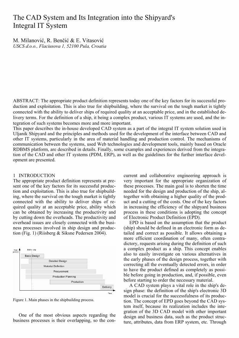
1 INTRODUCTION The appropriate product definition represents at pre-sent one of the key factors for its successful produc-tion and exploitation. This is also true for shipbuild-ing, where the survival on the tough market is tightly connected with the ability to deliver ships of re-quired quality at an acceptable price, ability which can be obtained by increasing the productivity and by cutting down the overheads. The productivity and overhead issues are closely connected with the busi-ness processes involved in ship design and produc-tion (Fig. 1) (Riisberg & Siksne Pedersen 2004).
Figure 1. Main phases in the shipbuilding process.
One of the most obvious aspects regarding the
business processes is their overlapping, so the con-
current and collaborative engineering approach is very important for the appropriate organization of these processes. The main goal is to shorten the time needed for the design and production of the ship, al-together with obtaining a higher quality of the prod-uct and a cutting of the costs. One of the key factors in increasing the efficiency of the shipyard business process in these conditions is adopting the concept of Electronic Product Definition (EPD).
EPD is based on the assumption that the product (ship) should be defined in an electronic form as de-tailed and correct as possible. It allows obtaining a more efficient coordination of many, often contra-dictory, requests arising during the definition of such a complex product as a ship. This concept enables also to easily investigate on various alternatives in the early phases of the design process, together with correcting all the eventually detected errors, in order to have the product defined as completely as possi-ble before going in production, and, if possible, even before starting to order the necessary material.
A CAD system plays a vital role in the ship's de-sign phase: the definition of the ship's electronic 3D model is crucial for the successfulness of its produc-tion. The concept of EPD goes beyond the CAD sys-tem itself, because its realization includes the inte-gration of the 3D CAD model with other important design and business data, such as the product struc-ture, attributes, data from ERP system, etc. Through
ABSTRACT: The appropriate product definition represents today one of the key factors for its successful pro-duction and exploitation. This is also true for shipbuilding, where the survival on the tough market is tightly connected with the ability to deliver ships of required quality at an acceptable price, and in the established de-livery terms. For the definition of a ship, it being a complex product, various IT systems are used, and the in-tegration of such systems becomes more and more important. This paper describes the in-house developed CAD system as a part of the integral IT system solution used in Uljanik Shipyard and the principles and methods used for the development of the interface between CAD and other IT systems, particularly in the area of material handling and production control. The mechanisms of communication between the systems, used Web technologies and development tools, mainly based on Oracle RDBMS platform, are described in details. Finally, some examples and experiences derived from the integra-tion of the CAD and other IT systems (PDM, ERP), as well as the guidelines for the further interface devel-opment are presented.
EPD all product data are integrated in one evolving product model which is available at the same time to different work groups from different departments.
2 THE CADDS/TRIDENT CAD SYSTEM
The Uljanik Shipyard has more than 30 years of ex-perience in using CAD systems. The development and implementation of the CAD system based on workstations, with characteristics and functionalities similar to today's systems, started in 1985. Since 1994 the development and implementation has been carried out by the USCS (Uljanik Shipbuilding Computer Systems), the shipyard's daughter com-pany formed from the former department for CAD systems, which started to implement the CAD sys-tem in the shipyard in the eighties.
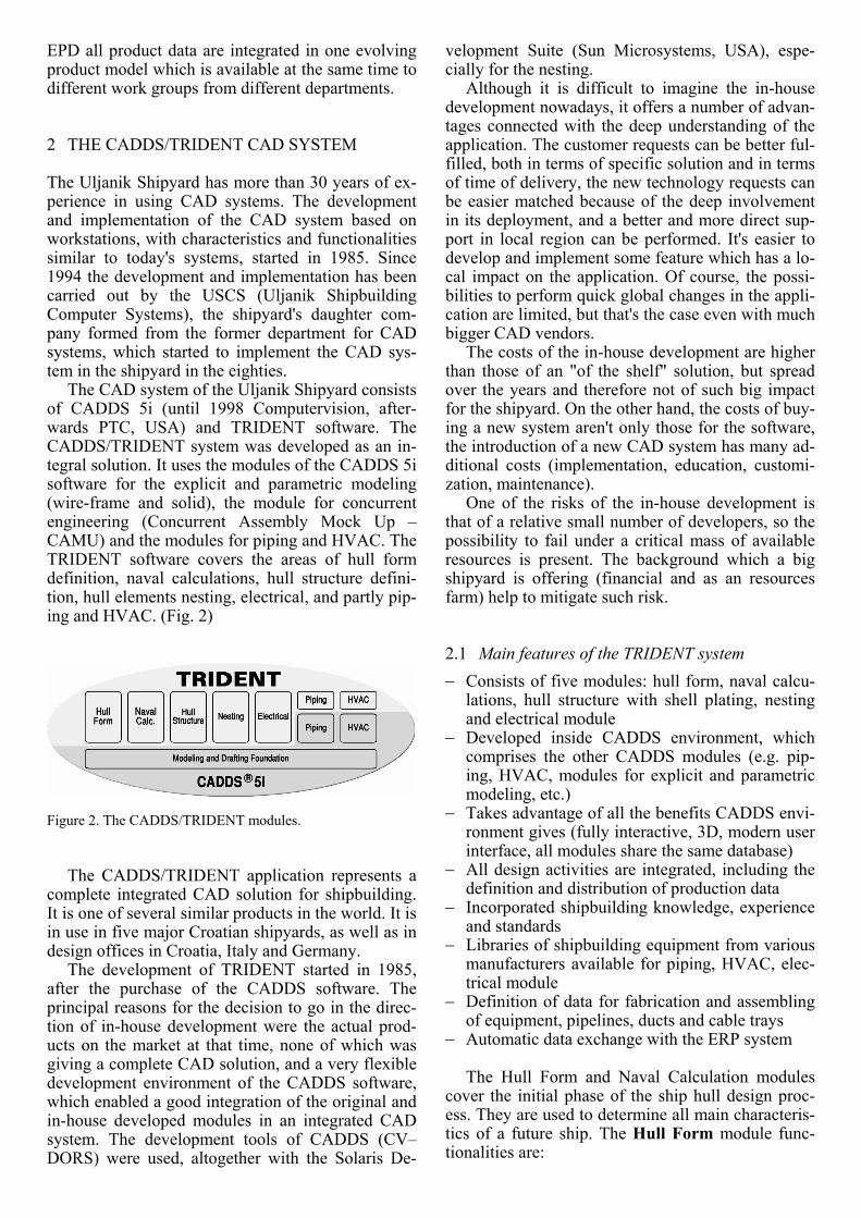
The CAD system of the Uljanik Shipyard consists of CADDS 5i (until 1998 Computervision, after-wards PTC, USA) and TRIDENT software. The CADDS/TRIDENT system was developed as an in-tegral solution. It uses the modules of the CADDS 5i software for the explicit and parametric modeling (wire-frame and solid), the module for concurrent engineering (Concurrent Assembly Mock Up – CAMU) and the modules for piping and HVAC. The TRIDENT software covers the areas of hull form definition, naval calculations, hull structure defini-tion, hull elements nesting, electrical, and partly pip-ing and HVAC. (Fig. 2)
Figure 2. The CADDS/TRIDENT modules.
The CADDS/TRIDENT application represents a
complete integrated CAD solution for shipbuilding. It is one of several similar products in the world. It is in use in five major Croatian shipyards, as well as in design offices in Croatia, Italy and Germany.
The development of TRIDENT started in 1985, after the purchase of the CADDS software. The principal reasons for the decision to go in the direc-tion of in-house development were the actual prod-ucts on the market at that time, none of which was giving a complete CAD solution, and a very flexible development environment of the CADDS software, which enabled a good integration of the original and in-house developed modules in an integrated CAD system. The development tools of CADDS (CV–DORS) were used, altogether with the Solaris De-
velopment Suite (Sun Microsystems, USA), espe-cially for the nesting.
Although it is difficult to imagine the in-house development nowadays, it offers a number of advan-tages connected with the deep understanding of the application. The customer requests can be better ful-filled, both in terms of specific solution and in terms of time of delivery, the new technology requests can be easier matched because of the deep involvement in its deployment, and a better and more direct sup-port in local region can be performed. It's easier to develop and implement some feature which has a lo-cal impact on the application. Of course, the possi-bilities to perform quick global changes in the appli-cation are limited, but that's the case even with much bigger CAD vendors.
The costs of the in-house development are higher than those of an "of the shelf" solution, but spread over the years and therefore not of such big impact for the shipyard. On the other hand, the costs of buy-ing a new system aren't only those for the software, the introduction of a new CAD system has many ad-ditional costs (implementation, education, customi-zation, maintenance).
One of the risks of the in-house development is that of a relative small number of developers, so the possibility to fail under a critical mass of available resources is present. The background which a big shipyard is offering (financial and as an resources farm) help to mitigate such risk.
2.1 Main features of the TRIDENT system − Consists of five modules: hull form, naval calcu-
lations, hull structure with shell plating, nesting and electrical module
− Developed inside CADDS environment, which comprises the other CADDS modules (e.g. pip-ing, HVAC, modules for explicit and parametric modeling, etc.)
− Takes advantage of all the benefits CADDS envi-ronment gives (fully interactive, 3D, modern user interface, all modules share the same database)
− All design activities are integrated, including the definition and distribution of production data
− Incorporated shipbuilding knowledge, experience and standards
− Libraries of shipbuilding equipment from various manufacturers available for piping, HVAC, elec-trical module
− Definition of data for fabrication and assembling of equipment, pipelines, ducts and cable trays
− Automatic data exchange with the ERP system The Hull Form and Naval Calculation modules
cover the initial phase of the ship hull design proc-ess. They are used to determine all main characteris-tics of a future ship. The Hull Form module func-tionalities are:
− Hull form modeling from a sketch or by variation from the archive of forms
− Tools for fairing curves and surfaces based on shipbuilding experience
− Transformation of existing hull forms to meet the required L, B, T, displacement or LCB
− Calculation of basic form properties (displace-ment, KM, VCB, LCB)
− Extended features for creation and modification of the hull form with NURBS curves
− Surface patches creation with NURBS curves mesh
− Automatic generation of building frames − Hull form details definition (e.g. mooring equip-
ment, rudder, etc.) The Naval Calculations module lets the design-
ers perform the necessary naval and geometrical cal-culations based on a hull created by the Hull Form module: − Naval calculations (hydrostatics, intact stability,
floodable length, launching, tonnage, Bon-Jean data)
− Geometric calculations for compartments (capac-ity, sounding and ullage tables, grainshifting moment)
− Damage stability − Loading conditions − Hydrostatic sections based 3D model generation
The Hull Structure module is used in the design
and detailed design phases of the ship design process to produce the necessary classification and work-shop documentation. It comprises:
− Definition of all hull structure elements such as
plates, profiles and brackets − Automated assembly definition with the appro-
priate weld assignment − Automated weld definition based according to
elements thickness and given standard weld type − Topological database (connection of structure
elements and holes, connection of profiles and cutouts, profiles and generating curves, etc.)
− Shipbuilding standards (cut-outs, holes, brackets, profile types, etc.)
− Non-graphical data handling (thickness, area, weight, material, quality, production data, etc.)
− Assembly and workshop drawings generation di-rectly from the 3D model
− Material specification (steel order definition for plates and profiles)
− Workshop data generation (profile assembly sur-plus and markings)
− Seams and butts definition − Shell plates definition (edges, marking curves,
frames, thickness, material, etc.) − Development of plates (calculation of minimal
rectangle area, weight, etc.)
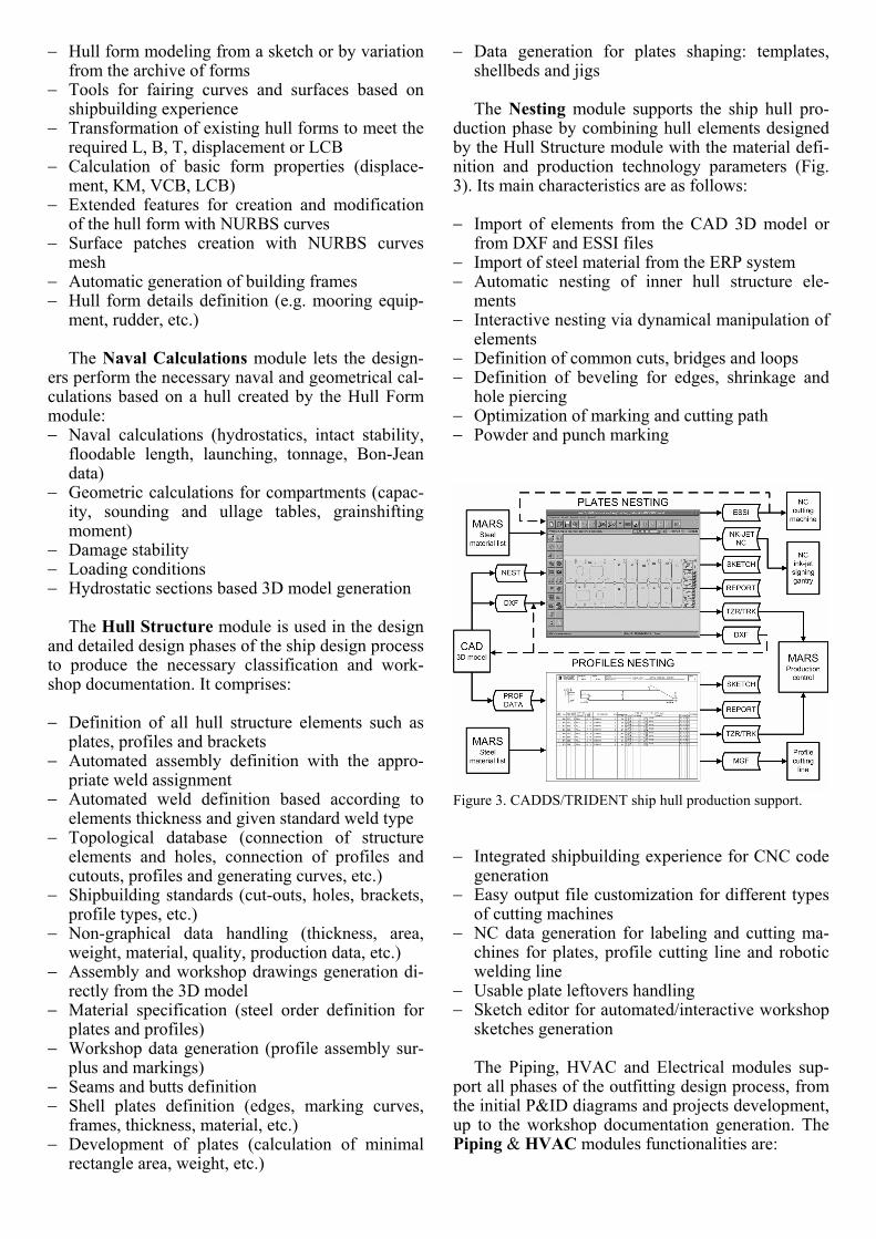
− Data generation for plates shaping: templates, shellbeds and jigs The Nesting module supports the ship hull pro-
duction phase by combining hull elements designed by the Hull Structure module with the material defi-nition and production technology parameters (Fig. 3). Its main characteristics are as follows:
− Import of elements from the CAD 3D model or
from DXF and ESSI files − Import of steel material from the ERP system − Automatic nesting of inner hull structure ele-
ments − Interactive nesting via dynamical manipulation of
elements − Definition of common cuts, bridges and loops − Definition of beveling for edges, shrinkage and
hole piercing − Optimization of marking and cutting path − Powder and punch marking
Figure 3. CADDS/TRIDENT ship hull production support.
− Integrated shipbuilding experience for CNC code generation
− Easy output file customization for different types of cutting machines
− NC data generation for labeling and cutting ma-chines for plates, profile cutting line and robotic welding line
− Usable plate leftovers handling − Sketch editor for automated/interactive workshop
sketches generation
The Piping, HVAC and Electrical modules sup-port all phases of the outfitting design process, from the initial P&ID diagrams and projects development, up to the workshop documentation generation. The Piping & HVAC modules functionalities are:
− Piping and Instrumentation Diagrams (P&ID) and respective BoM
− Catalogues of equipment and fittings for pipelines and ducts
− 3D modeling of piping and equipment for outfit-ting design (interactively with the Hull Structure module) using CAMU product structure
− Automatic generation of dimensional sketches (pipe spools) and respective BoM
− Generation of data for JEC PipeSpoolII for NC bending machine control
− Development of major HVAC systems, including flow calculation
− Duct spooling and workshop data generation The Electrical module covers all electrical as-
pects of ship design and production:
− Wiring diagrams generation − 3D modeling of electrical equipment − 3D modeling of cable trays − Automatic cable routing based on minimal cable
length method − Report generation based on cable book − Outdoor floodlight lighting calculation
Concerning the connections with other CAD sys-
tems by using standard formats, besides IGES and dxf, it is possible to export data in STEP format (AP 203 and AP 214 only). The data for hull structure elements can be exported in xml format as well.
Custom solutions, like the point to point data transfer of the complete hull structure (geometry, to-pology, attributes) from/to NauShip, a Microstation based shipbuilding CAD solution developed by NAUTICAD (Italy) was also developed.
Since the export/import of data through STEP AP's for shipbuilding (especially AP 215, AP 216 and AP 218) are features that CAD system have to provide nowadays, the development of such feature for the CADDS/TRIDENT is already planned.
The development of TRIDENT system in the last years has been determined by the technology re-newal of Croatian shipyards that started in the year 2000. The main improvements since then have been in the modules for hull structure definition and nest-ing. The modernization of the hull structure ele-ments cutting and assembling process (by introduc-ing plotters for plates labeling, new plates cutting machines, profile cutting line, micro panel line, etc.) originated the needs for more detailed production data definition and tighter connection between CADDS/TRIDENT system and the workshops. The automated generation of the workshop documenta-tion (sketches for nesting, pipe spools sketches, sketches for pipe supports) has been implemented, and the definition and transfer of data for NC/CNC cutting machines, robots and panel lines, and for pipe spools production workshop have been im-proved.
3 INTEGRATION WITH OTHER SYSTEMS
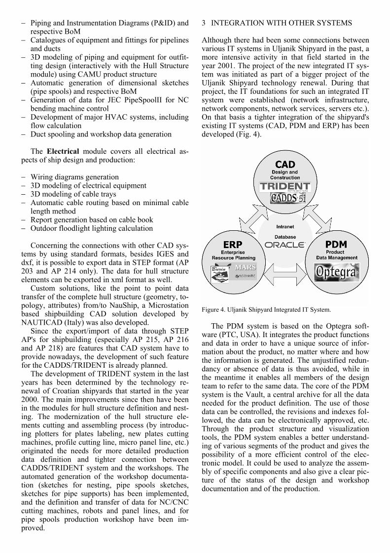
Although there had been some connections between various IT systems in Uljanik Shipyard in the past, a more intensive activity in that field started in the year 2001. The project of the new integrated IT sys-tem was initiated as part of a bigger project of the Uljanik Shipyard technology renewal. During that project, the IT foundations for such an integrated IT system were established (network infrastructure, network components, network services, servers etc.). On that basis a tighter integration of the shipyard's existing IT systems (CAD, PDM and ERP) has been developed (Fig. 4).
Figure 4. Uljanik Shipyard Integrated IT System.
The PDM system is based on the Optegra soft-
ware (PTC, USA). It integrates the product functions and data in order to have a unique source of infor-mation about the product, no matter where and how the information is generated. The unjustified redun-dancy or absence of data is thus avoided, while in the meantime it enables all members of the design team to refer to the same data. The core of the PDM system is the Vault, a central archive for all the data needed for the product definition. The use of those data can be controlled, the revisions and indexes fol-lowed, the data can be electronically approved, etc. Through the product structure and visualization tools, the PDM system enables a better understand-ing of various segments of the product and gives the possibility of a more efficient control of the elec-tronic model. It could be used to analyze the assem-bly of specific components and also give a clear pic-ture of the status of the design and workshop documentation and of the production.
The project of the Uljanik Shipyard technological renewal also defined the modernization of the exist-ing ERP system. That area has been covered with the Burin software, an application developed in-house through more than three decades. It was de-cided to redesign the Burin, basing it on new tech-nologies with the use of new development tools. In order to make a better use of the available resources for development, it was decided to cover the area of material definition and control with a new applica-tion, the MARS software (Logimatic, Denmark). That application, specially developed for the ship-building industry, covers the areas of project setup and budgeting control, material definition (steel and outfitting), purchase, stock, material handling (steel and outfitting) and production control.
Taking into account the fact that the product of the Uljanik Shipyard is defined completely in an electronic form, the interface between CADDS/ TRIDENT and MARS system proved to be an im-portant issue in the development of the shipyard's in-tegrated IT system. The interface between those two systems was the first ever developed worldwide.
3.1 CADDS/TRIDENT - MARS Interface Data Flow When defining the interface data flow (Fig. 5) and specifying the necessary procedures for the transfer of data between CADDS/TRIDENT and MARS sys-tems, the main intention was to ensure that the CADDS/TRIDENT system receives all the poten-tially useful data initially defined in MARS and vice versa, in a time and under authority defined by the shipyard's business rules. The automation of the whole process and the avoidance of any unnecessary manual data insertion was another project issue. There are two main areas covered by the interface: steel and outfitting (Lazarić et al. 2002).
Figure 5. Interface data sets for steel and outfitting.
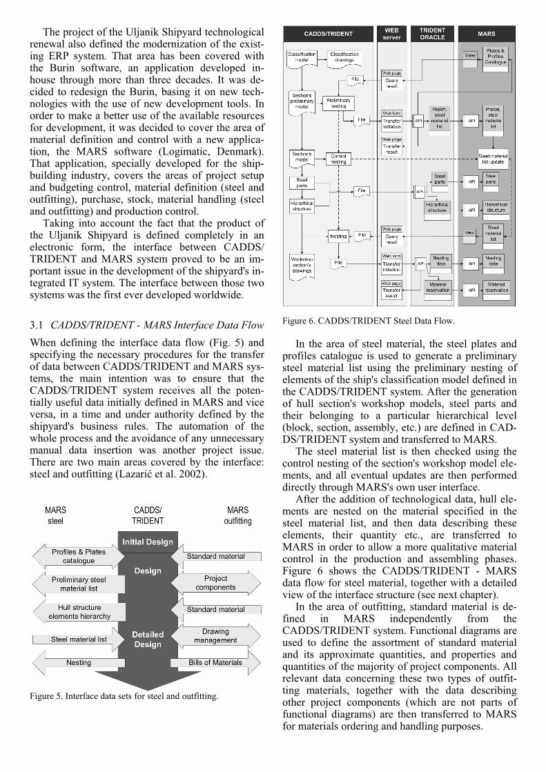
Figure 6. CADDS/TRIDENT Steel Data Flow.
In the area of steel material, the steel plates and
profiles catalogue is used to generate a preliminary steel material list using the preliminary nesting of elements of the ship's classification model defined in the CADDS/TRIDENT system. After the generation of hull section's workshop models, steel parts and their belonging to a particular hierarchical level (block, section, assembly, etc.) are defined in CAD-DS/TRIDENT system and transferred to MARS.
The steel material list is then checked using the control nesting of the section's workshop model ele-ments, and all eventual updates are then performed directly through MARS's own user interface.
After the addition of technological data, hull ele-ments are nested on the material specified in the steel material list, and then data describing these elements, their quantity etc., are transferred to MARS in order to allow a more qualitative material control in the production and assembling phases. Figure 6 shows the CADDS/TRIDENT - MARS data flow for steel material, together with a detailed view of the interface structure (see next chapter).
In the area of outfitting, standard material is de-fined in MARS independently from the CADDS/TRIDENT system. Functional diagrams are used to define the assortment of standard material and its approximate quantities, and properties and quantities of the majority of project components. All relevant data concerning these two types of outfit-ting materials, together with the data describing other project components (which are not parts of functional diagrams) are then transferred to MARS for materials ordering and handling purposes.
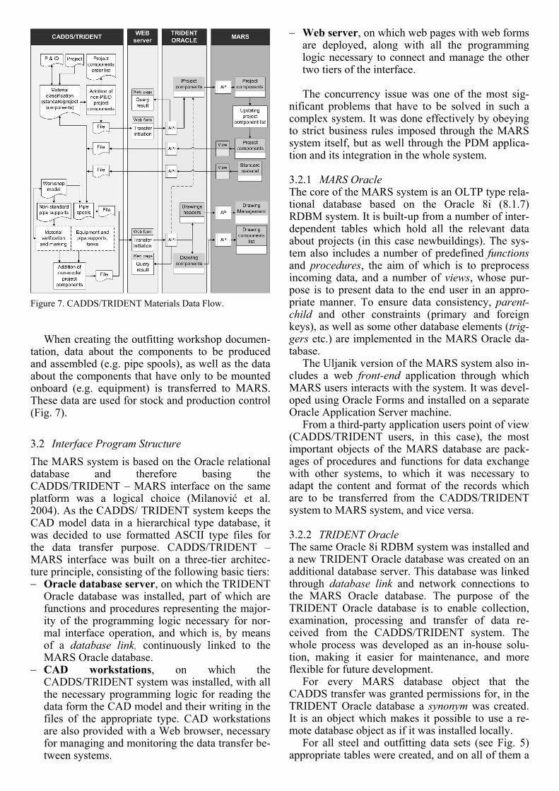
Figure 7. CADDS/TRIDENT Materials Data Flow.
When creating the outfitting workshop documen-
tation, data about the components to be produced and assembled (e.g. pipe spools), as well as the data about the components that have only to be mounted onboard (e.g. equipment) is transferred to MARS. These data are used for stock and production control (Fig. 7).
3.2 Interface Program Structure The MARS system is based on the Oracle relational database and therefore basing the CADDS/TRIDENT – MARS interface on the same platform was a logical choice (Milanović et al. 2004). As the CADDS/ TRIDENT system keeps the CAD model data in a hierarchical type database, it was decided to use formatted ASCII type files for the data transfer purpose. CADDS/TRIDENT – MARS interface was built on a three-tier architec-ture principle, consisting of the following basic tiers: − Oracle database server, on which the TRIDENT
Oracle database was installed, part of which are functions and procedures representing the major-ity of the programming logic necessary for nor-mal interface operation, and which is, by means of a database link, continuously linked to the MARS Oracle database.
− CAD workstations, on which the CADDS/TRIDENT system was installed, with all the necessary programming logic for reading the data form the CAD model and their writing in the files of the appropriate type. CAD workstations are also provided with a Web browser, necessary for managing and monitoring the data transfer be-tween systems.
− Web server, on which web pages with web forms are deployed, along with all the programming logic necessary to connect and manage the other two tiers of the interface. The concurrency issue was one of the most sig-
nificant problems that have to be solved in such a complex system. It was done effectively by obeying to strict business rules imposed through the MARS system itself, but as well through the PDM applica-tion and its integration in the whole system.
3.2.1 MARS Oracle The core of the MARS system is an OLTP type rela-tional database based on the Oracle 8i (8.1.7) RDBM system. It is built-up from a number of inter-dependent tables which hold all the relevant data about projects (in this case newbuildings). The sys-tem also includes a number of predefined functions and procedures, the aim of which is to preprocess incoming data, and a number of views, whose pur-pose is to present data to the end user in an appro-priate manner. To ensure data consistency, parent-child and other constraints (primary and foreign keys), as well as some other database elements (trig-gers etc.) are implemented in the MARS Oracle da-tabase.
The Uljanik version of the MARS system also in-cludes a web front-end application through which MARS users interacts with the system. It was devel-oped using Oracle Forms and installed on a separate Oracle Application Server machine.
From a third-party application users point of view (CADDS/TRIDENT users, in this case), the most important objects of the MARS database are pack-ages of procedures and functions for data exchange with other systems, to which it was necessary to adapt the content and format of the records which are to be transferred from the CADDS/TRIDENT system to MARS system, and vice versa.
3.2.2 TRIDENT Oracle The same Oracle 8i RDBM system was installed and a new TRIDENT Oracle database was created on an additional database server. This database was linked through database link and network connections to the MARS Oracle database. The purpose of the TRIDENT Oracle database is to enable collection, examination, processing and transfer of data re-ceived from the CADDS/TRIDENT system. The whole process was developed as an in-house solu-tion, making it easier for maintenance, and more flexible for future development.
For every MARS database object that the CADDS transfer was granted permissions for, in the TRIDENT Oracle database a synonym was created. It is an object which makes it possible to use a re-mote database object as if it was installed locally.
For all steel and outfitting data sets (see Fig. 5) appropriate tables were created, and on all of them a
trigger (an object the purpose of which is to activate a specified function automatically upon insertion, change or deletion of one table record) was placed. In this particular case, triggers are used to initiate the transfer of data records to the MARS system, ac-cording to the shipyard's policy of document ap-proval and management.
Some additional database objects are used for data transfer monitoring, user alerting and report generation, as well as for system state checking and administration. For example, all eventual transfer er-rors are stored in dedicated tables, from where they can be presented to interface users on demand, through Web interface (see chapter 3.2.4). Besides, administrators' messages can be accessed through restricted access Web interface, and the system also has the ability to send these messages through a standard SMTP (e-mail) server.
Most of the TRIDENT Oracle database objects are in-house solutions developed in PL/SQL pro-gramming language (Oracle procedural program-ming language based on standard set of SQL lan-guage commands) and Java (for the interaction between the database and the server's operating sys-tem). A detailed description of TRIDENT Oracle da-tabase is given in (Benčić & Todić 2003).
3.2.3 CADDS/TRIDENT System In the CADDS/TRIDENT system, all types of CAD model data (graphical and non-graphical) are stored in a hierarchical type database. − In CADDS/TRIDENT modules that deal with
hull structure modeling, dedicated TRIDENT instructions are developed for generating and formatting ASCII files that contain data for trans-fer. The case with the plates and profiles nesting module is very similar, and the difference con-sists only in the fact that here the necessary data are imported on one side from the CAD model, and from the other side, through the interface from MARS.
− Concerning outfitting, CVMAC macro language procedures are used for dealing with the CADDS/TRIDENT database, for importing the data coming through the interface, as well as for generating the output files for MARS.
In all these cases, procedures for generation of the transfer files are initiated by the CADDS/TRIDENT user when the document has been verified according to the shipyard document approval rules. Generated files are automatically being stored in the load folder of the TRIDENT Oracle database server.
An exception from this rule is the part of the in-terface that deals with the steel parts and hull struc-ture element hierarchy where, because of the inte-gration with the PDM system used for management of this part of documentation, the data transfer is be-ing initiated automatically, without the user's inter-vention, at the moment when the document has been approved.
3.2.4 Web integration A web server was installed as a mid-tier to connect CADDS/TRIDENT system with TRIDENT Oracle and MARS. The web server has two main roles: − To present data obtained from queries on views
defined in MARS and convert them to a format suitable for use in CADDS/TRIDENT system.
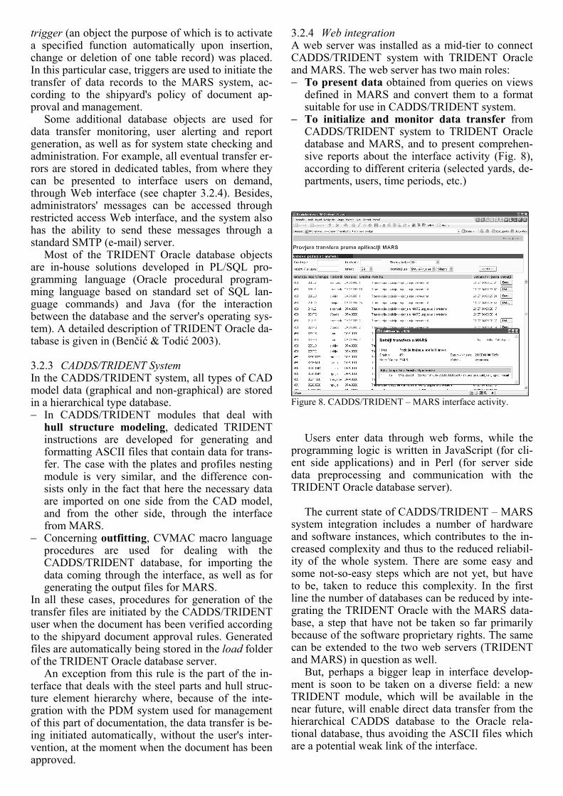
− To initialize and monitor data transfer from CADDS/TRIDENT system to TRIDENT Oracle database and MARS, and to present comprehen-sive reports about the interface activity (Fig. 8), according to different criteria (selected yards, de-partments, users, time periods, etc.)
Figure 8. CADDS/TRIDENT – MARS interface activity.
Users enter data through web forms, while the programming logic is written in JavaScript (for cli-ent side applications) and in Perl (for server side data preprocessing and communication with the TRIDENT Oracle database server).
The current state of CADDS/TRIDENT – MARS
system integration includes a number of hardware and software instances, which contributes to the in-creased complexity and thus to the reduced reliabil-ity of the whole system. There are some easy and some not-so-easy steps which are not yet, but have to be, taken to reduce this complexity. In the first line the number of databases can be reduced by inte-grating the TRIDENT Oracle with the MARS data-base, a step that have not be taken so far primarily because of the software proprietary rights. The same can be extended to the two web servers (TRIDENT and MARS) in question as well.
But, perhaps a bigger leap in interface develop-ment is soon to be taken on a diverse field: a new TRIDENT module, which will be available in the near future, will enable direct data transfer from the hierarchical CADDS database to the Oracle rela-tional database, thus avoiding the ASCII files which are a potential weak link of the interface.
4 CONCLUSION
In the definition of such a complex product, as a ship is, various IT systems are involved. The elec-tronic 3D model of the ship is a vital part of that definition and requires the right CAD solution for its generation. The electronic 3D model is the prerequi-site for an effective concurrent engineering and helps to coordinate various, often contradictory, re-quests which the designers of various ship systems have to fulfill. The benefit of using an electronic 3D model increase even more when a CAD system is in-terconnected with other IT systems used in the ship-yard, which all together contribute to the complete ship definition, production preparation and produc-tion. The integration of CAD system does not imply only the interface towards other IT systems, but also the connection and data generation for the produc-tion purposes (both for steel and outfitting).
In this paper, the in-house developed CAD sys-tem as a part of the integral IT system solution used in Uljanik Shipyard is described.
The principles and methods used for the devel-opment of the interface between CAD and other IT systems, particularly in the area of material handling and production control, were presented, together with the mechanisms of communication between the systems, used Web technologies and development tools.
Experiences from the daily use of the CADDS/TRIDENT system in the shipyard prove its advantages, but also give, as well as relevant exter-nal drivers (Whitfield et al. 2003), directions for fur-ther development. The CADDS/TRIDENT system development will be closely coupled with the mod-ernization of the steel parts production and assem-bling facilities. The new pipe workshop will be ap-propriately integrated, and it will be necessary to adapt the CAD system in order to obtain all possible benefits from such a modernization.
An important part of the CADDS/TRIDENT de-velopment is the project of the TRIDENT FEM modeler. The goal of the project, carried out in col-laboration with the Faculty of Mechanical Engineer-ing and Naval Architecture (Zagreb, Croatia), is to develop a tool for the definition of the ship structure FEM model on the basis of geometrical and topo-logical data taken directly from TRIDENT system.
The evolution of the Uljanik Shipyard integrated IT system will imply improvements in the CADDS/TRIDENT – MARS interface. The devel-opment is going towards automation and better data transfer control between the two systems.
The data transfer automation will depend on the PDM system range of use, especially in the outfit-ting, because it will enable to perform the data trans-fer driven by the approval of the documentation, which is controlled by the PDM system.
One of the new data sets included in the CADDS/TRIDENT – MARS interface will be the
status of completion of parts and assemblies. Those data will be transferred from MARS to the PDM system in order to have a better view of the produc-tion status through product structure and visualiza-tion tools.
All the mentioned improvements will lead to a more refined IT system, having a better coordination with the Uljanik Shipyard documentation generation procedures, production preparation and production. This will also contribute to the effectiveness of the overall shipbuilding process and, consequently, to the shipyard competitiveness.
REFERENCES
Alonso, F. et al. 2002. Collaborative Engineering in Shipbuild-ing, ICCAS 2002 Conference Proceedings, Malmö, Swe-den.
Benčić, R. & Todić, M. 2003. TRIDENT Oracle – Application Packages Description, USCS d.o.o., Pula.
Lazarić, M. et al., 2002. Interface CADDS5 – MARS, Specifi-cation, Uljanik shipyard, Pula.
Milanović, M. et al. 2004. Integration of CADDS/TRIDENT and MARS System, Sorta 2004 Symposium Proceedings, Plitvice Lakes, Croatia.
Riisberg, L. & Siksne Pedersen, I. 2004. IT Support of Inte-grated Processes in Modern Shipbuilding, Sorta 2004 Sym-posium Proceedings, Plitvice Lakes, Croatia.
Torp, K. et al. 2002. Integrating Logistic Systems in Shipbuild-ing, ICCAS 2002 Conference Proceedings, Malmö, Swe-den.
Whitfield, R.I. et al. 2003. Ship Product Modeling, Journal of Ship Production, Vol.19, No.4, November 2003, pp 230-245, SNAME, New Jersey.


