The BReAThe NIoV VeNTIlATIoN...
28
THE BREATHE NIOV TM VENTILATION SYSTEM PATIENT Instructions for Use Breathe Technologies, Inc. 175 Technology Drive, Suite 100 Irvine, CA 92618 USA 1-877-698-1325 [email protected] www.breathetechnologies.com Technical Support and Customer Service United States: 1-877-698-1326 www.BreatheNIOV.com PL-50-0037-E ©2012. NIOV is a trademark of Breathe Technologies, Inc.
Transcript of The BReAThe NIoV VeNTIlATIoN...

THE BREATHE NIOV TM VENT I LAT ION SYSTEM
PAT I E N T Instructions for Use
Breathe Technologies, Inc.175 Technology Drive, Suite 100 Irvine, CA 92618 USA
1-877-698-1325
[email protected] www.breathetechnologies.com
Technical Support and Customer ServiceUnited States: 1-877-698-1326
www.BreatheNIOV.com
PL-50-0037-E ©2012. NIOV is a trademark of Breathe Technologies, Inc.
iii
This manual provides detailed information about the Breathe Non-Invasive Open Ventilation (NIOV) System and step-by-step instructions for using its features.
Chapter 1: Introduction includes critical information that must be read before using the system:
Indications for Use outlines who can typically benefit from using the ventilation system.
Safety Information lists precautions that must be taken to ensure safe operation of the ventilation system.
Chapter 2: System Overview gives an overview of the ventilation system’s features.
Chapter 3: Using the Ventilation System describes the six basic tasks that you will perform when using the system:
• Checkthebatterycharge.
• Connectandturnonanoxygensupply.
• ConnectandweartheBreatheNIOVPillows Interface.
• Attachtheventilator.
• Turnontheventilatorandchooseanactivity setting.
• Adjustthetriggersensitivity.
Chapter 4: Alarms and Troubleshooting describes how alarms are displayed and gives information on what triggers them and how to clear them.
Chapter 5: Setup and Care describes procedures for defining ventilator system settings and for caring for the system.
Chapter 6: Icons provides a reference chart for the symbols used.
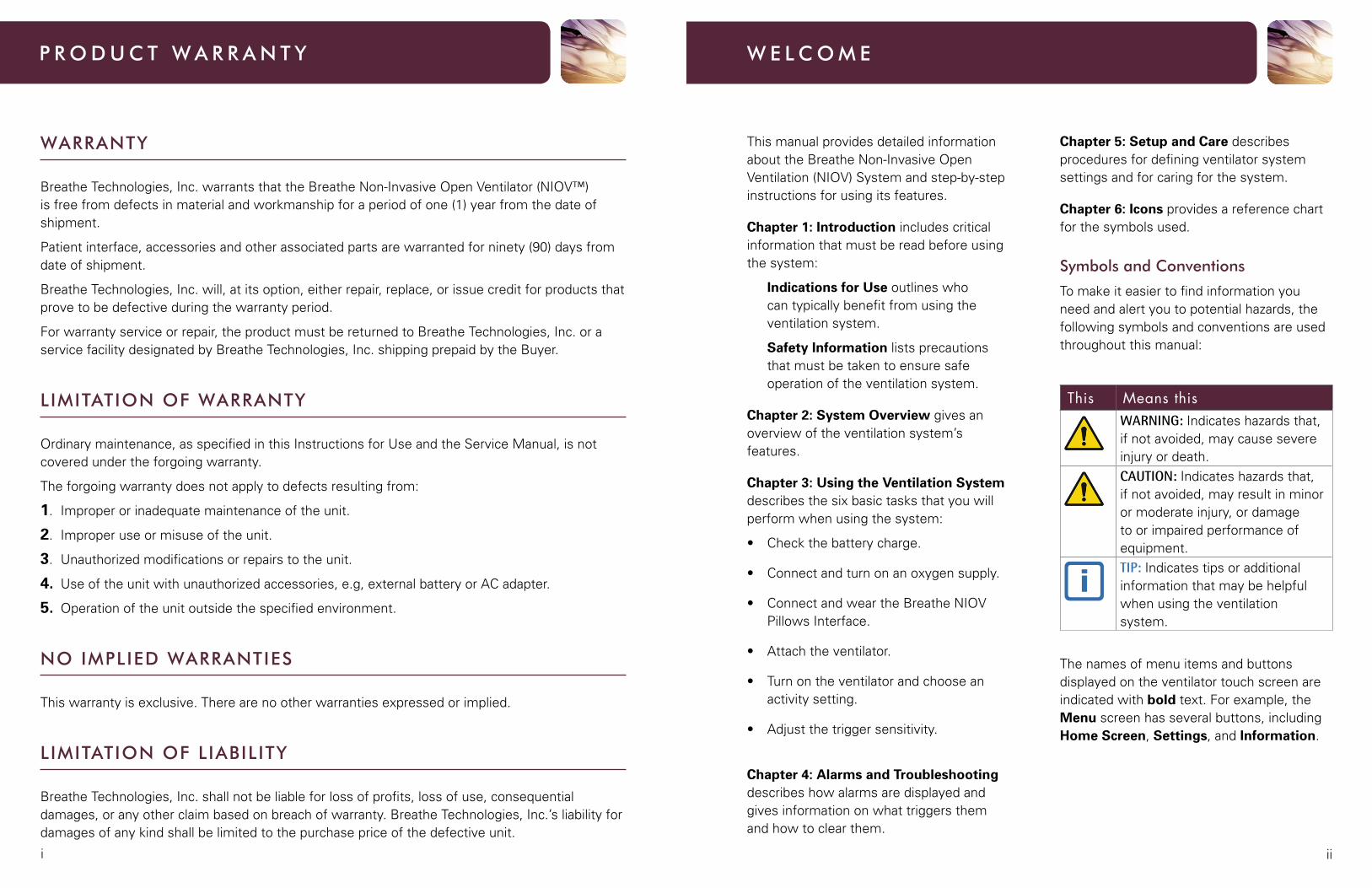
Symbols and Conventions
To make it easier to find information you need and alert you to potential hazards, the following symbols and conventions are used throughout this manual:
This Means thisWARNING: Indicates hazards that, if not avoided, may cause severe injuryordeath.CAUTION: Indicates hazards that, if not avoided, may result in minor ormoderateinjury,ordamageto or impaired performance of equipment.TIP: Indicates tips or additional information that may be helpful when using the ventilation system.
The names of menu items and buttons displayed on the ventilator touch screen are indicated with bold text. For example, the Menu screen has several buttons, including Home Screen, Settings, and Information.
W e l C o m e
WARRANTY
Breathe Technologies, Inc. warrants that the Breathe Non-Invasive Open Ventilator (NIOV™) is free from defects in material and workmanship for a period of one (1) year from the date of shipment.
Patient interface, accessories and other associated parts are warranted for ninety (90) days from date of shipment.
Breathe Technologies, Inc. will, at its option, either repair, replace, or issue credit for products that prove to be defective during the warranty period.
For warranty service or repair, the product must be returned to Breathe Technologies, Inc. or a service facility designated by Breathe Technologies, Inc. shipping prepaid by the Buyer.
lImITATIoN oF WARRANTY
Ordinary maintenance, as specified in this Instructions for Use and the Service Manual, is not covered under the forgoing warranty.
The forgoing warranty does not apply to defects resulting from:
1. Improper or inadequate maintenance of the unit.
2. Improper use or misuse of the unit.
3. Unauthorized modifications or repairs to the unit.
4. Useoftheunitwithunauthorizedaccessories,e.g,externalbatteryorACadapter.
5. Operation of the unit outside the specified environment.
No ImPlIeD WARRANTIeS
This warranty is exclusive. There are no other warranties expressed or implied.
lImITATIoN oF lIABIlITY
Breathe Technologies, Inc. shall not be liable for loss of profits, loss of use, consequential damages, or any other claim based on breach of warranty. Breathe Technologies, Inc.’s liability for damages of any kind shall be limited to the purchase price of the defective unit.
P R o D U C T W A R R A N T Y
iviii
The information contained in this document is of a proprietary and confidential nature and is intended only for the persons to whom it is directly transmitted by Breathe Technologies, Inc. No part of this manual may be reproduced or transmitted in any form or by any means, electronic or mechanical, including photocopying and recording, for any purpose without the express written permission of Breathe Technologies, Inc.
This document corresponds to the version/revision level effective at the time of delivery. Revisions to documentation are not automatically distributed. Please contact Breathe Technologies to order current revisions.
NIOV™ and Breathe. Move. Live.™ are trademarks of Breathe Technologies, Inc. For applicable US and Foreign Patent Coverage, see www.breathetechnologies.com/patents. All other products or services mentioned in this manual are identified by the trademark or service marks of their respective companies or organizations. Breathe Technologies, Inc. disclaims any responsibility for specifying which marks are owned by which companies or organizations.
CAUTION: Federal law (USA) restricts this device to sale by or on the order of a physician.
The Breathe NIOV Ventilator contains electrical components that must be disposed of according to the guidelines of the WEEE Directive (Waste in Electrical and Electronic Equipment), Directive 2002/96/EC. Follow local regulations when disposing the ventilator.
Breathe NIOV Ventilation System Patient Instructions for Use Copyright © 2012 by Breathe Technologies, Inc. All Rights Reserved
Technical Support and Customer Service
United States: 1-877-698-1326
Chapter 1: Introduction ________________1
Indications for Use ______________________2
Patient Participation _____________________2
Safety Information ______________________3
Chapter 2: System Overview ___________4
VentilationSystemComponents __________5
Breathe Pillows Interface ________________6
Ventilator Features ______________________6
Turning the Ventilator On and Off _________8
Touch Screen Features __________________9
Touch Screen Energy-Save Mode ________10
Chapter 3: Using the Ventilation System ______________________________11
Step1.ChecktheBatteryCharge ________12
Step2.ConnectandTurnonan Oxygen Supply ________________________13
Step3.ConnectandWearthe Pillows Interface _______________________16
Step4.AttachtheVentilator_____________19
Step 5. Turn On the Ventilator and ChooseanActivitySetting ______________19
Step6.AdjusttheTriggerSensitivity _____20
Chapter 4: Alarms and Troubleshooting 22
AudioAlarmSounds ___________________23
AlarmMessageDisplay_________________23
ActiveAlarmsWindow _________________24
SilencingandClearingAlarmsSummary __25
NIOVVentilationSystemAlarms _________26
AdditionalTroubleshootingSituations _____28
Chapter 5: Setup and Care_____________31
ChangingVentilatorSettings ____________32
SettingTimeandDate __________________33
Setting Vibration Mode _________________34
SettingAudioLoudness ________________35
AdjustingScreenBrightness ____________36
Viewing Software Version Information ____37
CaringfortheNIOVVentilationSystem ___37
Battery Retraining and Replacement _____41
Oxygen Supply Information _____________41
Chapter 6: Icons ______________________43
Index ________________________________47
C o N T e N T S
2
1Chapter
INtrOdUCtIONThis section includes the critical information that must be read
before using the system.
Indications for Use
ClinicalConsiderationsforUse
Patient Participation
Safety Information
INDICATIoNS FoR USe
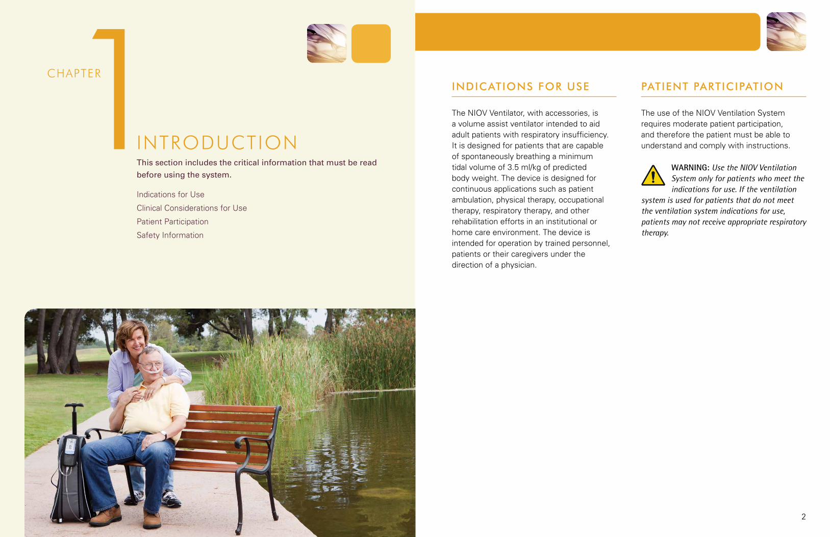
The NIOV Ventilator, with accessories, is a volume assist ventilator intended to aid adult patients with respiratory insufficiency. It is designed for patients that are capable of spontaneously breathing a minimum tidal volume of 3.5 ml/kg of predicted body weight. The device is designed for continuous applications such as patient ambulation, physical therapy, occupational therapy, respiratory therapy, and other rehabilitation efforts in an institutional or home care environment. The device is intended for operation by trained personnel, patients or their caregivers under the direction of a physician.
PATIeNT PARTICIPATIoN
The use of the NIOV Ventilation System requires moderate patient participation, and therefore the patient must be able to understand and comply with instructions.
WARNING: Use the NIOV Ventilation System only for patients who meet the indications for use. If the ventilation
system is used for patients that do not meet the ventilation system indications for use, patients may not receive appropriate respiratory therapy.

3
SYSTEM OVERVIEWThis section describes the basic parts and functions of the
NIOV Ventilation System.
Ventilation System Components
Breathe Pillows Interface
Ventilator Features
Turning the Ventilator On and Off
Touch Screen Features
Touch Screen Energy-Save Mode
2Chapter
1 I N T R o D U C T I o N
SAFeTY INFoRmATIoN
Before using the NIOV Ventilation System, you must be appropriately trained and must fully understand potential safety hazards. Read the following safety warnings and cautions in their entirety before using the ventilationsystem.Additionalwarningsand cautions can be found throughout this manual.
WARNING: The NIOV Ventilation System is not designed for patients who cannot spontaneously breathe or
who are fully dependent on mechanical ventilation.
Failure to read the manual may result in product misuse, which may cause equipment damage or patient mistreatment.
If the NIOV Ventilation System is not functioning correctly, you may not receive appropriate respiratory therapy. Always have an alternate means of oxygen therapy available.
Do not allow smoking near oxygen sources or near the ventilator and do not place oxygen sources or the ventilator near any source of direct heat because flammable materials burn more readily in the presence of oxygen.
If the NIOV Ventilation System is not functioning correctly, use your standard oxygen therapy and contact your health care provider.
CAUTION: Do not use the NIOV Ventilation System in magnetic resonance imaging (MRI) environments.
MRI equipment may cause electronic components in the ventilator to malfunction.
Do not submerge the ventilator in liquids or pour liquids on it. Liquids may cause components in the ventilator to malfunction.
Do not eat, drink, or chew gum while using the ventilator. Food or liquids that make contact with the ventilator may cause components in the ventilator to malfunction. Eating, drinking, or chewing gum may also increase the risk of choking.
When the ventilator is in use, keep it in a well-ventilated area to prevent it from overheating. The ventilator may overheat and be permanently damaged if it is used in an area that is not well ventilated.
65
2 S y S t e m O v e r v i e w
BReAThe PIlloWS INTeRFACe
The Breathe Pillows Interface for use with the ventilator is not included with the ventilation system components and is shipped separately. For instructions on how tofit,adjust,andconnecttheinterface,seethe section Using the NIOV Ventilation System in this manual and refer to the Breathe Pillows Interface Quick Start guide included with each interface.
WARNING: Use the NIOV Ventilation System only with the Pillows Interface. If the ventilation system is used with
another manufacturer’s interface, the ventilator may not function correctly and you may not receive appropriate respiratory therapy.
CAUTION: Use a Pillows Interface for a maximum of 30 days. If an interface is used for more than 30 days, its
performance may degrade and you may not receive adequate respiratory therapy.
Do not use a Pillows Interface that is cracked, odorous, broken, or kinked. If a damaged interface is used, you may not receive adequate respiratory therapy.
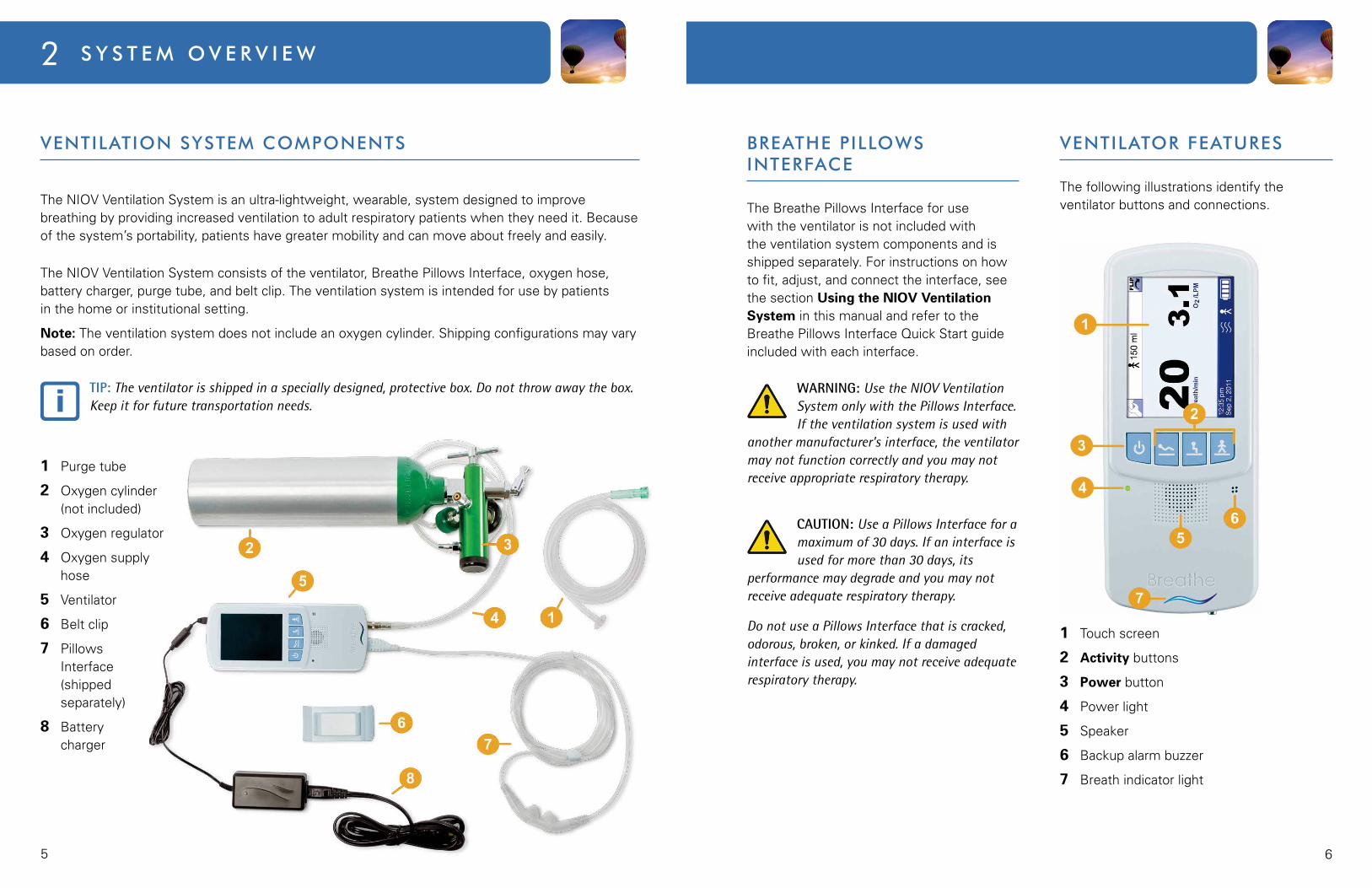
VeNTIlAToR FeATUReS
The following illustrations identify the ventilator buttons and connections.
1 Touch screen
2 Activity buttons
3 Power button
4 Power light
5 Speaker
6 Backup alarm buzzer
7 Breath indicator light
VeNTIlATIoN SYSTem ComPoNeNTS
The NIOV Ventilation System is an ultra-lightweight, wearable, system designed to improve breathing by providing increased ventilation to adult respiratory patients when they need it. Because of the system’s portability, patients have greater mobility and can move about freely and easily.
The NIOV Ventilation System consists of the ventilator, Breathe Pillows Interface, oxygen hose, battery charger, purge tube, and belt clip. The ventilation system is intended for use by patients in the home or institutional setting.
Note: The ventilation system does not include an oxygen cylinder. Shipping configurations may vary based on order.
TIP: The ventilator is shipped in a specially designed, protective box. Do not throw away the box. Keep it for future transportation needs.
1 Purge tube
2 Oxygen cylinder (not included)
3 Oxygen regulator
4 Oxygen supply hose
5 Ventilator
6 Belt clip
7 Pillows Interface (shipped separately)
8 Battery charger
87
2 S y S t e m O v e r v i e w
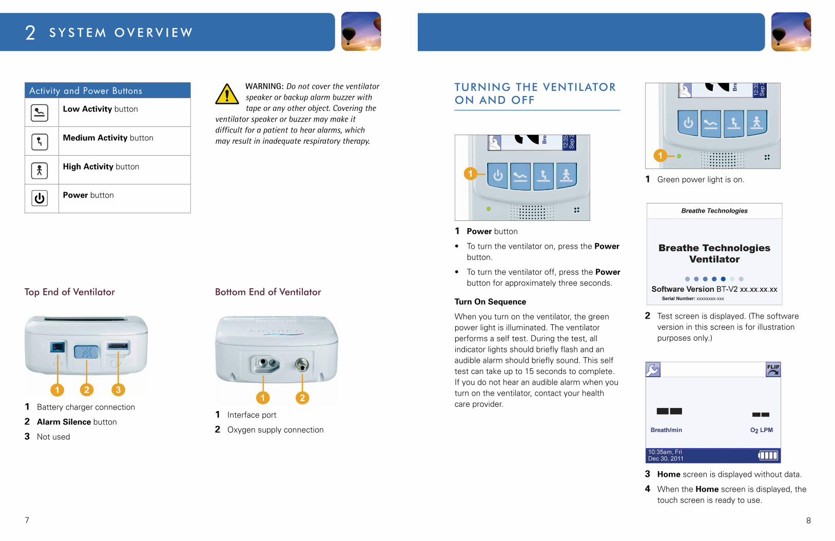
TURNINg The VeNTIlAToR oN AND oFF
1 Power button
• Toturntheventilatoron,pressthePower button.
• Toturntheventilatoroff,pressthePower button for approximately three seconds.
Turn On Sequence
Whenyouturnontheventilator,thegreenpower light is illuminated. The ventilator performsaselftest.Duringthetest,allindicator lights should briefly flash and an audible alarm should briefly sound. This self test can take up to 15 seconds to complete. If you do not hear an audible alarm when you turn on the ventilator, contact your health care provider.
1 Green power light is on.
2 Test screen is displayed. (The software version in this screen is for illustration purposes only.)
3 Home screen is displayed without data.
4 WhentheHome screen is displayed, the touch screen is ready to use.
Activity and Power Buttons
Low Activity button
Medium Activity button
High Activity button
Power button
WARNING: Do not cover the ventilator speaker or backup alarm buzzer with tape or any other object. Covering the
ventilator speaker or buzzer may make it difficult for a patient to hear alarms, which may result in inadequate respiratory therapy.
Top end of Ventilator
1 Battery charger connection
2 Alarm Silence button
3 Not used
Bottom end of Ventilator
1 Interface port
2 Oxygen supply connection

109
2 S y S t e m O v e r v i e w
menu Screen
Use the Menu screen to go to the Settings menu, get information about the software version of the ventilator and ventilator use, or go back to the Home screen.
To get to the Menu screen, on any ventilator screen, touch the Wrench button.
1 Screen title.
2 Touch to go to the Home screen.
3 Touch to go to the Settings screen for Trigger Sensitivity, and Utilities.
4 Touch to go to the Software Version screen for software version and total use time.
Moving Between the Home Screen and Menu Screen
1 Touch the Wrench button to go to the Menu screen.
2 Touch the Home Screen button to go to the Home screen.
ToUCh SCReeN FeATUReS
The NIOV Ventilation System uses a touch screen for setting up the ventilator, monitoring patient data, and displaying alarm information. To use the touch screen, simply touch a screen button or an area of the screenyouwanttomakeactive.Anaudible“click” indicates the feature you touch is activated.
There are two main ventilator screens: the Home screen and the Menu screen.
home Screen
Whenyouturnontheventilator,afteritcompletes a self test, the touch screen displays the Homescreen.Aftertheoxygensupply is connected and the patient is wearing the Pillows Interface, when you press a ventilator Activity button, the Home screen displays patient oxygen flow rate and breath rate.
The following illustration shows the buttons, icons, and information displayed on the Home screen.
1 Touch the Wrench button to go to the Menu screen.
2 CurrentActivity icon and augmentation volume.
3 Touch the Flip button to flip the screen 180°.
4 Currentbreathsperminute(BPM).
5 Averageoxygenflowinlitersperminute,based on activity setting and patient’s current breath rate.
6 Battery Charge icon.
7 CurrentActivity icon. Use the ventilator Activity buttons to change an activity setting.
8 Vibration icon indicating ventilator is in vibration mode.
9 Time and date display.
Note: The Wrench and Flip buttons at the top of the screen and the time and date, current Activity icon, and Battery Charge icon at the bottom are displayed on all screens.
ToUCh SCReeN eNeRgY-SAVe moDe
Aftertwominuteswithnouserinteraction,thetouchscreenautomaticallyentersenergy-savemode and dims the screen. Touching the screen again will reactivate it and display the Home screen.
12
3Chapter
USINg the VeNtIlatION SyStemThis section describes the six basic steps you need to perform to
set up and use the NIOV Ventilation System.
Step1.ChecktheBatteryCharge
Step2.ConnectandTurnonanOxygenSupply
Step3.ConnectandWearthePillowsInterface
Step4.AttachtheVentilator
Step5.TurnOntheVentilatorandChooseanActivitySetting
Step6.AdjusttheTriggerSensitivity
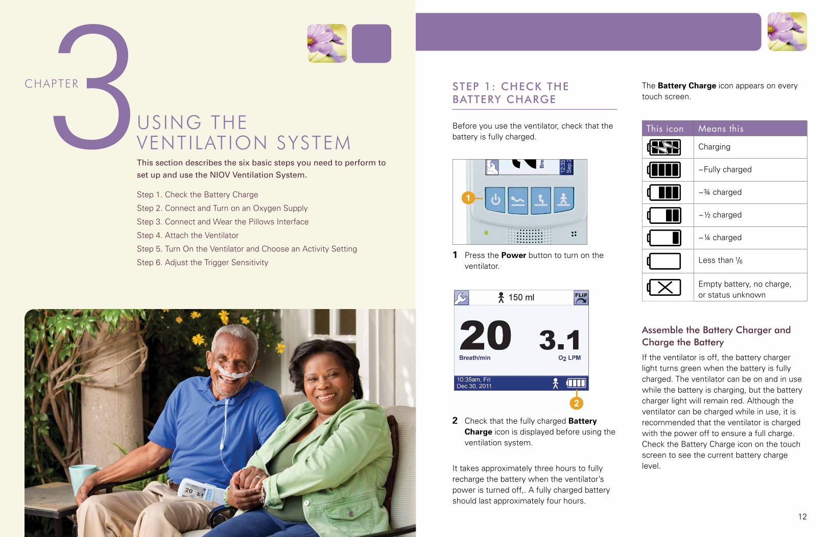
STeP 1: CheCk The BATTeRY ChARge
Before you use the ventilator, check that the battery is fully charged.
1 Press the Power button to turn on the ventilator.
2 CheckthatthefullychargedBattery Charge icon is displayed before using the ventilation system.
It takes approximately three hours to fully recharge the battery when the ventilator’s poweristurnedoff,.Afullychargedbatteryshould last approximately four hours.
The Battery Charge icon appears on every touch screen.
This icon Means this
Charging
~Fully charged
~¾ charged
~½ charged
~¼ charged
Less than 1/6
Empty battery, no charge, or status unknown
Assemble the Battery Charger and Charge the Battery
If the ventilator is off, the battery charger light turns green when the battery is fully charged. The ventilator can be on and in use while the battery is charging, but the battery chargerlightwillremainred.Althoughtheventilator can be charged while in use, it is recommended that the ventilator is charged with the power off to ensure a full charge. ChecktheBatteryChargeicononthetouchscreen to see the current battery charge level.
1413
3 U s i n g t h e V e n t i l at i o n s y s t e m
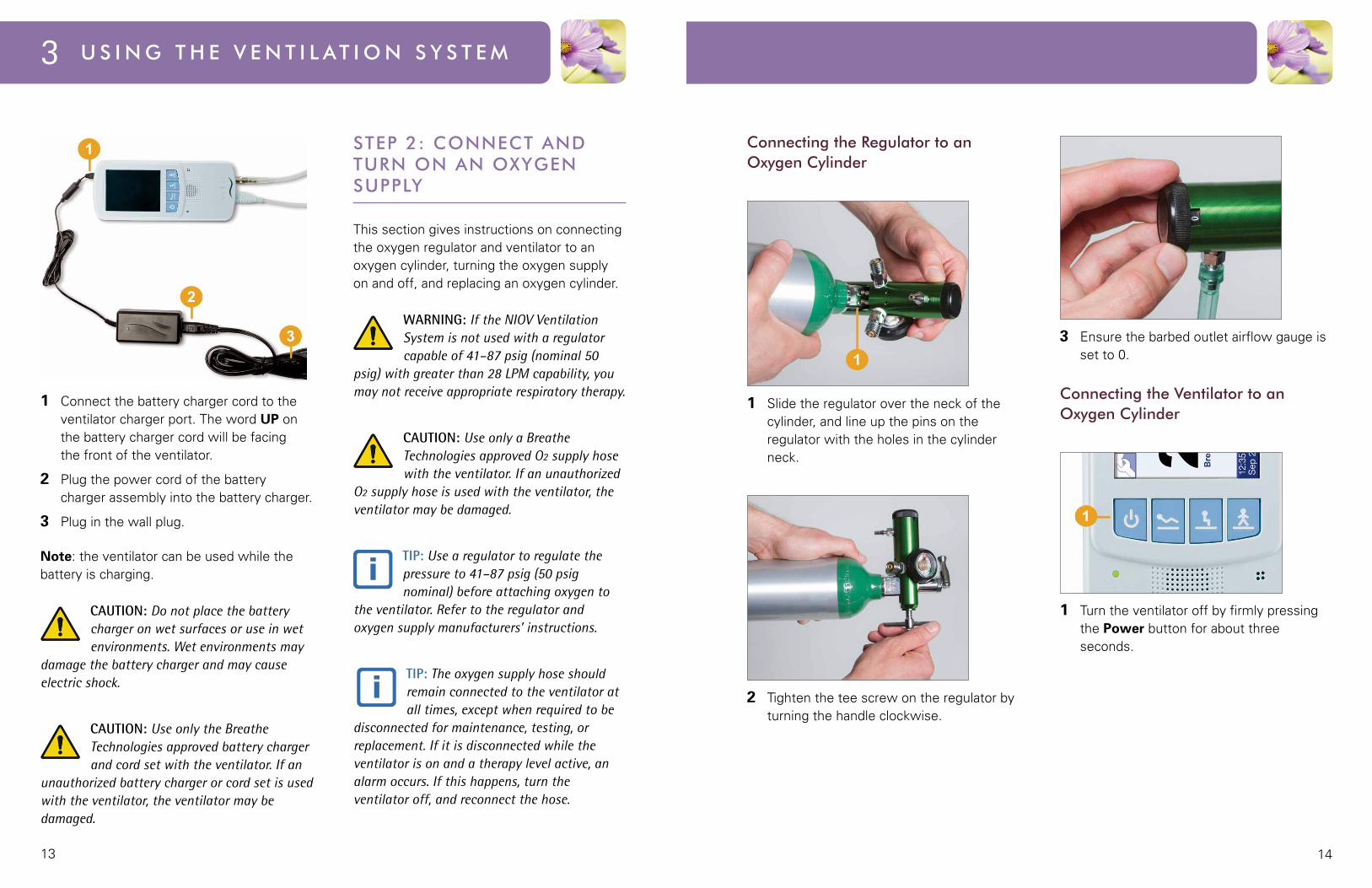
1 Connectthebatterychargercordtotheventilator charger port. The word UP on the battery charger cord will be facing the front of the ventilator.
2 Plug the power cord of the battery charger assembly into the battery charger.
3 Plug in the wall plug.
Note: the ventilator can be used while the battery is charging.
CAUTION: Do not place the battery charger on wet surfaces or use in wet environments. Wet environments may
damage the battery charger and may cause electric shock.
CAUTION: Use only the Breathe Technologies approved battery charger and cord set with the ventilator. If an
unauthorized battery charger or cord set is used with the ventilator, the ventilator may be damaged.
STeP 2: CoNNeCT AND TURN oN AN oxYgeN SUPPlY
This section gives instructions on connecting the oxygen regulator and ventilator to an oxygen cylinder, turning the oxygen supply on and off, and replacing an oxygen cylinder.
WARNING: If the NIOV Ventilation System is not used with a regulator capable of 41–87 psig (nominal 50
psig) with greater than 28 LPM capability, you may not receive appropriate respiratory therapy.
CAUTION: Use only a Breathe Technologies approved O2 supply hose with the ventilator. If an unauthorized
O2 supply hose is used with the ventilator, the ventilator may be damaged.
TIP: Use a regulator to regulate the pressure to 41–87 psig (50 psig nominal) before attaching oxygen to
the ventilator. Refer to the regulator and oxygen supply manufacturers’ instructions.
TIP: The oxygen supply hose should remain connected to the ventilator at all times, except when required to be
disconnected for maintenance, testing, or replacement. If it is disconnected while the ventilator is on and a therapy level active, an alarm occurs. If this happens, turn the ventilator off, and reconnect the hose.
Connecting the Regulator to an oxygen Cylinder
1 Slide the regulator over the neck of the cylinder, and line up the pins on the regulator with the holes in the cylinder neck.
2 Tighten the tee screw on the regulator by turning the handle clockwise.
3 Ensure the barbed outlet airflow gauge is set to 0.
Connecting the Ventilator to an oxygen Cylinder
1 Turn the ventilator off by firmly pressing the Power button for about three seconds.

1615
3 U s i n g t h e V e n t i l at i o n s y s t e m
2 Push the small oxygen supply hose connector onto the oxygen supply connection until it snaps into place.
3 Connectthegreenoxygensupplyhoseconnector to the oxygen regulator by turning it clockwise.
4 Withtheventilatorpoweroffandthe oxygen supply hose connected
to the ventilator and oxygen supply, follow the regulator and oxygen supply manufacturers’ instructions for turning on the oxygen supply.
Replacing an oxygen Cylinder
Whenanoxygencylinderneedstobereplaced:
1 Turn the ventilator off by firmly pressing the Power button for at least three seconds.
2 Follow the oxygen and regulator manufacturers’ instructions for shutting off the oxygen supply.
3 Disconnecttheventilatoroxygensupplyhose from the oxygen supply.
4 Connecttheventilatoroxygensupplyhose to a new oxygen cylinder.
5 Follow the oxygen and regulator manufacturers’ instructions for turning on the oxygen cylinder.
1 Tubefitadjustor
2 Ventilator connector
3 Interface tubing
4 Interface pillows
Connecting the Interface to the Ventilator
1 Turn off the ventilator.
2 Plug the interface into the ventilator port.
STeP 3: CoNNeCT AND WeAR The PIlloWS INTeRFACe
Before using the Pillows Interface, visually inspect it for damage.
The interface comes in four sizes: extra small, small, medium, and large. Your health care provider determines what size is best for you. The interface assembly is packaged clean but not sterile.
1817
3 U s i n g t h e V e n t i l at i o n s y s t e m
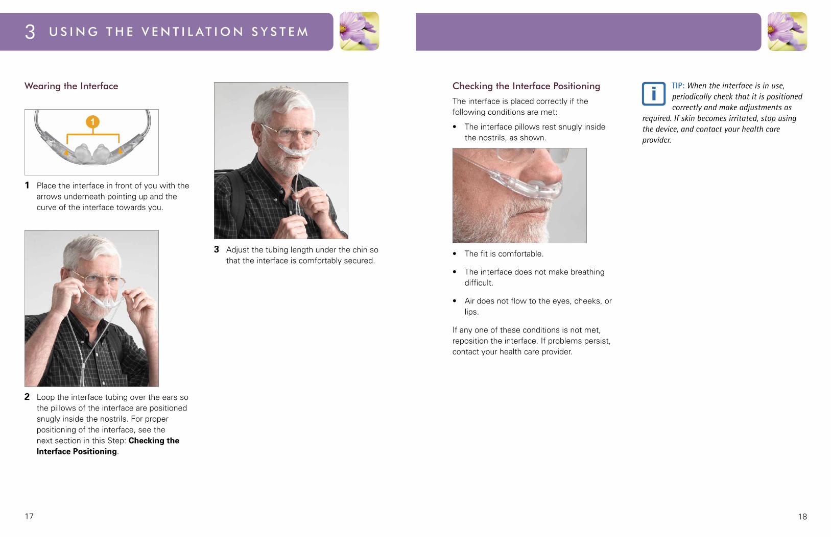
Wearing the Interface
1 Place the interface in front of you with the arrows underneath pointing up and the curve of the interface towards you.
2 Loop the interface tubing over the ears so the pillows of the interface are positioned snugly inside the nostrils. For proper positioning of the interface, see the next section in this Step: Checking the Interface Positioning.
3 Adjustthetubinglengthunderthechinsothat the interface is comfortably secured.
Checking the Interface Positioning
The interface is placed correctly if the following conditions are met:
• Theinterfacepillowsrestsnuglyinsidethe nostrils, as shown.
• Thefitiscomfortable.
• Theinterfacedoesnotmakebreathingdifficult.
• Airdoesnotflowtotheeyes,cheeks,orlips.
If any one of these conditions is not met, reposition the interface. If problems persist, contact your health care provider.
TIP: When the interface is in use, periodically check that it is positioned correctly and make adjustments as
required. If skin becomes irritated, stop using the device, and contact your health care provider.
2019
3 U s i n g t h e V e n t i l at i o n s y s t e m
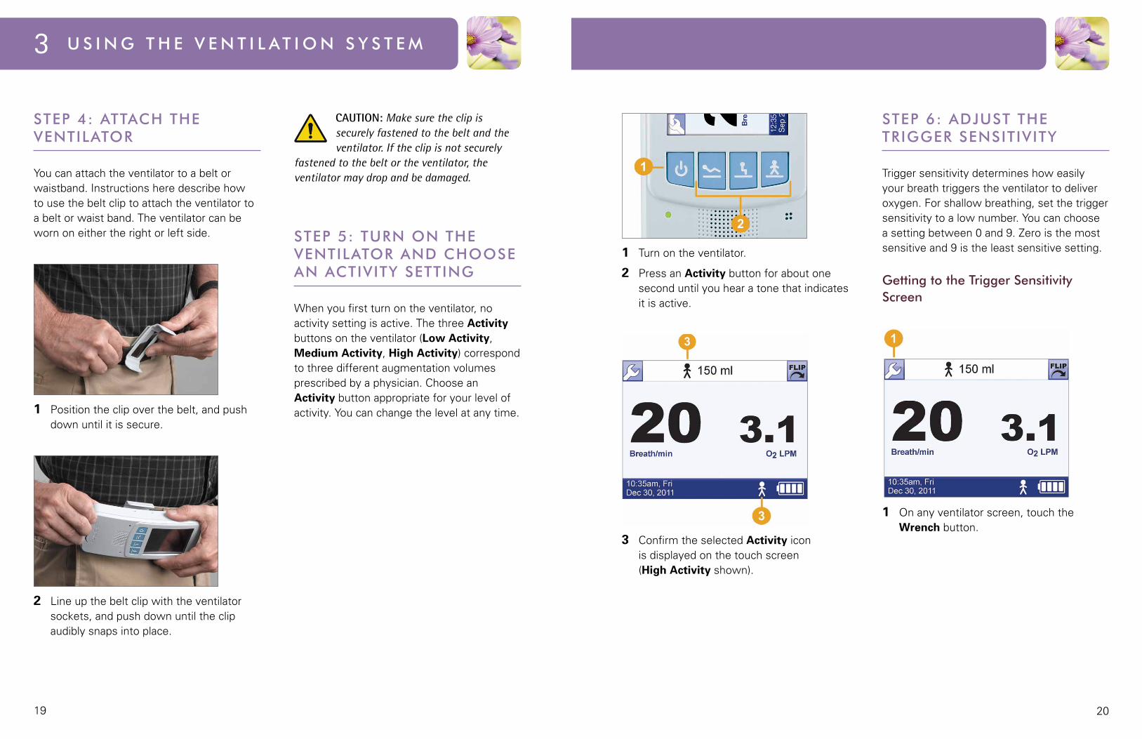
STeP 4: ATTACh The VeNTIlAToR
You can attach the ventilator to a belt or waistband. Instructions here describe how to use the belt clip to attach the ventilator to a belt or waist band. The ventilator can be worn on either the right or left side.
1 Position the clip over the belt, and push down until it is secure.
2 Line up the belt clip with the ventilator sockets, and push down until the clip audibly snaps into place.
CAUTION: Make sure the clip is securely fastened to the belt and the ventilator. If the clip is not securely
fastened to the belt or the ventilator, the ventilator may drop and be damaged.
STeP 5: TURN oN The VeNTIlAToR AND ChooSe AN ACTIVITY SeTTINg
Whenyoufirstturnontheventilator,noactivity setting is active. The three Activity buttons on the ventilator (Low Activity, Medium Activity, High Activity) correspond to three different augmentation volumes prescribedbyaphysician.ChooseanActivity button appropriate for your level of activity. You can change the level at any time.
1 Turn on the ventilator.
2 Press an Activity button for about one second until you hear a tone that indicates it is active.
3 ConfirmtheselectedActivity icon is displayed on the touch screen (High Activity shown).
STeP 6: ADjUST The TRIggeR SeNSITIVITY
Trigger sensitivity determines how easily your breath triggers the ventilator to deliver oxygen. For shallow breathing, set the trigger sensitivity to a low number. You can choose a setting between 0 and 9. Zero is the most sensitive and 9 is the least sensitive setting.
getting to the Trigger Sensitivity Screen
1 On any ventilator screen, touch the Wrench button.
21
4Chapter
alarmS aNd trOUBleShOOtINgThis section describes the alarm functions and possible
troubleshooting solutions.
AudioAlarmSounds
AlarmMessageDisplay
ActiveAlarmsWindow
SilencingandClearingAlarmsSummary
NIOVVentilationSystemAlarms
AdditionalTroubleshootingSituations
3 U S I N g T h e V e N T I l AT I o N S Y S T e m
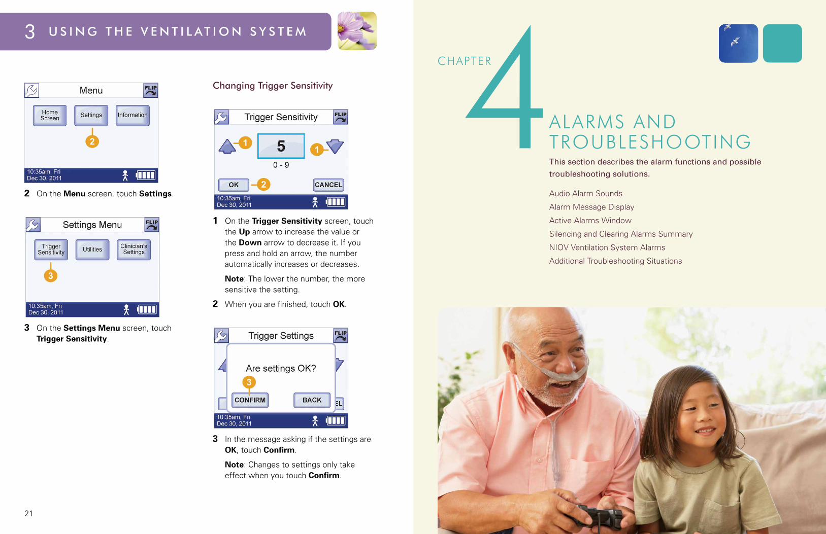
2 On the Menu screen, touch Settings.
3 On the Settings Menu screen, touch Trigger Sensitivity.
Changing Trigger Sensitivity
1 On the Trigger Sensitivity screen, touch the Up arrow to increase the value or the Down arrow to decrease it. If you press and hold an arrow, the number automatically increases or decreases.
Note: The lower the number, the more sensitive the setting.
2 Whenyouarefinished,touchOK.
3 In the message asking if the settings are OK, touch Confirm.
Note:Changestosettingsonlytakeeffect when you touch Confirm.
2423
4 A l A r m s A n d T r o u b l e s h o o T i n g
ACTIVe AlARmS WINDoW
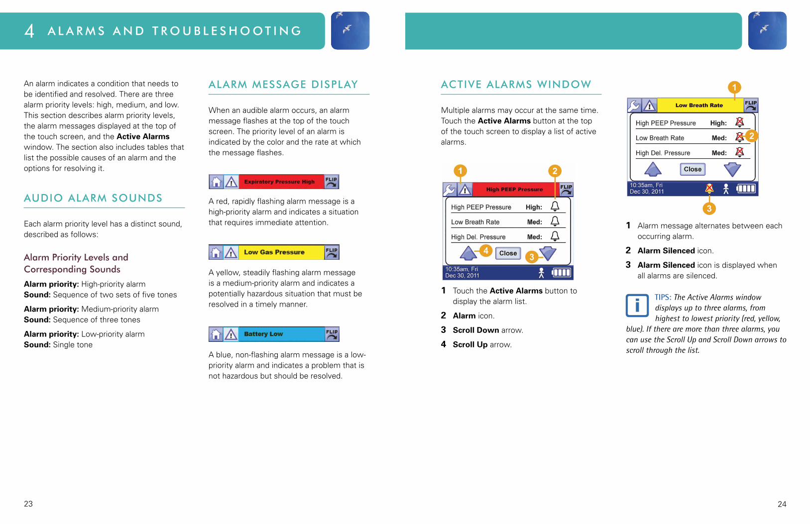
Multiple alarms may occur at the same time. Touch the Active Alarms button at the top of the touch screen to display a list of active alarms.
1 Touch the Active Alarms button to display the alarm list.
2 Alarm icon.
3 Scroll Down arrow.
4 Scroll Up arrow.
1 Alarmmessagealternatesbetweeneachoccurring alarm.
2 Alarm Silenced icon.
3 Alarm Silenced icon is displayed when all alarms are silenced.
TIPS: The Active Alarms window displays up to three alarms, from highest to lowest priority (red, yellow,
blue). If there are more than three alarms, you can use the Scroll Up and Scroll Down arrows to scroll through the list.
Analarmindicatesaconditionthatneedstobe identified and resolved. There are three alarm priority levels: high, medium, and low. This section describes alarm priority levels, the alarm messages displayed at the top of the touch screen, and the Active Alarms window. The section also includes tables that list the possible causes of an alarm and the options for resolving it.
AUDIo AlARm SoUNDS
Each alarm priority level has a distinct sound, described as follows:
Alarm Priority levels and Corresponding Sounds
Alarm priority: High-priority alarm Sound: Sequence of two sets of five tones
Alarm priority: Medium-priority alarm Sound: Sequence of three tones
Alarm priority: Low-priority alarm Sound: Single tone
AlARm meSSAge DISPlAY
Whenanaudiblealarmoccurs,analarmmessage flashes at the top of the touch screen. The priority level of an alarm is indicated by the color and the rate at which the message flashes.
Ared,rapidlyflashingalarmmessageisahigh-priority alarm and indicates a situation that requires immediate attention.
Ayellow,steadilyflashingalarmmessageis a medium-priority alarm and indicates a potentially hazardous situation that must be resolved in a timely manner.
Ablue,non-flashingalarmmessageisalow-priority alarm and indicates a problem that is not hazardous but should be resolved.
2625
4 A l A r m s A n d T r o u b l e s h o o T i n g
SIleNCINg AND CleARINg AlARmS SUmmARY
Silencing and clearing alarms is a multi-step process that depends on alarm priority and how many alarms are active.
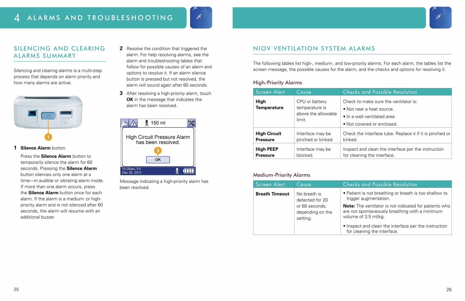
1 Silence Alarm button.
Press the Silence Alarm button to temporarily silence the alarm for 60 seconds. Pressing the Silence Alarm button silences only one alarm at a time—in audible or vibrating alarm mode. If more than one alarm occurs, press the Silence Alarm button once for each alarm. If the alarm is a medium- or high-priority alarm and is not silenced after 60 seconds, the alarm will resume with an additional buzzer.
2 Resolve the condition that triggered the alarm. For help resolving alarms, see the alarm and troubleshooting tables that follow for possible causes of an alarm and options to resolve it. If an alarm silence button is pressed but not resolved, the alarm will sound again after 60 seconds.
3 Afterresolvingahigh-priorityalarm,touchOK in the message that indicates the alarm has been resolved.
Message indicating a high-priority alarm has been resolved.
NIoV VeNTIlATIoN SYSTem AlARmS
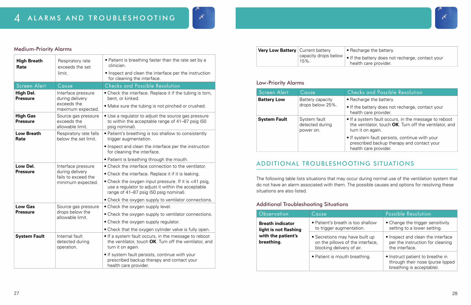
The following tables list high-, medium-, and low-priority alarms. For each alarm, the tables list the screen message, the possible causes for the alarm, and the checks and options for resolving it.
high-Priority Alarms
Screen Alert Cause Checks and Possible Resolution
High Temperature
CPUorbatterytemperature is above the allowable limit.
Checktomakesuretheventilatoris:
•Notnearaheatsource.
•Inawellventilatedarea.
•Notcoveredorenclosed.
High Circuit Pressure
Interface may be pinched or kinked.
Checktheinterfacetube.Replaceitifitispinchedorkinked.
High PEEP Pressure
Interface may be blocked.
Inspect and clean the interface per the instruction for cleaning the interface.
medium-Priority Alarms
Screen Alert Cause Checks and Possible Resolution
Breath Timeout No breath is detected for 20 or 60 seconds, depending on the setting.
•Patientisnotbreathingorbreathistooshallowtotrigger augmentation.
Note: The ventilator is not indicated for patients who are not spontaneously breathing with a minimum volume of 3.5 ml/kg.
•Inspectandcleantheinterfacepertheinstructionfor cleaning the interface.
2827
4 A l A r m s A n d T r o u b l e s h o o T i n g
High Breath Rate
Respiratory rate exceeds the set limit.
•Patientisbreathingfasterthantheratesetbyaclinician.
•Inspectandcleantheinterfacepertheinstructionfor cleaning the interface.
Screen Alert Cause Checks and Possible Resolution High Del. Pressure
Interface pressure during delivery exceeds the maximum expected.
•Checktheinterface.Replaceitifthetubingistorn,bent, or kinked.
•Makesurethetubingisnotpinchedorcrushed.
High Gas Pressure
Source gas pressure exceeds the allowable limit.
•Usearegulatortoadjustthesourcegaspressureto within the acceptable range of 41–87 psig (50 psig nominal).
Low Breath Rate
Respiratory rate falls below the set limit.
•Patient’sbreathingistooshallowtoconsistentlytrigger augmentation.
•Inspectandcleantheinterfacepertheinstructionfor cleaning the interface.
•Patientisbreathingthroughthemouth.Low Del. Pressure
Interface pressure during delivery fails to exceed the minimum expected.
•Checktheinterfaceconnectiontotheventilator.
•Checktheinterface.Replaceitifitisleaking.
•Checktheoxygeninputpressure.Ifitis<41psig,usearegulatortoadjustitwithintheacceptablerange of 41–87 psig (50 psig nominal).
•Checktheoxygensupplytoventilatorconnections.Low Gas Pressure
Source gas pressure drops below the allowable limit.
•Checktheoxygensupplylevel.
•Checktheoxygensupplytoventilatorconnections.
•Checktheoxygensupplyregulator.
•Checkthattheoxygencylindervalveisfullyopen.System Fault Internal fault
detected during operation.
•Ifasystemfaultoccurs,inthemessagetorebootthe ventilator, touch OK. Turn off the ventilator, and turn it on again.
•Ifsystemfaultpersists,continuewithyourprescribed backup therapy and contact your health care provider.
Very Low Battery Currentbatterycapacity drops below 15%.
•Rechargethebattery.
•Ifthebatterydoesnotrecharge,contactyourhealth care provider.
low-Priority Alarms
Screen Alert Cause Checks and Possible ResolutionBattery Low Battery capacity
drops below 25%.•Rechargethebattery.
•Ifthebatterydoesnotrecharge,contactyourhealth care provider.
System Fault System fault detected during power on.
•Ifasystemfaultoccurs,inthemessagetorebootthe ventilator, touch OK. Turn off the ventilator, and turn it on again.
•Ifsystemfaultpersists,continuewithyourprescribed backup therapy and contact your health care provider.
ADDITIoNAl TRoUBleShooTINg SITUATIoNS
The following table lists situations that may occur during normal use of the ventilation system that do not have an alarm associated with them. The possible causes and options for resolving these situations are also listed.
Additional Troubleshooting Situations
Observation Cause Possible Resolution
Breath indicator light is not flashing with the patient’s breathing.
•Patient’sbreathistooshallowto trigger augmentation.
•Changethetriggersensitivitysetting to a lower setting.
•Secretionsmayhavebuiltupon the pillows of the interface, blocking delivery of air.
•Inspectandcleantheinterfaceper the instruction for cleaning the interface.
•Patientismouthbreathing. •Instructpatienttobreatheinthrough their nose (purse lipped breathing is acceptable).
medium-Priority Alarms

3029
4 A l A r m s A n d T r o u b l e s h o o T i n g
Breath indicator light is not flashing.
•AventilatorActivity button has not been pressed.
•Secretionsmayhavebuiltupon the pillows of the interface, blocking delivery of air.
•PressanActivity button.
•Inspectandcleantheinterfaceper the instruction for cleaning the interface.
Buzzer sounds continuously at a constant pitch for two minutes or more.
•Theventilatorbatteryisinternally disconnected.
•Thebackupbuzzerwillsoundfor two to five minutes before it is silenced.
•Contactyourhealthcareprovider.
Gas delivery is causing coughing or irritation in airway.
•Interfaceisnotpositionedcorrectly.
•Ifsymptomspersist,stoptreatment with the ventilator, and contact your physician.
No volume output. •Oxygensupplyisdisconnected.
•Oxygensupplyisempty.
•Ventilatorisnoton.
•Batteryisdepleted.
•Ventilatorisinoperative.
•Reconnecttheoxygensupply.
•Replacetheoxygensupply.
•Turntheventilatoron.
•Rechargethebattery.
•Ifthereisnovolumeoutput,contact your health care provider.
Oxygen supply does not last as long as expected.
•Userbreathrateishigherthanexpected.
•Oxygensupplyisnotfullatthestart of use.
•Thegasregulatorisnotproperlyconnected to the oxygen cylinder.
•Obtainanewoxygensupply.
•Reconnectthegasregulatortothe oxygen cylinder.
Ventilator battery does not last as long as expected after a recharge.
•Batteryisnotchargedcompletely.
•Batterylifeisnearingitsend.
•Batteryhasbecomeuntrained.
•Rechargebattery.
•Contactyourhealthcareprovider.
•Retrainthebattery,asshowninsection 5.
Ventilator is autocycling (delivering gas without being triggered by the patient’s breathing or delivering gas multiple times during one breath).
•Secretionshavebuiltuponthepillows of the interface.
•Ventilatoristriggeredbymovement of the interface.
•Ventilatorisinbreathtimeout mode, with timeout augmentation set to 12 BPM.
•Inspectandcleantheinterfaceper the instruction for cleaning the interface.
•Adjusttriggersensitivitytoahigher number.
Ventilator is triggering during exhalation.
•Secretionshavebuiltuponthepillows of the interface.
•Inspectandcleantheinterfaceper the instruction for cleaning the interface.
Ventilator sometimes misses breaths.
•Userisbreathingfasterthan 40 BPM.
•Secretionshavebuiltuponthepillows of the interface.
•Itisnormalfortheventilatortolimit augmentation to less than 40 BPM.
•Inspectandcleantheinterfaceper the instruction for cleaning the interface.
Ventilator sounds like it is triggering, but no gas is being delivered.
•Nooxygensupplyisconnected. •Reconnectoxygensupply.
Observation Cause Possible Resolution Observation Cause Possible Resolution
Additional Troubleshooting Situations
32
5Chapter
SetUp aNd CareThis section describes how to change settings using the Utilities
menu and instructions on basic care of the system.
ChangingVentilatorSettings
SettingTimeandDate
Setting Vibration Mode
SettingAudioLoudness
AdjustingScreenBrightness
Viewing Software Version Information
CaringfortheNIOVVentilationSystem
Battery Retraining and Replacement
Oxygen Supply Information
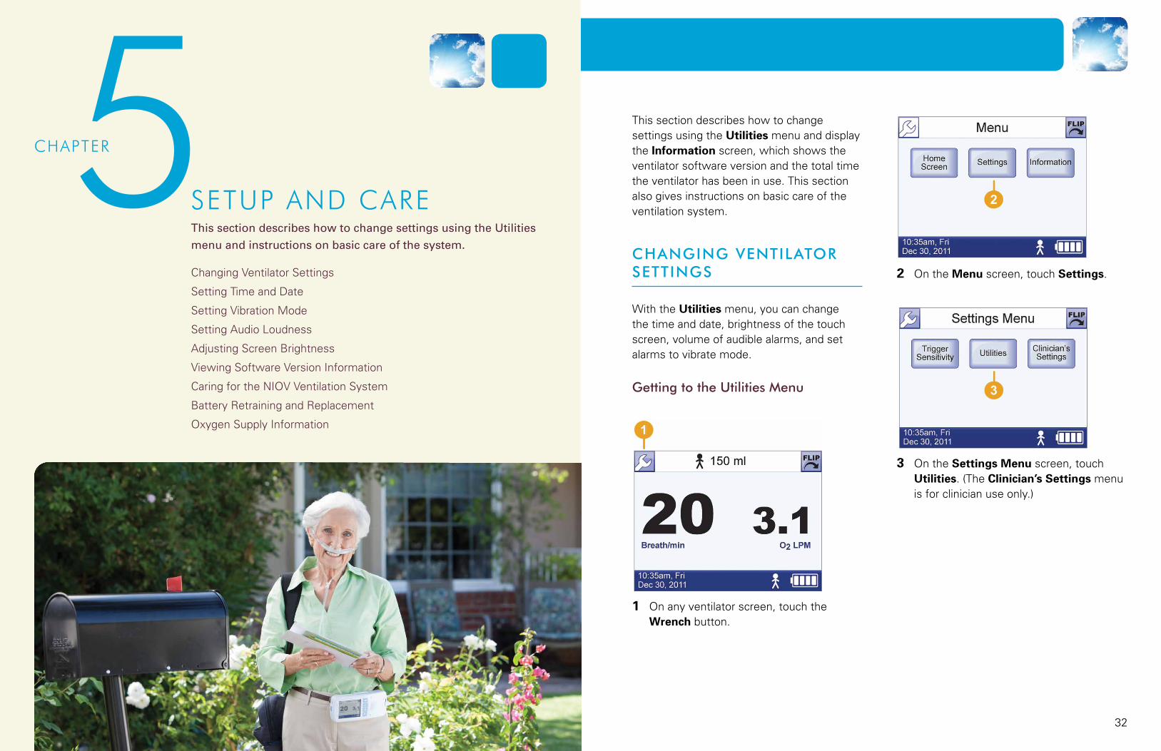
This section describes how to change settings using the Utilities menu and display the Information screen, which shows the ventilator software version and the total time the ventilator has been in use. This section also gives instructions on basic care of the ventilation system.
ChANgINg VeNTIlAToR SeTTINgS
WiththeUtilities menu, you can change the time and date, brightness of the touch screen, volume of audible alarms, and set alarms to vibrate mode.
getting to the Utilities menu
1 On any ventilator screen, touch the Wrench button.
2 On the Menu screen, touch Settings.
3 On the Settings Menu screen, touch Utilities. (The Clinician’s Settings menu is for clinician use only.)
3433
5 s e t u p a n d c a r e
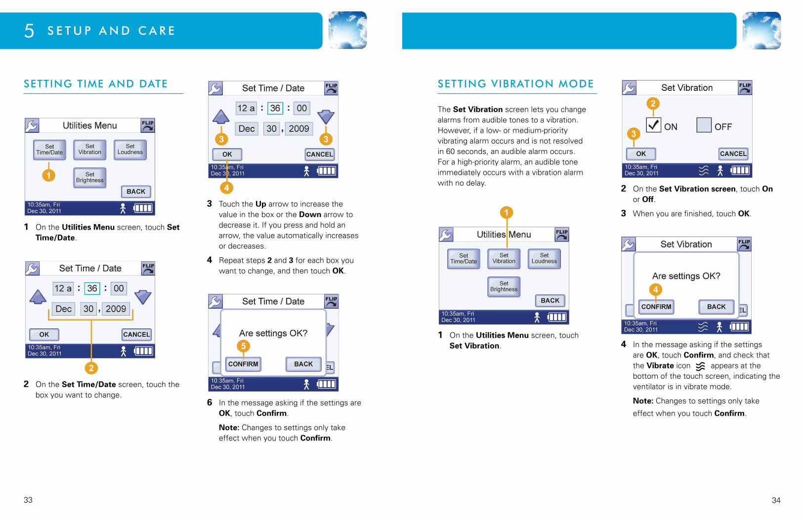
SeTTINg TIme AND DATe
1 On the Utilities Menu screen, touch Set Time/Date.
2 On the Set Time/Date screen, touch the box you want to change.
3 Touch the Up arrow to increase the value in the box or the Down arrow to decrease it. If you press and hold an arrow, the value automatically increases or decreases.
4 Repeat steps 2 and 3 for each box you want to change, and then touch OK.
6 In the message asking if the settings are OK, touch Confirm.
Note:Changestosettingsonlytakeeffect when you touch Confirm.
SeTTINg VIBRATIoN moDe
The Set Vibration screen lets you change alarms from audible tones to a vibration. However, if a low- or medium-priority vibrating alarm occurs and is not resolved in 60 seconds, an audible alarm occurs. For a high-priority alarm, an audible tone immediately occurs with a vibration alarm with no delay.
1 On the Utilities Menu screen, touch Set Vibration.
2 On the Set Vibration screen, touch On or Off.
3 Whenyouarefinished,touchOK.
4 In the message asking if the settings are OK, touch Confirm, and check that the Vibrate icon appears at the bottom of the touch screen, indicating the ventilator is in vibrate mode.
Note:Changestosettingsonlytake
effect when you touch Confirm.
3635
5 s e t u p a n d c a r e
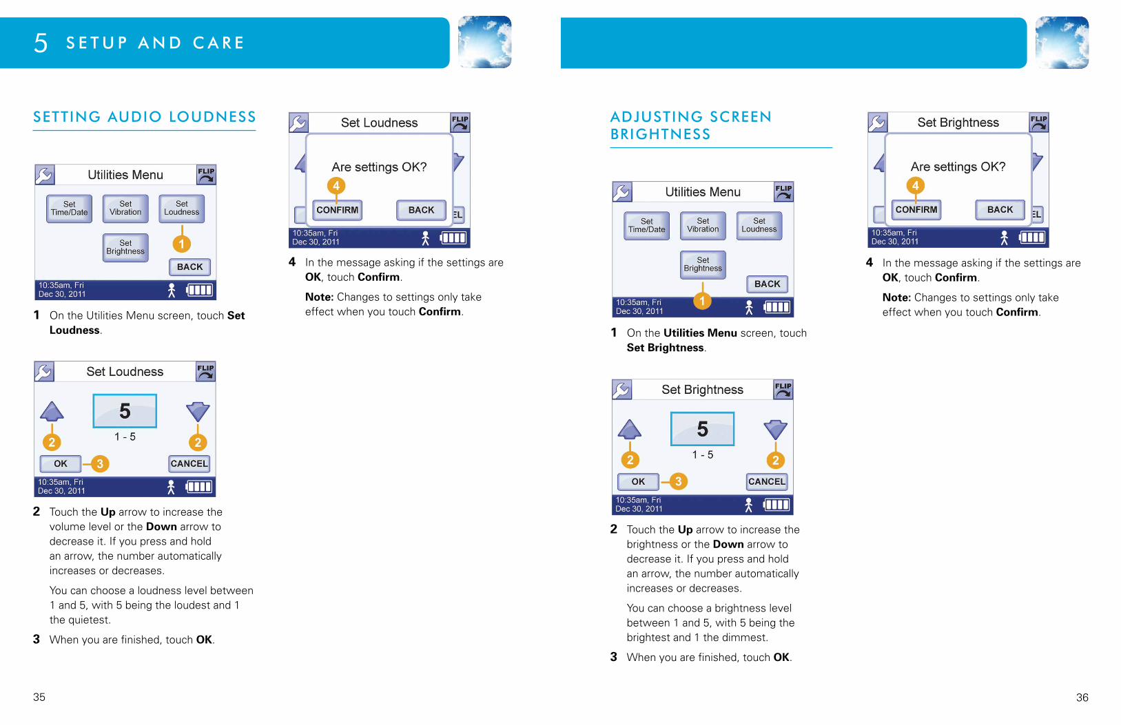
SeTTINg AUDIo loUDNeSS
1 On the Utilities Menu screen, touch Set Loudness.
2 Touch the Up arrow to increase the volume level or the Down arrow to decrease it. If you press and hold an arrow, the number automatically increases or decreases.
You can choose a loudness level between 1 and 5, with 5 being the loudest and 1 the quietest.
3 Whenyouarefinished,touchOK.
4 In the message asking if the settings are OK, touch Confirm.
Note:Changestosettingsonlytakeeffect when you touch Confirm.
ADjUSTINg SCReeN BRIghTNeSS
1 On the Utilities Menu screen, touch Set Brightness.
2 Touch the Up arrow to increase the brightness or the Down arrow to decrease it. If you press and hold an arrow, the number automatically increases or decreases.
You can choose a brightness level between 1 and 5, with 5 being the brightest and 1 the dimmest.
3 Whenyouarefinished,touchOK.
4 In the message asking if the settings are OK, touch Confirm.
Note:Changestosettingsonlytakeeffect when you touch Confirm.

3837
5 s e t u p a n d c a r e
VIeWINg SoFTWARe VeRSIoN INFoRmATIoN
The Software Version screen displays the software version number, its release date, and the ventilator’s total operating time.
getting to the Software Version Screen
1 On any ventilator screen, touch the Wrench button.
2 On the Menu screen, touch Information.
The screen displays software version, serial number, and total operating time.
CARINg FoR The NIoV VeNTIlATIoN SYSTem
This section gives instructions on how to care for the NIOV Ventilation System, including daily visual checks and guidelines for cleaning and storage.
Daily Visual Checks
Look at the ventilation system components daily. If you uncover any of the following, donotusetheventilationsystem.Contactyour health care provider for instructions on servicing or replacing damaged ventilation system components.
• Checkforcracksintheventilatorcasing.
• Checktheventilatorforlooseordamagedbuttons, connectors, or other control and alarm components.
• Checktheoxygensupplyhoseandtheinterface for leaks and loose or damaged cabling or connectors.
Alarm Checks
Confirmthatwhentheventilatoristurnedon, it makes audible tones. If tones are not heard, the ventilator should be returned to your health care provider for servicing.
Cleaning the Ventilator
• Wipetheexternalsurfacesoftheventilator with 70% isopropyl alcohol as necessary and between uses.
• Cleanthetouchscreenwithasoftmicrofiber cloth.
CAUTION: 70% isopropyl alcohol may damage the touch screen. When cleaning external surfaces of the
ventilator with 70% isopropyl alcohol, avoid contact with the touch screen.
Cleaning external Surfaces of the Pillows Interface
• Ifmucusaccumulatesonthepillowsoftheinterface, use a clean cloth to remove it.
• Ifdirtisvisibleontheoutsideoftheinterface, use a clean cloth and mild detergent to remove it.
Periodic Cleaning and Purging of the Pillows Interface
Periodically clean the interface following these steps:
1 Disconnecttheinterfacefromtheventilator.
2 Submerge the interface end of the interface in a clean container of warm water suitable for drinking, and agitate the interface to clean it.
3 Remove the interface from the water, and hang it so excess water drains from the interface.
4 Before reusing the interface, perform a purge to clear any excess water that may impede air flow. For purging instructions, see the section Purging the Pillows Interface that immediately follows.
WARNING: Do not subject the Pillows Interface to heat sterilization, hot water pasteurization, autoclaving,
radiation sterilization, ethylene oxide gas sterilization, or attempt to clean it in a dishwasher or microwave oven. Doing any of these may damage the interface and impair oxygen delivery.
4039
5 s e t u p a n d c a r e
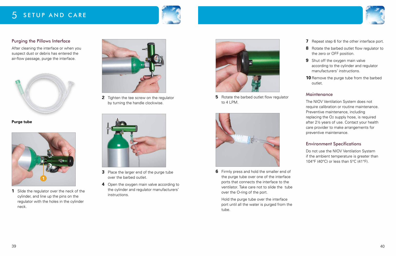
Purging the Pillows Interface
Aftercleaningtheinterfaceorwhenyoususpect dust or debris has entered the air-flow passage, purge the interface.
Purge tube
1 Slide the regulator over the neck of the cylinder, and line up the pins on the regulator with the holes in the cylinder neck.
2 Tighten the tee screw on the regulator by turning the handle clockwise.
3 Place the larger end of the purge tube over the barbed outlet.
4 Open the oxygen main valve according to the cylinder and regulator manufacturers’ instructions.
5 Rotate the barbed outlet flow regulator to 4 LPM.
6 Firmly press and hold the smaller end of the purge tube over one of the interface ports that connects the interface to the ventilator. Take care not to slide the tube over the O-ring of the port.
Hold the purge tube over the interface port until all the water is purged from the tube.
7 Repeat step 6 for the other interface port.
8 Rotate the barbed outlet flow regulator to the zero or OFF position.
9 Shut off the oxygen main valve according to the cylinder and regulator manufacturers’ instructions.
10 Remove the purge tube from the barbed outlet.
maintenance
The NIOV Ventilation System does not require calibration or routine maintenance. Preventive maintenance, including replacing the O2 supply hose, is required after2½yearsofuse.Contactyourhealthcare provider to make arrangements for preventive maintenance.
environment Specifications
DonotusetheNIOVVentilationSystemif the ambient temperature is greater than 104°F(40°C)orlessthan5°C(41°F).
4241
5 s e t u p a n d c a r e
BATTeRY ReTRAININg AND RePlACemeNT
Battery Retraining
Afterabatteryhasbeenchargednumeroustimes, the battery charge icon may not accurately display the battery charge.
For example, after fully charging the battery, the battery charge icon may only display 3 bars instead of 4. In this case, the battery has more charge than the battery charge icon indicates. Or, the battery charge icon may display 2 bars when the charge is really only 1. In this case, the battery has less charge than the battery icon indicates. If you notice that the battery seems to last longer or shorter than the battery charge icon suggests, you may need to “retrain” the battery so the icon more accurately displays the battery charge.
Retraining the battery involves discharging it fully and then recharging it fully until the battery icon on the touch screen accurately reflects a full charge and no charge.
To retrain a battery follow these steps:
1 Turn on the ventilator, press an Activity button, and let the battery discharge fully until the ventilator shuts itself off.
2 Confirmtheventilatorisoff.Connectthe wall battery charger to the ventilator. Confirmthatthechargerlightisred.
3 Let the ventilator charge until the charger light turns green.
4 Turntheventilatoron.Checkthatthebattery charge icon displays four white bars . If it does not, repeat steps 2 - 4.
Note: You will encounter a System Fault alarm after turning on the ventilator once the battery is fully discharged and recharged again. Press OK on the alarm display screen to allow the ventilator to reboot.
If after repeating steps 2 - 4 a second time, the ventilator still does not show four white bars, contact your health care provider.
Battery Replacement
The internal ventilator battery is not serviced in the field. It should be replaced every 2.5 years or when runtime degrades to an unacceptablelevel.ContactyourBreatheTechnologies service provider to make arrangements for replacing the battery.
oxYgeN SUPPlY INFoRmATIoN
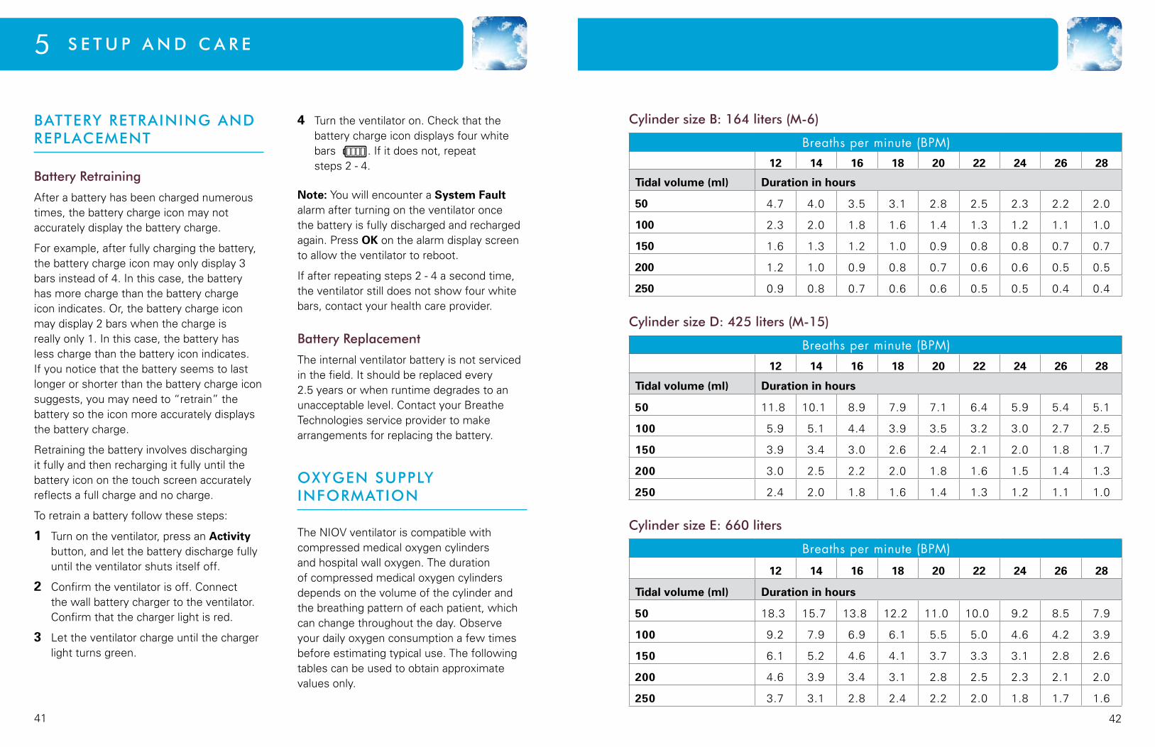
The NIOV ventilator is compatible with compressed medical oxygen cylinders and hospital wall oxygen. The duration of compressed medical oxygen cylinders depends on the volume of the cylinder and the breathing pattern of each patient, which can change throughout the day. Observe your daily oxygen consumption a few times before estimating typical use. The following tables can be used to obtain approximate values only.
Cylinder size B: 164 liters (m-6)
Breaths per minute (BPM) 12 14 16 18 20 22 24 26 28
Tidal volume (ml) Duration in hours
50 4.7 4.0 3.5 3.1 2.8 2.5 2.3 2.2 2.0
100 2.3 2.0 1.8 1.6 1.4 1.3 1.2 1.1 1.0
150 1.6 1.3 1.2 1.0 0.9 0.8 0.8 0.7 0.7
200 1.2 1.0 0.9 0.8 0.7 0.6 0.6 0.5 0.5
250 0.9 0.8 0.7 0.6 0.6 0.5 0.5 0.4 0.4
Cylinder size D: 425 liters (m-15)
Breaths per minute (BPM) 12 14 16 18 20 22 24 26 28
Tidal volume (ml) Duration in hours
50 11.8 10.1 8.9 7.9 7.1 6.4 5.9 5.4 5.1
100 5.9 5.1 4.4 3.9 3.5 3.2 3.0 2.7 2.5
150 3.9 3.4 3.0 2.6 2.4 2.1 2.0 1.8 1.7
200 3.0 2.5 2.2 2.0 1.8 1.6 1.5 1.4 1.3
250 2.4 2.0 1.8 1.6 1.4 1.3 1.2 1.1 1.0
Cylinder size e: 660 liters
Breaths per minute (BPM)
12 14 16 18 20 22 24 26 28
Tidal volume (ml) Duration in hours
50 18.3 15.7 13.8 12.2 11.0 10.0 9.2 8.5 7.9
100 9.2 7.9 6.9 6.1 5.5 5.0 4.6 4.2 3.9
150 6.1 5.2 4.6 4.1 3.7 3.3 3.1 2.8 2.6
200 4.6 3.9 3.4 3.1 2.8 2.5 2.3 2.1 2.0
250 3.7 3.1 2.8 2.4 2.2 2.0 1.8 1.7 1.6
4443
I C o N S6Chapter
Ventilator Ventilator power on/off button.
Ventilator Indicates communication port. This port is only
used by the manufacturer.
Ventilator Orientation marker for power-in port.
Ventilator and Product label
Indicates direct current and denotes the location where the battery charger is plugged into the ventilator.
Ventilator Ontheventilator,theAlarmSilencebuttonturnsoff vibrator or audible alarm.
Touch screen DisplayedintheActiveAlarmswindowofthetouch screen if an active alarm has not been silenced.
Touch screen DisplayedintheActiveAlarmswindowofthetouch screen if an active alarm has been silenced. Displayedonthebottomofeachventilatorscreenif all active alarms have been silenced.
Touch screen Displayedoneachventilatorscreenifbatterystatus is unknown or charge is critically low.
Touch screen Displayedoneachventilatorscreenifbatteryhasapproximately 1/6 of its charge remaining.
Touch screen Displayedoneachventilatorscreenifbatteryhasapproximately ¼ of its charge remaining.
Touch screen Displayedoneachventilatorscreenifbatteryhasapproximately ½ of its charge remaining.
Ventilator, touch screen
Onventilator,LowActivitybuttondeliversaugmentation volume at rate set by clinician in ventilatorClinician’sSettingsmenu. DisplayedontheVolumeSettingsscreenasalabelfortheLowActivityaugmentationvaluesetby clinician. Displayedoneachventilatorscreenifaugmentation volume delivery is set to Low Activity.
Ventilator, touch screen
Onventilator,MediumActivitybuttondeliversaugmentation volume at rate set by clinician in ventilatorClinician’sSettingsmenu. DisplayedontheVolumeSettingsscreenasalabelfortheMediumActivityaugmentationvalueset by clinician. Displayedoneachventilatorscreenifaugmentation volume delivery is set to Medium Activity.
Ventilator, touch screen
Onventilator,HighActivitybuttondeliversaugmentation volume at rate set by clinician in ventilatorClinician’sSettings. DisplayedontheVolumeSettingsscreenasalabelfortheHighActivityaugmentationvaluesetby clinician. Displayedoneachventilatorscreenifaugmentation volume delivery is set to High Activity.
Icon Where used Meaning
Icon Where used Meaning

4645
Product label Indicates product is a Bluetooth wireless compatible devise that emits radio frequency waves.
Product label Indicates disposal of device must conform to WasteinElectricalandElectronicEquipmentDirective2002/96/EC.
Product label Indicates manufacturer and denotes the location of the manufacturer name, address.
Product label Indicates date of manufacture.
O2 Product label Indicates oxygen and denotes the location where the oxygen hose attaches to the ventilator.
Product label Indicates catalog number and denotes the location of the part number for the device.
Product label Indicates serial number and denotes the location of the serial number for the device.
Product label Indicates product meets US standards for use with medical electrical equipment.
Battery charger label On battery charger indicates indoor use only and denotes that it should only be used indoors.
Battery charger label On battery charger indicates battery charge. The black shaded area represents the amount of charge within the battery (here shown with ~80% charge).
Battery charger label On battery charger indicates battery charger meets European economic area standards for use with medical electrical equipment and information technology equipment.
Touch screen Displayedoneachventilatorscreenifbatteryhasapproximately ¾ of its charge remaining.
Touch screen Displayedoneachventilatorscreenifbatterycharge is approximately full.
Touch screen Displayedoneachventilatorscreenifbatteryischarging.
Touch screen Displayedoneachventilatorscreen.TouchingtheWrenchbuttondisplaystheMenuscreen.
Touch screen Displayedoneachventilatorscreen.TouchingtheFlip button rotates the touch screen 180°.
Touch screen Displayedoneachventilatorscreeniftheventilator is in vibrate mode.
Product label IndicatesBFtypeequipment.Deviceisolatesthepatient from any live voltage in the equipment.
IPX1 Product label Indicates device is protected against dripping water.
Product label IndicatesaclassIIdevice.Deviceisdoubleinsulated and does not require a safety connection to electrical earth (US: ground).
Product label and documentation
On product indicates accompanying documentation includes important information that must be read before using device.
Product label Indicates product emits non-ionizing radiation.
6 I C o N S
Icon Where used Meaning Icon Where used Meaning

4847
I n d e xI N D e x
interfacechecking position ___________________18cleaning ___________________________38connecting to ventilator ______________16length of use _______________________38wearing ____________________________17purging ____________________________38
m
maintenanceof ventilation system ________________40
menu screen _________________________10
o
oxygen regulatorconnecting to oxygen cylinder ________14
oxygen supplycompatible cylinders with ventilator ____5connecting and turning on ____________13duration of cylinders _________________42flow rate display _____________________9no volume output _______________ 29, 30regulating pressure of _______________13replacing cylinders __________________15shorter than expected duration _______29
oxygen supply hosewhen to disconnect _____________ 13, 15
P
patient participationrequired for ventilator use _____________2
S
safety information ____________________3
screen brightnessadjusting ___________________________36
settings menuaccessing __________________________32
setup and care _______________________31
software version information _________37
symbols and conventions warnings, cautions and tips ____________2
A
activity settings and buttonsbuttons and icons representing _________6choosing or changing a setting ________19
alarmsactive alarms window _______________24additional alarm troubleshooting ______28alarm checks _______________________38alarm message display _______________23backup alarm buzzer __________________6high-priority alarms __________________26low-priority alarms __________________28medium-priority alarms ______________26silencing and clearing ________________25sounds and priority levels ____________23
audiosetting loudness ____________________35
augmentation volumeicons representing ___________________9corresponding to activity settings _____19
B
batteryassemble and charge ________________12check the battery charge _____________12icons representing charge ________ 12, 44low charge alarm ____________________28troubleshooting charge duration ___ 30, 41very low charge alarm _______________27
battery chargerassembling _________________________12
belt clipattaching to ventilator ________________19
breath ratedisplayed on Home screen ____________9high breath rate alarm _______________26low breath rate alarm ________________27
C
cleaningcleaning the interface ________________38cleaning the ventilator _______________38purging the interface ________________38
clinical considerations for use __________2
compliance and IEC classification _____66
h
home screen __________________________8
I
icons ________________________________43
5049
I n d e x I n d e x
T
time and datesetting _____________________________33
touch screenenergy-save mode __________________10features ____________________________9
trigger sensitivityadjusting ___________________________20
troubleshooting alarms ____________ 2, 26
troubleshooting situations ____________28
U
utilitesmenu ______________________________32
V
ventilation systemcaring for __________________________37daily alarm checks ___________________38daily visual checks __________________37environment specifications ___________40system components __________________5
ventilatoradjustingscreenbrightness __________36adjustingtriggersensitivity ___________20caring for __________________________37changing settings ___________________32 choosing an activity setting ___________19cleaning ___________________________38connecting to oxygen cylinder ________14features ____________________________6home screen ________________________8icons ______________________________43menu screen _______________________10system overview _____________________4touch screen energy-save mode ______10touch screen features ________________9turning on and off ____________________8
vibration modesetting _____________________________34
W
warranty _____________________________ i
Inside Back Cover