THE BRAND PLUMBERS TRUST - Elson · 2019. 11. 27. · and installation manual COPPER & BRASS...
32
Quality ISO 9001 Certificate No. QEC27227 Product information and installation manual COPPER & BRASS FITTINGS (GAS) THE BRAND PLUMBERS TRUST Version 4.0 Lead Free Brass Certificate No. SMK 26127 Standard AS 3688 Certified Product Australian Standard Certificate No. SMK 02497 Standard AS 3688 Certified Product Australian Standard
Transcript of THE BRAND PLUMBERS TRUST - Elson · 2019. 11. 27. · and installation manual COPPER & BRASS...

Quality ISO 9001
Certificate No. QEC27227
Product information and installation manual
COPPER & BRASS FITTINGS(GAS)
THE BRANDPLUMBERS TRUST
Version 4.0
Lead Free Brass
Certificate No. SMK 26127Standard AS 3688
Certi
fied
Prod
uct
AustralianStandard
Certificate No. SMK 02497Standard AS 3688
Certi
fied
Prod
uct
AustralianStandard

PRESS
Contents:ELSON PRESS INTRODUCTION 2ELSON PRESS FEATURES 3ELSON PRESS KEY BENEFITS 3ELSON PRESS GAS COPPER PRESS FITTING INFORMATION 4ELSON PRESS WARRANTY 5ELSON PRESS GAS TECHNICAL DATA 6ELSON PRESS DESIGN CONSIDERATIONS 7ELSON PRESS GAS INSTALLATION GUIDE 8ELSON PRESS GAS FAQs 10ELSON PRESS GAS PRODUCT LISTING 12ELSON PRESS GAS BALL VALVES 19ELSON PRESS TOOLS 19ELSON PRESS GAS PRODUCT DIMENSIONS 21STANDARDSMARK LICENCE CERTIFICATE 30
Elson Australasia is proud to introduce the ELSON Press range of copper and brass press fittings to suit AS 1432 Copper Tube. Elson is the manufacturer and wholesale supplier of quality plumbing products specifically designed for the Australian market since 1993 and ISO 9001 accredited through SAI Global.At Elson we’re passionate about quality and offering the best design features on the market. ELSON Press is the result of years of in-house and third-party testing processes and raw material formulation to ensure the finest quality range of copper tube press fittings.Elson’s manufacturing portfolio includes a complete range of COPPER & BRASS PRESS fittings, BRASSWARE, TAPWARE and water & gas jointing systems, all of which are fully approved to the required Australian and/or New Zealand Standards.ELSON Press fittings are supported nationally by our sales and service team of professionals that are equipped to train and service Plumbers, Gas Fitters, Plumbing Merchants and Consultants.ELSON Press fittings offer three specific system applications:• Water – fittings with black EPDM O-rings.• Gas – fittings with yellow HBNR O-rings.• High Temperature / Solar – fittings with red FKM O-rings.ALL fittings are manufactured from high quality, batch tested, ultra low lead DR Brass or Copper in sizes 15-100mm. All fittings 15-50mm include leak before press O-ring technology.ELSON Press fittings are manufactured to comply with Australian Standard AS 3688 certified by SAI Global and comply with AS/NZS 4020 for Water and AS/NZS 5601 for Gas. Certificate for brass press gas fittings is SMK 02497. Certificate for copper press gas fittings is SMK 26127.

ELSON Press Gas is a comprehensive brass and copper press fitting system for use with conformant copper tube to AS 1432 Type A and B Only: providing a durable and secure leak-proof joint for many gas Applications. (Other Applications are possible based on requirements by consultation with Elson).
ELSON Press Gas fittings are Standardmark Certified(Certificate Number SMK 26127 for copper gas fittings, SMK 02497 for brass gas fittings) and manufactured in accordance to AS 3688.
Lead Free Brass
Reduced Installation TimeSimple, quick and reliable installation translates to reduced labour time.
Flame Free Flame free installation means no need for hot works permits and no need to lug around heavy bottles used for brazing.
Long Lasting Performance When installed correctly as per the requirements of this document and other regulatory requirements.
Fully Certified and TestedExtensive third party certification and testing offers peace of mind, in addition warranty and insurance is covered by Elson.
Secure Joint Secure and durable permanent joint ensures the fitting can not be tampered with.
Leak Detection Design features on the O-ring allows for missed press leak detection when tested correctly using the defined procedure in this manual.
● “V” Profle Press Pattern
● “Leak Before Press” O-ring
● 15mm - 100mm Water & Gas
● Adapt directly to BUSHPEX
● Hi - Temp Fittings
Key Benefits
Features● Novopress Tool for BUSHPEX & ELSON Press
● All Brass Press fittings are made of Lead Free DR Brass

PRESS
4 | ELSON Press Gas TECHNICAL AND INSTALLATION MANUAL
Applications ELSON Press Gas Fittings are suitable for:• Natural gas installations• Liquid Petroleum Gas installations• Other gas installations (see table page 6)• Other media also possible (with consultation on application to Elson for approval)
Leak Before Press The precise design of ELSON Press fittings allows air to pass the sealing element of unpressed fittings, thereby providing a leakage point during the commissioning of the system. When the fitting is pressed, the O-ring material compresses, filling the gaps, creating a leak free joint.Final testing of the system should be conducted in accordance with AS/NZS5601 and any other additional local regulations and/or requirements.
IMPORTANT: Unpressed fittings are identified by pressurising the system slowly with air, increase the pressure to be between 50 kPa and 200 kPa. Inspect each joint with a leak check liquid material/spray for any visual signs of leakage. After conformance, conduct testing as per AS/NZS5601.
ELSON Press Fittings Information
Testing with Air
ELSON PressDN20
ELSON PressDN100
GAS
GAS

PRESS
Warranty on ELSON Press Fittings Elson as the manufacturer and wholesale supplier of quality plumbing products is passionate about quality, customer service and product support. Elson recognises the importance of providing the support, confidence and peace of mind for licenced installers to use ELSON Press fittings.Accordingly, Elson will provide the same warranty on ELSON Press fittings as the copper tube used on the installation to a maximum of 25 years. Please note that if the warranty on the copper tube is 10 years then the ELSON Press fitting Warranty will also be 10 years. Our warranty applies to fault or defect in the ELSON Press fittings only and does not cover fault arising from the external environment or caused by incorrect installation.In addition to this the warranty will only cover ELSON Press fittings installed by a Licenced Plumber or Gas Fitter in accordance with this TECHNICAL AND INSTALLATION GUIDE and AS/NZS 3500 for water and AS/NZS 5601 for Gas and any other local regulations and/or requirements. The warranty only applies to installation with AS 1432 type A or type B conformant copper tube. All copper press tools MUST be kept fully functional and in proper working order as any leak resulting from incorrect pressing does not relate to and will therefore not be covered by this product warranty. Approved tooling and correct installation as outlined in this manual must be used.
Tooling Repair and ServicingElson repairs and services Novopress battery tools at our National Distribution Centre in Minchinbury NSW. Please contact your local ELSON Press stockist. You can also contact Elson National Distribution Centre or your regional sales manager for any repair or service enquiries.
UP TO 25 YEARS WARRANTY
ELSON Press Gas TECHNICAL AND INSTALLATION MANUAL | 5

PRESS
6 | ELSON Press Gas TECHNICAL AND INSTALLATION MANUAL
Technical Data/Applications (Gas)ELSON Press is suitable for use with type A and B copper tube complying with AS 1432.
Note: AS3688 covers Mechanical Joint Press fittings for GAS to 500Kpa at 70 Degrees Celcius, with fittings exposed to direct sunlight being able to support temperature up to 100 Degrees Celcius for intermittent periods.
ELSON Press GAS HNBR O-ring have been tested up to 100 Degrees Celcius.
GAS O-RING SCOPE OF APPLICATIONApplication Comment MOP
[kPa]TEMP [ºC]
Gas (HNBR)
Natural Gas/LPGNatural Gas Australian gas approved,
Note: The scope of AS/NZS5601 for all gas systems is restricted to 200kPa
200 70
ü
Liquid Petroleum Gasü
Not Suitable:Acetylene, Ammoniac gases, Coolant Inhibitor, Glycerine Triacetate, Medical Gas Applications, Methanol, Refrigeration and Air Conditioning Applications, Sodium Hydroxide, Urea Solution.
MOP[kPa] Maximum safe working pressure (continuous operating pressure), greater short duration peaks possible
TEMP(ºC) Maximum continuous operating temperature (Celsius), greater short duration peaks possibleHNBR Hydrogenated Nitrile Butadiene Rubber
Other media can be used subject to request on application with Elson.
Other tooling with compatible jaws may be approved on application to Elson. Written approval is required from Elson before use on ELSON Press Product.
APPROVED TOOLS (with compliant copper press jaws)Manufacturer Model/s Approved
Novopress ACO 152, ACO 203 ü
Milwaukee M12HPT-0, M128HPT-0 ü
Viega Picco, PT3-AH, 4B ü
Rothenberger Romax Compact, Romax 3000 ü
Ridgid RP340 & RP210-B ü
Kempress KPS, KPL & KPL2 ü
PRESS
ELSON Press Gas TECHNICAL AND INSTALLATION MANUAL | 7
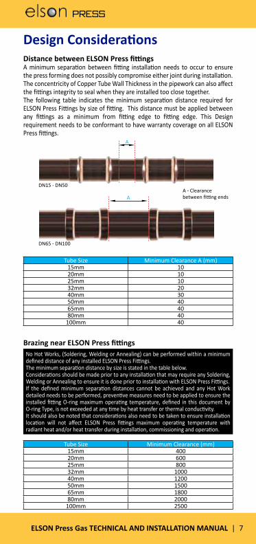
Design Considerations Distance between ELSON Press fittingsA minimum separation between fitting installation needs to occur to ensure the press forming does not possibly compromise either joint during installation. The concentricity of Copper Tube Wall Thickness in the pipework can also affect the fittings integrity to seal when they are installed too close together. The following table indicates the minimum separation distance required for ELSON Press Fittings by size of fitting. This distance must be applied between any fittings as a minimum from fitting edge to fitting edge. This Design requirement needs to be conformant to have warranty coverage on all ELSON Press fittings.
Brazing near ELSON Press fittings
Tube Size Minimum Clearance A (mm)15mm 1020mm 1025mm 1032mm 2040mm 3050mm 4065mm 4080mm 40
100mm 40
Tube Size Minimum Clearance (mm)15mm 40020mm 60025mm 80032mm 100040mm 120050mm 150065mm 180080mm 2000
100mm 2500
No Hot Works, (Soldering, Welding or Annealing) can be performed within a minimum defined distance of any installed ELSON Press Fittings.The minimum separation distance by size is stated in the table below.Considerations should be made prior to any installation that may require any Soldering, Welding or Annealing to ensure it is done prior to installation with ELSON Press Fittings.If the defined minimum separation distances cannot be achieved and any Hot Work detailed needs to be performed, preventive measures need to be applied to ensure the installed fitting O-ring maximum operating temperature, defined in this document by O-ring Type, is not exceeded at any time by heat transfer or thermal conductivity.It should also be noted that considerations also need to be taken to ensure installation location will not affect ELSON Press fittings maximum operating temperature with radiant heat and/or heat transfer during installation, commissioning and operation.
A
AA - Clearance between fitting ends
DN15 - DN50
DN65 - DN100

PRESS
8 | ELSON Press Gas TECHNICAL AND INSTALLATION MANUAL
Table Insertion Marking Depth by SizeTube Size Marking Insertion Depth
DN15 19mmDN20 24mmDN25 25mmDN32 27mmDN40 34mmDN50 42mmDN65 45mmDN80 52mm
DN100 62mm
Installation Instructions
2. Remove Burrs Make sure that the internal and external tube end is completely free from burrs or sharp edges by using a file or deburring tool. Note: ensure over use does not affect the tube end outside diameter.
3. Inspect the FittingBefore inserting the tube, check O-rings (1-50mm) and also spacers/grab rings (65-100mm) for correct placement, they are free of damage or any dust, dirt or debris. We recommend the fittings are retained in packaging up to the point of use where ever possible.
4. Marking Insertion Depth on TubeAll cut and deburred Copper tube ends for insertion into the fitting require an insertion depth mark to be applied to the tube prior to insertion into the fitting. The mark will be applied by measuring from the end of the tube with a ruler or tape measure and using a marker pen to the required length. The mark will ensure the tube is inserted completely into the fitting prior to press.
1. Cut the Tube An appropriate copper tube cutter must be used to ensure a clean square cut. Note: It is important that the copper tube is cut completely square, the end of the tube (outside) must be clean and free from any scratches or damage such as dints or deformity.
Note: Check pipe and fitting compatibility; both the piping material (must be type A or B copper tube conformant to AS 1432) and the O-ring must be checked if suitable for purpose (see page 6) and the exterior environment must also be considered.
PRESS
ELSON Press Gas TECHNICAL AND INSTALLATION MANUAL | 9
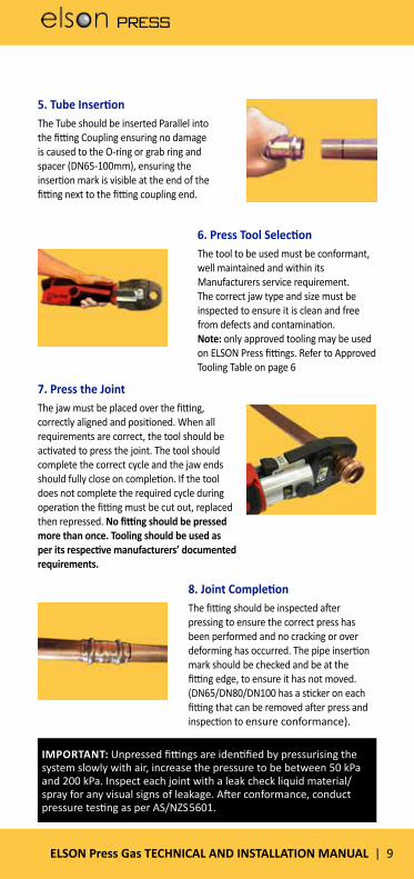
6. Press Tool SelectionThe tool to be used must be conformant, well maintained and within its Manufacturers service requirement. The correct jaw type and size must be inspected to ensure it is clean and free from defects and contamination. Note: only approved tooling may be used on ELSON Press fittings. Refer to Approved Tooling Table on page 6
7. Press the JointThe jaw must be placed over the fitting, correctly aligned and positioned. When all requirements are correct, the tool should be activated to press the joint. The tool should complete the correct cycle and the jaw ends should fully close on completion. If the tool does not complete the required cycle during operation the fitting must be cut out, replaced then repressed. No fitting should be pressed more than once. Tooling should be used as per its respective manufacturers’ documented requirements.
8. Joint CompletionThe fitting should be inspected after pressing to ensure the correct press has been performed and no cracking or over deforming has occurred. The pipe insertion mark should be checked and be at the fitting edge, to ensure it has not moved. (DN65/DN80/DN100 has a sticker on each fitting that can be removed after press and inspection to ensure conformance).
5. Tube InsertionThe Tube should be inserted Parallel into the fitting Coupling ensuring no damage is caused to the O-ring or grab ring and spacer (DN65-100mm), ensuring the insertion mark is visible at the end of the fitting next to the fitting coupling end.
IMPORTANT: Unpressed fittings are identified by pressurising the system slowly with air, increase the pressure to be between 50 kPa and 200 kPa. Inspect each joint with a leak check liquid material/spray for any visual signs of leakage. After conformance, conduct pressure testing as per AS/NZS 5601.

PRESS
10 | ELSON Press Gas TECHNICAL AND INSTALLATION MANUAL
ELSON Press Fittings FAQELSON Press Fittings Frequently Asked Questions Q. Do I need to lubricate the O-ring?A. No, the O-ring is pre-lubricated. Using additional
lubricants could reduce the longevity of the O-ring and void the warranty. Care should be taken during copper tube insertion to ensure the O-ring does not roll or dislodge.
Q. What grades/types of copper tube do the fittings suit?A. Annealed (ANN), Bendable Quality (BQ) and Hard
Drawn (HD) Type A and B copper tube compliant to AS1432.
Q. What pipe preparation is required?A. Please see ‘Installation Instructions’ on pages 8 & 9.
Q. When using ELSON Press with older pipes, what surface preparation is required?
A. The surface should be prepared in the same way as you normally would with brand new pipe.
Q. Can ELSON Press Fittings be placed in the ground?A. Yes, but the tube and fittings must be protected when
installed in any corrosive and/or acidic environments, this includes possible ground water exposure, as per regulatory requirements.
Q. Can ELSON Press Fittings be exposed to direct UV sunlight and heat?
A. Yes. Please refer to the Table on page 6.
Q. Can ELSON Press Fittings be used with medical gases?A. No, the fittings are not recommended for use with
most medical gases. Consultation with Elson on specific installation requirements is recommended.

PRESS
ELSON Press Gas TECHNICAL AND INSTALLATION MANUAL | 11
ELSON Press Fittings Frequently Asked Questions Q. Am I able to use other tools to crimp a ELSON Press fitting?A. Yes, ELSON Press fittings use a V profile and are therefore
compatible with the following tools and jaws that use the same profile: Novopress ACO 152/203, Milwaukee (M12HPT-0, M128HPT-0), Kempress tools (KPS, KPL & KPL2), Viega (Picco), Viega (PT3-AH & 4B), Rothenberger (Romax compact), Rothenberger (Romax 3000), Ridgid (RP340, RP210-B), hydraulic press tools.
Q. Does the clipping of fittings/tube differ from a welded copper application?
A. No, the same type of clips can be used when installed in accordance with Australian standards and any other local regulatory requirements.
Q. What is the recommended space between pressed fittings?
A. Please see the ‘distance between ELSON Press fittings’ section on page 7.
Q. Can ELSON Press fittings be dismantled and reused?A. No, once pressed it is a permanent installation.
Q. Will I be able to rotate a ELSON Press fitting once installed?A. No, once pressed, a ELSON Press fitting cannot be
rotated.
Q. Can you braze (silver solder) near a ELSON Press fitting?A. See section on ‘Brazing near ELSON Press fittings’ on
page 7. It is not recommended unless distance and precautionary measures are taken to prevent damage to the sealing O-ring.
Q. What procedure should I follow to show any leaks at the end of my installation?
A. Refer to ‘Testing with Air’ on page 4 of this Technical and Installation Guide.
Q. What are some of the benefits of ELSON Press fittings?A. Fast, easy and ergonomical installation. The built in
ELSON Press Leak indicator design gives an indication of an unpressed joint (refer to instructions on page 4), which will help uncover possible problems with installation.

PRESS
12 | ELSON Press Gas TECHNICAL AND INSTALLATION MANUAL
PRODUCT LISTING
PRESS

PRESS
ELSON Press Gas TECHNICAL AND INSTALLATION MANUAL | 13
No 1 CouplingCode Size (D1)
35000 DN15
35004 DN20
35006 DN25
35008 DN32
35010 DN40
35012 DN50
35014 DN65
35016 DN80
35018 DN100
No 1S Slip CouplingCode Size (D1)
35080 DN15
35082 DN20
35084 DN25
35086 DN32
35088 DN40
35090 DN50
35092 DN65
35094 DN80
35096 DN100
No 1R Red CouplingCode Size (D1) X (D2)
35024 DN 20 X 15 No 1R
35026 DN 25 X 15 No 1R
35028 DN 25 X 20 No 1R
35034 DN 32 X 25 No 1R
35038 DN 40 X 25 No 1R
35040 DN 40 X 32 No 1R
35044 DN 50 X 25 No 1R
35046 DN 50 X 32 No 1R
35048 DN 50 X 40 No 1R
35050 DN 65 X 32 No 1R
35051 DN 65 X 40 No 1R
35052 DN 65 X 50 No 1R
35053 DN 80 X 40 No 1R
35054 DN 80 X 50 No 1R
35055 DN 80 X 65 No 1R
35056 DN 100 X 50 No 1R
35057 DN 100 X 65 No 1R
35058 DN 100 X 80 No 1R
ELSON Press Gas Fittings
PRESS
14 | ELSON Press Gas TECHNICAL AND INSTALLATION MANUAL
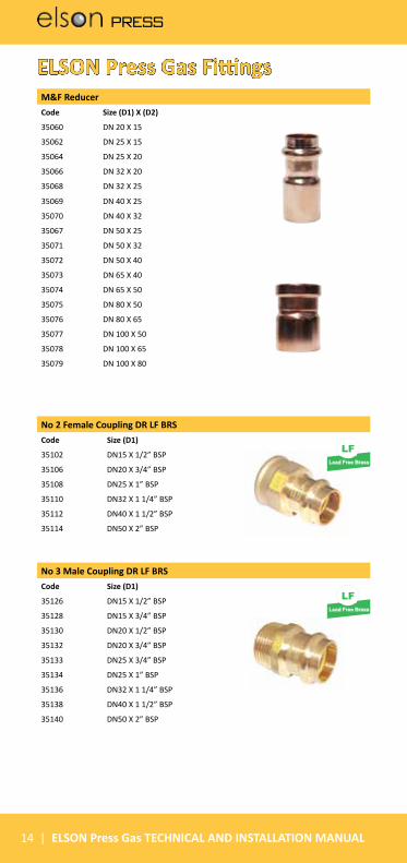
No 3 Male Coupling DR LF BRSCode Size (D1)
35126 DN15 X 1/2” BSP
35128 DN15 X 3/4” BSP
35130 DN20 X 1/2” BSP
35132 DN20 X 3/4” BSP
35133 DN25 X 3/4” BSP
35134 DN25 X 1” BSP
35136 DN32 X 1 1/4” BSP
35138 DN40 X 1 1/2” BSP
35140 DN50 X 2” BSP
No 2 Female Coupling DR LF BRSCode Size (D1)
35102 DN15 X 1/2” BSP
35106 DN20 X 3/4” BSP
35108 DN25 X 1” BSP
35110 DN32 X 1 1/4” BSP
35112 DN40 X 1 1/2” BSP
35114 DN50 X 2” BSP
M&F ReducerCode Size (D1) X (D2)
35060 DN 20 X 15
35062 DN 25 X 15
35064 DN 25 X 20
35066 DN 32 X 20
35068 DN 32 X 25
35069 DN 40 X 25
35070 DN 40 X 32
35067 DN 50 X 25
35071 DN 50 X 32
35072 DN 50 X 40
35073 DN 65 X 40
35074 DN 65 X 50
35075 DN 80 X 50
35076 DN 80 X 65
35077 DN 100 X 50
35078 DN 100 X 65
35079 DN 100 X 80
ELSON Press Gas Fittings
Lead Free Brass
Lead Free Brass

PRESS
ELSON Press Gas TECHNICAL AND INSTALLATION MANUAL | 15
No 12 90D Elbow F&FCode Size (D1)
35152 DN15
35156 DN20
35158 DN25
35160 DN32
35162 DN40
35164 DN50
35166 DN65
35168 DN80
35170 DN100
No 12 45D Elbow F&FCode Size (D1)
35329 DN15
35331 DN20
35328 DN25
35330 DN32
35332 DN40
35334 DN50
35336 DN65
35338 DN80
35340 DN100
No 12 90D Elbow M&FCode Size (D1)
35176 DN15
35178 DN20
35180 DN25
35182 DN32
35184 DN40
35186 DN50
35188 DN65
35190 DN80
35192 DN100
No 12 45D Elbow M&FCode Size (D1)
35342 DN15
35344 DN20
35346 DN25
35348 DN32
35350 DN40
35352 DN50
35354 DN65
35356 DN80
35358 DN100
ELSON Press Gas Fittings

PRESS
16 | ELSON Press Gas TECHNICAL AND INSTALLATION MANUAL
No 13 Male Elbow DR LF BRSCode Size (D1)
3543035432
DN16 X 1/2”DN20 X 3/4”
No 14 Female Elbow DR LF BRSCode Size (D1)
35444 DN20 X 3/4”
No 15 Female Back Plate Elbow DR LF BRSCode Size (D1)
35364 DN15 X 1/2”
35366 DN20 X 3/4”
No 19 Male Back Plate Elbow DR LF BRSCode Size (D1)
35378 DN15 X 1/2” X 75MM long
35380 DN15 X 1/2” X 95MM long
ELSON Press Gas Fittings
No 24 Tee Equal
Code Size (D1)
35246 DN15
35250 DN20
35252 DN25
35254 DN32
35256 DN40
35258 DN50
35260 DN65
35262 DN80
35264 DN100
Lead Free Brass
Lead Free Brass
Lead Free Brass
Lead Free Brass
PRESS
ELSON Press Gas TECHNICAL AND INSTALLATION MANUAL | 17
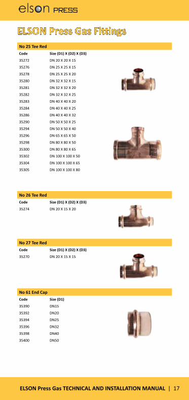
No 26 Tee RedCode Size (D1) X (D2) X (D3)
35274 DN 20 X 15 X 20
No 27 Tee RedCode Size (D1) X (D2) X (D3)
35270 DN 20 X 15 X 15
No 25 Tee RedCode Size (D1) X (D2) X (D3)
35272 DN 20 X 20 X 15
35276 DN 25 X 25 X 15
35278 DN 25 X 25 X 20
35280 DN 32 X 32 X 15
35281 DN 32 X 32 X 20
35282 DN 32 X 32 X 25
35283 DN 40 X 40 X 20
35284 DN 40 X 40 X 25
35286 DN 40 X 40 X 32
35290 DN 50 X 50 X 25
35294 DN 50 X 50 X 40
35296 DN 65 X 65 X 50
35298 DN 80 X 80 X 50
35300 DN 80 X 80 X 65
35302 DN 100 X 100 X 50
35304 DN 100 X 100 X 65
35305 DN 100 X 100 X 80
ELSON Press Gas Fittings
No 61 End CapCode Size (D1)
35390 DN15
35392 DN20
35394 DN25
35396 DN32
35398 DN40
35400 DN50
PRESS
18 | ELSON Press Gas TECHNICAL AND INSTALLATION MANUAL
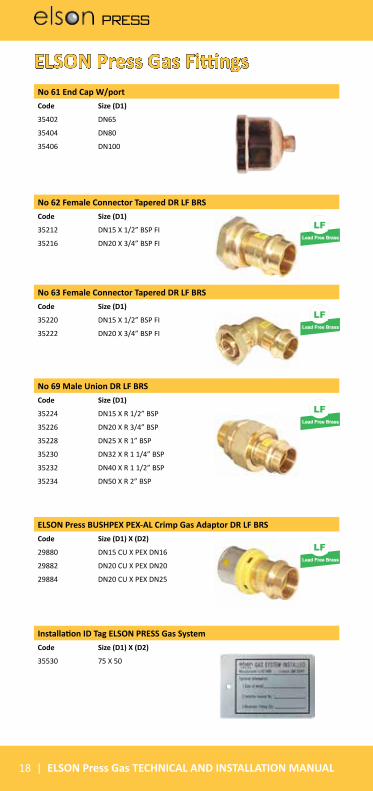
No 61 End Cap W/portCode Size (D1)
35402 DN65
35404 DN80
35406 DN100
No 62 Female Connector Tapered DR LF BRSCode Size (D1)
35212 DN15 X 1/2” BSP FI
35216 DN20 X 3/4” BSP FI
No 63 Female Connector Tapered DR LF BRSCode Size (D1)
35220 DN15 X 1/2” BSP FI
35222 DN20 X 3/4” BSP FI
No 69 Male Union DR LF BRSCode Size (D1)
35224 DN15 X R 1/2” BSP
35226 DN20 X R 3/4” BSP
35228 DN25 X R 1” BSP
35230 DN32 X R 1 1/4” BSP
35232 DN40 X R 1 1/2” BSP
35234 DN50 X R 2” BSP
ELSON Press Gas Fittings
ELSON Press BUSHPEX PEX-AL Crimp Gas Adaptor DR LF BRSCode Size (D1) X (D2)
29880 DN15 CU X PEX DN16
29882 DN20 CU X PEX DN20
29884 DN20 CU X PEX DN25
Installation ID Tag ELSON PRESS Gas SystemCode Size (D1) X (D2)
35530 75 X 50
Lead Free Brass
Lead Free Brass
Lead Free Brass
Lead Free Brass

PRESS
ELSON Press Gas TECHNICAL AND INSTALLATION MANUAL | 19
elson PRESS Gas Ball Valve DR LF BRS L/H Code Size (D1)
73580 DN15
73582 DN20
73584 DN25
73586 DN32
73588 DN40
73590 DN50
NOVOPRESS ACO-152 TOOL DN15-DN32 IN CASE W/2 BATTERIES & CHARGERCode Size (D1)
36800 DN15-DN32
NOVOPRESS ACO-203BT TOOL DN15-DN32 JAWS, 2 BATS & 1CHGRCode Size (D1)
36905 DN15-DN32
NOVOPRESS PRESS JAW SET DN40-DN50 SUIT ACO-203BT Code Size (D1)
36906 DN40-DN50
ELSON Press Gas Ball Valves
ELSON Press Tools
elson PRESS Gas Ball Valve DR LF BRS L/H Code Size (D1) X (D2)
73560 DN15 X Rp 1/2
73562 DN20 X Rp 3/4
Lead Free Brass
Lead Free Brass
AGA 8350AS 4617
TMAGA
R
AGA 8350AS 4617
TMAGA
R

PRESS
20 | ELSON Press Gas TECHNICAL AND INSTALLATION MANUAL
elson PRESS JAW DN 20 NOVOPRESS ACO-152 PRESS TOOL Code Size (D1)
36812 DN20
elson PRESS JAW DN 25 NOVOPRESS ACO-152 PRESS TOOL Code Size (D1)
36814 DN25
elson PRESS JAW DN 32 NOVOPRESS ACO-152 PRESS TOOL Code Size (D1)
36816 DN32
ELSON Press ToolsNVPS JAW SET SUIT ACO-203 DN65-DN100 COMPLETE W/ADAPTOR JAW ZB 203Code Size (D1)
36804 DN65-DN100
elson PRESS JAW DN 15 NOVOPRESS ACO-152 PRESS TOOL Code Size (D1)
36810 DN15

PRESS
ELSON Press Gas TECHNICAL AND INSTALLATION MANUAL | 21
PRODUCT DIMENSIONS
PRESS
PRESS
22 | ELSON Press Gas TECHNICAL AND INSTALLATION MANUAL
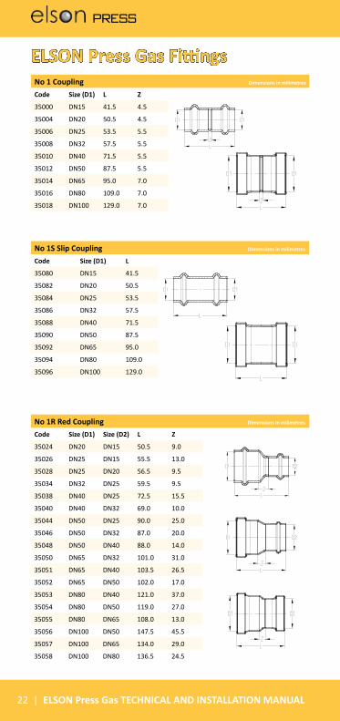
No 1 Coupling Dimensions in milimetres
Code Size (D1) L Z
35000 DN15 41.5 4.5
35004 DN20 50.5 4.5
35006 DN25 53.5 5.5
35008 DN32 57.5 5.5
35010 DN40 71.5 5.5
35012 DN50 87.5 5.5
35014 DN65 95.0 7.0
35016 DN80 109.0 7.0
35018 DN100 129.0 7.0
No 1R Red Coupling Dimensions in milimetres
Code Size (D1) Size (D2) L Z
35024 DN20 DN15 50.5 9.0
35026 DN25 DN15 55.5 13.0
35028 DN25 DN20 56.5 9.5
35034 DN32 DN25 59.5 9.5
35038 DN40 DN25 72.5 15.5
35040 DN40 DN32 69.0 10.0
35044 DN50 DN25 90.0 25.0
35046 DN50 DN32 87.0 20.0
35048 DN50 DN40 88.0 14.0
35050 DN65 DN32 101.0 31.0
35051 DN65 DN40 103.5 26.5
35052 DN65 DN50 102.0 17.0
35053 DN80 DN40 121.0 37.0
35054 DN80 DN50 119.0 27.0
35055 DN80 DN65 108.0 13.0
35056 DN100 DN50 147.5 45.5
35057 DN100 DN65 134.0 29.0
35058 DN100 DN80 136.5 24.5
No 1S Slip Coupling Dimensions in milimetres
Code Size (D1) L
35080 DN15 41.5
35082 DN20 50.5
35084 DN25 53.5
35086 DN32 57.5
35088 DN40 71.5
35090 DN50 87.5
35092 DN65 95.0
35094 DN80 109.0
35096 DN100 129.0
ELSON Press Gas Fittings
PRESS
ELSON Press Gas TECHNICAL AND INSTALLATION MANUAL | 23
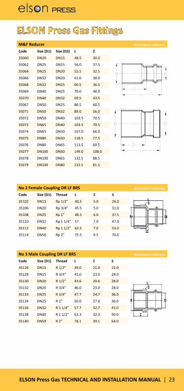
M&F Reducer Dimensions in milimetres
Code Size (D1) Size (D2) L Z
35060 DN20 DN15 48.5 30.0
35062 DN25 DN15 56.0 37.5
35064 DN25 DN20 55.5 32.5
35066 DN32 DN20 61.0 38.0
35068 DN32 DN25 60.5 36.5
35069 DN40 DN25 70.0 46.0
35070 DN40 DN32 69.5 43.5
35067 DN50 DN25 86.5 60.5
35071 DN50 DN32 89.0 56.0
35072 DN50 DN40 103.5 70.5
35073 DN65 DN40 103.5 70.5
35074 DN65 DN50 107.0 66.0
35075 DN80 DN50 118.5 77.5
35076 DN80 DN65 113.5 69.5
35077 DN100 DN50 149.0 108.0
35078 DN100 DN65 132.5 88.5
35079 DN100 DN80 132.5 81.5
No 3 Male Coupling DR LF BRS Dimensions in milimetres
Code Size (D1) Thread L Z S
35126 DN15 R 1/2” 39.0 21.0 22.0
35128 DN15 R 3/4” 41.0 23.0 28.0
35130 DN20 R 1/2” 43.6 20.6 28.0
35132 DN20 R 3/4” 46.0 23.0 28.0
35133 DN25 R 3/4” 47.7 24.7 36.0
35134 DN25 R 1” 50.0 27.0 36.0
35136 DN32 R 1 1/4” 57.7 32.7 43.0
35138 DN40 R 1 1/2” 63.3 32.3 50.0
35140 DN50 R 2” 78.1 39.1 64.0
No 2 Female Coupling DR LF BRS Dimensions in milimetres
Code Size (D1) Thread L Z S
35102 DN15 Rp 1/2” 40.5 5.0 26.0
35106 DN20 Rp 3/4” 45.5 5.0 31.0
35108 DN25 Rp 1” 48.5 6.0 37.5
35110 DN32 Rp 1 1/4” 57 7.0 47.0
35112 DN40 Rp 1 1/2” 62.5 7.0 53.0
35114 DN50 Rp 2” 75.5 9.5 70.0
ELSON Press Gas Fittings
PRESS
24 | ELSON Press Gas TECHNICAL AND INSTALLATION MANUAL
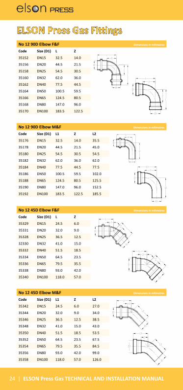
No 12 90D Elbow F&F Dimensions in milimetres
Code Size (D1) L Z
35152 DN15 32.5 14.0
35156 DN20 44.5 21.5
35158 DN25 54.5 30.5
35160 DN32 62.0 36.0
35162 DN40 77.5 44.5
35164 DN50 100.5 59.5
35166 DN65 124.5 80.5
35168 DN80 147.0 96.0
35170 DN100 183.5 122.5
No 12 45D Elbow F&F Dimensions in milimetres
Code Size (D1) L Z
35329 DN15 24.5 6.0
35331 DN20 32.0 9.0
35328 DN25 36.5 12.5
32330 DN32 41.0 15.0
35332 DN40 51.5 18.5
35334 DN50 64.5 23.5
35336 DN65 79.5 35.5
35338 DN80 93.0 42.0
35340 DN100 118.0 57.0
No 12 90D Elbow M&F Dimensions in milimetres
Code Size (D1) L1 Z L2
35176 DN15 32.5 14.0 35.5
35178 DN20 44.5 21.5 45.0
35180 DN25 54.5 30.5 54.5
35182 DN32 62.0 36.0 62.0
35184 DN40 77.5 44.5 77.5
35186 DN50 100.5 59.5 102.0
35188 DN65 124.5 80.5 125.5
35190 DN80 147.0 96.0 152.5
35192 DN100 183.5 122.5 185.5
No 12 45D Elbow M&F Dimensions in milimetres
Code Size (D1) L1 Z L2
35342 DN15 24.5 6.0 27.0
35344 DN20 32.0 9.0 34.0
35346 DN25 36.5 12.5 38.5
35348 DN32 41.0 15.0 43.0
35350 DN40 51.5 18.5 53.5
35352 DN50 64.5 23.5 67.5
35354 DN65 79.5 35.5 84.5
35356 DN80 93.0 42.0 99.0
35358 DN100 118.0 57.0 126.0
ELSON Press Gas Fittings

PRESS
ELSON Press Gas TECHNICAL AND INSTALLATION MANUAL | 25
No 13 Male Elbow DR LF BRS Dimensions in milimetres
Code Size (D1) Thread L1 L2 Z S
35430 DN15 R 1/2” 40.0 31.0 21.0 22.0
35432 DN20 R 3/4” 44.0 32.5 21.0 29.0
No 14 Female Elbow DR LF BRS Dimensions in milimetres
Code Size (D1) Thread L1 L2 Z S
35444 DN20 Rp 3/4” 44.0 29.8 21.0 31.0
No 15 Female Back Plate Elbow DR LF BRS Dimensions in milimetres
Code Size (D1)
Thread L1 L2 L3 L4 Z S
35364 DN15 Rp 1/2” 37.5 27.5 15.0 17.0 19.5 26.0
35366 DN20 Rp 3/4” 41.0 27.5 16.3 24.1 24.0 32.0
No 19 Male Back Plate Elbow DR LF BRS Dimensions in milimetres
Code Size (D1) Thread L1 L2 L3 L4 Z
35378 DN15 G 1/2” 16.0 30.0 45.0 38.0 20.0
35380 DN15 G 1/2” 16.0 30.0 65.0 38.0 20.0
ELSON Press Gas Fittings

PRESS
26 | ELSON Press Gas TECHNICAL AND INSTALLATION MANUAL
No 24 Tee Equal Dimensions in milimetres
Code Size (D1) L1 Z1 L2 Z2
35246 DN15 34.0 15.5 29.0 10.5
35250 DN20 44.0 21.0 37.5 14.5
35252 DN25 49.0 25.0 41.5 17.5
35254 DN32 51.0 25.0 48.0 22.0
35256 DN40 60.0 27.0 60.0 27.0
35258 DN50 74.5 33.5 74.5 33.5
35260 DN65 88.0 44.0 88.0 44.0
35262 DN80 100.0 49.0 100.0 49.0
35264 DN100 126.0 65.0 119.5 58.5
No 25 Tee Red Dimensions in milimetres
Code Size (D1)
Size (D2)
Size (D3)
L1 Z1 L2 Z2 L3 Z3
35272 DN20 DN20 DN15 44.0 21.0 40.5 22.0 37.5 14.535276 DN25 DN25 DN15 41.0 17.0 41.0 17.0 36.0 17.535278 DN25 DN25 DN20 44.0 20.0 44.0 20.0 41.0 18.035280 DN32 DN32 DN15 40.5 14.5 40.5 14.5 40.0 21.535281 DN32 DN32 DN20 45.0 19.0 45.0 19.0 46.0 23.035282 DN32 DN32 DN25 48.0 22.0 48.0 22.0 46.0 22.035283 DN40 DN40 DN20 51.0 18.0 51.0 18.0 49.5 26.535284 DN40 DN40 DN25 52.0 19.0 52.0 19.0 50.5 26.535286 DN40 DN40 DN32 54.5 21.5 54.5 21.5 54.5 28.535290 DN50 DN50 DN25 60.0 19.0 60.0 19.0 58.5 34.535294 DN50 DN50 DN40 67.0 26.0 67.0 26.0 66.5 33.535296 DN65 DN65 DN50 83.5 39.5 83.5 39.5 84.5 43.535298 DN80 DN80 DN50 89.5 38.5 89.5 38.5 90.0 49.035300 DN80 DN80 DN65 92.5 41.5 92.5 41.5 96.0 52.035302 DN100 DN100 DN50 103.0 42.0 103.0 42.0 103.5 62.535304 DN100 DN100 DN65 103.5 42.5 103.5 42.5 107.5 63.535305 DN100 DN100 DN80 112.0 51.0 112.0 51.0 114.0 63.0
ELSON Press Gas Fittings

PRESS
ELSON Press Gas TECHNICAL AND INSTALLATION MANUAL | 27
No 61 End Cap Dimensions in milimetres
Code Size (D1) L Z
35390 DN15 22.0 3.5
35392 DN20 27.5 4.5
35394 DN25 28.0 4.0
35396 DN32 30.0 4.0
35398 DN40 37.5 4.5
35400 DN50 48.0 7.0
No 61 End Cap W/port Dimensions in milimetres
Code Size (D1) L Z Rp
35402 DN65 79.5 19.5 Rp 3/4”
35404 DN80 94.5 27.5 Rp 3/4”
35406 DN100 113.5 36.0 Rp 3/4”
No 27 Tee Red Dimensions in milimetres
Code Size (D1)
Size (D2)
Size (D3)
L1 Z1 L2 Z2 L3 Z3
35270 DN20 DN15 DN15 40.5 17.5 40.5 22.0 32.5 14.0
No 26 Tee Red Dimensions in milimetres
Code Size (D1)
Size (D2)
Size (D3)
L1 Z1 L2 Z2 L3 Z3
35274 DN20 DN15 DN20 40.5 17.5 40.5 17.5 32.5 14.0
ELSON Press Gas Fittings
No 62 Female Connector Tapered DR LF BRS Dimensions in milimetres
Code Size (D1) Thread L Z S
35212 DN20 G 1/2” 40.0 22.0 26.0
35216 DN20 G 3/4” 45.0 22.0 31.0
PRESS
28 | ELSON Press Gas TECHNICAL AND INSTALLATION MANUAL
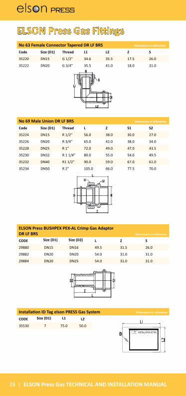
ELSON Press BUSHPEX PEX-AL Crimp Gas Adaptor DR LF BRS Dimensions in milimetres
CODE Size (D1) Size (D2) L Z S
29880 DN15 DN16 49.5 31.5 26.0
29882 DN20 DN20 54.0 31.0 31.0
29884 DN20 DN25 54.0 31.0 31.0
Installation ID Tag elson PRESS Gas System Dimensions in milimetres
CODE Size (D1) L1 L2
35530 7 75.0 50.0
No 63 Female Connector Tapered DR LF BRS Dimensions in milimetres
Code Size (D1) Thread L1 L2 Z S
35220 DN15 G 1/2” 34.6 35.5 17.5 26.0
35222 DN20 G 3/4” 35.5 41.0 18.0 31.0
No 69 Male Union DR LF BRS Dimensions in milimetres
Code Size (D1) Thread L Z S1 S2
35224 DN15 R 1/2” 56.0 38.0 30.0 27.0
35226 DN20 R 3/4” 65.0 42.0 38.0 34.0
35228 DN25 R 1” 72.0 49.0 47.0 43.5
35230 DN32 R 1 1/4” 80.0 55.0 54.0 49.5
35232 DN40 R1 1/2” 90.0 59.0 67.0 61.0
35234 DN50 R 2” 105.0 66.0 77.5 70.0
ELSON Press Gas Fittings
INSTALLATION ID TAG

PRESS
ELSON Press Gas TECHNICAL AND INSTALLATION MANUAL | 29
elson PRESS Gas Ball Valve DR LF BRS L/H Dimensions in milimetres
Code Size (D1) Thread L1 L2 H1 H2
73560 DN15 Rp 1/2” 65.4 90 46.4 62.2
73562 DN20 Rp 3/4” 82.2 103.5 53.3 72.8
elson PRESS Gas Ball Valve DR LF BRS L/H Dimensions in milimetres
Code Size (D1) L1 L2 H1 H2
73580 DN15 90 46.4 62.2 27.0
73582 DN20 103.5 53.3 72.8 34.0
73584 DN25 103.5 57.3 80.9 43.5
73586 DN32 135 65.6 94.7 49.5
73588 DN40 135 71.7 107.3 61.0
73590 DN50 165 89.6 132.9 70.0
ELSON Press Gas Ball Valves

PRESS
30 | ELSON Press Gas TECHNICAL AND INSTALLATION MANUAL