THE BMW M5 SEDAN. - Dealer eProcesscdn.dealereprocess.com/cdn/servicemanuals/bmw/2016-m5.pdfM5...
239
BMW M The Ultimate Driving Machine® THE BMW M5 SEDAN. OWNER'S MANUAL. Contents A-Z Online Edition for Part no. 01 40 2 954 339 - II/15
Transcript of THE BMW M5 SEDAN. - Dealer eProcesscdn.dealereprocess.com/cdn/servicemanuals/bmw/2016-m5.pdfM5...
BMW M
The UltimateDriving Machine®
THE BMW M5 SEDAN.OWNER'S MANUAL.
ContentsA-Z
Online Edition for Part no. 01 40 2 954 339 - II/15
Information Provided by:

Information Provided by:
M5 Owner's Manual for VehicleThank you for choosing a BMW M5.The more familiar you are with your vehicle, the better controlyou will have on the road. We therefore strongly suggest:Read this Owner's Manual before starting off in your newBMW M5. Also use the Integrated Owner's Manual in your vehi‐cle. It contains important information on vehicle operation thatwill help you make full use of the technical features available inyour BMW M5. The manual also contains information designedto enhance operating reliability and road safety, and to contrib‐ute to maintaining the value of your BMW M5.Any updates made after the editorial deadline for the printed orIntegrated Owner's Manual are found in the appendix of theprinted Quick Reference for the vehicle.Supplementary information can be found in the additional bro‐chures in the onboard literature.We wish you a safe and enjoyable ride.BMW AG
The Owner's Manual is available in many countries as an app.Additional information on the Internet:www.bmw.com/bmw_drivers_guide
Online Edition for Part no. 01 40 2 954 339 - II/15
Information Provided by:

© 2015 Bayerische Motoren WerkeAktiengesellschaftMunich, GermanyReprinting, including excerpts, only with the writtenconsent of BMW AG, Munich.US English II/15, 03 15 490Printed on environmentally friendly paper, bleachedwithout chlorine, suitable for recycling.
Online Edition for Part no. 01 40 2 954 339 - II/15
Information Provided by:
Addendum
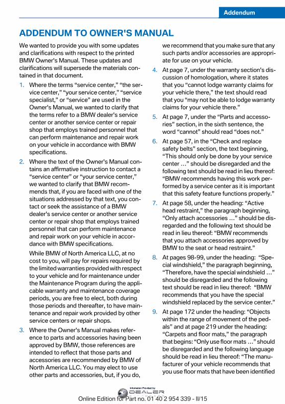
ADDENDUM TO OWNER'S MANUALWe wanted to provide you with some updates and clarifications with respect to the printed BMW Owner's Manual. These updates and clarifications will supersede the materials con-tained in that document. 1. Where the terms “service center,” “the ser-
vice center,” “your service center,” “service specialist,” or “service” are used in the Owner's Manual, we wanted to clarify that the terms refer to a BMW dealer's service center or another service center or repair shop that employs trained personnel that can perform maintenance and repair work on your vehicle in accordance with BMW specifications.
2. Where the text of the Owner's Manual con-tains an affirmative instruction to contact a “service center” or “your service center,” we wanted to clarify that BMW recom-mends that, if you are faced with one of the situations addressed by that text, you con-tact or seek the assistance of a BMW dealer's service center or another service center or repair shop that employs trained personnel that can perform maintenance and repair work on your vehicle in accor-dance with BMW specifications. While BMW of North America LLC, at no cost to you, will pay for repairs required by the limited warranties provided with respect to your vehicle and for maintenance under the Maintenance Program during the appli-cable warranty and maintenance coverage periods, you are free to elect, both during those periods and thereafter, to have main-tenance and repair work provided by other service centers or repair shops.
3. Where the Owner's Manual makes refer-ence to parts and accessories having been approved by BMW, those references are intended to reflect that those parts and accessories are recommended by BMW of North America LLC. You may elect to use other parts and accessories, but, if you do,
we recommend that you make sure that any such parts and/or accessories are appropri-ate for use on your vehicle.
4. At page 7, under the warranty section's dis-cussion of homologation, where it states that you “cannot lodge warranty claims for your vehicle there,” the text should read that you “may not be able to lodge warranty claims for your vehicle there.”
5. At page 7, under the “Parts and accesso-ries” section, in the sixth sentence, the word “cannot” should read “does not.”
6. At page 57, in the “Check and replace safety belts” section, the text beginning, “This should only be done by your service center …” should be disregarded and the following text should be read in lieu thereof: “BMW recommends having this work per-formed by a service center as it is important that this safety feature functions properly.”
7. At page 58, under the heading: “Active head restraint,” the paragraph beginning, “Only attach accessories …” should be dis-regarded and the following text should be read in lieu thereof: “BMW recommends that you attach accessories approved by BMW to the seat or head restraint.”
8. At pages 98-99, under the heading: “Spe-cial windshield,” the paragraph beginning, “Therefore, have the special windshield …” should be disregarded and the following text should be read in lieu thereof: “BMW recommends that you have the special windshield replaced by the service center.”
9. At page 172 under the heading: “Objects within the range of movement of the ped-als” and at page 219 under the heading: “Carpets and floor mats,” the paragraph that begins: “Only use floor mats …” should be disregarded and the following language should be read in lieu thereof: “The manu-facturer of your vehicle recommends that you use floor mats that have been identified
Online Edition for Part no. 01 40 2 954 339 - II/15
Information Provided by:
Addendum
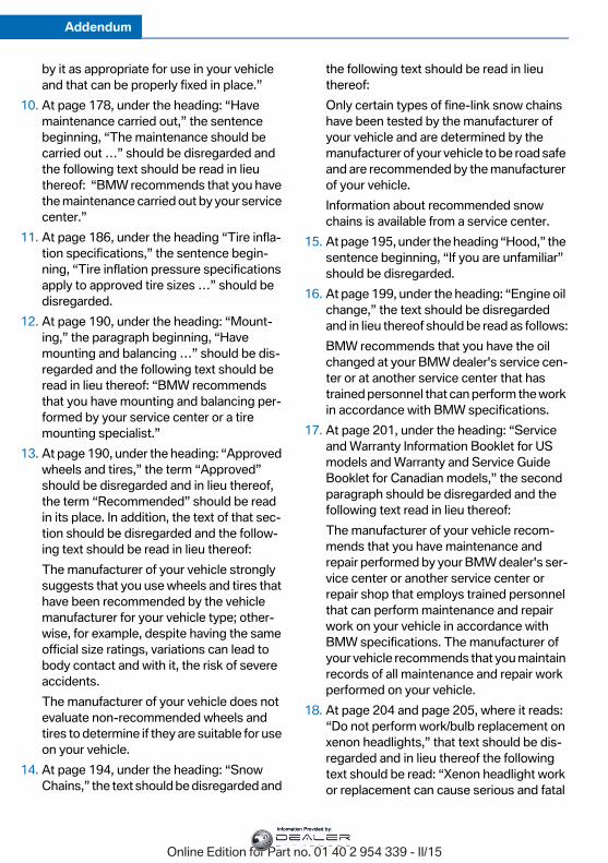
by it as appropriate for use in your vehicle and that can be properly fixed in place.”
10. At page 178, under the heading: “Have maintenance carried out,” the sentence beginning, “The maintenance should be carried out …” should be disregarded and the following text should be read in lieu thereof: “BMW recommends that you have the maintenance carried out by your service center.”
11. At page 186, under the heading “Tire infla-tion specifications,” the sentence begin-ning, “Tire inflation pressure specifications apply to approved tire sizes …” should be disregarded.
12. At page 190, under the heading: “Mount-ing,” the paragraph beginning, “Have mounting and balancing …” should be dis-regarded and the following text should be read in lieu thereof: “BMW recommends that you have mounting and balancing per-formed by your service center or a tire mounting specialist.”
13. At page 190, under the heading: “Approved wheels and tires,” the term “Approved” should be disregarded and in lieu thereof, the term “Recommended” should be read in its place. In addition, the text of that sec-tion should be disregarded and the follow-ing text should be read in lieu thereof: The manufacturer of your vehicle strongly suggests that you use wheels and tires that have been recommended by the vehicle manufacturer for your vehicle type; other-wise, for example, despite having the same official size ratings, variations can lead to body contact and with it, the risk of severe accidents. The manufacturer of your vehicle does not evaluate non-recommended wheels and tires to determine if they are suitable for use on your vehicle.
14. At page 194, under the heading: “Snow Chains,” the text should be disregarded and
the following text should be read in lieu thereof: Only certain types of fine-link snow chains have been tested by the manufacturer of your vehicle and are determined by the manufacturer of your vehicle to be road safe and are recommended by the manufacturer of your vehicle. Information about recommended snow chains is available from a service center.
15. At page 195, under the heading “Hood,” the sentence beginning, “If you are unfamiliar” should be disregarded.
16. At page 199, under the heading: “Engine oil change,” the text should be disregarded and in lieu thereof should be read as follows:BMW recommends that you have the oil changed at your BMW dealer's service cen-ter or at another service center that has trained personnel that can perform the work in accordance with BMW specifications.
17. At page 201, under the heading: “Service and Warranty Information Booklet for US models and Warranty and Service Guide Booklet for Canadian models,” the second paragraph should be disregarded and the following text read in lieu thereof: The manufacturer of your vehicle recom-mends that you have maintenance and repair performed by your BMW dealer's ser-vice center or another service center or repair shop that employs trained personnel that can perform maintenance and repair work on your vehicle in accordance with BMW specifications. The manufacturer of your vehicle recommends that you maintain records of all maintenance and repair work performed on your vehicle.
18. At page 204 and page 205, where it reads: “Do not perform work/bulb replacement on xenon headlights,” that text should be dis-regarded and in lieu thereof the following text should be read: “Xenon headlight work or replacement can cause serious and fatal
Online Edition for Part no. 01 40 2 954 339 - II/15
Information Provided by:
Addendum
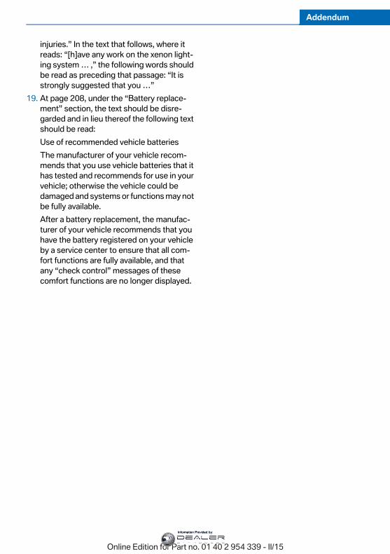
injuries.” In the text that follows, where it reads: “[h]ave any work on the xenon light-ing system … ,” the following words should be read as preceding that passage: “It is strongly suggested that you …”
19. At page 208, under the “Battery replace-ment” section, the text should be disre-garded and in lieu thereof the following text should be read: Use of recommended vehicle batteriesThe manufacturer of your vehicle recom-mends that you use vehicle batteries that it has tested and recommends for use in your vehicle; otherwise the vehicle could be damaged and systems or functions may not be fully available.After a battery replacement, the manufac-turer of your vehicle recommends that you have the battery registered on your vehicle by a service center to ensure that all com-fort functions are fully available, and that any “check control” messages of these comfort functions are no longer displayed.
Online Edition for Part no. 01 40 2 954 339 - II/15
Information Provided by:

Information Provided by:
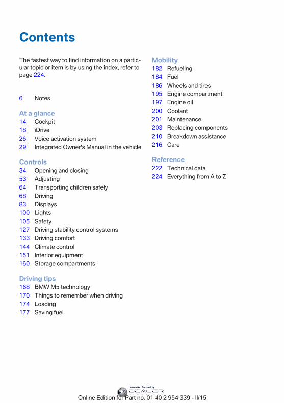
ContentsThe fastest way to find information on a partic‐ular topic or item is by using the index, refer topage 224.
6 Notes
At a glance14 Cockpit18 iDrive26 Voice activation system29 Integrated Owner's Manual in the vehicle
Controls34 Opening and closing53 Adjusting64 Transporting children safely68 Driving83 Displays100 Lights105 Safety127 Driving stability control systems133 Driving comfort144 Climate control151 Interior equipment160 Storage compartments
Driving tips168 BMW M5 technology170 Things to remember when driving174 Loading177 Saving fuel
Mobility182 Refueling184 Fuel186 Wheels and tires195 Engine compartment197 Engine oil200 Coolant201 Maintenance203 Replacing components210 Breakdown assistance216 Care
Reference222 Technical data224 Everything from A to Z
Online Edition for Part no. 01 40 2 954 339 - II/15
Information Provided by:
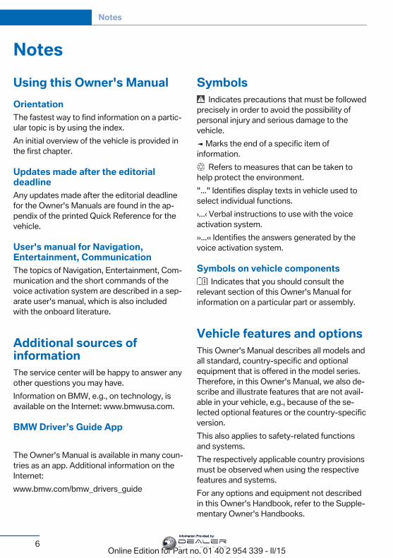
NotesUsing this Owner's ManualOrientationThe fastest way to find information on a partic‐ular topic is by using the index.An initial overview of the vehicle is provided inthe first chapter.
Updates made after the editorialdeadlineAny updates made after the editorial deadlinefor the Owner's Manuals are found in the ap‐pendix of the printed Quick Reference for thevehicle.
User's manual for Navigation,Entertainment, CommunicationThe topics of Navigation, Entertainment, Com‐munication and the short commands of thevoice activation system are described in a sep‐arate user's manual, which is also includedwith the onboard literature.
Additional sources ofinformationThe service center will be happy to answer anyother questions you may have.Information on BMW, e.g., on technology, isavailable on the Internet: www.bmwusa.com.
BMW Driver’s Guide App
The Owner's Manual is available in many coun‐tries as an app. Additional information on theInternet:www.bmw.com/bmw_drivers_guide
Symbols Indicates precautions that must be followed
precisely in order to avoid the possibility ofpersonal injury and serious damage to thevehicle.◄ Marks the end of a specific item ofinformation.
Refers to measures that can be taken tohelp protect the environment."..." Identifies display texts in vehicle used toselect individual functions.›...‹ Verbal instructions to use with the voiceactivation system.››...‹‹ Identifies the answers generated by thevoice activation system.
Symbols on vehicle components Indicates that you should consult the
relevant section of this Owner's Manual forinformation on a particular part or assembly.
Vehicle features and optionsThis Owner's Manual describes all models andall standard, country-specific and optionalequipment that is offered in the model series.Therefore, in this Owner's Manual, we also de‐scribe and illustrate features that are not avail‐able in your vehicle, e.g., because of the se‐lected optional features or the country-specificversion.This also applies to safety-related functionsand systems.The respectively applicable country provisionsmust be observed when using the respectivefeatures and systems.For any options and equipment not describedin this Owner's Handbook, refer to the Supple‐mentary Owner's Handbooks.
Seite 6
Notes
6Online Edition for Part no. 01 40 2 954 339 - II/15
Information Provided by:
On right-hand drive vehicles, some controlsare arranged differently from what is shown inthe illustrations.
Status of the Owner'sManualBasic informationThe manufacturer of your vehicle pursues apolicy of constant development that is con‐ceived to ensure that our vehicles continue toembody the highest quality and safety stan‐dards. In rare cases, therefore, the features de‐scribed in this Owner's Manual may differ fromthose in your vehicle.
Updates made after the editorialdeadlineAny updates made after the editorial deadlinefor the Owner's Manuals are found in the ap‐pendix of the printed Quick Reference for thevehicle.
For your own safetyWarrantyYour vehicle is technically configured for theoperating conditions and registration require‐ments applying in the country of first delivery -homologation. If your vehicle is to be operatedin a different country it might be necessary toadapt your vehicle to potentially differing oper‐ating conditions and permit requirements. Ifyour vehicle does not comply with the homolo‐gation requirements in a certain country youcannot lodge warranty claims for your vehiclethere. Further information can be obtainedfrom your Service Centre.
Maintenance and repairsAdvanced technology, e.g., the use of modernmaterials and high-performance electronics,requires suitable maintenance and repair work.
Therefore, have this work performed only by aBMW center or a workshop that works accord‐ing to BMW repair procedures with appropri‐ately trained personnel.If work is not carried out properly, there is adanger of subsequent damage and relatedsafety hazards.
Parts and accessoriesBMW recommends using parts and accesso‐ries approved by BMW for this purpose.Your BMW center is the right contact for genu‐ine BMW parts and accessories, other prod‐ucts approved by BMW and related qualifiedadvice.BMW has tested these products for safety andsuitability in relation to BMW vehicles.BMW can assume responsibility for them.However, we cannot assume any responsibilitywhatsoever for parts and accessories that havenot been specifically approved by BMW.BMW cannot evaluate whether each individualproduct from another manufacturer can beused with BMW vehicles without presenting asafety hazard. This guarantee does not applywhen country-specific government approvalhas been granted. Testing of this kind may failto embrace the entire range of potential oper‐ating conditions to which components mightbe exposed on BMW vehicles. Such productscould conceivably fail to comply with BMW'sown stringent quality standards.
California Proposition 65 WarningCalifornia laws require us to state the followingwarning:Engine exhaust and a wide variety of automo‐bile components and parts, including compo‐nents found in the interior furnishings in a vehi‐cle, contain or emit chemicals known to theState of California to cause cancer and birthdefects and reproductive harm. In addition,certain fluids contained in vehicles and certainproducts of component wear contain or emit
Seite 7
Notes
7Online Edition for Part no. 01 40 2 954 339 - II/15
Information Provided by:
chemicals known to the State of California tocause cancer and birth defects or other repro‐ductive harm. Battery posts, terminals and re‐lated accessories contain lead and lead com‐pounds. Wash your hands after handling. Usedengine oil contains chemicals that have causedcancer in laboratory animals. Always protectyour skin by washing thoroughly with soap andwater.
Service and warrantyWe recommend that you read this publicationthoroughly. Your vehicle is covered by the fol‐lowing warranties:▷ New Vehicle Limited Warranty.▷ Rust Perforation Limited Warranty.▷ Federal Emissions System Defect War‐
ranty.▷ Federal Emissions Performance Warranty.▷ California Emission Control System Lim‐
ited Warranty.Detailed information about these warranties islisted in the Service and Warranty InformationBooklet for US models or in the Warranty andService Guide Booklet for Canadian models.Your vehicle has been specifically adapted anddesigned to meet the particular operating con‐ditions and homologation requirements in yourcountry and continental region in order to de‐liver the full driving pleasure while the vehicleis operated under those conditions. If you wishto operate your vehicle in another country orregion, you may be required to adapt your ve‐hicle to meet different prevailing operatingconditions and homologation requirements.You should also be aware of any applicablewarranty limitations or exclusions for suchcountry or region. In such case, please contactCustomer Relations for further information.
MaintenanceMaintain the vehicle regularly to sustain theroad safety, operational reliability and the NewVehicle Limited Warranty.
Specifications for required maintenance meas‐ures:▷ BMW Maintenance system▷ Service and Warranty Information Booklet
for US models▷ Warranty and Service Guide Booklet for
Canadian modelsIf the vehicle is not maintained according tothese specifications, this could result in seri‐ous damage to the vehicle. Such damage isnot covered by the BMW New Vehicle LimitedWarranty.
Data memoryMany electronic components on your vehicleare equipped with data memories that tempo‐rarily or permanently store technical informa‐tion about the condition of the vehicle, eventsand faults. This technical information generallyrecords the state of a component, a module, asystem or the environment:▷ Operating mode of system components, fill
levels for instance.▷ Status messages for the vehicle and from
its individual components, e.g., wheel rota‐tion speed/vehicle speed, deceleration,transverse acceleration.
▷ Malfunctions and faults in important sys‐tem components, e.g., lights and brakes.
▷ Responses by the vehicle to special situa‐tions such as airbag deployment or engag‐ing the stability control system.
▷ Ambient conditions, such as temperature.This data is purely technical in nature and isused to detect and correct faults and to opti‐mize vehicle functions. Motion profiles overroutes traveled cannot be created from thisdata. When service offerings are used, e.g., re‐pair services, service processes, warrantyclaims, quality assurance, this technical infor‐mation can be read out from the event andfault memories by the service personnel, in‐
Seite 8
Notes
8Online Edition for Part no. 01 40 2 954 339 - II/15
Information Provided by:
cluding the manufacturer, using special diag‐nostic tools. You can obtain further informationthere if you need it. After an error is corrected,the information in the fault memory is deletedor overwritten on a continuous basis.With the vehicle in use there are situationswhere you can associate these technical datawith individuals if combined with other infor‐mation, e.g., an accident report, damage to thevehicle, eye witness accounts — possibly withthe assistance of an expert.Additional functions that are contractuallyagreed with the customer - such as vehicleemergency locating - you can transmit certainvehicle data from the vehicle.
Event Data Recorder EDRThis vehicle is equipped with an event data re‐corder EDR. The main purpose of an EDR is torecord, in certain crash or near crash-like situa‐tions, such as an air bag deployment or hittinga road obstacle, data that will assist in under‐standing how a vehicle’s systems performed.The EDR is designed to record data related tovehicle dynamics and safety systems for ashort period of time, typically 30 seconds orless.The EDR in this vehicle is designed to recordsuch data as:▷ How various systems in your vehicle were
operating.▷ Whether or not the driver and passenger
safety belts were fastened.▷ How far, if at all, the driver was depressing
the accelerator and/or brake pedal.▷ How fast the vehicle was traveling.These data can help provide a better under‐standing of the circumstances in whichcrashes and injuries occur.EDR data are recorded by your vehicle only if anontrivial crash situation occurs; no data arerecorded by the EDR under normal driving
conditions and no personal data, e.g., name,gender, age, and crash location, are recorded.However, other parties, such as law enforce‐ment, could combine the EDR data with thetype of personally identifying data routinely ac‐quired during a crash investigation.To read data recorded by an EDR, specialequipment is required, and access to the vehi‐cle or the EDR is needed. In addition to the ve‐hicle manufacturer, other parties, such as lawenforcement, that have the special equipment,can read the information if they have access tothe vehicle or the EDR.
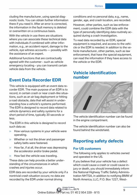
Vehicle identificationnumber
The vehicle identification number can be foundin the engine compartment.
The vehicle identification number can also befound behind the windshield.
Reporting safety defectsFor US customersThe following only applies to vehicles ownedand operated in the US.If you believe that your vehicle has a defectwhich could cause a crash or could cause in‐jury or death, you should immediately informthe National Highway Traffic Safety Adminis‐tration NHTSA, in addition to notifying BMW ofNorth America, LLC, P.O. Box 1227, West‐
Seite 9
Notes
9Online Edition for Part no. 01 40 2 954 339 - II/15
Information Provided by:
wood, New Jersey 07675-1227, Telephone1-800-831-1117.If NHTSA receives similar complaints, it mayopen an investigation, and if it finds that asafety defect exists in a group of vehicles, itmay order a recall and remedy campaign.However, NHTSA cannot become involved inindividual problems between you, your dealer,or BMW of North America, LLC.To contact NHTSA, you may call the VehicleSafety Hotline toll-free at 1-888-327-4236(TTY: 1-800-424-9153); go to http://www.safercar.gov; or write to: Administrator,NHTSA, 400 Seventh Street, SW., Washing‐ton, DC 20590. You can also obtain other in‐formation about motor vehicle safety fromhttp://www.safercar.gov.
For Canadian customersCanadian customers who wish to report asafety-related defect to Transport Canada, De‐fect Investigations and Recalls, may call thetoll-free hotline 1-800-333-0510. You can alsoobtain other information about motor vehiclesafety from http://www.tc.gc.ca/roadsafety.
Seite 10
Notes
10Online Edition for Part no. 01 40 2 954 339 - II/15
Information Provided by:

Seite 11
Notes
11Online Edition for Part no. 01 40 2 954 339 - II/15
Information Provided by:
Online Edition for Part no. 01 40 2 954 339 - II/15
Information Provided by:
At a glanceThese overviews of buttons, switches and
displays are intended to familiarize you with yourvehicle. You will also become quickly acquaintedwith the available control concepts and options.
Online Edition for Part no. 01 40 2 954 339 - II/15
Information Provided by:
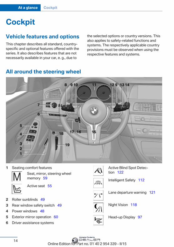
CockpitVehicle features and optionsThis chapter describes all standard, country-specific and optional features offered with theseries. It also describes features that are notnecessarily available in your car, e. g., due to
the selected options or country versions. Thisalso applies to safety-related functions andsystems. The respectively applicable countryprovisions must be observed when using therespective features and systems.
All around the steering wheel
1 Seating comfort featuresSeat, mirror, steering wheelmemory 59
Active seat 55
2 Roller sunblinds 493 Rear window safety switch 494 Power windows 485 Exterior mirror operation 606 Driver assistance systems
Active Blind Spot Detec‐tion 122
Intelligent Safety 112
Lane departure warning 121
Night Vision 118
Head-up Display 97
Seite 14
At a glance Cockpit
14Online Edition for Part no. 01 40 2 954 339 - II/15
Information Provided by:
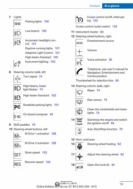
7 LightsParking lights 100
Low beams 100
Automatic headlight con‐trol 101Daytime running lights 101Adaptive Light Control 101High-beam Assistant 102Instrument lighting 103
8 Steering column stalk, leftTurn signal 74
High beams, head‐light flasher 74
High-beam Assistant 102
Roadside parking lights 101
On-board computer 93
9 Shift paddles 7910 Steering wheel buttons, left
M Drive 1 activation 128
M Drive 2 activation 128
Store speed 133
Resume speed 134
Cruise control on/off, interrupt‐ing 133
Cruise control rocker switch 134
11 Instrument cluster 8312 Steering wheel buttons, right
Entertainment source
Volume
Voice activation 26
Telephone, see user's manual forNavigation, Entertainment andCommunication
Thumbwheel for selection lists 93
13 Steering column stalk, rightWiper 74
Rain sensor 75
Clean the windshields and head‐lights 74
14 Start/stop the engine and switchthe ignition on/off 69
Auto Start/Stop function 70
15 Horn, total area16 Steering wheel heating 63
17 Adjust the steering wheel 62
18 Open the trunk lid 40
Seite 15
Cockpit At a glance
15Online Edition for Part no. 01 40 2 954 339 - II/15
Information Provided by:
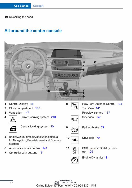
19 Unlocking the hood
All around the center console
1 Control Display 182 Glove compartment 1603 Ventilation 1474 Hazard warning system 210
Central locking system 40
5 Radio/CD/Multimedia, see user's manualfor Navigation, Entertainment and Commu‐nication
6 Automatic climate control 1447 Controller with buttons 18
8 PDC Park Distance Control 135Top View 141Rearview camera 137Side View 140
9 Parking brake 72
10 Drivelogic 79
11 DSC Dynamic Stability Con‐trol 129
Engine Dynamics 81
Seite 16
At a glance Cockpit
16Online Edition for Part no. 01 40 2 954 339 - II/15
Information Provided by:
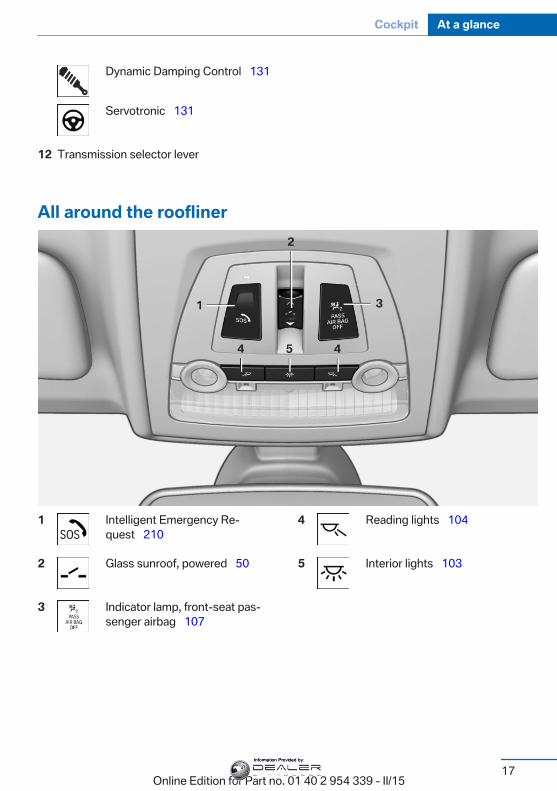
Dynamic Damping Control 131
Servotronic 131
12 Transmission selector lever
All around the roofliner
1 Intelligent Emergency Re‐quest 210
2 Glass sunroof, powered 50
3 Indicator lamp, front-seat pas‐senger airbag 107
4 Reading lights 104
5 Interior lights 103
Seite 17
Cockpit At a glance
17Online Edition for Part no. 01 40 2 954 339 - II/15
Information Provided by:

iDriveVehicle features and optionsThis chapter describes all standard, country-specific and optional features offered with theseries. It also describes features that are notnecessarily available in your car, e. g., due tothe selected options or country versions. Thisalso applies to safety-related functions andsystems. The respectively applicable countryprovisions must be observed when using therespective features and systems.
The conceptThe iDrive combines the functions of manyswitches. Thus, these functions can be oper‐ated from a central location.
Using the iDrive during a tripTo avoid becoming distracted and pos‐
ing an unnecessary hazard to your vehicle'soccupants and to other traffic, never attemptto use the controls or enter information unlesstraffic and road conditions allow it.◀
Control elements at a glanceControl elements
1 Control Display2 Controller with buttons and, depending on
the equipment version, with touchpad
Control Display
Hints▷ To clean the Control Display, follow the
care instructions.▷ Do not place objects close to the Control
Display; otherwise, the Control Display canbe damaged.
▷ In the case of very high temperatures onthe Control Display, e.g. due to intense so‐lar radiation, the brightness may be re‐duced down to complete deactivation.Once the temperature is reduced, e.g.through shadow or climate control system,the normal functions are re-established.
Switching on1. Switch on the ignition.2. Press the controller.
Switch off
1. Press button.2. "Turn off control display"
ControllerThe buttons can be used to open the menusdirectly. The controller can be used to selectmenu items and enter the settings.Some iDrive functions can be operated usingthe touchpad on the controller.
Seite 18
At a glance iDrive
18Online Edition for Part no. 01 40 2 954 339 - II/15
Information Provided by:
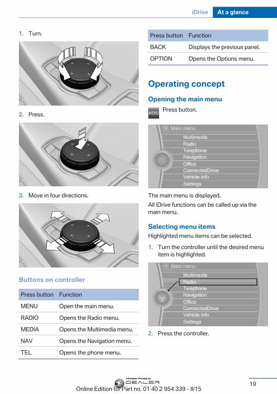
1. Turn.
2. Press.
3. Move in four directions.
Buttons on controller
Press button Function
MENU Open the main menu.
RADIO Opens the Radio menu.
MEDIA Opens the Multimedia menu.
NAV Opens the Navigation menu.
TEL Opens the phone menu.
Press button Function
BACK Displays the previous panel.
OPTION Opens the Options menu.
Operating conceptOpening the main menu
Press button.
The main menu is displayed.All iDrive functions can be called up via themain menu.
Selecting menu itemsHighlighted menu items can be selected.
1. Turn the controller until the desired menuitem is highlighted.
2. Press the controller.
Seite 19
iDrive At a glance
19Online Edition for Part no. 01 40 2 954 339 - II/15
Information Provided by:
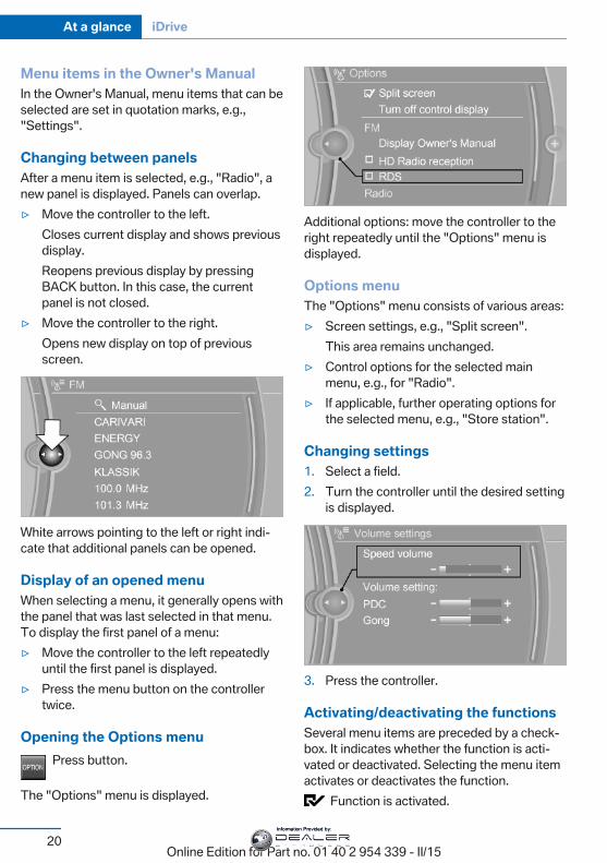
Menu items in the Owner's ManualIn the Owner's Manual, menu items that can beselected are set in quotation marks, e.g.,"Settings".
Changing between panelsAfter a menu item is selected, e.g., "Radio", anew panel is displayed. Panels can overlap.▷ Move the controller to the left.
Closes current display and shows previousdisplay.Reopens previous display by pressingBACK button. In this case, the currentpanel is not closed.
▷ Move the controller to the right.Opens new display on top of previousscreen.
White arrows pointing to the left or right indi‐cate that additional panels can be opened.
Display of an opened menuWhen selecting a menu, it generally opens withthe panel that was last selected in that menu.To display the first panel of a menu:▷ Move the controller to the left repeatedly
until the first panel is displayed.▷ Press the menu button on the controller
twice.
Opening the Options menuPress button.
The "Options" menu is displayed.
Additional options: move the controller to theright repeatedly until the "Options" menu isdisplayed.
Options menuThe "Options" menu consists of various areas:▷ Screen settings, e.g., "Split screen".
This area remains unchanged.▷ Control options for the selected main
menu, e.g., for "Radio".▷ If applicable, further operating options for
the selected menu, e.g., "Store station".
Changing settings1. Select a field.2. Turn the controller until the desired setting
is displayed.
3. Press the controller.
Activating/deactivating the functionsSeveral menu items are preceded by a check‐box. It indicates whether the function is acti‐vated or deactivated. Selecting the menu itemactivates or deactivates the function.
Function is activated.
Seite 20
At a glance iDrive
20Online Edition for Part no. 01 40 2 954 339 - II/15
Information Provided by:
Function is deactivated.
TouchpadSome iDrive functions can be operated usingthe touchpad on the controller:
Selecting functions1. "Settings"2. "Touchpad"3. Select the desired function.
▷ "Speller": enter letters and numbers.▷ "Interactive map": viewing the interac‐
tive map.▷ "Browser": enter Internet addresses.▷ "Audio feedback": pronounces entered
letters and numbers.
Entering letters and numbersEntering letters requires some practice at thebeginning. When entering, pay attention to thefollowing:▷ For the input of upper/lower case letters
and numbers, it may be necessary to reelvia the controller to the corresponding In‐put mode, refer to page 24, e.g. when thespelling of upper and lower case letters isidentical.
▷ Enter characters as they are displayed onthe Control Display.
▷ Always enter associated characters, suchas accents or periods so that the letter canbe clearly recognized. Possible input de‐pends on the set language. Where neces‐sary, enter special characters via the con‐troller.
▷ To delete a character, slide to the left onthe touchpad.
▷ To enter a blank space, slide to the right inthe center of the touchpad.
▷ To enter a hyphen, slide to the right in theupper area of the touchpad.
▷ To enter an underscore, swipe to the rightin the lower area of the touchpad.
Using interactive map and InternetVia touch-pad move the interactive map in thenavigation system and Internet sites.
Function Controls
Move interactive map orInternet sites.
Swipe into re‐spective direc‐tion.
Enlarge/shrink interactivemap or Internet sites.
Drag in or out onthe touchpad withfingers.
Display the menu or opena link in the Internet.
Tap once.
Changing settingsYou may change control display settings viatouchpad. Swipe left or right accordingly.
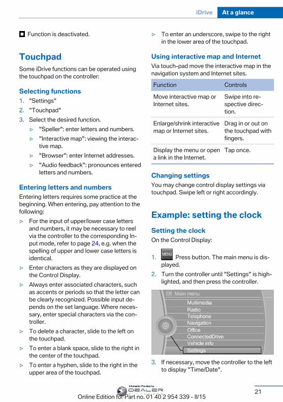
Example: setting the clockSetting the clockOn the Control Display:
1. Press button. The main menu is dis‐played.
2. Turn the controller until "Settings" is high‐lighted, and then press the controller.
3. If necessary, move the controller to the leftto display "Time/Date".
Seite 21
iDrive At a glance
21Online Edition for Part no. 01 40 2 954 339 - II/15
Information Provided by:
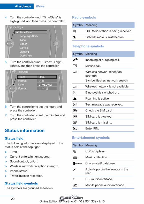
4. Turn the controller until "Time/Date" ishighlighted, and then press the controller.
5. Turn the controller until "Time:" is high‐lighted, and then press the controller.
6. Turn the controller to set the hours andpress the controller.
7. Turn the controller to set the minutes andpress the controller.
Status informationStatus fieldThe following information is displayed in thestatus field at the top right:▷ Time.▷ Current entertainment source.▷ Sound output, on/off.▷ Wireless network reception strength.▷ Phone status.▷ Traffic bulletin reception.
Status field symbolsThe symbols are grouped as follows.
Radio symbols
Symbol Meaning
HD Radio station is being received.
Satellite radio is switched on.
Telephone symbols
Symbol Meaning
Incoming or outgoing call.
Missed call.
Wireless network receptionstrength.Symbol flashes: network search.
Wireless network is not available.
Bluetooth is switched on.
Roaming is active.
Text message was received.
Check the SIM card.
SIM card is blocked.
SIM card is missing.
Enter PIN.
Entertainment symbols
Symbol Meaning
CD/DVD player.
Music collection.
Gracenote® database.
AUX-IN port in the front or in therear.
USB audio interface.
Mobile phone audio interface.
Seite 22
At a glance iDrive
22Online Edition for Part no. 01 40 2 954 339 - II/15
Information Provided by:
Additional symbols
Symbol Meaning
Spoken instructions are turned off.
Split screenGeneral informationAdditional information can be displayed on theright side of the split screen, e.g., informationfrom the on-board comupter.In the divided screen view, the so-called splitscreen, this information remains visible evenwhen you change to another menu.
Switching the split screen on and offOn the Control Display:
1. Press button.2. "Split screen"
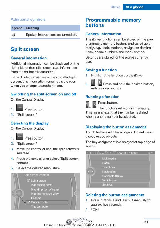
Selecting the displayOn the Control Display:
1. Press button.2. "Split screen"3. Move the controller until the split screen is
selected.4. Press the controller or select "Split screen
content".5. Select the desired menu item.
Programmable memorybuttonsGeneral informationThe iDrive functions can be stored on the pro‐grammable memory buttons and called up di‐rectly, e.g., radio stations, navigation destina‐tions, phone numbers and menu entries.Settings are stored for the profile currently inuse.
Saving a function1. Highlight the function via the iDrive.
2. Press and hold the desired button,until a signal sounds.
Running a functionPress button.The function will work immediately.
This means, e.g., that the number is dialedwhen a phone number is selected.
Displaying the button assignmentTouch buttons with bare fingers. Do not weargloves or use objects.The key assignment is displayed at top edge ofscreen.
Deleting the button assignments1. Press buttons 1 and 8 simultaneously for
approx. five seconds.2. "OK"
Seite 23
iDrive At a glance
23Online Edition for Part no. 01 40 2 954 339 - II/15
Information Provided by:
Deleting personal in thevehicleThe conceptDepending on the usage, the vehicle savespersonal data, such as stored radio stations.These personal data can be permanently de‐leted through iDrive.
General informationDepending on the equipment package, the fol‐lowing data can be deleted:▷ Personal Profile settings.▷ Stored radio stations.▷ Stored Favorites buttons.▷ Travel and computer information.▷ Music collection.▷ Navigation, e.g. stored destinations.▷ Phone book.▷ Online data, e.g. Favorites, cookies.▷ Voice notes.▷ Login accounts.▷ RemoteApp smartphone tethering.Altogether, the deletion of the data can take upto 30 minutes.
Functional requirementData can only be deleted while stationary.
Deleting dataHeed and follow the instructions on the Con‐trol Display.
1. Switch on the ignition.2. "Settings"3. Open "Options".4. "Delete personal data"5. "Continue"6. "OK"
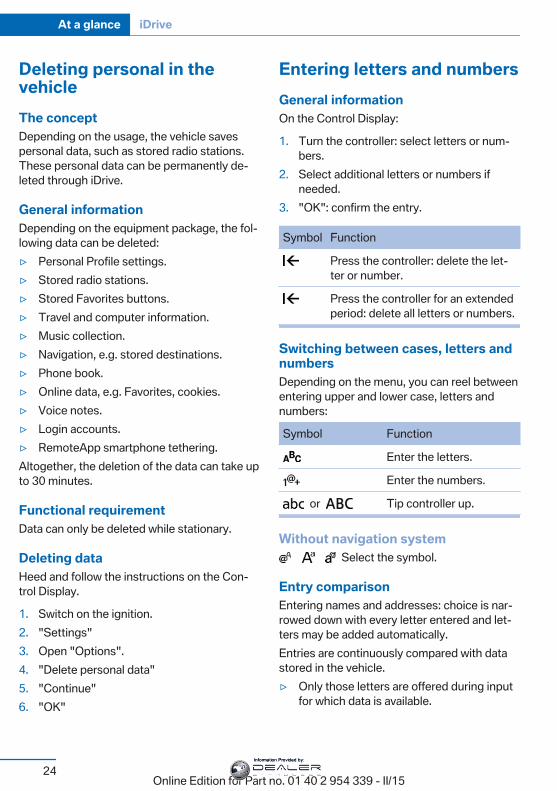
Entering letters and numbersGeneral informationOn the Control Display:
1. Turn the controller: select letters or num‐bers.
2. Select additional letters or numbers ifneeded.
3. "OK": confirm the entry.
Symbol Function
Press the controller: delete the let‐ter or number.
Press the controller for an extendedperiod: delete all letters or numbers.
Switching between cases, letters andnumbersDepending on the menu, you can reel betweenentering upper and lower case, letters andnumbers:
Symbol Function
Enter the letters.
Enter the numbers.
or Tip controller up.
Without navigation system Select the symbol.
Entry comparisonEntering names and addresses: choice is nar‐rowed down with every letter entered and let‐ters may be added automatically.Entries are continuously compared with datastored in the vehicle.▷ Only those letters are offered during input
for which data is available.
Seite 24
At a glance iDrive
24Online Edition for Part no. 01 40 2 954 339 - II/15
Information Provided by:

▷ Target search: names of locations may beentered in languages available throughControl Display.
Seite 25
iDrive At a glance
25Online Edition for Part no. 01 40 2 954 339 - II/15
Information Provided by:
Voice activation systemVehicle features and optionsThis chapter describes all standard, country-specific and optional features offered with theseries. It also describes features that are notnecessarily available in your car, e. g., due tothe selected options or country versions. Thisalso applies to safety-related functions andsystems. The respectively applicable countryprovisions must be observed when using therespective features and systems.
The concept▷ Most functions displayed on the Control
Display can be operated by voice com‐mands via the voice activation system. Thesystem supports you with announcementsduring input.
▷ Functions that can only be used when thevehicle is stationary cannot be used via thevoice activation system.
▷ The system uses a special microphone onthe driver's side.
▷ ›...‹ Verbal instructions in the Owner'sManual to use with the voice activationsystem.
RequirementsVia the Control Display, set a language that isalso supported by the voice activation systemso that the spoken commands can be identi‐fied.Set the language, refer to page 96.
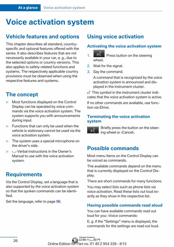
Using voice activationActivating the voice activation system
1. Press button on the steeringwheel.
2. Wait for the signal.3. Say the command.
A command that is recognized by the voiceactivation system is announced and dis‐played in the instrument cluster.
This symbol in the instrument cluster indi‐cates that the voice activation system is active.If no other commands are available, use func‐tion via iDrive.
Terminating the voice activationsystem
Briefly press the button on the steer‐ing wheel or ›Cancel‹.
Possible commandsMost menu items on the Control Display canbe voiced as commands.The available commands depend on the menuthat is currently displayed on the Control Dis‐play.There are short commands for many functions.You may select lists such as phone lists viavoice activation. Read these lists out loud ex‐actly as they show in the respective list.
Having possible commands read aloudYou can have available commands read outloud for you: ›Voice commands‹E. g. if the "Settings" menu is displayed, thecommands for the settings are read out loud.
Seite 26
At a glance Voice activation system
26Online Edition for Part no. 01 40 2 954 339 - II/15
Information Provided by:
Executing functions using shortcommandsExecute functions on the main menu via shortcommands. It almost doesn't matter whichmenu item is selected, e.g., ›Vehicle status‹.List of short commands for the voice activationsystem, see Navigation, Entertainment, Com‐munication Owner's Manual.
Help dialog for the voice activationsystemCalling up help dialog: ›Help‹Additional commands for the help dialog:▷ ›Help with examples‹: announces informa‐
tion about the current operating optionsand the most important commands forthem.
▷ ›Help with voice activation‹: informationabout the principle of operation for thevoice activation system is announced.
One example: open the tonesettingsVia the main menuThe commands of the menu items are spokenjust as they are selected via the controller.
1. Turn on the Entertainment sound output ifneeded.
2. Press button on the steeringwheel.
3. ›Radio‹4. ›Tone‹
Via short commandThe desired tone settings can also be startedvia a short command.
1. Turn on the Entertainment sound output ifneeded.
2. Press button on the steeringwheel.
3. ›Tone‹
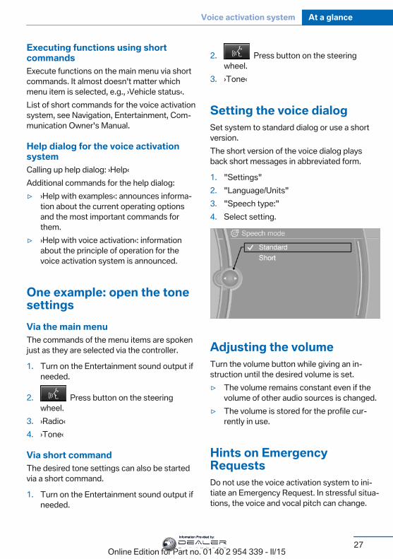
Setting the voice dialogSet system to standard dialog or use a shortversion.The short version of the voice dialog playsback short messages in abbreviated form.
1. "Settings"2. "Language/Units"3. "Speech type:"4. Select setting.
Adjusting the volumeTurn the volume button while giving an in‐struction until the desired volume is set.▷ The volume remains constant even if the
volume of other audio sources is changed.▷ The volume is stored for the profile cur‐
rently in use.
Hints on EmergencyRequestsDo not use the voice activation system to ini‐tiate an Emergency Request. In stressful situa‐tions, the voice and vocal pitch can change.
Seite 27
Voice activation system At a glance
27Online Edition for Part no. 01 40 2 954 339 - II/15
Information Provided by:
This can unnecessarily delay the establish‐ment of a phone connection.Instead, use the SOS button, refer topage 210, close to the interior mirror.
Environmental conditions▷ Say the commands, numbers, and letters
smoothly and with normal volume, empha‐sis, and speed.
▷ Always say commands in the language ofthe voice activation system.
▷ Keep the doors, windows, and glass sun‐roof closed to prevent noise interference.
▷ Avoid making other noise in the vehiclewhile speaking.
Seite 28
At a glance Voice activation system
28Online Edition for Part no. 01 40 2 954 339 - II/15
Information Provided by:
Integrated Owner's Manual in the vehicleVehicle features and optionsThis chapter describes all standard, country-specific and optional features offered with theseries. It also describes features that are notnecessarily available in your car, e. g., due tothe selected options or country versions. Thisalso applies to safety-related functions andsystems. The respectively applicable countryprovisions must be observed when using therespective features and systems.
Integrated Owner's Manualin the vehicleThe Integrated Owner's Manual can be dis‐played on the Control Display. It specificallydescribes features and functions found in thevehicle.
Components of the IntegratedOwner's ManualThe Integrated Owner's Manual consists ofthree parts, which offer various levels of infor‐mation or possible access.
Quick Reference GuideThe Quick Reference Guide provides informa‐tion how to operate the car, how to use basicvehicle functions or what to do in case of abreakdown. This information can also be dis‐played while driving.
Search by imagesImage search provides information and de‐scriptions. This is helpful when the terminol‐ogy for a feature is not at hand.
Owner's ManualSearch for information and descriptions by en‐tering terms selected from the index.
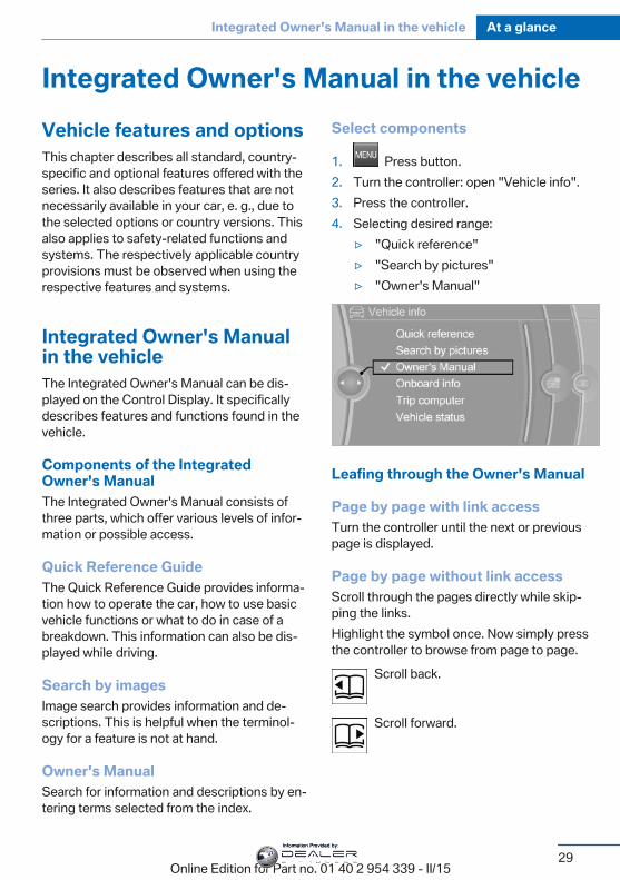
Select components
1. Press button.2. Turn the controller: open "Vehicle info".3. Press the controller.4. Selecting desired range:
▷ "Quick reference"▷ "Search by pictures"▷ "Owner's Manual"
Leafing through the Owner's Manual
Page by page with link accessTurn the controller until the next or previouspage is displayed.
Page by page without link accessScroll through the pages directly while skip‐ping the links.Highlight the symbol once. Now simply pressthe controller to browse from page to page.
Scroll back.
Scroll forward.
Seite 29
Integrated Owner's Manual in the vehicle At a glance
29Online Edition for Part no. 01 40 2 954 339 - II/15
Information Provided by:
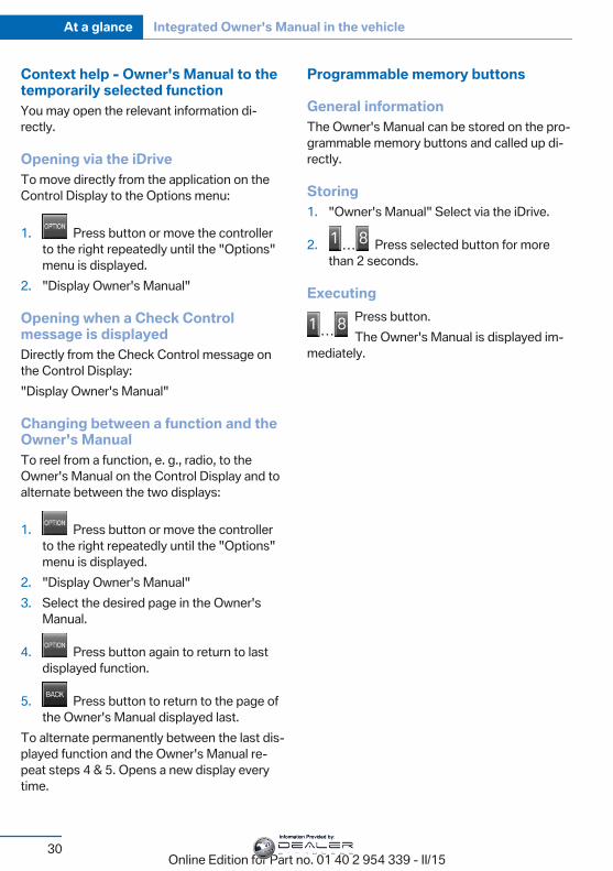
Context help - Owner's Manual to thetemporarily selected functionYou may open the relevant information di‐rectly.
Opening via the iDriveTo move directly from the application on theControl Display to the Options menu:
1. Press button or move the controllerto the right repeatedly until the "Options"menu is displayed.
2. "Display Owner's Manual"
Opening when a Check Controlmessage is displayedDirectly from the Check Control message onthe Control Display:"Display Owner's Manual"
Changing between a function and theOwner's ManualTo reel from a function, e. g., radio, to theOwner's Manual on the Control Display and toalternate between the two displays:
1. Press button or move the controllerto the right repeatedly until the "Options"menu is displayed.
2. "Display Owner's Manual"3. Select the desired page in the Owner's
Manual.
4. Press button again to return to lastdisplayed function.
5. Press button to return to the page ofthe Owner's Manual displayed last.
To alternate permanently between the last dis‐played function and the Owner's Manual re‐peat steps 4 & 5. Opens a new display everytime.
Programmable memory buttons
General informationThe Owner's Manual can be stored on the pro‐grammable memory buttons and called up di‐rectly.
Storing1. "Owner's Manual" Select via the iDrive.
2. Press selected button for morethan 2 seconds.
ExecutingPress button.The Owner's Manual is displayed im‐
mediately.
Seite 30
At a glance Integrated Owner's Manual in the vehicle
30Online Edition for Part no. 01 40 2 954 339 - II/15
Information Provided by:

Seite 31
Integrated Owner's Manual in the vehicle At a glance
31Online Edition for Part no. 01 40 2 954 339 - II/15
Information Provided by:
Online Edition for Part no. 01 40 2 954 339 - II/15
Information Provided by:
ControlsThis chapter is intended to provide you with
information that will give you complete control ofyour vehicle. All features and accessories thatare useful for driving and your safety, comfort
and convenience are described here.
Online Edition for Part no. 01 40 2 954 339 - II/15
Information Provided by:
Opening and closingVehicle features and optionsThis chapter describes all standard, country-specific and optional features offered with theseries. It also describes features that are notnecessarily available in your car, e. g., due tothe selected options or country versions. Thisalso applies to safety-related functions andsystems. The respectively applicable countryprovisions must be observed when using therespective features and systems.
Remote control/keyGeneral informationThe vehicle is supplied with two remote con‐trols with integrated key.Every remote control holds a replaceable bat‐tery.You may set the key functions depending onthe optional features and country-specific ver‐sion. For Settings, refer to page 46.The vehicle stores personal settings for everyremote control. Personal Profile, refer topage 35.The remote controls hold information on re‐quired maintenance. Service data in the re‐mote control, refer to page 201
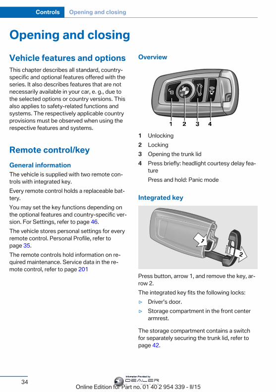
Overview
1 Unlocking2 Locking3 Opening the trunk lid4 Press briefly: headlight courtesy delay fea‐
turePress and hold: Panic mode
Integrated key
Press button, arrow 1, and remove the key, ar‐row 2.The integrated key fits the following locks:▷ Driver's door.▷ Storage compartment in the front center
armrest.
The storage compartment contains a switchfor separately securing the trunk lid, refer topage 42.
Seite 34
Controls Opening and closing
34Online Edition for Part no. 01 40 2 954 339 - II/15
Information Provided by:
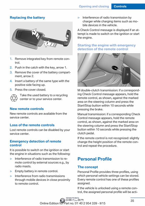
Replacing the battery
1. Remove integrated key from remote con‐trol.
2. Push in the catch with the key, arrow 1.3. Remove the cover of the battery compart‐
ment, arrow 2.4. Insert a battery of the same type with the
positive side facing up.5. Press the cover closed.
Take the used battery to a recyclingcenter or to your service center.
New remote controlsNew remote controls are available from theservice center.
Loss of the remote controlsLost remote controls can be disabled by yourservice center.
Emergency detection of remotecontrolIt is possible to switch on the ignition or startthe engine in situations such as the following:▷ Interference of radio transmission to re‐
mote control by external sources e.g., byradio masts.
▷ Empty battery in remote control.▷ Interference from radio transmissions
through mobile devices in close proximityto remote control.
▷ Interference of radio transmission bycharger while charging items such as mo‐bile devices in the vehicle.
A Check Control message is displayed if an at‐tempt is made to switch on the ignition or startthe engine.
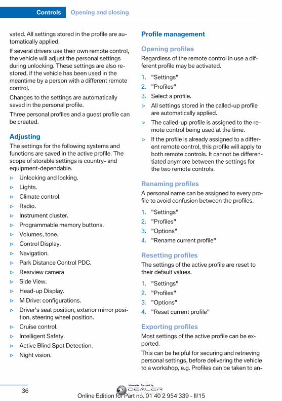
Starting the engine with emergencydetection of the remote control
M double-clutch transmission: if a correspond‐ing Check Control message appears, hold theremote control, as shown, against the markedarea on the steering column and press theStart/Stop button within 10 seconds whilepressing the brake.Manual transmission: if a corresponding CheckControl message appears, hold the remotecontrol, as shown, against the marked area onthe steering column and press the Start/Stopbutton within 10 seconds while pressing theclutch pedal.If the remote control is not recognized: slightlychange the height position of the remote con‐trol and repeat the procedure.
Personal ProfileThe conceptPersonal Profile provides three profiles, usingwhich personal vehicle settings can be stored.Every remote control has one of these profilesassigned.If the vehicle is unlocked using a remote con‐trol, the assigned personal profile will be acti‐
Seite 35
Opening and closing Controls
35Online Edition for Part no. 01 40 2 954 339 - II/15
Information Provided by:
vated. All settings stored in the profile are au‐tomatically applied.If several drivers use their own remote control,the vehicle will adjust the personal settingsduring unlocking. These settings are also re‐stored, if the vehicle has been used in themeantime by a person with a different remotecontrol.Changes to the settings are automaticallysaved in the personal profile.Three personal profiles and a guest profile canbe created.
AdjustingThe settings for the following systems andfunctions are saved in the active profile. Thescope of storable settings is country- andequipment-dependable.▷ Unlocking and locking.▷ Lights.▷ Climate control.▷ Radio.▷ Instrument cluster.▷ Programmable memory buttons.▷ Volumes, tone.▷ Control Display.▷ Navigation.▷ Park Distance Control PDC.▷ Rearview camera▷ Side View.▷ Head-up Display.▷ M Drive: configurations.▷ Driver's seat position, exterior mirror posi‐
tion, steering wheel position.▷ Cruise control.▷ Intelligent Safety.▷ Active Blind Spot Detection.▷ Night vision.
Profile management
Opening profilesRegardless of the remote control in use a dif‐ferent profile may be activated.
1. "Settings"2. "Profiles"3. Select a profile.▷ All settings stored in the called-up profile
are automatically applied.▷ The called-up profile is assigned to the re‐
mote control being used at the time.▷ If the profile is already assigned to a differ‐
ent remote control, this profile will apply toboth remote controls. It cannot be differen‐tiated anymore between the settings forthe two remote controls.
Renaming profilesA personal name can be assigned to every pro‐file to avoid confusion between the profiles.
1. "Settings"2. "Profiles"3. "Options"4. "Rename current profile"
Resetting profilesThe settings of the active profile are reset totheir default values.
1. "Settings"2. "Profiles"3. "Options"4. "Reset current profile"
Exporting profilesMost settings of the active profile can be ex‐ported.This can be helpful for securing and retrievingpersonal settings, before delivering the vehicleto a workshop, e.g. Profiles can be taken to an‐
Seite 36
Controls Opening and closing
36Online Edition for Part no. 01 40 2 954 339 - II/15
Information Provided by:
other vehicle equipped with the Personal Pro‐file function.The following export options are available:▷ Via BMW Online.▷ Via the USB port to a USB device.
Popular file systems for USB devices aresupported. FAT32 and exFAT are the rec‐ommended formats for profile export.Other formats may not support the export.
1. "Settings"2. "Profiles"3. "Export profile"4. BMW Online: "BMW Online"
USB interface: "USB device"
Importing profilesProfiles exported via BMW Online can also beimported via BMW Online.Profiles stored on a USB device can be im‐ported via the USB interface.Existing settings are overwritten with the im‐ported profile.
1. "Settings"2. "Profiles"3. "Import profile"4. BMW Online: "BMW Online"
USB interface: "USB device"
Using the guest profileThe guest profile is for individual settings thatare saved in none of the three personal pro‐files.This can be useful for drivers who are usingthe vehicle temporarily and do not have theirown profile.
1. "Settings"2. "Profiles"3. "Guest"The guest profile cannot be renamed. It is notassigned to the current remote control.
Display profile list during startThe profile list can be displayed during eachstart to select the desired profile.
1. "Settings"2. "Profiles"3. "Options"4. "Display user list at startup"
Using the remote controlNote
Take the remote control with youPeople or animals left unattended in a
parked vehicle can lock the doors from the in‐side. Always take the remote control with youwhen leaving the vehicle so that the vehiclecan then be opened from the outside.◀
UnlockingPress button on the remote control.
▷ All doors, the tailgate, and the fuel filler flapare being unlocked.
▷ Interior lamps and courtesy lamps are acti‐vated. This function is not available, if theinterior lamps were switched off manually.
▷ The welcome lamps are switched on, if thisfunction was activated.
▷ Exterior mirrors folded through convenientclosing are folded open.
You can set how the vehicle is to be unlocked.For Settings, refer to page 46.Anti-theft protection is switched off.The alarm system, refer to page 47, is dis‐armed.
Convenient openingPress and hold this button on the re‐mote control after unlocking.
Seite 37
Opening and closing Controls
37Online Edition for Part no. 01 40 2 954 339 - II/15
Information Provided by:
The windows and the glass sunroof areopened, as long as the button on the remotecontrol is pressed.
LockingLocking from the outsideDo not lock the vehicle from the outside
with people inside the car, as the vehicle can‐not be unlocked from inside without specialknowledge.◀
The driver's door must be closed.Press button on the remote control.
All doors, the tailgate, and the fuel filler flap arebeing locked.Anti-theft protection is switched on. It pre‐vents the doors from being unlocked using thelock buttons or the door openers.The alarm system, refer to page 47, is armed.
Switching on interior lights andcourtesy lights
Press button on the remote control withthe vehicle locked.
This function is not available, if the interiorlamps were switched off manually.If the button is pressed again within 10 sec‐onds after vehicle was locked, the interior mo‐tion sensor and tilt alarm sensor of the anti-theft warning system, refer to page 48, areturned off. After locking, wait 10 seconds be‐fore pressing the button again.
Panic modeYou can trigger the alarm system if you findyourself in a dangerous situation.
Press button on the remote control forat least 3 seconds.
To reel off the alarm: press any button.
Opening the trunk lidPress button on the remote control forapprox. 1 second.
The trunk lid opens, regardless of whether thevehicle was previously locked or unlocked.During opening, the trunk lid pivots back andup. Ensure that adequate clearance is availablebefore opening.Depending on the features and the countryversion, it is also possible to have door un‐locked. Create the settings, refer to page 46.If the doors were not unlocked, the trunk lid islocked again as soon as it closes.
Do not place the remote control in thecargo area
Take the remote control with you and do notleave it in the cargo area; otherwise, the re‐mote control is locked inside the vehicle whenthe trunk lid is closed.◀
Switching on the headlight courtesydelay feature
Briefly press the button on the remotecontrol.
The duration can be set in the Control Display.
MalfunctionRemote control detection by the vehicle canamong others be malfunctioning under the fol‐lowing circumstances:▷ The battery of the remote control is dis‐
charged. Replace the battery, refer topage 35.
▷ Interference of the radio connection fromtransmission towers or other equipmentwith high transmit power.
▷ Shielding of the remote control due tometal objects.
▷ Interference of the radio connection frommobile phones or other electronic devicesin direct proximity.
Seite 38
Controls Opening and closing
38Online Edition for Part no. 01 40 2 954 339 - II/15
Information Provided by:
Do not transport the remote control togetherwith metal objects or electronic devices.In the case of interference, the vehicle can alsobe unlocked and locked from the outside with‐out remote control, refer to page 39.
For US owners onlyThe transmitter and receiver units comply withpart 15 of the FCC/Federal CommunicationCommission regulations. Operation is gov‐erned by the following:FCC ID:▷ LX8766S.▷ LX8766E.▷ LX8CAS.▷ LX8CAS2.▷ MYTCAS4.Compliance statement:This device complies with part 15 of the FCCRules. Operation is subject to the followingtwo conditions:▷ This device may not cause harmful inter‐
ference, and▷ this device must accept any interference
received, including interference that maycause undesired operation.
Any unauthorized modifications or changes tothese devices could void the user's authority tooperate this equipment.
Without remote controlFrom the outside
Locking from the outsideDo not lock the vehicle from the outside
with people inside the car, as the vehicle can‐not be unlocked from inside without specialknowledge.◀
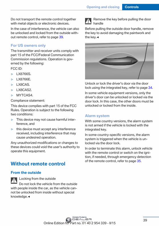
Remove the key before pulling the doorhandle
Before pulling the outside door handle, removethe key to avoid damaging the paintwork andthe key.◀
Unlock or lock the driver's door via the doorlock using the integrated key, refer to page 34.In some vehicle equipment versions, only thedriver's door can be unlocked or locked via thedoor lock. In this case, the other doors must beunlocked or locked from the inside.
Alarm systemWith some country versions, the alarm systemis not armed if the vehicle is locked with theintegrated key.In some country-specific versions, the alarmsystem is triggered when the vehicle is un‐locked via the door lock.In order to terminate this alarm, unlock vehiclewith the remote control or switch on the igni‐tion, if needed, through emergency detectionof the remote control, refer to page 35.
Seite 39
Opening and closing Controls
39Online Edition for Part no. 01 40 2 954 339 - II/15
Information Provided by:
From the inside
Unlocking and locking
Pressing the central locking system buttonlocks or unlocks the vehicle with the frontdoors closed.
The vehicle is not secured against theft whenlocking.The fuel filler flap remains unlocked.In the event of a severe accident, the vehicle isautomatically unlocked. The hazard warningsystem and interior lights come on.
Unlocking and opening
▷ Press the central locking system button tounlock the doors together, and then pullthe door handle above the armrest.
▷ On the door to be opened, pull the doorhandle twice: the first time unlocks thedoor, the second time opens it. The otherdoors remain locked.
DoorsAutomatic Soft ClosingTo close the doors, push lightly.It is closed automatically.
Danger of jammingMake sure that the closing path of the
doors is clear; otherwise, injuries may result.◀
Trunk lidOpeningDuring opening, the trunk lid pivots back andup.Ensure that adequate clearance is availablebefore opening.
Opening from the outside
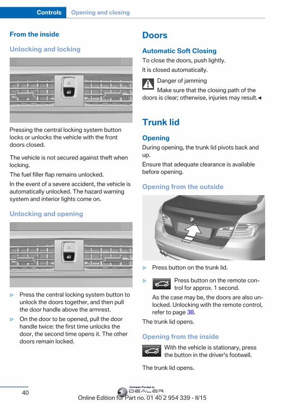
▷ Press button on the trunk lid.
▷ Press button on the remote con‐trol for approx. 1 second.
As the case may be, the doors are also un‐locked. Unlocking with the remote control,refer to page 38.
The trunk lid opens.
Opening from the insideWith the vehicle is stationary, pressthe button in the driver's footwell.
The trunk lid opens.
Seite 40
Controls Opening and closing
40Online Edition for Part no. 01 40 2 954 339 - II/15
Information Provided by:
Locking and closing
HintsKeep the closing path clearMake sure that the closing path of the
trunk lid is clear; otherwise, injuries may re‐sult.◀
Do not place the remote control in thecargo area
Take the remote control with you and do notleave it in the cargo area; otherwise, the re‐mote control is locked inside the vehicle whenthe trunk lid is closed.◀
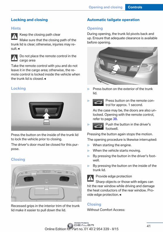
Locking
Press the button on the inside of the trunk lidto lock the vehicle prior to closing.The driver's door must be closed for this pur‐pose.
Closing
Recessed grips in the interior trim of the trunklid make it easier to pull down the lid.
Automatic tailgate operation
OpeningDuring opening, the trunk lid pivots back andup. Ensure that adequate clearance is availablebefore opening.
▷ Press button on the exterior of the trunklid.
▷ Press button on the remote con‐trol for approx. 1 second.
As the case may be, the doors are also un‐locked. Opening with the remote control,refer to page 38.
▷ Push the button in the driver'sfootwell.
Pressing the button again stops the motion.The opening procedure is likewise interrupted:▷ When starting the engine.▷ When the vehicle starts moving.▷ By pressing the button in the driver's foot‐
well.▷ By pressing the button on the inside of the
trunk lid.Provide edge protectionSharp objects or those with edges can
hit the rear window while driving and damagethe heat conductors of the rear window. Pro‐vide edge protection.◀
ClosingWithout Comfort Access:
Seite 41
Opening and closing Controls
41Online Edition for Part no. 01 40 2 954 339 - II/15
Information Provided by:
▷ Press button on the inside of the trunk lid.The trunk lid closes automatically.Pressing the button again stops the mo‐tion.
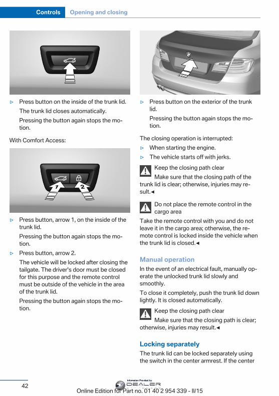
With Comfort Access:
▷ Press button, arrow 1, on the inside of thetrunk lid.Pressing the button again stops the mo‐tion.
▷ Press button, arrow 2.The vehicle will be locked after closing thetailgate. The driver's door must be closedfor this purpose and the remote controlmust be outside of the vehicle in the areaof the trunk lid.Pressing the button again stops the mo‐tion.
▷ Press button on the exterior of the trunklid.Pressing the button again stops the mo‐tion.
The closing operation is interrupted:▷ When starting the engine.▷ The vehicle starts off with jerks.
Keep the closing path clearMake sure that the closing path of the
trunk lid is clear; otherwise, injuries may re‐sult.◀
Do not place the remote control in thecargo area
Take the remote control with you and do notleave it in the cargo area; otherwise, the re‐mote control is locked inside the vehicle whenthe trunk lid is closed.◀
Manual operationIn the event of an electrical fault, manually op‐erate the unlocked trunk lid slowly andsmoothly.To close it completely, push the trunk lid downlightly. It is closed automatically.
Keep the closing path clearMake sure that the closing path is clear;
otherwise, injuries may result.◀
Locking separatelyThe trunk lid can be locked separately usingthe switch in the center armrest. If the center
Seite 42
Controls Opening and closing
42Online Edition for Part no. 01 40 2 954 339 - II/15
Information Provided by:
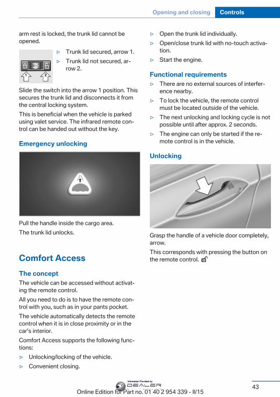
arm rest is locked, the trunk lid cannot beopened.
▷ Trunk lid secured, arrow 1.▷ Trunk lid not secured, ar‐
row 2.
Slide the switch into the arrow 1 position. Thissecures the trunk lid and disconnects it fromthe central locking system.This is beneficial when the vehicle is parkedusing valet service. The infrared remote con‐trol can be handed out without the key.
Emergency unlocking
Pull the handle inside the cargo area.The trunk lid unlocks.
Comfort AccessThe conceptThe vehicle can be accessed without activat‐ing the remote control.All you need to do is to have the remote con‐trol with you, such as in your pants pocket.The vehicle automatically detects the remotecontrol when it is in close proximity or in thecar's interior.Comfort Access supports the following func‐tions:▷ Unlocking/locking of the vehicle.▷ Convenient closing.
▷ Open the trunk lid individually.▷ Open/close trunk lid with no-touch activa‐
tion.▷ Start the engine.
Functional requirements▷ There are no external sources of interfer‐
ence nearby.▷ To lock the vehicle, the remote control
must be located outside of the vehicle.▷ The next unlocking and locking cycle is not
possible until after approx. 2 seconds.▷ The engine can only be started if the re‐
mote control is in the vehicle.
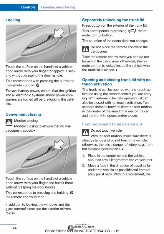
Unlocking
Grasp the handle of a vehicle door completely,arrow.This corresponds with pressing the button onthe remote control.
Seite 43
Opening and closing Controls
43Online Edition for Part no. 01 40 2 954 339 - II/15
Information Provided by:
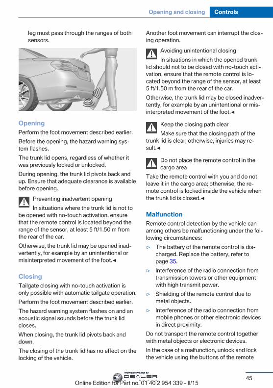
Locking
Touch the surface on the handle of a vehicledoor, arrow, with your finger for approx. 1 sec‐ond without grasping the door handle.This corresponds with pressing the button onthe remote control. To save battery power, ensure that the ignitionand all electronic systems and/or power con‐sumers are turned off before locking the vehi‐cle.
Convenient closingMonitor closingMonitor closing to ensure that no one
becomes trapped.◀
Touch the surface on the handle of a vehicledoor, arrow, with your finger and hold it therewithout grasping the door handle.This corresponds to pressing and holding the remote control button.
In addition to locking, the windows and theglass sunroof close and the exterior mirrorsfold in.
Separately unlocking the trunk lidPress button on the exterior of the trunk lid.This corresponds to pressing the re‐mote control button.The situation of the doors does not change.
Do not place the remote control in thecargo area
Take the remote control with you and do notleave it in the cargo area; otherwise, the re‐mote control is locked inside the vehicle whenthe trunk lid is closed.◀
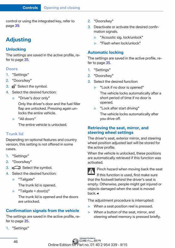
Opening and closing trunk lid with no-touch activationThe trunk lid can be opened with no-touch ac‐tivation using the remote control you are carry‐ing. With automatic tailgate operation, it canalso be closed with no-touch activation. Twosensors detect a forward-directed foot motionin the center of the area at the rear of the carand the trunk lid opens and/or closes.
Foot movement to be carried outDo not touch vehicleWith the foot motion, make sure there is
steady stance and do not touch the vehicle;otherwise, there is a danger of injury, e. g. fromhot exhaust system parts.◀
1. Place in the center behind the vehicle,about an arm's length from the vehicle rear.
2. Move a foot in the direction of travel as farunder the vehicle as possible and immedi‐ately pull it back. With this movement, the
Seite 44
Controls Opening and closing
44Online Edition for Part no. 01 40 2 954 339 - II/15
Information Provided by:
leg must pass through the ranges of bothsensors.
OpeningPerform the foot movement described earlier.Before the opening, the hazard warning sys‐tem flashes.The trunk lid opens, regardless of whether itwas previously locked or unlocked.During opening, the trunk lid pivots back andup. Ensure that adequate clearance is availablebefore opening.
Preventing inadvertent openingIn situations where the trunk lid is not to
be opened with no-touch activation, ensurethat the remote control is located beyond therange of the sensor, at least 5 ft/1.50 m fromthe rear of the car.Otherwise, the trunk lid may be opened inad‐vertently, for example by an unintentional ormisinterpreted movement of the foot.◀
ClosingTailgate closing with no-touch activation isonly possible with automatic tailgate operation.Perform the foot movement described earlier.The hazard warning system flashes on and anacoustic signal sounds before the trunk lidcloses.When closing, the trunk lid pivots back anddown.The closing of the trunk lid has no effect on thelocking of the vehicle.
Another foot movement can interrupt the clos‐ing operation.
Avoiding unintentional closingIn situations in which the opened trunk
lid should not to be closed with no-touch acti‐vation, ensure that the remote control is lo‐cated beyond the range of the sensor, at least5 ft/1.50 m from the rear of the car.Otherwise, the trunk lid may be closed inadver‐tently, for example by an unintentional or mis‐interpreted movement of the foot.◀
Keep the closing path clearMake sure that the closing path of the
trunk lid is clear; otherwise, injuries may re‐sult.◀
Do not place the remote control in thecargo area
Take the remote control with you and do notleave it in the cargo area; otherwise, the re‐mote control is locked inside the vehicle whenthe trunk lid is closed.◀
MalfunctionRemote control detection by the vehicle canamong others be malfunctioning under the fol‐lowing circumstances:▷ The battery of the remote control is dis‐
charged. Replace the battery, refer topage 35.
▷ Interference of the radio connection fromtransmission towers or other equipmentwith high transmit power.
▷ Shielding of the remote control due tometal objects.
▷ Interference of the radio connection frommobile phones or other electronic devicesin direct proximity.
Do not transport the remote control togetherwith metal objects or electronic devices.In the case of a malfunction, unlock and lockthe vehicle using the buttons of the remote
Seite 45
Opening and closing Controls
45Online Edition for Part no. 01 40 2 954 339 - II/15
Information Provided by:
control or using the integrated key, refer topage 39.
AdjustingUnlockingThe settings are saved in the active profile, re‐fer to page 35.
Doors1. "Settings"2. "Doors/key"3. Select the symbol.4. Select the desired function:
▷ "Driver's door only"Only the driver's door and the fuel fillerflap are unlocked. Pressing again un‐locks the entire vehicle.
▷ "All doors"The entire vehicle is unlocked.
Trunk lidDepending on optional features and countryversion, this setting is not offered in somecases.
1. "Settings"2. "Doors/key"3. Select the symbol.4. Select the desired function:
▷ "Tailgate"The trunk lid is opened.
▷ "Tailgate + door(s)"The trunk lid is opened and the doorsare unlocked.
Confirmation signals from the vehicleThe settings are saved in the active profile, re‐fer to page 35.
1. "Settings"
2. "Doors/key"3. Deactivate or activate the desired confir‐
mation signals.▷ "Acoustic sig. lock/unlock"▷ "Flash when lock/unlock"
Automatic lockingThe settings are saved in the active profile, re‐fer to page 35.
1. "Settings"2. "Doors/key"3. Select the desired function:
▷ "Lock if no door is opened"The vehicle locks automatically after ashort period of time if no door isopened.
▷ "Lock after start driving"The vehicle locks automatically afteryou drive off.
Retrieving the seat, mirror, andsteering wheel settingsThe driver's seat, exterior mirror, and steeringwheel position adjusted last will be stored forthe active profile.When the vehicle is unlocked, these positionsare automatically retrieved if this function wasactivated.
Pinch hazard when moving back the seatIf this function is used, first make sure
that the footwell behind the driver's seat isempty. Otherwise, people might get injured orobjects damaged when the seat is movedback.◀
The adjustment procedure is interrupted:▷ When a seat position reel is pressed.▷ When a button of the seat, mirror, and
steering wheel memory is pressed briefly.
Seite 46
Controls Opening and closing
46Online Edition for Part no. 01 40 2 954 339 - II/15
Information Provided by:
Activating the setting1. "Settings"2. "Doors/key"3. "Last seat position autom."
Alarm systemThe conceptWhen the vehicle is locked, the vehicle alarmsystem responds to:▷ Opening a door, the hood or the trunk lid.▷ Movements in the interior.▷ Changes in the vehicle tilt, e. g., during at‐
tempts at stealing a wheel or when towingthe car.
▷ Disconnected battery voltage.The alarm system briefly signals tampering:▷ By sounding an acoustic alarm.▷ By switching on the hazard warning sys‐
tem.▷ By flashing the daytime running lights.
Arming and disarming the alarmsystemWhen you unlock or lock the vehicle, eitherwith the remote control, Comfort Access or atthe door lock the alarm system is disarmed orarmed at the same time.
Door lock and armed alarm systemUnlocking via the door lock will trigger thealarm on some country-specific versions.
Trunk lid and armed alarm systemThe trunk lid can be opened even when thealarm system is armed.After the trunk lid is closed, it is locked andmonitored again when the doors are locked.The hazard warning system flashes once.
Panic modeYou can trigger the alarm system if you findyourself in a dangerous situation.
Press button on the remote control forat least 3 seconds.
To switch off the alarm: press any button.
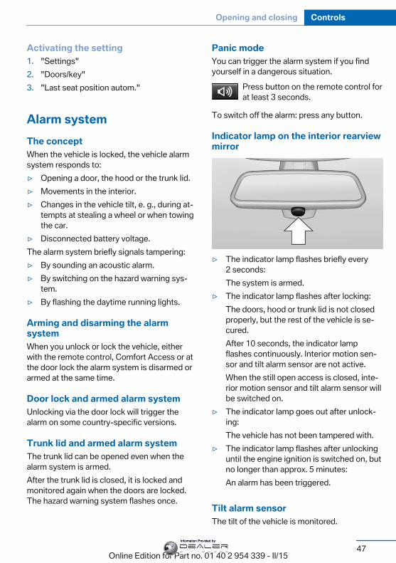
Indicator lamp on the interior rearviewmirror
▷ The indicator lamp flashes briefly every2 seconds:The system is armed.
▷ The indicator lamp flashes after locking:The doors, hood or trunk lid is not closedproperly, but the rest of the vehicle is se‐cured.After 10 seconds, the indicator lampflashes continuously. Interior motion sen‐sor and tilt alarm sensor are not active.When the still open access is closed, inte‐rior motion sensor and tilt alarm sensor willbe switched on.
▷ The indicator lamp goes out after unlock‐ing:The vehicle has not been tampered with.
▷ The indicator lamp flashes after unlockinguntil the engine ignition is switched on, butno longer than approx. 5 minutes:An alarm has been triggered.
Tilt alarm sensorThe tilt of the vehicle is monitored.
Seite 47
Opening and closing Controls
47Online Edition for Part no. 01 40 2 954 339 - II/15
Information Provided by:
The alarm system responds in situations suchas attempts to steal a wheel or when the car istowed.
Interior motion sensorThe windows and glass sunroof must beclosed for the system to function properly.
Avoiding unintentional alarmsThe tilt alarm sensor and interior motion sen‐sor can be switched off together, such as inthe following situations:▷ In automatic car washes.▷ In duplex garages.▷ During transport on trains carrying vehi‐
cles, at sea or on a trailer.▷ With animals in the vehicle.
Switching off the tilt alarm sensor andinterior motion sensor
Press the remote control button againwithin 10 seconds as soon as the vehicle
is locked.The indicator lamp lights up for approx. 2 sec‐onds and then continues to flash.The tilt alarm sensor and interior motion sen‐sor are turned off, until the vehicle is lockedagain.
Switching off the alarm▷ Unlock vehicle with the remote control or
switch on the ignition, if needed throughemergency detection of remote control, re‐fer to page 35.
▷ With Comfort Access: if you are carryingthe remote control on your person, graspthe driver side or front passenger side doorhandle completely.
Power windowsHint
Take the remote control with youTake the remote control with you when
leaving the vehicle so that children, e.g., can‐not operate the power windows and injurethemselves.◀
Opening
▷ Press the button to the resistancepoint.The window opens while the switch is held.
▷ Press the switch beyond the resist‐ance point.The window opens automatically. Pressingthe switch again stopse the motion.
See also: Convenient opening, refer topage 37, via remote control.
ClosingKeep the closing path clearMonitor closing and make sure that the
closing path of the window is clear; otherwise,injuries may result.◀
▷ Pull the switch to the resistancepoint.The window closes while the switch isheld.
Seite 48
Controls Opening and closing
48Online Edition for Part no. 01 40 2 954 339 - II/15
Information Provided by:
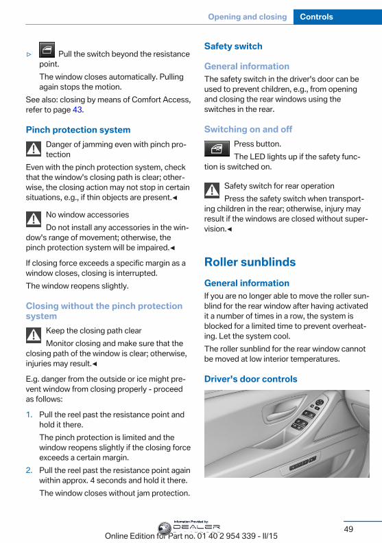
▷ Pull the switch beyond the resistancepoint.The window closes automatically. Pullingagain stops the motion.
See also: closing by means of Comfort Access,refer to page 43.
Pinch protection systemDanger of jamming even with pinch pro‐tection
Even with the pinch protection system, checkthat the window's closing path is clear; other‐wise, the closing action may not stop in certainsituations, e.g., if thin objects are present.◀
No window accessoriesDo not install any accessories in the win‐
dow's range of movement; otherwise, thepinch protection system will be impaired.◀
If closing force exceeds a specific margin as awindow closes, closing is interrupted.The window reopens slightly.
Closing without the pinch protectionsystem
Keep the closing path clearMonitor closing and make sure that the
closing path of the window is clear; otherwise,injuries may result.◀
E.g. danger from the outside or ice might pre‐vent window from closing properly - proceedas follows:
1. Pull the reel past the resistance point andhold it there.The pinch protection is limited and thewindow reopens slightly if the closing forceexceeds a certain margin.
2. Pull the reel past the resistance point againwithin approx. 4 seconds and hold it there.The window closes without jam protection.
Safety switch
General informationThe safety switch in the driver's door can beused to prevent children, e.g., from openingand closing the rear windows using theswitches in the rear.
Switching on and offPress button.The LED lights up if the safety func‐
tion is switched on.
Safety switch for rear operationPress the safety switch when transport‐
ing children in the rear; otherwise, injury mayresult if the windows are closed without super‐vision.◀
Roller sunblindsGeneral informationIf you are no longer able to move the roller sun‐blind for the rear window after having activatedit a number of times in a row, the system isblocked for a limited time to prevent overheat‐ing. Let the system cool.The roller sunblind for the rear window cannotbe moved at low interior temperatures.
Driver's door controls
Seite 49
Opening and closing Controls
49Online Edition for Part no. 01 40 2 954 339 - II/15
Information Provided by:
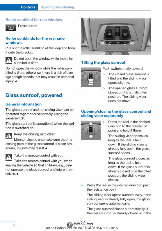
Roller sunblind for rear windowPress button.
Roller sunblinds for the rear sidewindowsPull out the roller sunblind at the loop and hookit onto the bracket.
Do not open the window while the rollersunblind is tilted
Do not open the window while the roller sun‐blind is tilted; otherwise, there is a risk of dam‐age at high speeds that may result in personalinjury.◀
Glass sunroof, poweredGeneral informationThe glass sunroof and the sliding visor can beoperated together or separately, using thesame switch.The glass sunroof is operational when the igni‐tion is switched on.
Keep the closing path clearMonitor closing and make sure that the
closing path of the glass sunroof is clear; oth‐erwise, injuries may result.◀
Take the remote control with youTake the remote control with you when
leaving the vehicle so that children, e.g., can‐not operate the glass sunroof and injure them‐selves.◀
Tilting the glass sunroofPush switch briefly upward.▷ The closed glass sunroof is
tilted and the sliding visoropens slightly.
▷ The opened glass sunroofcloses until it is in its tiltedposition. The sliding visordoes not move.
Opening/closing the glass sunroof andsliding visor separately
▷ Press the reel in the desireddirection to the resistancepoint and hold it there.The sliding visor opens, aslong as the reel is helddown. If the sliding visor isalready fully open, the glasssunroof opens.The glass sunroof closes aslong as the reel is helddown. If the glass sunroof isalready closed or in the tiltedposition, the sliding visorcloses.
▷ Press the reel in the desired direction pastthe resistance point.The sliding visor opens automatically. If thesliding visor is already fully open, the glasssunroof opens automatically.The glass sunroof closes automatically. Ifthe glass sunroof is already closed or in the
Seite 50
Controls Opening and closing
50Online Edition for Part no. 01 40 2 954 339 - II/15
Information Provided by:
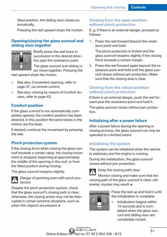
tilted position, the sliding visor closes au‐tomatically.Pressing the reel upward stops the motion.
Opening/closing the glass sunroof andsliding visor together
Briefly press the reel twice insuccession in the desired direc‐tion past the resistance point.The glass sunroof and sliding vi‐sor move together. Pressing the
reel upward stops the motion.
▷ See also: Convenient opening, refer topage 37, via remote control.
▷ See also: closing by means of Comfort Ac‐cess, refer to page 43.
Comfort positionIf the glass sunroof is not automatically com‐pletely opened, the comfort position has beenattained. In this position the wind noises in theinterior are the least.If desired, continue the movement by pressingthe reel.
Pinch protection systemIf the closing force when closing the glass sun‐roof exceeds a certain value, the closing move‐ment is stopped, beginning at approximatelythe middle of the opening in the roof, or fromthe tilted position during closing.The glass sunroof reopens slightly.
Danger of jamming even with pinch pro‐tection
Despite the pinch protection system, checkthat the glass sunroof's closing path is clear;otherwise, the closing action may not be inter‐rupted in certain extreme situations, such aswhen thin objects are present.◀
Closing from the open positionwithout pinch protectionE. g. if there is an external danger, proceed asfollows:
1. Press the reel forward beyond the resist‐ance point and hold.The pinch protection is limited and theglass sunroof reopens slightly if the closingforce exceeds a certain margin.
2. Press the reel forward again beyond the re‐sistance point and hold until the glass sun‐roof closes without jam protection. Makesure that the closing area is clear.
Closing from the raised positionwithout pinch protectionIf there is an external danger, push the reel for‐ward past the resistance point and hold it.The glass sunroof closes without jam protec‐tion.
Initializing after a power failureAfter a power failure during the opening orclosing process, the glass sunroof can only beoperated to a limited extent.
Initializing the systemThe system can be initialized when the vehicleis stationary and the engine is running.During the initialization, the glass sunroofcloses without jam protection.
Keep the closing path clearMonitor closing and make sure that the
closing path of the glass sunroof is clear; oth‐erwise, injuries may result.◀
Press the reel up and hold it untilthe initialization is complete:▷ Initialization begins within
15 seconds and is com‐pleted when the glass sun‐roof and sliding visor arecompletely closed.
Seite 51
Opening and closing Controls
51Online Edition for Part no. 01 40 2 954 339 - II/15
Information Provided by:

▷ The glass sunroof closes without jam pro‐tection.
Seite 52
Controls Opening and closing
52Online Edition for Part no. 01 40 2 954 339 - II/15
Information Provided by:
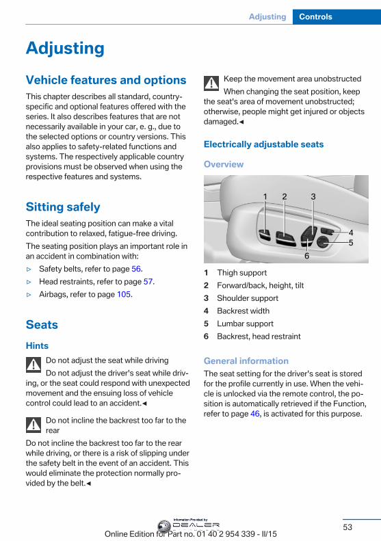
AdjustingVehicle features and optionsThis chapter describes all standard, country-specific and optional features offered with theseries. It also describes features that are notnecessarily available in your car, e. g., due tothe selected options or country versions. Thisalso applies to safety-related functions andsystems. The respectively applicable countryprovisions must be observed when using therespective features and systems.
Sitting safelyThe ideal seating position can make a vitalcontribution to relaxed, fatigue-free driving.The seating position plays an important role inan accident in combination with:▷ Safety belts, refer to page 56.▷ Head restraints, refer to page 57.▷ Airbags, refer to page 105.
SeatsHints
Do not adjust the seat while drivingDo not adjust the driver's seat while driv‐
ing, or the seat could respond with unexpectedmovement and the ensuing loss of vehiclecontrol could lead to an accident.◀
Do not incline the backrest too far to therear
Do not incline the backrest too far to the rearwhile driving, or there is a risk of slipping underthe safety belt in the event of an accident. Thiswould eliminate the protection normally pro‐vided by the belt.◀
Keep the movement area unobstructedWhen changing the seat position, keep
the seat's area of movement unobstructed;otherwise, people might get injured or objectsdamaged.◀
Electrically adjustable seats
Overview
1 Thigh support2 Forward/back, height, tilt3 Shoulder support4 Backrest width5 Lumbar support6 Backrest, head restraint
General informationThe seat setting for the driver's seat is storedfor the profile currently in use. When the vehi‐cle is unlocked via the remote control, the po‐sition is automatically retrieved if the Function,refer to page 46, is activated for this purpose.
Seite 53
Adjusting Controls
53Online Edition for Part no. 01 40 2 954 339 - II/15
Information Provided by:
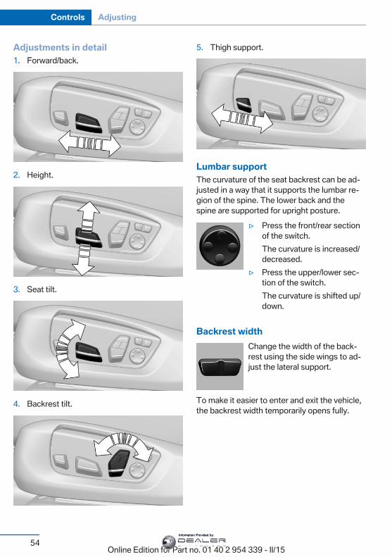
Adjustments in detail1. Forward/back.
2. Height.
3. Seat tilt.
4. Backrest tilt.
5. Thigh support.
Lumbar supportThe curvature of the seat backrest can be ad‐justed in a way that it supports the lumbar re‐gion of the spine. The lower back and thespine are supported for upright posture.
▷ Press the front/rear sectionof the switch.The curvature is increased/decreased.
▷ Press the upper/lower sec‐tion of the switch.The curvature is shifted up/down.
Backrest widthChange the width of the back‐rest using the side wings to ad‐just the lateral support.
To make it easier to enter and exit the vehicle,the backrest width temporarily opens fully.
Seite 54
Controls Adjusting
54Online Edition for Part no. 01 40 2 954 339 - II/15
Information Provided by:
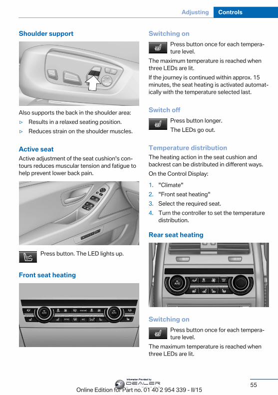
Shoulder support
Also supports the back in the shoulder area:▷ Results in a relaxed seating position.▷ Reduces strain on the shoulder muscles.
Active seatActive adjustment of the seat cushion's con‐tours reduces muscular tension and fatigue tohelp prevent lower back pain.
Press button. The LED lights up.
Front seat heating
Switching onPress button once for each tempera‐ture level.
The maximum temperature is reached whenthree LEDs are lit.If the journey is continued within approx. 15minutes, the seat heating is activated automat‐ically with the temperature selected last.
Switch offPress button longer.The LEDs go out.
Temperature distributionThe heating action in the seat cushion andbackrest can be distributed in different ways.On the Control Display:
1. "Climate"2. "Front seat heating"3. Select the required seat.4. Turn the controller to set the temperature
distribution.
Rear seat heating
Switching onPress button once for each tempera‐ture level.
The maximum temperature is reached whenthree LEDs are lit.
Seite 55
Adjusting Controls
55Online Edition for Part no. 01 40 2 954 339 - II/15
Information Provided by:
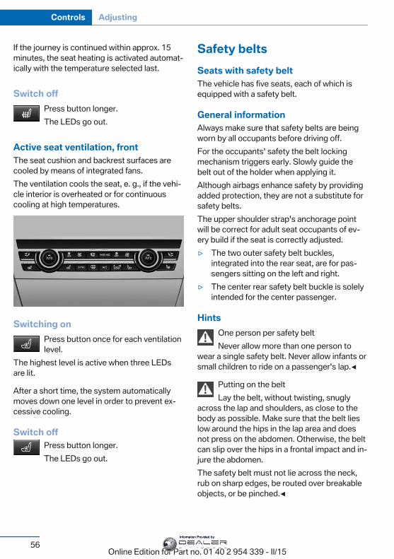
If the journey is continued within approx. 15minutes, the seat heating is activated automat‐ically with the temperature selected last.
Switch offPress button longer.The LEDs go out.
Active seat ventilation, frontThe seat cushion and backrest surfaces arecooled by means of integrated fans.The ventilation cools the seat, e. g., if the vehi‐cle interior is overheated or for continuouscooling at high temperatures.
Switching onPress button once for each ventilationlevel.
The highest level is active when three LEDsare lit.
After a short time, the system automaticallymoves down one level in order to prevent ex‐cessive cooling.
Switch offPress button longer.The LEDs go out.
Safety beltsSeats with safety beltThe vehicle has five seats, each of which isequipped with a safety belt.
General informationAlways make sure that safety belts are beingworn by all occupants before driving off.For the occupants' safety the belt lockingmechanism triggers early. Slowly guide thebelt out of the holder when applying it.Although airbags enhance safety by providingadded protection, they are not a substitute forsafety belts.The upper shoulder strap's anchorage pointwill be correct for adult seat occupants of ev‐ery build if the seat is correctly adjusted.▷ The two outer safety belt buckles,
integrated into the rear seat, are for pas‐sengers sitting on the left and right.
▷ The center rear safety belt buckle is solelyintended for the center passenger.
HintsOne person per safety beltNever allow more than one person to
wear a single safety belt. Never allow infants orsmall children to ride on a passenger's lap.◀
Putting on the beltLay the belt, without twisting, snugly
across the lap and shoulders, as close to thebody as possible. Make sure that the belt lieslow around the hips in the lap area and doesnot press on the abdomen. Otherwise, the beltcan slip over the hips in a frontal impact and in‐jure the abdomen.The safety belt must not lie across the neck,rub on sharp edges, be routed over breakableobjects, or be pinched.◀
Seite 56
Controls Adjusting
56Online Edition for Part no. 01 40 2 954 339 - II/15
Information Provided by:
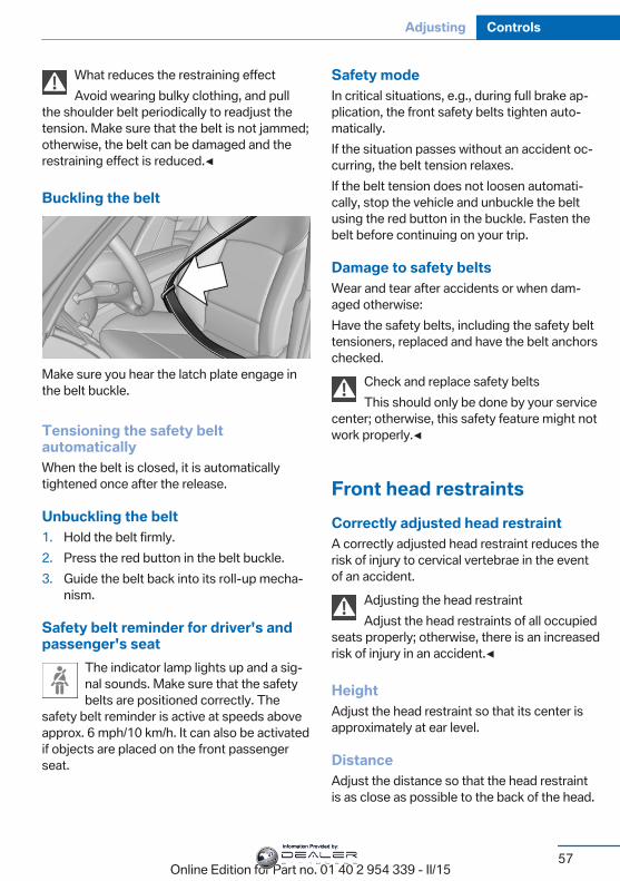
What reduces the restraining effectAvoid wearing bulky clothing, and pull
the shoulder belt periodically to readjust thetension. Make sure that the belt is not jammed;otherwise, the belt can be damaged and therestraining effect is reduced.◀
Buckling the belt
Make sure you hear the latch plate engage inthe belt buckle.
Tensioning the safety beltautomaticallyWhen the belt is closed, it is automaticallytightened once after the release.
Unbuckling the belt1. Hold the belt firmly.2. Press the red button in the belt buckle.3. Guide the belt back into its roll-up mecha‐
nism.
Safety belt reminder for driver's andpassenger's seat
The indicator lamp lights up and a sig‐nal sounds. Make sure that the safetybelts are positioned correctly. The
safety belt reminder is active at speeds aboveapprox. 6 mph/10 km/h. It can also be activatedif objects are placed on the front passengerseat.
Safety modeIn critical situations, e.g., during full brake ap‐plication, the front safety belts tighten auto‐matically.If the situation passes without an accident oc‐curring, the belt tension relaxes.If the belt tension does not loosen automati‐cally, stop the vehicle and unbuckle the beltusing the red button in the buckle. Fasten thebelt before continuing on your trip.
Damage to safety beltsWear and tear after accidents or when dam‐aged otherwise:Have the safety belts, including the safety belttensioners, replaced and have the belt anchorschecked.
Check and replace safety beltsThis should only be done by your service
center; otherwise, this safety feature might notwork properly.◀
Front head restraintsCorrectly adjusted head restraintA correctly adjusted head restraint reduces therisk of injury to cervical vertebrae in the eventof an accident.
Adjusting the head restraintAdjust the head restraints of all occupied
seats properly; otherwise, there is an increasedrisk of injury in an accident.◀
HeightAdjust the head restraint so that its center isapproximately at ear level.
DistanceAdjust the distance so that the head restraintis as close as possible to the back of the head.
Seite 57
Adjusting Controls
57Online Edition for Part no. 01 40 2 954 339 - II/15
Information Provided by:
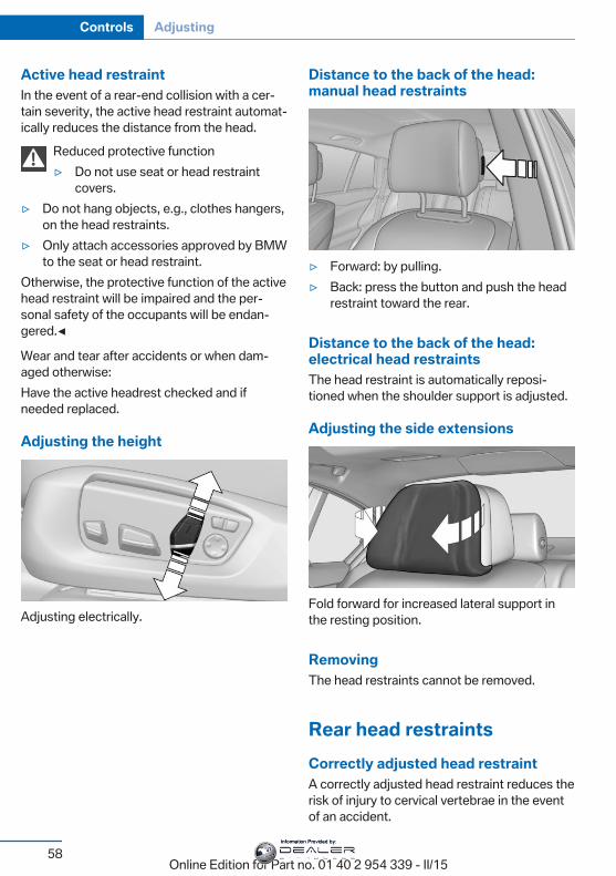
Active head restraintIn the event of a rear-end collision with a cer‐tain severity, the active head restraint automat‐ically reduces the distance from the head.
Reduced protective function▷ Do not use seat or head restraint
covers.▷ Do not hang objects, e.g., clothes hangers,
on the head restraints.▷ Only attach accessories approved by BMW
to the seat or head restraint.Otherwise, the protective function of the activehead restraint will be impaired and the per‐sonal safety of the occupants will be endan‐gered.◀
Wear and tear after accidents or when dam‐aged otherwise:Have the active headrest checked and ifneeded replaced.
Adjusting the height
Adjusting electrically.
Distance to the back of the head:manual head restraints
▷ Forward: by pulling.▷ Back: press the button and push the head
restraint toward the rear.
Distance to the back of the head:electrical head restraintsThe head restraint is automatically reposi‐tioned when the shoulder support is adjusted.
Adjusting the side extensions
Fold forward for increased lateral support inthe resting position.
RemovingThe head restraints cannot be removed.
Rear head restraintsCorrectly adjusted head restraintA correctly adjusted head restraint reduces therisk of injury to cervical vertebrae in the eventof an accident.
Seite 58
Controls Adjusting
58Online Edition for Part no. 01 40 2 954 339 - II/15
Information Provided by:
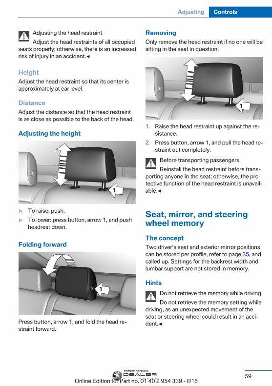
Adjusting the head restraintAdjust the head restraints of all occupied
seats properly; otherwise, there is an increasedrisk of injury in an accident.◀
HeightAdjust the head restraint so that its center isapproximately at ear level.
DistanceAdjust the distance so that the head restraintis as close as possible to the back of the head.
Adjusting the height
▷ To raise: push.▷ To lower: press button, arrow 1, and push
headrest down.
Folding forward
Press button, arrow 1, and fold the head re‐straint forward.
RemovingOnly remove the head restraint if no one will besitting in the seat in question.
1. Raise the head restraint up against the re‐sistance.
2. Press button, arrow 1, and pull the head re‐straint out completely.
Before transporting passengersReinstall the head restraint before trans‐
porting anyone in the seat; otherwise, the pro‐tective function of the head restraint is unavail‐able.◀
Seat, mirror, and steeringwheel memoryThe conceptTwo driver's seat and exterior mirror positionscan be stored per profile, refer to page 35, andcalled up. Settings for the backrest width andlumbar support are not stored in memory.
HintsDo not retrieve the memory while drivingDo not retrieve the memory setting while
driving, as an unexpected movement of theseat or steering wheel could result in an acci‐dent.◀
Seite 59
Adjusting Controls
59Online Edition for Part no. 01 40 2 954 339 - II/15
Information Provided by:
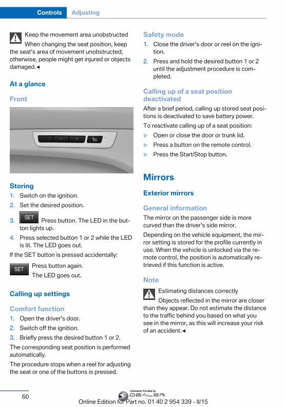
Keep the movement area unobstructedWhen changing the seat position, keep
the seat's area of movement unobstructed;otherwise, people might get injured or objectsdamaged.◀
At a glance
Front
Storing1. Switch on the ignition.2. Set the desired position.
3. Press button. The LED in the but‐ton lights up.
4. Press selected button 1 or 2 while the LEDis lit. The LED goes out.
If the SET button is pressed accidentally:Press button again.The LED goes out.
Calling up settings
Comfort function1. Open the driver's door.2. Switch off the ignition.3. Briefly press the desired button 1 or 2.The corresponding seat position is performedautomatically.The procedure stops when a reel for adjustingthe seat or one of the buttons is pressed.
Safety mode1. Close the driver's door or reel on the igni‐
tion.2. Press and hold the desired button 1 or 2
until the adjustment procedure is com‐pleted.
Calling up of a seat positiondeactivatedAfter a brief period, calling up stored seat posi‐tions is deactivated to save battery power.To reactivate calling up of a seat position:▷ Open or close the door or trunk lid.▷ Press a button on the remote control.▷ Press the Start/Stop button.
MirrorsExterior mirrors
General informationThe mirror on the passenger side is morecurved than the driver's side mirror.Depending on the vehicle equipment, the mir‐ror setting is stored for the profile currently inuse. When the vehicle is unlocked via the re‐mote control, the position is automatically re‐trieved if this function is active.
NoteEstimating distances correctlyObjects reflected in the mirror are closer
than they appear. Do not estimate the distanceto the traffic behind you based on what yousee in the mirror, as this will increase your riskof an accident.◀
Seite 60
Controls Adjusting
60Online Edition for Part no. 01 40 2 954 339 - II/15
Information Provided by:
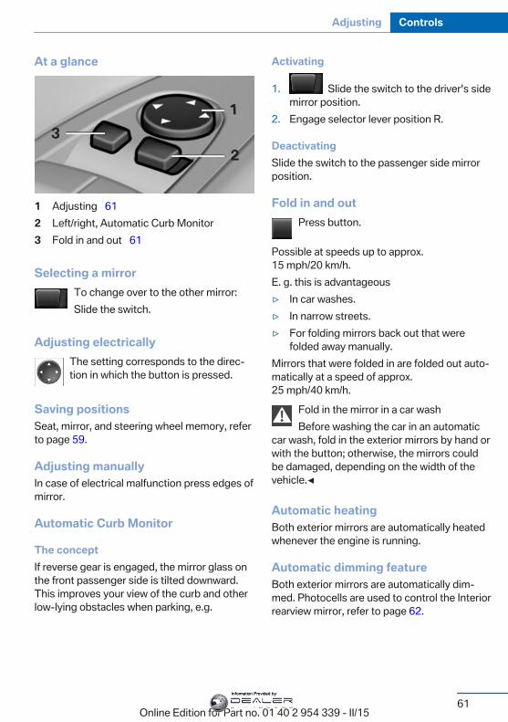
At a glance
1 Adjusting 612 Left/right, Automatic Curb Monitor3 Fold in and out 61
Selecting a mirrorTo change over to the other mirror:Slide the switch.
Adjusting electricallyThe setting corresponds to the direc‐tion in which the button is pressed.
Saving positionsSeat, mirror, and steering wheel memory, referto page 59.
Adjusting manuallyIn case of electrical malfunction press edges ofmirror.
Automatic Curb Monitor
The conceptIf reverse gear is engaged, the mirror glass onthe front passenger side is tilted downward.This improves your view of the curb and otherlow-lying obstacles when parking, e.g.
Activating
1. Slide the switch to the driver's sidemirror position.
2. Engage selector lever position R.
DeactivatingSlide the switch to the passenger side mirrorposition.
Fold in and outPress button.
Possible at speeds up to approx.15 mph/20 km/h.E. g. this is advantageous▷ In car washes.▷ In narrow streets.▷ For folding mirrors back out that were
folded away manually.Mirrors that were folded in are folded out auto‐matically at a speed of approx.25 mph/40 km/h.
Fold in the mirror in a car washBefore washing the car in an automatic
car wash, fold in the exterior mirrors by hand orwith the button; otherwise, the mirrors couldbe damaged, depending on the width of thevehicle.◀
Automatic heatingBoth exterior mirrors are automatically heatedwhenever the engine is running.
Automatic dimming featureBoth exterior mirrors are automatically dim‐med. Photocells are used to control the Interiorrearview mirror, refer to page 62.
Seite 61
Adjusting Controls
61Online Edition for Part no. 01 40 2 954 339 - II/15
Information Provided by:
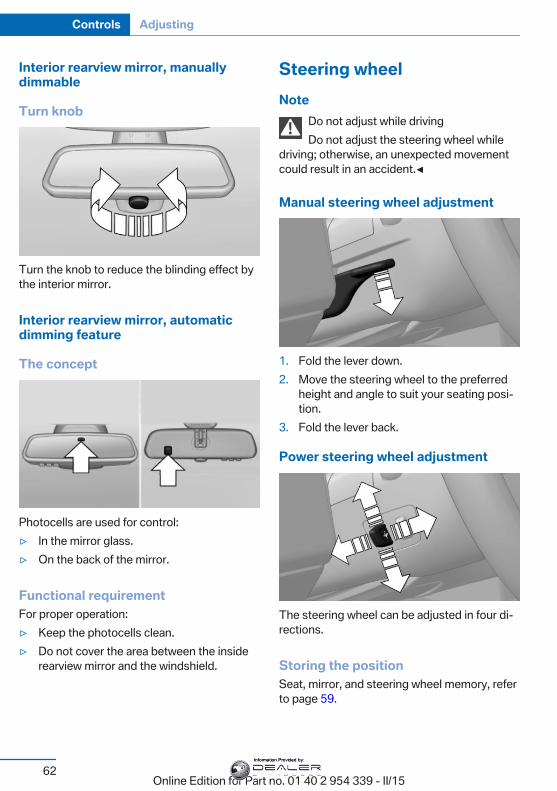
Interior rearview mirror, manuallydimmable
Turn knob
Turn the knob to reduce the blinding effect bythe interior mirror.
Interior rearview mirror, automaticdimming feature
The concept
Photocells are used for control:▷ In the mirror glass.▷ On the back of the mirror.
Functional requirementFor proper operation:▷ Keep the photocells clean.▷ Do not cover the area between the inside
rearview mirror and the windshield.
Steering wheelNote
Do not adjust while drivingDo not adjust the steering wheel while
driving; otherwise, an unexpected movementcould result in an accident.◀
Manual steering wheel adjustment
1. Fold the lever down.2. Move the steering wheel to the preferred
height and angle to suit your seating posi‐tion.
3. Fold the lever back.
Power steering wheel adjustment
The steering wheel can be adjusted in four di‐rections.
Storing the positionSeat, mirror, and steering wheel memory, referto page 59.
Seite 62
Controls Adjusting
62Online Edition for Part no. 01 40 2 954 339 - II/15
Information Provided by:
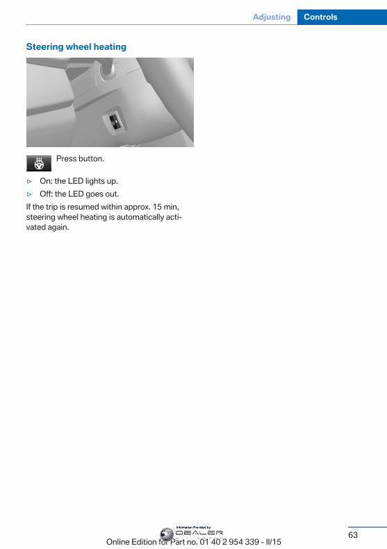
Steering wheel heating
Press button.
▷ On: the LED lights up.▷ Off: the LED goes out.If the trip is resumed within approx. 15 min,steering wheel heating is automatically acti‐vated again.
Seite 63
Adjusting Controls
63Online Edition for Part no. 01 40 2 954 339 - II/15
Information Provided by:
Transporting children safelyVehicle features and optionsThis chapter describes all standard, country-specific and optional features offered with theseries. It also describes features that are notnecessarily available in your car, e. g., due to
the selected options or country versions. Thisalso applies to safety-related functions andsystems. The respectively applicable countryprovisions must be observed when using therespective features and systems.
The right place for childrenNote
Children in the vehicleDo not leave children unattended in the
vehicle; otherwise, they could endanger them‐selves and other persons, e.g., by opening thedoors.◀
Children should always be in the rearAccident research shows that the safest placefor children is in the back seat.
Transporting children in the rearOnly transport children younger than
13 years of age or shorter than 5 ft/150 cm inthe rear in child restraint systems provided inaccordance with the age, weight and size ofthe child; otherwise, there is an increased riskof injury in an accident.Children 13 years of age or older must wear asafety belt as soon as a suitable child restraintsystem can no longer be used due to their age,weight and size.◀
Children on the front passenger seatShould it ever be necessary to use a child re‐straint system in the front passenger seat,make sure that the front, knee and side airbagson the front passenger side are deactivated.Automatic deactivation of front-seat passen‐ger airbags, refer to page 107.
NoteDeactivating the front-seat passengerairbags
If a child restraint system is used in the frontpassenger seat, deactivate the front-seat pas‐senger airbags; otherwise, there is an in‐creased risk of injury to the child when the air‐bags are activated, even with a child restraintsystem.◀
Installing child restraintsystemsHints
Manufacturer's information for child re‐straint systems
To select, mount and use child restraint sys‐tems, observe the information provided by thesystem manufacturer; otherwise, the protec‐tive effect can be lost.◀
Ensuring the stability of the child seatWhen installing child restraint systems,
make sure that the child seat is securely fas‐tened to the backrest of the seat. Angle andheadrest of the backrest might need to be ad‐justed or possibly be removed. Make sure thatall backrests are securely locked. Otherwisethe stability of the child seat can be affected,and there is an increased risk of injury because
Seite 64
Controls Transporting children safely
64Online Edition for Part no. 01 40 2 954 339 - II/15
Information Provided by:
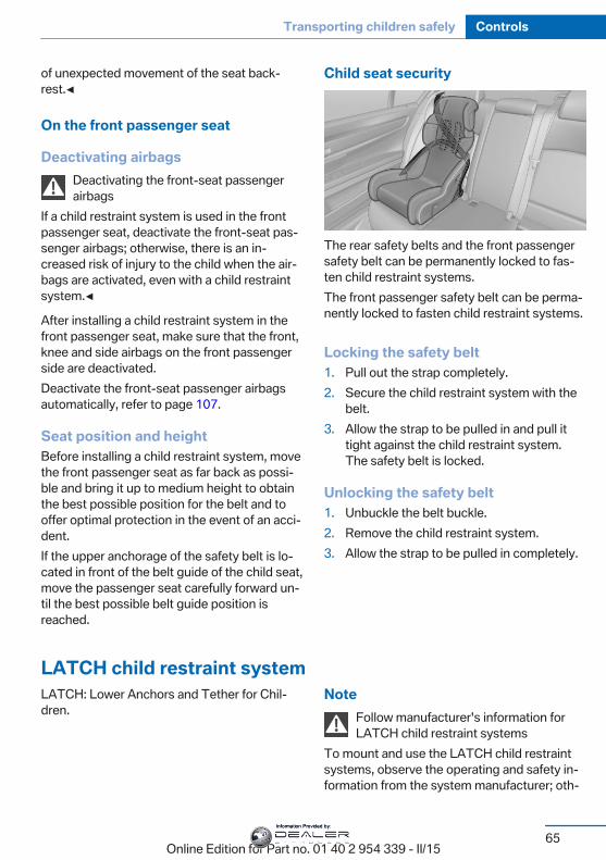
of unexpected movement of the seat back‐rest.◀
On the front passenger seat
Deactivating airbagsDeactivating the front-seat passengerairbags
If a child restraint system is used in the frontpassenger seat, deactivate the front-seat pas‐senger airbags; otherwise, there is an in‐creased risk of injury to the child when the air‐bags are activated, even with a child restraintsystem.◀
After installing a child restraint system in thefront passenger seat, make sure that the front,knee and side airbags on the front passengerside are deactivated.Deactivate the front-seat passenger airbagsautomatically, refer to page 107.
Seat position and heightBefore installing a child restraint system, movethe front passenger seat as far back as possi‐ble and bring it up to medium height to obtainthe best possible position for the belt and tooffer optimal protection in the event of an acci‐dent.If the upper anchorage of the safety belt is lo‐cated in front of the belt guide of the child seat,move the passenger seat carefully forward un‐til the best possible belt guide position isreached.
Child seat security
The rear safety belts and the front passengersafety belt can be permanently locked to fas‐ten child restraint systems.The front passenger safety belt can be perma‐nently locked to fasten child restraint systems.
Locking the safety belt1. Pull out the strap completely.2. Secure the child restraint system with the
belt.3. Allow the strap to be pulled in and pull it
tight against the child restraint system.The safety belt is locked.
Unlocking the safety belt1. Unbuckle the belt buckle.2. Remove the child restraint system.3. Allow the strap to be pulled in completely.
LATCH child restraint systemLATCH: Lower Anchors and Tether for Chil‐dren.
NoteFollow manufacturer's information forLATCH child restraint systems
To mount and use the LATCH child restraintsystems, observe the operating and safety in‐formation from the system manufacturer; oth‐
Seite 65
Transporting children safely Controls
65Online Edition for Part no. 01 40 2 954 339 - II/15
Information Provided by:
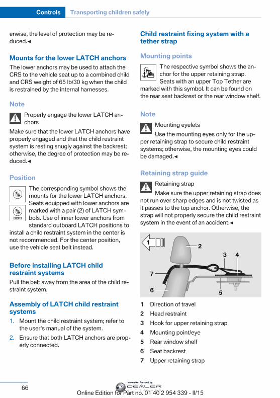
erwise, the level of protection may be re‐duced.◀
Mounts for the lower LATCH anchorsThe lower anchors may be used to attach theCRS to the vehicle seat up to a combined childand CRS weight of 65 lb/30 kg when the childis restrained by the internal harnesses.
NoteProperly engage the lower LATCH an‐chors
Make sure that the lower LATCH anchors haveproperly engaged and that the child restraintsystem is resting snugly against the backrest;otherwise, the degree of protection may be re‐duced.◀
PositionThe corresponding symbol shows themounts for the lower LATCH anchors.Seats equipped with lower anchors aremarked with a pair (2) of LATCH sym‐bols. Use of inner lower anchors fromstandard outboard LATCH positions to
install a child restraint system in the center isnot recommended. For the center position,use the vehicle seat belt instead.
Before installing LATCH childrestraint systemsPull the belt away from the area of the child re‐straint system.
Assembly of LATCH child restraintsystems1. Mount the child restraint system; refer to
the user's manual of the system.2. Ensure that both LATCH anchors are prop‐
erly connected.
Child restraint fixing system with atether strap
Mounting pointsThe respective symbol shows the an‐chor for the upper retaining strap.Seats with an upper Top Tether are
marked with this symbol. It can be found onthe rear seat backrest or the rear window shelf.
NoteMounting eyeletsUse the mounting eyes only for the up‐
per retaining strap to secure child restraintsystems; otherwise, the mounting eyes couldbe damaged.◀
Retaining strap guideRetaining strapMake sure the upper retaining strap does
not run over sharp edges and is not twisted asit passes to the top anchor. Otherwise, thestrap will not properly secure the child restraintsystem in the event of an accident.◀
1 Direction of travel2 Head restraint3 Hook for upper retaining strap4 Mounting point/eye5 Rear window shelf6 Seat backrest7 Upper retaining strap
Seite 66
Controls Transporting children safely
66Online Edition for Part no. 01 40 2 954 339 - II/15
Information Provided by:
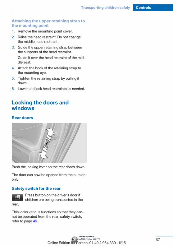
Attaching the upper retaining strap tothe mounting point1. Remove the mounting point cover.2. Raise the head restraint. Do not change
the middle head restraint.3. Guide the upper retaining strap between
the supports of the head restraint.Guide it over the head restraint of the mid‐dle seat.
4. Attach the hook of the retaining strap tothe mounting eye.
5. Tighten the retaining strap by pulling itdown.
6. Lower and lock head restraints as needed.
Locking the doors andwindowsRear doors
Push the locking lever on the rear doors down.
The door can now be opened from the outsideonly.
Safety switch for the rearPress button on the driver's door ifchildren are being transported in the
rear.
This locks various functions so that they can‐not be operated from the rear: safety switch,refer to page 49.
Seite 67
Transporting children safely Controls
67Online Edition for Part no. 01 40 2 954 339 - II/15
Information Provided by:

DrivingVehicle features and optionsThis chapter describes all standard, country-specific and optional features offered with theseries. It also describes features that are notnecessarily available in your car, e. g., due tothe selected options or country versions. Thisalso applies to safety-related functions andsystems. The respectively applicable countryprovisions must be observed when using therespective features and systems.
Start/Stop buttonThe concept
Pressing the Start/Stop buttonswitches the ignition on or offand starts the engine.M Double-clutch transmission:The engine starts if the brakes
are stepped on while pressing the Start/Stopbutton.Manual transmission: The engine starts withthe clutch pedal pressed when the Start/Stopbutton is pressed.
Ignition onM double-clutch transmission: Press the Start/Stop button without stepping on the brake.Manual transmission: Press the Start/Stop but‐ton without stepping on the clutch pedal.All vehicle systems are ready for operation.Most of the indicator and warning lights in theinstrument cluster light up for a varied lengthof time.To save battery power when the engine is off,switch off the ignition and any unnecessaryelectronic systems/power consumers.
Ignition offM double-clutch transmission: Press the Start/Stop button again without stepping on thebrake.Manual transmission: Press the Start/Stop but‐ton again without stepping on the clutch pedal.All indicator lights in the instrument cluster goout.To save battery power when the engine is off,switch off the ignition and any unnecessaryelectronic systems/power consumers.
P when the ignition is switched offP is engaged automatically when the ig‐
nition is switched off. When in an automatic carwash, e.g., ensure that the ignition is notswitched off accidentally.◀
The ignition automatically cuts off while thevehicle is stationary and the engine is stopped:▷ When locking the vehicle, and when the
low beams are activated.▷ Shortly before the battery is discharged
completely, so that the engine can still bestarted. This function is only availablewhen the low beams are turned off.
▷ When opening or closing the driver door, ifthe driver's safety belt is unbuckled andthe low beams are turned off.
▷ While the driver's safety belt is unbuckledwith driver's door open and low beams off.
The low beams switch to parking lights afterapprox. 15 minutes of no use.
Radio ready stateActivate radio-ready state:▷ When the engine is running: press the
Start/Stop button.Some electronic systems/power consumersremain ready for operation.
Seite 68
Controls Driving
68Online Edition for Part no. 01 40 2 954 339 - II/15
Information Provided by:
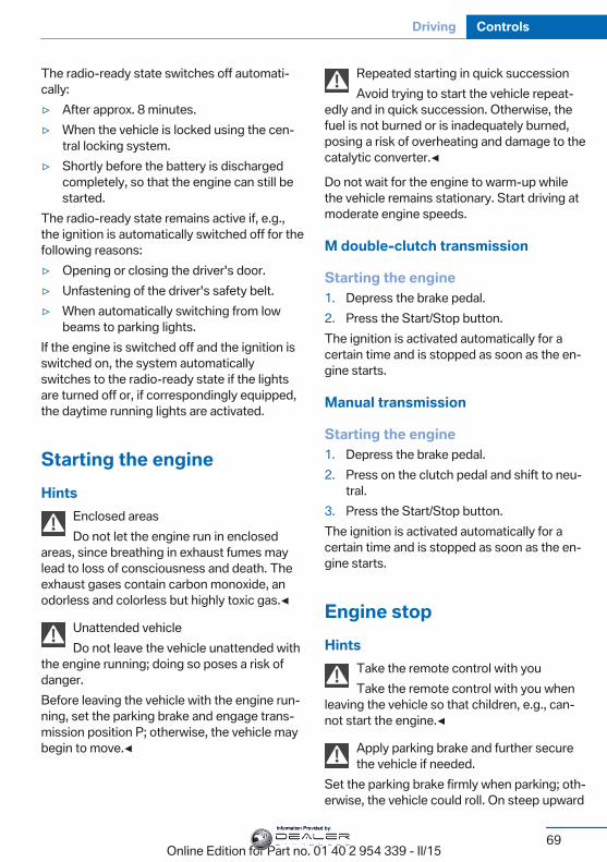
The radio-ready state switches off automati‐cally:▷ After approx. 8 minutes.▷ When the vehicle is locked using the cen‐
tral locking system.▷ Shortly before the battery is discharged
completely, so that the engine can still bestarted.
The radio-ready state remains active if, e.g.,the ignition is automatically switched off for thefollowing reasons:▷ Opening or closing the driver's door.▷ Unfastening of the driver's safety belt.▷ When automatically switching from low
beams to parking lights.If the engine is switched off and the ignition isswitched on, the system automaticallyswitches to the radio-ready state if the lightsare turned off or, if correspondingly equipped,the daytime running lights are activated.
Starting the engineHints
Enclosed areasDo not let the engine run in enclosed
areas, since breathing in exhaust fumes maylead to loss of consciousness and death. Theexhaust gases contain carbon monoxide, anodorless and colorless but highly toxic gas.◀
Unattended vehicleDo not leave the vehicle unattended with
the engine running; doing so poses a risk ofdanger.Before leaving the vehicle with the engine run‐ning, set the parking brake and engage trans‐mission position P; otherwise, the vehicle maybegin to move.◀
Repeated starting in quick successionAvoid trying to start the vehicle repeat‐
edly and in quick succession. Otherwise, thefuel is not burned or is inadequately burned,posing a risk of overheating and damage to thecatalytic converter.◀
Do not wait for the engine to warm-up whilethe vehicle remains stationary. Start driving atmoderate engine speeds.
M double-clutch transmission
Starting the engine1. Depress the brake pedal.2. Press the Start/Stop button.The ignition is activated automatically for acertain time and is stopped as soon as the en‐gine starts.
Manual transmission
Starting the engine1. Depress the brake pedal.2. Press on the clutch pedal and shift to neu‐
tral.3. Press the Start/Stop button.The ignition is activated automatically for acertain time and is stopped as soon as the en‐gine starts.
Engine stopHints
Take the remote control with youTake the remote control with you when
leaving the vehicle so that children, e.g., can‐not start the engine.◀
Apply parking brake and further securethe vehicle if needed.
Set the parking brake firmly when parking; oth‐erwise, the vehicle could roll. On steep upward
Seite 69
Driving Controls
69Online Edition for Part no. 01 40 2 954 339 - II/15
Information Provided by:
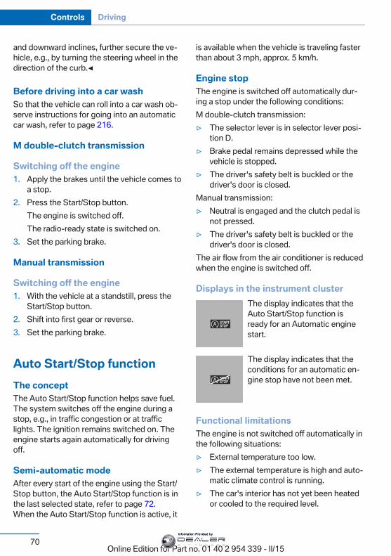
and downward inclines, further secure the ve‐hicle, e.g., by turning the steering wheel in thedirection of the curb.◀
Before driving into a car washSo that the vehicle can roll into a car wash ob‐serve instructions for going into an automaticcar wash, refer to page 216.
M double-clutch transmission
Switching off the engine1. Apply the brakes until the vehicle comes to
a stop.2. Press the Start/Stop button.
The engine is switched off.The radio-ready state is switched on.
3. Set the parking brake.
Manual transmission
Switching off the engine1. With the vehicle at a standstill, press the
Start/Stop button.2. Shift into first gear or reverse.3. Set the parking brake.
Auto Start/Stop functionThe conceptThe Auto Start/Stop function helps save fuel.The system switches off the engine during astop, e.g., in traffic congestion or at trafficlights. The ignition remains switched on. Theengine starts again automatically for drivingoff.
Semi-automatic modeAfter every start of the engine using the Start/Stop button, the Auto Start/Stop function is inthe last selected state, refer to page 72.When the Auto Start/Stop function is active, it
is available when the vehicle is traveling fasterthan about 3 mph, approx. 5 km/h.
Engine stopThe engine is switched off automatically dur‐ing a stop under the following conditions:M double-clutch transmission:▷ The selector lever is in selector lever posi‐
tion D.▷ Brake pedal remains depressed while the
vehicle is stopped.▷ The driver's safety belt is buckled or the
driver's door is closed.Manual transmission:▷ Neutral is engaged and the clutch pedal is
not pressed.▷ The driver's safety belt is buckled or the
driver's door is closed.The air flow from the air conditioner is reducedwhen the engine is switched off.
Displays in the instrument clusterThe display indicates that theAuto Start/Stop function isready for an Automatic enginestart.
The display indicates that theconditions for an automatic en‐gine stop have not been met.
Functional limitationsThe engine is not switched off automatically inthe following situations:▷ External temperature too low.▷ The external temperature is high and auto‐
matic climate control is running.▷ The car's interior has not yet been heated
or cooled to the required level.
Seite 70
Controls Driving
70Online Edition for Part no. 01 40 2 954 339 - II/15
Information Provided by:
▷ The engine is not yet at operating temper‐ature.
▷ The wheels are at a sharp angle or thesteering wheel is being turned.
▷ After driving in reverse.▷ Fogging of the windows when the auto‐
matic climate control is switched on.▷ Vehicle battery is heavily discharged.▷ At higher elevations.▷ The engine compartment lid is unlocked.▷ Stop-and-go traffic.▷ Use of fuel with high ethanol content.
Starting the engineThe engine starts automatically under the fol‐lowing conditions:▷ M double-clutch transmission:
By releasing the brake pedal.▷ Manual transmission:
The clutch pedal is pressed.After the engine starts, accelerate as usual.
Safety modeAfter the engine switches off automatically, itwill not start again automatically if any one ofthe following conditions are met.▷ The driver's safety belt is unbuckled and
the driver's door is open.▷ The hood was unlocked.Some indicator lights light up for a variedlength of time.The engine can only be started via the Start/Stop button.
Functional limitationsEven if driving off was not intended, the deacti‐vated engine starts up automatically in the fol‐lowing situations:▷ Excessive warming of the car's interior
when the cooling function is switched on.
▷ The steering wheel is turned.▷ Double-clutch transmission: Change from
selector lever position D to N, R or D/S.▷ M double-clutch transmission: Accelerat‐
ing while simultaneously applying thebrake.
▷ The vehicle begins rolling.▷ Fogging of the windows when the auto‐
matic climate control is switched on.▷ Vehicle battery is heavily discharged.▷ Excessive cooling of the car's interior when
the heating is switched on.▷ Low brake vacuum pressure; this can oc‐
cur, e.g., if the brake pedal is depressed anumber of times in succession.
Preventing an automatic engine stopwith aM double-clutch transmission
The conceptTo make it possible to drive off very quickly,such as at an intersection, the automatic en‐gine stop can be actively prevented.
Preventing an engine stop using thebrake pedalThe engine stop can be actively preventedwithin one second after the vehicle comes to astandstill.▷ Immediately after the vehicle comes to a
standstill, briefly press the brake pedalforcefully.
▷ Then press the brake pedal with normalbraking force.
Seite 71
Driving Controls
71Online Edition for Part no. 01 40 2 954 339 - II/15
Information Provided by:
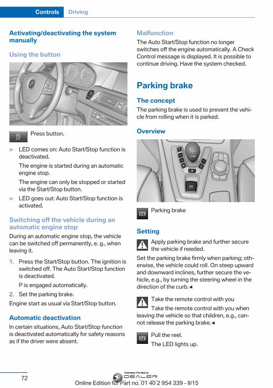
Activating/deactivating the systemmanually
Using the button
Press button.
▷ LED comes on: Auto Start/Stop function isdeactivated.The engine is started during an automaticengine stop.The engine can only be stopped or startedvia the Start/Stop button.
▷ LED goes out: Auto Start/Stop function isactivated.
Switching off the vehicle during anautomatic engine stopDuring an automatic engine stop, the vehiclecan be switched off permanently, e. g., whenleaving it.
1. Press the Start/Stop button. The ignition isswitched off. The Auto Start/Stop functionis deactivated.P is engaged automatically.
2. Set the parking brake.Engine start as usual via Start/Stop button.
Automatic deactivationIn certain situations, Auto Start/Stop functionis deactivated automatically for safety reasonsas if the driver were absent.
MalfunctionThe Auto Start/Stop function no longerswitches off the engine automatically. A CheckControl message is displayed. It is possible tocontinue driving. Have the system checked.
Parking brakeThe conceptThe parking brake is used to prevent the vehi‐cle from rolling when it is parked.
Overview
Parking brake
SettingApply parking brake and further securethe vehicle if needed.
Set the parking brake firmly when parking; oth‐erwise, the vehicle could roll. On steep upwardand downward inclines, further secure the ve‐hicle, e.g., by turning the steering wheel in thedirection of the curb.◀
Take the remote control with youTake the remote control with you when
leaving the vehicle so that children, e.g., can‐not release the parking brake.◀
Pull the reel.The LED lights up.
Seite 72
Controls Driving
72Online Edition for Part no. 01 40 2 954 339 - II/15
Information Provided by:
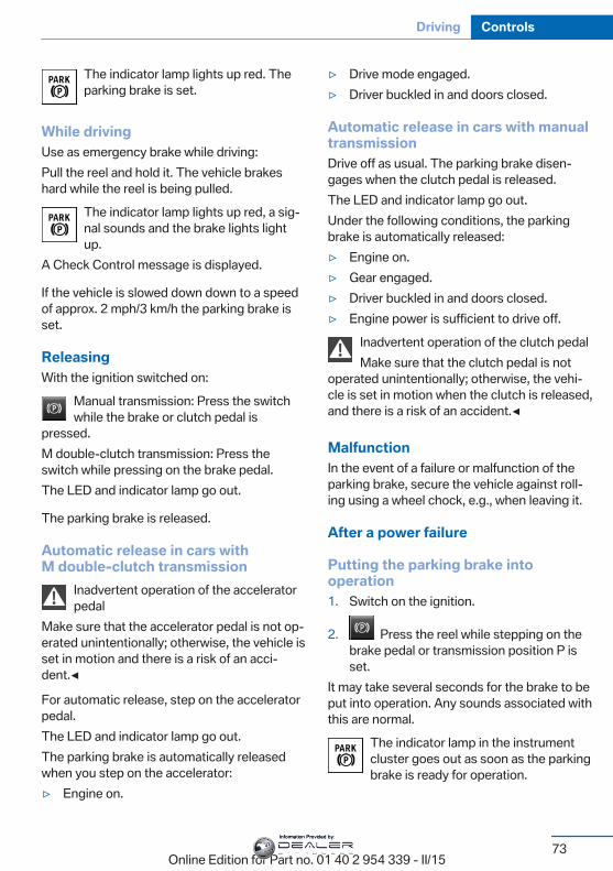
The indicator lamp lights up red. Theparking brake is set.
While drivingUse as emergency brake while driving:Pull the reel and hold it. The vehicle brakeshard while the reel is being pulled.
The indicator lamp lights up red, a sig‐nal sounds and the brake lights lightup.
A Check Control message is displayed.
If the vehicle is slowed down down to a speedof approx. 2 mph/3 km/h the parking brake isset.
ReleasingWith the ignition switched on:
Manual transmission: Press the switchwhile the brake or clutch pedal is
pressed.M double-clutch transmission: Press theswitch while pressing on the brake pedal.The LED and indicator lamp go out.
The parking brake is released.
Automatic release in cars withM double-clutch transmission
Inadvertent operation of the acceleratorpedal
Make sure that the accelerator pedal is not op‐erated unintentionally; otherwise, the vehicle isset in motion and there is a risk of an acci‐dent.◀
For automatic release, step on the acceleratorpedal.The LED and indicator lamp go out.The parking brake is automatically releasedwhen you step on the accelerator:▷ Engine on.
▷ Drive mode engaged.▷ Driver buckled in and doors closed.
Automatic release in cars with manualtransmissionDrive off as usual. The parking brake disen‐gages when the clutch pedal is released.The LED and indicator lamp go out.Under the following conditions, the parkingbrake is automatically released:▷ Engine on.▷ Gear engaged.▷ Driver buckled in and doors closed.▷ Engine power is sufficient to drive off.
Inadvertent operation of the clutch pedalMake sure that the clutch pedal is not
operated unintentionally; otherwise, the vehi‐cle is set in motion when the clutch is released,and there is a risk of an accident.◀
MalfunctionIn the event of a failure or malfunction of theparking brake, secure the vehicle against roll‐ing using a wheel chock, e.g., when leaving it.
After a power failure
Putting the parking brake intooperation1. Switch on the ignition.
2. Press the reel while stepping on thebrake pedal or transmission position P isset.
It may take several seconds for the brake to beput into operation. Any sounds associated withthis are normal.
The indicator lamp in the instrumentcluster goes out as soon as the parkingbrake is ready for operation.
Seite 73
Driving Controls
73Online Edition for Part no. 01 40 2 954 339 - II/15
Information Provided by:
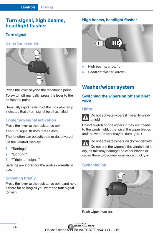
Turn signal, high beams,headlight flasherTurn signal
Using turn signals
Press the lever beyond the resistance point.To switch off manually, press the lever to theresistance point.
Unusually rapid flashing of the indicator lampindicates that a turn signal bulb has failed.
Triple turn signal activationPress the lever to the resistance point.The turn signal flashes three times.The function can be activated or deactivated.On the Control Display:
1. "Settings"2. "Lighting"3. "Triple turn signal"Settings are stored for the profile currently inuse.
Signaling brieflyPress the lever to the resistance point and holdit there for as long as you want the turn signalto flash.
High beams, headlight flasher
▷ High beams, arrow 1.▷ Headlight flasher, arrow 2.
Washer/wiper systemSwitching the wipers on/off and briefwipe
HintsDo not activate wipers if frozen to wind‐shield
Do not switch on the wipers if they are frozento the windshield; otherwise, the wiper bladesand the wiper motor may be damaged.◀
Do not activate wipers on dry windshieldDo not use the wipers if the windshield is
dry, as this may damage the wiper blades orcause them to become worn more quickly.◀
Switching on
Push wiper lever up.
Seite 74
Controls Driving
74Online Edition for Part no. 01 40 2 954 339 - II/15
Information Provided by:
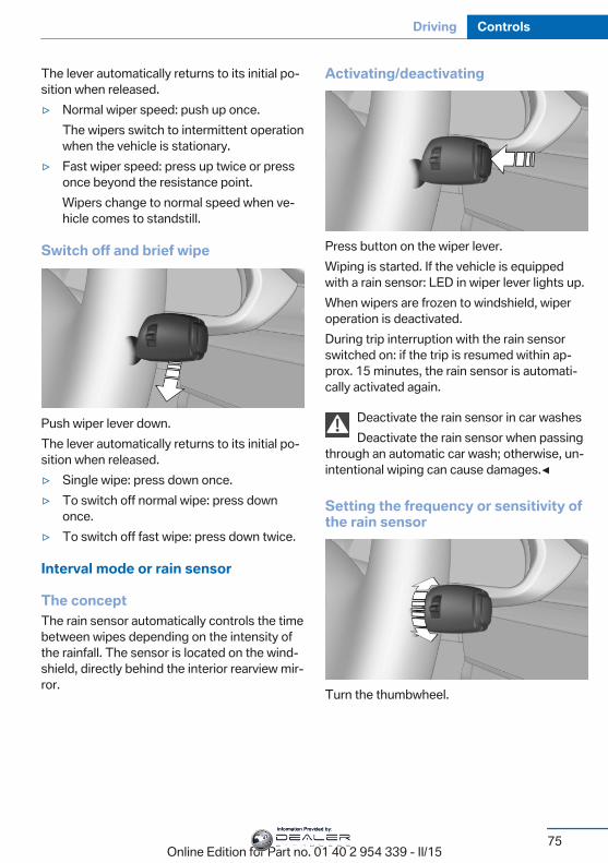
The lever automatically returns to its initial po‐sition when released.▷ Normal wiper speed: push up once.
The wipers switch to intermittent operationwhen the vehicle is stationary.
▷ Fast wiper speed: press up twice or pressonce beyond the resistance point.Wipers change to normal speed when ve‐hicle comes to standstill.
Switch off and brief wipe
Push wiper lever down.The lever automatically returns to its initial po‐sition when released.▷ Single wipe: press down once.▷ To switch off normal wipe: press down
once.▷ To switch off fast wipe: press down twice.
Interval mode or rain sensor
The conceptThe rain sensor automatically controls the timebetween wipes depending on the intensity ofthe rainfall. The sensor is located on the wind‐shield, directly behind the interior rearview mir‐ror.
Activating/deactivating
Press button on the wiper lever.Wiping is started. If the vehicle is equippedwith a rain sensor: LED in wiper lever lights up.When wipers are frozen to windshield, wiperoperation is deactivated.During trip interruption with the rain sensorswitched on: if the trip is resumed within ap‐prox. 15 minutes, the rain sensor is automati‐cally activated again.
Deactivate the rain sensor in car washesDeactivate the rain sensor when passing
through an automatic car wash; otherwise, un‐intentional wiping can cause damages.◀
Setting the frequency or sensitivity ofthe rain sensor
Turn the thumbwheel.
Seite 75
Driving Controls
75Online Edition for Part no. 01 40 2 954 339 - II/15
Information Provided by:
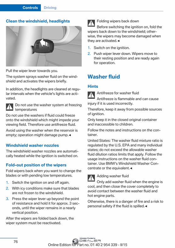
Clean the windshield, headlights
Pull the wiper lever towards you.The system sprays washer fluid on the wind‐shield and activates the wipers briefly.
In addition, the headlights are cleaned at regu‐lar intervals when the vehicle's lights are acti‐vated.
Do not use the washer system at freezingtemperatures
Do not use the washers if fluid could freezeonto the windshield which might impede yourviewing field. Therefore use antifreeze fluid.Avoid using the washer when the reservoir isempty; operation might damage pump.◀
Windshield washer nozzlesThe windshield washer nozzles are automati‐cally heated while the ignition is switched on.
Fold-out position of the wipersFold wipers back when you want to change theblades or with pending low temperatures.
1. Switch the ignition on and off again.2. With icy conditions make sure that blades
are not frozen to the windshield.3. Press the wiper lever up beyond the point
of resistance and hold it for approx. 3 sec‐onds, until the wiper remains in a nearlyvertical position.
After the wipers are folded back down, thewiper system must be reactivated.
Folding wipers back downBefore switching the ignition on, fold the
wipers back down to the windshield; other‐wise, the wipers may become damaged whenthey are activated.◀
1. Switch on the ignition.2. Push wiper lever down. Wipers move to
their resting position and are ready againfor operation.
Washer fluidHints
Antifreeze for washer fluidAntifreeze is flammable and can cause
injury if it is used incorrectly.Therefore, keep it away from possible sourcesof ignition.Only keep it in the closed original containerand inaccessible to children.Follow the notes and instructions on the con‐tainer.United States: The washer fluid mixture ratio isregulated by the U.S. EPA and many individualstates; do not exceed the allowable washerfluid dilution ratios limits that apply. Follow theusage instructions on the washer fluid con‐tainer. Use BMW’s Windshield Washer Con‐centrate or the equivalent.◀
Adding washer fluidOnly add washer fluid when the engine is
cool, and then close the cover completely toavoid contact between the washer fluid andhot engine parts.Otherwise, there is a danger of fire and a risk topersonal safety if the fluid is spilled.◀
Seite 76
Controls Driving
76Online Edition for Part no. 01 40 2 954 339 - II/15
Information Provided by:
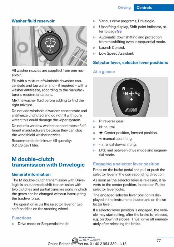
Washer fluid reservoir
All washer nozzles are supplied from one res‐ervoir.Fill with a mixture of windshield washer con‐centrate and tap water and – if required – with awasher antifreeze, according to the manufac‐turer's recommendations.Mix the washer fluid before adding to find theright mixture.Do not add windshield washer concentrate andantifreeze undiluted and do not fill with purewater; this could damage the wiper system.Do not mix window washer concentrates of dif‐ferent manufacturers because they can clogthe windshield washer nozzles.Recommended minimum fill quantity:0.2 US gal/1 liter.
M double-clutchtransmission with DrivelogicGeneral informationThe M double-clutch transmission with Drive‐logic is an automatic shift transmission withtwo clutches and partial transmissions in whichthe gears can be changed without interruptingthe tractive force.The operation is via the selector lever or twoshift paddles on the steering wheel.
Functions▷ Drive mode or Sequential mode.
▷ Various drive programs, Drivelogic.▷ Upshifting display, Shift point indicator, re‐
fer to page 99.▷ Automatic downshifting and protection
from misshifting even in sequential mode.▷ Launch Control.▷ Low Speed Assistant.
Selector lever, selector lever positions
At a glance
▷ R: reverse gear.▷ N: neutral.▷ Center position, forward position.▷ +: manual upshifting.▷ -: manual downshifting.▷ D/S: reel between drive mode and sequen‐
tial mode.
Engaging a selector lever positionPress on the brake pedal and pull or push theselector lever in the corresponding direction.As soon as the selector lever is released, it re‐verts to the center position. In position R, theselector lever locks.The engaged selector lever position is dis‐played in the instrument cluster and on the se‐lector lever.If a selector lever position is engaged, the vehi‐cle may start rolling, after the brake is released,e.g. on downhill slopes. Thus, drive off immedi‐ately after releasing the brake.
Seite 77
Driving Controls
77Online Edition for Part no. 01 40 2 954 339 - II/15
Information Provided by:
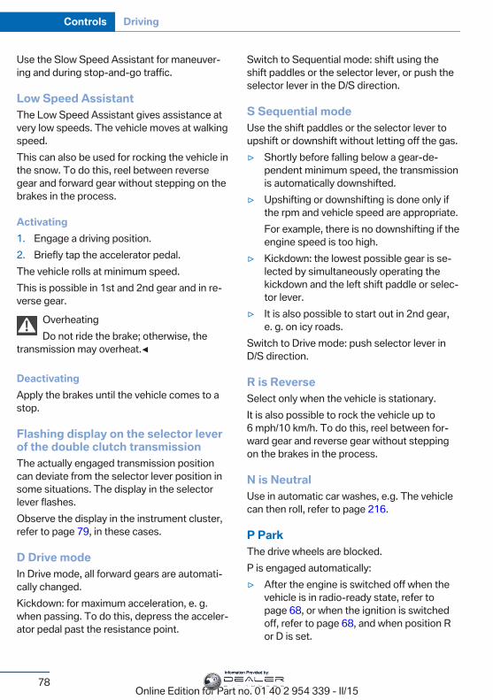
Use the Slow Speed Assistant for maneuver‐ing and during stop-and-go traffic.
Low Speed AssistantThe Low Speed Assistant gives assistance atvery low speeds. The vehicle moves at walkingspeed.This can also be used for rocking the vehicle inthe snow. To do this, reel between reversegear and forward gear without stepping on thebrakes in the process.
Activating1. Engage a driving position.2. Briefly tap the accelerator pedal.The vehicle rolls at minimum speed.This is possible in 1st and 2nd gear and in re‐verse gear.
OverheatingDo not ride the brake; otherwise, the
transmission may overheat.◀
DeactivatingApply the brakes until the vehicle comes to astop.
Flashing display on the selector leverof the double clutch transmissionThe actually engaged transmission positioncan deviate from the selector lever position insome situations. The display in the selectorlever flashes.Observe the display in the instrument cluster,refer to page 79, in these cases.
D Drive modeIn Drive mode, all forward gears are automati‐cally changed.Kickdown: for maximum acceleration, e. g.when passing. To do this, depress the acceler‐ator pedal past the resistance point.
Switch to Sequential mode: shift using theshift paddles or the selector lever, or push theselector lever in the D/S direction.
S Sequential modeUse the shift paddles or the selector lever toupshift or downshift without letting off the gas.▷ Shortly before falling below a gear-de‐
pendent minimum speed, the transmissionis automatically downshifted.
▷ Upshifting or downshifting is done only ifthe rpm and vehicle speed are appropriate.For example, there is no downshifting if theengine speed is too high.
▷ Kickdown: the lowest possible gear is se‐lected by simultaneously operating thekickdown and the left shift paddle or selec‐tor lever.
▷ It is also possible to start out in 2nd gear,e. g. on icy roads.
Switch to Drive mode: push selector lever inD/S direction.
R is ReverseSelect only when the vehicle is stationary.It is also possible to rock the vehicle up to6 mph/10 km/h. To do this, reel between for‐ward gear and reverse gear without steppingon the brakes in the process.
N is NeutralUse in automatic car washes, e.g. The vehiclecan then roll, refer to page 216.
P ParkThe drive wheels are blocked.P is engaged automatically:▷ After the engine is switched off when the
vehicle is in radio-ready state, refer topage 68, or when the ignition is switchedoff, refer to page 68, and when position Ror D is set.
Seite 78
Controls Driving
78Online Edition for Part no. 01 40 2 954 339 - II/15
Information Provided by:
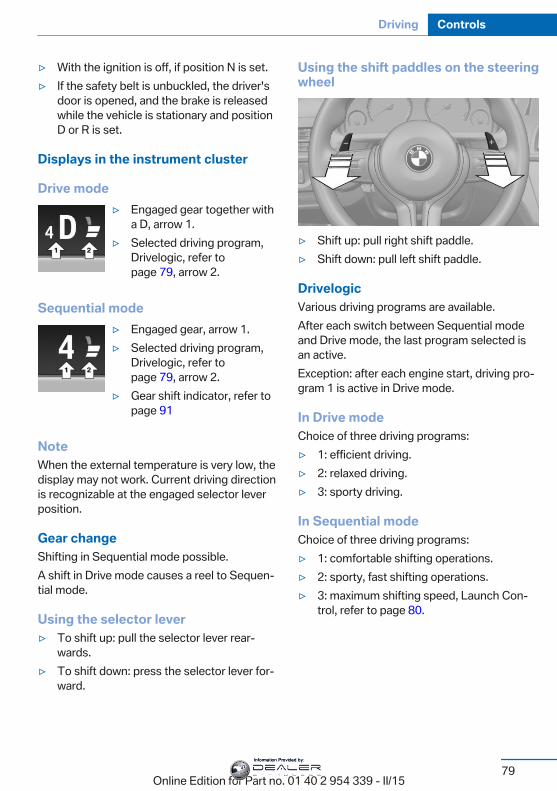
▷ With the ignition is off, if position N is set.▷ If the safety belt is unbuckled, the driver's
door is opened, and the brake is releasedwhile the vehicle is stationary and positionD or R is set.
Displays in the instrument cluster
Drive mode▷ Engaged gear together with
a D, arrow 1.▷ Selected driving program,
Drivelogic, refer topage 79, arrow 2.
Sequential mode▷ Engaged gear, arrow 1.▷ Selected driving program,
Drivelogic, refer topage 79, arrow 2.
▷ Gear shift indicator, refer topage 91
NoteWhen the external temperature is very low, thedisplay may not work. Current driving directionis recognizable at the engaged selector leverposition.
Gear changeShifting in Sequential mode possible.A shift in Drive mode causes a reel to Sequen‐tial mode.
Using the selector lever▷ To shift up: pull the selector lever rear‐
wards.▷ To shift down: press the selector lever for‐
ward.
Using the shift paddles on the steeringwheel
▷ Shift up: pull right shift paddle.▷ Shift down: pull left shift paddle.
DrivelogicVarious driving programs are available.After each switch between Sequential modeand Drive mode, the last program selected isan active.Exception: after each engine start, driving pro‐gram 1 is active in Drive mode.
In Drive modeChoice of three driving programs:▷ 1: efficient driving.▷ 2: relaxed driving.▷ 3: sporty driving.
In Sequential modeChoice of three driving programs:▷ 1: comfortable shifting operations.▷ 2: sporty, fast shifting operations.▷ 3: maximum shifting speed, Launch Con‐
trol, refer to page 80.
Seite 79
Driving Controls
79Online Edition for Part no. 01 40 2 954 339 - II/15
Information Provided by:
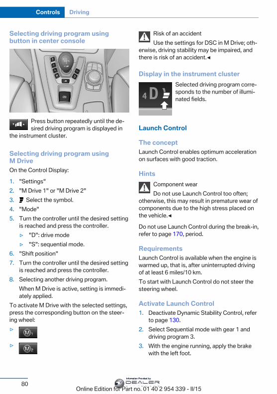
Selecting driving program usingbutton in center console
Press button repeatedly until the de‐sired driving program is displayed in
the instrument cluster.
Selecting driving program usingM DriveOn the Control Display:
1. "Settings"2. "M Drive 1" or "M Drive 2"3. Select the symbol.4. "Mode"5. Turn the controller until the desired setting
is reached and press the controller.▷ "D": drive mode▷ "S": sequential mode.
6. "Shift position"7. Turn the controller until the desired setting
is reached and press the controller.8. Selecting another driving program.
When M Drive is active, setting is immedi‐ately applied.
To activate M Drive with the selected settings,press the corresponding button on the steer‐ing wheel:▷
▷
Risk of an accidentUse the settings for DSC in M Drive; oth‐
erwise, driving stability may be impaired, andthere is risk of an accident.◀
Display in the instrument clusterSelected driving program corre‐sponds to the number of illumi‐nated fields.
Launch Control
The conceptLaunch Control enables optimum accelerationon surfaces with good traction.
HintsComponent wearDo not use Launch Control too often;
otherwise, this may result in premature wear ofcomponents due to the high stress placed onthe vehicle.◀
Do not use Launch Control during the break-in,refer to page 170, period.
RequirementsLaunch Control is available when the engine iswarmed up, that is, after uninterrupted drivingof at least 6 miles/10 km.To start with Launch Control do not steer thesteering wheel.
Activate Launch Control1. Deactivate Dynamic Stability Control, refer
to page 130.2. Select Sequential mode with gear 1 and
driving program 3.3. With the engine running, apply the brake
with the left foot.
Seite 80
Controls Driving
80Online Edition for Part no. 01 40 2 954 339 - II/15
Information Provided by:
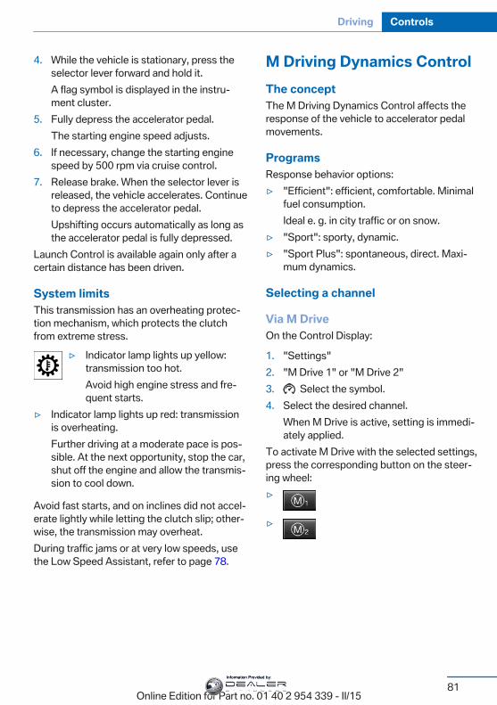
4. While the vehicle is stationary, press theselector lever forward and hold it.A flag symbol is displayed in the instru‐ment cluster.
5. Fully depress the accelerator pedal.The starting engine speed adjusts.
6. If necessary, change the starting enginespeed by 500 rpm via cruise control.
7. Release brake. When the selector lever isreleased, the vehicle accelerates. Continueto depress the accelerator pedal.Upshifting occurs automatically as long asthe accelerator pedal is fully depressed.
Launch Control is available again only after acertain distance has been driven.
System limitsThis transmission has an overheating protec‐tion mechanism, which protects the clutchfrom extreme stress.
▷ Indicator lamp lights up yellow:transmission too hot.Avoid high engine stress and fre‐quent starts.
▷ Indicator lamp lights up red: transmissionis overheating.Further driving at a moderate pace is pos‐sible. At the next opportunity, stop the car,shut off the engine and allow the transmis‐sion to cool down.
Avoid fast starts, and on inclines did not accel‐erate lightly while letting the clutch slip; other‐wise, the transmission may overheat.During traffic jams or at very low speeds, usethe Low Speed Assistant, refer to page 78.
M Driving Dynamics ControlThe conceptThe M Driving Dynamics Control affects theresponse of the vehicle to accelerator pedalmovements.
ProgramsResponse behavior options:▷ "Efficient": efficient, comfortable. Minimal
fuel consumption.Ideal e. g. in city traffic or on snow.
▷ "Sport": sporty, dynamic.▷ "Sport Plus": spontaneous, direct. Maxi‐
mum dynamics.
Selecting a channel
Via M DriveOn the Control Display:
1. "Settings"2. "M Drive 1" or "M Drive 2"3. Select the symbol.4. Select the desired channel.
When M Drive is active, setting is immedi‐ately applied.
To activate M Drive with the selected settings,press the corresponding button on the steer‐ing wheel:▷
▷
Seite 81
Driving Controls
81Online Edition for Part no. 01 40 2 954 339 - II/15
Information Provided by:
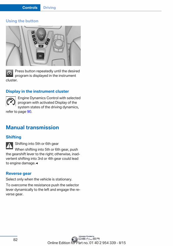
Using the button
Press button repeatedly until the desiredprogram is displayed in the instrument
cluster.
Display in the instrument clusterEngine Dynamics Control with selectedprogram with activated Display of thesystem states of the driving dynamics,
refer to page 90.
Manual transmissionShifting
Shifting into 5th or 6th gearWhen shifting into 5th or 6th gear, push
the gearshift lever to the right; otherwise, inad‐vertent shifting into 3rd or 4th gear could leadto engine damage.◀
Reverse gearSelect only when the vehicle is stationary.To overcome the resistance push the selectorlever dynamically to the left and engage the re‐verse gear.
Seite 82
Controls Driving
82Online Edition for Part no. 01 40 2 954 339 - II/15
Information Provided by:
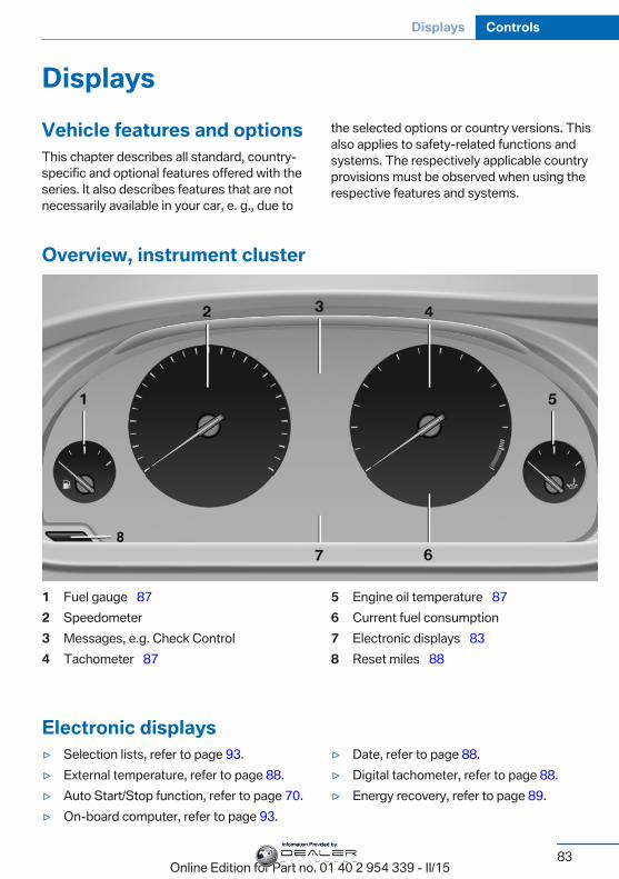
DisplaysVehicle features and optionsThis chapter describes all standard, country-specific and optional features offered with theseries. It also describes features that are notnecessarily available in your car, e. g., due to
the selected options or country versions. Thisalso applies to safety-related functions andsystems. The respectively applicable countryprovisions must be observed when using therespective features and systems.
Overview, instrument cluster
1 Fuel gauge 872 Speedometer3 Messages, e.g. Check Control4 Tachometer 87
5 Engine oil temperature 876 Current fuel consumption7 Electronic displays 838 Reset miles 88
Electronic displays▷ Selection lists, refer to page 93.▷ External temperature, refer to page 88.▷ Auto Start/Stop function, refer to page 70.▷ On-board computer, refer to page 93.
▷ Date, refer to page 88.▷ Digital tachometer, refer to page 88.▷ Energy recovery, refer to page 89.
Seite 83
Displays Controls
83Online Edition for Part no. 01 40 2 954 339 - II/15
Information Provided by:
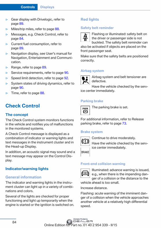
▷ Gear display with Drivelogic, refer topage 89.
▷ Miles/trip miles, refer to page 88.▷ Messages, e.g. Check Control, refer to
page 84.▷ Current fuel consumption, refer to
page 89.▷ Navigation display, see User's manual for
Navigation, Entertainment and Communi‐cation.
▷ Range, refer to page 89.▷ Service requirements, refer to page 90.▷ Speed limit detection, refer to page 92.▷ System states of driving dynamics, refer to
page 90.▷ Time, refer to page 88.
Check ControlThe conceptThe Check Control system monitors functionsin the vehicle and notifies you of malfunctionsin the monitored systems.A Check Control message is displayed as acombination of indicator or warning lights andtext messages in the instrument cluster and inthe Head-up Display.In addition, an acoustic signal may sound and atext message may appear on the Control Dis‐play.
Indicator/warning lights
General informationThe indicator and warning lights in the instru‐ment cluster can light up in a variety of combi‐nations and colors.Several of the lights are checked for properfunctioning and light up temporarily when theengine is started or the ignition is switched on.
Red lights
Safety belt reminderFlashing or illuminated: safety belt onthe driver or passenger side is notbuckled. The safety belt reminder can
also be activated if objects are placed on thefront passenger seat.Make sure that the safety belts are positionedcorrectly.
Airbag systemAirbag system and belt tensioner aredefective.Have the vehicle checked by the serv‐
ice center immediately.
Parking brakeThe parking brake is set.
For additional information, refer to Releaseparking brake, refer to page 73.
Brake systemContinue to drive moderately.Have the vehicle checked by the serv‐ice center immediately.
Front-end collision warningIlluminated: advance warning is issued,e.g., when there is the impending dan‐ger of a collision or the distance to the
vehicle ahead is too small.Increase distance.Flashing: acute warning of the imminent dan‐ger of a collision when the vehicle approachesanother vehicle at a relatively high differentialspeed.
Seite 84
Controls Displays
84Online Edition for Part no. 01 40 2 954 339 - II/15
Information Provided by:
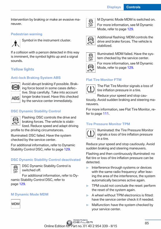
Intervention by braking or make an evasive ma‐neuver.
Pedestrian warningSymbol in the instrument cluster.
If a collision with a person detected in this wayis imminent, the symbol lights up and a signalsounds.
Yellow lights
Anti-lock Braking System ABSAvoid abrupt braking if possible. Brak‐ing force boost in some cases defec‐tive. Stop carefully. Take into accountlonger brake travel. Have this checkedby the service center immediately.
DSC Dynamic Stability ControlFlashing: DSC controls the drive andbraking forces. The vehicle is stabi‐lized. Reduce speed and adapt driving
profile to the driving circumstances.Illuminated: DSC failed. Have the systemchecked by the service center.For additional information, refer to DynamicStability Control DSC, refer to page 129.
DSC Dynamic Stability Control deactivatedDSC Dynamic Stability Control isswitched off.For additional information, refer to Dy‐
namic Stability Control DSC, refer topage 129.
M Dynamic Mode MDM
M Dynamic Mode MDM is switched on.For more information, see M DynamicMode, refer to page 129.
Additional flashing: MDM controls thedrive and brake forces. The vehicle isstabilized.
Illuminated: MDM failed. Have the sys‐tem checked by the service center.For more information, see M DynamicMode, refer to page 129.
Flat Tire Monitor FTMThe Flat Tire Monitor signals a loss oftire inflation pressure in a tire.Reduce your speed and stop cau‐
tiously. Avoid sudden braking and steering ma‐neuvers.For more information, see Flat Tire Monitor, re‐fer to page 111.
Tire Pressure Monitor TPMIlluminated: the Tire Pressure Monitorsignals a loss of tire inflation pressurein a tire.
Reduce your speed and stop cautiously. Avoidsudden braking and steering maneuvers.Flashing and then continuously illuminated: noflat tire or loss of tire inflation pressure can bedetected.▷ Interference through systems or devices
with the same radio frequency: after leav‐ing the area of the interference, the systemautomatically becomes active again.
▷ TPM could not conclude the reset: performthe reset of the system again.
▷ A wheel without TPM electronics is fitted:have the service center check it if needed.
▷ Malfunction: have the system checked byyour service center.
Seite 85
Displays Controls
85Online Edition for Part no. 01 40 2 954 339 - II/15
Information Provided by:
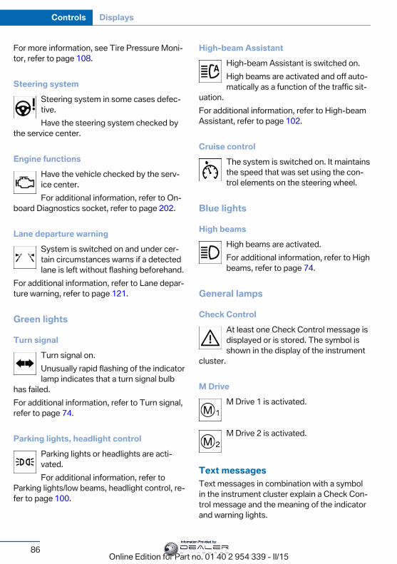
For more information, see Tire Pressure Moni‐tor, refer to page 108.
Steering systemSteering system in some cases defec‐tive.Have the steering system checked by
the service center.
Engine functionsHave the vehicle checked by the serv‐ice center.For additional information, refer to On-
board Diagnostics socket, refer to page 202.
Lane departure warningSystem is switched on and under cer‐tain circumstances warns if a detectedlane is left without flashing beforehand.
For additional information, refer to Lane depar‐ture warning, refer to page 121.
Green lights
Turn signalTurn signal on.Unusually rapid flashing of the indicatorlamp indicates that a turn signal bulb
has failed.For additional information, refer to Turn signal,refer to page 74.
Parking lights, headlight controlParking lights or headlights are acti‐vated.For additional information, refer to
Parking lights/low beams, headlight control, re‐fer to page 100.
High-beam AssistantHigh-beam Assistant is switched on.High beams are activated and off auto‐matically as a function of the traffic sit‐
uation.For additional information, refer to High-beamAssistant, refer to page 102.
Cruise controlThe system is switched on. It maintainsthe speed that was set using the con‐trol elements on the steering wheel.
Blue lights
High beamsHigh beams are activated.For additional information, refer to Highbeams, refer to page 74.
General lamps
Check ControlAt least one Check Control message isdisplayed or is stored. The symbol isshown in the display of the instrument
cluster.
M DriveM Drive 1 is activated.
M Drive 2 is activated.
Text messagesText messages in combination with a symbolin the instrument cluster explain a Check Con‐trol message and the meaning of the indicatorand warning lights.
Seite 86
Controls Displays
86Online Edition for Part no. 01 40 2 954 339 - II/15
Information Provided by:
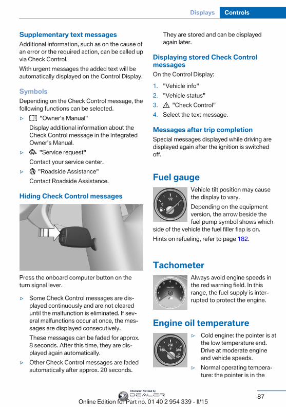
Supplementary text messagesAdditional information, such as on the cause ofan error or the required action, can be called upvia Check Control.With urgent messages the added text will beautomatically displayed on the Control Display.
SymbolsDepending on the Check Control message, thefollowing functions can be selected.▷ "Owner's Manual"
Display additional information about theCheck Control message in the IntegratedOwner's Manual.
▷ "Service request"Contact your service center.
▷ "Roadside Assistance"Contact Roadside Assistance.
Hiding Check Control messages
Press the onboard computer button on theturn signal lever.
▷ Some Check Control messages are dis‐played continuously and are not cleareduntil the malfunction is eliminated. If sev‐eral malfunctions occur at once, the mes‐sages are displayed consecutively.These messages can be faded for approx.8 seconds. After this time, they are dis‐played again automatically.
▷ Other Check Control messages are fadedautomatically after approx. 20 seconds.
They are stored and can be displayedagain later.
Displaying stored Check ControlmessagesOn the Control Display:
1. "Vehicle info"2. "Vehicle status"3. "Check Control"4. Select the text message.
Messages after trip completionSpecial messages displayed while driving aredisplayed again after the ignition is switchedoff.
Fuel gaugeVehicle tilt position may causethe display to vary.Depending on the equipmentversion, the arrow beside thefuel pump symbol shows which
side of the vehicle the fuel filler flap is on.Hints on refueling, refer to page 182.
TachometerAlways avoid engine speeds inthe red warning field. In thisrange, the fuel supply is inter‐rupted to protect the engine.
Engine oil temperature▷ Cold engine: the pointer is at
the low temperature end.Drive at moderate engineand vehicle speeds.
▷ Normal operating tempera‐ture: the pointer is in the
Seite 87
Displays Controls
87Online Edition for Part no. 01 40 2 954 339 - II/15
Information Provided by:
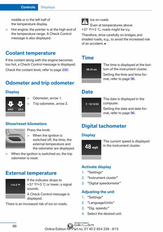
middle or in the left half ofthe temperature display.
▷ Hot engine: the pointer is at the high end ofthe temperature range. A Check Controlmessage is also displayed.
Coolant temperatureIf the coolant along with the engine becomestoo hot, a Check Control message is displayed.Check the coolant level, refer to page 200.
Odometer and trip odometerDisplay
▷ Odometer, arrow 1.▷ Trip odometer, arrow 2.
Show/reset kilometersPress the knob.▷ When the ignition is
switched off, the time, theexternal temperature andthe odometer are displayed.
▷ When the ignition is switched on, the tripodometer is reset.
External temperatureIf the indicator drops to+37 ℉/+3 ℃ or lower, a signalsounds.A Check Control message isdisplayed.
There is an increased risk of ice on roads.
Ice on roadsEven at temperatures above
+37 ℉/+3 ℃, roads might be icy.Therefore, drive carefully on bridges andshaded roads, e.g., to avoid the increased riskof an accident.◀
TimeThe time is displayed at the bot‐tom of the instrument cluster.Setting the time and time for‐mat, refer to page 96.
DateThe date is displayed in thecomputer.Setting the date and date for‐mat, refer to page 96.
Digital tachometerDisplay
The current speed is displayedin the instrument cluster.
Activate display1. "Settings"2. "Instrument cluster"3. "Digital speedometer"
Adjusting the unit1. "Settings"2. "Language/Units"3. "Dig. speedo:"4. Select the desired unit.
Seite 88
Controls Displays
88Online Edition for Part no. 01 40 2 954 339 - II/15
Information Provided by:
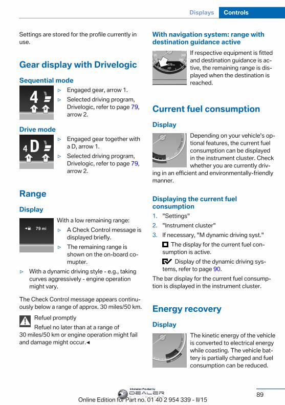
Settings are stored for the profile currently inuse.
Gear display with DrivelogicSequential mode
▷ Engaged gear, arrow 1.▷ Selected driving program,
Drivelogic, refer to page 79,arrow 2.
Drive mode▷ Engaged gear together with
a D, arrow 1.▷ Selected driving program,
Drivelogic, refer to page 79,arrow 2.
RangeDisplay
With a low remaining range:▷ A Check Control message is
displayed briefly.▷ The remaining range is
shown on the on-board co‐mupter.
▷ With a dynamic driving style - e.g., takingcurves aggressively - engine operationmight vary.
The Check Control message appears continu‐ously below a range of approx. 30 miles/50 km.
Refuel promptlyRefuel no later than at a range of
30 miles/50 km or engine operation might failand damage might occur.◀
With navigation system: range withdestination guidance active
If respective equipment is fittedand destination guidance is ac‐tive, the remaining range is dis‐played when the destination isreached.
Current fuel consumptionDisplay
Depending on your vehicle's op‐tional features, the current fuelconsumption can be displayedin the instrument cluster. Checkwhether you are currently driv‐
ing in an efficient and environmentally-friendlymanner.
Displaying the current fuelconsumption1. "Settings"2. "Instrument cluster"3. If necessary, "M dynamic driving syst."
The display for the current fuel con‐sumption is active.
Display of the dynamic driving sys‐tems, refer to page 90.
The bar display for the current fuel consump‐tion is displayed in the instrument cluster.
Energy recoveryDisplay
The kinetic energy of the vehicleis converted to electrical energywhile coasting. The vehicle bat‐tery is partially charged and fuelconsumption can be reduced.
Seite 89
Displays Controls
89Online Edition for Part no. 01 40 2 954 339 - II/15
Information Provided by:
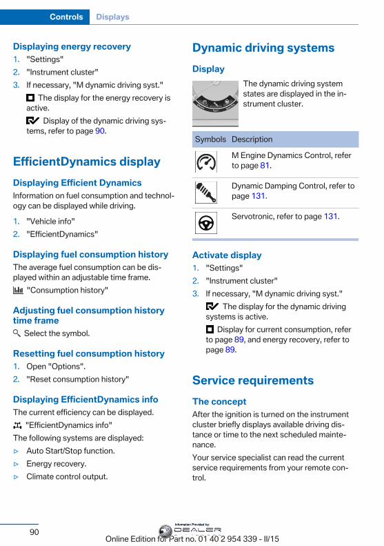
Displaying energy recovery1. "Settings"2. "Instrument cluster"3. If necessary, "M dynamic driving syst."
The display for the energy recovery isactive.
Display of the dynamic driving sys‐tems, refer to page 90.
EfficientDynamics displayDisplaying Efficient DynamicsInformation on fuel consumption and technol‐ogy can be displayed while driving.
1. "Vehicle info"2. "EfficientDynamics"
Displaying fuel consumption historyThe average fuel consumption can be dis‐played within an adjustable time frame.
"Consumption history"
Adjusting fuel consumption historytime frame
Select the symbol.
Resetting fuel consumption history1. Open "Options".2. "Reset consumption history"
Displaying EfficientDynamics infoThe current efficiency can be displayed.
"EfficientDynamics info"The following systems are displayed:▷ Auto Start/Stop function.▷ Energy recovery.▷ Climate control output.
Dynamic driving systemsDisplay
The dynamic driving systemstates are displayed in the in‐strument cluster.
Symbols Description
M Engine Dynamics Control, referto page 81.
Dynamic Damping Control, refer topage 131.
Servotronic, refer to page 131.
Activate display1. "Settings"2. "Instrument cluster"3. If necessary, "M dynamic driving syst."
The display for the dynamic drivingsystems is active.
Display for current consumption, referto page 89, and energy recovery, refer topage 89.
Service requirementsThe conceptAfter the ignition is turned on the instrumentcluster briefly displays available driving dis‐tance or time to the next scheduled mainte‐nance.Your service specialist can read the currentservice requirements from your remote con‐trol.
Seite 90
Controls Displays
90Online Edition for Part no. 01 40 2 954 339 - II/15
Information Provided by:
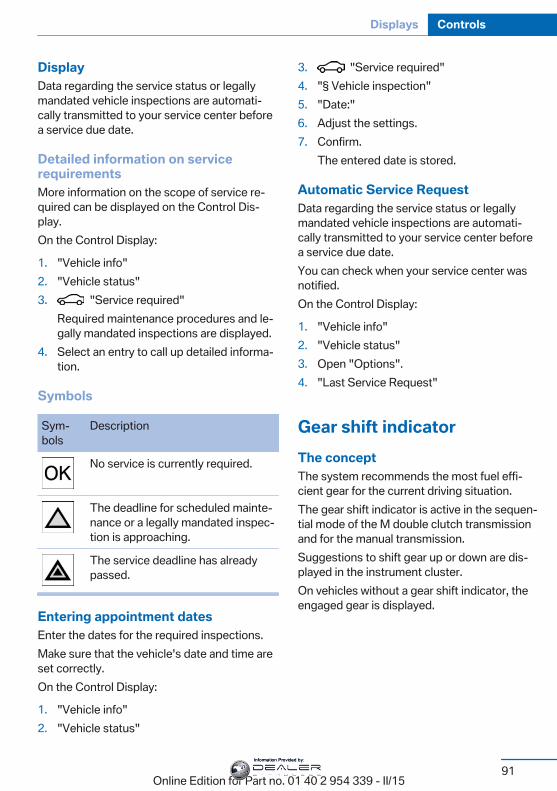
DisplayData regarding the service status or legallymandated vehicle inspections are automati‐cally transmitted to your service center beforea service due date.
Detailed information on servicerequirementsMore information on the scope of service re‐quired can be displayed on the Control Dis‐play.On the Control Display:
1. "Vehicle info"2. "Vehicle status"3. "Service required"
Required maintenance procedures and le‐gally mandated inspections are displayed.
4. Select an entry to call up detailed informa‐tion.
Symbols
Sym‐bols
Description
No service is currently required.
The deadline for scheduled mainte‐nance or a legally mandated inspec‐tion is approaching.
The service deadline has alreadypassed.
Entering appointment datesEnter the dates for the required inspections.Make sure that the vehicle's date and time areset correctly.On the Control Display:
1. "Vehicle info"2. "Vehicle status"
3. "Service required"4. "§ Vehicle inspection"5. "Date:"6. Adjust the settings.7. Confirm.
The entered date is stored.
Automatic Service RequestData regarding the service status or legallymandated vehicle inspections are automati‐cally transmitted to your service center beforea service due date.You can check when your service center wasnotified.On the Control Display:
1. "Vehicle info"2. "Vehicle status"3. Open "Options".4. "Last Service Request"
Gear shift indicatorThe conceptThe system recommends the most fuel effi‐cient gear for the current driving situation.The gear shift indicator is active in the sequen‐tial mode of the M double clutch transmissionand for the manual transmission.Suggestions to shift gear up or down are dis‐played in the instrument cluster.On vehicles without a gear shift indicator, theengaged gear is displayed.
Seite 91
Displays Controls
91Online Edition for Part no. 01 40 2 954 339 - II/15
Information Provided by:
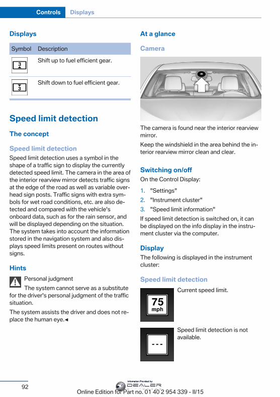
Displays
Symbol Description
Shift up to fuel efficient gear.
Shift down to fuel efficient gear.
Speed limit detectionThe concept
Speed limit detectionSpeed limit detection uses a symbol in theshape of a traffic sign to display the currentlydetected speed limit. The camera in the area ofthe interior rearview mirror detects traffic signsat the edge of the road as well as variable over‐head sign posts. Traffic signs with extra sym‐bols for wet road conditions, etc. are also de‐tected and compared with the vehicle'sonboard data, such as for the rain sensor, andwill be displayed depending on the situation.The system takes into account the informationstored in the navigation system and also dis‐plays speed limits present on routes withoutsigns.
HintsPersonal judgmentThe system cannot serve as a substitute
for the driver's personal judgment of the trafficsituation.The system assists the driver and does not re‐place the human eye.◀
At a glance
Camera
The camera is found near the interior rearviewmirror.Keep the windshield in the area behind the in‐terior rearview mirror clean and clear.
Switching on/offOn the Control Display:
1. "Settings"2. "Instrument cluster"3. "Speed limit information"If speed limit detection is switched on, it canbe displayed on the info display in the instru‐ment cluster via the computer.
DisplayThe following is displayed in the instrumentcluster:
Speed limit detectionCurrent speed limit.
Speed limit detection is notavailable.
Seite 92
Controls Displays
92Online Edition for Part no. 01 40 2 954 339 - II/15
Information Provided by:
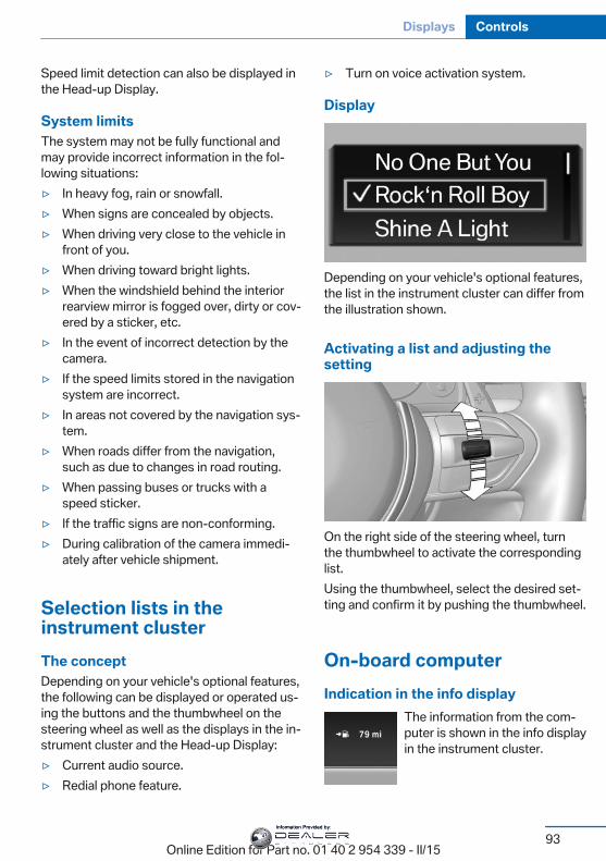
Speed limit detection can also be displayed inthe Head-up Display.
System limitsThe system may not be fully functional andmay provide incorrect information in the fol‐lowing situations:▷ In heavy fog, rain or snowfall.▷ When signs are concealed by objects.▷ When driving very close to the vehicle in
front of you.▷ When driving toward bright lights.▷ When the windshield behind the interior
rearview mirror is fogged over, dirty or cov‐ered by a sticker, etc.
▷ In the event of incorrect detection by thecamera.
▷ If the speed limits stored in the navigationsystem are incorrect.
▷ In areas not covered by the navigation sys‐tem.
▷ When roads differ from the navigation,such as due to changes in road routing.
▷ When passing buses or trucks with aspeed sticker.
▷ If the traffic signs are non-conforming.▷ During calibration of the camera immedi‐
ately after vehicle shipment.
Selection lists in theinstrument clusterThe conceptDepending on your vehicle's optional features,the following can be displayed or operated us‐ing the buttons and the thumbwheel on thesteering wheel as well as the displays in the in‐strument cluster and the Head-up Display:▷ Current audio source.▷ Redial phone feature.
▷ Turn on voice activation system.
Display
Depending on your vehicle's optional features,the list in the instrument cluster can differ fromthe illustration shown.
Activating a list and adjusting thesetting
On the right side of the steering wheel, turnthe thumbwheel to activate the correspondinglist.Using the thumbwheel, select the desired set‐ting and confirm it by pushing the thumbwheel.
On-board computerIndication in the info display
The information from the com‐puter is shown in the info displayin the instrument cluster.
Seite 93
Displays Controls
93Online Edition for Part no. 01 40 2 954 339 - II/15
Information Provided by:
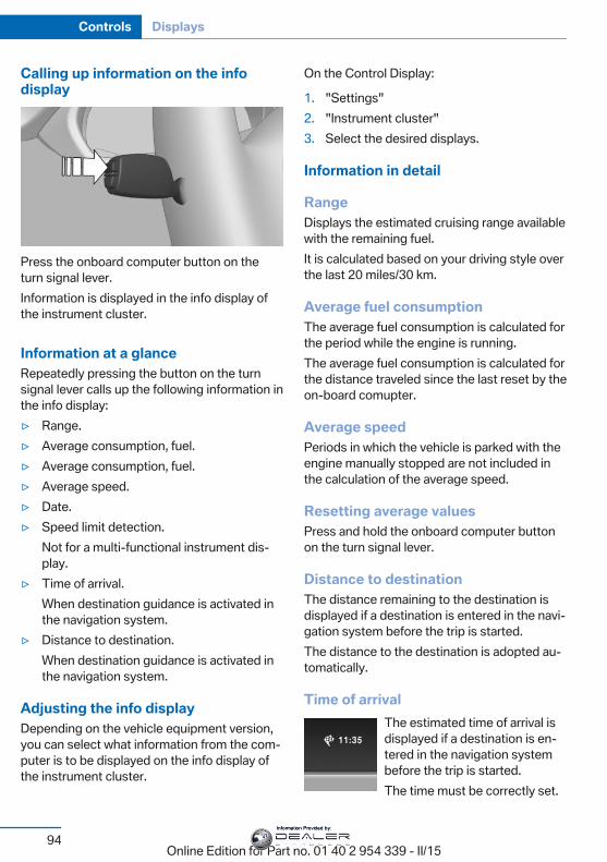
Calling up information on the infodisplay
Press the onboard computer button on theturn signal lever.Information is displayed in the info display ofthe instrument cluster.
Information at a glanceRepeatedly pressing the button on the turnsignal lever calls up the following information inthe info display:▷ Range.▷ Average consumption, fuel.▷ Average consumption, fuel.▷ Average speed.▷ Date.▷ Speed limit detection.
Not for a multi-functional instrument dis‐play.
▷ Time of arrival.When destination guidance is activated inthe navigation system.
▷ Distance to destination.When destination guidance is activated inthe navigation system.
Adjusting the info displayDepending on the vehicle equipment version,you can select what information from the com‐puter is to be displayed on the info display ofthe instrument cluster.
On the Control Display:
1. "Settings"2. "Instrument cluster"3. Select the desired displays.
Information in detail
RangeDisplays the estimated cruising range availablewith the remaining fuel.It is calculated based on your driving style overthe last 20 miles/30 km.
Average fuel consumptionThe average fuel consumption is calculated forthe period while the engine is running.The average fuel consumption is calculated forthe distance traveled since the last reset by theon-board comupter.
Average speedPeriods in which the vehicle is parked with theengine manually stopped are not included inthe calculation of the average speed.
Resetting average valuesPress and hold the onboard computer buttonon the turn signal lever.
Distance to destinationThe distance remaining to the destination isdisplayed if a destination is entered in the navi‐gation system before the trip is started.The distance to the destination is adopted au‐tomatically.
Time of arrivalThe estimated time of arrival isdisplayed if a destination is en‐tered in the navigation systembefore the trip is started.The time must be correctly set.
Seite 94
Controls Displays
94Online Edition for Part no. 01 40 2 954 339 - II/15
Information Provided by:
Speed limit detectionDescription of the speed limit detection, referto page 92, function.
Trip computerThe vehicle features two types of board com‐puters.▷ "Onboard info": the values can be reset as
often as necessary.▷ "Trip computer": the values provide an
overview of the current trip.
Resetting the trip computerOn the Control Display:
1. "Vehicle info"2. "Trip computer"3. "Reset": all values are reset.
"Automatically reset": all values are resetapprox. 4 hours after the vehicle came to astandstill.
Display on the Control DisplayDisplay the computer or trip computer on theControl Display.
1. "Vehicle info"2. "Onboard info" or "Trip computer"
Resetting the fuel consumption orspeedOn the Control Display:
1. "Vehicle info"2. "Onboard info"3. "Consumpt." or "Speed"4. "Yes"
Sport displaysThe conceptOn the Control Display, the current values forperformance and torque can be displayed ifthe vehicle is appropriately equipped.
Displaying sport displays on theControl Display1. "Vehicle info"2. "Sport displays"
Speed warningThe conceptDisplays a speed, when reached, should causea warning to be issued.The warning is repeated if the vehicle speeddrops below the set speed once by at least3 mph/5 km/h.
Displaying, setting or changing thespeed warningOn the Control Display:
1. "Settings"2. "Speed"3. "Warning at:"4. Turn the controller until the desired speed
is displayed.5. Press the controller.Speed warning is stored.
Activating/deactivating the speedwarningOn the Control Display:
1. "Settings"2. "Speed"3. "Warning"4. Press the controller.
Seite 95
Displays Controls
95Online Edition for Part no. 01 40 2 954 339 - II/15
Information Provided by:

Setting your current speed as thespeed warningOn the Control Display:
1. "Settings"2. "Speed"3. "Select current speed"4. Press the controller.
The current vehicle speed is stored as thespeed warning.
Settings on the ControlDisplayTime
Setting the time zone1. "Settings"2. "Time/Date"3. "Time zone:"4. Select the desired time zone.The time zone is stored.
Setting the time1. "Settings"2. "Time/Date"3. "Time:"4. Turn the controller until the desired hours
are displayed.5. Press the controller.6. Turn the controller until the desired mi‐
nutes are displayed.7. Press the controller.The time is stored.
Setting the time format1. "Settings"2. "Time/Date"
3. "Format:"4. Select the desired format.The time format is stored.
Automatic time settingDepending on your vehicle's optional features,the time, date and, if needed, the time zone areupdated automatically.
1. "Settings"2. "Time/Date"3. "Auto time set"
Date
Setting the date1. "Settings"2. "Time/Date"3. "Date:"4. Turn the controller until the desired day is
displayed.5. Press the controller.6. Make the necessary settings for the month
and year.The date is stored.
Setting the date format1. "Settings"2. "Time/Date"3. "Format:"4. Select the desired format.The date format is stored.
Language
Setting the languageTo set the language on the Control Display:
1. "Settings"2. "Language/Units"3. "Language:"4. Select the desired language.
Seite 96
Controls Displays
96Online Edition for Part no. 01 40 2 954 339 - II/15
Information Provided by:
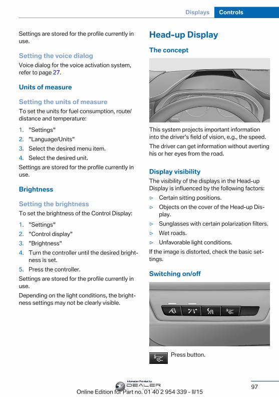
Settings are stored for the profile currently inuse.
Setting the voice dialogVoice dialog for the voice activation system,refer to page 27.
Units of measure
Setting the units of measureTo set the units for fuel consumption, route/distance and temperature:
1. "Settings"2. "Language/Units"3. Select the desired menu item.4. Select the desired unit.Settings are stored for the profile currently inuse.
Brightness
Setting the brightnessTo set the brightness of the Control Display:
1. "Settings"2. "Control display"3. "Brightness"4. Turn the controller until the desired bright‐
ness is set.5. Press the controller.Settings are stored for the profile currently inuse.Depending on the light conditions, the bright‐ness settings may not be clearly visible.
Head-up DisplayThe concept
This system projects important informationinto the driver's field of vision, e.g., the speed.The driver can get information without avertinghis or her eyes from the road.
Display visibilityThe visibility of the displays in the Head-upDisplay is influenced by the following factors:▷ Certain sitting positions.▷ Objects on the cover of the Head-up Dis‐
play.▷ Sunglasses with certain polarization filters.▷ Wet roads.▷ Unfavorable light conditions.If the image is distorted, check the basic set‐tings.
Switching on/off
Press button.
Seite 97
Displays Controls
97Online Edition for Part no. 01 40 2 954 339 - II/15
Information Provided by:
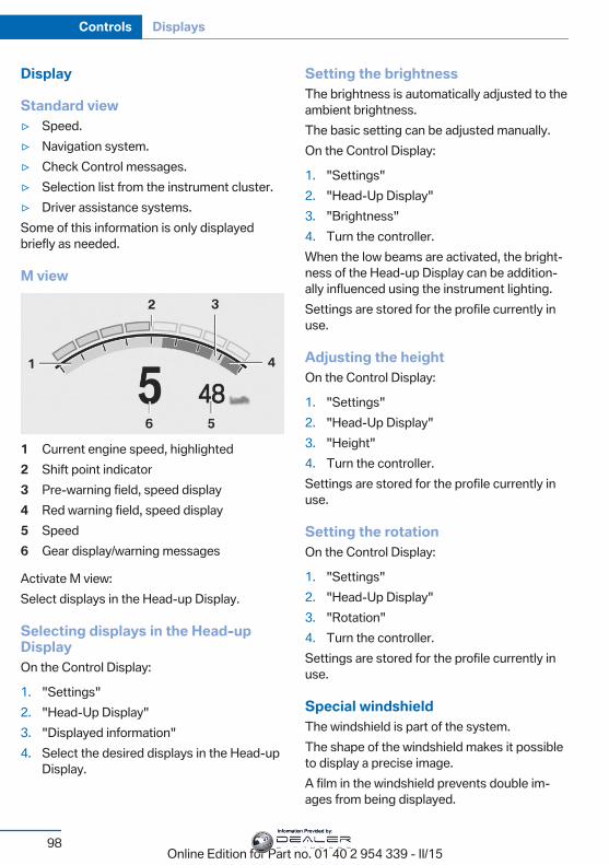
Display
Standard view▷ Speed.▷ Navigation system.▷ Check Control messages.▷ Selection list from the instrument cluster.▷ Driver assistance systems.Some of this information is only displayedbriefly as needed.
M view
1 Current engine speed, highlighted2 Shift point indicator3 Pre-warning field, speed display4 Red warning field, speed display5 Speed6 Gear display/warning messages
Activate M view:Select displays in the Head-up Display.
Selecting displays in the Head-upDisplayOn the Control Display:
1. "Settings"2. "Head-Up Display"3. "Displayed information"4. Select the desired displays in the Head-up
Display.
Setting the brightnessThe brightness is automatically adjusted to theambient brightness.The basic setting can be adjusted manually.On the Control Display:
1. "Settings"2. "Head-Up Display"3. "Brightness"4. Turn the controller.When the low beams are activated, the bright‐ness of the Head-up Display can be addition‐ally influenced using the instrument lighting.Settings are stored for the profile currently inuse.
Adjusting the heightOn the Control Display:
1. "Settings"2. "Head-Up Display"3. "Height"4. Turn the controller.Settings are stored for the profile currently inuse.
Setting the rotationOn the Control Display:
1. "Settings"2. "Head-Up Display"3. "Rotation"4. Turn the controller.Settings are stored for the profile currently inuse.
Special windshieldThe windshield is part of the system.The shape of the windshield makes it possibleto display a precise image.A film in the windshield prevents double im‐ages from being displayed.
Seite 98
Controls Displays
98Online Edition for Part no. 01 40 2 954 339 - II/15
Information Provided by:
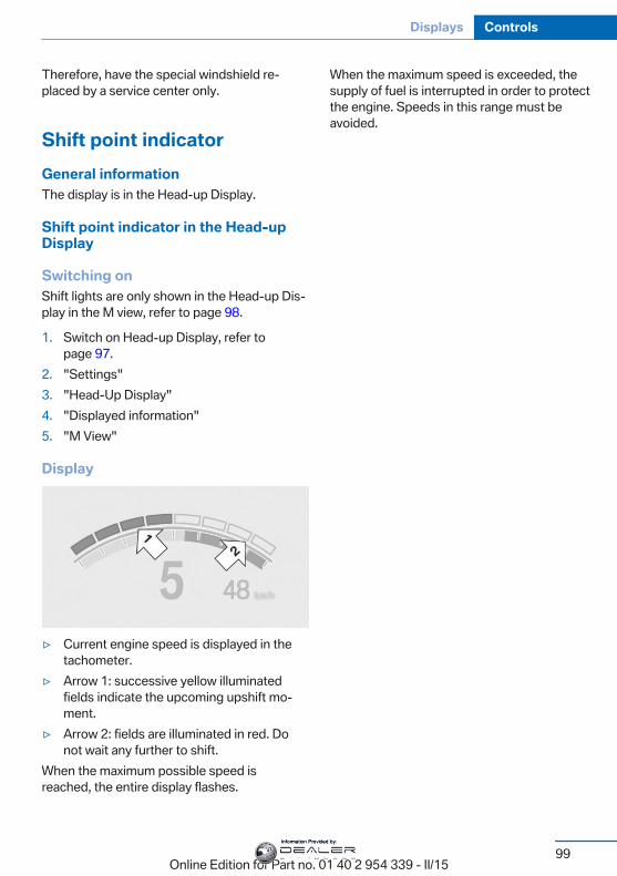
Therefore, have the special windshield re‐placed by a service center only.
Shift point indicatorGeneral informationThe display is in the Head-up Display.
Shift point indicator in the Head-upDisplay
Switching onShift lights are only shown in the Head-up Dis‐play in the M view, refer to page 98.
1. Switch on Head-up Display, refer topage 97.
2. "Settings"3. "Head-Up Display"4. "Displayed information"5. "M View"
Display
▷ Current engine speed is displayed in thetachometer.
▷ Arrow 1: successive yellow illuminatedfields indicate the upcoming upshift mo‐ment.
▷ Arrow 2: fields are illuminated in red. Donot wait any further to shift.
When the maximum possible speed isreached, the entire display flashes.
When the maximum speed is exceeded, thesupply of fuel is interrupted in order to protectthe engine. Speeds in this range must beavoided.
Seite 99
Displays Controls
99Online Edition for Part no. 01 40 2 954 339 - II/15
Information Provided by:
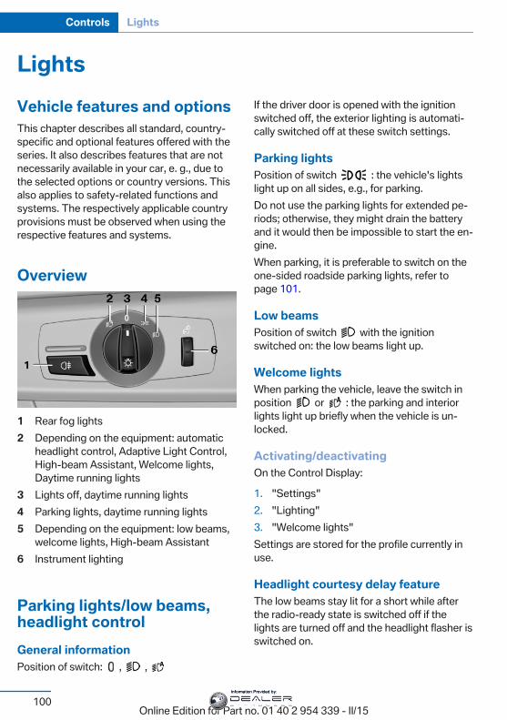
LightsVehicle features and optionsThis chapter describes all standard, country-specific and optional features offered with theseries. It also describes features that are notnecessarily available in your car, e. g., due tothe selected options or country versions. Thisalso applies to safety-related functions andsystems. The respectively applicable countryprovisions must be observed when using therespective features and systems.
Overview
1 Rear fog lights2 Depending on the equipment: automatic
headlight control, Adaptive Light Control,High-beam Assistant, Welcome lights,Daytime running lights
3 Lights off, daytime running lights4 Parking lights, daytime running lights5 Depending on the equipment: low beams,
welcome lights, High-beam Assistant6 Instrument lighting
Parking lights/low beams,headlight controlGeneral informationPosition of switch: , ,
If the driver door is opened with the ignitionswitched off, the exterior lighting is automati‐cally switched off at these switch settings.
Parking lightsPosition of switch : the vehicle's lightslight up on all sides, e.g., for parking.Do not use the parking lights for extended pe‐riods; otherwise, they might drain the batteryand it would then be impossible to start the en‐gine.When parking, it is preferable to switch on theone-sided roadside parking lights, refer topage 101.
Low beamsPosition of switch with the ignitionswitched on: the low beams light up.
Welcome lightsWhen parking the vehicle, leave the switch inposition or : the parking and interiorlights light up briefly when the vehicle is un‐locked.
Activating/deactivatingOn the Control Display:
1. "Settings"2. "Lighting"3. "Welcome lights"Settings are stored for the profile currently inuse.
Headlight courtesy delay featureThe low beams stay lit for a short while afterthe radio-ready state is switched off if thelights are turned off and the headlight flasher isswitched on.
Seite 100
Controls Lights
100Online Edition for Part no. 01 40 2 954 339 - II/15
Information Provided by:
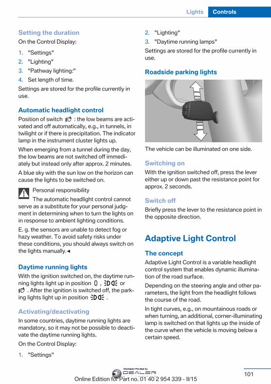
Setting the durationOn the Control Display:
1. "Settings"2. "Lighting"3. "Pathway lighting:"4. Set length of time.Settings are stored for the profile currently inuse.
Automatic headlight controlPosition of switch : the low beams are acti‐vated and off automatically, e.g., in tunnels, intwilight or if there is precipitation. The indicatorlamp in the instrument cluster lights up.When emerging from a tunnel during the day,the low beams are not switched off immedi‐ately but instead only after approx. 2 minutes.A blue sky with the sun low on the horizon cancause the lights to be switched on.
Personal responsibilityThe automatic headlight control cannot
serve as a substitute for your personal judg‐ment in determining when to turn the lights onin response to ambient lighting conditions.E. g. the sensors are unable to detect fog orhazy weather. To avoid safety risks underthese conditions, you should always switch onthe lights manually.◀
Daytime running lightsWith the ignition switched on, the daytime run‐ning lights light up in position , or
. After the ignition is switched off, the park‐ing lights light up in position .
Activating/deactivatingIn some countries, daytime running lights aremandatory, so it may not be possible to deacti‐vate the daytime running lights.On the Control Display:
1. "Settings"
2. "Lighting"3. "Daytime running lamps"Settings are stored for the profile currently inuse.
Roadside parking lights
The vehicle can be illuminated on one side.
Switching onWith the ignition switched off, press the levereither up or down past the resistance point forapprox. 2 seconds.
Switch offBriefly press the lever to the resistance point inthe opposite direction.
Adaptive Light ControlThe conceptAdaptive Light Control is a variable headlightcontrol system that enables dynamic illumina‐tion of the road surface.Depending on the steering angle and other pa‐rameters, the light from the headlight followsthe course of the road.In tight curves, e.g., on mountainous roads orwhen turning, an additional, corner-illuminatinglamp is switched on that lights up the inside ofthe curve when the vehicle is moving below acertain speed.
Seite 101
Lights Controls
101Online Edition for Part no. 01 40 2 954 339 - II/15
Information Provided by:
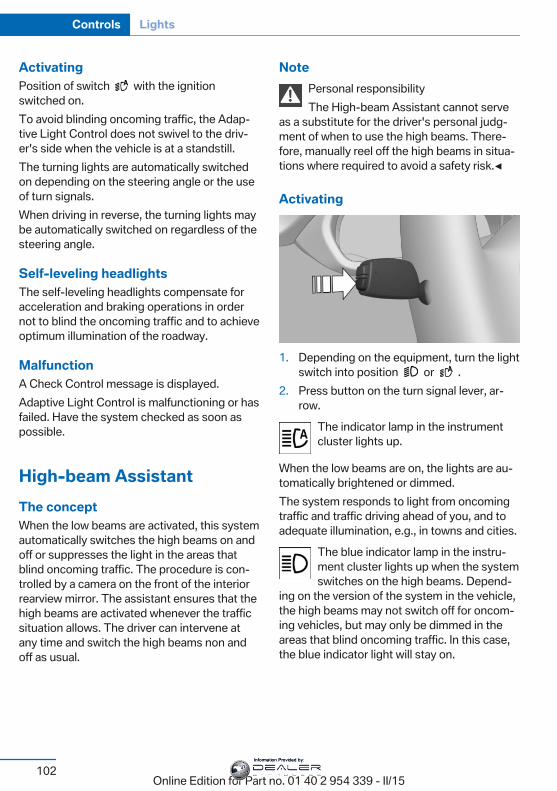
ActivatingPosition of switch with the ignitionswitched on.To avoid blinding oncoming traffic, the Adap‐tive Light Control does not swivel to the driv‐er's side when the vehicle is at a standstill.The turning lights are automatically switchedon depending on the steering angle or the useof turn signals.When driving in reverse, the turning lights maybe automatically switched on regardless of thesteering angle.
Self-leveling headlightsThe self-leveling headlights compensate foracceleration and braking operations in ordernot to blind the oncoming traffic and to achieveoptimum illumination of the roadway.
MalfunctionA Check Control message is displayed.Adaptive Light Control is malfunctioning or hasfailed. Have the system checked as soon aspossible.
High-beam AssistantThe conceptWhen the low beams are activated, this systemautomatically switches the high beams on andoff or suppresses the light in the areas thatblind oncoming traffic. The procedure is con‐trolled by a camera on the front of the interiorrearview mirror. The assistant ensures that thehigh beams are activated whenever the trafficsituation allows. The driver can intervene atany time and switch the high beams non andoff as usual.
NotePersonal responsibilityThe High-beam Assistant cannot serve
as a substitute for the driver's personal judg‐ment of when to use the high beams. There‐fore, manually reel off the high beams in situa‐tions where required to avoid a safety risk.◀
Activating
1. Depending on the equipment, turn the lightswitch into position or .
2. Press button on the turn signal lever, ar‐row.
The indicator lamp in the instrumentcluster lights up.
When the low beams are on, the lights are au‐tomatically brightened or dimmed.The system responds to light from oncomingtraffic and traffic driving ahead of you, and toadequate illumination, e.g., in towns and cities.
The blue indicator lamp in the instru‐ment cluster lights up when the systemswitches on the high beams. Depend‐
ing on the version of the system in the vehicle,the high beams may not switch off for oncom‐ing vehicles, but may only be dimmed in theareas that blind oncoming traffic. In this case,the blue indicator light will stay on.
Seite 102
Controls Lights
102Online Edition for Part no. 01 40 2 954 339 - II/15
Information Provided by:
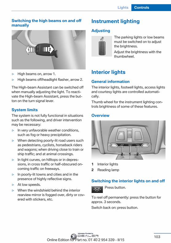
Switching the high beams on and offmanually
▷ High beams on, arrow 1.▷ High beams off/headlight flasher, arrow 2.
The High-beam Assistant can be switched offwhen manually adjusting the light. To reacti‐vate the High-beam Assistant, press the but‐ton on the turn signal lever.
System limitsThe system is not fully functional in situationssuch as the following, and driver interventionmay be necessary:▷ In very unfavorable weather conditions,
such as fog or heavy precipitation.▷ When detecting poorly-lit road users such
as pedestrians, cyclists, horseback ridersand wagons; when driving close to train orship traffic; and at animal crossings.
▷ In tight curves, on hilltops or in depres‐sions, in cross traffic or half-obscured on‐coming traffic on freeways.
▷ In poorly-lit towns and cities and in thepresence of highly reflective signs.
▷ At low speeds.▷ When the windshield behind the interior
rearview mirror is fogged over, dirty or cov‐ered with stickers, etc.
Instrument lightingAdjusting
The parking lights or low beamsmust be switched on to adjustthe brightness.Adjust the brightness with thethumbwheel.
Interior lightsGeneral informationThe interior lights, footwell lights, access lightsand courtesy lights are controlled automati‐cally.Thumb wheel for the instrument lighting con‐trols brightness of some of these features.
Overview
1 Interior lights2 Reading lamp
Switching the interior lights on and offPress button.
To reel off permanently: press the button forapprox. 3 seconds.Switch back on: press button.
Seite 103
Lights Controls
103Online Edition for Part no. 01 40 2 954 339 - II/15
Information Provided by:
Reading lightsPress button.
Reading lights are located at the front and rearnext to the interior lights.
Bang & Olufsen High End SurroundSound System
Adjusting speaker lightingSome speakers in the vehicle are illuminated.The lighting can be individually set.
1. "Settings"2. "Lighting"3. "B&O"4. Select the desired lighting setting.
▷ "Off": no lighting.▷ "Reduced": the speakers in the field of
view are faded while driving.▷ "On": the speakers are always illumi‐
nated.
Ambient lightDepending on the equipment, the lighting canbe individually adjusted in the interior for somelights.
Selecting color scheme1. "Settings"2. "Lighting"3. "Ambient:"4. Select desired setting.With a color scheme selected and welcomelights activated they illuminate in the line'scolor when vehicle is unlocked.
Setting the brightnessThe brightness of the ambient light can be ad‐justed via the thumbwheel for the instrumentlighting or on the Control Display.
1. "Settings"2. "Lighting"3. "Brightness:"4. Adjust the brightness.
Seite 104
Controls Lights
104Online Edition for Part no. 01 40 2 954 339 - II/15
Information Provided by:
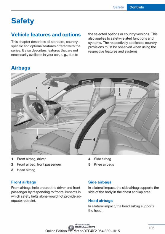
SafetyVehicle features and optionsThis chapter describes all standard, country-specific and optional features offered with theseries. It also describes features that are notnecessarily available in your car, e. g., due to
the selected options or country versions. Thisalso applies to safety-related functions andsystems. The respectively applicable countryprovisions must be observed when using therespective features and systems.
Airbags
1 Front airbag, driver2 Front airbag, front passenger3 Head airbag
4 Side airbag5 Knee airbags
Front airbagsFront airbags help protect the driver and frontpassenger by responding to frontal impacts inwhich safety belts alone would not provide ad‐equate restraint.
Side airbagsIn a lateral impact, the side airbag supports theside of the body in the chest and lap area.
Head airbagsIn a lateral impact, the head airbag supportsthe head.
Seite 105
Safety Controls
105Online Edition for Part no. 01 40 2 954 339 - II/15
Information Provided by:
Knee airbagThe knee airbag supports the legs in a frontalimpact.
Protective actionAirbags are not triggered in every impact situa‐tion, e.g., in less severe accidents or rear-endcollisions.
Information on how to ensure the optimalprotective effect of the airbags
▷ Keep at a distance from the airbags.▷ Always grasp the steering wheel on the
steering wheel rim, holding your hands atthe 3 o'clock and 9 o'clock positions, tokeep the risk of injury to your hands orarms as low as possible when the airbag istriggered.
▷ There should be no person, animals, or ob‐jects between an airbag and a person.
▷ Do not use the cover of the front airbag onthe front passenger side as a storage area.
▷ Dashboard and windshield on the frontpassenger side must stay clear - do not at‐tach adhesive labels or coverings and donot attach brackets or cables, e. g., for GPSdevices or' mobile phones.
▷ Make sure that the front passenger is sit‐ting correctly, i.e., keeps his or her feet andlegs in the footwell; otherwise, leg injuriesmight occur when front airbag is activated.
▷ Do not place slip covers, seat cushions orother objects on the front passenger seatthat are not approved specifically for seatswith integrated side airbags.
▷ Do not hang pieces of clothing, such asjackets, over the backrests.
▷ Make sure that occupants keep their headsaway from the side airbag and do not restagainst the head airbag; otherwise, injuriesmight occur when airbag is activated.
▷ Do not remove the airbag system.▷ Do not remove the steering wheel.
▷ Do not apply adhesive materials to the air‐bag cover panels, do not cover them ormodify them in any way.
▷ Never modify either the individual compo‐nents or the wiring in the airbag system.This also applies to steering wheel covers,the dashboard, the seats, the roof pillarsand the sides of the roofliner.◀
Even when you follow all instructions veryclosely, injury from contact with the airbagscannot be ruled out in certain situations.The ignition and inflation noise may lead toshort-term and, in most cases, temporaryhearing impairment in sensitive individuals.
Malfunction, deactivation and after de‐ploying the airbags
Do not touch the individual components imme‐diately after the system has been triggered;otherwise, you may risk burns.Only have the airbags checked, repaired or dis‐mantled and the airbag generator scrapped bythe service center or an authorized repair shopfor handling explosives.Non-professional attempts to service the sys‐tem could lead to failure in an emergency orunintentional activation of the airbag - bothmay lead to injury.◀
Warnings and information on the airbags arealso found on the sun visors.
Functional readiness of the airbagsystem
When the ignition is reel on, the warn‐ing lamp in the instrument cluster lightsup briefly and thereby indicates the op‐
erational readiness of the entire airbag systemand the belt tensioner.
Airbag system malfunctioning▷ Warning lamp does not come on when the
ignition is turned on.▷ The warning lamp lights up continuously.
Seite 106
Controls Safety
106Online Edition for Part no. 01 40 2 954 339 - II/15
Information Provided by:
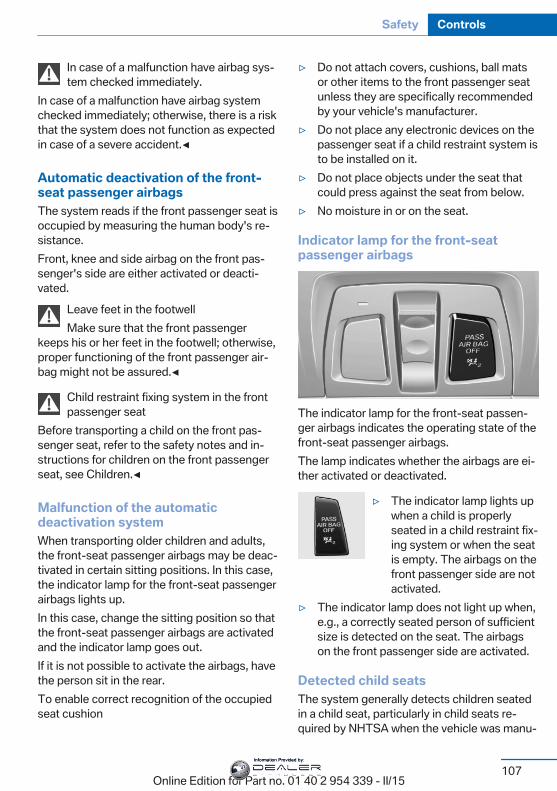
In case of a malfunction have airbag sys‐tem checked immediately.
In case of a malfunction have airbag systemchecked immediately; otherwise, there is a riskthat the system does not function as expectedin case of a severe accident.◀
Automatic deactivation of the front-seat passenger airbagsThe system reads if the front passenger seat isoccupied by measuring the human body's re‐sistance.Front, knee and side airbag on the front pas‐senger's side are either activated or deacti‐vated.
Leave feet in the footwellMake sure that the front passenger
keeps his or her feet in the footwell; otherwise,proper functioning of the front passenger air‐bag might not be assured.◀
Child restraint fixing system in the frontpassenger seat
Before transporting a child on the front pas‐senger seat, refer to the safety notes and in‐structions for children on the front passengerseat, see Children.◀
Malfunction of the automaticdeactivation systemWhen transporting older children and adults,the front-seat passenger airbags may be deac‐tivated in certain sitting positions. In this case,the indicator lamp for the front-seat passengerairbags lights up.In this case, change the sitting position so thatthe front-seat passenger airbags are activatedand the indicator lamp goes out.If it is not possible to activate the airbags, havethe person sit in the rear.To enable correct recognition of the occupiedseat cushion
▷ Do not attach covers, cushions, ball matsor other items to the front passenger seatunless they are specifically recommendedby your vehicle's manufacturer.
▷ Do not place any electronic devices on thepassenger seat if a child restraint system isto be installed on it.
▷ Do not place objects under the seat thatcould press against the seat from below.
▷ No moisture in or on the seat.
Indicator lamp for the front-seatpassenger airbags
The indicator lamp for the front-seat passen‐ger airbags indicates the operating state of thefront-seat passenger airbags.The lamp indicates whether the airbags are ei‐ther activated or deactivated.
▷ The indicator lamp lights upwhen a child is properlyseated in a child restraint fix‐ing system or when the seatis empty. The airbags on thefront passenger side are notactivated.
▷ The indicator lamp does not light up when,e.g., a correctly seated person of sufficientsize is detected on the seat. The airbagson the front passenger side are activated.
Detected child seatsThe system generally detects children seatedin a child seat, particularly in child seats re‐quired by NHTSA when the vehicle was manu‐
Seite 107
Safety Controls
107Online Edition for Part no. 01 40 2 954 339 - II/15
Information Provided by:
factured. After installing a child seat, makesure that the indicator lamp for the front-seatpassenger airbags lights up. This indicatesthat the child seat has been detected and thefront-seat passenger airbags are not activated.
Strength of the driver's and front-seatpassenger airbagThe explosive power that activates driver's/front passenger's airbags very much dependson the positions of the driver's/front passeng‐er's seat.With a respective message appearing on Con‐trol Display calibrate the front seats to keepthe accuracy of this function over the long-term.
Calibrating the front seatsA corresponding message appears on theControl Display.
1. Press the reel and move the respectiveseat all the way forward.
2. Press the reel forward again. The seat stillmoves forward slightly.
3. Readjust the seat to the desired position.The calibration procedure is completed whenthe message on the Control Display disap‐pears.If the message continues to be displayed, re‐peat the calibration.If the message does not disappear after a re‐peat calibration, have the system checked assoon as possible.
Unobstructed area of movementEnsure that the area of movement of the
seats is unobstructed to avoid personal injuryor damage to objects.◀
Tire Pressure Monitor TPMThe conceptThe system monitors tire inflation pressure inthe four mounted tires. The system warns youif there is a significant loss of pressure in oneor more tires. For this purpose, sensors in thetire valves measure the tire inflation pressureand tire temperature.
HintsTire damage due to external factorsSudden tire damage caused by external
circumstances cannot be recognized in ad‐vance.◀
With use of the system observe further infor‐mation found under Tire inflation pressure, re‐fer to page 186.
Functional requirementsThe system must have been reset with thecorrect tire inflation pressure; otherwise, relia‐ble signaling of tire inflation pressure loss isnot assured.Reset the system after each adjustment of thetire inflation pressure and after every tire orwheel change.Always use wheels with TPM electronics toensure that the system will operate properly.
Status displayThe current status of the Tire Pressure Moni‐tor TPM can be displayed on the Control Dis‐play, e.g., whether or not the TPM is active.On the Control Display:
1. "Vehicle info"2. "Vehicle status"3. "Tire Pressure Monitor (TPM)"The status is displayed.
Seite 108
Controls Safety
108Online Edition for Part no. 01 40 2 954 339 - II/15
Information Provided by:
Status control displayTire and system status are indicated by thecolor of the wheels and a text message on theControl Display.
All wheels greenSystem is active and will issue a warning rela‐tive to the tire inflation pressures stored duringthe last reset.
One wheel is yellowA flat tire or major drop in inflation pressure inthe indicated tire.
All wheels are yellowA flat tire or major drop in inflation pressure inseveral tires.
Wheels, grayThe system cannot detect a flat tire. Reasonsfor this may be:▷ The system is being reset.▷ Malfunction.
Status informationThe status control display additionally showsthe current tire inflation pressures and, de‐pending on the model, tire temperatures. Itshows the actual values read; they may varydepending on driving style or weather condi‐tions.
Carry out resetReset the system after each adjustment of thetire inflation pressure and after every tire orwheel change.On the Control Display and on the vehicle:
1. "Vehicle info"2. "Vehicle status"3. "Perform reset"4. Start the engine - do not drive off.
5. Reset tire inflation pressure:"Performreset".
6. Drive away.The tires are shown in gray and the status isdisplayed.After driving faster than 19 mph/30 km/h for ashort period, the set tire inflation pressures areaccepted as reference values. The reset iscompleted automatically while driving.After a successfully completed Reset, thewheels on the Control Display are shown ingreen and "Tire Pressure Monitor (TPM)active" is displayed.You may interrupt this trip at any time. Whenyou continue the reset resumes automatically.
Low tire pressure messageThe yellow warning lamp lights up. ACheck Control message is displayed.▷ There is a flat tire or a major loss in
tire inflation pressure.▷ No reset was performed for the system.
The system therefore issues a warningbased on the tire inflation pressures beforethe last reset.
1. Reduce your speed and stop cautiously.Avoid sudden braking and steering maneu‐vers.
2. Identify the damaged wheel. Do so bychecking the tire inflation pressure usingthe Mobility System. To correct the tire in‐flation pressure
3. Repair flat tire with the Mobility System orreplace the damaged wheel.
Required tire inflation pressure checkmessageA Check Control message is displayed in thefollowing situations▷ The system has detected a wheel change,
but no reset was done.
Seite 109
Safety Controls
109Online Edition for Part no. 01 40 2 954 339 - II/15
Information Provided by:
▷ Inflation was not carried out according tospecifications.
▷ The tire inflation pressure has fallen belowthe level of the last confirmation.
In this case:▷ Check the tire pressure and correct as
needed.▷ Carry out a reset of the system after a tire
change.
System limitsThe system does not function properly if a re‐set has not been carried out, e.g., a flat tire isreported though tire inflation pressures arecorrect.The tire inflation pressure depends on thetire's temperature. Driving or exposure to thesun will increase the tire's temperature, thusincreasing the tire inflation pressure. The tireinflation pressure is reduced when the tiretemperature falls again. These circumstancesmay cause a warning when temperatures fallvery sharply.
MalfunctionThe yellow warning lamp flashes andthen lights up continuously. A CheckControl message is displayed. No flat
tire or loss of tire inflation pressure can be de‐tected.
Display in the following situations:▷ A wheel without TPM electronics is fitted:
have the service center check it if needed.▷ Malfunction: have the system checked by
your service center.▷ TPM was unable to complete the reset.
Reset the system again.▷ Interference through systems or devices
with the same radio frequency: after leav‐ing the area of the interference, the systemautomatically becomes active again.
Declaration according to NHTSA/FMVSS 138 Tire Pressure MonitoringSystemEach tire, including the spare (if provided)should be checked monthly when cold and in‐flated to the inflation pressure recommendedby the vehicle manufacturer on the vehicleplacard or tire inflation pressure label. (If yourvehicle has tires of a different size than the sizeindicated on the vehicle placard or tire inflationpressure label, you should determine theproper tire inflation pressure for those tires.)As an added safety feature, your vehicle hasbeen equipped with a tire pressure monitoringsystem (TPMS) that illuminates a low tire pres‐sure telltale when one or more of your tires issignificantly under-inflated. Accordingly, whenthe low tire pressure telltale illuminates, youshould stop and check your tires as soon aspossible, and inflate them to the proper pres‐sure. Driving on a significantly under-inflatedtire causes the tire to overheat and can lead totire failure. Under-inflation also reduces fuel ef‐ficiency and tire tread life, and may affect thevehicle's handling and stopping ability. Pleasenote that the TPMS is not a substitute forproper tire maintenance, and it is the driver'sresponsibility to maintain correct tire pressure,even if under-inflation has not reached thelevel to trigger illumination of the TPMS lowtire pressure telltale. Your vehicle has alsobeen equipped with a TPMS malfunction indi‐cator to indicate when the system is not oper‐ating properly. The TPMS malfunction indica‐tor is combined with the low tire pressuretelltale. When the system detects a malfunc‐tion, the telltale will flash for approximately oneminute and then remain continuously illumi‐nated. This sequence will continue upon sub‐sequent vehicle start-ups as long as the mal‐function exists. When the malfunction indicatoris illuminated, the system may not be able todetect or signal low tire pressure as intended.TPMS malfunctions may occur for a variety ofreasons, including the installation of replace‐ment or alternate tires or wheels on the vehicle
Seite 110
Controls Safety
110Online Edition for Part no. 01 40 2 954 339 - II/15
Information Provided by:
that prevent the TPMS from functioning prop‐erly. Always check the TPMS malfunction tell‐tale after replacing one or more tires or wheelson your vehicle to ensure that the replacementor alternate tires and wheels allow the TPMSto continue to function properly.
FTM Flat Tire MonitorThe conceptThe system detects tire inflation pressure losson the basis of rotation speed differences be‐tween the individual wheels while driving.In the event of a tire inflation pressure loss, thediameter and therefore the rotational speed ofthe corresponding wheel changes. This will bedetected and reported as a flat tire.The system does not measure the actual infla‐tion pressure in the tires.
Functional requirementsThe system must have been initialized whenthe tire inflation pressure was correct; other‐wise, reliable flagging of a flat tire is not as‐sured. Initialize the system after each correc‐tion of the tire inflation pressure and afterevery tire or wheel change.
Status displayThe current status of the Flat Tire Monitor canbe displayed on the Control Display, e.g.,whether or not the FTM is active.On the Control Display:
1. "Vehicle info"2. "Vehicle status"3. "Flat Tire Monitor (FTM)"The status is displayed.
InitializationWhen initializing the once set inflation tirepressures serve as reference values in order to
detect a flat tire. Initialization is started by con‐firming the tire inflation pressures.Do not initialize the system when driving withsnow chains.On the Control Display:
1. "Vehicle info"2. "Vehicle status"3. "Perform reset"4. Start the engine - do not drive off.5. Start the initialization with "Perform reset".6. Drive away.The initialization is completed while driving,which can be interrupted at any time.The initialization automatically continues whendriving resumes.
Indication of a flat tireThe yellow warning lamp lights up. ACheck Control message is displayed.There is a flat tire or a major loss in tire
inflation pressure.
1. Reduce your speed and stop cautiously.Avoid sudden braking and steering maneu‐vers.
2. Identify the damaged wheel. Do so bychecking the tire inflation pressure usingthe Mobility System. If the tire inflationpressure in all tires is correct, the Flat TireMonitor may not have been initialized. Inthis case, initialize the system.
3. Repair flat tire with the Mobility System orreplace the damaged wheel.
System limitsSudden tire damageSudden serious tire damage caused by
external circumstances cannot be recognizedin advance.◀
Seite 111
Safety Controls
111Online Edition for Part no. 01 40 2 954 339 - II/15
Information Provided by:
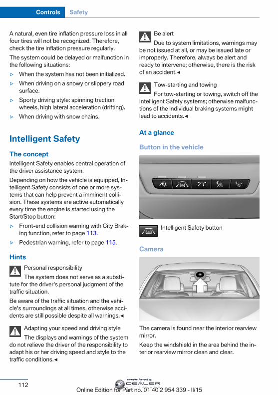
A natural, even tire inflation pressure loss in allfour tires will not be recognized. Therefore,check the tire inflation pressure regularly.The system could be delayed or malfunction inthe following situations:▷ When the system has not been initialized.▷ When driving on a snowy or slippery road
surface.▷ Sporty driving style: spinning traction
wheels, high lateral acceleration (drifting).▷ When driving with snow chains.
Intelligent SafetyThe conceptIntelligent Safety enables central operation ofthe driver assistance system.Depending on how the vehicle is equipped, In‐telligent Safety consists of one or more sys‐tems that can help prevent a imminent colli‐sion. These systems are active automaticallyevery time the engine is started using theStart/Stop button:▷ Front-end collision warning with City Brak‐
ing function, refer to page 113.▷ Pedestrian warning, refer to page 115.
HintsPersonal responsibilityThe system does not serve as a substi‐
tute for the driver's personal judgment of thetraffic situation.Be aware of the traffic situation and the vehi‐cle's surroundings at all times, otherwise acci‐dents are still possible despite all warnings.◀
Adapting your speed and driving styleThe displays and warnings of the system
do not relieve the driver of the responsibility toadapt his or her driving speed and style to thetraffic conditions.◀
Be alertDue to system limitations, warnings may
be not issued at all, or may be issued late orimproperly. Therefore, always be alert andready to intervene; otherwise, there is the riskof an accident.◀
Tow-starting and towingFor tow-starting or towing, switch off the
Intelligent Safety systems; otherwise malfunc‐tions of the individual braking systems mightlead to accidents.◀
At a glance
Button in the vehicle
Intelligent Safety button
Camera
The camera is found near the interior rearviewmirror.Keep the windshield in the area behind the in‐terior rearview mirror clean and clear.
Seite 112
Controls Safety
112Online Edition for Part no. 01 40 2 954 339 - II/15
Information Provided by:
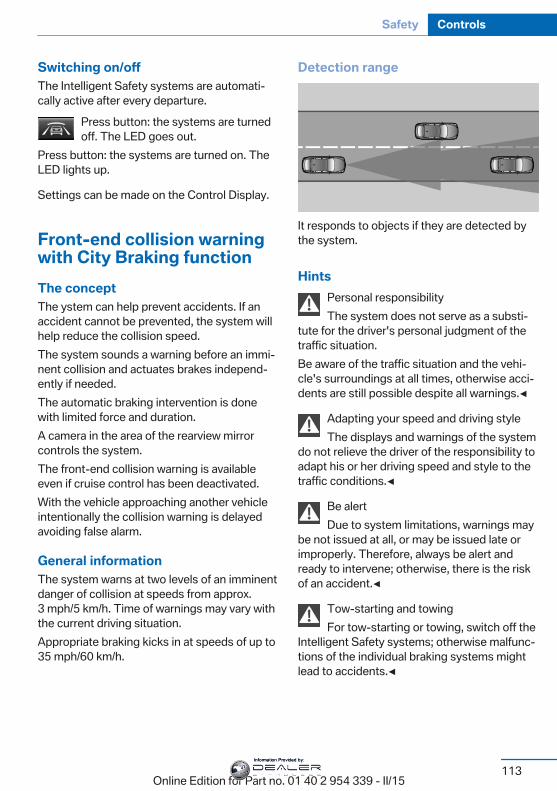
Switching on/offThe Intelligent Safety systems are automati‐cally active after every departure.
Press button: the systems are turnedoff. The LED goes out.
Press button: the systems are turned on. TheLED lights up.
Settings can be made on the Control Display.
Front-end collision warningwith City Braking functionThe conceptThe ystem can help prevent accidents. If anaccident cannot be prevented, the system willhelp reduce the collision speed.The system sounds a warning before an immi‐nent collision and actuates brakes independ‐ently if needed.The automatic braking intervention is donewith limited force and duration.A camera in the area of the rearview mirrorcontrols the system.The front-end collision warning is availableeven if cruise control has been deactivated.With the vehicle approaching another vehicleintentionally the collision warning is delayedavoiding false alarm.
General informationThe system warns at two levels of an imminentdanger of collision at speeds from approx.3 mph/5 km/h. Time of warnings may vary withthe current driving situation.Appropriate braking kicks in at speeds of up to35 mph/60 km/h.
Detection range
It responds to objects if they are detected bythe system.
HintsPersonal responsibilityThe system does not serve as a substi‐
tute for the driver's personal judgment of thetraffic situation.Be aware of the traffic situation and the vehi‐cle's surroundings at all times, otherwise acci‐dents are still possible despite all warnings.◀
Adapting your speed and driving styleThe displays and warnings of the system
do not relieve the driver of the responsibility toadapt his or her driving speed and style to thetraffic conditions.◀
Be alertDue to system limitations, warnings may
be not issued at all, or may be issued late orimproperly. Therefore, always be alert andready to intervene; otherwise, there is the riskof an accident.◀
Tow-starting and towingFor tow-starting or towing, switch off the
Intelligent Safety systems; otherwise malfunc‐tions of the individual braking systems mightlead to accidents.◀
Seite 113
Safety Controls
113Online Edition for Part no. 01 40 2 954 339 - II/15
Information Provided by:
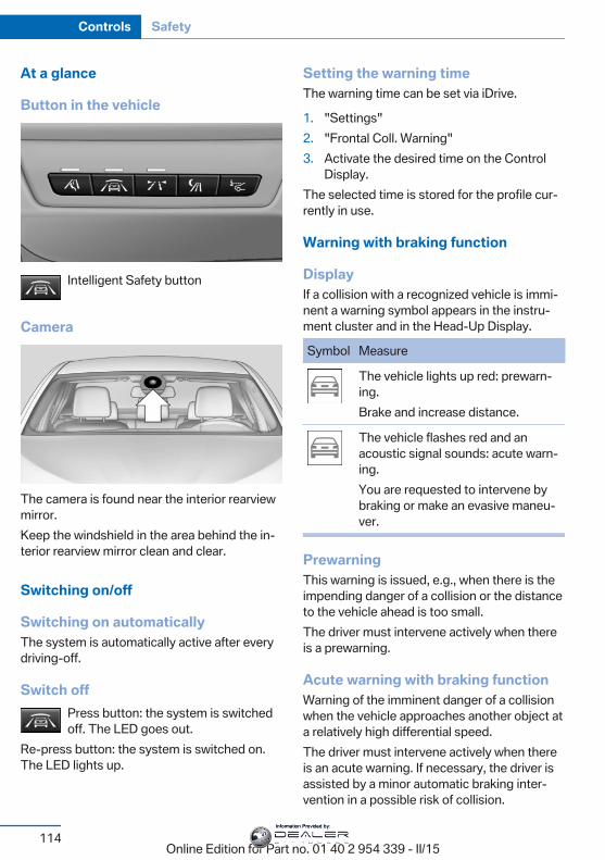
At a glance
Button in the vehicle
Intelligent Safety button
Camera
The camera is found near the interior rearviewmirror.Keep the windshield in the area behind the in‐terior rearview mirror clean and clear.
Switching on/off
Switching on automaticallyThe system is automatically active after everydriving-off.
Switch offPress button: the system is switchedoff. The LED goes out.
Re-press button: the system is switched on.The LED lights up.
Setting the warning timeThe warning time can be set via iDrive.
1. "Settings"2. "Frontal Coll. Warning"3. Activate the desired time on the Control
Display.The selected time is stored for the profile cur‐rently in use.
Warning with braking function
DisplayIf a collision with a recognized vehicle is immi‐nent a warning symbol appears in the instru‐ment cluster and in the Head-Up Display.
Symbol Measure
The vehicle lights up red: prewarn‐ing.Brake and increase distance.
The vehicle flashes red and anacoustic signal sounds: acute warn‐ing.You are requested to intervene bybraking or make an evasive maneu‐ver.
PrewarningThis warning is issued, e.g., when there is theimpending danger of a collision or the distanceto the vehicle ahead is too small.The driver must intervene actively when thereis a prewarning.
Acute warning with braking functionWarning of the imminent danger of a collisionwhen the vehicle approaches another object ata relatively high differential speed.The driver must intervene actively when thereis an acute warning. If necessary, the driver isassisted by a minor automatic braking inter‐vention in a possible risk of collision.
Seite 114
Controls Safety
114Online Edition for Part no. 01 40 2 954 339 - II/15
Information Provided by:
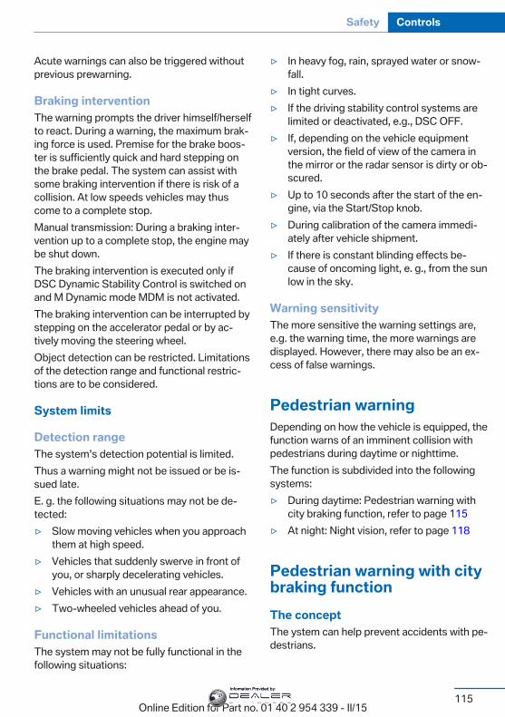
Acute warnings can also be triggered withoutprevious prewarning.
Braking interventionThe warning prompts the driver himself/herselfto react. During a warning, the maximum brak‐ing force is used. Premise for the brake boos‐ter is sufficiently quick and hard stepping onthe brake pedal. The system can assist withsome braking intervention if there is risk of acollision. At low speeds vehicles may thuscome to a complete stop.Manual transmission: During a braking inter‐vention up to a complete stop, the engine maybe shut down.The braking intervention is executed only ifDSC Dynamic Stability Control is switched onand M Dynamic mode MDM is not activated.The braking intervention can be interrupted bystepping on the accelerator pedal or by ac‐tively moving the steering wheel.Object detection can be restricted. Limitationsof the detection range and functional restric‐tions are to be considered.
System limits
Detection rangeThe system's detection potential is limited.Thus a warning might not be issued or be is‐sued late.E. g. the following situations may not be de‐tected:▷ Slow moving vehicles when you approach
them at high speed.▷ Vehicles that suddenly swerve in front of
you, or sharply decelerating vehicles.▷ Vehicles with an unusual rear appearance.▷ Two-wheeled vehicles ahead of you.
Functional limitationsThe system may not be fully functional in thefollowing situations:
▷ In heavy fog, rain, sprayed water or snow‐fall.
▷ In tight curves.▷ If the driving stability control systems are
limited or deactivated, e.g., DSC OFF.▷ If, depending on the vehicle equipment
version, the field of view of the camera inthe mirror or the radar sensor is dirty or ob‐scured.
▷ Up to 10 seconds after the start of the en‐gine, via the Start/Stop knob.
▷ During calibration of the camera immedi‐ately after vehicle shipment.
▷ If there is constant blinding effects be‐cause of oncoming light, e. g., from the sunlow in the sky.
Warning sensitivityThe more sensitive the warning settings are,e.g. the warning time, the more warnings aredisplayed. However, there may also be an ex‐cess of false warnings.
Pedestrian warningDepending on how the vehicle is equipped, thefunction warns of an imminent collision withpedestrians during daytime or nighttime.The function is subdivided into the followingsystems:▷ During daytime: Pedestrian warning with
city braking function, refer to page 115▷ At night: Night vision, refer to page 118
Pedestrian warning with citybraking functionThe conceptThe ystem can help prevent accidents with pe‐destrians.
Seite 115
Safety Controls
115Online Edition for Part no. 01 40 2 954 339 - II/15
Information Provided by:
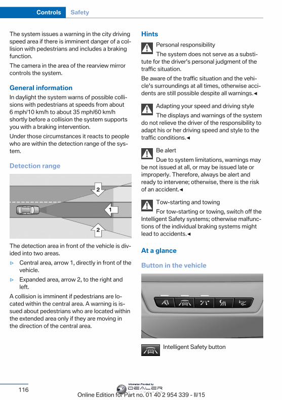
The system issues a warning in the city drivingspeed area if there is imminent danger of a col‐lision with pedestrians and includes a brakingfunction.The camera in the area of the rearview mirrorcontrols the system.
General informationIn daylight the system warns of possible colli‐sions with pedestrians at speeds from about6 mph/10 km/h to about 35 mph/60 km/hshortly before a collision the system supportsyou with a braking intervention.Under those circumstances it reacts to peoplewho are within the detection range of the sys‐tem.
Detection range
The detection area in front of the vehicle is div‐ided into two areas.▷ Central area, arrow 1, directly in front of the
vehicle.▷ Expanded area, arrow 2, to the right and
left.A collision is imminent if pedestrians are lo‐cated within the central area. A warning is is‐sued about pedestrians who are located withinthe extended area only if they are moving inthe direction of the central area.
HintsPersonal responsibilityThe system does not serve as a substi‐
tute for the driver's personal judgment of thetraffic situation.Be aware of the traffic situation and the vehi‐cle's surroundings at all times, otherwise acci‐dents are still possible despite all warnings.◀
Adapting your speed and driving styleThe displays and warnings of the system
do not relieve the driver of the responsibility toadapt his or her driving speed and style to thetraffic conditions.◀
Be alertDue to system limitations, warnings may
be not issued at all, or may be issued late orimproperly. Therefore, always be alert andready to intervene; otherwise, there is the riskof an accident.◀
Tow-starting and towingFor tow-starting or towing, switch off the
Intelligent Safety systems; otherwise malfunc‐tions of the individual braking systems mightlead to accidents.◀
At a glance
Button in the vehicle
Intelligent Safety button
Seite 116
Controls Safety
116Online Edition for Part no. 01 40 2 954 339 - II/15
Information Provided by:
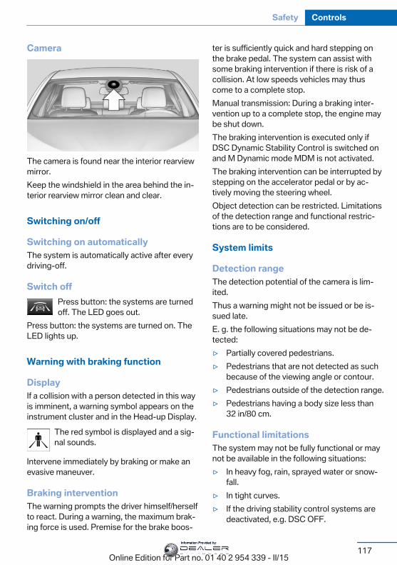
Camera
The camera is found near the interior rearviewmirror.Keep the windshield in the area behind the in‐terior rearview mirror clean and clear.
Switching on/off
Switching on automaticallyThe system is automatically active after everydriving-off.
Switch offPress button: the systems are turnedoff. The LED goes out.
Press button: the systems are turned on. TheLED lights up.
Warning with braking function
DisplayIf a collision with a person detected in this wayis imminent, a warning symbol appears on theinstrument cluster and in the Head-up Display.
The red symbol is displayed and a sig‐nal sounds.
Intervene immediately by braking or make anevasive maneuver.
Braking interventionThe warning prompts the driver himself/herselfto react. During a warning, the maximum brak‐ing force is used. Premise for the brake boos‐
ter is sufficiently quick and hard stepping onthe brake pedal. The system can assist withsome braking intervention if there is risk of acollision. At low speeds vehicles may thuscome to a complete stop.Manual transmission: During a braking inter‐vention up to a complete stop, the engine maybe shut down.The braking intervention is executed only ifDSC Dynamic Stability Control is switched onand M Dynamic mode MDM is not activated.The braking intervention can be interrupted bystepping on the accelerator pedal or by ac‐tively moving the steering wheel.Object detection can be restricted. Limitationsof the detection range and functional restric‐tions are to be considered.
System limits
Detection rangeThe detection potential of the camera is lim‐ited.Thus a warning might not be issued or be is‐sued late.E. g. the following situations may not be de‐tected:▷ Partially covered pedestrians.▷ Pedestrians that are not detected as such
because of the viewing angle or contour.▷ Pedestrians outside of the detection range.▷ Pedestrians having a body size less than
32 in/80 cm.
Functional limitationsThe system may not be fully functional or maynot be available in the following situations:▷ In heavy fog, rain, sprayed water or snow‐
fall.▷ In tight curves.▷ If the driving stability control systems are
deactivated, e.g. DSC OFF.
Seite 117
Safety Controls
117Online Edition for Part no. 01 40 2 954 339 - II/15
Information Provided by:
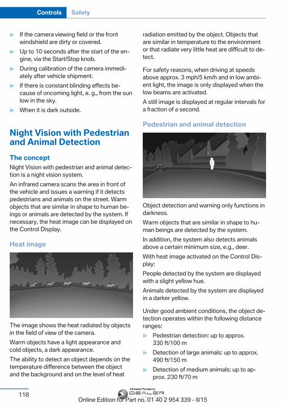
▷ If the camera viewing field or the frontwindshield are dirty or covered.
▷ Up to 10 seconds after the start of the en‐gine, via the Start/Stop knob.
▷ During calibration of the camera immedi‐ately after vehicle shipment.
▷ If there is constant blinding effects be‐cause of oncoming light, e. g., from the sunlow in the sky.
▷ When it is dark outside.
Night Vision with Pedestrianand Animal DetectionThe conceptNight Vision with pedestrian and animal detec‐tion is a night vision system.An infrared camera scans the area in front ofthe vehicle and issues a warning if it detectspedestrians and animals on the street. Warmobjects that are similar in shape to human be‐ings or animals are detected by the system. Ifnecessary, the heat image can be displayed onthe Control Display.
Heat image
The image shows the heat radiated by objectsin the field of view of the camera.Warm objects have a light appearance andcold objects, a dark appearance.The ability to detect an object depends on thetemperature difference between the objectand the background and on the level of heat
radiation emitted by the object. Objects thatare similar in temperature to the environmentor that radiate very little heat are difficult to de‐tect.
For safety reasons, when driving at speedsabove approx. 3 mph/5 km/h and in low ambi‐ent light, the image is only displayed when thelow beams are activated.A still image is displayed at regular intervals fora fraction of a second.
Pedestrian and animal detection
Object detection and warning only functions indarkness.Warm objects that are similar in shape to hu‐man beings are detected by the system.In addition, the system also detects animalsabove a certain minimum size, e.g., deer.With heat image activated on the Control Dis‐play:People detected by the system are displayedwith a slight yellow hue.Animals detected by the system are displayedin a darker yellow.
Under good ambient conditions, the object de‐tection operates within the following distanceranges:▷ Pedestrian detection: up to approx.
330 ft/100 m▷ Detection of large animals: up to approx.
490 ft/150 m▷ Detection of medium animals: up to ap‐
prox. 230 ft/70 m
Seite 118
Controls Safety
118Online Edition for Part no. 01 40 2 954 339 - II/15
Information Provided by:
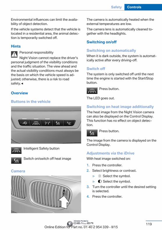
Environmental influences can limit the availa‐bility of object detection.If the vehicle systems detect that the vehicle islocated in a residential area, the animal detec‐tion is temporarily switched off.
HintsPersonal responsibilityNight Vision cannot replace the driver's
personal judgment of the visibility conditionsand the traffic situation. The view ahead andthe actual visibility conditions must always bethe basis on which the vehicle speed is ad‐justed; otherwise, there is a risk to roadsafety.◀
Overview
Buttons in the vehicle
Intelligent Safety button
Switch on/switch off heat image
Camera
The camera is automatically heated when theexternal temperatures are low.The camera lens is automatically cleaned to‐gether with the headlights.
Switching on/off
Switching on automaticallyWhen it is dark outside, the system is automat‐ically active after every driving-off.
Switch offThe system is only switched off until the nexttime the engine is started with the Start/Stopbutton.
Press button.
The LED goes out.
Switching on heat image additionallyThe heat image from the Night Vision cameracan also be displayed on the Control Display.This function has no effect on object detec‐tion.
Press button.
The image from the camera is displayed on theControl Display.
Adjustments via the iDriveWith heat image switched on:
1. Press the controller.2. Select brightness or contrast.
▷ Select the symbol.▷ Select the symbol.
3. Turn the controller until the desired settingis selected.
4. Press the controller.
Seite 119
Safety Controls
119Online Edition for Part no. 01 40 2 954 339 - II/15
Information Provided by:
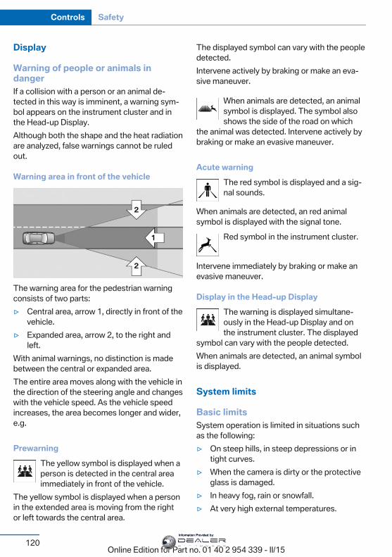
Display
Warning of people or animals indangerIf a collision with a person or an animal de‐tected in this way is imminent, a warning sym‐bol appears on the instrument cluster and inthe Head-up Display.Although both the shape and the heat radiationare analyzed, false warnings cannot be ruledout.
Warning area in front of the vehicle
The warning area for the pedestrian warningconsists of two parts:▷ Central area, arrow 1, directly in front of the
vehicle.▷ Expanded area, arrow 2, to the right and
left.With animal warnings, no distinction is madebetween the central or expanded area.The entire area moves along with the vehicle inthe direction of the steering angle and changeswith the vehicle speed. As the vehicle speedincreases, the area becomes longer and wider,e.g.
PrewarningThe yellow symbol is displayed when aperson is detected in the central areaimmediately in front of the vehicle.
The yellow symbol is displayed when a personin the extended area is moving from the rightor left towards the central area.
The displayed symbol can vary with the peopledetected.Intervene actively by braking or make an eva‐sive maneuver.
When animals are detected, an animalsymbol is displayed. The symbol alsoshows the side of the road on which
the animal was detected. Intervene actively bybraking or make an evasive maneuver.
Acute warningThe red symbol is displayed and a sig‐nal sounds.
When animals are detected, an red animalsymbol is displayed with the signal tone.
Red symbol in the instrument cluster.
Intervene immediately by braking or make anevasive maneuver.
Display in the Head-up DisplayThe warning is displayed simultane‐ously in the Head-up Display and onthe instrument cluster. The displayed
symbol can vary with the people detected.When animals are detected, an animal symbolis displayed.
System limits
Basic limitsSystem operation is limited in situations suchas the following:▷ On steep hills, in steep depressions or in
tight curves.▷ When the camera is dirty or the protective
glass is damaged.▷ In heavy fog, rain or snowfall.▷ At very high external temperatures.
Seite 120
Controls Safety
120Online Edition for Part no. 01 40 2 954 339 - II/15
Information Provided by:
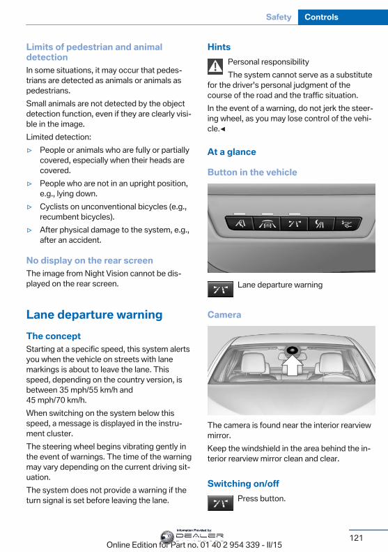
Limits of pedestrian and animaldetectionIn some situations, it may occur that pedes‐trians are detected as animals or animals aspedestrians.Small animals are not detected by the objectdetection function, even if they are clearly visi‐ble in the image.Limited detection:▷ People or animals who are fully or partially
covered, especially when their heads arecovered.
▷ People who are not in an upright position,e.g., lying down.
▷ Cyclists on unconventional bicycles (e.g.,recumbent bicycles).
▷ After physical damage to the system, e.g.,after an accident.
No display on the rear screenThe image from Night Vision cannot be dis‐played on the rear screen.
Lane departure warningThe conceptStarting at a specific speed, this system alertsyou when the vehicle on streets with lanemarkings is about to leave the lane. Thisspeed, depending on the country version, isbetween 35 mph/55 km/h and45 mph/70 km/h.When switching on the system below thisspeed, a message is displayed in the instru‐ment cluster.The steering wheel begins vibrating gently inthe event of warnings. The time of the warningmay vary depending on the current driving sit‐uation.The system does not provide a warning if theturn signal is set before leaving the lane.
HintsPersonal responsibilityThe system cannot serve as a substitute
for the driver's personal judgment of thecourse of the road and the traffic situation.In the event of a warning, do not jerk the steer‐ing wheel, as you may lose control of the vehi‐cle.◀
At a glance
Button in the vehicle
Lane departure warning
Camera
The camera is found near the interior rearviewmirror.Keep the windshield in the area behind the in‐terior rearview mirror clean and clear.
Switching on/offPress button.
Seite 121
Safety Controls
121Online Edition for Part no. 01 40 2 954 339 - II/15
Information Provided by:
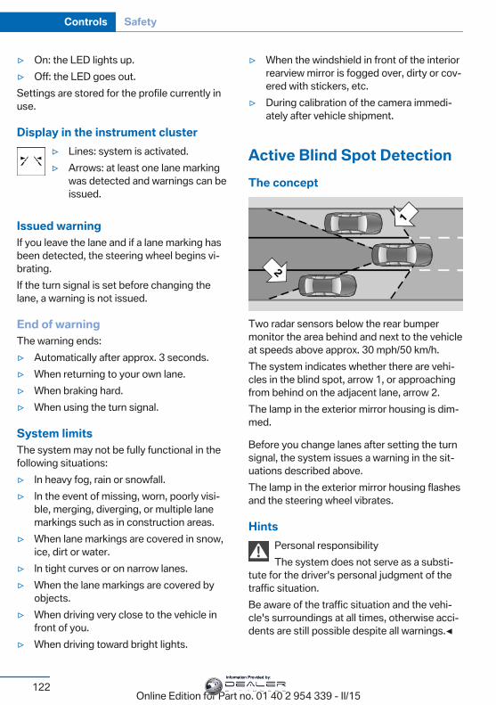
▷ On: the LED lights up.▷ Off: the LED goes out.Settings are stored for the profile currently inuse.
Display in the instrument cluster▷ Lines: system is activated.▷ Arrows: at least one lane marking
was detected and warnings can beissued.
Issued warningIf you leave the lane and if a lane marking hasbeen detected, the steering wheel begins vi‐brating.If the turn signal is set before changing thelane, a warning is not issued.
End of warningThe warning ends:▷ Automatically after approx. 3 seconds.▷ When returning to your own lane.▷ When braking hard.▷ When using the turn signal.
System limitsThe system may not be fully functional in thefollowing situations:▷ In heavy fog, rain or snowfall.▷ In the event of missing, worn, poorly visi‐
ble, merging, diverging, or multiple lanemarkings such as in construction areas.
▷ When lane markings are covered in snow,ice, dirt or water.
▷ In tight curves or on narrow lanes.▷ When the lane markings are covered by
objects.▷ When driving very close to the vehicle in
front of you.▷ When driving toward bright lights.
▷ When the windshield in front of the interiorrearview mirror is fogged over, dirty or cov‐ered with stickers, etc.
▷ During calibration of the camera immedi‐ately after vehicle shipment.
Active Blind Spot DetectionThe concept
Two radar sensors below the rear bumpermonitor the area behind and next to the vehicleat speeds above approx. 30 mph/50 km/h.The system indicates whether there are vehi‐cles in the blind spot, arrow 1, or approachingfrom behind on the adjacent lane, arrow 2.The lamp in the exterior mirror housing is dim‐med.
Before you change lanes after setting the turnsignal, the system issues a warning in the sit‐uations described above.The lamp in the exterior mirror housing flashesand the steering wheel vibrates.
HintsPersonal responsibilityThe system does not serve as a substi‐
tute for the driver's personal judgment of thetraffic situation.Be aware of the traffic situation and the vehi‐cle's surroundings at all times, otherwise acci‐dents are still possible despite all warnings.◀
Seite 122
Controls Safety
122Online Edition for Part no. 01 40 2 954 339 - II/15
Information Provided by:
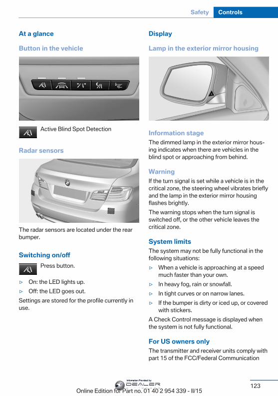
At a glance
Button in the vehicle
Active Blind Spot Detection
Radar sensors
The radar sensors are located under the rearbumper.
Switching on/offPress button.
▷ On: the LED lights up.▷ Off: the LED goes out.Settings are stored for the profile currently inuse.
Display
Lamp in the exterior mirror housing
Information stageThe dimmed lamp in the exterior mirror hous‐ing indicates when there are vehicles in theblind spot or approaching from behind.
WarningIf the turn signal is set while a vehicle is in thecritical zone, the steering wheel vibrates brieflyand the lamp in the exterior mirror housingflashes brightly.The warning stops when the turn signal isswitched off, or the other vehicle leaves thecritical zone.
System limitsThe system may not be fully functional in thefollowing situations:▷ When a vehicle is approaching at a speed
much faster than your own.▷ In heavy fog, rain or snowfall.▷ In tight curves or on narrow lanes.▷ If the bumper is dirty or iced up, or covered
with stickers.A Check Control message is displayed whenthe system is not fully functional.
For US owners onlyThe transmitter and receiver units comply withpart 15 of the FCC/Federal Communication
Seite 123
Safety Controls
123Online Edition for Part no. 01 40 2 954 339 - II/15
Information Provided by:
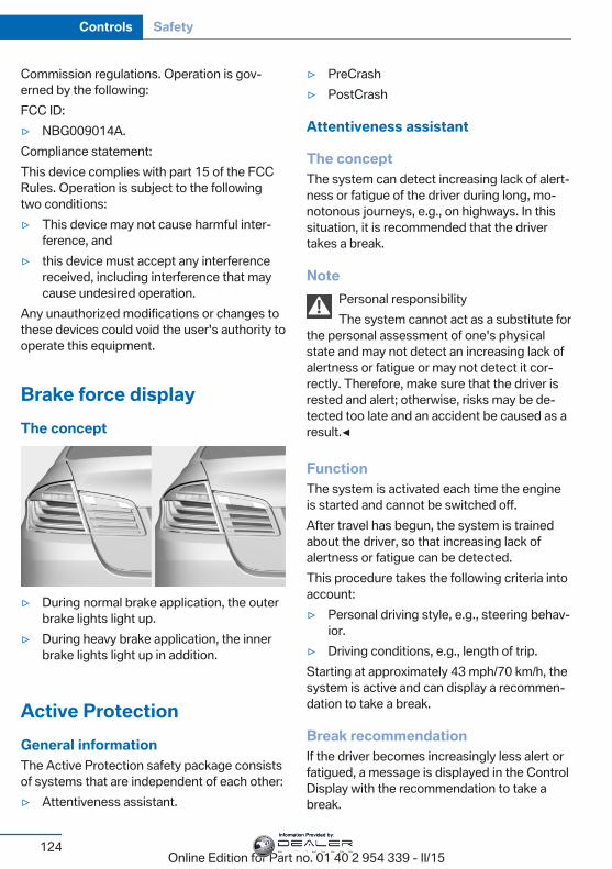
Commission regulations. Operation is gov‐erned by the following:FCC ID:▷ NBG009014A.Compliance statement:This device complies with part 15 of the FCCRules. Operation is subject to the followingtwo conditions:▷ This device may not cause harmful inter‐
ference, and▷ this device must accept any interference
received, including interference that maycause undesired operation.
Any unauthorized modifications or changes tothese devices could void the user's authority tooperate this equipment.
Brake force displayThe concept
▷ During normal brake application, the outerbrake lights light up.
▷ During heavy brake application, the innerbrake lights light up in addition.
Active ProtectionGeneral informationThe Active Protection safety package consistsof systems that are independent of each other:▷ Attentiveness assistant.
▷ PreCrash▷ PostCrash
Attentiveness assistant
The conceptThe system can detect increasing lack of alert‐ness or fatigue of the driver during long, mo‐notonous journeys, e.g., on highways. In thissituation, it is recommended that the drivertakes a break.
NotePersonal responsibilityThe system cannot act as a substitute for
the personal assessment of one's physicalstate and may not detect an increasing lack ofalertness or fatigue or may not detect it cor‐rectly. Therefore, make sure that the driver isrested and alert; otherwise, risks may be de‐tected too late and an accident be caused as aresult.◀
FunctionThe system is activated each time the engineis started and cannot be switched off.After travel has begun, the system is trainedabout the driver, so that increasing lack ofalertness or fatigue can be detected.This procedure takes the following criteria intoaccount:▷ Personal driving style, e.g., steering behav‐
ior.▷ Driving conditions, e.g., length of trip.Starting at approximately 43 mph/70 km/h, thesystem is active and can display a recommen‐dation to take a break.
Break recommendationIf the driver becomes increasingly less alert orfatigued, a message is displayed in the ControlDisplay with the recommendation to take abreak.
Seite 124
Controls Safety
124Online Edition for Part no. 01 40 2 954 339 - II/15
Information Provided by:
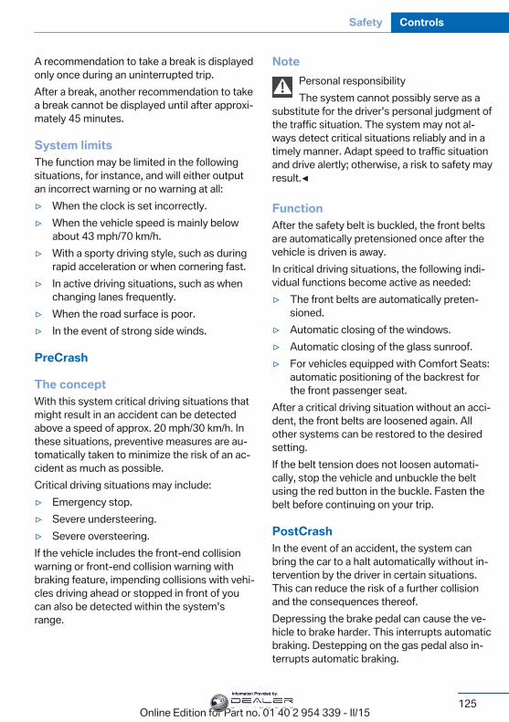
A recommendation to take a break is displayedonly once during an uninterrupted trip.After a break, another recommendation to takea break cannot be displayed until after approxi‐mately 45 minutes.
System limitsThe function may be limited in the followingsituations, for instance, and will either outputan incorrect warning or no warning at all:▷ When the clock is set incorrectly.▷ When the vehicle speed is mainly below
about 43 mph/70 km/h.▷ With a sporty driving style, such as during
rapid acceleration or when cornering fast.▷ In active driving situations, such as when
changing lanes frequently.▷ When the road surface is poor.▷ In the event of strong side winds.
PreCrash
The conceptWith this system critical driving situations thatmight result in an accident can be detectedabove a speed of approx. 20 mph/30 km/h. Inthese situations, preventive measures are au‐tomatically taken to minimize the risk of an ac‐cident as much as possible.Critical driving situations may include:▷ Emergency stop.▷ Severe understeering.▷ Severe oversteering.If the vehicle includes the front-end collisionwarning or front-end collision warning withbraking feature, impending collisions with vehi‐cles driving ahead or stopped in front of youcan also be detected within the system'srange.
NotePersonal responsibilityThe system cannot possibly serve as a
substitute for the driver's personal judgment ofthe traffic situation. The system may not al‐ways detect critical situations reliably and in atimely manner. Adapt speed to traffic situationand drive alertly; otherwise, a risk to safety mayresult.◀
FunctionAfter the safety belt is buckled, the front beltsare automatically pretensioned once after thevehicle is driven is away.In critical driving situations, the following indi‐vidual functions become active as needed:▷ The front belts are automatically preten‐
sioned.▷ Automatic closing of the windows.▷ Automatic closing of the glass sunroof.▷ For vehicles equipped with Comfort Seats:
automatic positioning of the backrest forthe front passenger seat.
After a critical driving situation without an acci‐dent, the front belts are loosened again. Allother systems can be restored to the desiredsetting.If the belt tension does not loosen automati‐cally, stop the vehicle and unbuckle the beltusing the red button in the buckle. Fasten thebelt before continuing on your trip.
PostCrashIn the event of an accident, the system canbring the car to a halt automatically without in‐tervention by the driver in certain situations.This can reduce the risk of a further collisionand the consequences thereof.Depressing the brake pedal can cause the ve‐hicle to brake harder. This interrupts automaticbraking. Destepping on the gas pedal also in‐terrupts automatic braking.
Seite 125
Safety Controls
125Online Edition for Part no. 01 40 2 954 339 - II/15
Information Provided by:
After coming to a halt, the brake is releasedautomatically. Secure the vehicle against roll‐ing.
Seite 126
Controls Safety
126Online Edition for Part no. 01 40 2 954 339 - II/15
Information Provided by:
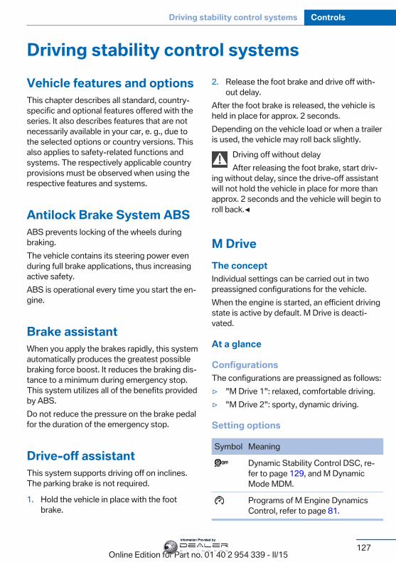
Driving stability control systemsVehicle features and optionsThis chapter describes all standard, country-specific and optional features offered with theseries. It also describes features that are notnecessarily available in your car, e. g., due tothe selected options or country versions. Thisalso applies to safety-related functions andsystems. The respectively applicable countryprovisions must be observed when using therespective features and systems.
Antilock Brake System ABSABS prevents locking of the wheels duringbraking.The vehicle contains its steering power evenduring full brake applications, thus increasingactive safety.ABS is operational every time you start the en‐gine.
Brake assistantWhen you apply the brakes rapidly, this systemautomatically produces the greatest possiblebraking force boost. It reduces the braking dis‐tance to a minimum during emergency stop.This system utilizes all of the benefits providedby ABS.Do not reduce the pressure on the brake pedalfor the duration of the emergency stop.
Drive-off assistantThis system supports driving off on inclines.The parking brake is not required.
1. Hold the vehicle in place with the footbrake.
2. Release the foot brake and drive off with‐out delay.
After the foot brake is released, the vehicle isheld in place for approx. 2 seconds.Depending on the vehicle load or when a traileris used, the vehicle may roll back slightly.
Driving off without delayAfter releasing the foot brake, start driv‐
ing without delay, since the drive-off assistantwill not hold the vehicle in place for more thanapprox. 2 seconds and the vehicle will begin toroll back.◀
M DriveThe conceptIndividual settings can be carried out in twopreassigned configurations for the vehicle.When the engine is started, an efficient drivingstate is active by default. M Drive is deacti‐vated.
At a glance
ConfigurationsThe configurations are preassigned as follows:▷ "M Drive 1": relaxed, comfortable driving.▷ "M Drive 2": sporty, dynamic driving.
Setting options
Symbol Meaning
Dynamic Stability Control DSC, re‐fer to page 129, and M DynamicMode MDM.
Programs of M Engine DynamicsControl, refer to page 81.
Seite 127
Driving stability control systems Controls
127Online Edition for Part no. 01 40 2 954 339 - II/15
Information Provided by:
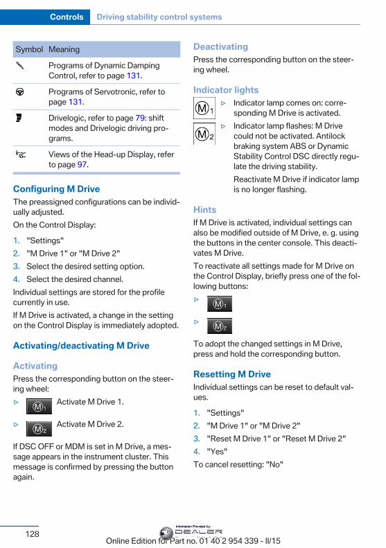
Symbol Meaning
Programs of Dynamic DampingControl, refer to page 131.
Programs of Servotronic, refer topage 131.
Drivelogic, refer to page 79: shiftmodes and Drivelogic driving pro‐grams.
Views of the Head-up Display, referto page 97.
Configuring M DriveThe preassigned configurations can be individ‐ually adjusted.On the Control Display:
1. "Settings"2. "M Drive 1" or "M Drive 2"3. Select the desired setting option.4. Select the desired channel.Individual settings are stored for the profilecurrently in use.If M Drive is activated, a change in the settingon the Control Display is immediately adopted.
Activating/deactivating M Drive
ActivatingPress the corresponding button on the steer‐ing wheel:▷ Activate M Drive 1.
▷ Activate M Drive 2.
If DSC OFF or MDM is set in M Drive, a mes‐sage appears in the instrument cluster. Thismessage is confirmed by pressing the buttonagain.
DeactivatingPress the corresponding button on the steer‐ing wheel.
Indicator lights▷ Indicator lamp comes on: corre‐
sponding M Drive is activated.▷ Indicator lamp flashes: M Drive
could not be activated. Antilockbraking system ABS or DynamicStability Control DSC directly regu‐late the driving stability.Reactivate M Drive if indicator lampis no longer flashing.
HintsIf M Drive is activated, individual settings canalso be modified outside of M Drive, e. g. usingthe buttons in the center console. This deacti‐vates M Drive.To reactivate all settings made for M Drive onthe Control Display, briefly press one of the fol‐lowing buttons:▷
▷
To adopt the changed settings in M Drive,press and hold the corresponding button.
Resetting M DriveIndividual settings can be reset to default val‐ues.
1. "Settings"2. "M Drive 1" or "M Drive 2"3. "Reset M Drive 1" or "Reset M Drive 2"4. "Yes"To cancel resetting: "No"
Seite 128
Controls Driving stability control systems
128Online Edition for Part no. 01 40 2 954 339 - II/15
Information Provided by:
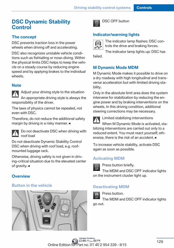
DSC Dynamic StabilityControlThe conceptDSC prevents traction loss in the powerwheels when driving off and accelerating.DSC also recognizes unstable vehicle condi‐tions such as fishtailing or nose-diving. Withinthe physical limits DSC helps to keep the vehi‐cle on a steady course by reducing enginespeed and by applying brakes to the individualwheels.
NoteAdjust your driving style to the situationAn appropriate driving style is always the
responsibility of the driver.The laws of physics cannot be repealed, noteven with DSC.Therefore, do not reduce the additional safetymargin by driving in a risky manner.◀
Do not deactivate DSC when driving withroof load
Do not deactivate Dynamic Stability ControlDSC when driving with roof load, e.g. roof-mounted luggage rack.Otherwise, driving safety is not given in driv‐ing-critical situation due to the elevated centerof gravity.◀
Overview
Button in the vehicle
DSC OFF button
Indicator/warning lightsThe indicator lamp flashes: DSC con‐trols the drive and braking forces.The indicator lamp lights up: DSC has
failed.
M Dynamic Mode MDMM Dynamic Mode makes it possible to drive ona dry roadway with high longitudinal and trans‐verse acceleration but with limited driving sta‐bility.Only in the absolute limit area does the systemintervene for stabilization by reducing the en‐gine power and by braking interventions on thewheels. In this driving condition, additionalsteering corrections may be necessary.
Limited stabilizing interventionsWhen M Dynamic Mode is activated, sta‐
bilizing interventions are carried out only to areduced extent. You must react yourself; oth‐erwise, there is the risk of an accident.◀
To increase vehicle stability, activate DSCagain as soon as possible.
Activating MDMPress button briefly.The MDM and DSC OFF indicator lights
on the instrument cluster light up.
Deactivating MDMPress button.The MDM and DSC OFF indicator lights
go out.
Seite 129
Driving stability control systems Controls
129Online Edition for Part no. 01 40 2 954 339 - II/15
Information Provided by:
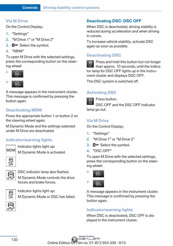
Via M DriveOn the Control Display:
1. "Settings"2. "M Drive 1" or "M Drive 2"3. Select the symbol.4. "MDM"To open M Drive with the selected settings,press the corresponding button on the steer‐ing wheel:▷
▷
A message appears in the instrument cluster.This message is confirmed by pressing thebutton again.
Deactivating MDMPress the appropriate button 1 or button 2 onthe steering wheel again.M Dynamic Mode and the settings selectedunder M Drive are deactivated.
Indicator/warning lightsIndicator lights light up:M Dynamic Mode is activated.
DSC indicator lamp also flashes:M Dynamic Mode controls the driveforces and brake forces.
Indicator lights light up:M Dynamic Mode or DSC has failed.
Deactivating DSC: DSC OFFWhen DSC is deactivated, driving stability isreduced during acceleration and when drivingin curves.To increase vehicle stability, activate DSCagain as soon as possible.
Deactivating DSCPress and hold this button but not longerthan approx. 10 seconds, until the indica‐
tor lamp for DSC OFF lights up in the instru‐ment cluster and displays DSC OFF.The DSC system is switched off.
Activating DSCPress button.DSC OFF and the DSC OFF indicator
lamp go out.
Via M DriveOn the Control Display:
1. "Settings"2. "M Drive 1" or "M Drive 2"3. Select the symbol.4. "DSC OFF"To open M Drive with the selected settings,press the corresponding button on the steer‐ing wheel:▷
▷
A message appears in the instrument cluster.This message is confirmed by pressing thebutton again.
Indicator/warning lightsWhen DSC is deactivated, DSC OFF is dis‐played in the instrument cluster.
Seite 130
Controls Driving stability control systems
130Online Edition for Part no. 01 40 2 954 339 - II/15
Information Provided by:
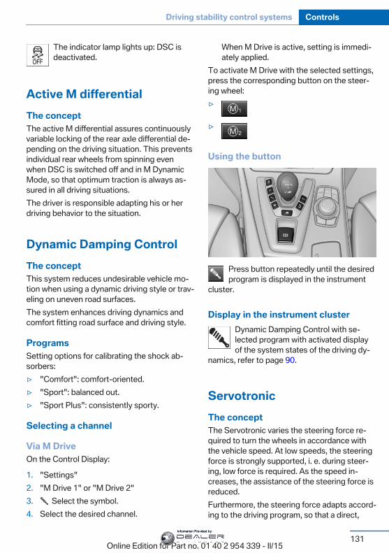
The indicator lamp lights up: DSC isdeactivated.
Active M differentialThe conceptThe active M differential assures continuouslyvariable locking of the rear axle differential de‐pending on the driving situation. This preventsindividual rear wheels from spinning evenwhen DSC is switched off and in M DynamicMode, so that optimum traction is always as‐sured in all driving situations.The driver is responsible adapting his or herdriving behavior to the situation.
Dynamic Damping ControlThe conceptThis system reduces undesirable vehicle mo‐tion when using a dynamic driving style or trav‐eling on uneven road surfaces.The system enhances driving dynamics andcomfort fitting road surface and driving style.
ProgramsSetting options for calibrating the shock ab‐sorbers:▷ "Comfort": comfort-oriented.▷ "Sport": balanced out.▷ "Sport Plus": consistently sporty.
Selecting a channel
Via M DriveOn the Control Display:
1. "Settings"2. "M Drive 1" or "M Drive 2"3. Select the symbol.4. Select the desired channel.
When M Drive is active, setting is immedi‐ately applied.
To activate M Drive with the selected settings,press the corresponding button on the steer‐ing wheel:▷
▷
Using the button
Press button repeatedly until the desiredprogram is displayed in the instrument
cluster.
Display in the instrument clusterDynamic Damping Control with se‐lected program with activated displayof the system states of the driving dy‐
namics, refer to page 90.
ServotronicThe conceptThe Servotronic varies the steering force re‐quired to turn the wheels in accordance withthe vehicle speed. At low speeds, the steeringforce is strongly supported, i. e. during steer‐ing, low force is required. As the speed in‐creases, the assistance of the steering force isreduced.Furthermore, the steering force adapts accord‐ing to the driving program, so that a direct,
Seite 131
Driving stability control systems Controls
131Online Edition for Part no. 01 40 2 954 339 - II/15
Information Provided by:

sporty feel and/or comfortable steering is con‐veyed.
ProgramsSteering force setting options:▷ "Comfort": low.▷ "Sport": medium.▷ "Sport Plus": high.
Selecting a channel
Via M DriveOn the Control Display:
1. "Settings"2. "M Drive 1" or "M Drive 2"3. Select the symbol.4. Select the desired channel.
When M Drive is active, setting is immedi‐ately applied.
To activate M Drive with the selected settings,press the corresponding button on the steer‐ing wheel:▷
▷
Using the button
Press button repeatedly until the desiredprogram is displayed in the instrument
cluster.
Display in the instrument clusterServotronic with selected program withactivated display of the System statesof the driving dynamics, refer to
page 90.
Seite 132
Controls Driving stability control systems
132Online Edition for Part no. 01 40 2 954 339 - II/15
Information Provided by:
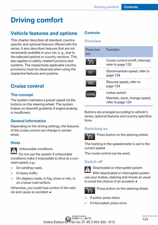
Driving comfortVehicle features and optionsThis chapter describes all standard, country-specific and optional features offered with theseries. It also describes features that are notnecessarily available in your car, e. g., due tothe selected options or country versions. Thisalso applies to safety-related functions andsystems. The respectively applicable countryprovisions must be observed when using therespective features and systems.
Cruise controlThe conceptThe system maintains a preset speed via thebuttons on the steering wheel. The systembrakes on downhill gradients if engine brakingis insufficient.
General informationDepending on the driving settings, the featuresof the cruise control can change in certainareas.
HintsUnfavorable conditionsDo not use the system if unfavorable
conditions make it impossible to drive at a con‐stant speed, e.g.:▷ On winding roads.▷ In heavy traffic.▷ On slippery roads, in fog, snow or rain, or
on a loose road surface.Otherwise, you could lose control of the vehi‐cle and cause an accident.◀
Controls
Overview
Press but‐ton
Function
Cruise control on/off, interrupt,refer to page 133
Store/maintain speed, refer topage 134
Resume speed, refer topage 134
rocker switch:Maintain, store, change speed,refer to page 134
Buttons are arranged according to vehicle'sseries, optional features and country specifica‐tions.
Switching onPress button on the steering wheel.
The marking in the speedometer is set to thecurrent speed.The cruise control can be used.
Switch offDeactivated or interrupted systemWith deactivated or interrupted system
use your brakes, steering and moves as usualto avoid the chance of an accident.◀
Press button on the steering wheel.
▷ If active: press twice.▷ If interrupted: press once.
Seite 133
Driving comfort Controls
133Online Edition for Part no. 01 40 2 954 339 - II/15
Information Provided by:
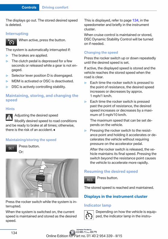
The displays go out. The stored desired speedis deleted.
InterruptingWhen active, press the button.
The system is automatically interrupted if:▷ The brakes are applied.▷ The clutch pedal is depressed for a few
seconds or released while a gear is not en‐gaged.
▷ Selector lever position D is disengaged.▷ MDM is activated or DSC is deactivated.▷ DSC is actively controlling stability.
Maintaining, storing, and changing thespeed
HintsAdjusting the desired speedModify desired speed to road conditions
and be ready to brake at all times; otherwise,there is the risk of an accident.◀
Maintaining/storing the speedPress button.Or:
Press the rocker switch while the system is in‐terrupted.When the system is switched on, the currentspeed is maintained and stored as the desiredspeed.
This is displayed, refer to page 134, in thespeedometer and briefly in the instrumentcluster.When cruise control is maintained or stored,DSC Dynamic Stability Control will be turnedon if needed.
Changing the speedPress the rocker switch up or down repeatedlyuntil the desired speed is set.If active, the displayed speed is stored and thevehicle reaches the stored speed when theroad is clear.▷ Each time the rocker switch is pressed to
the point of resistance, the desired speedincreases or decreases by approx.1 mph/1 km/h.
▷ Each time the rocker switch is pressedpast the point of resistance, the desiredspeed increases or decreases by a maxi‐mum of 5 mph/10 km/h.The maximum speed that can be set de‐pends on the vehicle.
▷ Pressing the rocker switch to the resist‐ance point and holding it accelerates or de‐celerates the vehicle without requiringpressure on the accelerator pedal.After the rocker switch is released, the ve‐hicle maintains its final speed. Pressing theswitch beyond the resistance point causesthe vehicle to accelerate more rapidly.
Resuming the desired speedPress button.
The stored speed is reached and maintained.
Displays in the instrument cluster
Indicator lampDepending on how the vehicle is equip‐ped, the indicator lamp in the instru‐
Seite 134
Controls Driving comfort
134Online Edition for Part no. 01 40 2 954 339 - II/15
Information Provided by:
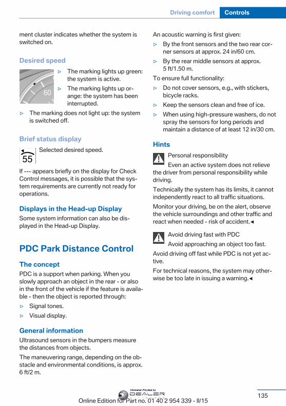
ment cluster indicates whether the system isswitched on.
Desired speed▷ The marking lights up green:
the system is active.▷ The marking lights up or‐
ange: the system has beeninterrupted.
▷ The marking does not light up: the systemis switched off.
Brief status displaySelected desired speed.
If --- appears briefly on the display for CheckControl messages, it is possible that the sys‐tem requirements are currently not ready foroperations.
Displays in the Head-up DisplaySome system information can also be dis‐played in the Head-up Display.
PDC Park Distance ControlThe conceptPDC is a support when parking. When youslowly approach an object in the rear - or alsoin the front of the vehicle if the feature is availa‐ble - then the object is reported through:▷ Signal tones.▷ Visual display.
General informationUltrasound sensors in the bumpers measurethe distances from objects.The maneuvering range, depending on the ob‐stacle and environmental conditions, is approx.6 ft/2 m.
An acoustic warning is first given:▷ By the front sensors and the two rear cor‐
ner sensors at approx. 24 in/60 cm.▷ By the rear middle sensors at approx.
5 ft/1.50 m.To ensure full functionality:▷ Do not cover sensors, e.g., with stickers,
bicycle racks.▷ Keep the sensors clean and free of ice.▷ When using high-pressure washers, do not
spray the sensors for long periods andmaintain a distance of at least 12 in/30 cm.
HintsPersonal responsibilityEven an active system does not relieve
the driver from personal responsibility whiledriving.Technically the system has its limits, it cannotindependently react to all traffic situations.Monitor your driving, be on the alert, observethe vehicle surroundings and other traffic andreact when needed - risk of accident.◀
Avoid driving fast with PDCAvoid approaching an object too fast.
Avoid driving off fast while PDC is not yet ac‐tive.For technical reasons, the system may other‐wise be too late in issuing a warning.◀
Seite 135
Driving comfort Controls
135Online Edition for Part no. 01 40 2 954 339 - II/15
Information Provided by:
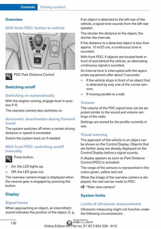
Overview
With front PDC: button in vehicle
PDC Park Distance Control
Switching on/off
Switching on automaticallyWith the engine running, engage lever in posi‐tion P R.The rearview camera also switches on.
Automatic deactivation during forwardtravelThe system switches off when a certain drivingdistance or speed is exceeded.Switch the system back on if needed.
With front PDC: switching on/offmanually
Press button.
▷ On: the LED lights up.▷ Off: the LED goes out.The rearview camera image is displayed whenthe reverse gear is engaged by pressing thebutton.
Display
Signal tonesWhen approaching an object, an intermittentsound indicates the position of the object. E. g.
if an object is detected to the left rear of thevehicle, a signal tone sounds from the left rearspeaker.The shorter the distance to the object, theshorter the intervals.If the distance to a detected object is less thanapprox. 10 in/25 cm, a continuous tone issounded.With front PDC: if objects are located both infront of and behind the vehicle, an alternatingcontinuous signal is sounded.An interval tone is interrupted with the appro‐priate equipment after about 3 seconds:▷ If the vehicle stops in front of an object that
is detected by only one of the corner sen‐sors.
▷ If moving parallel to a wall.
VolumeThe volume of the PDC signal tone can be ad‐justed similar to the sound and volume set‐tings of the radio.Settings are stored for the profile currently inuse.
Visual warningThe approach of the vehicle to an object canbe shown on the Control Display. Objects thatare farther away are already displayed on theControl Display before a signal sounds.A display appears as soon as Park DistanceControl (PDC) is activated.The range of the sensors is represented in thecolors green, yellow and red.When the image of the rearview camera is dis‐played, the reel can be made to PDC:
"Rear view camera"
System limits
Limits of ultrasonic measurementUltrasonic measuring might not function underthe following circumstances:
Seite 136
Controls Driving comfort
136Online Edition for Part no. 01 40 2 954 339 - II/15
Information Provided by:
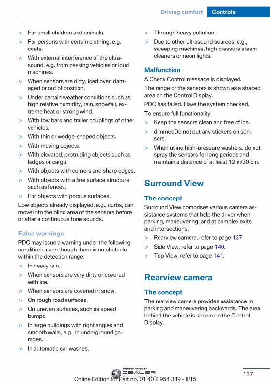
▷ For small children and animals.▷ For persons with certain clothing, e.g.
coats.▷ With external interference of the ultra‐
sound, e.g. from passing vehicles or loudmachines.
▷ When sensors are dirty, iced over, dam‐aged or out of position.
▷ Under certain weather conditions such ashigh relative humidity, rain, snowfall, ex‐treme heat or strong wind.
▷ With tow bars and trailer couplings of othervehicles.
▷ With thin or wedge-shaped objects.▷ With moving objects.▷ With elevated, protruding objects such as
ledges or cargo.▷ With objects with corners and sharp edges.▷ With objects with a fine surface structure
such as fences.▷ For objects with porous surfaces.Low objects already displayed, e.g., curbs, canmove into the blind area of the sensors beforeor after a continuous tone sounds.
False warningsPDC may issue a warning under the followingconditions even though there is no obstaclewithin the detection range:▷ In heavy rain.▷ When sensors are very dirty or covered
with ice.▷ When sensors are covered in snow.▷ On rough road surfaces.▷ On uneven surfaces, such as speed
bumps.▷ In large buildings with right angles and
smooth walls, e.g., in underground ga‐rages.
▷ In automatic car washes.
▷ Through heavy pollution.▷ Due to other ultrasound sources, e.g.,
sweeping machines, high pressure steamcleaners or neon lights.
MalfunctionA Check Control message is displayed.The range of the sensors is shown as a shadedarea on the Control Display.PDC has failed. Have the system checked.To ensure full functionality:▷ Keep the sensors clean and free of ice.▷ dimmedDo not put any stickers on sen‐
sors.▷ When using high-pressure washers, do not
spray the sensors for long periods andmaintain a distance of at least 12 in/30 cm.
Surround ViewThe conceptSurround View comprises various camera as‐sistance systems that help the driver whenparking, maneuvering, and at complex exitsand intersections.▷ Rearview camera, refer to page 137▷ Side View, refer to page 140.▷ Top View, refer to page 141.
Rearview cameraThe conceptThe rearview camera provides assistance inparking and maneuvering backwards. The areabehind the vehicle is shown on the ControlDisplay.
Seite 137
Driving comfort Controls
137Online Edition for Part no. 01 40 2 954 339 - II/15
Information Provided by:
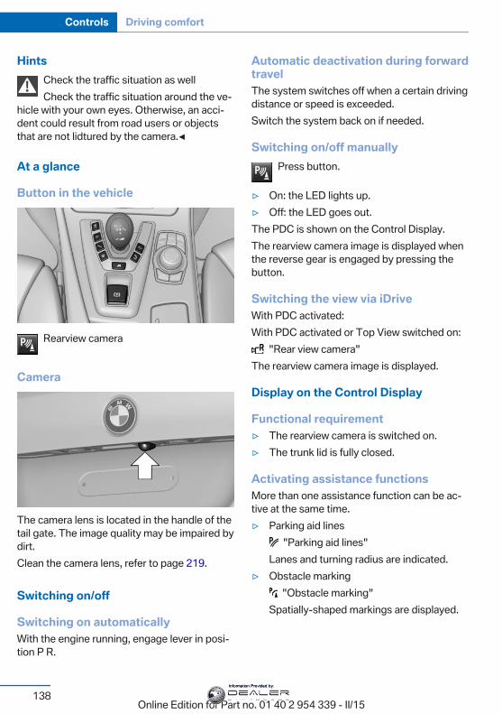
HintsCheck the traffic situation as wellCheck the traffic situation around the ve‐
hicle with your own eyes. Otherwise, an acci‐dent could result from road users or objectsthat are not lidtured by the camera.◀
At a glance
Button in the vehicle
Rearview camera
Camera
The camera lens is located in the handle of thetail gate. The image quality may be impaired bydirt.Clean the camera lens, refer to page 219.
Switching on/off
Switching on automaticallyWith the engine running, engage lever in posi‐tion P R.
Automatic deactivation during forwardtravelThe system switches off when a certain drivingdistance or speed is exceeded.Switch the system back on if needed.
Switching on/off manuallyPress button.
▷ On: the LED lights up.▷ Off: the LED goes out.The PDC is shown on the Control Display.The rearview camera image is displayed whenthe reverse gear is engaged by pressing thebutton.
Switching the view via iDriveWith PDC activated:With PDC activated or Top View switched on:
"Rear view camera"The rearview camera image is displayed.
Display on the Control Display
Functional requirement▷ The rearview camera is switched on.▷ The trunk lid is fully closed.
Activating assistance functionsMore than one assistance function can be ac‐tive at the same time.▷ Parking aid lines
"Parking aid lines"Lanes and turning radius are indicated.
▷ Obstacle marking "Obstacle marking"
Spatially-shaped markings are displayed.
Seite 138
Controls Driving comfort
138Online Edition for Part no. 01 40 2 954 339 - II/15
Information Provided by:
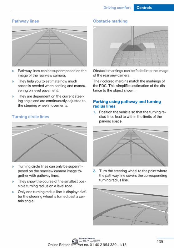
Pathway lines
▷ Pathway lines can be superimposed on theimage of the rearview camera.
▷ They help you to estimate how muchspace is needed when parking and maneu‐vering on level pavement.
▷ They are dependent on the current steer‐ing angle and are continuously adjusted tothe steering wheel movements.
Turning circle lines
▷ Turning circle lines can only be superim‐posed on the rearview camera image to‐gether with pathway lines.
▷ They show the course of the smallest pos‐sible turning radius on a level road.
▷ Only one turning radius line is displayed af‐ter the steering wheel is turned past a cer‐tain angle.
Obstacle marking
Obstacle markings can be faded into the imageof the rearview camera.Their colored margins match the markings ofthe PDC. This simplifies estimation of the dis‐tance to the object shown.
Parking using pathway and turningradius lines1. Position the vehicle so that the turning ra‐
dius lines lead to within the limits of theparking space.
2. Turn the steering wheel to the point wherethe pathway line covers the correspondingturning radius line.
Seite 139
Driving comfort Controls
139Online Edition for Part no. 01 40 2 954 339 - II/15
Information Provided by:
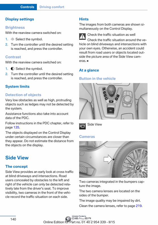
Display settings
BrightnessWith the rearview camera switched on:
1. Select the symbol.2. Turn the controller until the desired setting
is reached, and press the controller.
ContrastWith the rearview camera switched on:
1. Select the symbol.2. Turn the controller until the desired setting
is reached, and press the controller.
System limits
Detection of objectsVery low obstacles as well as high, protrudingobjects such as ledges may not be detected bythe system.Assistance functions also take into accountdata of the PDC.Follow instructions in the PDC chapter, refer topage 135.The objects displayed on the Control Displayunder certain circumstances are closer thanthey appear. Do not estimate the distance fromthe objects on the display.
Side ViewThe conceptSide View provides an early look at cross trafficat blind driveways and intersections. Roadusers concealed by obstacles to the left andright of the vehicle can only be detected rela‐tively late from the driver's seat. To improvevisibility, two cameras in the front of the vehi‐cle record the traffic situation on each side.
HintsThe images from both cameras are shown si‐multaneously on the Control Display.
Check the traffic situation as wellCheck the traffic situation around the ve‐
hicle on blind driveways and intersections withyour own eyes. Otherwise, an accident couldresult from road users or objects located out‐side the picture area of the Side View cam‐eras.◀
At a glance
Button in the vehicle
Side View
Cameras
Two cameras integrated in the bumpers cap‐ture the image.The two camera lenses are located on thesides of the bumper.The image quality may be impaired by dirt.Clean the camera lenses, refer to page 219.
Seite 140
Controls Driving comfort
140Online Edition for Part no. 01 40 2 954 339 - II/15
Information Provided by:
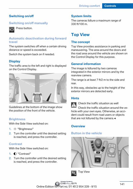
Switching on/off
Switching on/off manuallyPress button.
Automatic deactivation during forwardtravelThe system switches off when a certain drivingdistance or speed is exceeded.Switch the system back on if needed.
DisplayThe traffic area to the left and right is displayedon the Control Display.
Guidelines at the bottom of the image showthe position of the front of the vehicle.
BrightnessWith the Side View switched on:
1. "Brightness"2. Turn the controller until the desired setting
is reached, and press the controller.
ContrastWith the Side View switched on:
1. "Contrast"2. Turn the controller until the desired setting
is reached, and press the controller.
System limitsThe cameras lidture a maximum range of330 ft/100 m.
Top ViewThe conceptTop View provides assistance in parking andmaneuvering. The area around the doors andthe road area around the vehicle are shown onthe Control Display for this purpose.
General informationThe image is lidtured by two camerasintegrated in the exterior mirrors and by therearview camera.The range is at least 7 ft/2 m to the side andrear.In this way, obstacles up to the height of theexterior mirrors are detected early.
HintsCheck the traffic situation as wellCheck the traffic situation around the ve‐
hicle with your own eyes. Otherwise, an acci‐dent could result from road users or objectsthat are not lidtured by the camera.◀
Overview
Button in the vehicle
Top View
Seite 141
Driving comfort Controls
141Online Edition for Part no. 01 40 2 954 339 - II/15
Information Provided by:
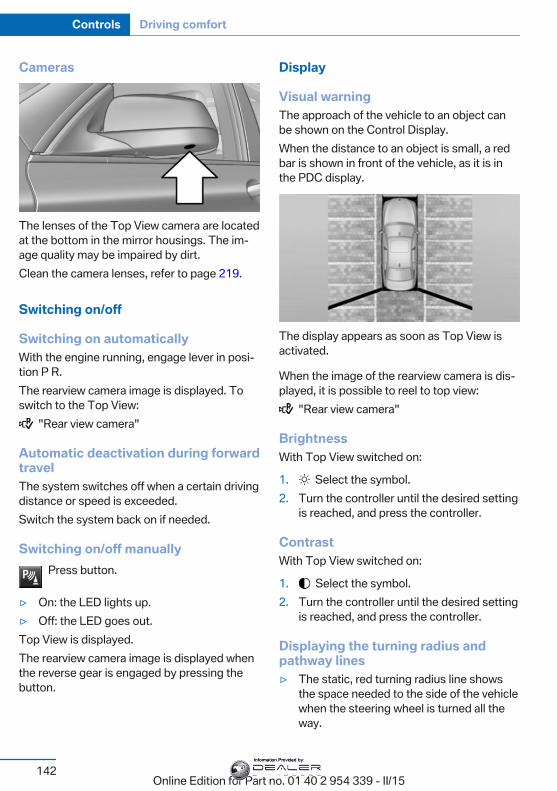
Cameras
The lenses of the Top View camera are locatedat the bottom in the mirror housings. The im‐age quality may be impaired by dirt.Clean the camera lenses, refer to page 219.
Switching on/off
Switching on automaticallyWith the engine running, engage lever in posi‐tion P R.The rearview camera image is displayed. Toswitch to the Top View:
"Rear view camera"
Automatic deactivation during forwardtravelThe system switches off when a certain drivingdistance or speed is exceeded.Switch the system back on if needed.
Switching on/off manuallyPress button.
▷ On: the LED lights up.▷ Off: the LED goes out.Top View is displayed.The rearview camera image is displayed whenthe reverse gear is engaged by pressing thebutton.
Display
Visual warningThe approach of the vehicle to an object canbe shown on the Control Display.When the distance to an object is small, a redbar is shown in front of the vehicle, as it is inthe PDC display.
The display appears as soon as Top View isactivated.
When the image of the rearview camera is dis‐played, it is possible to reel to top view:
"Rear view camera"
BrightnessWith Top View switched on:
1. Select the symbol.2. Turn the controller until the desired setting
is reached, and press the controller.
ContrastWith Top View switched on:
1. Select the symbol.2. Turn the controller until the desired setting
is reached, and press the controller.
Displaying the turning radius andpathway lines▷ The static, red turning radius line shows
the space needed to the side of the vehiclewhen the steering wheel is turned all theway.
Seite 142
Controls Driving comfort
142Online Edition for Part no. 01 40 2 954 339 - II/15
Information Provided by:
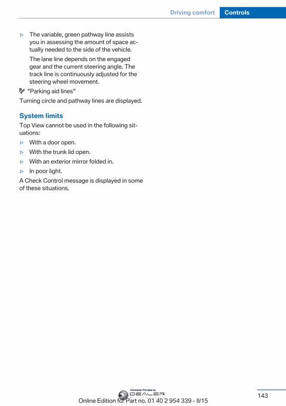
▷ The variable, green pathway line assistsyou in assessing the amount of space ac‐tually needed to the side of the vehicle.The lane line depends on the engagedgear and the current steering angle. Thetrack line is continuously adjusted for thesteering wheel movement.
"Parking aid lines"Turning circle and pathway lines are displayed.
System limitsTop View cannot be used in the following sit‐uations:▷ With a door open.▷ With the trunk lid open.▷ With an exterior mirror folded in.▷ In poor light.A Check Control message is displayed in someof these situations.
Seite 143
Driving comfort Controls
143Online Edition for Part no. 01 40 2 954 339 - II/15
Information Provided by:

Climate controlVehicle features and optionsThis chapter describes all standard, country-specific and optional features offered with theseries. It also describes features that are notnecessarily available in your car, e. g., due to
the selected options or country versions. Thisalso applies to safety-related functions andsystems. The respectively applicable countryprovisions must be observed when using therespective features and systems.
Automatic climate control
1 Air distribution, left2 Temperature, left3 AUTO program, left4 Air flow, AUTO intensity, left, residual heat5 Remove ice and condensation6 Maximum cooling7 Display8 Air flow, AUTO intensity, right9 AUTO program, right10 Temperature, right
11 Air distribution, right12 Seat heating, right 5513 Active seat ventilation, right 5614 Automatic recirculated-air control/recircu‐
lated-air mode15 Cooling function16 Rear window defroster17 SYNC program18 Active seat ventilation, left 5619 Seat heating, left 55
Seite 144
Controls Climate control
144Online Edition for Part no. 01 40 2 954 339 - II/15
Information Provided by:
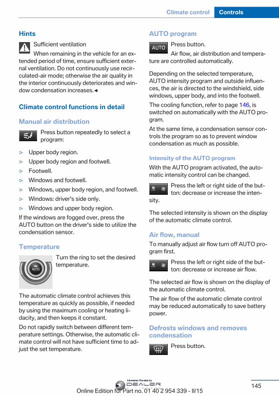
HintsSufficient ventilationWhen remaining in the vehicle for an ex‐
tended period of time, ensure sufficient exter‐nal ventilation. Do not continuously use recir‐culated-air mode; otherwise the air quality inthe interior continuously deteriorates and win‐dow condensation increases.◀
Climate control functions in detail
Manual air distributionPress button repeatedly to select aprogram:
▷ Upper body region.▷ Upper body region and footwell.▷ Footwell.▷ Windows and footwell.▷ Windows, upper body region, and footwell.▷ Windows: driver's side only.▷ Windows and upper body region.If the windows are fogged over, press theAUTO button on the driver's side to utilize thecondensation sensor.
TemperatureTurn the ring to set the desiredtemperature.
The automatic climate control achieves thistemperature as quickly as possible, if neededby using the maximum cooling or heating li‐dacity, and then keeps it constant.Do not rapidly switch between different tem‐perature settings. Otherwise, the automatic cli‐mate control will not have sufficient time to ad‐just the set temperature.
AUTO programPress button.Air flow, air distribution and tempera‐
ture are controlled automatically.
Depending on the selected temperature,AUTO intensity program and outside influen‐ces, the air is directed to the windshield, sidewindows, upper body, and into the footwell.The cooling function, refer to page 146, isswitched on automatically with the AUTO pro‐gram.At the same time, a condensation sensor con‐trols the program so as to prevent windowcondensation as much as possible.
Intensity of the AUTO programWith the AUTO program activated, the auto‐matic intensity control can be changed.
Press the left or right side of the but‐ton: decrease or increase the inten‐
sity.
The selected intensity is shown on the displayof the automatic climate control.
Air flow, manualTo manually adjust air flow turn off AUTO pro‐gram first.
Press the left or right side of the but‐ton: decrease or increase air flow.
The selected air flow is shown on the display ofthe automatic climate control.The air flow of the automatic climate controlmay be reduced automatically to save batterypower.
Defrosts windows and removescondensation
Press button.
Seite 145
Climate control Controls
145Online Edition for Part no. 01 40 2 954 339 - II/15
Information Provided by:
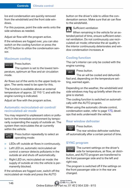
Ice and condensation are quickly removedfrom the windshield and the front side win‐dows.For this purpose, point the side vents onto theside windows as needed.
Adjust air flow with the program active.If the windows are fogged over, you can alsoswitch on the cooling function or press theAUTO button to utilize the condensation sen‐sor.
Maximum coolingPress button.The system is set to the lowest tem‐
perature, optimum air flow and air circulationmode.
Air flows out of the vents to the upper body re‐gion. The vents need to be open for this.The function is available above an externaltemperature of approx. 32 ℉/0 ℃ and with theengine running is indicated.Adjust air flow with the program active.
Automatic recirculated-air control/recirculated-air modeYou may respond to unpleasant odors or pollu‐tants in the immediate environment by tempo‐rarily suspending the supply of outside air. Thesystem then recirculates the air currentlywithin the vehicle.
Press button repeatedly to select anoperating mode:
▷ LEDs off: outside air flows in continuously.▷ Left LED on, automatic recirculated-air
control: a sensor detects pollutants in theoutside air and shuts off automatically.
▷ Right LED on, recirculated-air mode: thesupply of outside air into the vehicle is per‐manently blocked.
If the windows are fogged over, switch off therecirculated-air mode and press the AUTO
button on the driver's side to utilize the con‐densation sensor. Make sure that air can flowto the windshield.
Sufficient ventilationWhen remaining in the vehicle for an ex‐
tended period of time, ensure sufficient exter‐nal ventilation. Do not continuously use recir‐culated-air mode; otherwise the air quality inthe interior continuously deteriorates and win‐dow condensation increases.◀
Cooling functionThe car's interior can only be cooled with theengine running.
Press button.The air will be cooled and dehumidi‐
fied and, depending on the temperature set‐ting, warmed again.
Depending on the weather, the windshield andside windows may fog up briefly when the en‐gine is started.The cooling function is switched on automati‐cally with the AUTO program.When using the automatic climate control,condensation water, refer to page 173, devel‐ops that exits underneath the vehicle.
Rear window defrosterPress button.The rear window defroster switches
off automatically after a certain period of time.
SYNC programThe current settings on the driver'sside for temperature, air flow, air distri‐
bution, and AUTO program are transferred tothe front passenger side and to the left andright rear.The program is switched off if the settings onthe front passenger side or in the rear arechanged.
Seite 146
Controls Climate control
146Online Edition for Part no. 01 40 2 954 339 - II/15
Information Provided by:
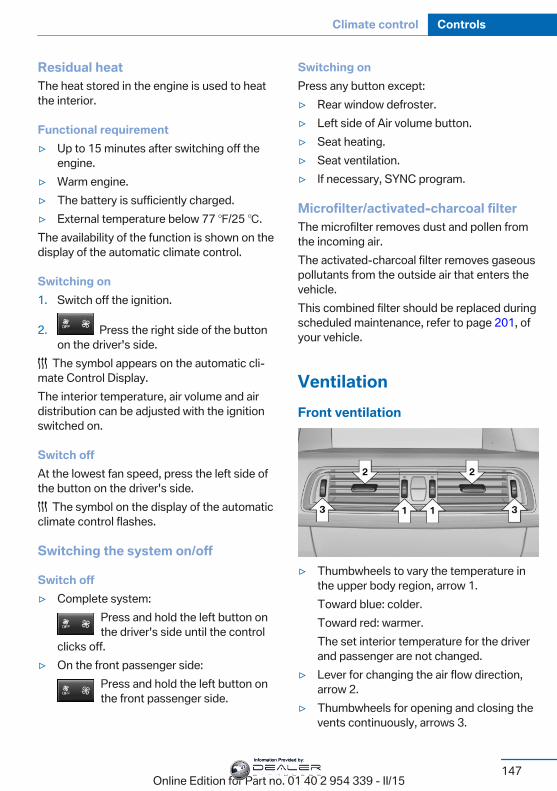
Residual heatThe heat stored in the engine is used to heatthe interior.
Functional requirement▷ Up to 15 minutes after switching off the
engine.▷ Warm engine.▷ The battery is sufficiently charged.▷ External temperature below 77 ℉/25 ℃.The availability of the function is shown on thedisplay of the automatic climate control.
Switching on1. Switch off the ignition.
2. Press the right side of the buttonon the driver's side.
The symbol appears on the automatic cli‐mate Control Display.The interior temperature, air volume and airdistribution can be adjusted with the ignitionswitched on.
Switch offAt the lowest fan speed, press the left side ofthe button on the driver's side.
The symbol on the display of the automaticclimate control flashes.
Switching the system on/off
Switch off▷ Complete system:
Press and hold the left button onthe driver's side until the control
clicks off.▷ On the front passenger side:
Press and hold the left button onthe front passenger side.
Switching onPress any button except:▷ Rear window defroster.▷ Left side of Air volume button.▷ Seat heating.▷ Seat ventilation.▷ If necessary, SYNC program.
Microfilter/activated-charcoal filterThe microfilter removes dust and pollen fromthe incoming air.The activated-charcoal filter removes gaseouspollutants from the outside air that enters thevehicle.This combined filter should be replaced duringscheduled maintenance, refer to page 201, ofyour vehicle.
VentilationFront ventilation
▷ Thumbwheels to vary the temperature inthe upper body region, arrow 1.Toward blue: colder.Toward red: warmer.The set interior temperature for the driverand passenger are not changed.
▷ Lever for changing the air flow direction,arrow 2.
▷ Thumbwheels for opening and closing thevents continuously, arrows 3.
Seite 147
Climate control Controls
147Online Edition for Part no. 01 40 2 954 339 - II/15
Information Provided by:
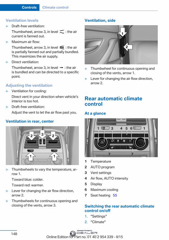
Ventilation levels▷ Draft-free ventilation:
Thumbwheel, arrow 3, in level : the aircurrent is fanned out.
▷ Maximum air flow:Thumbwheel, arrow 3, in level : the airis partially fanned out and partially bundled.This maximizes the air supply.
▷ Direct ventilation:Thumbwheel, arrow 3, in level : the airis bundled and can be directed to a specificpoint.
Adjusting the ventilation▷ Ventilation for cooling:
Direct vent in your direction when vehicle'sinterior is too hot.
▷ Draft-free ventilation:Adjust the vent to let the air flow past you.
Ventilation in rear, center
▷ Thumbwheels to vary the temperature, ar‐row 1.Toward blue: colder.Toward red: warmer.
▷ Lever for changing the air flow direction,arrow 2.
▷ Thumbwheels for continuous opening andclosing of the vents, arrow 3.
Ventilation, side
▷ Thumbwheel for continuous opening andclosing of the vents, arrow 1.
▷ Lever for changing the air flow direction,arrow 2.
Rear automatic climatecontrolAt a glance
1 Temperature2 AUTO program3 Vent settings4 Air flow, AUTO intensity5 Display6 Maximum cooling7 Seat heating 55
Switching the rear automatic climatecontrol on/off1. "Settings"2. "Climate"
Seite 148
Controls Climate control
148Online Edition for Part no. 01 40 2 954 339 - II/15
Information Provided by:
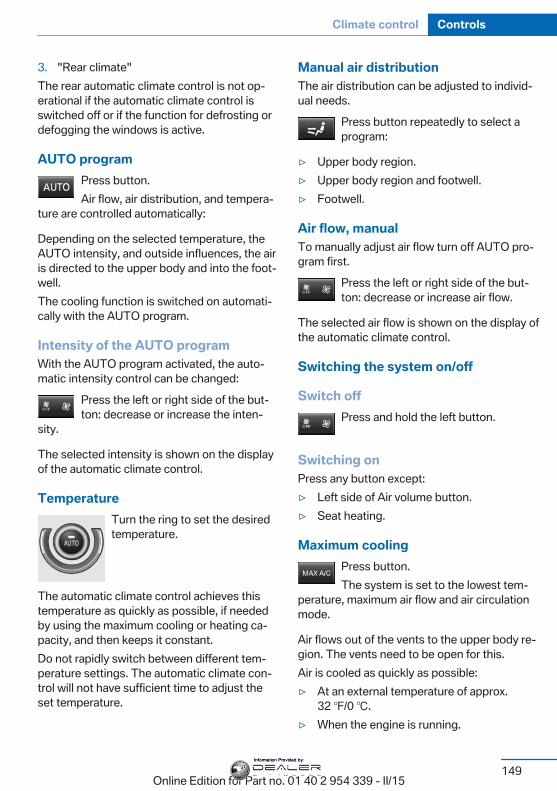
3. "Rear climate"The rear automatic climate control is not op‐erational if the automatic climate control isswitched off or if the function for defrosting ordefogging the windows is active.
AUTO programPress button.Air flow, air distribution, and tempera‐
ture are controlled automatically:
Depending on the selected temperature, theAUTO intensity, and outside influences, the airis directed to the upper body and into the foot‐well.The cooling function is switched on automati‐cally with the AUTO program.
Intensity of the AUTO programWith the AUTO program activated, the auto‐matic intensity control can be changed:
Press the left or right side of the but‐ton: decrease or increase the inten‐
sity.
The selected intensity is shown on the displayof the automatic climate control.
TemperatureTurn the ring to set the desiredtemperature.
The automatic climate control achieves thistemperature as quickly as possible, if neededby using the maximum cooling or heating ca‐pacity, and then keeps it constant.Do not rapidly switch between different tem‐perature settings. The automatic climate con‐trol will not have sufficient time to adjust theset temperature.
Manual air distributionThe air distribution can be adjusted to individ‐ual needs.
Press button repeatedly to select aprogram:
▷ Upper body region.▷ Upper body region and footwell.▷ Footwell.
Air flow, manualTo manually adjust air flow turn off AUTO pro‐gram first.
Press the left or right side of the but‐ton: decrease or increase air flow.
The selected air flow is shown on the display ofthe automatic climate control.
Switching the system on/off
Switch offPress and hold the left button.
Switching onPress any button except:▷ Left side of Air volume button.▷ Seat heating.
Maximum coolingPress button.The system is set to the lowest tem‐
perature, maximum air flow and air circulationmode.
Air flows out of the vents to the upper body re‐gion. The vents need to be open for this.Air is cooled as quickly as possible:▷ At an external temperature of approx.
32 ℉/0 ℃.▷ When the engine is running.
Seite 149
Climate control Controls
149Online Edition for Part no. 01 40 2 954 339 - II/15
Information Provided by:
Parked-car ventilationThe conceptThe parked-car ventilation ventilates the vehi‐cle interior and lowers its temperature, ifneeded.Operation can be performed via iDrive.
Functional requirements
Parked-car ventilation▷ Using the preset reel-on time or when op‐
erated directly: any external temperature.Open the vents to allow air to flow out.
Switching on/off directlyOn the Control Display:
1. "Settings"2. "Climate"3. "Activate comf. ventilation"
The symbol on the automatic climate con‐trol flashes if the system is switched on.The system continues to run for some time af‐ter being switched off.
Preselecting the reel-on timeOn the Control Display:
1. "Settings"2. "Climate"3. "Timer 1:" or "Timer 2:"4. Set the desired time.
Activating the reel-on timeOn the Control Display:
1. "Settings"2. "Climate"3. "Activate timer 1" or "Activate timer 2"
The symbol on the automatic climate con‐trol lights up when the reel-on time is acti‐vated.
The symbol on the automatic climate con‐trol flashes when the system has beenswitched on.The system will only be switched on within thenext 24 hours. After that, it needs to be reacti‐vated.
Seite 150
Controls Climate control
150Online Edition for Part no. 01 40 2 954 339 - II/15
Information Provided by:
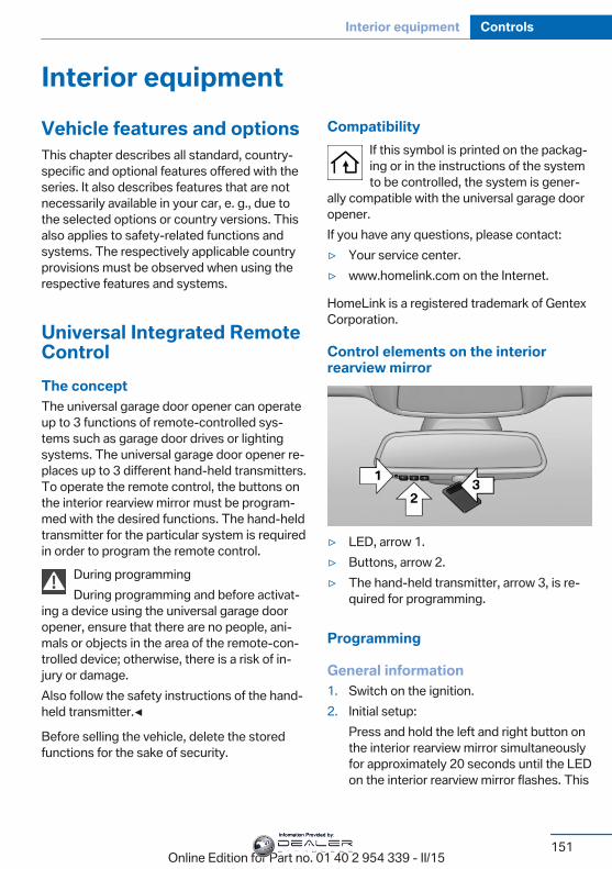
Interior equipmentVehicle features and optionsThis chapter describes all standard, country-specific and optional features offered with theseries. It also describes features that are notnecessarily available in your car, e. g., due tothe selected options or country versions. Thisalso applies to safety-related functions andsystems. The respectively applicable countryprovisions must be observed when using therespective features and systems.
Universal Integrated RemoteControlThe conceptThe universal garage door opener can operateup to 3 functions of remote-controlled sys‐tems such as garage door drives or lightingsystems. The universal garage door opener re‐places up to 3 different hand-held transmitters.To operate the remote control, the buttons onthe interior rearview mirror must be program‐med with the desired functions. The hand-heldtransmitter for the particular system is requiredin order to program the remote control.
During programmingDuring programming and before activat‐
ing a device using the universal garage dooropener, ensure that there are no people, ani‐mals or objects in the area of the remote-con‐trolled device; otherwise, there is a risk of in‐jury or damage.Also follow the safety instructions of the hand-held transmitter.◀
Before selling the vehicle, delete the storedfunctions for the sake of security.
CompatibilityIf this symbol is printed on the packag‐ing or in the instructions of the systemto be controlled, the system is gener‐
ally compatible with the universal garage dooropener.If you have any questions, please contact:▷ Your service center.▷ www.homelink.com on the Internet.
HomeLink is a registered trademark of GentexCorporation.
Control elements on the interiorrearview mirror
▷ LED, arrow 1.▷ Buttons, arrow 2.▷ The hand-held transmitter, arrow 3, is re‐
quired for programming.
Programming
General information1. Switch on the ignition.2. Initial setup:
Press and hold the left and right button onthe interior rearview mirror simultaneouslyfor approximately 20 seconds until the LEDon the interior rearview mirror flashes. This
Seite 151
Interior equipment Controls
151Online Edition for Part no. 01 40 2 954 339 - II/15
Information Provided by:
erases all programming of the buttons onthe interior rearview mirror.
3. Hold the hand-held transmitter for the sys‐tem to be controlled approx. 1 to 3 in/2.5 to8 cm away from the buttons of the interiorrearview mirror. The required distance de‐pends on the manual transmitter.
4. Simultaneously press and hold the buttonof the desired function on the hand-heldtransmitter and the button to be program‐med on the interior rearview mirror. TheLED on the interior rearview mirror will be‐gin flashing slowly.
5. Release both buttons as soon as the LEDflashes more rapidly. The LED flashingfaster indicates that the button on the inte‐rior rearview mirror has been programmed.If the LED does not flash faster after atleast 60 seconds, change the distance be‐tween the interior rearview mirror and thehand-held transmitter and repeat the step.Several more attempts at different distan‐ces may be necessary. Wait at least15 seconds between attempts.Canada: if programming with the hand-held transmitter was interrupted, holddown the interior rearview mirror buttonand repeatedly press and release thehand-held transmitter button for 2 sec‐onds.
6. To program other functions on other but‐tons, repeat steps 3 to 5.
The systems can be controlled using the inte‐rior rearview mirror buttons.
Special feature of the alternating-code wireless systemIf you are unable to operate the system afterrepeated programming, please check if thesystem to be controlled features an alternat‐ing-code system.Read the system's operating manual, or pressthe programmed button on the interior rear‐view mirror longer. If the LED on the interior
rearview mirror starts flashing rapidly and thenstays lit constantly for 2 seconds, the systemfeatures an alternating-code system. Flashingand continuous illumination of the LED will re‐peat for approximately 20 seconds.For systems with an alternating-code system,the universal garage door opener and the sys‐tem also have to be synchronized.Please read the operating manual to find outhow to synchronize the system.Synchronizing is easier with the aid of a sec‐ond person.To synchronize:
1. Park the vehicle within range of the re‐mote-controlled system.
2. Program the relevant button on the interiorrearview mirror as described.
3. Locate and press the synchronizing buttonon the system being programmed. Youhave approx. 30 seconds for the next step.
4. Hold down the programmed button on theinterior rearview mirror for approximately3 seconds and then release it. If necessary,repeat this step up to three times in orderto finish synchronization. Once synchroni‐zation is complete, the programmed func‐tion will be carried out.
Reprogramming individual buttons1. Switch on the ignition.2. Press and hold the interior rearview mirror
button to be programmed.3. As soon as the interior rearview mirror LED
starts flashing slowly, hold the hand-heldtransmitter for the system to be controlledapprox. 1 to 3 in/2.5 to 8 cm away from thebuttons of the interior rearview mirror. Therequired distance depends on the manualtransmitter.
Seite 152
Controls Interior equipment
152Online Edition for Part no. 01 40 2 954 339 - II/15
Information Provided by:

4. Likewise, press and hold the button of thedesired function on the hand-held trans‐mitter.
5. Release both buttons as soon as the inte‐rior rearview mirror LED flashes more rap‐idly. The LED flashing faster indicates thatthe button on the interior rearview mirrorhas been programmed. The system canthen be controlled by the button on the in‐terior rearview mirror.If the LED does not flash faster after atleast 60 seconds, change the distance andrepeat the step. Several more attempts atdifferent distances may be necessary. Waitat least 15 seconds between attempts.Canada: if programming with the hand-held transmitter was interrupted, holddown the interior rearview mirror buttonand repeatedly press and release thehand-held transmitter button for 2 sec‐onds.
ControlsBefore operationBefore operating a system using the uni‐
versal garage door opener, ensure that thereare no people, animals, or objects within therange of movement of the remote-controlledsystem; otherwise, there is a risk of injury ordamage.Also follow the safety instructions of the hand-held transmitter.◀
The system, such as the garage door, can beoperated using the button on the interior rear‐view mirror while the engine is running or whenthe ignition is started. To do this, hold downthe button within receiving range of the systemuntil the function is activated. The interior rear‐view mirror LED stays lit while the wireless sig‐nal is being transmitted.
Deleting stored functionsPress and hold the left and right button on theinterior rearview mirror simultaneously for ap‐
proximately 20 seconds until the LED flashesrapidly. All stored functions are deleted. Thefunctions cannot be deleted individually.
Sun visorGlare shieldFold the sun visor down or up.
Vanity mirrorA vanity mirror is located in the sun visor be‐hind a cover. When the cover is opened, themirror lighting switches on.
Ashtray/cigarette lighterManual transmission: Front
Opening
Press on the cover.
EmptyingTake out the insert.
LighterPush in the lighter.The lighter can be removed assoon as it pops back out.
Seite 153
Interior equipment Controls
153Online Edition for Part no. 01 40 2 954 339 - II/15
Information Provided by:
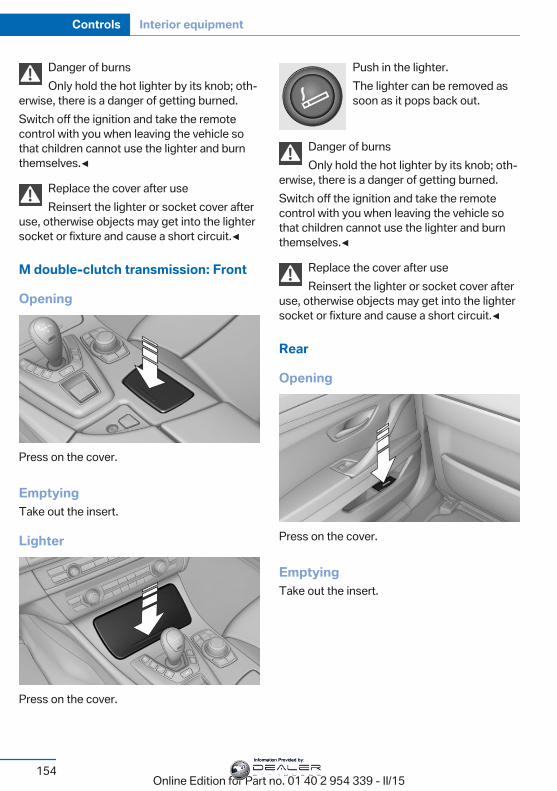
Danger of burnsOnly hold the hot lighter by its knob; oth‐
erwise, there is a danger of getting burned.Switch off the ignition and take the remotecontrol with you when leaving the vehicle sothat children cannot use the lighter and burnthemselves.◀
Replace the cover after useReinsert the lighter or socket cover after
use, otherwise objects may get into the lightersocket or fixture and cause a short circuit.◀
M double-clutch transmission: Front
Opening
Press on the cover.
EmptyingTake out the insert.
Lighter
Press on the cover.
Push in the lighter.The lighter can be removed assoon as it pops back out.
Danger of burnsOnly hold the hot lighter by its knob; oth‐
erwise, there is a danger of getting burned.Switch off the ignition and take the remotecontrol with you when leaving the vehicle sothat children cannot use the lighter and burnthemselves.◀
Replace the cover after useReinsert the lighter or socket cover after
use, otherwise objects may get into the lightersocket or fixture and cause a short circuit.◀
Rear
Opening
Press on the cover.
EmptyingTake out the insert.
Seite 154
Controls Interior equipment
154Online Edition for Part no. 01 40 2 954 339 - II/15
Information Provided by:
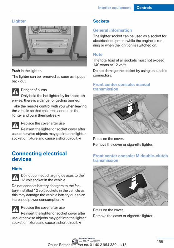
Lighter
Push in the lighter.The lighter can be removed as soon as it popsback out.
Danger of burnsOnly hold the hot lighter by its knob; oth‐
erwise, there is a danger of getting burned.Take the remote control with you when leavingthe vehicle so that children cannot use thelighter and burn themselves.◀
Replace the cover after useReinsert the lighter or socket cover after
use, otherwise objects may get into the lightersocket or fixture and cause a short circuit.◀
Connecting electricaldevicesHints
Do not connect charging devices to the12 volt socket in the vehicle
Do not connect battery chargers to the fac‐tory-installed 12 volt sockets in the vehicle asthis may damage the vehicle battery due to anincreased power consumption.◀
Replace the cover after useReinsert the lighter or socket cover after
use, otherwise objects may get into the lightersocket or fixture and cause a short circuit.◀
Sockets
General informationThe lighter socket can be used as a socket forelectrical equipment while the engine is run‐ning or when the ignition is switched on.
NoteThe total load of all sockets must not exceed140 watts at 12 volts.Do not damage the socket by using unsuitableconnectors.
Front center console: manualtransmission
Press on the cover.Remove the cover or cigarette lighter.
Front center console: M double-clutchtransmission
Press on the cover.Remove the cover or cigarette lighter.
Seite 155
Interior equipment Controls
155Online Edition for Part no. 01 40 2 954 339 - II/15
Information Provided by:
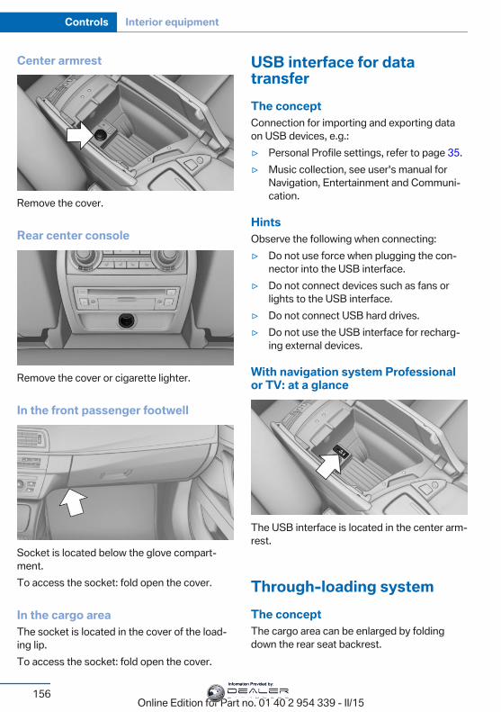
Center armrest
Remove the cover.
Rear center console
Remove the cover or cigarette lighter.
In the front passenger footwell
Socket is located below the glove compart‐ment.To access the socket: fold open the cover.
In the cargo areaThe socket is located in the cover of the load‐ing lip.To access the socket: fold open the cover.
USB interface for datatransferThe conceptConnection for importing and exporting dataon USB devices, e.g.:▷ Personal Profile settings, refer to page 35.▷ Music collection, see user's manual for
Navigation, Entertainment and Communi‐cation.
HintsObserve the following when connecting:▷ Do not use force when plugging the con‐
nector into the USB interface.▷ Do not connect devices such as fans or
lights to the USB interface.▷ Do not connect USB hard drives.▷ Do not use the USB interface for recharg‐
ing external devices.
With navigation system Professionalor TV: at a glance
The USB interface is located in the center arm‐rest.
Through-loading systemThe conceptThe cargo area can be enlarged by foldingdown the rear seat backrest.
Seite 156
Controls Interior equipment
156Online Edition for Part no. 01 40 2 954 339 - II/15
Information Provided by:
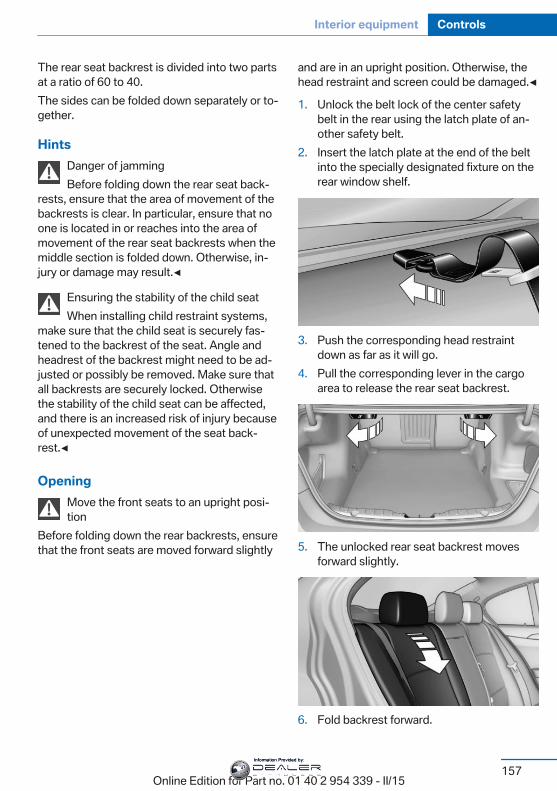
The rear seat backrest is divided into two partsat a ratio of 60 to 40.The sides can be folded down separately or to‐gether.
HintsDanger of jammingBefore folding down the rear seat back‐
rests, ensure that the area of movement of thebackrests is clear. In particular, ensure that noone is located in or reaches into the area ofmovement of the rear seat backrests when themiddle section is folded down. Otherwise, in‐jury or damage may result.◀
Ensuring the stability of the child seatWhen installing child restraint systems,
make sure that the child seat is securely fas‐tened to the backrest of the seat. Angle andheadrest of the backrest might need to be ad‐justed or possibly be removed. Make sure thatall backrests are securely locked. Otherwisethe stability of the child seat can be affected,and there is an increased risk of injury becauseof unexpected movement of the seat back‐rest.◀
OpeningMove the front seats to an upright posi‐tion
Before folding down the rear backrests, ensurethat the front seats are moved forward slightly
and are in an upright position. Otherwise, thehead restraint and screen could be damaged.◀
1. Unlock the belt lock of the center safetybelt in the rear using the latch plate of an‐other safety belt.
2. Insert the latch plate at the end of the beltinto the specially designated fixture on therear window shelf.
3. Push the corresponding head restraintdown as far as it will go.
4. Pull the corresponding lever in the cargoarea to release the rear seat backrest.
5. The unlocked rear seat backrest movesforward slightly.
6. Fold backrest forward.
Seite 157
Interior equipment Controls
157Online Edition for Part no. 01 40 2 954 339 - II/15
Information Provided by:
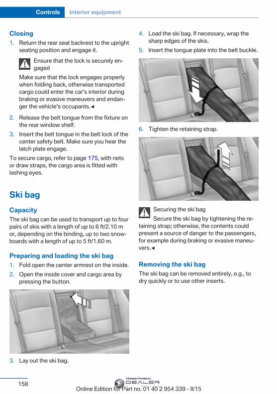
Closing1. Return the rear seat backrest to the upright
seating position and engage it.Ensure that the lock is securely en‐gaged
Make sure that the lock engages properlywhen folding back, otherwise transportedcargo could enter the car's interior duringbraking or evasive maneuvers and endan‐ger the vehicle's occupants.◀
2. Release the belt tongue from the fixture onthe rear window shelf.
3. Insert the belt tongue in the belt lock of thecenter safety belt. Make sure you hear thelatch plate engage.
To secure cargo, refer to page 175, with netsor draw straps, the cargo area is fitted withlashing eyes.
Ski bagCapacityThe ski bag can be used to transport up to fourpairs of skis with a length of up to 6 ft/2.10 mor, depending on the binding, up to two snow‐boards with a length of up to 5 ft/1.60 m.
Preparing and loading the ski bag1. Fold open the center armrest on the inside.2. Open the inside cover and cargo area by
pressing the button.
3. Lay out the ski bag.
4. Load the ski bag. If necessary, wrap thesharp edges of the skis.
5. Insert the tongue plate into the belt buckle.
6. Tighten the retaining strap.
Securing the ski bagSecure the ski bag by tightening the re‐
taining strap; otherwise, the contents couldpresent a source of danger to the passengers,for example during braking or evasive maneu‐vers.◀
Removing the ski bagThe ski bag can be removed entirely, e.g., todry quickly or to use other inserts.
Seite 158
Controls Interior equipment
158Online Edition for Part no. 01 40 2 954 339 - II/15
Information Provided by:
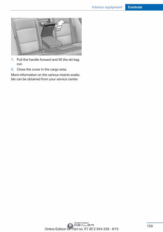
1. Pull the handle forward and lift the ski bagout.
2. Close the cover in the cargo area.More information on the various inserts availa‐ble can be obtained from your service center.
Seite 159
Interior equipment Controls
159Online Edition for Part no. 01 40 2 954 339 - II/15
Information Provided by:
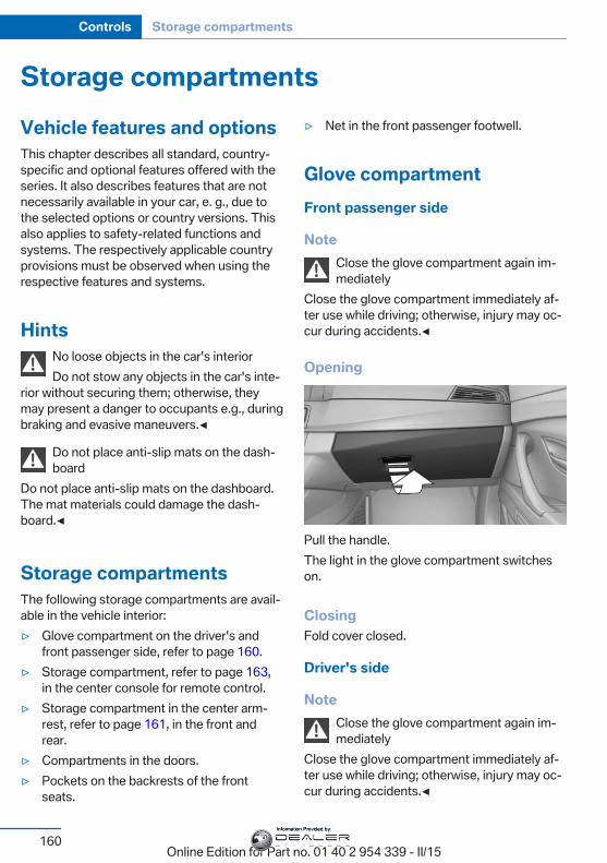
Storage compartmentsVehicle features and optionsThis chapter describes all standard, country-specific and optional features offered with theseries. It also describes features that are notnecessarily available in your car, e. g., due tothe selected options or country versions. Thisalso applies to safety-related functions andsystems. The respectively applicable countryprovisions must be observed when using therespective features and systems.
HintsNo loose objects in the car's interiorDo not stow any objects in the car's inte‐
rior without securing them; otherwise, theymay present a danger to occupants e.g., duringbraking and evasive maneuvers.◀
Do not place anti-slip mats on the dash‐board
Do not place anti-slip mats on the dashboard.The mat materials could damage the dash‐board.◀
Storage compartmentsThe following storage compartments are avail‐able in the vehicle interior:▷ Glove compartment on the driver's and
front passenger side, refer to page 160.▷ Storage compartment, refer to page 163,
in the center console for remote control.▷ Storage compartment in the center arm‐
rest, refer to page 161, in the front andrear.
▷ Compartments in the doors.▷ Pockets on the backrests of the front
seats.
▷ Net in the front passenger footwell.
Glove compartmentFront passenger side
NoteClose the glove compartment again im‐mediately
Close the glove compartment immediately af‐ter use while driving; otherwise, injury may oc‐cur during accidents.◀
Opening
Pull the handle.The light in the glove compartment switcheson.
ClosingFold cover closed.
Driver's side
NoteClose the glove compartment again im‐mediately
Close the glove compartment immediately af‐ter use while driving; otherwise, injury may oc‐cur during accidents.◀
Seite 160
Controls Storage compartments
160Online Edition for Part no. 01 40 2 954 339 - II/15
Information Provided by:
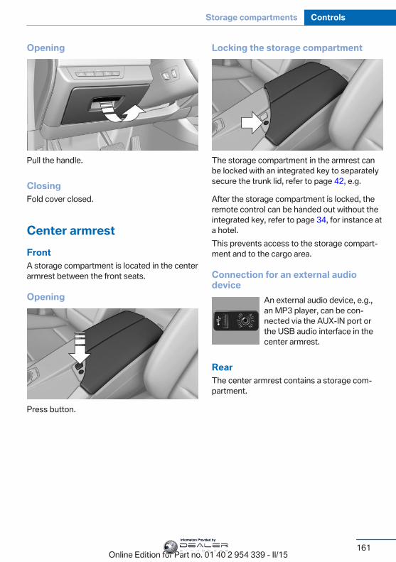
Opening
Pull the handle.
ClosingFold cover closed.
Center armrestFrontA storage compartment is located in the centerarmrest between the front seats.
Opening
Press button.
Locking the storage compartment
The storage compartment in the armrest canbe locked with an integrated key to separatelysecure the trunk lid, refer to page 42, e.g.
After the storage compartment is locked, theremote control can be handed out without theintegrated key, refer to page 34, for instance ata hotel.This prevents access to the storage compart‐ment and to the cargo area.
Connection for an external audiodevice
An external audio device, e.g.,an MP3 player, can be con‐nected via the AUX-IN port orthe USB audio interface in thecenter armrest.
RearThe center armrest contains a storage com‐partment.
Seite 161
Storage compartments Controls
161Online Edition for Part no. 01 40 2 954 339 - II/15
Information Provided by:
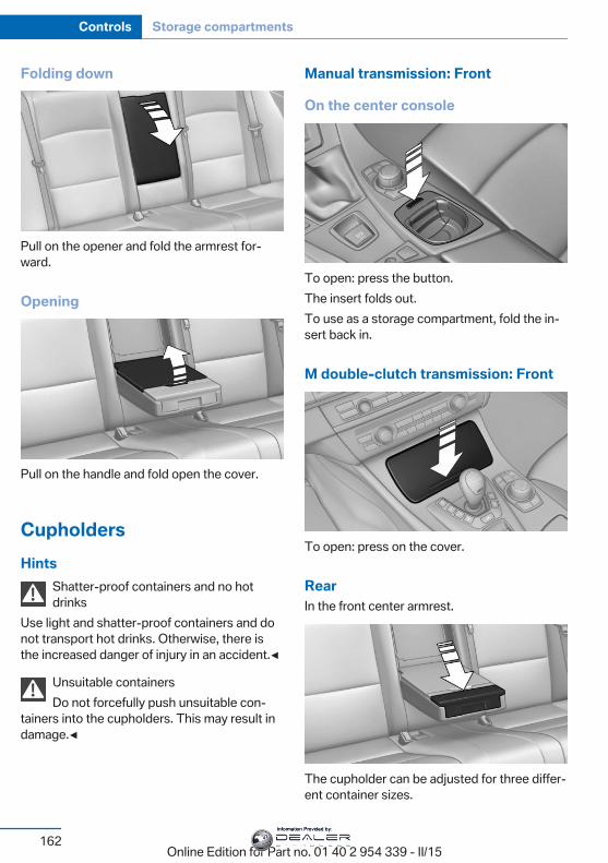
Folding down
Pull on the opener and fold the armrest for‐ward.
Opening
Pull on the handle and fold open the cover.
CupholdersHints
Shatter-proof containers and no hotdrinks
Use light and shatter-proof containers and donot transport hot drinks. Otherwise, there isthe increased danger of injury in an accident.◀
Unsuitable containersDo not forcefully push unsuitable con‐
tainers into the cupholders. This may result indamage.◀
Manual transmission: Front
On the center console
To open: press the button.The insert folds out.To use as a storage compartment, fold the in‐sert back in.
M double-clutch transmission: Front
To open: press on the cover.
RearIn the front center armrest.
The cupholder can be adjusted for three differ‐ent container sizes.
Seite 162
Controls Storage compartments
162Online Edition for Part no. 01 40 2 954 339 - II/15
Information Provided by:
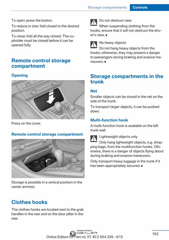
To open: press the button.To reduce in size: fold closed to the desiredposition.To close: fold all the way closed. The cu‐pholder must be closed before it can beopened fully.
Remote control storagecompartmentOpening
Press on the cover.
Remote control storage compartment
Storage is possible in a vertical position in thecenter armrest.
Clothes hooksThe clothes hooks are located next to the grabhandles in the rear and on the door pillar in therear.
Do not obstruct viewWhen suspending clothing from the
hooks, ensure that it will not obstruct the driv‐er's view.◀
No heavy objectsDo not hang heavy objects from the
hooks; otherwise, they may present a dangerto passengers during braking and evasive ma‐neuvers.◀
Storage compartments in thetrunkNetSmaller objects can be stored in the net on theside of the trunk.To transport larger objects, it can be pusheddown.
Multi-function hookA multi-function hook is available on the lefttrunk wall.
Lightweight objects onlyOnly hang lightweight objects, e.g. shop‐
ping bags, from the multifunction hooks. Oth‐erwise, there is a danger of objects flying aboutduring braking and evasive maneuvers.Only transport heavy luggage in the trunk if ithas been appropriately secured.◀
Seite 163
Storage compartments Controls
163Online Edition for Part no. 01 40 2 954 339 - II/15
Information Provided by:
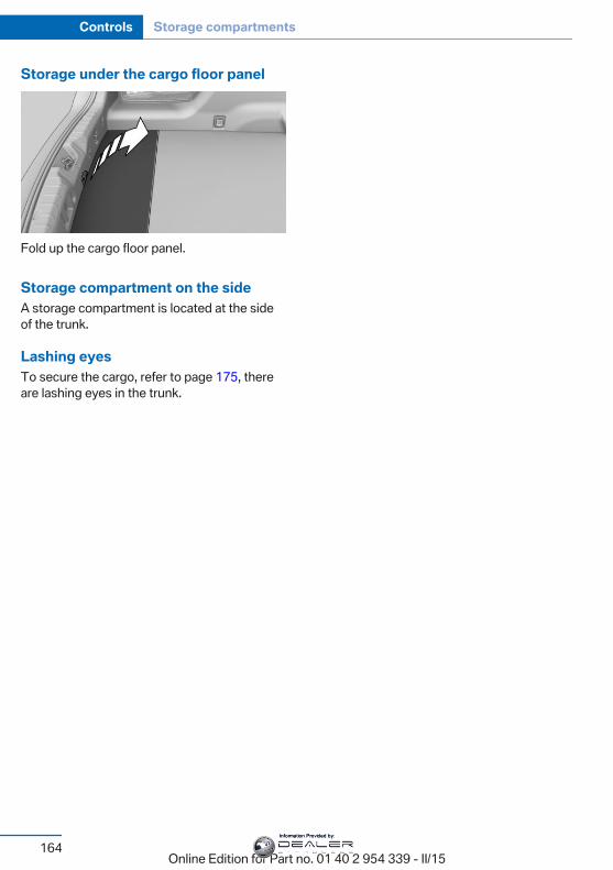
Storage under the cargo floor panel
Fold up the cargo floor panel.
Storage compartment on the sideA storage compartment is located at the sideof the trunk.
Lashing eyesTo secure the cargo, refer to page 175, thereare lashing eyes in the trunk.
Seite 164
Controls Storage compartments
164Online Edition for Part no. 01 40 2 954 339 - II/15
Information Provided by:

Seite 165
Storage compartments Controls
165Online Edition for Part no. 01 40 2 954 339 - II/15
Information Provided by:
Online Edition for Part no. 01 40 2 954 339 - II/15
Information Provided by:
Driving tipsThis chapter provides you with information
useful in dealing with specific driving andoperating modes.
Online Edition for Part no. 01 40 2 954 339 - II/15
Information Provided by:
BMW M5 technologyVehicle features and optionsThis chapter describes all standard, country-specific and optional features offered with theseries. It also describes features that are notnecessarily available in your car, e. g., due tothe selected options or country versions. Thisalso applies to safety-related functions andsystems. The respectively applicable countryprovisions must be observed when using therespective features and systems.
V8 high-performance engineThe high-performance V8 engine gets a maxi‐mum power of 412 kW, with CompetitionPackage 423 kW, from a displacement of4.4 liters and a maximum torque of 680 Nm.With its spontaneous response behavior, aspeed range of wide utility results. The maxi‐mum engine speed is 7,200 rpm and is elec‐tronically controlled. Because of the high en‐gine dynamics, the maximum engine speedwith the vehicle stationary is reduced.
Warm-upDuring the engine warm-up phase, theV8 high-performance engine has a somewhatrougher running behavior because of the emis‐sion controls.When the engine is cold, the exhaust systemhas a slightly metallic undertone due to the na‐ture of the system.For more information about the warm-up pro‐cedure: Engine speed, refer to page 87, andengine oil temperature, refer to page 87.
Compound brakeThe high-performance braking system hasperforated compound brake discs.
Because of particular structural characteristics,there may be operation-related noises duringbraking. However, this has no effect on per‐formance, operational reliability and reliabilityof the brake.
Correct brakingTo keep the brake system in optimum condi‐tion, it is expedient to apply them at regular in‐tervals corresponding to the vehicle character.
M carbon ceramic brakeThe high-performance braking system hasperforated carbon-ceramic brake disks and isdesigned for use on racetracks.Due to properties of the materials used, brak‐ing may be associated with louder functionnoises, particularly in wet conditions, just be‐fore the vehicle comes to a stop. However, thishas no effect on the performance, operationalreliability and durability of the brake.The effects of moisture and road salt, from us‐ing a carwash or dew formation overnight e.g.,may render the braking effect comparable tothat of a conventional braking system. Thismay be perceived as reduced braking effectand can be compensated for if needed bypressing the brake pedal harder.Before washing the vehicle in an automaticcarwash or wash tunnel, clean the brake discsand brake calipers with a steam jet or high-pressure washer as well, to prevent encrusta‐tions and dirt buildups, caused by salt crystals,e.g., if the car is immobile afterwards. Thecleaning effect of automatic carwashes orwash tunnels is usually not adequate for this inthe area around the wheels.To do this, also follow the instructions inWashing the vehicle, refer to page 216, andBraking safely, refer to page 172.
Seite 168
Driving tips BMW M5 technology
168Online Edition for Part no. 01 40 2 954 339 - II/15
Information Provided by:
DrivetrainWith this vehicle, particular value was placedon the direct connection from engine to thedrivetrain. Due to the torsionally rigid design ofthe drivetrain, as is typical in a sports car, thetransmission of the torque also gives acousticfeedback.When there are load changes, this may resultin clicking noises. The do not cause any im‐pairment of the operation or the service life ofthe components.
Driving on racetracksRequirementsBefore driving on a racetrack:▷ Participation in BMW Driver Experience
Training.▷ Check engine oil fill level and replenish as
necessary.▷ Have vehicle checked at a service center.
HintsRacetrack operation leads to increased wear.The vehicle is not designed for motorsportscompetitive use. This wear is not covered bythe warranty.The standard brake linings and the wear indi‐cators are not designed for racetrack opera‐tion. For more information and advice, contactyour service center.
Seite 169
BMW M5 technology Driving tips
169Online Edition for Part no. 01 40 2 954 339 - II/15
Information Provided by:
Things to remember when drivingVehicle features and optionsThis chapter describes all standard, country-specific and optional features offered with theseries. It also describes features that are notnecessarily available in your car, e. g., due tothe selected options or country versions. Thisalso applies to safety-related functions andsystems. The respectively applicable countryprovisions must be observed when using therespective features and systems.
Breaking-in periodGeneral informationMoving parts need time to adjust to one an‐other (break-in time).The following instructions will help accomplisha long vehicle life and good efficiency.During break-in, do not use the Launch Con‐trol, refer to page 80.
Engine, transmission, and axle drive
Up to 1,200 miles/2,000 kmDrive at varying engine and road speeds, butdo not exceed 5,500 rpm and106 mph/170 km/h.Avoid full load or kickdown under all circum‐stances.
At 1,200 miles/2,000 kmHave drive-in checkup maintenance per‐formed.
From 1,200 miles/2,000 km to3,100 miles/5,000 kmThe engine and road speed can gradually beincreased to a constant speed of137 mph/220 km/h.
Use the maximum speed of 155 mph/250 km/honly briefly, e.g., when passing.
TiresTire traction is not optimal due to manufactur‐ing circumstances when tires are brand-new;they achieve their full traction potential after abreak-in time.Drive conservatively for the first200 miles/300 km.
Brake systemM Compound brakes require an initial break-inperiod of approx. 300 miles/500 km to achieveoptimal performance between brake discs andbrake pads. Drive moderately during thisbreak-in period.M carbon ceramic brakes require an initialbreak-in period of approx. 600 miles/1,000 kmto achieve optimal performance between brakediscs and brake pads. Drive moderately duringthis break-in period.
ClutchThe function of the clutch reaches its optimallevel only after a distance driven of approx.300 miles/500 km. During this break-in period,engage the clutch gently.
Following part replacementThe same break-in procedures should be ob‐served if any of the components above-men‐tioned have to be renewed in the course of thevehicle's operating life.
Seite 170
Driving tips Things to remember when driving
170Online Edition for Part no. 01 40 2 954 339 - II/15
Information Provided by:
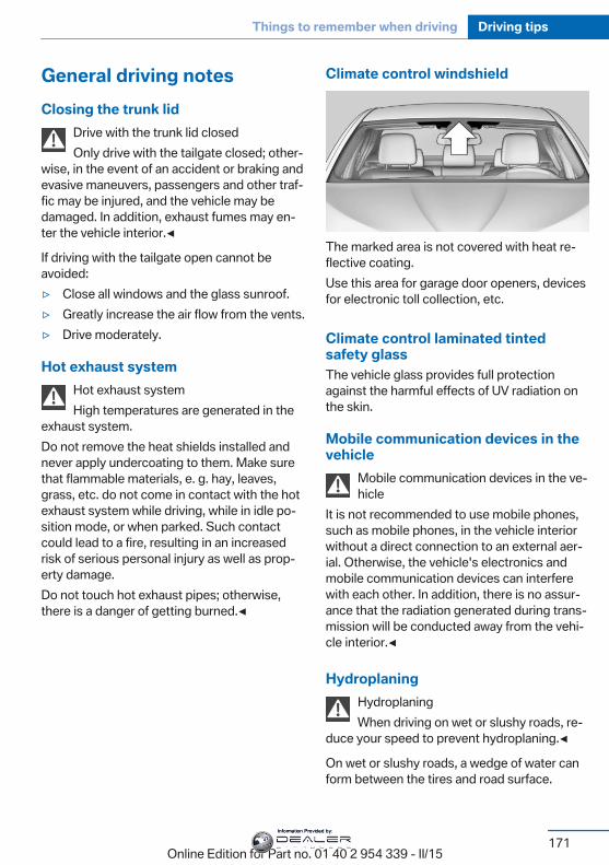
General driving notesClosing the trunk lid
Drive with the trunk lid closedOnly drive with the tailgate closed; other‐
wise, in the event of an accident or braking andevasive maneuvers, passengers and other traf‐fic may be injured, and the vehicle may bedamaged. In addition, exhaust fumes may en‐ter the vehicle interior.◀
If driving with the tailgate open cannot beavoided:▷ Close all windows and the glass sunroof.▷ Greatly increase the air flow from the vents.▷ Drive moderately.
Hot exhaust systemHot exhaust systemHigh temperatures are generated in the
exhaust system.Do not remove the heat shields installed andnever apply undercoating to them. Make surethat flammable materials, e. g. hay, leaves,grass, etc. do not come in contact with the hotexhaust system while driving, while in idle po‐sition mode, or when parked. Such contactcould lead to a fire, resulting in an increasedrisk of serious personal injury as well as prop‐erty damage.Do not touch hot exhaust pipes; otherwise,there is a danger of getting burned.◀
Climate control windshield
The marked area is not covered with heat re‐flective coating.Use this area for garage door openers, devicesfor electronic toll collection, etc.
Climate control laminated tintedsafety glassThe vehicle glass provides full protectionagainst the harmful effects of UV radiation onthe skin.
Mobile communication devices in thevehicle
Mobile communication devices in the ve‐hicle
It is not recommended to use mobile phones,such as mobile phones, in the vehicle interiorwithout a direct connection to an external aer‐ial. Otherwise, the vehicle's electronics andmobile communication devices can interferewith each other. In addition, there is no assur‐ance that the radiation generated during trans‐mission will be conducted away from the vehi‐cle interior.◀
HydroplaningHydroplaningWhen driving on wet or slushy roads, re‐
duce your speed to prevent hydroplaning.◀
On wet or slushy roads, a wedge of water canform between the tires and road surface.
Seite 171
Things to remember when driving Driving tips
171Online Edition for Part no. 01 40 2 954 339 - II/15
Information Provided by:
This phenomenon is referred to as hydroplan‐ing. It is characterized by a partial or completeloss of contact between the tires and the roadsurface, ultimately undermining your ability tosteer and brake the vehicle.
Driving through waterObserve water level and speedDo not exceed the maximum water level
and maximum speed; otherwise, the vehicle'sengine, the electrical systems and the trans‐mission may be damaged.◀
Drive though calm water only and only if it isnot deeper than 9.8 inches/25 cm and at thisheight, no faster than walking speed, up to3 mph/5 km/h.
Braking safelyYour vehicle is equipped with ABS as a stand‐ard feature.Applying the brakes fully is the most effectiveway of braking in situations needed.Steering is still responsive. You can still avoidany obstacles with a minimum of steering ef‐fort.The pulsing of the brake pedal indicates thatABS is in its active mode.In certain braking situations, the perforatedbrake discs can cause functional problems.However, this has no effect on the perform‐ance and operational reliability of the brake.
Objects within the range of movementof the pedals
No objects in the area around the pedalsKeep floor mats, carpets, and any other
objects out of the pedal area; otherwise, thefunction of the pedals could be impeded whiledriving and create the risk of an accident.Do not place additional floor mats over existingmats or other objects.
Only use floor mats that have been approvedfor the vehicle and can be properly attached tofloor.Ensure that the floor mats are securely fas‐tened again after they were removed for clean‐ing, e.g.◀
Driving in wet conditionsWhen roads are wet, salted, or in heavy rain,press brake pedal ever so gently every fewmiles.Ensure that this action does not endangerother traffic.The heat generated in this process helps drythe brake discs and pads.In this way braking efficiency will be availablewhen you need it.
HillsAvoid stressing the brakesAvoid placing excessive stress on the
brake system. Light but consistent brake pres‐sure can lead to high temperatures, brakeswearing out and possibly even brake failure.◀
Do not drive in neutralDo not drive in neutral or with the engine
stopped, as doing so disables engine braking.In addition, steering and brake assist are un‐available with the engine stopped.◀
Drive long or steep downhill gradients in thegear that requires least braking efforts. Other‐wise the brakes may overheat and reducebrake efficiency.Manual transmission:You can increase the engine's braking effectby shifting down, going all the way to first gear,if needed.M double-clutch transmission:You can increase the engine's braking effectby shifting down in sequential mode, refer topage 78.
Seite 172
Driving tips Things to remember when driving
172Online Edition for Part no. 01 40 2 954 339 - II/15
Information Provided by:
Brake disc corrosionBrake disc corrosion and contamination of thebrake pads are favored by:▷ Low mileage.▷ Extended periods when the vehicle is not
used at all.▷ Infrequent use of the brakes.Corrosion will built up when the maximumpressure applied to the brake pads duringbraking is not reached - thus discs don't getcleaned.Corrosion buildup on the brake discs will causea pulsating effect on the brakes in their re‐sponse - generally that cannot be corrected.
Condensation under the parkedvehicleWhen using the automatic climate control,condensation water develops collecting under‐neath the vehicle.These traces of water under the vehicle arenormal.
Ground clearanceLimited ground clearanceObserve the limited ground clearance of
the vehicle, e. g. while entering undergroundparking garages or when driving over obsta‐cles. Otherwise, damages to the vehicle mayresult.◀
To drive down from curbs with the DynamicDamping Control, refer to page 131, select thefollowing program, to keep the ground clear‐ance as even as possible: "Sport Plus"
M Driver's Package: driving in thehigher speed range
Damage to the vehicleTo ensure problem-free driving behavior
in the maximum speed range, have any dam‐age to the vehicle repaired as soon as possibleas it could negatively impact driving perform‐
ance. This includes, among other things, tires,undercarriage and parts for improving aerody‐namics.Until the damage is repaired, do not drive thevehicle in the higher speed range; otherwise,there is the risk of an accident.◀
Seite 173
Things to remember when driving Driving tips
173Online Edition for Part no. 01 40 2 954 339 - II/15
Information Provided by:
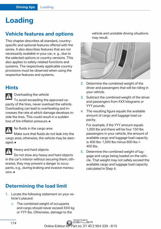
LoadingVehicle features and optionsThis chapter describes all standard, country-specific and optional features offered with theseries. It also describes features that are notnecessarily available in your car, e. g., due tothe selected options or country versions. Thisalso applies to safety-related functions andsystems. The respectively applicable countryprovisions must be observed when using therespective features and systems.
HintsOverloading the vehicleTo avoid exceeding the approved ca‐
pacity of the tires, never overload the vehicle.Overloading can lead to overheating and in‐creases the rate at which damage develops in‐side the tires. This could result in a suddenloss of tire inflation pressure.◀
No fluids in the cargo areaMake sure that fluids do not leak into the
cargo area; otherwise, the vehicle may be dam‐aged.◀
Heavy and hard objectsDo not stow any heavy and hard objects
in the car's interior without securing them; oth‐erwise, they may present a danger to occu‐pants, e.g., during braking and evasive maneu‐vers.◀
Determining the load limit1. Locate the following statement on your ve‐
hicle’s placard:▷ The combined weight of occupants
and cargo should never exceed XXX kgor YYY lbs. Otherwise, damage to the
vehicle and unstable driving situationsmay result.
2. Determine the combined weight of thedriver and passengers that will be riding inyour vehicle.
3. Subtract the combined weight of the driverand passengers from XXX kilograms orYYY pounds.
4. The resulting figure equals the availableamount of cargo and luggage load ca‐pacity.For example, if the YYY amount equals1,000 lbs and there will be four 150 lbspassengers in your vehicle, the amount ofavailable cargo and luggage load capacityis 400 lbs: 1,000 lbs minus 600 lbs =400 lbs.
5. Determine the combined weight of lug‐gage and cargo being loaded on the vehi‐cle. That weight may not safely exceed theavailable cargo and luggage load capacitycalculated in Step 4.
Seite 174
Driving tips Loading
174Online Edition for Part no. 01 40 2 954 339 - II/15
Information Provided by:
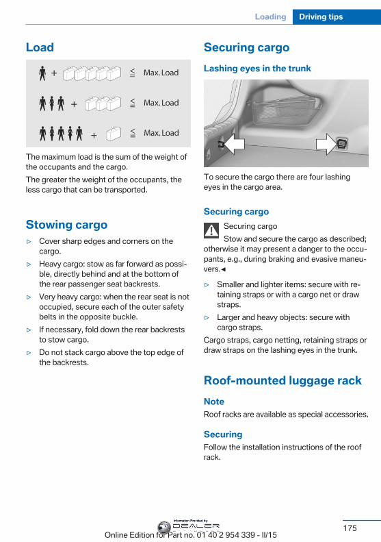
Load
The maximum load is the sum of the weight ofthe occupants and the cargo.The greater the weight of the occupants, theless cargo that can be transported.
Stowing cargo▷ Cover sharp edges and corners on the
cargo.▷ Heavy cargo: stow as far forward as possi‐
ble, directly behind and at the bottom ofthe rear passenger seat backrests.
▷ Very heavy cargo: when the rear seat is notoccupied, secure each of the outer safetybelts in the opposite buckle.
▷ If necessary, fold down the rear backreststo stow cargo.
▷ Do not stack cargo above the top edge ofthe backrests.
Securing cargoLashing eyes in the trunk
To secure the cargo there are four lashingeyes in the cargo area.
Securing cargoSecuring cargoStow and secure the cargo as described;
otherwise it may present a danger to the occu‐pants, e.g., during braking and evasive maneu‐vers.◀
▷ Smaller and lighter items: secure with re‐taining straps or with a cargo net or drawstraps.
▷ Larger and heavy objects: secure withcargo straps.
Cargo straps, cargo netting, retaining straps ordraw straps on the lashing eyes in the trunk.
Roof-mounted luggage rackNoteRoof racks are available as special accessories.
SecuringFollow the installation instructions of the roofrack.
Seite 175
Loading Driving tips
175Online Edition for Part no. 01 40 2 954 339 - II/15
Information Provided by:
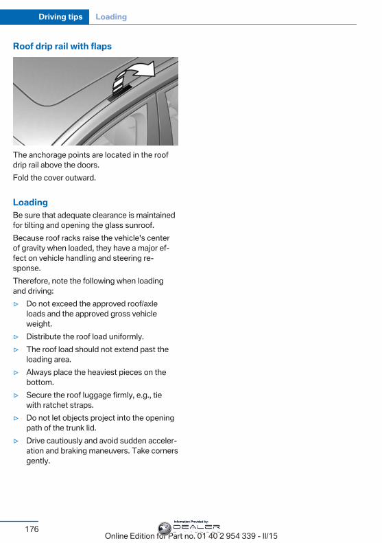
Roof drip rail with flaps
The anchorage points are located in the roofdrip rail above the doors.Fold the cover outward.
LoadingBe sure that adequate clearance is maintainedfor tilting and opening the glass sunroof.Because roof racks raise the vehicle's centerof gravity when loaded, they have a major ef‐fect on vehicle handling and steering re‐sponse.Therefore, note the following when loadingand driving:▷ Do not exceed the approved roof/axle
loads and the approved gross vehicleweight.
▷ Distribute the roof load uniformly.▷ The roof load should not extend past the
loading area.▷ Always place the heaviest pieces on the
bottom.▷ Secure the roof luggage firmly, e.g., tie
with ratchet straps.▷ Do not let objects project into the opening
path of the trunk lid.▷ Drive cautiously and avoid sudden acceler‐
ation and braking maneuvers. Take cornersgently.
Seite 176
Driving tips Loading
176Online Edition for Part no. 01 40 2 954 339 - II/15
Information Provided by:

Saving fuelVehicle features and optionsThis chapter describes all standard, country-specific and optional features offered with theseries. It also describes features that are notnecessarily available in your car, e. g., due tothe selected options or country versions. Thisalso applies to safety-related functions andsystems. The respectively applicable countryprovisions must be observed when using therespective features and systems.
General informationYour vehicle contains advanced technology forthe reduction of fuel consumption and emis‐sions.Fuel consumption depends on a number of dif‐ferent factors.Carrying out certain measures, such as a mod‐erate driving style and regular maintenance,can influence fuel consumption and the envi‐ronmental impact.
Remove unnecessary cargoAdditional weight increases fuel consumption.
Remove attached partsfollowing useRemove auxiliary mirrors, roof or rear luggageracks which are no longer required followinguse.Attached parts on the vehicle impair the aero‐dynamics and increase the fuel consumption.
Close the windows and glasssunroofDriving with the glass sunroof and windowsopen results in increased air resistance andthereby reduces the range.
TiresGeneral informationTires can affect fuel consumption in variousways, e.g., tire size may influence fuel con‐sumption.
Check the tire inflation pressureregularlyCheck and, if needed, correct the tire inflationpressure at least twice a month and beforestarting on a long trip.Low tire inflation pressure increases rolling re‐sistance and thus raises fuel consumption andtire wear.
Drive away immediatelyDo not wait for the engine to warm-up whilethe vehicle remains stationary. Start drivingright away, but at moderate engine speeds.This is the quickest way of warming the coldengine up to operating temperature.
Look well ahead whendrivingAvoid unnecessary acceleration and braking.By maintaining a suitable distance to the vehi‐cle driving ahead of you.Driving smoothly and proactively reduces fuelconsumption.
Seite 177
Saving fuel Driving tips
177Online Edition for Part no. 01 40 2 954 339 - II/15
Information Provided by:
Avoid high engine speedsAs a rule: driving at low engine speeds lowersfuel consumption and reduces wear.Use 1st gear to get the vehicle moving. Start‐ing with the 2nd gear, accelerate rapidly. Whenaccelerating, shift up before reaching high en‐gine speeds.When you reach the desired speed, shift intothe highest applicable gear and drive with theengine speed as low as possible and at a con‐stant speed.If necessary, observe the gear shift indicator ofthe vehicle, refer to page 91.
Use coastingWhen approaching a red light, take your footoff the accelerator and let the vehicle coast toa halt.For going downhill take your foot off the accel‐erator and let the vehicle roll.The flow of fuel is interrupted while coasting.
Switch off the engine duringlonger stopsSwitch off the engine during longer stops, e.g.,at traffic lights, railroad crossings or in trafficcongestion.
Auto Start/Stop functionThe Auto Start/Stop function of your vehicleautomatically switches off the engine during astop.If the engine is switched off and then restartedrather than leaving the engine running con‐stantly, fuel consumption and emissions arereduced. Savings can begin within a few sec‐onds of switching off the engine.In addition, fuel consumption is also deter‐mined by other factors, such as driving style,
road conditions, maintenance or environmentalfactors.
Switch off any functions thatare not currently neededFunctions such as seat heating and the rearwindow defroster require a lot of energy andreduce the range, especially in city and stop-and-go traffic.Reel off these functions if they are not needed.
Have maintenance carriedoutHave vehicles maintained regularly to achieveoptimal vehicle efficiency and operating life.The maintenance should be carried out byyour service center.Also note the BMW Maintenance System, referto page 201.
Seite 178
Driving tips Saving fuel
178Online Edition for Part no. 01 40 2 954 339 - II/15
Information Provided by:

Seite 179
Saving fuel Driving tips
179Online Edition for Part no. 01 40 2 954 339 - II/15
Information Provided by:
Online Edition for Part no. 01 40 2 954 339 - II/15
Information Provided by:
MobilityIn order to always ensure your mobility, you will
find important information on operating fluids,wheels and tires, maintenance and Roadside
Assistance in the following.
Online Edition for Part no. 01 40 2 954 339 - II/15
Information Provided by:
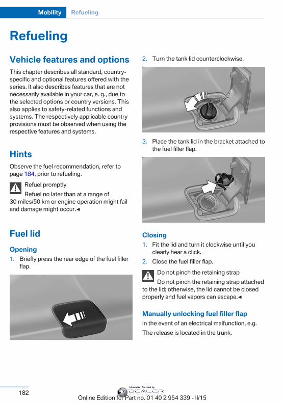
RefuelingVehicle features and optionsThis chapter describes all standard, country-specific and optional features offered with theseries. It also describes features that are notnecessarily available in your car, e. g., due tothe selected options or country versions. Thisalso applies to safety-related functions andsystems. The respectively applicable countryprovisions must be observed when using therespective features and systems.
HintsObserve the fuel recommendation, refer topage 184, prior to refueling.
Refuel promptlyRefuel no later than at a range of
30 miles/50 km or engine operation might failand damage might occur.◀
Fuel lidOpening1. Briefly press the rear edge of the fuel filler
flap.
2. Turn the tank lid counterclockwise.
3. Place the tank lid in the bracket attached tothe fuel filler flap.
Closing1. Fit the lid and turn it clockwise until you
clearly hear a click.2. Close the fuel filler flap.
Do not pinch the retaining strapDo not pinch the retaining strap attached
to the lid; otherwise, the lid cannot be closedproperly and fuel vapors can escape.◀
Manually unlocking fuel filler flapIn the event of an electrical malfunction, e.g.The release is located in the trunk.
Seite 182
Mobility Refueling
182Online Edition for Part no. 01 40 2 954 339 - II/15
Information Provided by:
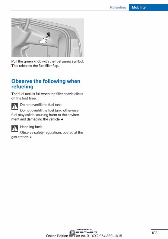
Pull the green knob with the fuel pump symbol.This releases the fuel filler flap.
Observe the following whenrefuelingThe fuel tank is full when the filler nozzle clicksoff the first time.
Do not overfill the fuel tankDo not overfill the fuel tank; otherwise
fuel may eslide, causing harm to the environ‐ment and damaging the vehicle.◀
Handling fuelsObserve safety regulations posted at the
gas station.◀
Seite 183
Refueling Mobility
183Online Edition for Part no. 01 40 2 954 339 - II/15
Information Provided by:
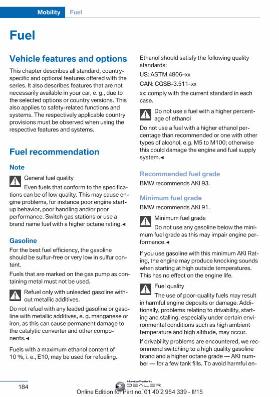
FuelVehicle features and optionsThis chapter describes all standard, country-specific and optional features offered with theseries. It also describes features that are notnecessarily available in your car, e. g., due tothe selected options or country versions. Thisalso applies to safety-related functions andsystems. The respectively applicable countryprovisions must be observed when using therespective features and systems.
Fuel recommendationNote
General fuel qualityEven fuels that conform to the specifica‐
tions can be of low quality. This may cause en‐gine problems, for instance poor engine start-up behavior, poor handling and/or poorperformance. Switch gas stations or use abrand name fuel with a higher octane rating.◀
GasolineFor the best fuel efficiency, the gasolineshould be sulfur-free or very low in sulfur con‐tent.Fuels that are marked on the gas pump as con‐taining metal must not be used.
Refuel only with unleaded gasoline with‐out metallic additives.
Do not refuel with any leaded gasoline or gaso‐line with metallic additives, e. g. manganese oriron, as this can cause permanent damage tothe catalytic converter and other compo‐nents.◀
Fuels with a maximum ethanol content of10 %, i. e., E10, may be used for refueling.
Ethanol should satisfy the following qualitystandards:US: ASTM 4806–xxCAN: CGSB-3.511–xxxx: comply with the current standard in eachcase.
Do not use a fuel with a higher percent‐age of ethanol
Do not use a fuel with a higher ethanol per‐centage than recommended or one with othertypes of alcohol, e.g. M5 to M100; otherwisethis could damage the engine and fuel supplysystem.◀
Recommended fuel gradeBMW recommends AKI 93.
Minimum fuel gradeBMW recommends AKI 91.
Minimum fuel gradeDo not use any gasoline below the mini‐
mum fuel grade as this may impair engine per‐formance.◀
If you use gasoline with this minimum AKI Rat‐ing, the engine may produce knocking soundswhen starting at high outside temperatures.This has no effect on the engine life.
Fuel qualityThe use of poor-quality fuels may result
in harmful engine deposits or damage. Addi‐tionally, problems relating to drivability, start‐ing and stalling, especially under certain envi‐ronmental conditions such as high ambienttemperature and high altitude, may occur.If drivability problems are encountered, we rec‐ommend switching to a high quality gasolinebrand and a higher octane grade — AKI num‐ber — for a few tank fills. To avoid harmful en‐
Seite 184
Mobility Fuel
184Online Edition for Part no. 01 40 2 954 339 - II/15
Information Provided by:
gine deposits, it is highly recommended topurchase gasoline from Top Tier retailers.Failure to comply with these recommendationsmay result in the need for unscheduled main‐tenance.◀
Seite 185
Fuel Mobility
185Online Edition for Part no. 01 40 2 954 339 - II/15
Information Provided by:
Wheels and tiresVehicle features and optionsThis chapter describes all standard, country-specific and optional features offered with theseries. It also describes features that are notnecessarily available in your car, e. g., due tothe selected options or country versions. Thisalso applies to safety-related functions andsystems. The respectively applicable countryprovisions must be observed when using therespective features and systems.
Tire inflation pressureSafety informationThe tire characteristics and tire inflation pres‐sure influence the following:▷ The service life of the tires.▷ Road safety.▷ Driving comfort.
Checking the tire inflation pressureCheck the tire inflation pressure regularlyRegularly check the tire inflation pres‐
sure, and correct it as needed: at least twice amonth and before a long trip. If you fail to ob‐serve this precaution, you may be driving ontires with incorrect tire pressures, a conditionthat may not only compromise your vehicle'sdriving stability, but also lead to tire damageand the risk of an accident.◀
Tires have a natural, consistent loss of tire in‐flation pressure.Tires heat up while driving, and the tire infla‐tion pressure increases along with the tire'stemperature. The tire inflation pressure speci‐fications relate to cold tires or tires with theambient temperature.
Only check the tire inflation pressure when thetires are cold. This means after driving no morethan 1.25 miles/2 km or when the vehicle hasbeen parked for at least 2 hours.The displays of inflation devices may under-read by up to 1.45 psi/0.1 bar.For Flat Tire Monitor: after correcting the tireinflation pressure, reinitialize the Flat TireMonitor.For Tire Pressure Monitor: after correcting thetire inflation pressure, reset the Tire PressureMonitor.
Tire inflation pressure specificationsThe tire inflation pressure table, refer topage 187, contains all tire inflation pressurespecifications for the specified tire sizes at theambient temperature. Tire inflation pressurespecifications apply to approved tire sizes andrecommended tire brands. This informationcan be obtained from your service center.To identify the correct tire inflation pressure,please note the following:▷ Tire sizes of your vehicle.▷ Maximum permitted driving speed.
Tire inflation pressures up to100 mph/160 km/hFor speeds of up to 100 mph/160 km/h and foroptimum driving comfort, note the pressurevalues in the tire inflation pressure table, referto page 187, and adjust as necessary.
Seite 186
Mobility Wheels and tires
186Online Edition for Part no. 01 40 2 954 339 - II/15
Information Provided by:
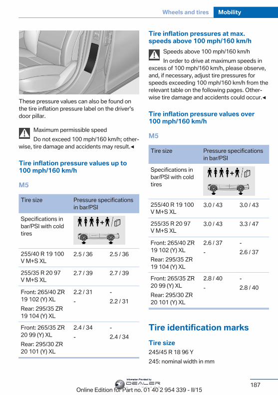
These pressure values can also be found onthe tire inflation pressure label on the driver'sdoor pillar.
Maximum permissible speedDo not exceed 100 mph/160 km/h; other‐
wise, tire damage and accidents may result.◀
Tire inflation pressure values up to100 mph/160 km/h
M5
Tire size Pressure specificationsin bar/PSI
Specifications inbar/PSI with coldtires
255/40 R 19 100 V M+S XL
2.5 / 36 2.5 / 36
255/35 R 20 97 V M+S XL
2.7 / 39 2.7 / 39
Front: 265/40 ZR19 102 (Y) XLRear: 295/35 ZR19 104 (Y) XL
2.2 / 31-
-2.2 / 31
Front: 265/35 ZR20 99 (Y) XLRear: 295/30 ZR20 101 (Y) XL
2.4 / 34-
-2.4 / 34
Tire inflation pressures at max.speeds above 100 mph/160 km/h
Speeds above 100 mph/160 km/hIn order to drive at maximum speeds in
excess of 100 mph/160 km/h, please observe,and, if necessary, adjust tire pressures forspeeds exceeding 100 mph/160 km/h from therelevant table on the following pages. Other‐wise tire damage and accidents could occur.◀
Tire inflation pressure values over100 mph/160 km/h
M5
Tire size Pressure specificationsin bar/PSI
Specifications inbar/PSI with coldtires
255/40 R 19 100 V M+S XL
3.0 / 43 3.0 / 43
255/35 R 20 97 V M+S XL
3.0 / 43 3.3 / 47
Front: 265/40 ZR19 102 (Y) XLRear: 295/35 ZR19 104 (Y) XL
2.6 / 37-
-2.6 / 37
Front: 265/35 ZR20 99 (Y) XLRear: 295/30 ZR20 101 (Y) XL
2.8 / 40-
-2.8 / 40
Tire identification marksTire size245/45 R 18 96 Y245: nominal width in mm
Seite 187
Wheels and tires Mobility
187Online Edition for Part no. 01 40 2 954 339 - II/15
Information Provided by:
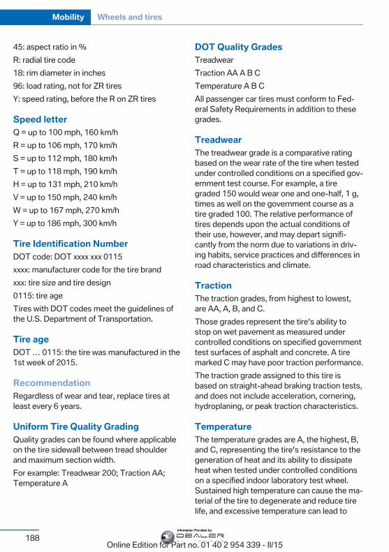
45: aspect ratio in %R: radial tire code18: rim diameter in inches96: load rating, not for ZR tiresY: speed rating, before the R on ZR tires
Speed letterQ = up to 100 mph, 160 km/hR = up to 106 mph, 170 km/hS = up to 112 mph, 180 km/hT = up to 118 mph, 190 km/hH = up to 131 mph, 210 km/hV = up to 150 mph, 240 km/hW = up to 167 mph, 270 km/hY = up to 186 mph, 300 km/h
Tire Identification NumberDOT code: DOT xxxx xxx 0115xxxx: manufacturer code for the tire brandxxx: tire size and tire design0115: tire ageTires with DOT codes meet the guidelines ofthe U.S. Department of Transportation.
Tire ageDOT … 0115: the tire was manufactured in the1st week of 2015.
RecommendationRegardless of wear and tear, replace tires atleast every 6 years.
Uniform Tire Quality GradingQuality grades can be found where applicableon the tire sidewall between tread shoulderand maximum section width.For example: Treadwear 200; Traction AA;Temperature A
DOT Quality GradesTreadwearTraction AA A B CTemperature A B CAll passenger car tires must conform to Fed‐eral Safety Requirements in addition to thesegrades.
TreadwearThe treadwear grade is a comparative ratingbased on the wear rate of the tire when testedunder controlled conditions on a specified gov‐ernment test course. For example, a tiregraded 150 would wear one and one-half, 1 g,times as well on the government course as atire graded 100. The relative performance oftires depends upon the actual conditions oftheir use, however, and may depart signifi‐cantly from the norm due to variations in driv‐ing habits, service practices and differences inroad characteristics and climate.
TractionThe traction grades, from highest to lowest,are AA, A, B, and C.Those grades represent the tire's ability tostop on wet pavement as measured undercontrolled conditions on specified governmenttest surfaces of asphalt and concrete. A tiremarked C may have poor traction performance.The traction grade assigned to this tire isbased on straight-ahead braking traction tests,and does not include acceleration, cornering,hydroplaning, or peak traction characteristics.
TemperatureThe temperature grades are A, the highest, B,and C, representing the tire's resistance to thegeneration of heat and its ability to dissipateheat when tested under controlled conditionson a specified indoor laboratory test wheel.Sustained high temperature can cause the ma‐terial of the tire to degenerate and reduce tirelife, and excessive temperature can lead to
Seite 188
Mobility Wheels and tires
188Online Edition for Part no. 01 40 2 954 339 - II/15
Information Provided by:

sudden tire failure. The grade C correspondsto a level of performance which all passengercar tires must meet under the Federal MotorVehicle Safety Standard No. 109. Grades BandA represent higher levels of performance onthe laboratory test wheel than the minimum re‐quired by law.
Temperature grade for this tireThe temperature grade for this tire is es‐
tablished for a tire that is properly inflated andnot overloaded. Excessive speed, underinfla‐tion, or excessive loading, either separately orin combination, can cause heat buildup andpossible tire failure.If necessary, have the vehicle towed.◀
M+SWinter and all-season tires with better coldweather performance than summer tires.
Tire treadSummer tiresDo not drive with a tire tread depth of less than0.12 in/3 mm.There is an increased danger of hydroplaning ifthe tire tread depth is less than 0.12 in/3 mm.
Winter tiresDo not drive with a tire tread depth of less than0.16 in/4 mm.Below a tread depth of 0.16 in/4 mm, tires areless suitable for winter operation.
Minimum tread depth
Wear indicators are distributed around thetire's circumference and have the legally re‐quired minimum height of 0.063 in/1.6 mm.
They are marked on the side of the tire withTWI, Tread Wear Indicator.
Tire damageGeneral informationInspect your tires often for damage, foreignobjects lodged in the tread, and tread wear.
HintsDriving over rough or damaged road surfaces,as well as debris, curbs and other obstaclescan cause serious damage to wheels, tires andsuspension parts. This is more likely to occurwith low-profile tires, which provide less cush‐ioning between the wheel and the road. Becareful to avoid road hazards and reduce yourspeed, especially if your vehicle is equippedwith low-profile tires.Indications of tire damage or other vehicle de‐fects:▷ Unusual vibrations while driving.▷ Unusual handling such as a strong ten‐
dency to pull to the left or right.Damage can, e. g., be caused by driving overcurbs, road damage, or similar things.
Seite 189
Wheels and tires Mobility
189Online Edition for Part no. 01 40 2 954 339 - II/15
Information Provided by:
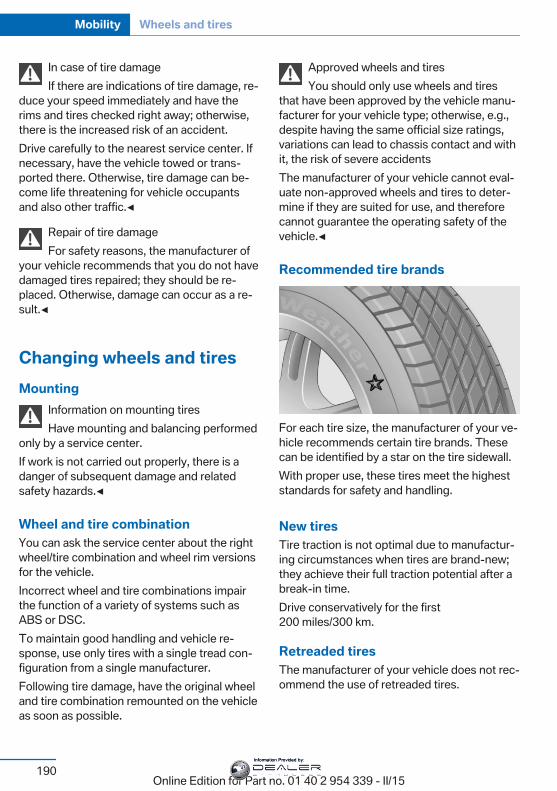
In case of tire damageIf there are indications of tire damage, re‐
duce your speed immediately and have therims and tires checked right away; otherwise,there is the increased risk of an accident.Drive carefully to the nearest service center. Ifnecessary, have the vehicle towed or trans‐ported there. Otherwise, tire damage can be‐come life threatening for vehicle occupantsand also other traffic.◀
Repair of tire damageFor safety reasons, the manufacturer of
your vehicle recommends that you do not havedamaged tires repaired; they should be re‐placed. Otherwise, damage can occur as a re‐sult.◀
Changing wheels and tiresMounting
Information on mounting tiresHave mounting and balancing performed
only by a service center.If work is not carried out properly, there is adanger of subsequent damage and relatedsafety hazards.◀
Wheel and tire combinationYou can ask the service center about the rightwheel/tire combination and wheel rim versionsfor the vehicle.Incorrect wheel and tire combinations impairthe function of a variety of systems such asABS or DSC.To maintain good handling and vehicle re‐sponse, use only tires with a single tread con‐figuration from a single manufacturer.Following tire damage, have the original wheeland tire combination remounted on the vehicleas soon as possible.
Approved wheels and tiresYou should only use wheels and tires
that have been approved by the vehicle manu‐facturer for your vehicle type; otherwise, e.g.,despite having the same official size ratings,variations can lead to chassis contact and withit, the risk of severe accidentsThe manufacturer of your vehicle cannot eval‐uate non-approved wheels and tires to deter‐mine if they are suited for use, and thereforecannot guarantee the operating safety of thevehicle.◀
Recommended tire brands
For each tire size, the manufacturer of your ve‐hicle recommends certain tire brands. Thesecan be identified by a star on the tire sidewall.With proper use, these tires meet the higheststandards for safety and handling.
New tiresTire traction is not optimal due to manufactur‐ing circumstances when tires are brand-new;they achieve their full traction potential after abreak-in time.Drive conservatively for the first200 miles/300 km.
Retreaded tiresThe manufacturer of your vehicle does not rec‐ommend the use of retreaded tires.
Seite 190
Mobility Wheels and tires
190Online Edition for Part no. 01 40 2 954 339 - II/15
Information Provided by:
Retreaded tiresPossibly substantial variations in the de‐
sign and age of the tire casing structures canlimit service life and have a negative impact onroad safety.◀
Winter tiresWinter tires are recommended for operating onwinter roads.Although so-called all-season M+S tires pro‐vide better winter traction than summer tires,they do not provide the same level of perform‐ance as winter tires.
Maximum speed of winter tiresIf the maximum speed of the vehicle is higherthan the permissible speed for the winter tires,then a respective symbol is displayed in yourfield of vision. You can obtain this sign from thetire specialist or from your service center.
Maximum speed for winter tiresDo not exceed the maximum speed for
the respective winter tires; otherwise, tire dam‐age and accidents can occur.◀
Rotating wheels between axlesThe manufacturer of your vehicle advisesagainst switching wheels between the frontand rear axles. This can impair the handlingcharacteristics.Rotating the tires is not permissible on vehi‐cles with different tire sizes or rim sizes on thefront and rear axles.
StorageStore wheels and tires in a cool, dry place withas little exposure to light as possible.Always protect tires against all contact with oil,grease and fuels.Do not exceed the maximum tire inflation pres‐sure indicated on the side wall of the tire.
Mobility SystemThe conceptWith the Mobility System, minor tire damagecan be sealed quickly to enable continuedtravel. To accomplish this, sealant is pumpedinto the tires, which seals the damage from theinside.The compressor can be used to check the tireinflation pressure.
Hints▷ Follow the instructions on using the Mobi‐
lity System found on the compressor andsealant container.
▷ Use of the Mobility System may be ineffec‐tive if the tire puncture measures approx.1/8 in/4 mm or more.
▷ Contact the nearest service center if thetire cannot be made drivable.
▷ If possible, do not remove foreign bodiesthat have penetrated the tire.
▷ Pull the speed limit sticker off the sealantcontainer and apply it to the steeringwheel.
▷ The use of a sealant can damage the TPMwheel electronics. In this case, have theelectronics checked at the next opportu‐nity and have them replaced if needed.
Enclosed areasDo not let the engine run in enclosed
areas, since breathing in exhaust fumes maylead to loss of consciousness and death. Theexhaust gases contain carbon monoxide, anodorless and colorless but highly toxic gas.◀
StorageThe Mobility System is located under thecargo floor panel.
Seite 191
Wheels and tires Mobility
191Online Edition for Part no. 01 40 2 954 339 - II/15
Information Provided by:
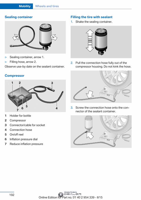
Sealing container
▷ Sealing container, arrow 1.▷ Filling hose, arrow 2.Observe use-by date on the sealant container.
Compressor
1 Holder for bottle2 Compressor3 Connector/cable for socket4 Connection hose5 On/off reel6 Inflation pressure dial7 Reduce inflation pressure
Filling the tire with sealant1. Shake the sealing container.
2. Pull the connection hose fully out of thecompressor housing. Do not kink the hose.
3. Screw the connection hose onto the con‐nector of the sealant container.
Seite 192
Mobility Wheels and tires
192Online Edition for Part no. 01 40 2 954 339 - II/15
Information Provided by:
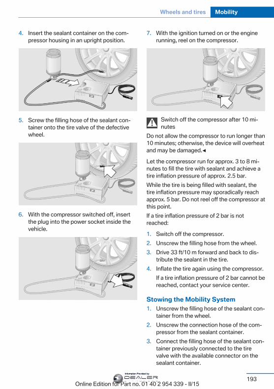
4. Insert the sealant container on the com‐pressor housing in an upright position.
5. Screw the filling hose of the sealant con‐tainer onto the tire valve of the defectivewheel.
6. With the compressor switched off, insertthe plug into the power socket inside thevehicle.
7. With the ignition turned on or the enginerunning, reel on the compressor.
Switch off the compressor after 10 mi‐nutes
Do not allow the compressor to run longer than10 minutes; otherwise, the device will overheatand may be damaged.◀
Let the compressor run for approx. 3 to 8 mi‐nutes to fill the tire with sealant and achieve atire inflation pressure of approx. 2.5 bar.While the tire is being filled with sealant, thetire inflation pressure may sporadically reachapprox. 5 bar. Do not reel off the compressor atthis point.If a tire inflation pressure of 2 bar is notreached:
1. Switch off the compressor.2. Unscrew the filling hose from the wheel.3. Drive 33 ft/10 m forward and back to dis‐
tribute the sealant in the tire.4. Inflate the tire again using the compressor.
If a tire inflation pressure of 2 bar cannot bereached, contact your service center.
Stowing the Mobility System1. Unscrew the filling hose of the sealant con‐
tainer from the wheel.2. Unscrew the connection hose of the com‐
pressor from the sealant container.3. Connect the filling hose of the sealant con‐
tainer previously connected to the tirevalve with the available connector on thesealant container.
Seite 193
Wheels and tires Mobility
193Online Edition for Part no. 01 40 2 954 339 - II/15
Information Provided by:
This prevents leftover sealant from escap‐ing from the container.
4. Wrap the empty sealant container in suita‐ble material to avoid dirtying the cargoarea.
5. Stow the Mobility System back in the vehi‐cle.
Distributing the sealantImmediately drive approx. 5 miles/10 km to en‐sure that the sealant is evenly distributed in thetire.Do not exceed a speed of 50 mph/80 km/h.If possible, do not drive at speeds less than12 mph/20 km/h.
To correct the tire inflation pressure1. Stop at a suitable location.2. Screw the connection hose of the com‐
pressor directly onto the tire valve stem.3. Insert the connector into the power socket
inside the vehicle.4. Correct the tire inflation pressure to
2.5 bar.▷ Increase pressure: with the ignition
turned on or the engine running, reelon the compressor.
▷ To reduce the pressure: press the but‐ton on the compressor.
Continuing the tripDo not exceed the maximum permissiblespeed of 50 mph/80 km/h.Reinitialize the Flat Tire Monitor.Reinitialize the Tire Pressure Monitor.Replace the defective tire and the sealant con‐tainer of the Mobility System as soon as possi‐ble.
Snow chainsFine-link snow chainsOnly certain types of fine-link snow chainshave been tested by the manufacturer of thevehicle, classified as road-safe and approved.Information about the approved snow chainsare available from the service center.
UseUse only in pairs on the rear wheels, equippedwith the tires of the following size:▷ 255/40 R 19▷ 255/35 R 20Follow the snow chain manufacturer's instruc‐tions.Make sure that the snow chains are alwayssufficiently tight. Retighten as needed accord‐ing to the chain manufacturer's instructions.Do not initialize the Flat Tire Monitor aftermounting snow chains, as doing so may resultin incorrect readings.Do not initialize the Tire Pressure Monitor aftermounting snow chains, as doing so may resultin incorrect readings.When driving with snow chains, if neededbriefly activate M Dynamic Mode.
Maximum speed with snow chainsDo not exceed a speed of 30 mph/50 km/hwhen using snow chains.
Seite 194
Mobility Wheels and tires
194Online Edition for Part no. 01 40 2 954 339 - II/15
Information Provided by:

Engine compartmentVehicle features and optionsThis chapter describes all standard, country-specific and optional features offered with theseries. It also describes features that are notnecessarily available in your car, e. g., due to
the selected options or country versions. Thisalso applies to safety-related functions andsystems. The respectively applicable countryprovisions must be observed when using therespective features and systems.
Important features in the engine compartment
1 Vehicle identification number2 Jump-starting, negative battery terminal3 Washer fluid reservoir4 Jump-starting, positive battery terminal
5 Coolant reservoir for charge air cooling6 Oil filler neck.7 Coolant reservoir for engine cooling
HoodOpening the hood
Working in the engine compartmentNever attempt to perform any service or
repair operations on your vehicle without thenecessary professional technical training.
If you are unfamiliar with the statutory guide‐lines, have any work on the vehicle performedonly by a service center.If work is not carried out properly, there is adanger of subsequent damage and relatedsafety hazards.◀
Seite 195
Engine compartment Mobility
195Online Edition for Part no. 01 40 2 954 339 - II/15
Information Provided by:
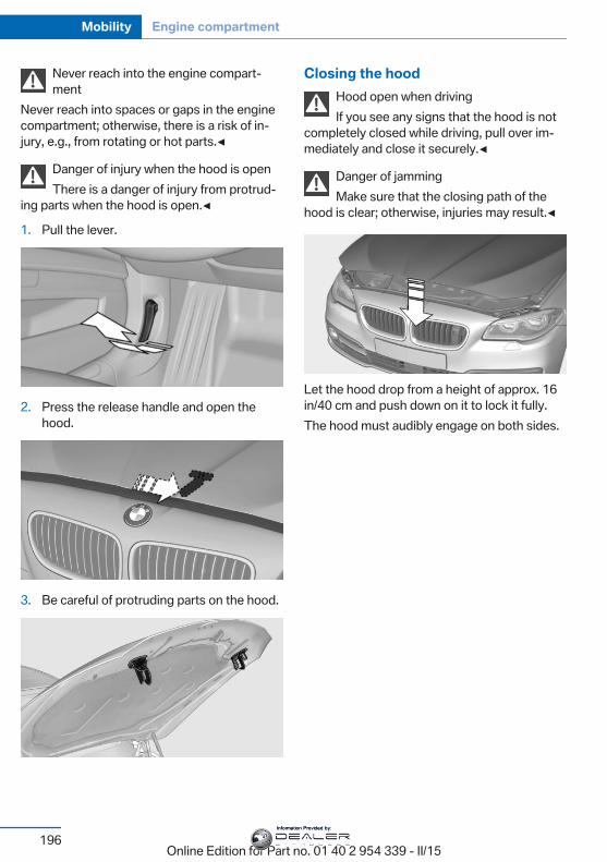
Never reach into the engine compart‐ment
Never reach into spaces or gaps in the enginecompartment; otherwise, there is a risk of in‐jury, e.g., from rotating or hot parts.◀
Danger of injury when the hood is openThere is a danger of injury from protrud‐
ing parts when the hood is open.◀
1. Pull the lever.
2. Press the release handle and open thehood.
3. Be careful of protruding parts on the hood.
Closing the hoodHood open when drivingIf you see any signs that the hood is not
completely closed while driving, pull over im‐mediately and close it securely.◀
Danger of jammingMake sure that the closing path of the
hood is clear; otherwise, injuries may result.◀
Let the hood drop from a height of approx. 16in/40 cm and push down on it to lock it fully.The hood must audibly engage on both sides.
Seite 196
Mobility Engine compartment
196Online Edition for Part no. 01 40 2 954 339 - II/15
Information Provided by:
Engine oilVehicle features and optionsThis chapter describes all standard, country-specific and optional features offered with theseries. It also describes features that are notnecessarily available in your car, e. g., due tothe selected options or country versions. Thisalso applies to safety-related functions andsystems. The respectively applicable countryprovisions must be observed when using therespective features and systems.
General informationThe engine oil consumption is dependent onthe driving style and driving conditions.The engine oil consumption can increase incase of, for example:▷ Sporty driving.▷ Break-in the engine.▷ Idling of the engine.▷ Usage of non-approved engine oil grades.Therefore, regularly check the engine oil levelafter refueling.When a dynamic driving style is used, such aswhen cornering fast, the system is unable tomeasure the engine oil level. With this drivingstyle, measure the engine oil level using a de‐tailed measurement, refer to page 198.Depending on its engine, the vehicle is equip‐ped with electronic oil measurement or oilmeasuring is done with a dipstick.The electronic oil measurement has two meas‐uring principles:▷ Status display▷ Detailed measurement
Electronic oil measurementStatus display
The conceptThe engine oil level is monitored electronicallywhile driving and shown on the Control Dis‐play.If the engine oil level reaches the minimumlevel, a check control message is displayed.
RequirementsA current measured value is available after ap‐prox. 30 minutes of driving. During a shortertrip, the status of the last, sufficiently long tripis displayed.With frequent short-distance trips, regularlyperform a detailed measurement.
Displaying the engine oil levelOn the Control Display:
1. "Vehicle info"2. "Vehicle status"3. "Engine oil level"
Engine oil level display messagesDifferent messages appear on the display de‐pending on the engine oil level. Pay attentionto these messages.If the engine oil level is too low, within the next125 miles/200 km Add engine oil, refer topage 198.
Engine oil level too lowAdd engine oil immediately; otherwise,
an insufficient amount of engine oil could re‐sult in engine damage.◀
Take care not to add too much engine oil.
Seite 197
Engine oil Mobility
197Online Edition for Part no. 01 40 2 954 339 - II/15
Information Provided by:

Too much engine oilHave the vehicle checked immediately;
otherwise, surplus engine oil can lead to en‐gine damage.◀
Detailed measurement
The conceptIn the detailed measurement the engine oillevel is checked and displayed via a scale.Gasoline engine:If the engine oil level reaches the minimumlevel, a check control message is displayed.Diesel engine:During the measurement, the idle speed is in‐creased somewhat.
Requirements▷ Vehicle is on level road.▷ Manual transmission: shift lever in neutral
position, clutch and accelerator pedals notdepressed.
▷ M Double clutch transmission: selectorlever in selector lever position N and accel‐erator pedal not depressed.
▷ Engine is running and is at operating tem‐perature.
Performing a detailed measurementIn order to perform a detailed measurement ofthe engine oil level:
1. "Vehicle info"2. "Vehicle status"3. "Measure engine oil level"4. "Start measurement"The engine oil level is checked and displayedvia a scale.Time: approx. 1 minute.
Adding engine oilGeneral informationSwitch off the ignition and safely park the vehi‐cle before engine oil is added.
Oil filler neck
Only add engine oil when the message is dis‐played in the instrument cluster. The quantityto be added is indicated in the message dis‐played in the instrument cluster.
Adding engine oilAdd oil within the next 125 miles/200 km;
otherwise, this may cause engine damage.◀
Do not add too much engine oilWhen too much engine oil is added, im‐
mediately have the vehicle checked, otherwise,this may cause engine damage.◀
Protect childrenKeep oil, grease, etc., out of reach of chil‐
dren and observe the warnings on the contain‐ers to prevent health risks.◀
Engine oil types to addHints
No oil additivesOil additives may lead to engine dam‐
age.◀
Seite 198
Mobility Engine oil
198Online Edition for Part no. 01 40 2 954 339 - II/15
Information Provided by:
Viscosity grades for engine oilsWhen selecting an engine oil, ensure that
the engine oil belongs to the viscosity gradeSAE 0W-40, or malfunctions or engine dam‐age may occur.As an alternative, you can also use motor oilswith a viscosity grade of SAE 0W-30.◀
The engine oil quality is critical for the life ofthe engine.
Suitable engine oil typesYou can add engine oils that meet the follow‐ing oil rating standards:
Oil rating
BMW Longlife-01.
BMW Longlife-01 FE.
Further information regarding the oil specifica‐tions and viscosities of engine oils can be in‐quired with the service center.
Alternative engine oil typesIf an engine oil suitable for continuous use isnot available, up to 1 US quart/liter of an en‐gine oil with the following oil rating can beadded:
Oil rating
API SM or superior oil rating.
Engine oil change:The vehicle manufacturer recommends thatyou let the service center change the motor oil.
Seite 199
Engine oil Mobility
199Online Edition for Part no. 01 40 2 954 339 - II/15
Information Provided by:
CoolantVehicle features and optionsThis chapter describes all standard, country-specific and optional features offered with theseries. It also describes features that are notnecessarily available in your car, e. g., due tothe selected options or country versions. Thisalso applies to safety-related functions andsystems. The respectively applicable countryprovisions must be observed when using therespective features and systems.
HintsDanger of burns from hot engineDo not open the cooling system while
the engine is hot; otherwise, esliding coolantmay cause burns.◀
Suitable additivesOnly use suitable additives; otherwise,
engine damage may occur. The additives areharmful to your health.◀
Coolant consists of water and additives.Not all commercially available additives aresuitable for the vehicle. Information about thesuitable additives are available from the servicecenter.
Coolant levelGeneral informationHave your service center check the coolantlevel and add coolant if needed.
DisposalComply with the relevant environmen‐tal protection regulations when dispos‐ing of coolant and coolant additives.
Seite 200
Mobility Coolant
200Online Edition for Part no. 01 40 2 954 339 - II/15
Information Provided by:
MaintenanceVehicle features and optionsThis chapter describes all standard, country-specific and optional features offered with theseries. It also describes features that are notnecessarily available in your car, e. g., due tothe selected options or country versions. Thisalso applies to safety-related functions andsystems. The respectively applicable countryprovisions must be observed when using therespective features and systems.
BMW maintenance systemThe maintenance system indicates requiredmaintenance measures, and thereby providessupport in maintaining road safety and the op‐erational reliability of the vehicle.In some cases scopes and intervals may varyaccording to the country-specific version. Re‐placement work, spare parts, fuels and lubri‐cants and wear materials are calculated sepa‐rately. Additional information is available fromthe service center.
Condition Based ServiceCBSSensors and special algorithms take into ac‐count the driving conditions of your vehicle.Based on this, Condition Based Service recog‐nizes the maintenance requirements.The system makes it possible to adapt theamount of maintenance corresponding to youruser profile.Detailed information on service requirements,refer to page 90, can be displayed on the Con‐trol Display.
Service data in the remote controlInformation on the required maintenance iscontinuously stored in the remote control.Your service center will read out this data andsuggest the right array of service proceduresfor your vehicle.Therefore, hand your service specialist the re‐mote control with which the vehicle was drivenmost recently.
Storage periodsStorage periods during which the vehicle bat‐tery was disconnected are not taken into ac‐count.If this occurs, have a service center update thetime-dependent maintenance procedures,such as checking brake fluid and, if needed,changing the engine oil and the microfilter/activated-charcoal filter.
Service and WarrantyInformation Booklet for USmodels and Warranty andService Guide Booklet forCanadian modelsPlease consult your Service and Warranty In‐formation Booklet for US models and Warrantyand Service Guide Booklet for Canadian mod‐els for additional information on service re‐quirements.Maintenance and repair should be performedby your service center. Make sure to have reg‐ular maintenance procedures recorded in thevehicle's Service and Warranty InformationBooklet for US models, and in the Warrantyand Service Guide Booklet for Canadian mod‐els. These entries are proof of regular mainte‐nance.
Seite 201
Maintenance Mobility
201Online Edition for Part no. 01 40 2 954 339 - II/15
Information Provided by:
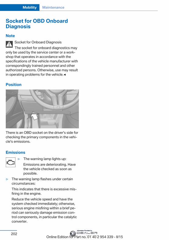
Socket for OBD OnboardDiagnosisNote
Socket for Onboard DiagnosisThe socket for onboard diagnostics may
only be used by the service center or a work‐shop that operates in accordance with thespecifications of the vehicle manufacturer withcorrespondingly trained personnel and otherauthorized persons. Otherwise, use may resultin operating problems for the vehicle.◀
Position
There is an OBD socket on the driver's side forchecking the primary components in the vehi‐cle's emissions.
Emissions▷ The warning lamp lights up:
Emissions are deteriorating. Havethe vehicle checked as soon aspossible.
▷ The warning lamp flashes under certaincircumstances:This indicates that there is excessive mis‐firing in the engine.Reduce the vehicle speed and have thesystem checked immediately; otherwise,serious engine misfiring within a brief pe‐riod can seriously damage emission con‐trol components, in particular the catalyticconverter.
Seite 202
Mobility Maintenance
202Online Edition for Part no. 01 40 2 954 339 - II/15
Information Provided by:
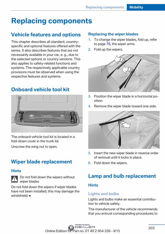
Replacing componentsVehicle features and optionsThis chapter describes all standard, country-specific and optional features offered with theseries. It also describes features that are notnecessarily available in your car, e. g., due tothe selected options or country versions. Thisalso applies to safety-related functions andsystems. The respectively applicable countryprovisions must be observed when using therespective features and systems.
Onboard vehicle tool kit
The onboard vehicle tool kit is located in afold-down cover in the trunk lid.Unscrew the wing nut to open.
Wiper blade replacementHints
Do not fold down the wipers withoutwiper blades
Do not fold down the wipers if wiper bladeshave not been installed; this may damage thewindshield.◀
Replacing the wiper blades1. To change the wiper blades, fold up, refer
to page 76, the wiper arms.2. Fold up the wipers.
3. Position the wiper blade in a horizontal po‐sition.
4. Remove the wiper blade toward one side.
5. Insert the new wiper blade in reverse orderof removal until it locks in place.
6. Fold down the wipers.
Lamp and bulb replacementHints
Lights and bulbsLights and bulbs make an essential contribu‐tion to vehicle safety.The manufacturer of the vehicle recommendsthat you entrust corresponding procedures to
Seite 203
Replacing components Mobility
203Online Edition for Part no. 01 40 2 954 339 - II/15
Information Provided by:
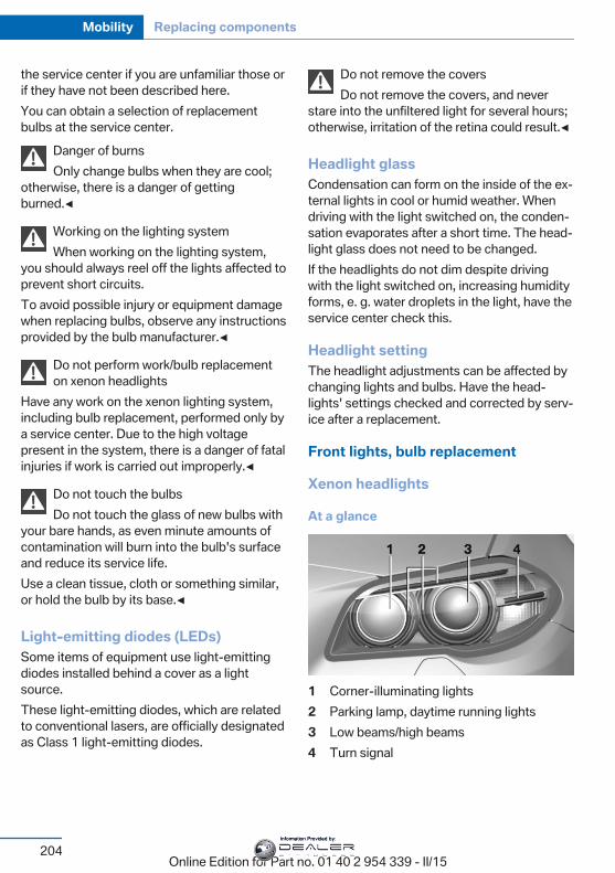
the service center if you are unfamiliar those orif they have not been described here.You can obtain a selection of replacementbulbs at the service center.
Danger of burnsOnly change bulbs when they are cool;
otherwise, there is a danger of gettingburned.◀
Working on the lighting systemWhen working on the lighting system,
you should always reel off the lights affected toprevent short circuits.To avoid possible injury or equipment damagewhen replacing bulbs, observe any instructionsprovided by the bulb manufacturer.◀
Do not perform work/bulb replacementon xenon headlights
Have any work on the xenon lighting system,including bulb replacement, performed only bya service center. Due to the high voltagepresent in the system, there is a danger of fatalinjuries if work is carried out improperly.◀
Do not touch the bulbsDo not touch the glass of new bulbs with
your bare hands, as even minute amounts ofcontamination will burn into the bulb's surfaceand reduce its service life.Use a clean tissue, cloth or something similar,or hold the bulb by its base.◀
Light-emitting diodes (LEDs)Some items of equipment use light-emittingdiodes installed behind a cover as a lightsource.These light-emitting diodes, which are relatedto conventional lasers, are officially designatedas Class 1 light-emitting diodes.
Do not remove the coversDo not remove the covers, and never
stare into the unfiltered light for several hours;otherwise, irritation of the retina could result.◀
Headlight glassCondensation can form on the inside of the ex‐ternal lights in cool or humid weather. Whendriving with the light switched on, the conden‐sation evaporates after a short time. The head‐light glass does not need to be changed.If the headlights do not dim despite drivingwith the light switched on, increasing humidityforms, e. g. water droplets in the light, have theservice center check this.
Headlight settingThe headlight adjustments can be affected bychanging lights and bulbs. Have the head‐lights' settings checked and corrected by serv‐ice after a replacement.
Front lights, bulb replacement
Xenon headlights
At a glance
1 Corner-illuminating lights2 Parking lamp, daytime running lights3 Low beams/high beams4 Turn signal
Seite 204
Mobility Replacing components
204Online Edition for Part no. 01 40 2 954 339 - II/15
Information Provided by:
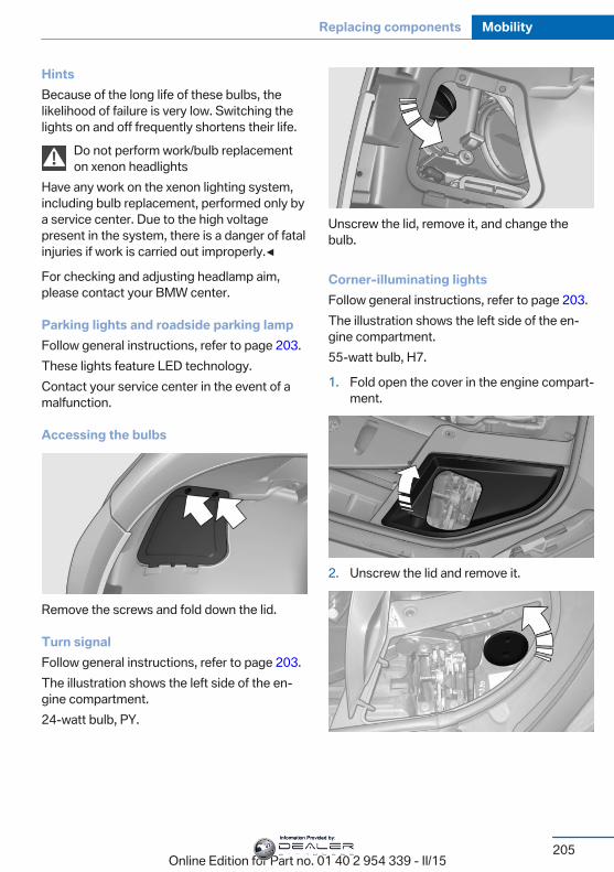
HintsBecause of the long life of these bulbs, thelikelihood of failure is very low. Switching thelights on and off frequently shortens their life.
Do not perform work/bulb replacementon xenon headlights
Have any work on the xenon lighting system,including bulb replacement, performed only bya service center. Due to the high voltagepresent in the system, there is a danger of fatalinjuries if work is carried out improperly.◀
For checking and adjusting headlamp aim,please contact your BMW center.
Parking lights and roadside parking lampFollow general instructions, refer to page 203.These lights feature LED technology.Contact your service center in the event of amalfunction.
Accessing the bulbs
Remove the screws and fold down the lid.
Turn signalFollow general instructions, refer to page 203.The illustration shows the left side of the en‐gine compartment.24-watt bulb, PY.
Unscrew the lid, remove it, and change thebulb.
Corner-illuminating lightsFollow general instructions, refer to page 203.The illustration shows the left side of the en‐gine compartment.55-watt bulb, H7.
1. Fold open the cover in the engine compart‐ment.
2. Unscrew the lid and remove it.
Seite 205
Replacing components Mobility
205Online Edition for Part no. 01 40 2 954 339 - II/15
Information Provided by:
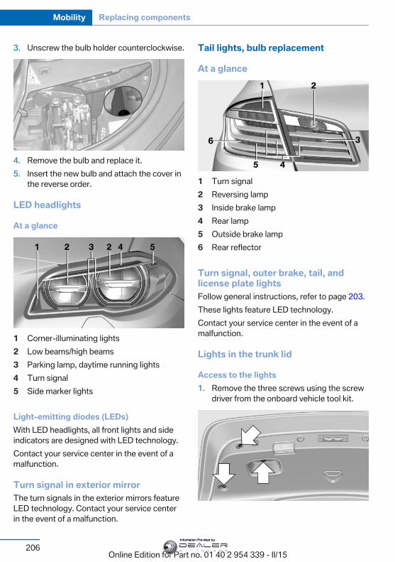
3. Unscrew the bulb holder counterclockwise.
4. Remove the bulb and replace it.5. Insert the new bulb and attach the cover in
the reverse order.
LED headlights
At a glance
1 Corner-illuminating lights2 Low beams/high beams3 Parking lamp, daytime running lights4 Turn signal5 Side marker lights
Light-emitting diodes (LEDs)With LED headlights, all front lights and sideindicators are designed with LED technology.Contact your service center in the event of amalfunction.
Turn signal in exterior mirrorThe turn signals in the exterior mirrors featureLED technology. Contact your service centerin the event of a malfunction.
Tail lights, bulb replacement
At a glance
1 Turn signal2 Reversing lamp3 Inside brake lamp4 Rear lamp5 Outside brake lamp6 Rear reflector
Turn signal, outer brake, tail, andlicense plate lightsFollow general instructions, refer to page 203.These lights feature LED technology.Contact your service center in the event of amalfunction.
Lights in the trunk lid
Access to the lights1. Remove the three screws using the screw
driver from the onboard vehicle tool kit.
Seite 206
Mobility Replacing components
206Online Edition for Part no. 01 40 2 954 339 - II/15
Information Provided by:
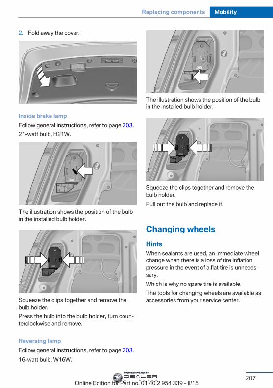
2. Fold away the cover.
Inside brake lampFollow general instructions, refer to page 203.21-watt bulb, H21W.
The illustration shows the position of the bulbin the installed bulb holder.
Squeeze the clips together and remove thebulb holder.Press the bulb into the bulb holder, turn coun‐terclockwise and remove.
Reversing lampFollow general instructions, refer to page 203.16-watt bulb, W16W.
The illustration shows the position of the bulbin the installed bulb holder.
Squeeze the clips together and remove thebulb holder.Pull out the bulb and replace it.
Changing wheelsHintsWhen sealants are used, an immediate wheelchange when there is a loss of tire inflationpressure in the event of a flat tire is unneces‐sary.Which is why no spare tire is available.The tools for changing wheels are available asaccessories from your service center.
Seite 207
Replacing components Mobility
207Online Edition for Part no. 01 40 2 954 339 - II/15
Information Provided by:
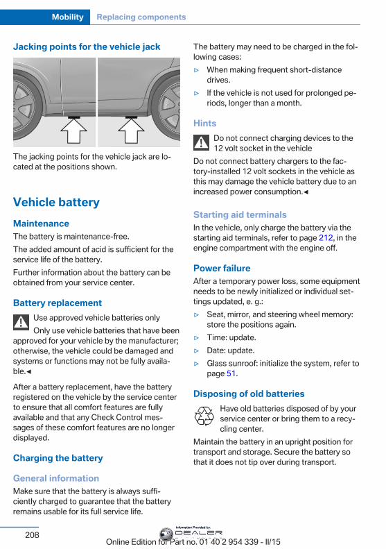
Jacking points for the vehicle jack
The jacking points for the vehicle jack are lo‐cated at the positions shown.
Vehicle batteryMaintenanceThe battery is maintenance-free.The added amount of acid is sufficient for theservice life of the battery.Further information about the battery can beobtained from your service center.
Battery replacementUse approved vehicle batteries onlyOnly use vehicle batteries that have been
approved for your vehicle by the manufacturer;otherwise, the vehicle could be damaged andsystems or functions may not be fully availa‐ble.◀
After a battery replacement, have the batteryregistered on the vehicle by the service centerto ensure that all comfort features are fullyavailable and that any Check Control mes‐sages of these comfort features are no longerdisplayed.
Charging the battery
General informationMake sure that the battery is always suffi‐ciently charged to guarantee that the batteryremains usable for its full service life.
The battery may need to be charged in the fol‐lowing cases:▷ When making frequent short-distance
drives.▷ If the vehicle is not used for prolonged pe‐
riods, longer than a month.
HintsDo not connect charging devices to the12 volt socket in the vehicle
Do not connect battery chargers to the fac‐tory-installed 12 volt sockets in the vehicle asthis may damage the vehicle battery due to anincreased power consumption.◀
Starting aid terminalsIn the vehicle, only charge the battery via thestarting aid terminals, refer to page 212, in theengine compartment with the engine off.
Power failureAfter a temporary power loss, some equipmentneeds to be newly initialized or individual set‐tings updated, e. g.:▷ Seat, mirror, and steering wheel memory:
store the positions again.▷ Time: update.▷ Date: update.▷ Glass sunroof: initialize the system, refer to
page 51.
Disposing of old batteriesHave old batteries disposed of by yourservice center or bring them to a recy‐cling center.
Maintain the battery in an upright position fortransport and storage. Secure the battery sothat it does not tip over during transport.
Seite 208
Mobility Replacing components
208Online Edition for Part no. 01 40 2 954 339 - II/15
Information Provided by:
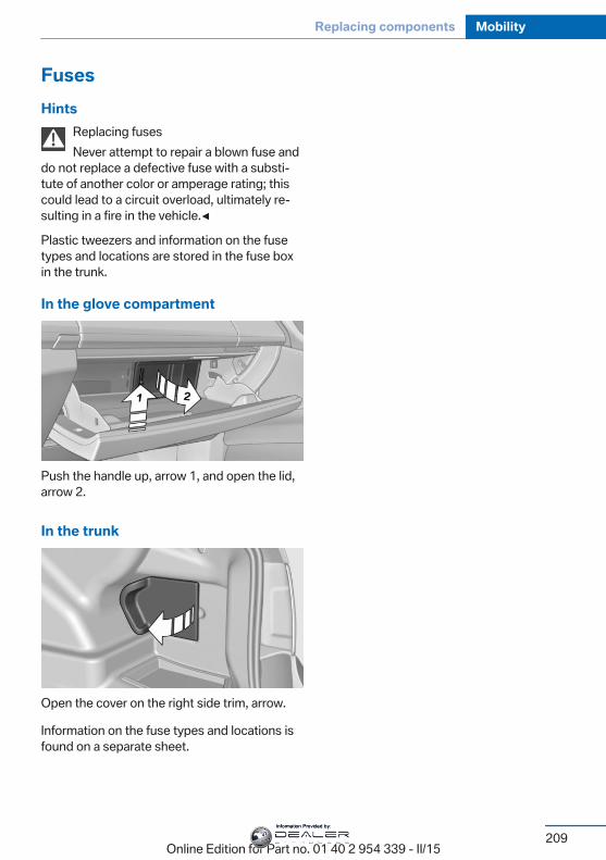
FusesHints
Replacing fusesNever attempt to repair a blown fuse and
do not replace a defective fuse with a substi‐tute of another color or amperage rating; thiscould lead to a circuit overload, ultimately re‐sulting in a fire in the vehicle.◀
Plastic tweezers and information on the fusetypes and locations are stored in the fuse boxin the trunk.
In the glove compartment
Push the handle up, arrow 1, and open the lid,arrow 2.
In the trunk
Open the cover on the right side trim, arrow.
Information on the fuse types and locations isfound on a separate sheet.
Seite 209
Replacing components Mobility
209Online Edition for Part no. 01 40 2 954 339 - II/15
Information Provided by:
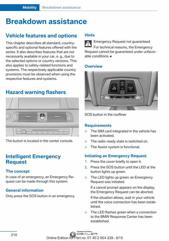
Breakdown assistanceVehicle features and optionsThis chapter describes all standard, country-specific and optional features offered with theseries. It also describes features that are notnecessarily available in your car, e. g., due tothe selected options or country versions. Thisalso applies to safety-related functions andsystems. The respectively applicable countryprovisions must be observed when using therespective features and systems.
Hazard warning flashers
The button is located in the center console.
Intelligent EmergencyRequestThe conceptIn case of an emergency, an Emergency Re‐quest can be made through this system.
General informationOnly press the SOS button in an emergency.
HintsEmergency Request not guaranteedFor technical reasons, the Emergency
Request cannot be guaranteed under unfavor‐able conditions.◀
Overview
SOS button in the roofliner
Requirements▷ The SIM card integrated in the vehicle has
been activated.▷ The radio-ready state is switched on.▷ The Assist system is functional.
Initiating an Emergency Request1. Press the cover briefly to open it.2. Press the SOS button until the LED at the
button lights up green.▷ The LED lights up green: an Emergency
Request was initiated.If a cancel prompt appears on the display,the Emergency Request can be aborted.If the situation allows, wait in your vehicleuntil the voice connection has been estab‐lished.
▷ The LED flashes green when a connectionto the BMW Response Center has beenestablished.
Seite 210
Mobility Breakdown assistance
210Online Edition for Part no. 01 40 2 954 339 - II/15
Information Provided by:
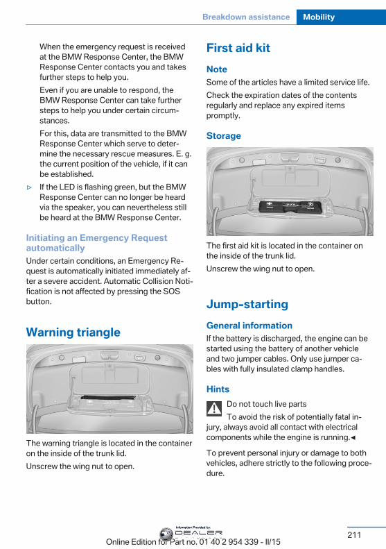
When the emergency request is receivedat the BMW Response Center, the BMWResponse Center contacts you and takesfurther steps to help you.Even if you are unable to respond, theBMW Response Center can take furthersteps to help you under certain circum‐stances.For this, data are transmitted to the BMWResponse Center which serve to deter‐mine the necessary rescue measures. E. g.the current position of the vehicle, if it canbe established.
▷ If the LED is flashing green, but the BMWResponse Center can no longer be heardvia the speaker, you can nevertheless stillbe heard at the BMW Response Center.
Initiating an Emergency RequestautomaticallyUnder certain conditions, an Emergency Re‐quest is automatically initiated immediately af‐ter a severe accident. Automatic Collision Noti‐fication is not affected by pressing the SOSbutton.
Warning triangle
The warning triangle is located in the containeron the inside of the trunk lid.Unscrew the wing nut to open.
First aid kitNoteSome of the articles have a limited service life.Check the expiration dates of the contentsregularly and replace any expired itemspromptly.
Storage
The first aid kit is located in the container onthe inside of the trunk lid.Unscrew the wing nut to open.
Jump-startingGeneral informationIf the battery is discharged, the engine can bestarted using the battery of another vehicleand two jumper cables. Only use jumper ca‐bles with fully insulated clamp handles.
HintsDo not touch live partsTo avoid the risk of potentially fatal in‐
jury, always avoid all contact with electricalcomponents while the engine is running.◀
To prevent personal injury or damage to bothvehicles, adhere strictly to the following proce‐dure.
Seite 211
Breakdown assistance Mobility
211Online Edition for Part no. 01 40 2 954 339 - II/15
Information Provided by:
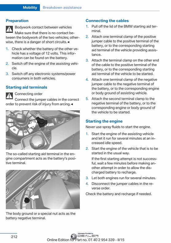
PreparationBodywork contact between vehiclesMake sure that there is no contact be‐
tween the bodywork of the two vehicles; other‐wise, there is a danger of short circuits.◀
1. Check whether the battery of the other ve‐hicle has a voltage of 12 volts. This infor‐mation can be found on the battery.
2. Switch off the engine of the assisting vehi‐cle.
3. Switch off any electronic systems/powerconsumers in both vehicles.
Starting aid terminalsConnecting orderConnect the jumper cables in the correct
order to prevent risk of injury from arcing.◀
The so-called starting aid terminal in the en‐gine compartment acts as the battery's posi‐tive terminal.
The body ground or a special nut acts as thebattery negative terminal.
Connecting the cables1. Pull off the lid of the BMW starting aid ter‐
minal.2. Attach one terminal clamp of the positive
jumper cable to the positive terminal of thebattery, or to the corresponding startingaid terminal of the vehicle providing assis‐tance.
3. Attach the terminal clamp on the other endof the cable to the positive terminal of thebattery, or to the corresponding startingaid terminal of the vehicle to be started.
4. Attach one terminal clamp of the negativejumper cable to the negative terminal ofthe battery, or to the corresponding engineor body ground of assisting vehicle.
5. Attach the second terminal clamp to thenegative terminal of the battery, or to thecorresponding engine or body ground ofthe vehicle to be started.
Starting the engineNever use spray fluids to start the engine.
1. Start the engine of the assisting vehicleand let it run for several minutes at an in‐creased idle speed.
2. Start the engine of the vehicle that is to bestarted in the usual way.If the first starting attempt is not success‐ful, wait a few minutes before making an‐other attempt in order to allow the dis‐charged battery to recharge.
3. Let both engines run for several minutes.4. Disconnect the jumper cables in the re‐
verse order.Check the battery and recharge if needed.
Seite 212
Mobility Breakdown assistance
212Online Edition for Part no. 01 40 2 954 339 - II/15
Information Provided by:
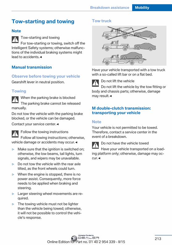
Tow-starting and towingNote
Tow-starting and towingFor tow-starting or towing, switch off the
Intelligent Safety systems; otherwise malfunc‐tions of the individual braking systems mightlead to accidents.◀
Manual transmission
Observe before towing your vehicleGearshift lever in neutral position.
TowingWhen the parking brake is blockedThe parking brake cannot be released
manually.Do not tow the vehicle with the parking brakeblocked, or the vehicle can be damaged.Contact your service center.◀
Follow the towing instructionsFollow all towing instructions; otherwise,
vehicle damage or accidents may occur.◀
▷ Make sure that the ignition is switched on;otherwise, the low beams, tail lights, turnsignals, and wipers may be unavailable.
▷ Do not tow the vehicle with the rear axletilted, as the front wheels could turn.
▷ When the engine is stopped, there is nopower assist. Consequently, more forceneeds to be applied when braking andsteering.
▷ Larger steering wheel movements are re‐quired.
▷ The towing vehicle must not be lighterthan the vehicle being towed; otherwise,it will not be possible to control the vehi‐cle's response.
Tow truck
Have your vehicle transported with a tow truckwith a so-called lift bar or on a flat bed.
Do not lift the vehicleDo not lift the vehicle by the tow fitting or
body and chassis parts; otherwise, damagemay result.◀
M double-clutch transmission:transporting your vehicle
NoteYour vehicle is not permitted to be towed.Therefore, contact a service center in theevent of a breakdown.
Do not have the vehicle towedHave your vehicle transported on a load‐
ing platform only; otherwise, damage may oc‐cur.◀
Seite 213
Breakdown assistance Mobility
213Online Edition for Part no. 01 40 2 954 339 - II/15
Information Provided by:
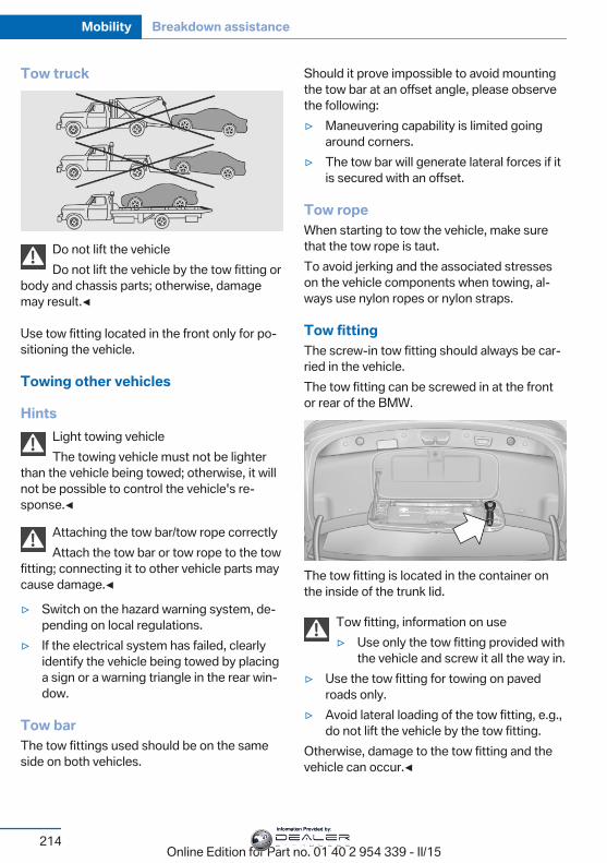
Tow truck
Do not lift the vehicleDo not lift the vehicle by the tow fitting or
body and chassis parts; otherwise, damagemay result.◀
Use tow fitting located in the front only for po‐sitioning the vehicle.
Towing other vehicles
HintsLight towing vehicleThe towing vehicle must not be lighter
than the vehicle being towed; otherwise, it willnot be possible to control the vehicle's re‐sponse.◀
Attaching the tow bar/tow rope correctlyAttach the tow bar or tow rope to the tow
fitting; connecting it to other vehicle parts maycause damage.◀
▷ Switch on the hazard warning system, de‐pending on local regulations.
▷ If the electrical system has failed, clearlyidentify the vehicle being towed by placinga sign or a warning triangle in the rear win‐dow.
Tow barThe tow fittings used should be on the sameside on both vehicles.
Should it prove impossible to avoid mountingthe tow bar at an offset angle, please observethe following:▷ Maneuvering capability is limited going
around corners.▷ The tow bar will generate lateral forces if it
is secured with an offset.
Tow ropeWhen starting to tow the vehicle, make surethat the tow rope is taut.To avoid jerking and the associated stresseson the vehicle components when towing, al‐ways use nylon ropes or nylon straps.
Tow fittingThe screw-in tow fitting should always be car‐ried in the vehicle.The tow fitting can be screwed in at the frontor rear of the BMW.
The tow fitting is located in the container onthe inside of the trunk lid.
Tow fitting, information on use▷ Use only the tow fitting provided with
the vehicle and screw it all the way in.▷ Use the tow fitting for towing on paved
roads only.▷ Avoid lateral loading of the tow fitting, e.g.,
do not lift the vehicle by the tow fitting.Otherwise, damage to the tow fitting and thevehicle can occur.◀
Seite 214
Mobility Breakdown assistance
214Online Edition for Part no. 01 40 2 954 339 - II/15
Information Provided by:
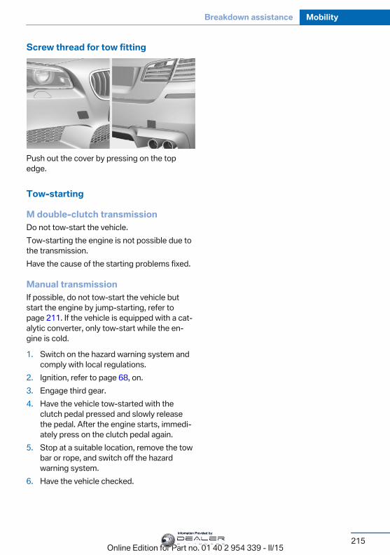
Screw thread for tow fitting
Push out the cover by pressing on the topedge.
Tow-starting
M double-clutch transmissionDo not tow-start the vehicle.Tow-starting the engine is not possible due tothe transmission.Have the cause of the starting problems fixed.
Manual transmissionIf possible, do not tow-start the vehicle butstart the engine by jump-starting, refer topage 211. If the vehicle is equipped with a cat‐alytic converter, only tow-start while the en‐gine is cold.
1. Switch on the hazard warning system andcomply with local regulations.
2. Ignition, refer to page 68, on.3. Engage third gear.4. Have the vehicle tow-started with the
clutch pedal pressed and slowly releasethe pedal. After the engine starts, immedi‐ately press on the clutch pedal again.
5. Stop at a suitable location, remove the towbar or rope, and switch off the hazardwarning system.
6. Have the vehicle checked.
Seite 215
Breakdown assistance Mobility
215Online Edition for Part no. 01 40 2 954 339 - II/15
Information Provided by:
CareVehicle features and optionsThis chapter describes all standard, country-specific and optional features offered with theseries. It also describes features that are notnecessarily available in your car, e. g., due tothe selected options or country versions. Thisalso applies to safety-related functions andsystems. The respectively applicable countryprovisions must be observed when using therespective features and systems.
Car washesGeneral informationRegularly remove foreign objects such asleaves in the area below the windshield whenthe hood is raised.Wash your vehicle frequently, particularly inwinter. Intense soiling and road salt can dam‐age the vehicle.
HintsSteam jets or high-pressure washersWhen using steam jets or high-pressure
washers, hold them a sufficient distance awayand use a maximum temperature of140 ℉/60 ℃.If the vehicle has a glass sunroof, ensure that adistance of at least 31.5 inches/80 cm is main‐tained. Holding them too close or using exces‐sively high pressures or temperatures cancause damage or preliminary damage that maythen lead to long-term damage.Follow the user's manual for the high-pressurewasher.◀
Cleaning sensors/camera lenses withhigh-pressure washers
When using high-pressure washers, do notspray the sensors and camera lenses on theoutside of the vehicle for long periods andmaintain a distance of at least 12 in/30 cm.◀
Automatic car washes
HintsNote the following:▷ Give preference to cloth car washes or
those that use soft brushes in order toavoid paint damage.
▷ Make sure that the wheels and tires are notdamaged by the transport mechanisms.
▷ Fold in the exterior mirrors; otherwise, theymay be damaged, depending on the widthof the vehicle.
▷ Deactivate the rain sensor, refer topage 75, to avoid unintentional wiper acti‐vation.
▷ In some cases, an unintentional alarm canbe triggered by the interior motion sensorof the alarm system. Follow the instruc‐tions on avoiding an unintentional alarm,refer to page 48.
Guide rails in car washesAvoid car washes with guide rails higher
than 4 in/10 cm; otherwise, the vehicle bodycould be damaged.◀
Before driving into a car washIn order to ensure that the vehicle can roll in acar wash, take the following steps:Manual transmission:
1. Drive into the car wash.2. Shift to neutral.
Seite 216
Mobility Care
216Online Edition for Part no. 01 40 2 954 339 - II/15
Information Provided by:
3. Switch the engine off.4. Switch on the ignition.M double-clutch transmission:
1. Drive into the car wash.2. Engage selector lever position N.3. Switch the engine off.
In this way, the ignition remains switchedon, and a Check-Control message is dis‐played.
Do not turn off the ignition in the carwash
Do not turn off the ignition in the car wash;otherwise, the transmission position P isengaged and damages can result.◀
The vehicle cannot be locked from the outsidewhen in selector lever position N. A signalsounds when an attempt is made to lock thevehicle.To start the engine with manual transmission:
1. Press on the clutch pedal.2. Press the Start/Stop button.To start the engine with a M double clutchtransmission:
1. Depress the brake pedal.2. Press the Start/Stop button.Pressing the Start/Stop button without step‐ping on the brake turns the ignition off.
Transmission positionTransmission position P is engaged automati‐cally:▷ When the ignition is switched off.▷ After approx. 15 minutes.
Headlights▷ Do not rub dry and do not use abrasive or
acidic cleansers.
▷ Soak areas that have been dirtied e. g.,from insects, with shampoo and wash offwith water.
▷ Thaw ice with de-icing spray; do not use anice scraper.
After washing the vehicleAfter washing the vehicle, apply the brakesbriefly to dry them; otherwise, braking actioncan be reduced and corrosion of the brakediscs can occur.Completely remove all residues on the win‐dows, to minimize loss of visibility due tosmearing and to reduce wiper noises andwiper blade wear.
Vehicle careCar care productsBMW recommends using care and cleaningproducts from BMW, since these have beentested and approved.
Car care and cleaning productsFollow the instructions on the container.
When cleaning the interior, open the doors orwindows.Only use products intended for cleaning vehi‐cles.Cleansers can contain substances that aredangerous and harmful to your health.◀
Vehicle paintRegular care contributes to driving safety andvalue retention. Environmental influences inareas with elevated air pollution or natural con‐taminants, such as tree resin or pollen can af‐fect the vehicle's paintwork. Tailor the fre‐quency and extent of your car care to theseinfluences.Aggressive substances such as spilled fuel, oil,grease or bird droppings, must be removed im‐
Seite 217
Care Mobility
217Online Edition for Part no. 01 40 2 954 339 - II/15
Information Provided by:
mediately to prevent the finish from being al‐tered or discolored.Only use respectively approved cleaning andcare products for vehicles with matte finish.Suitable care products for matte finishes areavailable from the service center.
Leather careRemove dust from the leather often, using acloth or vacuum cleaner.Otherwise, particles of dust and road grimechafe in pores and folds, and lead to increasedwear and premature degradation of the leathersurface.To guard against discoloration, such as fromclothing, provide leather care roughly everytwo months.Clean light-colored leather more frequently be‐cause soiling on such surfaces is substantiallymore visible.Use leather care products; otherwise, dirt andgrease will gradually break down the protectivelayer of the leather surface.Suitable care products are available from theservice center.
Upholstery material careVacuum regularly with a vacuum cleaner.If upholstery is very dirty, e.g., with beveragestains, use a soft sponge or microfiber clothwith a suitable interior cleaner.Clean the upholstery down to the seams usinglarge sweeping motions. Avoid rubbing thematerial vigorously.
Damage from Velcro® fastenersOpen Velcro® fasteners on pants or
other articles of clothing can damage the seatcovers. Ensure that any Velcro® fasteners areclosed.◀
Caring for special components
Light-alloy wheelsWhen cleaning the vehicle, use only neutralwheel cleaners having a pH value from 5 to 9.Do not use abrasive cleaning agents or steamjets above 140 ℉/60 ℃. Follow the manufac‐turer's instructions.Aggressive, acidic or alkaline cleaning agentscan destroy the protective layer of adjacentcomponents, such as the brake disk.
Chrome surfacesCarefully clean components such as the radia‐tor grille or door handles with an ample supplyof water, possibly with shampoo added, partic‐ularly when they have been exposed to roadsalt.
Rubber componentsAside from water, treat only with rubbercleansers.When cleaning rubber seals, do not use anysilicon-containing car care products in order toavoid damage or noises.
Fine wood partsClean fine wood facing and fine wood compo‐nents only with a moist rag. Then dry with asoft cloth.
Plastic componentsThese include:▷ Imitation leather surfaces.▷ Roofliner.▷ Lamp lenses.▷ Instrument cluster cover.▷ Matt black spray-coated components.▷ Painted parts in the interior.Clean with a microfiber cloth.Dampen cloth lightly with water.Do not soak the roofliner.
Seite 218
Mobility Care
218Online Edition for Part no. 01 40 2 954 339 - II/15
Information Provided by:
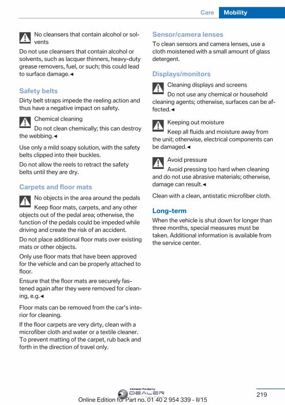
No cleansers that contain alcohol or sol‐vents
Do not use cleansers that contain alcohol orsolvents, such as lacquer thinners, heavy-dutygrease removers, fuel, or such; this could leadto surface damage.◀
Safety beltsDirty belt straps impede the reeling action andthus have a negative impact on safety.
Chemical cleaningDo not clean chemically; this can destroy
the webbing.◀
Use only a mild soapy solution, with the safetybelts clipped into their buckles.Do not allow the reels to retract the safetybelts until they are dry.
Carpets and floor matsNo objects in the area around the pedalsKeep floor mats, carpets, and any other
objects out of the pedal area; otherwise, thefunction of the pedals could be impeded whiledriving and create the risk of an accident.Do not place additional floor mats over existingmats or other objects.Only use floor mats that have been approvedfor the vehicle and can be properly attached tofloor.Ensure that the floor mats are securely fas‐tened again after they were removed for clean‐ing, e.g.◀
Floor mats can be removed from the car's inte‐rior for cleaning.If the floor carpets are very dirty, clean with amicrofiber cloth and water or a textile cleaner.To prevent matting of the carpet, rub back andforth in the direction of travel only.
Sensor/camera lensesTo clean sensors and camera lenses, use acloth moistened with a small amount of glassdetergent.
Displays/monitorsCleaning displays and screensDo not use any chemical or household
cleaning agents; otherwise, surfaces can be af‐fected.◀
Keeping out moistureKeep all fluids and moisture away from
the unit; otherwise, electrical components canbe damaged.◀
Avoid pressureAvoid pressing too hard when cleaning
and do not use abrasive materials; otherwise,damage can result.◀
Clean with a clean, antistatic microfiber cloth.
Long-termWhen the vehicle is shut down for longer thanthree months, special measures must betaken. Additional information is available fromthe service center.
Seite 219
Care Mobility
219Online Edition for Part no. 01 40 2 954 339 - II/15
Information Provided by:
Online Edition for Part no. 01 40 2 954 339 - II/15
Information Provided by:

ReferenceThis chapter contains the technical data and an
index that will quickly take you to the informationyou need.
Online Edition for Part no. 01 40 2 954 339 - II/15
Information Provided by:
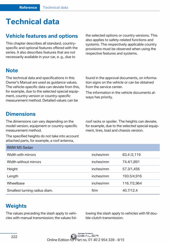
Technical dataVehicle features and optionsThis chapter describes all standard, country-specific and optional features offered with theseries. It also describes features that are notnecessarily available in your car, e. g., due to
the selected options or country versions. Thisalso applies to safety-related functions andsystems. The respectively applicable countryprovisions must be observed when using therespective features and systems.
NoteThe technical data and specifications in thisOwner's Manual are used as guidance values.The vehicle-specific data can deviate from this,for example, due to the selected special equip‐ment, country version or country-specificmeasurement method. Detailed values can be
found in the approval documents, on informa‐tion signs on the vehicle or can be obtainedfrom the service center.The information in the vehicle documents al‐ways has priority.
DimensionsThe dimensions can vary depending on themodel version, equipment or country-specificmeasurement method.The specified heights do not take into accountattached parts, for example, a roof antenna,
roof racks or spoiler. The heights can deviate,for example, due to the selected special equip‐ment, tires, load and chassis version.
BMW M5 Sedan
Width with mirrors inches/mm 83.4 /2,119
Width without mirrors inches/mm 74.4/1,891
Height inches/mm 57.3/1,456
Length inches/mm 193.5/4,916
Wheelbase inches/mm 116.7/2,964
Smallest turning radius diam. ft/m 40.7/12.4
WeightsThe values preceding the slash apply to vehi‐cles with manual transmission; the values fol‐
lowing the slash apply to vehicles with M dou‐ble-clutch transmission.
Seite 222
Reference Technical data
222Online Edition for Part no. 01 40 2 954 339 - II/15
Information Provided by:
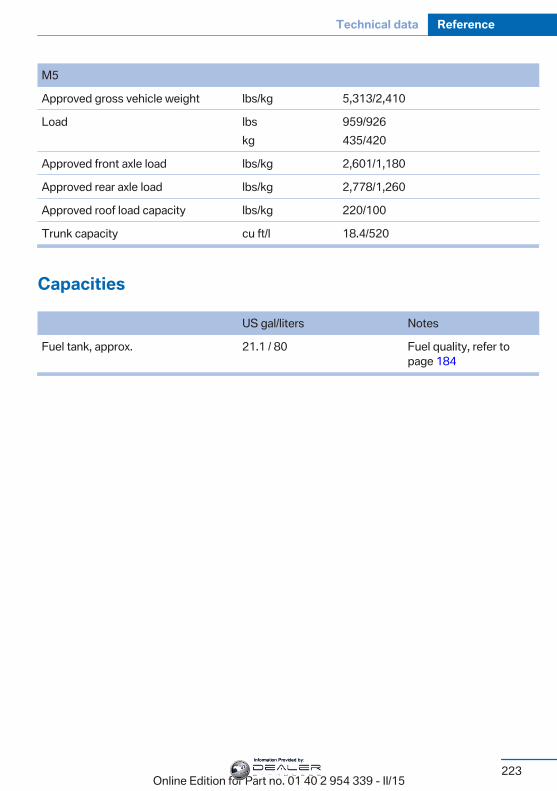
M5
Approved gross vehicle weight lbs/kg 5,313/2,410
Load lbskg
959/926435/420
Approved front axle load lbs/kg 2,601/1,180
Approved rear axle load lbs/kg 2,778/1,260
Approved roof load capacity lbs/kg 220/100
Trunk capacity cu ft/l 18.4/520
Capacities
US gal/liters Notes
Fuel tank, approx. 21.1 / 80 Fuel quality, refer topage 184
Seite 223
Technical data Reference
223Online Edition for Part no. 01 40 2 954 339 - II/15
Information Provided by:
Everything from A to ZIndexAABS, Antilock Brake Sys‐
tem 127 Acceleration Assistant, refer
to Launch Control 80 Accessories and parts 7 Activated-charcoal filter 147 Active Blind Spot Detec‐
tion 122 Active M differential 131 Active Protection 124 Active seat, front 55 Active seat ventilation,
front 56 Adaptive brake lights, refer to
Brake force display 124 Adaptive Light Control 101 Additives, oil 198 Adjustments, seats/head re‐
straints 53 After washing vehicle 217 Airbags 105 Airbags, indicator/warning
light 106 Air circulation, refer to Recir‐
culated-air mode 146 Air, dehumidifying, refer to
Cooling function 146 Air distribution, manual 145 Air flow, automatic climate
control 145 Air outlets, see ventila‐
tion 147 Air pressure, tires 186 Alarm system 47 Alarm, unintentional 48 All around the center con‐
sole 16 All around the roofliner 17
All around the steeringwheel 14
All-season tires, refer to Win‐ter tires 191
Alternating-code hand-heldtransmitter 152
Alternative oil types 199 Ambient light 104 Animal detection, see Night
Vision 118 Antifreeze, washer fluid 76 Antilock Brake System,
ABS 127 Anti-slip control, refer to
DSC 129 Approved axle load 222 Approved engine oils, see
Suitable engine oiltypes 199
Armrest, refer to Center arm‐rest 161
Arrival time 94 Ashtray 153 Ashtray, front 153, 154 Ashtray, rear 154 Assistance when driving
off 127 Attentiveness assistant 124 AUTO intensity 145 Automatic car wash 216 Automatic climate con‐
trol 144 Automatic Curb Monitor 61 Automatic deactivation, front-
seat passenger airbags 107 Automatic headlight con‐
trol 101 Automatic locking 46 Automatic recirculated-air
control 146
Automatic Soft Closing,doors 40
Automatic trunk lid 41 AUTO program, automatic cli‐
mate control 145 AUTO program, intensity 145 Auto Start/Stop function 70 Average fuel consumption 94 Average speed 94 Axle loads, weights 222
BBackrest curvature, refer to
Lumbar support 54 Backrest, width 54 Band-aids, refer to First aid
kit 211 Bar for tow-starting/
towing 214 Battery replacement, vehicle
battery 208 Battery replacement, vehicle
remote control 35 Battery, vehicle 208 Belts, safety belts 56 Beverage holder, cu‐
pholder 162 Blinds, sun protection 49 BMW Assist, see user's
manual for Navigation, En‐tertainment and Communi‐cation
BMW Driver’s Guide App 6 BMW Homepage 6 BMW Internet page 6 BMW maintenance sys‐
tem 201 BMW M technology 168 Bottle holder, refer to Cu‐
pholder 162
Seite 224
Reference Everything from A to Z
224Online Edition for Part no. 01 40 2 954 339 - II/15
Information Provided by:
Brake assistant 127 Brake discs, break-in 170 Brake force display 124 Brake lights, adaptive 124 Brake lights, brake force dis‐
play 124 Brake lights, bulb replace‐
ment 206 Brake pads, break-in 170 Braking, hints 172 Breakdown assistance 210 Break-in 170 Brightness of Control Dis‐
play 97 Bulb replacement 203 Bulb replacement, front 204 Bulb replacement, rear 206 Bulbs and lights 203 Button, Start/Stop 68 Bypassing, refer to Jump-
starting 211
CCalifornia Proposition 65
Warning 7 Calling up mirror adjust‐
ment 46 Calling up seat adjust‐
ment 46 Calling up steering wheel ad‐
justment 46 Camera lenses, care 219 Camera, rearview cam‐
era 138 Camera, Side View 140 Camera, Top View 142 Can holder, refer to Cu‐
pholder 162 Car battery 208 Carbon ceramic brake M 168 Car care products 217 Care, displays 219 Care, vehicle 217 Cargo 174 Cargo area, enlarging 156
Cargo area, storage compart‐ments 163
Cargo, securing 175 Cargo straps, securing
cargo 175 Car key, refer to Remote con‐
trol 34 Carpet, care 219 Car wash 216 Catalytic converter, refer to
Hot exhaust system 171 CBS Condition Based Serv‐
ice 201 CD/Multimedia, see user's
manual for Navigation, En‐tertainment and Communi‐cation
Center armrest 161 Center console 16 Central locking system 40 Central screen, refer to Con‐
trol Display 18 Ceramic brake 168 Changes, technical, refer to
Safety 7 Changing parts 203 Changing wheels 207 Changing wheels/tires 190 Chassis number, see vehicle
identification number 9 Check Control 84 Checking the engine oil level
electronically 197 Checking the oil level elec‐
tronically 197 Children, seating position 64 Children, transporting
safely 64 Child restraint fixing sys‐
tem 64 Child restraint fixing system
LATCH 65 Child restraint fixing systems,
mounting 64 Child safety locks 67 Child seat, mounting 64
Child seats 64 Chrome parts, care 218 Cigarette lighter 153 Cleaning displays 219 Climate control 144 Climate control laminated
tinted safety glass 171 Climate control wind‐
shield 171 Clock 88 Closing/opening via door
lock 39 Closing/opening with remote
control 37 Closing the trunk lid with no-
touch activation 44 Clothes hooks 163 Combination reel, refer to
Turn signals 74 Combination switch, refer to
Wiper system 74 Comfort Access 43 Compound brake 168 Compressor 191 Computer, refer to On-board
computer 93 Condensation on win‐
dows 145 Condensation under the vehi‐
cle 173 Condition Based Service
CBS 201 Confirmation signal 46 ConnectedDrive, see user's
manual for Navigation, En‐tertainment and Communi‐cation
ConnectedDrive Services Control Display 18 Control Display, settings 96 Controller 18 Control systems, driving sta‐
bility 127 Convenient opening with the
remote control 37 Coolant 200
Seite 225
Everything from A to Z Reference
225Online Edition for Part no. 01 40 2 954 339 - II/15
Information Provided by:
Coolant level 200 Coolant temperature 88 Cooling function 146 Cooling, maximum 146 Cooling system 200 Cornering light 101 Corrosion on brake discs 173 Cosmetic mirror 153 Courtesy lamps during un‐
locking 37 Courtesy lamps with the vehi‐
cle locked 38 Cruise control 133 Cruising range 89 Cupholder 162 Current fuel consumption 89
DDamage, tires 189 Damping control 131 Damping control, dy‐
namic 131 Data, technical 222 Date 88 Daytime running lights 101 Defrosting, refer to Windows,
defrosting 145 Dehumidifying, air 146 Deleting personal data 24 Deletion of personal data 24 Destination distance 94 Differential lock 131 Digital clock 88 Digital speed 88 Digital tachometer 88 Dimensions 222 Dimmable exterior mirrors 61 Dimmable interior rearview
mirror 62 Direction indicator, refer to
Turn signals 74 Display EfficientDynamics 90 Display, electronic, instru‐
ment cluster 83 Display in windshield 97
Display lighting, refer to In‐strument lighting 103
Displays, cleaning 219 Disposal, coolant 200 Disposal, vehicle battery 208 Distance control, refer to
PDC 135 Distance to destination 94 Divided screen view, split
screen 23 Door lock 39 Door lock, refer to Remote
control 34 Doors, Automatic Soft Clos‐
ing 40 Double-clutch transmis‐
sion 77 Drivelogic 79 Drive mode 78 Drive-off assistant 127 Drive-off assistant, refer to
DSC 129 Driver assistance, refer to In‐
telligent Safety 112 Driving Assistant, refer to In‐
telligent Safety 112 Driving Dynamics Control 81 Driving instructions, break-
in 170 Driving notes, general 171 Driving on racetracks 169 Driving program, refer to
Drivelogic 79 Driving stability control sys‐
tems 127 Driving tips 171 DSC Dynamic Stability Con‐
trol 129 Dynamic Damping Con‐
trol 131 Dynamic driving systems 90 Dynamic driving, system
states 90 Dynamic Stability Control
DSC 129
EEfficientDynamics 90 Electronic displays, instru‐
ment cluster 83 Electronic oil measure‐
ment 197 Electronic Stability Program
ESP, refer to DSC 129 Emergency detection, remote
control 35 Emergency release, fuel filler
flap 182 Emergency Request 210 Emergency start function, en‐
gine start 35 Emergency unlocking, trunk
lid 43 Energy Control 89 Energy recovery 89 Engine, automatic Start/Stop
function 70 Engine, automatic switch-
off 70 Engine compartment 195 Engine compartment, work‐
ing in 195 Engine coolant 200 Engine oil 197 Engine oil, adding 198 Engine oil additives 198 Engine oil change 199 Engine oil filler neck 198 Engine oil temperature 87 Engine oil types, alterna‐
tive 199 Engine oil types, ap‐
proved 199 Engine start during malfunc‐
tion 35 Engine start, jump-start‐
ing 211 Engine start, refer to Starting
the engine 69 Engine stop 69 Engine temperature 87
Seite 226
Reference Everything from A to Z
226Online Edition for Part no. 01 40 2 954 339 - II/15
Information Provided by:
Entering a car wash 216 Equipment, interior 151 Error displays, see Check
Control 84 ESP Electronic Stability Pro‐
gram, refer to DSC 129 Exchanging wheels/tires 190 Exhaust system 171 Exterior mirror, automatic
dimming feature 61 Exterior mirrors 60 External start 211 External temperature dis‐
play 88 External temperature warn‐
ing 88 Eyes for securing cargo 175
FFailure message, see Check
Control 84 False alarm, refer to Uninten‐
tional alarm 48 Fan, refer to Air flow 145 Filler neck for engine oil 198 Fine wood, care 218 First aid kit 211 Fitting for towing, see Tow fit‐
ting 214 Flat tire, changing
wheels 207 Flat Tire Monitor FTM 111 Flat tire, Tire Pressure Moni‐
tor TPM 108 Flat tire, warning
lamp 109, 111 Flooding 172 Floor carpet, care 219 Floor mats, care 219 Fold down the rear seat back‐
rest, see Though-loadingsystem 156
Fold-out position, wiper 76 Foot brake 172 Front airbags 105
Front-end collision warningwith City Braking func‐tion 113
Front lights 204 front-seat passenger airbags,
automatic deactivation 107 Front-seat passenger airbags,
indicator lamp 107 FTM Flat Tire Monitor 111 Fuel 184 Fuel consumption, refer to
Average fuel consump‐tion 94
Fuel filler flap 182 Fuel gauge 87 Fuel lid 182 Fuel quality 184 Fuel recommendation 184 Fuel, tank capacity 223 Fuse 209
GGarage door opener, refer to
Universal Integrated RemoteControl 151
Gasoline 184 Gear change 79 Gear shift indicator 91 General driving notes 171 Glare shield 153 Glass sunroof, powered 50 Glove compartment 160 Gross vehicle weight, ap‐
proved 222 Ground clearance 173
HHandbrake, refer to Parking
brake 72 Hand-held transmitter, alter‐
nating code 152 Hazard warning flashers 210 Head airbags 105
Headlight control, auto‐matic 101
Headlight courtesy delay fea‐ture 100
Headlight courtesy delay fea‐ture via remote control 38
Headlight flasher 74 Headlight glass 204 Headlights 204 Headlights, care 217 Headlight washer system 74 Head restraints 53 Head restraints, front 57 Head restraints, rear 58 Head-up Display 97 Head-up Display, care 219 Head-up display, M view 98 Head-up display, standard
view 98 Heavy cargo, stowing 175 Height, vehicle 222 High-beam Assistant 102 High beams 74 High beams/low beams, refer
to High-beam Assistant 102 Higher speed range 173 Hills 172 Hill start assistant, refer to
Drive-off assistant 127 Hints 6 Holder for beverages 162 Homepage 6 Hood 195 Horn 14 Hotel function, trunk lid 42 Hot exhaust system 171 HUD Head-up Display 97 Hydroplaning 171
IIce warning, see External
temperature warning 88 Icy roads, see External tem‐
perature warning 88 Identification marks, tires 187
Seite 227
Everything from A to Z Reference
227Online Edition for Part no. 01 40 2 954 339 - II/15
Information Provided by:
Identification number, see ve‐hicle identification num‐ber 9
iDrive 18 Ignition key, refer to Remote
control 34 Ignition off 68 Ignition on 68 Indication of a flat
tire 109, 111 Indicator and alarm lamps,
see Check Control 84 Indicator lamp, see Check
Control 84 Individual air distribution 145 Individual settings, refer to M
Drive 127 Individual settings, refer to
Personal Profile 35 Inflation pressure, tires 186 Inflation pressure warning
FTM, tires 111 Info display, refer to On-
Board computer 93 Initialize, Tire Pressure Moni‐
tor TPM 109 Initializing, Flat Tire Monitor
FTM 111 Instrument cluster 83 Instrument cluster, electronic
displays 83 Instrument lighting 103 Integrated key 34 Integrated Owner's Manual in
the vehicle 29 Intelligent Emergency Re‐
quest 210 Intelligent Safety 112 Intensity, AUTO pro‐
gram 145 Interior equipment 151 Interior lights 103 Interior lights during unlock‐
ing 37 Interior lights with the vehicle
locked 38
Interior motion sensor 48 Interior rearview mirror, auto‐
matic dimming feature 62 Interior rearview mirror, man‐
ually dimmable 62 Internet page 6 Interval display, service re‐
quirements 90 Interval mode 75
JJacking points for the vehicle
jack 208 Jump-starting 211
KKey/remote control 34 Keyless Go, refer to Comfort
Access 43 Key Memory, refer to Per‐
sonal Profile 35 Knee airbag 106
LLamp replacement 203 Lamp replacement, front 204 Lamp replacement, rear 206 Lane departure warning 121 Lane margin, warning 121 Language on Control Dis‐
play 96 Lashing eyes, securing
cargo 175 LATCH child restraint sys‐
tem 65 Launch Control 80 Leather, care 218 LED headlights, bulb replace‐
ment 206 LED light 206 LEDs, light-emitting di‐
odes 204 Length, vehicle 222
Letters and numbers, enter‐ing 24
License plate lamp, bulb re‐placement 206
Light alloy wheels, care 218 Light control 101 Light-emitting diodes,
LEDs 204 Lighter, front 153, 154 Lighter, rear 155 Lighting 100 Lighting, speaker 104 Lights 100 Lights and bulbs 203 Light switch 100 Load 175 Loading 174 Lock, door 39 Locking/unlocking via door
lock 39 Locking/unlocking with re‐
mote control 37 Locking, automatic 46 Locking, settings 46 Locking via trunk lid 41 Lock, power window 49 Locks, doors, and win‐
dows 67 Low beams 100 Low beams, automatic, refer
to High-beam Assistant 102 Lower back support 54 Low Speed Assistant 78 Luggage rack, see Roof-
mounted luggage rack 175 Lumbar support 54
MMaintenance 201 Maintenance require‐
ments 201 Maintenance, service require‐
ments 90 Maintenance system,
BMW 201
Seite 228
Reference Everything from A to Z
228Online Edition for Part no. 01 40 2 954 339 - II/15
Information Provided by:
Make-up mirror 153 Malfunction displays, see
Check Control 84 Manual air distribution 145 Manual air flow 145 Manual brake, refer to Parking
brake 72 Manual operation, door
lock 39 Manual operation, exterior
mirrors 61 Manual operation, fuel filler
flap 182 Manual operation, Park Dis‐
tance Control PDC 136 Manual operation, rearview
camera 138 Manual operation, Side
View 141 Manual operation, Top
View 142 Manual transmission 82 Marking on approved
tires 190 Massage seat, front 55 Master key, refer to Remote
control 34 Maximum cooling 146 Maximum speed, display 92 Maximum speed, winter
tires 191 M carbon ceramic brake 168 M Compound brake 168 M differential, active 131 MDM, M Dynamic Mode 129 M double-clutch transmis‐
sion 77 M Drive 127 M Driver's Package, driving
instructions 173 M Driving Dynamics Con‐
trol 81 M Dynamic Mode MDM 129 Measure, units of 97 Medical kit 211
Memory for seat, mirrors,steering wheel 59
Menu EfficientDynamics 90 Menu in instrument clus‐
ter 93 Menus, operating, iDrive 18 Menus, refer to iDrive operat‐
ing concept 19 Messages, see Check Con‐
trol 84 Microfilter 147 Minimum tread, tires 189 Mirror 60 Mirror memory 59 Mobile communication devi‐
ces in the vehicle 171 Mobility System 191 Modifications, technical, refer
to Safety 7 Moisture in headlight 204 Monitor, refer to Control Dis‐
play 18 Mounting of child restraint
systems 64 M technology 168 Multifunction steering wheel,
buttons 14 M view, Head-up display 98
NNavigation, see user's manual
for Navigation, Entertain‐ment and Communication
Neck restraints, front, refer toHead restraints 57
Neck restraints, rear, refer toHead restraints 58
Neutral cleaner, see wheelcleaner 218
New wheels and tires 190 Night Vision 118 Night Vision device, see Night
Vision 118 Nylon rope for tow-starting/
towing 214
OOBD Onboard Diagnosis 202 OBD, see OBD Onboard Di‐
agnosis 202 Object detection, see Night
Vision 118 Obstacle marking, rearview
camera 139 Octane rating, refer to Rec‐
ommended fuel grade 184 Odometer 88 Office, see user's manual for
Navigation, Entertainmentand Communication
Oil 197 Oil, adding 198 Oil additives 198 Oil change 199 Oil change interval, service
requirements 90 Oil filler neck 198 Oil types, alternative 199 Oil types, approved 199 Old batteries, disposal 208 On-board computer 93 Onboard monitor, refer to
Control Display 18 Onboard vehicle tool kit 203 Opening/closing via door
lock 39 Opening and closing 34 Opening and closing, without
remote control 39 Opening and closing, with re‐
mote control 37 Opening the trunk lid with no-
touch activation 44 Operating concept, iDrive 18 Optional equipment, standard
equipment 6 Outside air, refer to Auto‐
matic recirculated-air con‐trol 146
Overheating of engine, referto Coolant temperature 88
Seite 229
Everything from A to Z Reference
229Online Edition for Part no. 01 40 2 954 339 - II/15
Information Provided by:
PPaint, vehicle 217 Park Distance Control
PDC 135 Parked-car ventilation 150 Parked vehicle, condensa‐
tion 173 Parking aid, refer to PDC 135 Parking brake 72 Parking lights 100 Parts and accessories 7 Passenger side mirror, tilting
downward 61 Pathway lines, rearview cam‐
era 139 PDC Park Distance Con‐
trol 135 Pedestrian detection, see
Night Vision 118 Pedestrian warning with city
braking function 115 Personal Profile 35 Personal Profile, exporting
profiles 36 Pinch protection system,
glass sunroof 51 Pinch protection system, win‐
dows 49 Plastic, care 218 Power failure 208 Power sunroof, glass 50 Power windows 48 Pressure, tire air pres‐
sure 186 Pressure warning FTM,
tires 111 Preventing Auto Start
Stop 71 Profile, refer to Personal Pro‐
file 35 Programmable memory but‐
tons, iDrive 23 Protective function, glass
sunroof 51
Protective function, win‐dows 49
Push-and-turn switch, refer toController 18
RRadiator fluid 200 Radio-operated key, refer to
Remote control 34 Radio ready state 68 Radio, see user's manual for
Navigation, Entertainmentand Communication
Rain sensor 75 Rear automatic climate con‐
trol 148 Rear lights 206 Rear socket 156 Rearview camera 137 Rearview mirror 60 Rear window defroster 146 Recirculated-air mode 146 Recommended fuel
grade 184 Recommended tire
brands 190 Refueling 182 Remaining range 89 Remote control/key 34 Remote control, malfunc‐
tion 38 Remote control, univer‐
sal 151 Replacement fuse 209 Replacing parts 203 Replacing wheels/tires 190 Reporting safety defects 9 RES button, see Cruise con‐
trol 133 Reserve warning, refer to
Range 89 Reset, Tire Pressure Monitor
TPM 109 Residual heat, automatic cli‐
mate control 147
Retaining straps, securingcargo 175
Retreaded tires 190 Reversing lamp, bulb replace‐
ment 206 Roadside parking lights 101 Roller sunblinds 49 RON recommended fuel
grade 184 Roofliner 17 Roof load capacity 222 Roof-mounted luggage
rack 175 Rope for tow-starting/
towing 214 Rubber components,
care 218
SSafe braking 172 Safety 7 Safety belt reminder for driv‐
er's seat and front passen‐ger seat 57
Safety belts 56 Safety belts, care 219 Safety Package, refer to Ac‐
tive Protection 124 Safety switch, windows 49 Safety systems, airbags 105 Saving fuel 177 Screen, refer to Control Dis‐
play 18 Screwdriver, see Onboard ve‐
hicle tool kit 203 Screw thread, refer to Screw
thread for tow fitting, screwthread for tow fitting 215
Sealant 191 Seat belts, refer to Safety
belts 56 Seat heating, front 55 Seat heating, rear 55 Seating position for chil‐
dren 64
Seite 230
Reference Everything from A to Z
230Online Edition for Part no. 01 40 2 954 339 - II/15
Information Provided by:
Seat, mirror, and steeringwheel memory 59
Seats 53 Seat ventilation, front 56 Selection list in instrument
cluster 93 Selector lever 77 Selector lever position 77 Sensors, care 219 Sequential mode 78 Service and warranty 8 Service requirements, Condi‐
tion Based ServiceCBS 201
Service requirements, dis‐play 90
Services, ConnectedDrive Servotronic 131 SET button, see Cruise con‐
trol 133 Settings, locking/unlock‐
ing 46 Settings, M Drive 127 Settings on Control Dis‐
play 96 Settings, storing for seat, mir‐
rors, steering wheel 59 Shift point indicator 99 Shoulder support 55 Side airbags 105 Side View 140 Signaling, horn 14 Signals when unlocking 46 Sitting safely 53 Size 222 Ski bag 158 Slide/tilt glass roof 50 Smallest turning radius 222 Smoker's package 153 Snow chains 194 Socket 155 Socket, OBD Onboard Diag‐
nostics 202 SOS button 210 Spare fuse 209 Speaker lighting 104
Specified engine oiltypes 199
Speed, average 94 Speed limit detection, on-
board computer 95 Speed limiter, display 92 Speed Limit Information 92 Speed warning 95 Split screen 23 Sport displays, torque dis‐
play, performance dis‐play 95
Stability control systems 127 Standard view, head-up dis‐
play 98 Start/stop, automatic func‐
tion 70 Start/Stop button 68 Start function during malfunc‐
tion 35 Starting the engine 69 Status control display,
tires 109 Status information, iDrive 22 Status of Owner's Manual 7 Steering assistance 131 Steering wheel, adjusting 62 Steering wheel heating 63 Steering wheel memory 59 Stopping the engine 69 Storage compartment, re‐
mote control 163 Storage compartments 160 Storage compartments, loca‐
tions 160 Storage, tires 191 Storing the vehicle 219 Suitable engine oils 199 Summer tires, tread 189 Sun visor 153 Supplementary text mes‐
sage 87 Surround View 137 Switch-on times, parked-car
ventilation 150 Switch, refer to Cockpit 14
Symbols 6 Symbols in the status field 22 SYNC program, automatic cli‐
mate control 146 System states of dynamic
driving 90
TTachometer 87 Tail and brake lights 206 Tail lights 206 Tail lights, bulb replace‐
ment 206 Technical changes, refer to
Safety 7 Technical data 222 Technology, BMW M 168 Telephone, see user's manual
for Navigation, Entertain‐ment and Communication
Temperature, automatic cli‐mate control 145
Temperature display for ex‐ternal temperature 88
Temperature, engine oil 87 Terminal, starting aid 212 Text message, supplemen‐
tary 87 Theft alarm system, refer to
Alarm system 47 Thermal camera, see Night
Vision 118 Through-loading system 156 Tilt alarm sensor 47 Time of arrival 94 Tire damage 189 Tire identification marks 187 Tire inflation pressure 186 Tire inflation pressure moni‐
tor, refer to FTM 111 Tire Pressure Monitor
TPM 108 Tires, changing 190 Tire sealant 191
Seite 231
Everything from A to Z Reference
231Online Edition for Part no. 01 40 2 954 339 - II/15
Information Provided by:
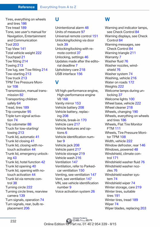
Tires, everything on wheelsand tires 186
Tire tread 189 Tone, see user's manual for
Navigation, Entertainmentand Communication
Tool 203 Top View 141 Total vehicle weight 222 Touchpad 21 Tow fitting 214 Towing 213 Tow lug, see Tow fitting 214 Tow-starting 213 Tow truck 213 TPM Tire Pressure Moni‐
tor 108 Transmission, manual trans‐
mission 82 Transporting children
safely 64 Tread, tires 189 Trip computer 95 Triple turn signal activa‐
tion 74 Trip odometer 88 Truck for tow-starting/
towing 213 Trunk lid, automatic 41 Trunk lid closing 41 Trunk lid, closing with no-
touch activation 44 Trunk lid, emergency unlock‐
ing 43 Trunk lid, hotel function 42 Trunk lid opening 40 Trunk lid, opening with no-
touch activation 44 Trunk lid via remote con‐
trol 38 Turning circle 222 Turning circle lines, rearview
camera 139 Turn signals, operation 74 Turn signals, rear, bulb re‐
placement 206
UUnintentional alarm 48 Units of measure 97 Universal remote control 151 Unlocking/locking via door
lock 39 Unlocking/locking with re‐
mote control 37 Unlocking, settings 46 Updates made after the edito‐
rial deadline 7 Upholstery care 218 USB interface 156
VV8 high-performance engine,
High-performance engineV8 168
Vanity mirror 153 Vehicle battery 208 Vehicle battery, replac‐
ing 208 Vehicle, break-in 170 Vehicle care 217 Vehicle features and op‐
tions 6 Vehicle identification num‐
ber 9 Vehicle jack 208 Vehicle paint 217 Vehicle storage 219 Vehicle wash 216 Ventilation 147 Ventilation, refer to Parked-
car ventilation 150 Venting, see ventilation 147 Vent, see ventilation 147 VIN, see vehicle identification
number 9 Voice activation system 26
WWarning and indicator lamps,
see Check Control 84 Warning displays, see Check
Control 84 Warning messages, see
Check Control 84 Warning triangle 211 Warranty 7 Washer fluid 76 Washer nozzles, wind‐
shield 76 Washer system 74 Washing, vehicle 216 Water on roads 172 Weights 222 Welcome lamps during un‐
locking 37 Welcome lights 100 Wheel base, vehicle 222 Wheel cleaner 218 Wheels, changing 190 Wheels, everything on wheels
and tires 186 Wheels, Flat Tire Monitor
FTM 111 Wheels, Tire Pressure Moni‐
tor TPM 108 Width, vehicle 222 Window defroster, rear 146 Windows, powered 48 Windshield, climate con‐
trol 171 Windshield washer fluid 76 Windshield washer noz‐
zles 76 Windshield washer sys‐
tem 74 Windshield wiper 74 Winter storage, care 219 Winter tires, suitable
tires 191 Winter tires, tread 189 Wiper 74 Wiper blades, replacing 203
Seite 232
Reference Everything from A to Z
232Online Edition for Part no. 01 40 2 954 339 - II/15
Information Provided by:
Wiper fluid 76 Wiper, fold-out position 76 Wiper system 74 Wood, care 218 Word match concept, naviga‐
tion 24 Wrench, see Onboard vehicle
tool kit 203
XXenon headlights, bulb re‐
placement 204
Seite 233
Everything from A to Z Reference
233Online Edition for Part no. 01 40 2 954 339 - II/15
Information Provided by:

Information Provided by:
BMW M
The UltimateDriving Machine®
01 4
0 2
954
339
ue
*BL295433900J*
Online Edition for Part no. 01 40 2 954 339 - II/15
Information Provided by:

![M5ens.lacity.org/clk/rmdroot/clkrmdroot327879435_10242012.pdfM5 ... auto . — --] -](https://static.fdocuments.net/doc/165x107/5e6bc0226a12055c194c5422/-m5ens-m5-auto-a-.jpg)