
The Basics of Motion ControlThe Basics of Motion Control · The Basics of Motion ControlThe Basics...
56
The Basics of Motion Control The Basics of Motion Control The Basics of Motion Control The Basics of Motion Control TM400
Transcript of The Basics of Motion ControlThe Basics of Motion Control · The Basics of Motion ControlThe Basics...
The Basics of Motion ControlThe Basics of Motion ControlThe Basics of Motion ControlThe Basics of Motion Control TM400
not f
or re

2 TM400 The Basics of Motion Control
Prerequisites
Training modules: no prerequisites
Software: no prerequisites
Hardware: no prerequisites not f
or re
The Basics of Motion Control TM400 3
Table of contents
1. INTRODUCTION 4
1.1 Objective 5
2. THE MECHATRONIC DRIVE SOLUTION 6
2.1 The core aspects of mechatronics 8
2.2 The basic requirements for a drive system 10
3. THE COMPONENTS OF A DRIVE SYSTEM 11
3.1 Electrical drives 12
3.2 Position encoders 26
3.3 Power converter 36
4. INTEGRATION IN THE PROCESS 46
4.1 Selecting the technology 46
4.2 Developing the control software 50
5. SUMMARY 53
not f
or re

Introduction
4 TM400 The Basics of Motion Control
1. INTRODUCTION
Nearly every machine or system component today involves positioning
tasks with more or less complex characteristics. The trend is clearly
moving in the direction of mechatronic drive solutions.
Movement procedures that were previously implemented using mechanical
constructions that were sometimes quite elaborate, can now be carried out
with the highest degree of flexibility and efficiency using the latest
technologies from the area of modern motion control.
Fig. 1: The basics of motion control
Uniformity of the drive solution is an important factor in this aspect.
Optimum coordination of the individual components with each other brings
out the true technological strengths. The mechatronic drive network is
integrated into the process as a closed functional unit.
This makes it possible for development to focus mainly on optimizing the
higher-level processes.
This document will describe the fundamental concepts and procedures in a
clear and understandable manner.
The basic functionality of the individual components will also be covered.
Special know-how is not mandatory. not f
or re
Introduction
The Basics of Motion Control TM400 5
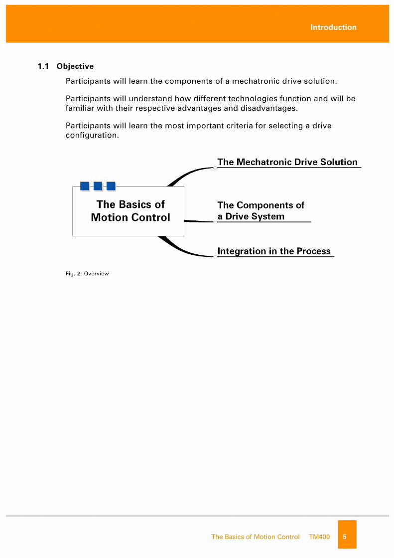
1.1 Objective
Participants will learn the components of a mechatronic drive solution.
Participants will understand how different technologies function and will be
familiar with their respective advantages and disadvantages.
Participants will learn the most important criteria for selecting a drive
configuration.
Fig. 2: Overview
not f
or re

The Mechatronic Drive Solution
6 TM400 The Basics of Motion Control
2. THE MECHATRONIC DRIVE SOLUTION
...Electrical drive system, power transmission system, drive solution, drive
configuration, servo drive, etc.
These (or similar) expressions are used frequently to describe the range of
components in a positioning system. Defining all of this into one single
term is tough to do – but why?
One thing is for certain:
There is a wide range of electrical drive system types. Further more, there
are generally multiple designs of a single component with specific
strengths and weaknesses.
For example, a servo-driven linear motor with high-precision position
determination is required for one type of application, whereas an induction
motor supplied from a frequency inverter is sufficient in another
application.
Fig. 3: Orientation
Therefore, the fundamental questions are:
• What components actually make up a drive system or positioning
system?
• What are the differences between the existing technologies or
variations?
• What are the separate technologies specifically used for?
By approaching each section step-by-step, we will shed some light on
these issues in no time at all. not f
or re

The Mechatronic Drive Solution
The Basics of Motion Control TM400 7
A good place to start is with a simplified diagram, which essentially
applies to all drive systems:
Fig. 4: Basic components
• Power converter
• Electric motor
• Mechanical gear
• Mechanical process
The power converter takes electrical energy from the mains and turns it
into a suitable "form" for supplying the electric motor. The motor then
converts the electrical energy into kinetic energy, thereby putting the
mechanical system into motion (via a mechanical gear if necessary).
We will add to this basic scheme step-by-step as we work through the
following sections. We will be concentrating on the functionality of the
individual components and their properties in the complete system.
But let's first go back one step and take a quick look at a topic that involves
all aspects of modern drive technology. We are talking about the area of
mechatronics.
not f
or re

The Mechatronic Drive Solution
8 TM400 The Basics of Motion Control
2.1 The core aspects of mechatronics
The area of mechatronics deals with the interaction of mechanic, electronic
and information-oriented systems.
Fig. 5: Mechatronics
In mechatronics, the separation between the areas of mechanics,
electricity, electronics and information technology is put aside. The system
is viewed as a single functional unit.
The main goal is the processing of all information for usage in all of these
areas.
Fig. 6: Communication throughout the whole system
This is exactly the challenge when designing and setting up an electrical
drive system.
In addition to the visible components such as motor or power converter
(hardware), complex control loops, algorithms and a number of
communication procedures play a decisive role in automated positioning . not f
or re
The Mechatronic Drive Solution
The Basics of Motion Control TM400 9
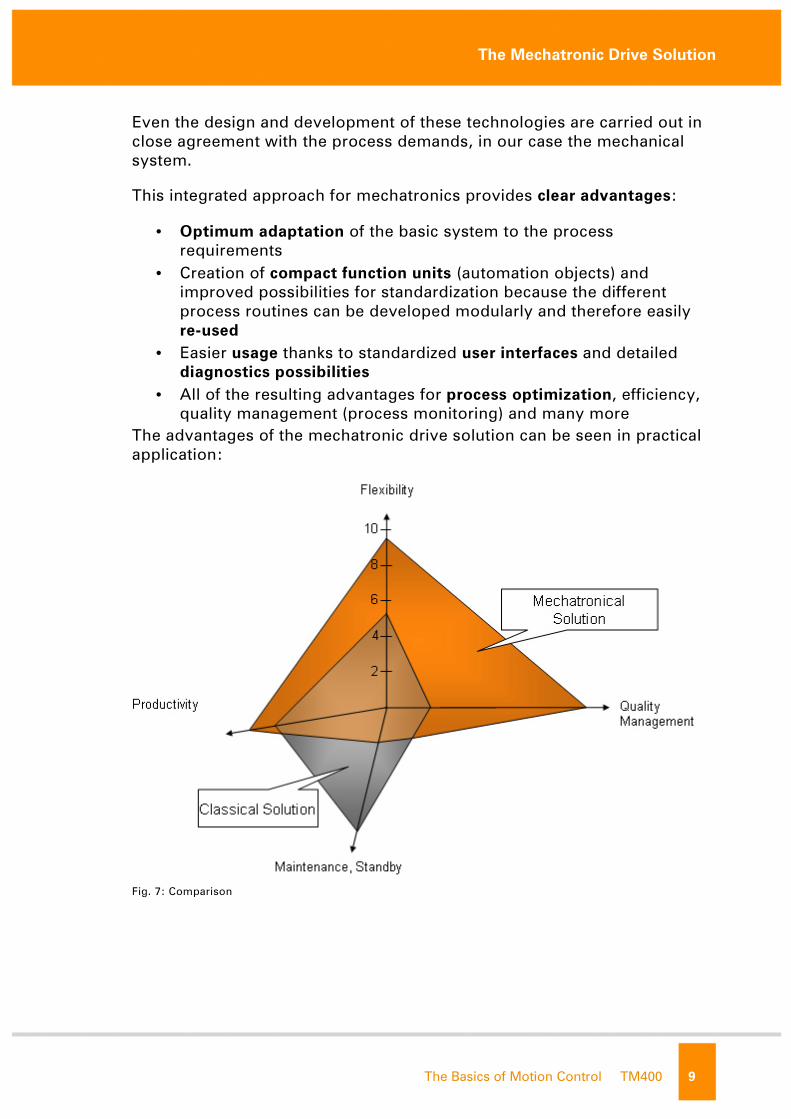
Even the design and development of these technologies are carried out in
close agreement with the process demands, in our case the mechanical
system.
This integrated approach for mechatronics provides clear advantages:
• Optimum adaptation of the basic system to the process
requirements
• Creation of compact function units (automation objects) and
improved possibilities for standardization because the different
process routines can be developed modularly and therefore easily
re-used
• Easier usage thanks to standardized user interfaces and detailed
diagnostics possibilities
• All of the resulting advantages for process optimization, efficiency,
quality management (process monitoring) and many more
The advantages of the mechatronic drive solution can be seen in practical
application:
Fig. 7: Comparison not f
or re

The Mechatronic Drive Solution
10 TM400 The Basics of Motion Control
2.2 The basic requirements for a drive system
What properties characterize a drive system?
An important requirement of the system is for it to be highly dynamic.
The term "dynamics" (from the Greek dynamiké – relating to power or
energy) describes general force, propulsion or force adjusted to change.
This will be used to summarize development over time.
In practice, it is often necessary to achieve the following in the shortest
amount of time possible:
• quickly reaching a certain speed or
• quickly reaching an exact position
Therefore, the drive system must be able to position the connected
mechanics exactly according to specification and to apply the highest
amount of force without "getting out of whack".
This characteristic is then applied directly to the machine's productivity
(increased clock rate, etc.).
In many applications, positioning precision is also a decisive factor for the
suitability of a drive system. In addition to the dynamic properties, the
drive must also be able to accept exact positions and to maintain these
positions with the corresponding force (e.g. with constant torque load from
hanging loads).
Choosing the electric motor is not the only decisive factor. Sophisticated
measurement systems and control algorithms also play a major role in
accomplishing these tasks.
High demands can only be met with compact interaction of all
components in the system.
Note:
Definition of servo drive:
Servo drives are drive systems that feature dynamic and accurate
behavior able to handle overloading over a wide speed range.
not f
or re
The Components of a Drive System
The Basics of Motion Control TM400 11
3. THE COMPONENTS OF A DRIVE SYSTEM
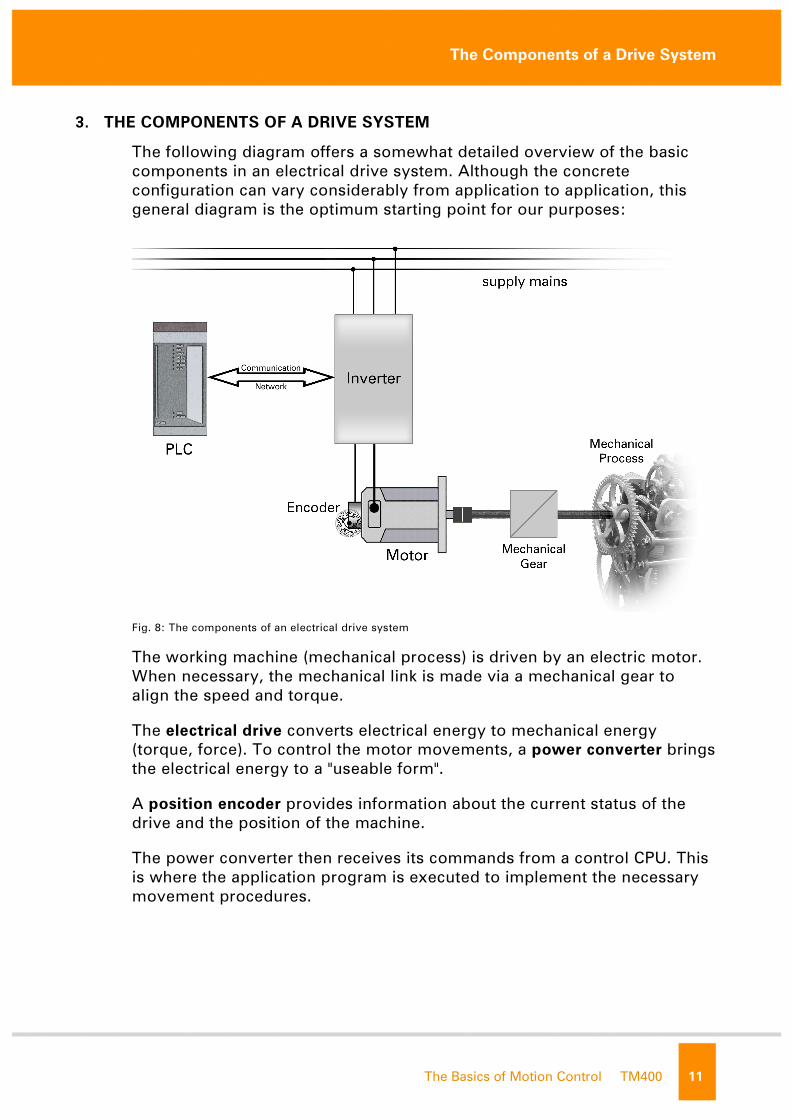
The following diagram offers a somewhat detailed overview of the basic
components in an electrical drive system. Although the concrete
configuration can vary considerably from application to application, this
general diagram is the optimum starting point for our purposes:
Fig. 8: The components of an electrical drive system
The working machine (mechanical process) is driven by an electric motor.
When necessary, the mechanical link is made via a mechanical gear to
align the speed and torque.
The electrical drive converts electrical energy to mechanical energy
(torque, force). To control the motor movements, a power converter brings
the electrical energy to a "useable form".
A position encoder provides information about the current status of the
drive and the position of the machine.
The power converter then receives its commands from a control CPU. This
is where the application program is executed to implement the necessary
movement procedures.
not f
or re

The Components of a Drive System
12 TM400 The Basics of Motion Control
3.1 Electrical drives
Since the initial development of electromechanical energy forms at the
start of the 19th century, three different types of motors have been
established which differ in structure and functionality:
• DC motors
• Synchronous motors
• Induction motors
There are many variations of these basic types e.g.: linear motors, torque
motors, stepper motors, reluctance motors, etc.
We will now take a brief look at the structure of the individual motor types
and become familiar with their special characteristics.
One of the three types, together with the possibilities of modern inverter
technology, will prove to be specially suited for precise and dynamic
positioning procedures.
3.1.1 The basic principle of electrical drives
Lorentz force is the basic physical principle for the function of electrical
drives:
A conductor with electrical current located in a magnetic field is subject to
a certain force.
Note:
Throughout the course of this document, we will get to know the two
power converter types; servo drive and frequency converters. The
servo drive is the considerably more "intelligent" power converter
design with its ability to control highly dynamic and precisely
positioned movements.
Therefore, we will spend the majority of our time with this type of
power converter and will from now on be talking about "positioning
systems".
not f
or re
The Components of a Drive System
The Basics of Motion Control TM400 13
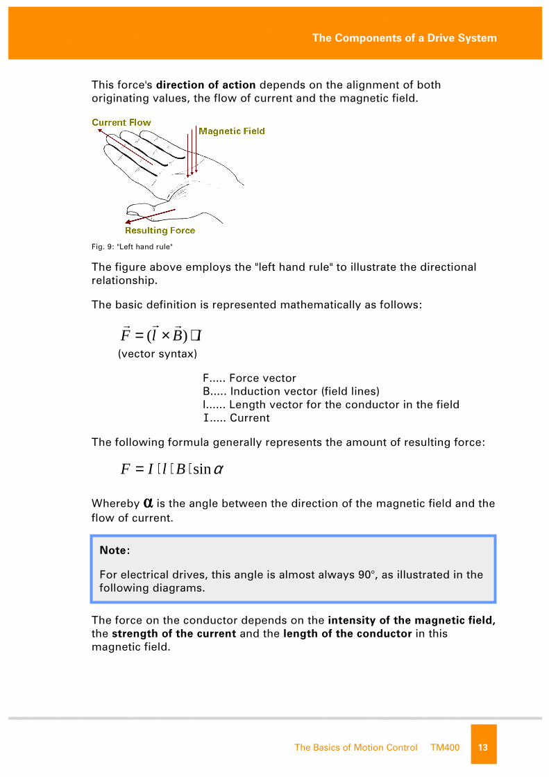
This force's direction of action depends on the alignment of both
originating values, the flow of current and the magnetic field.
Fig. 9: "Left hand rule"
The figure above employs the "left hand rule" to illustrate the directional
relationship.
The basic definition is represented mathematically as follows:
IBlF ⋅×= )(rrr
(vector syntax)
F..... Force vector
B..... Induction vector (field lines)
l...... Length vector for the conductor in the field
I..... Current
The following formula generally represents the amount of resulting force:
αsin⋅⋅⋅= BlIF
Whereby ���� is the angle between the direction of the magnetic field and the
flow of current.
The force on the conductor depends on the intensity of the magnetic field,
the strength of the current and the length of the conductor in this
magnetic field.
Note:
For electrical drives, this angle is almost always 90°, as illustrated in the
following diagrams.
not f
or re

The Components of a Drive System
14 TM400 The Basics of Motion Control
The following diagrams illustrate the principle of applying this force in a
rotational movement:
Fig. 10: Coil conducting current in the magnetic field
A pivoting coil conducting current is located in a magnetic field. A flow of
current in the conductor creates mechanical force in the coil sections
diagonal to the direction of the magnetic field – these sections are drawn
vertical to the image plane in the diagram.
These forces affect the rotational range of the pivoting coil. The torque for
the resulting rotation is represented as follows:
αsin2 ⋅⋅⋅= rFM
starting from this position, the system would assume a "rest position" after
a defined amount of time:
Fig. 11: Rest position
There are two ways now to sustain the rotational movement:
• Reversal of the direction of current flow not f
or re
The Components of a Drive System
The Basics of Motion Control TM400 15
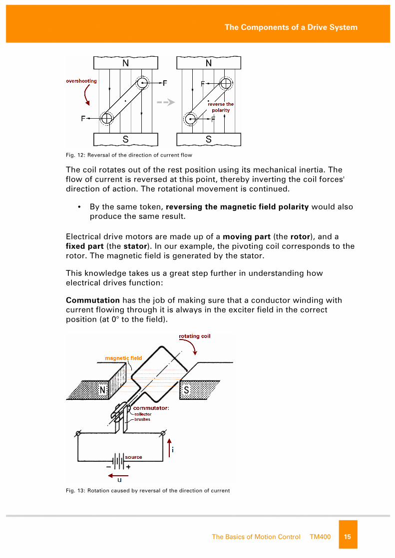
Fig. 12: Reversal of the direction of current flow
The coil rotates out of the rest position using its mechanical inertia. The
flow of current is reversed at this point, thereby inverting the coil forces'
direction of action. The rotational movement is continued.
• By the same token, reversing the magnetic field polarity would also
produce the same result.
Electrical drive motors are made up of a moving part (the rotor), and a
fixed part (the stator). In our example, the pivoting coil corresponds to the
rotor. The magnetic field is generated by the stator.
This knowledge takes us a great step further in understanding how
electrical drives function:
Commutation has the job of making sure that a conductor winding with
current flowing through it is always in the exciter field in the correct
position (at 0° to the field).
Fig. 13: Rotation caused by reversal of the direction of current
not f
or re
The Components of a Drive System
16 TM400 The Basics of Motion Control
On a DC motor this is achieved using a collector and brushes for
establishing contact, as shown in the above arrangement. This is also
known as a mechanical commutation.
The wear of the mechanical elements in the commutator (collector, carbon
brushes) and the resulting maintenance that is required represent a
disadvantage of the collector motor.
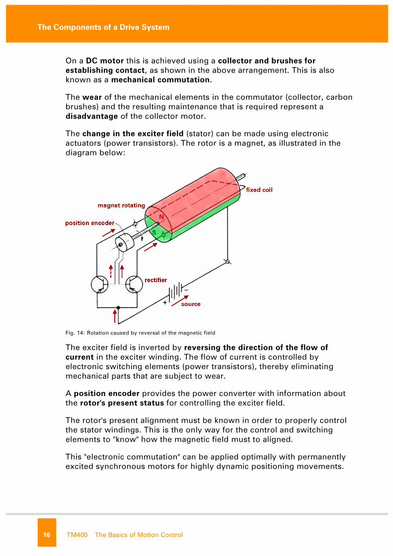
The change in the exciter field (stator) can be made using electronic
actuators (power transistors). The rotor is a magnet, as illustrated in the
diagram below:
Fig. 14: Rotation caused by reversal of the magnetic field
The exciter field is inverted by reversing the direction of the flow of
current in the exciter winding. The flow of current is controlled by
electronic switching elements (power transistors), thereby eliminating
mechanical parts that are subject to wear.
A position encoder provides the power converter with information about
the rotor's present status for controlling the exciter field.
The rotor's present alignment must be known in order to properly control
the stator windings. This is the only way for the control and switching
elements to "know" how the magnetic field must to aligned.
This "electronic commutation" can be applied optimally with permanently
excited synchronous motors for highly dynamic positioning movements. not f
or re
The Components of a Drive System
The Basics of Motion Control TM400 17
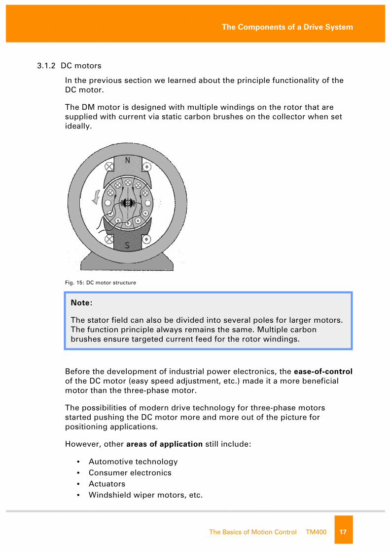
3.1.2 DC motors
In the previous section we learned about the principle functionality of the
DC motor.
The DM motor is designed with multiple windings on the rotor that are
supplied with current via static carbon brushes on the collector when set
ideally.
Fig. 15: DC motor structure
Before the development of industrial power electronics, the ease-of-control
of the DC motor (easy speed adjustment, etc.) made it a more beneficial
motor than the three-phase motor.
The possibilities of modern drive technology for three-phase motors
started pushing the DC motor more and more out of the picture for
positioning applications.
However, other areas of application still include:
• Automotive technology
• Consumer electronics
• Actuators
• Windshield wiper motors, etc.
Note:
The stator field can also be divided into several poles for larger motors.
The function principle always remains the same. Multiple carbon
brushes ensure targeted current feed for the rotor windings.
not f
or re
The Components of a Drive System
18 TM400 The Basics of Motion Control
3.1.3 Rotating field motors (AC motors)
Developments in the area of electronics as well as materials have lead to a
shift from the DC motor to the three-phase motor in the drive systems.
Even in servo systems, which used to be used solely in DC technology, a
strong tendency has been seen towards three-phase synchronous motors.
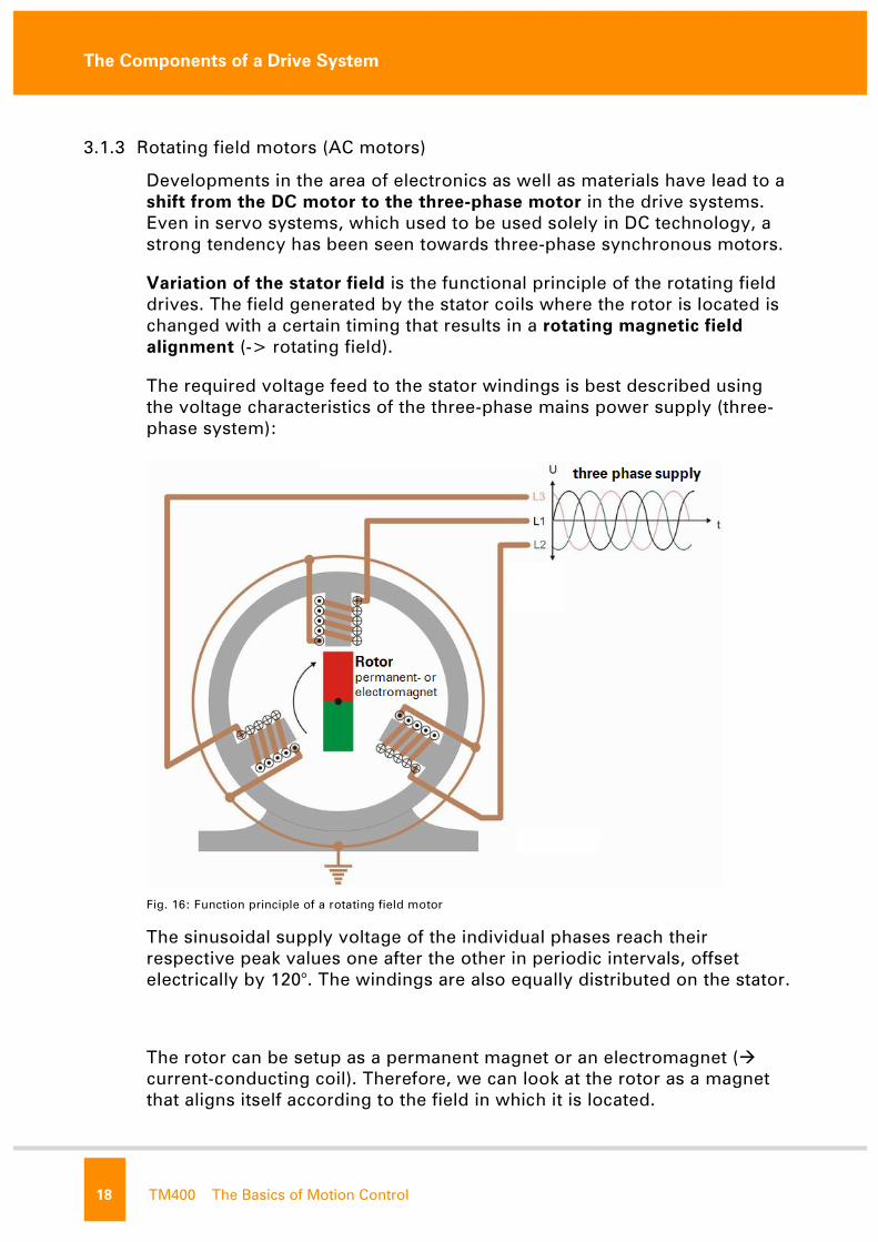
Variation of the stator field is the functional principle of the rotating field
drives. The field generated by the stator coils where the rotor is located is
changed with a certain timing that results in a rotating magnetic field
alignment (-> rotating field).
The required voltage feed to the stator windings is best described using
the voltage characteristics of the three-phase mains power supply (three-
phase system):
Fig. 16: Function principle of a rotating field motor
The sinusoidal supply voltage of the individual phases reach their
respective peak values one after the other in periodic intervals, offset
electrically by 120°. The windings are also equally distributed on the stator.
The rotor can be setup as a permanent magnet or an electromagnet (�
current-conducting coil). Therefore, we can look at the rotor as a magnet
that aligns itself according to the field in which it is located.
not f
or re
The Components of a Drive System
The Basics of Motion Control TM400 19
The maximum supply voltage and therefore the maximum of the stator
field influence moves in a circle around the stator circumference. The
magnetic field vector made up of the individual coil fields rotates in the
stator.
The rotor is essentially "passed" between the individual stator windings.
The manner in which the magnetic field occurs in the rotor is different in
the two types of three-phase motor:
• Induction motors
• Synchronous motor
Furthermore, special designs of the rotating field motors are become more
and more common. Direct drives are steadily gaining importance because
of their special characteristics for automated positioning.
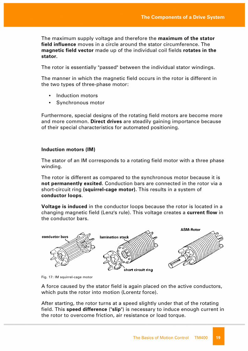
Induction motors (IM)
The stator of an IM corresponds to a rotating field motor with a three phase
winding.
The rotor is different as compared to the synchronous motor because it is
not permanently excited. Conduction bars are connected in the rotor via a
short-circuit ring (squirrel-cage motor). This results in a system of
conductor loops.
Voltage is induced in the conductor loops because the rotor is located in a
changing magnetic field (Lenz's rule). This voltage creates a current flow in
the conductor bars.
Fig. 17: IM squirrel-cage motor
A force caused by the stator field is again placed on the active conductors,
which puts the rotor into motion (Lorentz force).
After starting, the rotor turns at a speed slightly under that of the rotating
field. This speed difference ("slip") is necessary to induce enough current in
the rotor to overcome friction, air resistance or load torque.
not f
or re
The Components of a Drive System
20 TM400 The Basics of Motion Control
The rotor can never reach the speed of the rotating field, therefore the
movement is asynchronous, resulting in the term asynchronous motor
(induction motor).
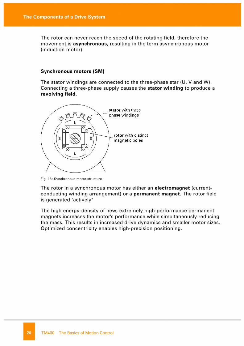
Synchronous motors (SM)
The stator windings are connected to the three-phase star (U, V and W).
Connecting a three-phase supply causes the stator winding to produce a
revolving field.
Fig. 18: Synchronous motor structure
The rotor in a synchronous motor has either an electromagnet (current-
conducting winding arrangement) or a permanent magnet. The rotor field
is generated "actively"
The high energy-density of new, extremely high-performance permanent
magnets increases the motor's performance while simultaneously reducing
the mass. This results in increased drive dynamics and smaller motor sizes.
Optimized concentricity enables high-precision positioning.
not f
or re
The Components of a Drive System
The Basics of Motion Control TM400 21
Direct drive systems
Direct drives reduce the amount of mechanical transfer elements (e.g. a
gear) needed between the motor and working machine.
The special motors developed for this purpose feature high torque
(torque/sector motor) and high thrust (linear motor). Let's take a brief look
at two common types of direct drives:
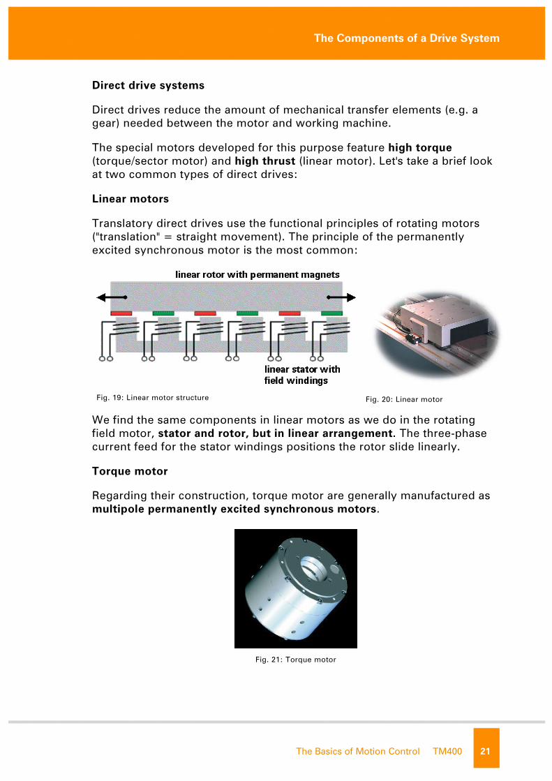
Linear motors
Translatory direct drives use the functional principles of rotating motors
("translation" = straight movement). The principle of the permanently
excited synchronous motor is the most common:
Fig. 19: Linear motor structure
Fig. 20: Linear motor
We find the same components in linear motors as we do in the rotating
field motor, stator and rotor, but in linear arrangement. The three-phase
current feed for the stator windings positions the rotor slide linearly.
Torque motor
Regarding their construction, torque motor are generally manufactured as
multipole permanently excited synchronous motors.
Fig. 21: Torque motor not f
or re
The Components of a Drive System
22 TM400 The Basics of Motion Control
The torque motor is often built with a rotor molded into a hollow shaft. This
enables the mechanical connection for transferring high torque forces. The
torque motor can be optimized to the working machine.
The benefits in detail:
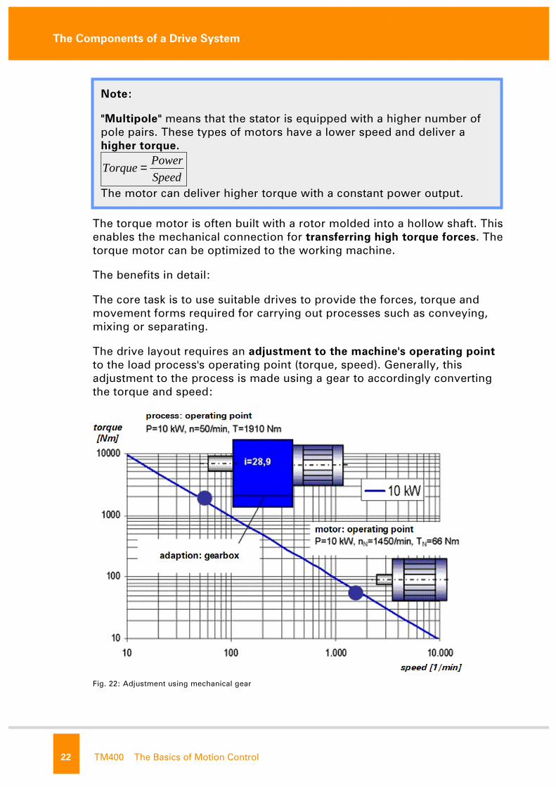
The core task is to use suitable drives to provide the forces, torque and
movement forms required for carrying out processes such as conveying,
mixing or separating.
The drive layout requires an adjustment to the machine's operating point
to the load process's operating point (torque, speed). Generally, this
adjustment to the process is made using a gear to accordingly converting
the torque and speed:
Fig. 22: Adjustment using mechanical gear
Note:
"Multipole" means that the stator is equipped with a higher number of
pole pairs. These types of motors have a lower speed and deliver a
higher torque.
Speed
PowerTorque =
The motor can deliver higher torque with a constant power output.
not f
or re
The Components of a Drive System
The Basics of Motion Control TM400 23
A gear is not necessary when the process operating point coincides with
that of the machine. The motor – in this case the electric motor – becomes
the direct drive.
A direct drive has zero-play because mechanical transfer elements are not
used.
System values such as current, force/torque and speed/revolution can be
determined directly and integrated in a control concept. In addition to
improving the positioning accuracy, this also increases control of this
drive.
General characteristics of the direct drive:
• Low moment of inertia
• Precision (zero-play) paired with dynamics
• Elimination of parts that are subject to wear (gear)
• Small installation dimensions
• Large hollow shaft diameter possible
The high power density in direct drives can cause significant heating in the
drive. Therefore, they are often equipped with water or air cooling systems,
which is not always necessary in comparable drives that use mechanical
power conversion.
Note:
The term "power density" refers to a drive's peak power (in this case,
the mechanical power) in relation to its mass and size.
Compared with a drive technology that has larger power density, a
drive with smaller power density, designed for the same peak power,
will be smaller in size and dimensions.
not f
or re

The Components of a Drive System
24 TM400 The Basics of Motion Control
3.1.4 Comparison of motor types
Development over the past few years has resulted in a number of
innovations and improvements in the area of microprocessors and power
electronic switching elements.
Nowadays, it is possible to use intelligent power converters for targeted
control of the stator coils allowing the stator field to be rotated or
dynamically placed with variable frequency ("independent of the mains").
These conditions now make it possible to utilize the major advantages of
three-phase drives:
• Maintenance-free operation due to the elimination of mechanical
commutation
• Better cooling characteristics
• Robust design
• Synchronous motors are the best choice to meet highly dynamic
movement criteria.
Fig. 23: Comparison of motor types
This comparison clearly shows the advantages of the permanently excited
synchronous motors as opposed to the DC motor.
not f
or re

The Components of a Drive System
The Basics of Motion Control TM400 25
The induction motor is also considerably less effective than the
permanently excited synchronous motor. In principle, the induction motor
can achieve relatively high dynamic properties. However, much more
complex control systems are needed than for the synchronous motor to do
this. This motor type is well-suited to be operated by a frequency inverter
(rotating field specification without reference to rotor position) and is
typically used in this area.
The direct drive characteristics, usually a special design of the permanently
excited synchronous motor, were already covered in the previous section.
not f
or re

The Components of a Drive System
26 TM400 The Basics of Motion Control
3.2 Position encoders
The position encoder is an important part of the drive system. As the name
implies, it enables accurate determination of the position or status of a
mechanical element. The speed is then derived from this information.
Fig. 24: Position measurement
The position system
Clearly, the drive position is the fundamental information used when
controlling a positioning process.
The drive system, and therefore the machine's mechanics, can only be
"sent" to a defined position by using the following methods to introduce a
unique positioning system:
• Defining the position of the position zero-point
• Dividing the encoder revolution into a specific number of position
units
"... move to absolute position 3000"
Note:
In principle, a position encoder is not required for operating a frequency
converter. Encoders will, in some applications, be used for position
measurement, (so-called external encoders), but do not have direct
contact with the frequency converter.
not f
or re
The Components of a Drive System
The Basics of Motion Control TM400 27
"... 290 units to the right of the present position ..."
The position encoder as measuring element
The position encoder sends the actual position and speed, thereby
functioning as a measurement tool in the process.
Therefore, the position encoder plays multiple roles in a servo system:
• The position encoder provides the servo drive with the information
about the current position and speed of the drive. As we will see
later, the stator field of the electrical drive is specifically controlled
by the servo drive (electronic commutation). This control makes it
possible to bring the drive rotor to a defined alignment or to
dynamically put it in motion.
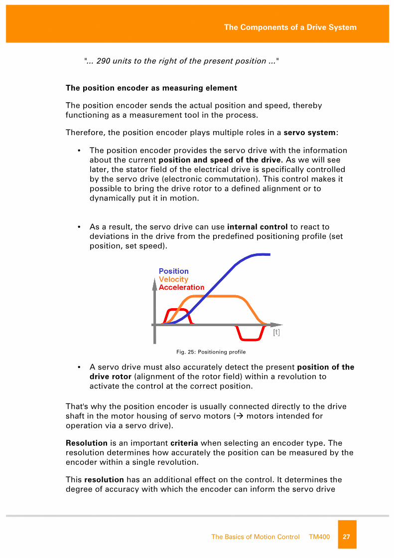
• As a result, the servo drive can use internal control to react to
deviations in the drive from the predefined positioning profile (set
position, set speed).
Fig. 25: Positioning profile
• A servo drive must also accurately detect the present position of the
drive rotor (alignment of the rotor field) within a revolution to
activate the control at the correct position.
That's why the position encoder is usually connected directly to the drive
shaft in the motor housing of servo motors (� motors intended for
operation via a servo drive).
Resolution is an important criteria when selecting an encoder type. The
resolution determines how accurately the position can be measured by the
encoder within a single revolution.
This resolution has an additional effect on the control. It determines the
degree of accuracy with which the encoder can inform the servo drive
not f
or re
The Components of a Drive System
28 TM400 The Basics of Motion Control
about control deviations. A high encoder resolution improves the control
quality decisively.
Additional characteristics of encoder systems will be discussed together
with the individual encoder types.
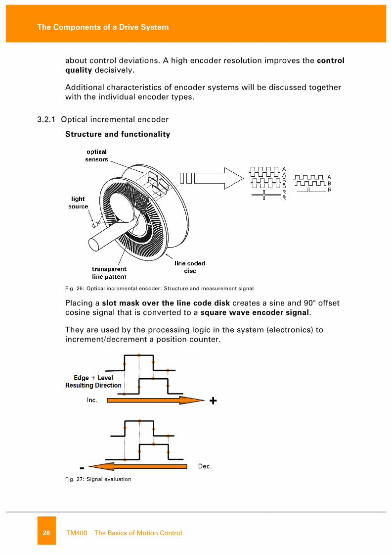
3.2.1 Optical incremental encoder
Structure and functionality
Fig. 26: Optical incremental encoder: Structure and measurement signal
Placing a slot mask over the line code disk creates a sine and 90° offset
cosine signal that is converted to a square wave encoder signal.
They are used by the processing logic in the system (electronics) to
increment/decrement a position counter.
Fig. 27: Signal evaluation
not f
or re
The Components of a Drive System
The Basics of Motion Control TM400 29
When using an incremental encoder, the position of the mechanics (�
encoder position) cannot be concluded right away due to the encoder
information. Only the "increment" is recognized in positive or negative
direction as position information.
The incremental encoder cannot determine the position of the encoder
within one revolution.
An additional reference track provides an "improvised" indication for
determining the position within one revolution. In order to create a
relationship between the counter and the current position, a homing
procedure has to be carried out.
The resolution of the incremental encoder depends on the number of lines,
the type of evaluation (1x, 2x, 4x) and the maximum input frequency of the
processing logic.
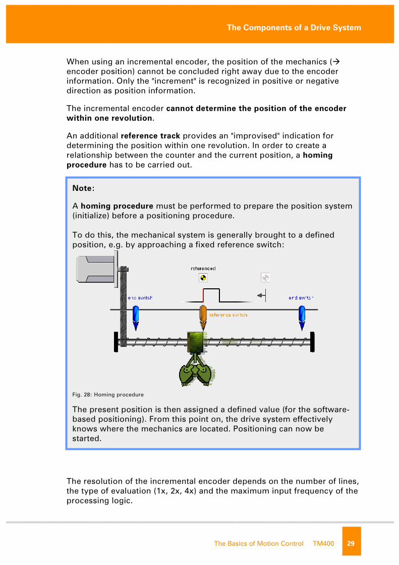
Note:
A homing procedure must be performed to prepare the position system
(initialize) before a positioning procedure.
To do this, the mechanical system is generally brought to a defined
position, e.g. by approaching a fixed reference switch:
Fig. 28: Homing procedure
The present position is then assigned a defined value (for the software-
based positioning). From this point on, the drive system effectively
knows where the mechanics are located. Positioning can now be
started. not f
or re
The Components of a Drive System
30 TM400 The Basics of Motion Control
The optical incremental encoder has a very high resolution (several million
increments possible per revolution) and features high-speed evaluation.
This is clearly an advantage for controlling the servo drive (speed, position
etc.). Information about deviation of the present values from the set values
is very quickly available on the servo drive. Reaction is possible within
minimal dwell time.
3.2.2 Resolver – inductive absolute value encoder
The military designed a very robust encoder with simple construction – the
resolver.
Structure and functionality
The resolver works on the principle of a rotary transformer. In a rotary
transformer, the rotor consists of a coil (winding), which together with the
stator winding, makes up a transformer.
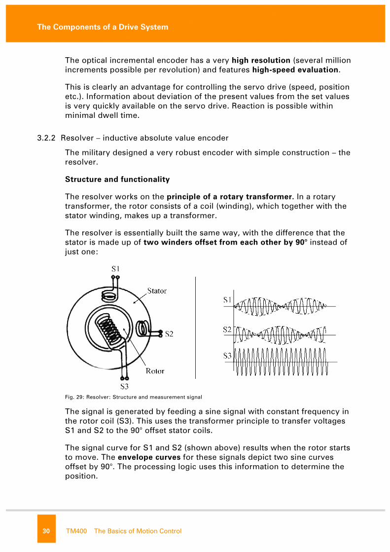
The resolver is essentially built the same way, with the difference that the
stator is made up of two winders offset from each other by 90° instead of
just one:
Fig. 29: Resolver: Structure and measurement signal
The signal is generated by feeding a sine signal with constant frequency in
the rotor coil (S3). This uses the transformer principle to transfer voltages
S1 and S2 to the 90° offset stator coils.
The signal curve for S1 and S2 (shown above) results when the rotor starts
to move. The envelope curves for these signals depict two sine curves
offset by 90°. The processing logic uses this information to determine the
position. not f
or re
The Components of a Drive System
The Basics of Motion Control TM400 31
If the movement area for the axis is within one encoder revolution, each
encoder value corresponds to a unique position (homing is not necessary).
The output signal is repeated on the resolver (the position information from
the envelope curves) with each new revolution. If for example, you
deactivated the drive system and manually turned the motor shaft 360°, the
system would have no chance of detecting this manipulation.
If the movement range of the machine exceeds this one revolution, then a
homing procedure must be performed on the resolver (in most cases) after
restarting the system.
The resolution of the resolver depends on the processing logic and the
frequency of the supply for the rotor coil (4096/16384 increments).
A specific amount of time passes before the processing logic sends the
corresponding value about the present position. This means an additional
dead time for the control loop. This dead time affects the control quality.
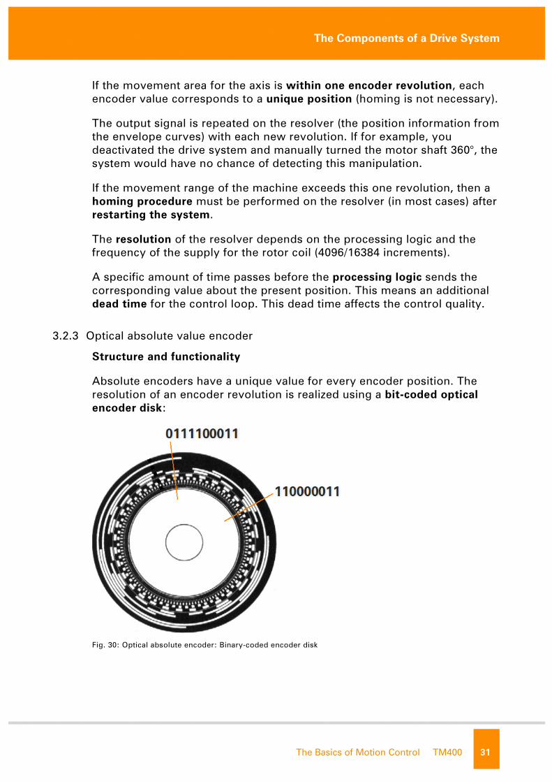
3.2.3 Optical absolute value encoder
Structure and functionality
Absolute encoders have a unique value for every encoder position. The
resolution of an encoder revolution is realized using a bit-coded optical
encoder disk:
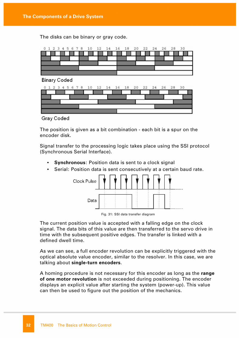
Fig. 30: Optical absolute encoder: Binary-coded encoder disk
not f
or re
The Components of a Drive System
32 TM400 The Basics of Motion Control
The disks can be binary or gray code.
The position is given as a bit combination - each bit is a spur on the
encoder disk.
Signal transfer to the processing logic takes place using the SSI protocol
(Synchronous Serial Interface).
• Synchronous: Position data is sent to a clock signal
• Serial: Position data is sent consecutively at a certain baud rate.
Fig. 31: SSI data transfer diagram
The current position value is accepted with a falling edge on the clock
signal. The data bits of this value are then transferred to the servo drive in
time with the subsequent positive edges. The transfer is linked with a
defined dwell time.
As we can see, a full encoder revolution can be explicitly triggered with the
optical absolute value encoder, similar to the resolver. In this case, we are
talking about single-turn encoders.
A homing procedure is not necessary for this encoder as long as the range
of one motor revolution is not exceeded during positioning. The encoder
displays an explicit value after starting the system (power-up). This value
can then be used to figure out the position of the mechanics. not f
or re

The Components of a Drive System
The Basics of Motion Control TM400 33
The multi-turn encoder is the expanded version of the single-turn encoder.
The explicit resolution of an encoder revolution (single-turn) is expanded
with a counting mechanism, which determines the number of complete
revolutions.
This information is used to stretch the explicitly defined position
measurement range to a specific number of revolutions (typically 4096
revolutions).
A homing procedure is no longer necessary when using a multi-turn
encoder. The current machine position can be figured out immediately
once the position offset has been determined one time.
This counting mechanism is implemented either with an additional
mechanical transfer gear or an electronic logic.
Note:
The position offset is the difference between the actual internal
encoder position and the machine position.
For example: The mechanics are in the zero position, the software-
based position should be set to zero there (position = 0), present
encoder position value = 56343, (i.e. offset= 56343):
Fig. 32: Encoder offset
This offset can be used from any position to figure out the position of
the mechanics.
not f
or re
The Components of a Drive System
34 TM400 The Basics of Motion Control
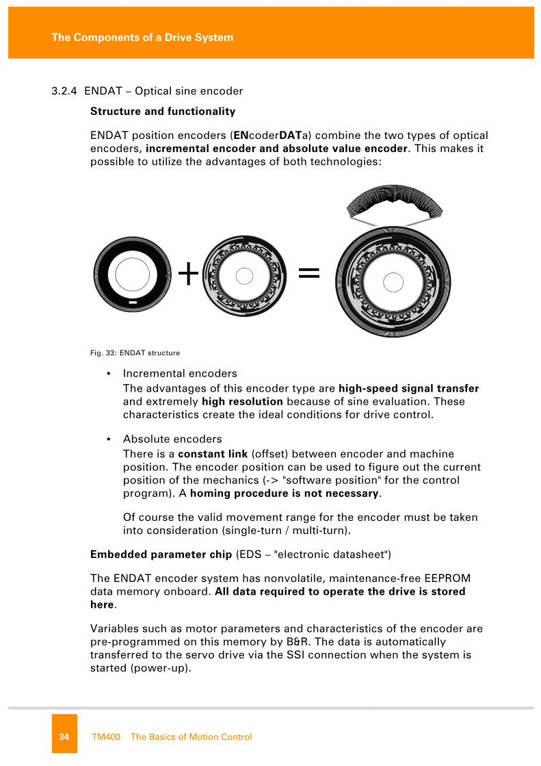
3.2.4 ENDAT – Optical sine encoder
Structure and functionality
ENDAT position encoders (ENcoderDATa) combine the two types of optical
encoders, incremental encoder and absolute value encoder. This makes it
possible to utilize the advantages of both technologies:
Fig. 33: ENDAT structure
• Incremental encoders
The advantages of this encoder type are high-speed signal transfer
and extremely high resolution because of sine evaluation. These
characteristics create the ideal conditions for drive control.
• Absolute encoders
There is a constant link (offset) between encoder and machine
position. The encoder position can be used to figure out the current
position of the mechanics (-> "software position" for the control
program). A homing procedure is not necessary.
Of course the valid movement range for the encoder must be taken
into consideration (single-turn / multi-turn).
Embedded parameter chip (EDS – "electronic datasheet")
The ENDAT encoder system has nonvolatile, maintenance-free EEPROM
data memory onboard. All data required to operate the drive is stored
here.
Variables such as motor parameters and characteristics of the encoder are
pre-programmed on this memory by B&R. The data is automatically
transferred to the servo drive via the SSI connection when the system is
started (power-up).
not f
or re
The Components of a Drive System
The Basics of Motion Control TM400 35
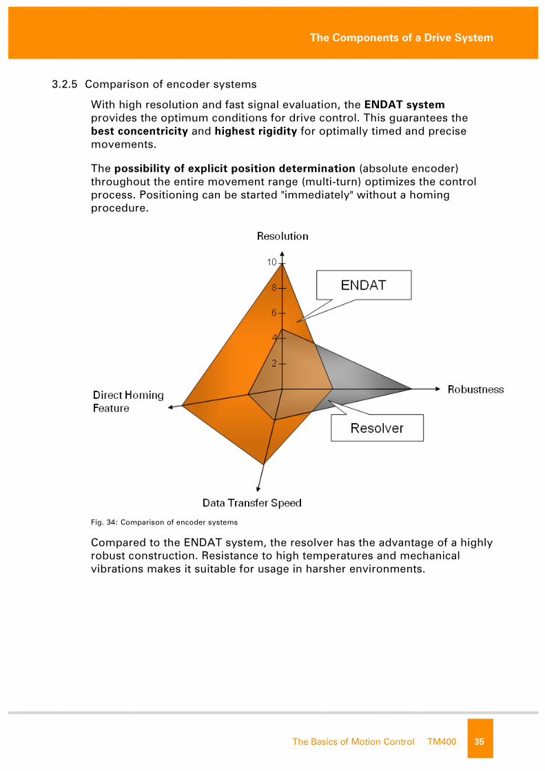
3.2.5 Comparison of encoder systems
With high resolution and fast signal evaluation, the ENDAT system
provides the optimum conditions for drive control. This guarantees the
best concentricity and highest rigidity for optimally timed and precise
movements.
The possibility of explicit position determination (absolute encoder)
throughout the entire movement range (multi-turn) optimizes the control
process. Positioning can be started "immediately" without a homing
procedure.
Fig. 34: Comparison of encoder systems
Compared to the ENDAT system, the resolver has the advantage of a highly
robust construction. Resistance to high temperatures and mechanical
vibrations makes it suitable for usage in harsher environments.
not f
or re
The Components of a Drive System
36 TM400 The Basics of Motion Control
3.3 Power converter
General definition
A power converter's job is to convert electrical energy from a mains power
supply for the operation of electrical drives.
Why is this conversion necessary?
As we now know, the stator field for rotating field motors can be "set"
using the voltage supply of the stator windings. The alignment and
intensity of the magnetic field in the stator result from the respective
winding voltages.
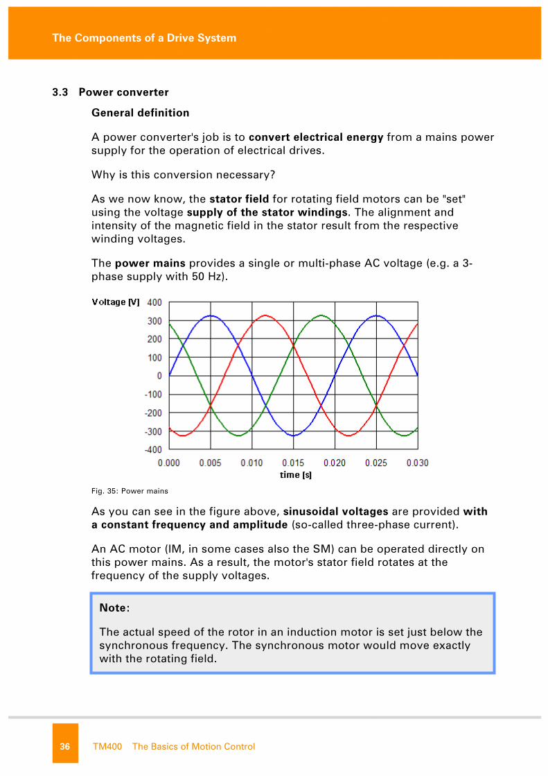
The power mains provides a single or multi-phase AC voltage (e.g. a 3-
phase supply with 50 Hz).
Fig. 35: Power mains
As you can see in the figure above, sinusoidal voltages are provided with
a constant frequency and amplitude (so-called three-phase current).
An AC motor (IM, in some cases also the SM) can be operated directly on
this power mains. As a result, the motor's stator field rotates at the
frequency of the supply voltages.
Note:
The actual speed of the rotor in an induction motor is set just below the
synchronous frequency. The synchronous motor would move exactly
with the rotating field. not f
or re

The Components of a Drive System
The Basics of Motion Control TM400 37
A power converter is now needed to specifically control the characteristic
of the stator voltages for positioning. The converter takes electrical energy
from the mains supply and passes on the voltage characteristics required
for positioning to the motor.
In the following section, we will break the power converter down into
general, easily-understandable parts.
There are considerable differences between the two main types of power
converters in electrical drive technology, which will be looked at in detail at
the end:
• Frequency converter and
• Servo drives
3.3.1 Function principle
The principle behind the power electronics is generally the same for
frequency converters and servo drives. It consists of three parts:
Fig. 36: Power conversion principle - power electronics
• Rectifier, in this case - bridge rectifier
• DC bus, in this case - voltage DC bus
• Power inverter, in this case - 6 pulse inverter
not f
or re
The Components of a Drive System
38 TM400 The Basics of Motion Control
The bridge rectifier generates a DC voltage from the sinusoidal AC voltage
of the power mains.
This DC voltage is stored in the so-called DC bus. The DC bus capacitor
takes over storage of the electrical energy. In this manner, the DC bus
becomes a sort of "energy pool" from which the downstream power
inverter can draw energy.
The voltage required to control the motor is clocked from the DC bus
voltage.
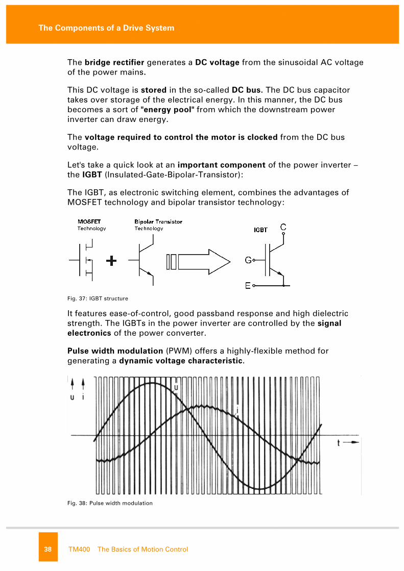
Let's take a quick look at an important component of the power inverter –
the IGBT (Insulated-Gate-Bipolar-Transistor):
The IGBT, as electronic switching element, combines the advantages of
MOSFET technology and bipolar transistor technology:
Fig. 37: IGBT structure
It features ease-of-control, good passband response and high dielectric
strength. The IGBTs in the power inverter are controlled by the signal
electronics of the power converter.
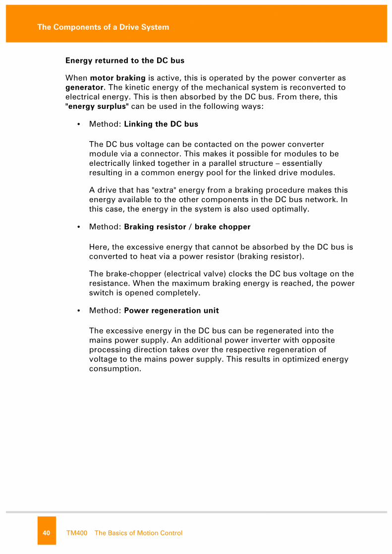
Pulse width modulation (PWM) offers a highly-flexible method for
generating a dynamic voltage characteristic.
Fig. 38: Pulse width modulation
not f
or re

The Components of a Drive System
The Basics of Motion Control TM400 39
3.3.2 Other components
We will now add a few more important function units of the power
converter.
Fig. 40: Power converter structure
Line filters
In some operating conditions, the power converter can cause disturbance
signals in the mains power supply (rectifier and power inverter). A line
filter is integrated to avoid interfering with the mains supply and
influencing other components on the supply network.
Note:
Closing or opening the voltage valve within a constant period with the
pulse width modulation generates a specific effective value on the
output. The longer the valve is open within a cycle, the larger the
effective output value of this period.
Fig. 39: Pulse width modulation principle
The clock frequency is a decisive factor for the quality of the effective
value generation.
not f
or re
The Components of a Drive System
40 TM400 The Basics of Motion Control
Energy returned to the DC bus
When motor braking is active, this is operated by the power converter as
generator. The kinetic energy of the mechanical system is reconverted to
electrical energy. This is then absorbed by the DC bus. From there, this
"energy surplus" can be used in the following ways:
• Method: Linking the DC bus
The DC bus voltage can be contacted on the power converter
module via a connector. This makes it possible for modules to be
electrically linked together in a parallel structure – essentially
resulting in a common energy pool for the linked drive modules.
A drive that has "extra" energy from a braking procedure makes this
energy available to the other components in the DC bus network. In
this case, the energy in the system is also used optimally.
• Method: Braking resistor / brake chopper
Here, the excessive energy that cannot be absorbed by the DC bus is
converted to heat via a power resistor (braking resistor).
The brake-chopper (electrical valve) clocks the DC bus voltage on the
resistance. When the maximum braking energy is reached, the power
switch is opened completely.
• Method: Power regeneration unit
The excessive energy in the DC bus can be regenerated into the
mains power supply. An additional power inverter with opposite
processing direction takes over the respective regeneration of
voltage to the mains power supply. This results in optimized energy
consumption.
not f
or re

The Components of a Drive System
The Basics of Motion Control TM400 41
Temperature monitoring
The present thermal relationships in the system are important for
operating the power converter. Certain elements become warm during
operation, but cannot exceed critical temperatures.
Fig. 41: Power converter, temperature monitoring
IGBT - junction temperature
The junction temperature of these power transistors must be monitored. A
sensor is used to measure the temperature on the IGBT heat sink because a
measurement cannot be made directly in the component. The structure of
the IGBTs is known exactly (thermal transitions). With this measurement
value, a temperature model can be used to determine the actual junction
temperature.
Motor windings
The stator windings are heated up when a load is placed on the motor.
Sensors are also used in this case to determine the current value.
Additionally, a temperature model is also used to calculate the winding
temperature from the present stator currents. This is how the system
compensates for the delayed heating of the sensor ("thermal inertia"). This
provides optimum protection for the motor.
3.3.3 Signal electronics, control and software
Who actually manages the power electronic components and the
evaluation of the monitor signals in the power converter?
The control loops of a power converter can be efficiently implemented on
highly-integrated processors (use of the Floating-Point-Unit for high-end
devices). The extremely high processing speed of modern technologies
allows optimum clock rates for power control (typically 5 to 20 kHz).
The processor with its supporting electronic elements (memory units, etc.)
makes up the foundation for the "drive management system" on the power
converter. not f
or re

The Components of a Drive System
42 TM400 The Basics of Motion Control
Compact and powerful algorithms use this basis to solve the control-
related tasks. The monitoring mechanisms and services for operating the
drive (application interface) are also managed by this system:
Fig. 42: Power converter, diagram of entire system
The general control structure of the ACOPOS is illustrated in the following
diagram:
Fig. 43: ACOPOS control structure
Note:
The term "drive management system" is used here to represent the
entire range of electronic and software components responsible for the
IT tasks on the power converter.
not f
or re
The Components of a Drive System
The Basics of Motion Control TM400 43
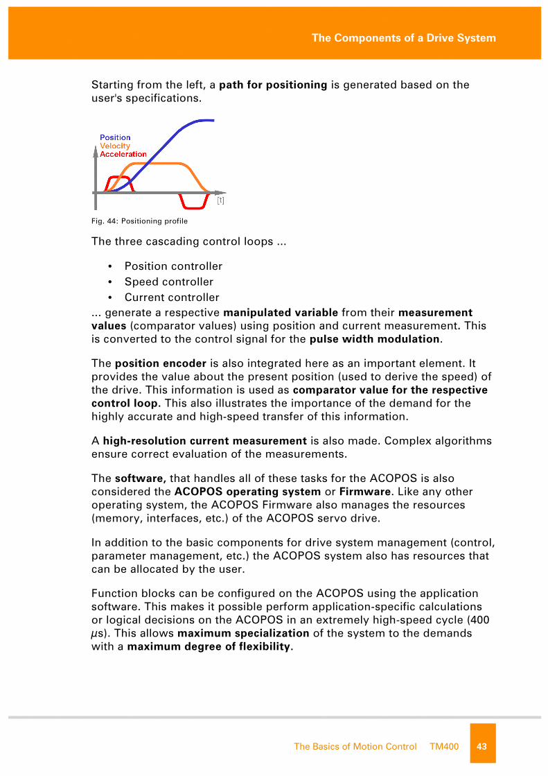
Starting from the left, a path for positioning is generated based on the
user's specifications.
Fig. 44: Positioning profile
The three cascading control loops ...
• Position controller
• Speed controller
• Current controller
... generate a respective manipulated variable from their measurement
values (comparator values) using position and current measurement. This
is converted to the control signal for the pulse width modulation.
The position encoder is also integrated here as an important element. It
provides the value about the present position (used to derive the speed) of
the drive. This information is used as comparator value for the respective
control loop. This also illustrates the importance of the demand for the
highly accurate and high-speed transfer of this information.
A high-resolution current measurement is also made. Complex algorithms
ensure correct evaluation of the measurements.
The software, that handles all of these tasks for the ACOPOS is also
considered the ACOPOS operating system or Firmware. Like any other
operating system, the ACOPOS Firmware also manages the resources
(memory, interfaces, etc.) of the ACOPOS servo drive.
In addition to the basic components for drive system management (control,
parameter management, etc.) the ACOPOS system also has resources that
can be allocated by the user.
Function blocks can be configured on the ACOPOS using the application
software. This makes it possible perform application-specific calculations
or logical decisions on the ACOPOS in an extremely high-speed cycle (400
µs). This allows maximum specialization of the system to the demands
with a maximum degree of flexibility. not f
or re
The Components of a Drive System
44 TM400 The Basics of Motion Control
3.3.4 Differences between frequency converters and servo drives
As we have already discussed several times, there are clear differences
between possibilities offered by a frequency converter and those of a servo
drive in the electrical drive technology.
In the previous section, we got an overview of the servo drive's "intelligent
components" such as the path generator, measurement systems used to
determine the position (encoder system) and application interfaces.
The frequency converter however, does not have these mechanisms!
Why then, did we take the time to go over all of these components? We
could have covered the topic of frequency converters much earlier, right?
The answer is simple – we now know the important characteristics of the
most versatile power converter; the servo drive. From here on out, we are
much better prepared to understand and evaluate the limitations of the
frequency converter as a more basic type of converter.
The conversion of electrical energy from the mains power supply is
performed by the power electronics in the frequency converter based on
the principle described above.
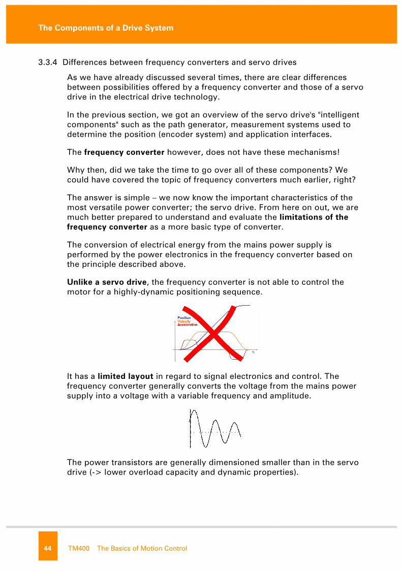
Unlike a servo drive, the frequency converter is not able to control the
motor for a highly-dynamic positioning sequence.
It has a limited layout in regard to signal electronics and control. The
frequency converter generally converts the voltage from the mains power
supply into a voltage with a variable frequency and amplitude.
The power transistors are generally dimensioned smaller than in the servo
drive (-> lower overload capacity and dynamic properties).
not f
or re

The Components of a Drive System
The Basics of Motion Control TM400 45
U/f frequency converter
This is the most basic design of a modern frequency converter. The
converter regulates the motor voltage and frequency in a linear
relationship. This results in a very weak torque at low speeds. The speed
of the connected motor varies depending on its present load. A current
measurement can also be used for compensation (slip compensation)
without requiring feedback about the position from a determination of the
load. This design is sufficient for simple applications with small speed
variation and without heavy starting. Only induction motors can be
operated.
In the classical sense, a frequency converter is basically a speed
positioner:
• Rotating field specification without reference to the rotor position
(not a position encoder)
• Low PWM switching frequencies
• Slow control response – not suited for dynamic processes
• Dimensioning to rated power without overload properties
The differences between frequency converters and servo drives are evident
when making a direct comparison with one another:
Frequency converter Servo drive
PWM ground frequency 4 ... 8 kHz 5 ... 20 kHz
Current controller 0.5 ... 2 kHz 16 ... 20 kHz
Speed controller Optional (2 msec) 0.2 ... 1 ms
Position controller missing 0.4 ... 4 ms
Brake chopper Optional Default
Induction motors Yes Yes
Synchronous motor No Yes
Overload capacity Low High
Highly-dynamic movements No Yes
not f
or re

Integration in the Process
46 TM400 The Basics of Motion Control
4. INTEGRATION IN THE PROCESS
We can recognize the main components of the electronic drive systems
from the previous contents. The core characteristics of the individual
technologies are also familiar.
In the following section, we will get one more overview summarizing the
important points to consider when choosing components.
The challenge for the software developer is to implement the process in
the control program.
4.1 Selecting the technology
The starting point when setting up an electrical drive system is naturally
the process that must be implemented.
All of the necessary machine sequences must be exactly known in order
to estimate the mechanical requirements and the demands placed on the
control system (drive system management, control software):
Power converter
The limitations of the frequency converter compared to the servo drive can
be seen clearly. Processes that require variable speed adjustment, but that
do not require precision positioning or highly dynamic speed profiles can
generally be handled very effectively using a frequency converter.
It is usually used in combination with an induction motor. Common
applications for this type of configuration include:
• Main spindle drive motors (machine tools, textile spinning machines,
packaging machines)
• Conveyor systems with variable speed
• Material transport with variable haul-off speed
• Regulated fan units not f
or re
Integration in the Process
The Basics of Motion Control TM400 47
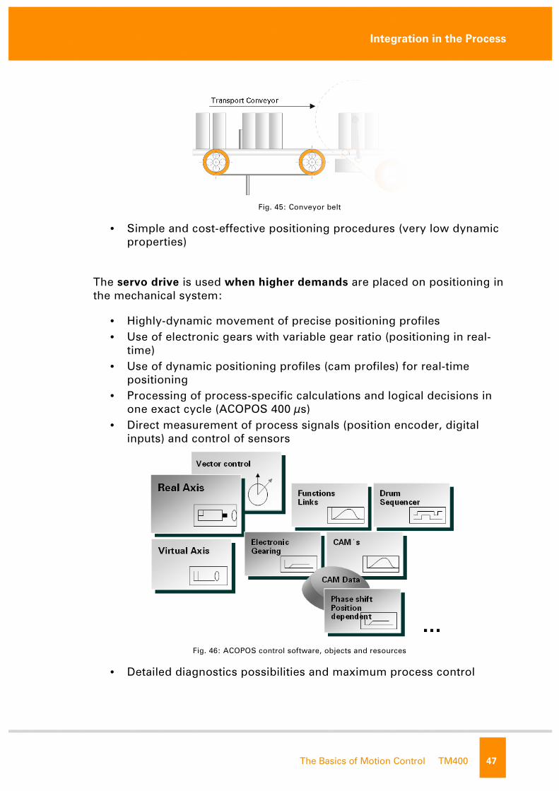
Fig. 45: Conveyor belt
• Simple and cost-effective positioning procedures (very low dynamic
properties)
The servo drive is used when higher demands are placed on positioning in
the mechanical system:
• Highly-dynamic movement of precise positioning profiles
• Use of electronic gears with variable gear ratio (positioning in real-
time)
• Use of dynamic positioning profiles (cam profiles) for real-time
positioning
• Processing of process-specific calculations and logical decisions in
one exact cycle (ACOPOS 400 µs)
• Direct measurement of process signals (position encoder, digital
inputs) and control of sensors
Fig. 46: ACOPOS control software, objects and resources
• Detailed diagnostics possibilities and maximum process control
not f
or re

Integration in the Process
48 TM400 The Basics of Motion Control
Motor
The motor is responsible for converting the electrical energy into a
movement. It must be able to provide the torque for positioning the
mechanical system:
Tmotor = Jmech. ⋅⋅⋅⋅ αααα
Tmotor ... required drive torque
Jmech. ... moment of inertia (mechanical inertia of the entire system)
αααα ... rotational acceleration (dynamic requirement)
The motor must be designed for both average load as well as for the
potential peak loads (instantaneous accelerations, etc.).
As mentioned many times in the previous sections, a permanently excited
synchronous motor working together with a servo drive for control is the
absolute front-runner for dynamic and simultaneously precise positioning.
The B&R product range offers synchronous motor to meet these demands
in a wide range of performance:
• Torque from 0.2 – 115 Nm
• Highly dynamic properties
• High peak torque
• Compact construction, high power density
• Low torque ripple
• Reinforced bearings
• Practically maintenance-free
Fig. 47: B&R synchronous motors
not f
or re

Integration in the Process
The Basics of Motion Control TM400 49
Encoder system
One of the main criteria for the position encoder is the resolution. It is a
decisive factor for how precise positions can ultimately be measured and
controlled.
The quality of drive control is also largely dependent on the encoder
resolution. Additionally, the speed of position evaluation and transfer to
the servo drive also play a decisive role. In this case, optical encoder
systems are superior to the inductive encoder (resolver).
Depending on the application, the constant repetition of the homing
procedure after a system restart is either not possible or not desirable. In
this case, the characteristics of the extended movement range of a multi-
turn encoder can come prove useful.
Fig. 48: Position encoder
Physical limits are also defined for safe functioning of the encoder. Above
all, vibrations and high temperatures can cause problems for the encoder.
In this case, the resolver is more durable with its highly robust
construction. The resolution and control quality offered by the resolver
system is sufficient for many applications.
B&R servo motors with ENDAT encoders and embedded parameter chips
make up a compact plug & play component for drive automation.
not f
or re
Integration in the Process
50 TM400 The Basics of Motion Control
4.2 Developing the control software
As we have seen, modern drive technology encompasses a very wide
range of topics, which can and should include a variety of considerations.
The developer of control software is responsible for implementing the
process at hand in a control program.
Fig. 49: The developer's tasks
It is immensely important to always keep the spectrum of the entire system
in mind so that you can plan in all of the aspects accordingly. Only then
can the approach be optimally "sketched" and implemented.
not f
or re

Integration in the Process
The Basics of Motion Control TM400 51
The drive system is generally controlled by a CPU that is connected with
the servo drive via a communication network (e.g.: ETHERNET-
POWERLINK, CAN etc.).
Fig. 50: CPU – ACOPOS communication
The process flow is implemented in the application program. Software
tools (graphic editors, etc.) and functions for the control process
(positioning commands, etc.) are provided in the development
environment (B&R Automation Studio) for this reason.
Fig. 51: Automation Studio, Motion Components
not f
or re

Integration in the Process
52 TM400 The Basics of Motion Control
The spectrum ranges from simple basic movements...
Fig. 52: basic positioning functions
...to the management of dynamic positioning profiles for complex
applications.
Fig. 53: Cam profile automat
Knowledge of these software-related tools and functions is also important
for us so that we can divide the application into individual function units. A
modular and structured layout of the control software makes it much easier
to create, maintain and expand the software applications.
Note:
The following training modules will deal extensively with the software
tools used for setting up and configuring the B&R drive solution. not f
or re

Summary
The Basics of Motion Control TM400 53
5. SUMMARY
The level of performance of modern drive systems has improved
significantly thanks to technological advancements in the area of power
electronics and signal electronics.
Electrical, IT-related and mechanical components are combined to
automate a process. Optimum coordination of this mechatronic system is
decisive for meeting high demands.
Fig. 54: The fundamentals of the drive system
Even the selection of drive system components must be made in close
coordination with the requirements of the process. The specific
characteristics of the system components and their effects on the entire
system are the main focus in this case.
Basic knowledge about the components, technologies and procedures in
the system is quite useful for the software developer.
With this basis, the mechatronic drive system can be optimally adjusted,
setup and further developed into a function unit that can be used
repeatedly.
not f
or re

Summary
54 TM400 The Basics of Motion Control
Notes
not f
or re

Summary
The Basics of Motion Control TM400 55
Overview of training modules
TM210 – The Basics of Automation Studio TM600 – The Basics of Visualization
TM211 – Automation Studio Online Communication TM610 – The Basics of ASiV
TM213 – Automation Runtime TM630 – Visualization Programming Guide
TM220 – The Service Technician on the Job TM640 – ASiV Alarm System, Trend and Diagnostic
TM223 – Automation Studio Diagnostics TM670 – ASiV Advanced
TM230 – Structured Software Generation
TM240 – Ladder Diagram (LAD) TM700 – Automation Net PVI
TM241 – Function Block Diagram (FBD) TM710 – PVI Communication
TM246 – Structured Text (ST) TM711 – PVI DLL Programming
TM250 – Memory Management and Data Storage TM712 – PVIServices
TM261 – Closed Loop Control with LOOPCONR TM730 – PVI OPC
TM400 – The Basics of Motion Control TM800 – APROL System Concept
TM410 – The Basics of ASiM TM810 – APROL Setup, Configuration and Recovery
TM440 – ASiM Basic Functions TM811 – APROL Runtime System
TM441 – ASiM Multi-Axis Functions TM812 – APROL Operator Management
TM445 – ACOPOS ACP10 Software TM813 – APROL XML Queries and Audit Trail
TM446 – ACOPOS Smart Process Technology TM830 – APROL Project Engineering
TM450 – ACOPOS Control Concept and Adjustment TM840 – APROL Parameter Management and Recipes
TM460 – Starting up Motors TM850 – APROL Controller Configuration and INA
TM480 – Hydraulic Drive Control TM860 – APROL Library Engineering
TM865 – APROL Library Guide Book
TM500 – The Basics of Integrated Safety Technology TM870 – APROL Python Programming
TM510 – ASiST SafeDESIGNER TM890 – The Basics of LINUX
TM540 – ASiST SafeMC
not f
or re

Summary
56 TM400 The Basics of Motion Control
Hinteres Deckblatt (auf durch 4 Teilbarer Seitenzahl)
Kontakt (Headquarter)
Weblink
Internationalität
Copyright – Bestellnummer
TM
40
0T
RE
.00
-EN
G
09
07
©2
00
7 b
y B
&R
. A
ll r
igh
ts r
ese
rve
d.
All r
eg
iste
red
tra
de
ma
rks a
re t
he
pro
pe
rty
of
the
ir r
esp
ecti
ve
ow
ne
rs.
We
re
se
rve
th
e r
igh
t to
make
te
ch
nic
al
ch
an
ge
s
not f
or re


![Servo Motion Controller Basics(Hardware) ENG.ppt [互換モード] · .X-Y table Motion program The application examples of the motion control are introduced in the following. Click](https://static.fdocuments.net/doc/165x107/5d00aa4188c99363028ba1d9/servo-motion-controller-basicshardware-engppt-x-y-table.jpg)

