
The Basics of Drilling for Specialty Geotechnical · PDF fileThe Basics of Drilling for...
21
_______________________ 1 President, Geosystems, L.P., P.O. Box 237, Venetia, PA 15367, Telephone: (724) 942-0570; fax: (724) 942-1911; email: [email protected] 1 The Basics of Drilling for Specialty Geotechnical Construction Processes Donald A. Bruce 1 Abstract The successful execution of a large and important number of specialty geotechnical construction processes necessitates the efficient and safe drilling of holes through any and all ground conditions. Inappropriate means and methods may in fact worsen the ground properties or structural conditions the construction technique is intended to enhance. There is a potentially bewildering variety of drilling methods and associated technical concerns. This review is intended as a fundamental guide to various aspects of the technology, including drilling methodologies, flushing, deviation, monitoring, and specifications. 1. Introduction The specialty geotechnical construction processes of grouting, anchoring, micropiling, soil nailing, and ground freezing all require the drilling of holes through overburden and/or rock. Such holes are typically 75 to 300 mm in diameter and are rarely more than 60 m deep. Holes may range in inclination from vertically upwards to vertically downwards, with most holes for grouting, micropiling, and freezing being within 30º of vertical, and most holes for anchoring and nailing being within 30º of horizontal. Although rock masses are naturally variable in terms of strength and structure, overburden – from the drilling viewpoint – usually poses far greater difficulties to the drilling contractor. For the purposes of this review, overburden is regarded as any non-lithified material, either deposited or formed by nature, or placed or created by man. Such material may range from soft and loose to hard and dense, and from dry to saturated. Overburden may contain alien and/or atypical inclusions or horizons which will be problematical to penetrate – for example boulders or deep foundations in soils, and utility trenches or shallow foundations in fills. Such conditions will challenge the drilling contractor who, for financial reasons, will always want to drill the holes as quickly as possible, with the minimum practical “footage” cost. Equally, however, specific project needs may impose significant restrictions or performance requirements. Thus, drilling anchor holes through and under high concrete
-
Upload
hoangthien -
Category
Documents
-
view
226 -
download
3
Transcript of The Basics of Drilling for Specialty Geotechnical · PDF fileThe Basics of Drilling for...

_______________________ 1President, Geosystems, L.P., P.O. Box 237, Venetia, PA 15367, Telephone: (724) 942-0570; fax: (724) 942-1911; email: [email protected]
1
The Basics of Drilling for Specialty Geotechnical Construction Processes
Donald A. Bruce1
Abstract The successful execution of a large and important number of specialty geotechnical construction processes necessitates the efficient and safe drilling of holes through any and all ground conditions. Inappropriate means and methods may in fact worsen the ground properties or structural conditions the construction technique is intended to enhance. There is a potentially bewildering variety of drilling methods and associated technical concerns. This review is intended as a fundamental guide to various aspects of the technology, including drilling methodologies, flushing, deviation, monitoring, and specifications. 1. Introduction The specialty geotechnical construction processes of grouting, anchoring, micropiling, soil nailing, and ground freezing all require the drilling of holes through overburden and/or rock. Such holes are typically 75 to 300 mm in diameter and are rarely more than 60 m deep. Holes may range in inclination from vertically upwards to vertically downwards, with most holes for grouting, micropiling, and freezing being within 30º of vertical, and most holes for anchoring and nailing being within 30º of horizontal. Although rock masses are naturally variable in terms of strength and structure, overburden – from the drilling viewpoint – usually poses far greater difficulties to the drilling contractor. For the purposes of this review, overburden is regarded as any non-lithified material, either deposited or formed by nature, or placed or created by man. Such material may range from soft and loose to hard and dense, and from dry to saturated. Overburden may contain alien and/or atypical inclusions or horizons which will be problematical to penetrate – for example boulders or deep foundations in soils, and utility trenches or shallow foundations in fills.
Such conditions will challenge the drilling contractor who, for financial reasons, will always want to drill the holes as quickly as possible, with the minimum practical “footage” cost. Equally, however, specific project needs may impose significant restrictions or performance requirements. Thus, drilling anchor holes through and under high concrete
2
dams often demands holes of unusually tight deviation tolerance (Bruce, 1989), drilling for micropiles must not lead to further settlement of the structure being underpinned (FHWA, 1997), and drilling for soil nails must not cause slope instability (FHWA, 1993).
Another particularly illustrative example in this regard is the U.S. Army Corps of Engineers Regulation (1997) pertaining to drilling in earth embankments. As historical background, this document notes that “in the past” compressed air and various drilling fluids have been used as circulating media while drilling through earth embankments and their foundations. Despite widespread success, there have been examples resulting from pneumatic or hydraulic fracturing, and/or erosion. The Regulation therefore mandates the following: 1. Strong qualifications are required from all personnel involved in the design or
construction of such drilling works. 2. “Drilling in embankments or their foundations using compressed air (including air
with foam) or any other gas or water as the circulating medium is prohibited” (underline added).
The Regulation does permit auger drilling (no flush), cable tool (churn), or rotary drilling with “an engineered drilling fluid (or mud).” A separate appendix details acceptable practices for rotary drilling.
The very strong, non-negotiable nature of this Regulation is typical of many similar position statements made by various agencies over the years: Deere (1982) noted that “many of the former specifications in the United States required the holes to be drilled by rotary means.” However, in the same year, Albritton, himself from the Corps, reported that “actual drilling methods are normally left up to the contractor, subject to specified restrictions and Corps approval.” More recently, PTI (1996) recommended that “drilling methods shall be left to the discretion of the contractor, wherever possible,” provided that “special concerns” were satisfied. Such concerns include noise, vibrations, alignment, damage to existing structures, and hole stability.
In support of this “performance” based mentality, this paper presents a summary of contemporary information relating to rock and overburden drilling. It is written from the practitioner’s viewpoint, and presumes of its reader a basic awareness of typical drilling terminology, applications, and problems. 2. Systems, Methods and Applicability 2.1 Commonalities Effective drilling systems must be capable of permitting continuous and straight penetration in materials which may vary from very soft to extremely hard. They must be capable of providing a constant diameter, stable, (or temporarily stabilized) path full depth, from which the drilling debris have been wholly removed, and which is consistent with the needs of the specialty construction process it enables. They will employ appropriate combinations of thrust, torque, rotary speed, percussive effort, and flush parameters to economically reach target depth. They must facilitate the effectiveness of the flushing medium used. They must ideally be dictated by the ground conditions, cost notwithstanding, although historical bias
3
and regional experience are often a common determinant. Application should determine technique. The method must also satisfy project environmental restraints including noise, vibrations, and flush control and disposal. The hole must be used for its intended purpose (e.g., anchor tendon installation) as soon as possible after drilling to minimize any time dependent deterioration of its walls. 2.2 Rock Drilling There are three methods of rock drilling for production holes:
• Rotary - High rotational speed, low torque and thrust - Low rotational speed, high torque and thrust • Rotary Percussive - Top hammer
- Down-the-hole hammer • Rotary Vibratory (Sonic)
2.2.1 Rotary High rotational speed (i.e., ≥ 600 rpm), low torque, low thrust: relatively light drill rigs can be used to extract core samples, when using a core barrel system, or can also be used simply to drill “footage,” using “blind” or “plug,” surface set or impregnated, diamond, or tungsten insert bits. Kutzner (1996) reports that instantaneous penetration rates are higher for core drilling, than for full face (“blind”) drilling, but that the latter is more economical the deeper the hole (by 50 to 100%) since no time is lost retrieving core runs. The method is typically used for holes up to 75 mm diameter to depths of 50 to 150 m.
Advantages of high speed rotary drilling include: • The same equipment can be used for both investigatory and production hole drilling. • Continuous or intermittent exploration of the rock is possible over the entire length of the
hole. • Drilling can be done to relatively great depths (300 m). • Relatively straight holes can be drilled with less deviation than top hammer rotary
percussion. • No or limited clogging of the rock fissures typically occurs. • It is possible to drill in all kinds of rock. • It is possible to use most power alternatives to drive the equipment (i.e., air, electricity,
diesel). • Rotary drill bits produce smooth hole walls which make subsequent packer installation
easier for rock grouting. • Good penetration speeds can be achieved in soft formations (1 to 10 m/hour: Kutzner,
1996). • No vibrations are imparted to the rock formation and adjacent structures.
Despite these advantages which are widely exploited in certain applications (e.g., deep mineral mines), the use of this drilling method is declining in geotechnical construction, largely on economic grounds under competition from rotary percussive methods in particular.
4
Rarely are coring methods used for production drilling, except in situations where heavily reinforced concrete must be first penetrated. Low rotational speed, high torque, high thrust: used with heavier and more powerful rigs to drill holes of greater diameter to considerable depths. The penetration rate depends largely on the amount of thrust applied to the bit. A variety of carbide tipped tricone roller, or finger bits are used, to penetrate via “grinding and shattering” mechanisms (Houlsby, 1991). PTI (1996) notes that “rotary drills equipped with continuous flight augers…are commonly used to advance uncased holes in soft rocks or soils.” This technique is discussed in Section 2.3, below. 2.2.2 Rotary Percussive The drill bit (carbide insert, cross or button) is both percussed and rotated. In general the percussive energy determines the penetration rate. With a top hammer, the drill rods are rotated and percussed by the drill head on the rig. With a direct circulation down-the-hole hammer, the (larger diameter) drill rods are only rotated by the drill head, and compressed air fed down the rods activates the percussive hammer mounted directly above the drill bit. Top hammer drilling is performed at rotation speeds of approximately 80 to 160 rpm to provide hole diameters seldom above 102 mm. Hole depth is limited to approximately 60 m by power availability, and by hole deviation concerns. Due to the path by which the energy is transferred to the bit (i.e., via successive rod couplings), penetration rate decreases with depth. Down-the-hole drilling is performed at approximately 10 to 60 rpm in hole diameters above 90 mm to depths of over 100 m. Since the percussive effect is applied immediately above the bit, regardless of depth of hole, penetration rate is constant with depth, other factors being equal. Advantages of percussion drilled grout holes include: • higher (by a factor of 5 or more – Deere, 1982) and consistent penetration rates than
rotary methods (10 to 20 m/hour according to Kutzner (1996)); • relatively small, light, and mobile drill rigs can be used; • low drilling costs; • down the hole drilling provides the potential for minimal hole deviation with production
rates of 5 to 15 m/hour (Kutzner, 1996). There are currently four basic concepts in down the hole (DTH) drilling • Direct circulation (DC) air-driven DTH hammers, with the returning air flush in contact
with the sidewalls of the entire length of the drill hole. • Reverse circulation (RC) DTH hammers utilize dual wall drill rods and can also use air,
or air with a water mist. The flush is returned to the surface through the inner orifice and so it helps to increase hole cleanliness by protecting the hole from the drill cuttings and flushing medium. Care must be taken to ensure that plugging of the inner drill rod is always avoided.
• Dual Fluid Drilling Systems (DFS) is a new concept comprising a special air-activated DTH, hammer, which incorporates a center tube through the hammer body that allows

5
water to be used as the sole flushing medium. The driving air is exhausted between the outer casing and the inner drill string and so never contacts the rock. This system has the lowest DTH penetration rate potential.
• Water DTH Hammers (WH) use water at high pressures (about 20 MPa) to activate the hammer and flush the hole. A potential technical draw back is that the formation will be exposed to these very high pressures, resulting in the possibility of localized ydrofracture.
In principle, the prime technical controls over the choice of drilling method should ideally be the geology, and the hole depth and diameter. Other considerations such as hole linearity and drill access restraints may also have significant impact on choice on any given project. 2.2.3 Rotary Vibratory (Sonic) This technique was developed in the late 1940s and is becoming increasingly popular where strong environmental restraints are in force. It is a dual cased system that uses high frequency mechanical vibration to provide continuous core samples, or simply to advance casings for other purposes, such as deep wells or freeze holes. The string is vibrated at continuously adjustable frequencies between 50 and 150 Hz, and is rotated slowly in harder formations to evenly distribute energy and bit wear. The frequency is adjusted to achieve maximum penetration rate by coinciding with the natural resonate frequency of the drill string (Figure 1). Resonance provides extremely high energy to the bit, and in soil it also displaces laterally the particles, greatly facilitating penetration rate. Penetration is optimized by varying frequency and thrust parameters.
Figure 1. Principles of sonic drilling. (Alliance Environmental Inc., 1999)
6
Regarding its advantages, sonic drilling • can provide continuous cores in soil (75- to 250-mm-diameter) without using flushing
media, at very high penetration rates; • can readily penetrate obstructions (natural and artificial); • has been used to depths of 150 m; • can easily convert to other types of rock or overburden drilling; and • requires no flush in overburden, and only minor amounts in rock.
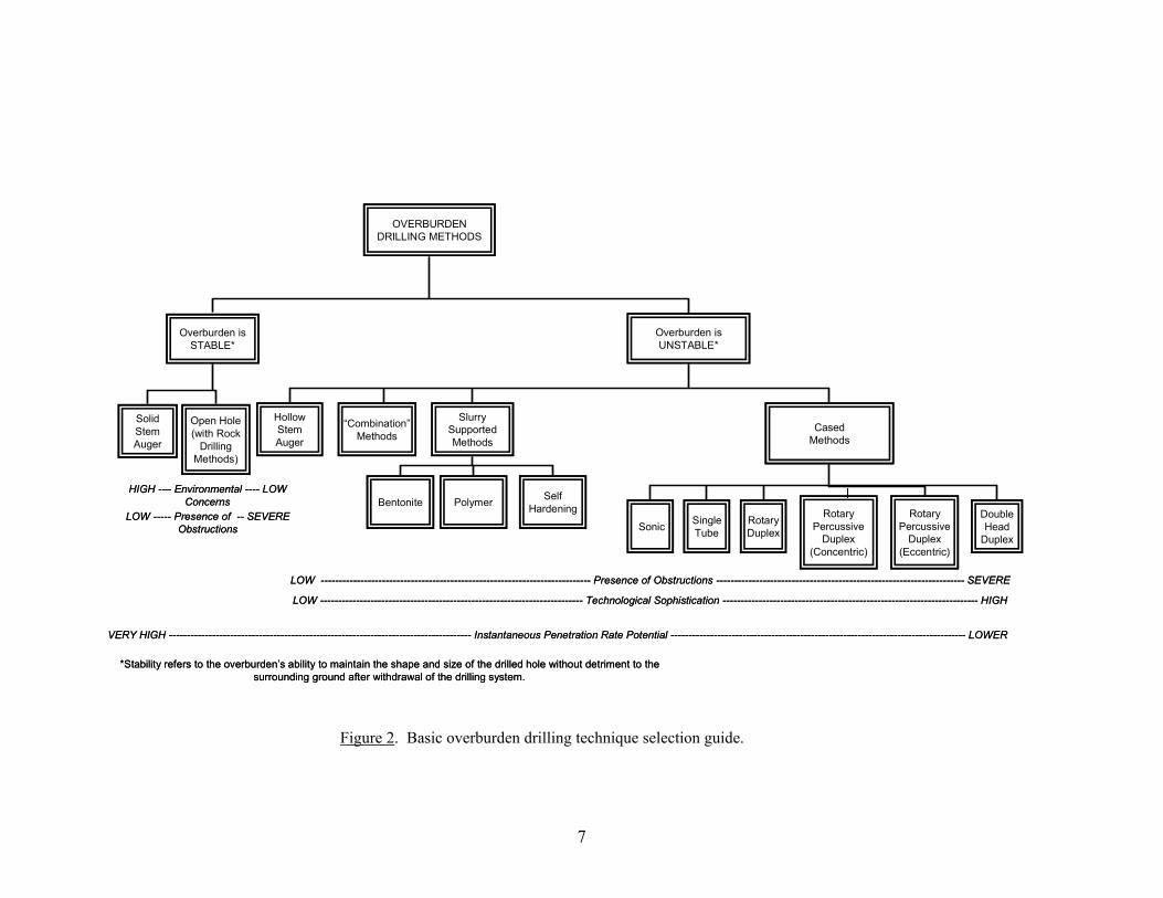
Several major geotechnical construction-related applications have been recorded to date including projects through dam embankments. The rotosonic system has exceptional potential for rock and soil drilling in certain combinations of circumstances. In the clever promotional words of its developers, it may be indeed be “the wave of the future” in drilling technology in many applications. 2.3 Overburden Drilling As noted in Section 1, overburden drilling can be more complex and difficult than rock drilling, and is often far more controversial when consideration is given to levels of environmental acceptability. Regarding the fundamental control exerted by the stability of the drilled hole (i.e., its ability to maintain shape and size without detriment to the surrounding ground after withdrawal of the drilling system), Figure 2 provides the basic method selection guide. It must be noted that this relates only to routine production drilling for geotechnical construction purposes: core drilling in overburden is not viable in this context although it is obviously an integral part of many exploration and verification projects.
Equally important in the selection of the appropriate drilling method may be one, or a combination of the following: • Cost considerations (per lineal meter, and as related to project size). • Drill rig access restraints. • Hole depth, diameter, and inclination. • Flush collection and disposal concerns; noise; vibrations. • Possible impact of method on subsequent ability of hole to satisfy the project goals (e.g.,
bentonite slurry must not be used to stabilize holes which must later transfer peripheral bond, as in the case of nails, anchors, and micropiles)
• Regional preference, and contractor paradigms, experience, and resources. It must also be recalled that certain construction techniques have overall geotechnical
limitations. For example, soil nailing is only feasible in soils with “standup time”: 80 to 90% of drilling for soil nails can therefore be conducted with open hole methods (FHWA, 1993).
Given that thorough reviews may be found in several sources (Bruce, 1984; Houlsby, 1990; Weaver, 1991; Xanthakos et al., 1994; Kutzner, 1996; Australia, 1997), the following discussion provides only brief notes on the various techniques cited in Figure 2. 2.3.1 Stable Soil Methods
2.3.1.1 Solid Stem Continuous Flight Augers (SSCFA). In appropriate soils, and when in a single continuous string, mounted on large crawler mounted rigs or suspended from
7
Figure 2. Basic overburden drilling technique selection guide.
OVERBURDENDRILLING METHODS
Overburden isSTABLE*
Overburden isUNSTABLE*
SolidStemAuger
Open Hole(with Rock
DrillingMethods)
HollowStemAuger
“Combination”Methods
SlurrySupportedMethods
CasedMethods
VERY HIGH ------------------------------------------------------------------------------------ Instantaneous Penetration Rate Potential ---------------------------------------------------------------------------------- LOWER
LOW ------------------------------------------------------------------------- Technological Sophistication ----------------------------------------------------------------------- HIGH
LOW --------------------------------------------------------------------------- Presence of Obstructions --------------------------------------------------------------------- SEVERE
LOW ----- Presence of -- SEVEREObstructions
HIGH --– Environmental ---- LOWConcerns
Sonic SingleTube
RotaryDuplex
RotaryPercussive
Duplex(Eccentric)
DoubleHead
Duplex
*Stability refers to the overburden’s ability to maintain the shape and size of the drilled hole without detriment to thesurrounding ground after withdrawal of the drilling system.
Bentonite Polymer SelfHardening Rotary
PercussiveDuplex
(Concentric)

8
crane leads, SSCFA can provide extremely high productivities. SSCFA is a traditional, relatively simple technology, often used for soil nailing in the Western United States and parts of Europe, providing holes 100 to 300 mm in diameter to maximum lengths of about 28 m (FHWA, 1993). 2.3.1.2 Rock Drilling Methods. Where flush return need not be carefully controlled, on technical and/or environmental grounds, then rotary or rotary percussive methods can be used, as described in Section 2.2 above. Such methods may be used to “predrill” through bouldery or otherwise obstructed overburden as a prelude to the subsequent installation of a casing (Bruce and Yeung, 1983). Use of such methods in overburden must only be conducted with extreme care especially when slope or structural stability is an issue. Examples of successful use include nail hole drilling, and predrilling for micropiles and jet grouting in karstic limestone (e.g., Bruce et al., 2001). 2.3.2 Unstable Soil Methods
2.3.2.1 Hollow Stem Continuous Flight Augers (HSCFA). These are used in unobstructed ground to maximum depths of 30 m for a wide range of applications (150 to 400 mm in diameter). PTI (1996) notes that for anchors, auger outside diameters of 200 to 450 mm and inside diameters of 65 to 105 mm are typically used, protected by “knock off” bits. This technique is not recommended for holes shallower than 30º (for deviation control) or in cohesionless or uncemented soils, particularly under the water table (for cavitation prevention). HSCFA does not permit the application of high grout pressures during withdrawal of the auger, following placement of the central tendon or grout tube. 2.3.2.2 Combination Methods. Combination methods involve two or more principles combined to meet or exploit certain ground or project restrictions. For example, an open ended casing can be driven or rotated full depth without flush. The soil which is left inside the casing is then augered or flushed out without fear of flush escaping into the surrounding ground mass. This method was described by Fox and Jones (1982) for drilling through the clay of a dam core: the use of pressurized flush during the casing advancement was not acceptable due to concerns regarding pneumatic fracture of the core. 2.3.2.3. Slurry Supported Methods. In unobstructed ground, a common choice for quickly penetrating through potentially unstable materials (e.g., cohesionless soils) is to use some form of drilling slurry in combination with rotary drilling. As opposed to the use of water or air (Section 4), such slurries have a range of specific gravities, and viscosities and will have other properties, such as the ability to coat the borehole wall with a coat or “filter cake” of material, creating stability. Slurries can be prepared from bentonite, polymer, or (as in Italy) a “self hardening drilling mud,” i.e., a clay slurry incorporating cement. It is essential that the method is not in conflict with project goals: bentonite slurry should not be used for anchors, nails, or micropiles, while polymer slurries must totally degrade when touched by cement grout tremied into the hole (“calcium shock”). The special logistical provisions needed to mix, inject, collect, clean, and recycle such slurries may offset the potential advantages of high productivity afforded by this method. 2.3.2.4. Cased Methods. Based on installing casing by rotary or rotary percussive methods, the classification is shown in Table 1. In general, the methods are arranged in ascending order of technological complexity, the particular need for which will reflect the “difficulty” of the ground, and environmental restrictions. Thus, in most urban areas, and particularly in ground containing natural and artificial obstructions, some form of cased method is essential. Contractors east of the Mississippi River, and in the Pacific Northwest therefore tend to have the most experience and expertise. All methods except Method 1a (Drive Drilling) need some type of drill flush. An excellent level of technical support and advice is also available from the manufacturers and suppliers of drilling rigs and
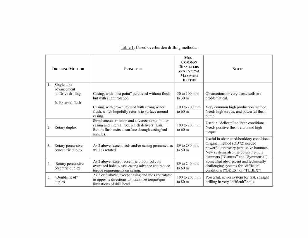
Table 1. Cased overburden drilling methods.
DRILLING METHOD PRINCIPLE
MOST COMMON
DIAMETERS AND TYPICAL
MAXIMUM DEPTHS
NOTES
1. Single tube advancement a. Drive drilling
b. External flush
Casing, with “lost point” percussed without flush but with slight rotation Casing, with crown, rotated with strong water flush, which hopefully returns to surface around casing.
50 to 100 mm to 30 m 100 to 200 mm to 60 m
Obstructions or very dense soils are problematical. Very common high production method. Needs high torque, and powerful flush pump.
2. Rotary duplex
Simultaneous rotation and advancement of outer casing and internal rod, which delivers flush. Return flush exits at surface through casing/rod annulus.
100 to 200 mm to 60 m
Used in “delicate” soil/site conditions. Needs positive flush return and high torque.
3. Rotary percussive concentric duplex
As 2 above, except rods and/or casing percussed as well as rotated.
89 to 280 mm to 50 m
Useful in obstructed/bouldery conditions. Original method (OD72) needed powerful top rotary percussive hammer. New systems also use down-the-hole hammers (“Centrex” and “Symmetrix”).
4. Rotary percussive eccentric duplex
As 2 above, except eccentric bit on rod cuts oversized hole to ease casing advance and reduce torque requirements on casing.
89 to 240 mm to 60 m
Somewhat obsolescent and technically challenging systems for “difficult” conditions (“ODEX” or “TUBEX”)
5. “Double head” duplex
As 2 or 3 above, except casing and rods are rotated in opposite directions to maximize torque/rpm limitations of drill head.
100 to 200 mm to 80 m
Powerful, newer system for fast, straight drilling in very “difficult” soils.
10
equipment. Most are headquartered in Italy, Germany, France, Finland, and Sweden, but operate through agents in North America. New developments are regularly described in the technical press, in particular Geodrilling International and ASDC’s Foundation Drilling. As noted in Section 2.2.3 (above), sonic drilling also has great potential for the installation of casings through overburden, and into rock. 3. Drilling Equipment The references cited in Section 2.3 above provide a wealth of data on drilling rig and drill head operational capabilities for a wide range of equipment provided by international manufacturers. Fundamentally, there are several key factors which should logically lead to the selection of the best rig for any project: • Power: must allow the chosen drilling method to be used with maximum efficiency. • Thrust/Pull back: must give appropriate thrust during drilling, and sufficient pull back
from the maximum drilling depth. • Maneuverability: must permit the drill hole to be drilled at every angle and azimuth with
minimal delay between set ups. • Stability: must ensure that the mast remains constant in orientation during drilling with
minimal vibration or “drift”. • Accessibility: must permit access to all hole locations, even if in low headroom, tight
access locations or steep slopes. • Noise emission: must satisfy regulatory requirements. • User friendliness: must be readily and safely operable by personnel who may not be fully
acquainted with the particular rig type. There is a wide range of equipment sizes, ranging from very light frame-mounted/ hand-held gallery rigs through the “work horse” 100- to 150-Hp diesel hydraulic track rigs, to large, almost wholly automatic rigs with all the rods and casings pre-mounted in magazines or carousels. Even very powerful rigs can operate in very low headroom conditions (less than 2.5 m) and by virtue of modular construction or “expandable” track bases, can reach drill locations through man entry openings (1 m wide). Rigs often can use a variety of rock and overburden drilling systems and all flush types. Drill rod/casing lengths as little as 1 m or as much as 20 m can be accommodated depending on project constraints. Rigs can operate off air, diesel, or electric power sources, in open air locations, cliff sides, underground galleries or tunnels, and active shopping malls (Cadden et al., 2001). Specially designed features such as swiveling drill heads and hydraulic rod and casing breakers reduce human effort, increase safety, and promote higher outputs. The ability of contractors to use cranes, rough terrain vehicles, trucks, and excavators, as well as conventional crawler-mounted bases, to mount drill systems upon, is a common benefit to all parties, and the project itself. 4. The Significance of Circulation Type and Application Efficient flushing is needed to cool the bit and to remove cuttings from the hole to avoid regrinding and consequent drop in penetration rates and increased bit wear. The wrong choice of flush (e.g., compressed air in fine grained, loose, saturated soil) may cause severe cavitation and loosening of the soil, as well as uncontrolled loss of what is a high pressure,
11
highly mobile fluid into the ground and contiguous structures. It may also clog fissures and reduce the formation’s amenability to subsequent grout injection. Simply, the uphole velocity (UHV) of the flushing fluid must exceed the “sinking velocity” (Kutzner, 1996) of the cuttings produced during drilling. UHV is calculated as follows: UHV (m/min) = 1274 x Flush Pump Rate (Liters/min) D2 – d2 (mm) where D and d are respectively the diameters (in millimeters) of the hole and the drill string. According to Australia (1997), acceptable UHVs are as follows:
Air, or air/water “mist”: 1500 m/s (maximum 2100 m/s Water: 36 m/s (maximum 120 m/s)
Low to medium viscosity mud: 30 m/s Very thick mud: 18 m/s
Foam: 12 m/s Although a high UHV is desirable, excessive UHV may cause erosion of the borehole wall. In general, detrital particle sizes are rarely greater than 3 mm depending on ground and drill methodology. The issue of selecting the most appropriate circulating medium is very close to the adversarial hearts of many specialists, especially those involved in rock fissure grouting, as illustrated in the following review of significant opinions: • Deere (1982): any rock drilling method may be selected which prevents “slimes”
occurring, or bits blocking. • Albritton (1982): USACOE traditionally required water flush. However, in some
instances water was found to cause hole caving, erosion, or bit blockage, in which case air “is required for best results.” Percussion drilling with air can cause premature plugging of fine fractures or joints. “Blind drilling” (i.e., without flush, or after losing flush) is to be avoided for grout holes, while care must be taken not to “overpressurize the formation,” via blockages in the escape path annulus.
• Houlsby (1990): the fundamental issue (for rock drilling for fissure grouting) is to select a method based on a) “the suitability of cuttings: Do they clog the cracks and prevent entry of grout?” and b) economics (i.e., rotary vs. rotary percussion penetration rates). The decision is based on observations of the cuttings (which must not be “slimey, puggy, or adhesive”), borehole TV information, and drilling rates and costs. He insists on water flush for grout holes, but other media are suitable for other applications provided no blockages or plugs develop which will cause fracturing in the ground.
• Weaver (1991): “diamond drilling with rotary equipment has long been favored for drilling grout holes (in rock), as it has been thought to produce a cleaner, more groutable hole than does percussion equipment. However, as this has proven not to be the case if water circulation is used for percussion drilling, the greater speed and economy of the latter method has led to its increasing use.” However, rotary drilling may still be preferable in relatively soft materials (claystones weathered sandstones and weak shales)

12
where the flushing ports of percussion bits may tend to become plugged. For percussion drilling (down-the-hole), air flush alone is permitted only in “saturated rock” where the groundwater inflow is substantial enough to keep the fissures clean. This is, however, poor practice in rock with weathered, clayey or silty materials which may clog fissures and create foundation damage through overpressurization. For top hammer drilling, expulsion of cuttings is more difficult (larger chips, larger annulus), and ultimately a foaming agent is added to the air and water flush. The use of special water flushed and activated down-the-hole hammers has not been widespread since their development over 30 years ago, although most recently use has increased.
• Xanthakos et al. (1994): water flush is most adept at cleaning debris from fissures, whereas air has the opposite effect. The use of down-the-hole hammers for rock fissure grouting even when accompanied by “water mist” is of doubtful validity. However, for drilling to penetrate “large voids or other extremely permeable horizons” air is permissible.
• PTI (1996): “the use of drilling muds and foams has greatly expanded the application [of rotary drilling]…to different types of soils. The use of mud or foam must be carefully evaluated to prevent any remaining fluid from significantly affecting grout to ground bond.”
• Kutzner (1996): “Percussion drilling leads to coarse chips and to increased damage to the borehole in comparison to rotary drilling. Therefore careful washing of the boreholes with compressed air and water should be applied before grouting works are commenced.”
• FHWA (1999): “the size of the drill cuttings can vary from a muddy clay to flaky gravel. Different drilling methods produce cuttings that vary in form, size, and shape. All holes drilled for grouting must be cleaned carefully of drill cuttings and loose ground material lodged in the cracks. In general, this is done by high pressure water flushing from the bottom up towards the collar of the hole.”
In summary, the following rules can be restated for selecting appropriate flush type and injection/retrieval characteristics: • Must provide a clean hole. (This can be assessed by inspection of test holes by
appropriate instrumentation e.g., optical Televiewer) • Must enhance drill penetration rates and minimize tool wear. • Must be consistent with the geotechnical construction purpose of the hole. • Must not damage the surrounding formation and/or structures. • Must be environmentally compatible. • When flush is lost fully or substantially during drilling, stop drilling and regroup. As a final point, the term “reverse circulation” (RC) is often incorrectly used in geotechnical drilling. RC (as introduced in Section 2.2.2) refers to the situation when flush is introduced outside of the drill rod, and returns to the surface up the inside of the drill rod. This promotes high UHV and is a useful technique in larger diameter, deeper holes in variable and difficult geology.
13
5. Borehole Deviation 5.1 Significance Every hole has the potential to deviate from its intended path in the ground, even when the drilling rig mast has been and remains precisely oriented. In this regard, set up tolerances of over 3º should not be permitted, while “collar” position should not be more than 75 mm from that designed. The amount of drill hole deviation depends on a variety of often coincident factors including • Nature of subsurface (stratigraphy, structure, obstructions). • Nature of surface conditions (i.e., quality of “drill platform” stability) • Nature of drilling method and tooling (technique; diameter; rods – type, couplings, and
lengths). • Accuracy of initial drill setup. • Inclination and length of hole. • Expertise and technique of the driller. • Nature and length of any guide casing or tube (eg., preplacing of standpipe through
overburden to allow rock drilling below) • Use of special stabilizing devices. As detailed in Section 5.2 below, the amount of deviation recorded on projects or otherwise “proposed” widely varies. Bearing in mind that drilling costs may increase substantially as progressively tighter tolerances are targeted, then the practitioner must be pragmatic when considering how accurate the hole trajectory has to really be before the project goals are compromised. For example, a 4% deviation for short soil nail, or rock mass drainage holes may be acceptable, but will be wholly unacceptable for long holes for anchors through a high, thin arch dam (Bruce et al., 1991). Conversely, a 2% deviation may lead to untreated “windows” in a deep grout curtain, or intersection of long tiebacks installed on a “salient” corner of a deep excavation. A 1% deviation may prove as difficult to measure accurately as to drill. 5.2 Recorded Deviations Table 2 provides information from recently published papers. 5.3 Measurement of Deviation Drill hole deviation is in fact rarely measured in routine construction practice. However, special project requirements, e.g., deep jet grouted cut offs, long dam anchors, or long horizontal holes for compensation grouting may dictate that some (e.g., 2 to 3%) or occasionally all of the holes will have to be surveyed as a basic quality control check. It is simply not technologically feasible to measure and display, continuously and in real time, deviation data for drilling, unlike the case in Deep Mixing or hydromill diaphragm walling (Bruce et al., 1989). At best, the drilling can be interrupted in short (6 m) discrete intervals, and the hole trajectory sensed, e.g., by use of a rate gyro inclinometer, as used at Stewart Mountain Dam, Arizona (Bianchi and Bruce, 1993). In the vast majority of cases, however,

14
Table 2. Summary of recorded drill hole deviations from more recently published data.
SOURCE APPLICATION METHOD RECORDED DEVIATION
Bruce (1989) Dam anchors in rock and concrete
Down-the-hole hammer and rotary
Target 1 in 60 to 1 in 240 Mainly 1 in 100 or better achieved
Bruce and Croxall (1989)
Deep grout holes in fill
Double head Duplex
Achieved 1 in 50 to 1 in 1000 (average 1 in 80)
BS 8081 (1989) Ground anchors General 1 in 30 “should be anticipated”
Houlsby (1990)
Grout holes in rock Percussion Up to 1 in 10 at 60 m
Down-the-hole hammer 1 in 100 increasing to 1 in 20 with increasing depth (70 m) Weaver
(1991) Grout holes in rock “Dry Drilled
Percussion” 1 in 6
Bruce et al. (1993)
Dam anchors in rock and concrete
Down-the-hole hammer Target 1 in 125: consistently achieved as little as 1 in 400
Xanthakos et al. (1994) General in soil Drive Drilling Up to 1 in 14
Percussion Up to 1 in 20 Down-the-hole Up to 1 in 50 Rotary Blind Up to 1 in 33 Rotary Core Up to 1 in 100
Grout holes in rock
Wireline Core Up to 1 in 200 “Una
void
able
”
Kutzner (1996)
Horizontal holes in soil Percussive Duplex Less than 1 in 100
PTI (1996) Tiebacks General statement Up to 1 in 30 normally acceptable High Speed Rotary 2 to 5 in 100
Top Drive Percussion < 5 to 20 in 100 depending on depth
FHWA (1999) General
Down-the-hole hammer Typically 1 to 2 in 100 the hole trajectory is measured upon total, or semi-completion of the hole, and is therefore a retrospective piece of information. In the simplest form, trajectory can be measured in a dry, vertical hole by lowering into it a lit flashlight (face upwards) and observing visually any eclipse in the illuminated face with depth. Alternatively, just using a flashlight to look down or along a hole will provide a visual indication of deviation and straightness. In dry holes, inclined as much as 45º off vertical, a wheel mounted trolley/target can be inserted: lateral movement of its center, relative to the center of the drill collar, can be measured by optical observation of an illuminated target on its surface. More sophisticated techniques include photographic and electronic inclinometers, “for tridimensional borehole survey” (Kutzner, 1996). Photographic instruments involve a compass, movable pendulum, camera, and light source placed inside a watertight tube,

15
lowered into the hole to one, or a series of discrete locations. Pictures of the pendulum position relative to the compass are taken at defined time intervals, with the tube temporarily held motionless. Although the film can be processed and evaluated on site immediately after completion of the survey, the data are retrospective. Electronic instruments comprise a torpedo-shaped probe with inclinometers (x and y coordinates). To prevent rotation, the probe must engage grooves in inclinometer pipes, placed temporarily in the drill string or the hole. Data are relayed to the surface for reduction and display (Kutzner, 1996). The current “state of the art” would appear to be represented by the Optical Televiewer Probe (OPTV) provided by Robertson Geologging Inc. This couples a borehole digital camera with a 3-D deviation survey magnetic instrument. With proper software and interpretive skills, the following data can be generated:
• Fracture states: cumulative thickness, cumulative number, density, frequency histograms.
• Dip plot: arrow plot, stick plot, rose diagrams • Borehole verticality: deviation and drift projection onto horizontal/vertical planes, 3-
D orthogonal projection. • Stereograms: selectable attributes and depth ranges including mean-dip and zone-axis
calculations Where it is not possible to use a magnetically based instrument of this type, optical instruments of the MAXIBOR type have proved popular and very accurate. These can be used inside drill casings. Clearly there are significant technical and logistical advantages in using the rate gyro inclinometer type instrument, although its sophistication, and proprietary aspects, render it a relatively expensive option. It will also be found that, on a project-specific basis, the project requirements can be met by ingenious adaptation of quite basic existing technology (e.g., Heenan et al., 2003). 6. Recording of Drilling Progress and Parameters The three basic steps of a grouting related program are, sequentially, site exploration/evaluation, project execution, and product verification. Steps 1 and 3 typically provide data on the ground properties via special types of testing (e.g., coring, density evaluation, permeability measurement) which are not used or necessitated during the intermediate step of construction. However, it is often overlooked that an equally important volume of data can be obtained from sensible and pragmatic monitoring of the drilling conducted during construction, especially since far more production drilling will usually be conducted than exploratory or verification data. Such information is best used in real time to illustrate the satisfactory progress of the work, or indicate need for appropriate modifications. All drillers keep (or are told to keep!) manual logs in triplicate, in real time, of the conditions encountered during the drilling of each hole. However certain logs contain minimal detail and are therefore of commensurate value: cryptic notes written with a large diameter, soft pencil on note pads purloined from the motel du jour usually end up lost in the wash, literally. Happily, the efforts of contractors, owner agencies, and trade associations which organize “drill schools” are generally improving standards of logging, whether

16
conducted by the drillers themselves, or by supervisory personnel. Logs must describe fully the operation (location, means, methods, and other physical identifiers), and the ground conditions encountered, as evidenced by penetration rate, flush and detritus return, and so on (Weaver, 1991). However, the most informative observations often relate to the “exceptions and unexpecteds,” such as marked variations in penetration rate, flush characteristics, drill response (“chattering”) or hole stability. Such observations may well have contractual, as well as technical significance, both in real time and retrospectively. Many U.S. practitioners were somewhat surprised to learn from Caron (1982) that the (then) new generation of “powerful drilling machines” were “generally fitted with a borehole parameter recorder”: such sophistication was in fact virtually unknown and unused in North America (and – it may be postulated – Europe outside of France and Italy) at the time. In fact, it would seem that the first application was in France in the early 1970s (Hamelin et al., 1982). However, what is now known generically as MWD (Measurement While Drilling) is an integral part of drilling technology in certain applications where the subsequent activity in the hole is best driven by the detailed nature of the ground itself (e.g., jet grouting). MWD is a method for the continuous monitoring, measuring, recording, display, and processing of the instantaneous drilling parameters, such as penetration rate, hold back, thrust, torque, rotational speed, percussion variables, flush flow rate and pressure, with both time and depth of hole. Such data can be correlated with data from adjacent cored holes to give the method a “stratum recognition” ability, as has been routinely done in the petroleum drilling industry for several decades. Adaptation to geotechnical construction processes has proceeded in phases, not unrelated to developments in computer software, and has been largely driven by specialty geotechnical contractors. For example, DePaoli et al. (1987) described how theoretical and experimental work has been conducted, exploiting the concept of specific energy, e: E = F + 2 π N T A AR where e = specific energy (kJ/m3) F = thrust (kN) A = cross sectional area of hole (m2) N = rotational speed (revolutions/second) T = torque (kN-m) R = penetration rate (m/sec) Such automated logging was used to optimize the remediation of Greenbooth Dam, England (Flemming and Rossington, 1985), to design the details of the permeation grouting works on the Milan Metro in the mid 1980s (Xanthakos et al., 1994), and now forms the basis of many jet grouting projects in the U.S. (Bruce et al., 2001). An excellent recent paper has been published by Gui et al. (2002) illustrating the current state of the art via field testing conducted in London, England. As noted by Weaver (1991), the processing and interpretation of the data must be conducted by trained personnel.
17
7. Specifications Technical specifications for drilling operations “must be tailored to the project at hand and to the objectives to be accomplished” (Weaver, 1991). It is widely agreed that the choice and details of the drilling system should be left to the contractor, provided that any project specific restrictions of a technical, experimental, or environmental nature are satisfied. Flexibility is required by all parties, as more knowledge of the ground will almost certainly be gained during production work, regardless of the quality of the site investigation. The following items for drilling technology should be addressed: • Hole location, length, orientation, and inclination. • Hole diameter (usually a minimum is given). • What is not permissible (e.g., air flush in embankment dams; bentonite slurry for
micropiles). • Deviation and straightness measurement and tolerances, if applicable. • What must be done in “extreme” conditions (e.g., major loss of flush). • Requirements for logging progress, presentation, and interpretation of data. Equally, it is vitally important that the specifications contain any and all data known or inferred about the site conditions, both above and below ground. This is an issue of mutual risk management. As a final point, Polatty (1974), speaking in a seminal conference on dam foundations and their treatment, reviewed the debate between “U.S. and European” practices in drilling and grouting. He quoted Fabreque (1965) in concluding that the difference is principally “contractual.” This very simply highlights the significance of appropriate specifications. 8. Final Comments The excellent document produced by the Australian Drilling Industry Training Committee Limited (1997) begins its text by providing the “profile of a driller”. “Drillers are as diverse a group of people as the industry in which they work. Every drilling operation is different and requires a highly skilled person to ensure that the drilling process is successful.” This in fact, is an appropriate note upon which to end this paper: it is a clear reminder that despite all the technological sophistication which the industry can provide in terms of means, methods, and equipment, the challenge to find, train, and retain human resources of comparable quality remains paramount. References Albritton, J.A. (1982). “Cement Grouting Practices U.S. Army Corps of Engineers.” American Society of Civil Engineers, Geotechnical Engineering Specialty Conference on Grouting, New Orleans, February 10-12, pp. 264-278. Alliance Environmental Inc. (1999) Technical Literature on Sonic Drilling Technology. Australian Drilling Industry Training Committee Limited. (1997). Drilling: The manual of method, applications, and management. CRC Press LLC, 615 p.
18
Bianchi, R.H. and Bruce, D.A. (1993). “The Use of Post Tensioned Anchorages on the Arch Portion of Stewart Mountain Dam, Arizona.” ASCE Specialty Conference on Geotechnical Practice in Dam Rehabilitation, N.C. State University, Raleigh, N.C., April 25-28, pp. 791-802. British Standards Institution (1982). Recommendations for ground anchorages – Draft for Development, 123 p. Bruce, D.A. (1984). “The Drilling and Treatment of Overburden.” Geodrilling, August and October, 11 pp. (First presented at Drillex 84 Conference, Stoneleigh, Warwks., April, 1984). Bruce, D.A. (1989). “An Overview of Current U.S. Practice in Dam Stabilization Using Prestressed Rock Anchors.” 20th Ohio River Valley Soils Seminar, Louisville, KY, October 27, 15 pp. Bruce, D.A. and Croxall, J.E. (1989). “The MPSP Grouting System: A New Application for Raise Boring.” Proc. 2nd International Conference on Foundations and Tunnels, London, September 19-21, pp. 331-340. Bruce, D.A. and Yeung, C.K. (1983). “Minipiling at Hong Kong Country Club”, Hong Kong Contractor, November, pp. 13-18. Bruce, D.A., A.W. Cadden, M. Chuaqui, and R.P. Traylor. (2002). “The Challenges of Construction in Karstic Limestone: Three Major Case Histories”, Deep Foundations Institute, Ninth International Conference on Piling and Deep Foundations, Nice, France, June 3-5. Bruce, D.A., DePaoli, B., Mascardi, C. and Mongilardi, E. (1989). “Monitoring and Quality Control of a 100 Meter Deep Diaphragm Wall.” DFI International Conference on Piling and Deep Foundations, London, May 15-18, pp. 23-32. Bruce, D.A., Fiedler, W.R., and Triplett, R.E. (1991). “Anchors in the Desert.” Civil Engineering, 61 (12), pp. 40-43. Bruce, D.A., R.P. Traylor, and J. Lolcama. (2001). “The Sealing of a Massive Water Flow through Karstic Limestone.” Foundations and Ground Improvement, Proceedings of a Specialty Conference, American Society of Civil Engineers, Blacksburg, VA, June 9-13, Geotechnical Special Publication No. 113, pp. 160-174. Bruce, D.A., S.T. Hague, and R. Hitt. (2001). “The Treatment by Jet Grouting of a Bridge Foundation on Karstic Limestone.” Foundations and Ground Improvement, Proceedings of a Specialty Conference, American Society of Civil Engineers, Blacksburg, VA, June 9-13, Geotechnical Special Publication No. 113, pp. 145-159. Cadden, A.W., D.A. Bruce, and L.M. Ciampitti. (2001). “Micropiles in karst: a case history of difficulties and success.” Foundations and Ground Improvement, Proceedings of a
19
Specialty Conference, American Society of Civil Engineers, Blacksburg, VA, June 9-13, Geotechnical Special Publication No. 113, pp. 204-215. Caron, C. (1982). “The State of Grouting in the 1980s.” American Society of Civil Engineers, Geotechnical Engineering Specialty Conference on Grouting, New Orleans, February 10-12, pp. 346-358. Deere, D.U. (1982). “Cement-bentonite Grouting for Dams,” American Society of Civil Engineers, Geotechnical Engineering Specialty Conference on Grouting, New Orleans, February 10-12, pp. 279-300. DePaoli, B., G. Viola, and A. Tomiolo, (1987). “The Use of Drilling Energy for Soil Classification,” 2nd International Symposium, FMGM87 , Kobe, Japan, April 6-9. Federal Highway Administration. (1993). FHWA International Scanning Tour for Geotechnology, September-October 1992. Soil Nailing Summary Report (Revised). Publication No. PB95-183745, June. Federal Highway Administration. (1997). “Drilled and Grouted Micropiles: State of Practice Review, Volumes I, II, III, and IV.” Co-Principal Investigators D.A. Bruce and I. Juran. Publication Nos. FHWA-RD-96-016. –017, -018, and –019, July. Federal Highway Administration. (1999). Ground Improvement Technical Summaries, Demonstration Project 116, 2 Vol., Publication No. FHWA-SA-98-086R. Flemming, J.H., and D.T. Rossington. (1985). “Repair of Greenbooth Dam following Localized Settlement in the Crest.” Fifteenth Congress on Large Dams, 4 (Q59, R55), pp. 875-897. Fox, R.C., and M.C. Jones. (1982). “Remedial Drilling and Grouting of two Rockfill Dams,” American Society of Civil Engineers, Geotechnical Engineering Specialty Conference on Grouting, New Orleans, February 10-12, pp. 136-151. Gui, M.W., K. Soga, M.D. Bolton, and J.P. Hamelin. (2002). “Instrumented Borehole Drilling for Subsurface Investigation,” Journal of Geotechnical and Geoenvironmental Engineering, 128 (4), pp. 283-291. Hamelin, J.P., J. Levallois, and P. Pfister. (1982). “Enregistrement des parameters de forage: nouveaux developments.” Bull. Assoc. Int. Geologie Inginieur, 1 (26), pp. 83-99. Heenan, D. (2003). “Compensation Grouting in Clarksburg, WV.” This conference. Houlsby, A.C. (1990). “Construction and Design of Cement Grouting.” John Wiley & Sons, 442 p. Kutzner, C. (1996). Grouting of Rock and Soil, A.A. Balkema, Rotterdam, 271 p.
20
Polatty, J.M. (1974). “Comments on U.S. Grouting Practices,” Foundations for Dams, American Society of Civil Engineers, Engineering Foundation Conference, Pacific Grove, CA, March 17-21, pp. 47-55. Post Tensioning Institute (PTI). (1996). “Recommendations for prestressed rock and soil anchors.” Post Tensioning Manual. Fourth Edition. Phoenix, Arizona. 41 p. U.S. Army Corps of Engineers. (1997). “Engineering and Design Procedures for Drilling in Earth Embankments,” CECW-EG, Report No. 1110-1-1807, September 30. Weaver, K. (1991). Dam Foundation Grouting, American Society of Civil Engineers, New York, 178 p. Xanthakos, P.P., Abramson, L.W. and Bruce, D.A. (1994). Ground Control and Improvement. Published by John Wiley and Sons, Inc., New York, 910 p.

Drilling, geotechnical, specifications, borehole, monitoring, practice


![Index [egsp.lyellcollection.org]deep drilling rigs, 195-8 deep radioactive waste repository design, geotechnical core and rock mass characterization for, 209-14 geotechnical investigations](https://static.fdocuments.net/doc/165x107/5ecfcdce18ef6d45071cea41/index-egsp-deep-drilling-rigs-195-8-deep-radioactive-waste-repository-design.jpg)