THE APPLICATION OF HELICOPTER ROTOR BLADE...
17
164 PRACE INSTYTUTU LOTNICTWA Nr 184 – 185 THE APPLICATION OF HELICOPTER ROTOR BLADE ACTIVE CONTROL SYSTEMS FOR NOISE AND VIBRATION REDUCTION AND PERFORMANCE IMPROVEMENT Marek MILLER 1 Janusz NARKIEWICZ 2 Wojciech KANIA 1 Tadeusz CZECHYRA 1 This paper summarises the actual status of the develop- ment of active control systems which took place in rotorcraft industry. Helicopter is a specific kind of airship in which structural, mechanical and aerodynamic complexity appears more than in other aircraft. But it also offers opportunities for application of active control systems. Although con- temporary research on smart structures and active control are focused on the reduction of helicopter vibration and noise levels, the developed methodology can be also appli- cable to augmentation of aeromechanical stability, enhan- cement of handling qualities, stall alleviation, the minimi- sation of blade dynamic stresses and rotor head health monitoring. The majority of research effort concerns the improvement of main rotor qualities because of its main role in helicopter aeromechanics. 1. INTRODUCTION Nowadays in many research institutes and rotorcraft man- ufacturers the research focused on improvement of heli- copter flight qualities and the extension of flight envelope is underway. The problem is more difficult compared to fixed- wing aircraft because of the complexity of phenomena ta- king place during helicopter flight. High vibratory loads, excessive noise levels, poor flight stability characteristics, aeromechanical instabilities, high dynamic blade stresses are typical for previous and contemporary helicopters. Compa- red to fixed-wing aircraft, helicopters have higher operating cost, worse ride quality, lower fatigue life of structural com- ponents. The primary source of all these problems is the unsteady, complex aerodynamic environment in which heli- copter operates. Reduction of vibration level and enhance- ment of helicopters flying qualities has been an objective of studies [1-116] for several years. Among various concepts of influencing helicopter rotor properties (Fig.1.1) application of smart structure with active control seems to be the most promising approach. Helicopter rotor blade is an aeroelastic system on which aerodynamic (A), inertial (I) and elastic (E) loads act. For such systems control (C) is applied that leads to aeroservoelastic systems (Fig. 1.2). Fig. 1.1. Concepts for influencing helicopter rotor behaviour Fig. 1.2. The phenomena of aeroservoelasticity Smart structure technology is a maturing and its various applications appear in different physical systems. This paper will review the state-of-the-art on the application of smart structures technology to rotor systems. 1 Assistant Professor, Institute of Aviation. 2 Professor, Warsaw University of Technology.
Transcript of THE APPLICATION OF HELICOPTER ROTOR BLADE...

164 PRACE INSTYTUTU LOTNICTWA Nr 184 – 185
THE APPLICATION OF HELICOPTERROTOR BLADE ACTIVE CONTROLSYSTEMS FOR NOISE AND VIBRATIONREDUCTION AND PERFORMANCEIMPROVEMENT
Marek MILLER1
Janusz NARKIEWICZ2
Wojciech KANIA1
Tadeusz CZECHYRA1
This paper summarises the actual status of the develop-ment of active control systems which took place in rotorcraftindustry. Helicopter is a specific kind of airship in whichstructural, mechanical and aerodynamic complexity appearsmore than in other aircraft. But it also offers opportunitiesfor application of active control systems. Although con-temporary research on smart structures and active controlare focused on the reduction of helicopter vibration andnoise levels, the developed methodology can be also appli-cable to augmentation of aeromechanical stability, enhan-cement of handling qualities, stall alleviation, the minimi-sation of blade dynamic stresses and rotor head healthmonitoring. The majority of research effort concerns theimprovement of main rotor qualities because of its main rolein helicopter aeromechanics.
1. INTRODUCTION
Nowadays in many research institutes and rotorcraft man-ufacturers the research focused on improvement of heli-copter flight qualities and the extension of flight envelope isunderway. The problem is more difficult compared to fixed-wing aircraft because of the complexity of phenomena ta-king place during helicopter flight. High vibratory loads,excessive noise levels, poor flight stability characteristics,aeromechanical instabilities, high dynamic blade stresses aretypical for previous and contemporary helicopters. Compa-red to fixed-wing aircraft, helicopters have higher operatingcost, worse ride quality, lower fatigue life of structural com-ponents. The primary source of all these problems is theunsteady, complex aerodynamic environment in which heli-copter operates. Reduction of vibration level and enhance-ment of helicopters flying qualities has been an objective ofstudies [1-116] for several years.
Among various concepts of influencing helicopter rotorproperties (Fig.1.1) application of smart structure with activecontrol seems to be the most promising approach. Helicopterrotor blade is an aeroelastic system on which aerodynamic(A), inertial (I) and elastic (E) loads act. For such systemscontrol (C) is applied that leads to aeroservoelastic systems(Fig. 1.2).
Fig. 1.1. Concepts for influencing helicopter rotor behaviour
Fig. 1.2. The phenomena of aeroservoelasticity
Smart structure technology is a maturing and its variousapplications appear in different physical systems. This paperwill review the state-of-the-art on the application of smartstructures technology to rotor systems.1 Assistant Professor, Institute of Aviation.
2 Professor, Warsaw University of Technology.
THE APPLICATION OF HELICOPTER ROTOR BLADE ... 165
2. THE CONTROL OF ROTORCRAFT
There are several types of rotorcraft platforms (Fig. 2.1).They differ by the number of rotors and their placement onthe fuselage. The most popular type of rotorcraft is a singlerotor helicopter with tail rotor. The main rotor is produceslift, thrust and control moments (Fig. 2.2÷2.3).
Fig. 2.1. Types of rotorcraft aircrafts
Fig. 2.2. The role of main rotor
2.1. The control of the main rotor using swashplate
The rotor is the system of rotating blades connectedtogether in the hub. The hub allows each blade to rotate indi-vidually around three axes [1]. The possibility of bladerotation is assured in different ways. In conventional arti-culated rotor these rotations are possible due to the system ofthree hinges which allow pitching, flapping and lagging ofrotor blade (Fig. 2.4) [1-3].
Fig. 2.3. The control of helicopter
In hingeless rotors the structure of the hub provides possi-bility of the same three rotation angles (Fig. 2.4).
Fig. 2.4. Different types of helicopter hubs
The rotating blade contributes to creating lift, thrust andcontrol moments (Fig. 2.3). Variation of loads is obtainedvia changes of rotor blade pitch angle using swashplate [4]mechanism, which transfers pilot control inputs to the blades(Fig. 2.5). The collective control causes the same pitch angleof all rotor blades. It allows to change the lift magnitude.The collective control is caused by the swashplate tilt fromthe position perpendicular to shaft axis, which also causestilt of the rotor thrust. It is obtained by different pitch of rotorblades as the function of blade azimuth.
Generally rotor blade pitch angle Θ is changed accordingto the formulae:
(1)
where:Θ0 – collective control,Θ1, Θ2 – cyclic controls.
Θ Θ Θ Ω Θ Ω= + +0 1 2sin cost t

166 PRACE INSTYTUTU LOTNICTWA Nr 184 – 185
Fig. 2.5. An articulated hub and the swashplate
2.2. Passive control to reduce noise and vibration
There are a few passive methods of blade control tominimise the level of noise and vibrations of helicopter rotorand to improve its flight qualities. For many years themethods were based on aeroelastic blade tailoring and theuse of additional passive devices. These measures becamemore popular when composite rotor blades were put intoservice.
Aeroelastic blade tailoring is achieved by changes ofblade shape and blade dynamic properties. Both methodsdepend on non real-time changes made not in the flight butin manufacturing. In the first method the changes of:• blade airfoils,• the distribution of blade airfoils along the blade,• blade twistare selected during the design of rotor blade. The properrotor blade dynamic properties are obtained by selection ofmass distribution and stiffness in the blade along the spanand the chord. Such changes are made mainly for specificflight conditions, (for instance for maximal forward flight)and may be not effective for other flight conditions.
Additional passive mechanism such as dumpers [5] arealso used for many years. They are places mostly on therotor hubs. Their effectiveness in the minimising of noiseand vibrations of helicopter rotor is not substantial.
2.3. Active control of helicopter
Active (or additional) control is the most promising wayof the minimising of the level of noise and vibrations ofhelicopter rotor and improving its flight qualities [6, 7].Active control counteracts detrimental aeromechanic phe-nomena, in the way adjusted for actual flight conditions Insmart systems active elements can work both as sensors andactuators.
There are many places where the elements of active con-trol system can be placed. (Fig. 2.5, 2.6). Usually they areapplied to rotor blades as actuators (and sensors) where theymodify rotor blade geometry and its pitch angle. Sensors ofactive control system can be mounted also in the fuselage[8], undercarriage, engine, avionics [9]. Such an array ofsensors (in HUMS systems) allows monitoring in-flight allimportant parameters which results in the increase of flightsafety and in the simplicity of maintenance.
Fig. 2.6. Application of smart structures and active control in he-licopter
The first active control systems [10] were used in heli-copters to minimising the level of noise and vibrations. Sucha system does not counteract adverse conditions but limittheir effects. Actuators in these systems are mounted ondifferent parts of fuselage.
2.3.1. High Harmonic Control (HHC)
The first idea of additional control consisted in the modi-fication of the changing of rotor blade pitch angle by addingexcitation of pitch angle at frequencies higher than 1/rev.This idea of active control is realised by using additionalmechanical system of push rods connected to conventionalswashplate causing additional tilt of its plane with higherfrequencies. This kind of active control known as HighHarmonic Control (HHC) acts on all rotor blades simulta-neously; blade pitch angle Θ is described as:
(2)
where HHC is the modification of rotor blade pitch anglemade by active control system.
2.3.2. Individual Blade Control (IBC)
That idea of Individual Blade Control (IBC) is similar toHigh Harmonic Control – adding to blade pitch frequencieshigher then 1/rev. The fundamental difference is that addi-tional changes of blade pitch angle are controlled indivi-dually for each blade. In IBC local pitch angle Θ of a bladeis described as:
(3)
where IBCis the modification of rotor blade pitch angle bycomponents of active control system.
Θ Θ Θ ΩΘ Ω= + +
+ +0 1
2
sincos
tt IBC
Θ ΘΘ Ω
Θ Ω
= + ++ +( ) +
+ +( )
0
1
2
HHCHHC t
HHC t
sin
cos

THE APPLICATION OF HELICOPTER ROTOR BLADE ... 167
Control in HHC and IBC is realised using hydraulic andelectromagnetic actuators [11].
2.3.3. Smart rotor
The application of smart systems adapting rotor to actualflight conditions is a new approach.
The rotor loads which result from the influence of ele-ments of additional control system can be divided into twogroups (Fig. 1.1):• dynamic loads (changing of stiffness and damping),• aerodynamic loads (changing of airfoil shape and adjust-
ments of rotor blades or their parts).The control of rotor blade dynamic loads may be obtained
through:• application of active elements mounted in the rotor blade
[12-14],• active changes of damping and/or stiffness of rotor hub
or blade [15, 16].Active piezoelectric elements mounted in the inside the
rotor blade are used to influencing on the stiffness anddamping of that section of the rotor blade.
The aerodynamic loads of rotor blade may be controlled by:• variation of the pitch angle of rotor blades,• variation of the rotor blade shape,• using additional elements mounted in or on the rotor
blade.Changes of the pitch angle of all rotor blades (Fig. 2.7)
can be realised by using:• additional active push rod in rotor blade pitch angle con-
trol system,• additional active elements mounted in inboard blade
section [17, 18].
Fig. 2.7. Ideas of changes of pitch angle of rotor blades
Changes of rotor blade geometry can be obtained via chan-ges of [19]:• blade twist angle,• blade shape along the span (bending),• airfoil geometry.
These methods may be realised by using active elementsembedded into blade spar (Fig. 2.8).
Fig. 2.8. The idea of changes of bending line of blade
The most effective method is changing blade twist anglealong the span [20]. It can be obtained by adding twistingshaft inside rotor blade or by using the set of active elementson the surface of rotor blade (Fig. 2.9).
Fig. 2.9. The idea of changes of blade twist angle
Other methods of changing blade airfoil shape are basedon application of actuators deforming the trailing part of bla-de airfoil or the camber line. The actuators are made mostlyof piezoelectric elements [21] or shape memory alloys(SMA) [22÷25] (Fig. 2.10).
Fig. 2.10. The idea of changes of airfoil geometry
Aactive element can be mounted at the leading or trailingedge of rotor blade. The second concept was described inmany papers [26-46], tested in wind tunnel on rotor bladesections, the complete rotor blade and recently was used inhelicopter [47] flight tests. The mechanism of actively con-trolling trailing edge consists of (Fig. 2.11):• piezoelectric actuator – various types of multilayered
piezoelements, piezostack actuators,• mechanical ‘amplifier’ connected with actuator, multi-
plying the extension of the actuator,• the mechanism changing actuator extension into flap
deflection,• flap.
168 PRACE INSTYTUTU LOTNICTWA Nr 184 – 185
Fig. 2.11. Trailing edge flap with piezoactuator
The selection of the method for blade active control dependson the dynamic properties of the blades. In case of theapplication of additional control elements, i.e. piezostackactuators with trailing-edge flaps, mounted inside the rotorblade the stiff blade should be used. In case of theapplication of piezocomposites or piezo-sheets mountedon/in outer layers of rotor blades and causing its twisting orbending the blade should be deformable.
3. SMART MATERIALS
3.1. Piezoelectric materials
In piezoelectric material the strong coupling betweenmechanic loads and electric voltage exists (Fig. 3.1) [48÷55].
Fig. 3.1. The change upon poling in a piezoelectric material
Piezoelectric materials can generate an electric chargewhen they are mechanically deformed (and, reciprocally,deform when applied an electric charge) are described (inGreek, the word piezein means to press). In nature somematerials exhibit weak piezoelectric properties, i.e. naturalquartz or human bone.
However, specially manufactured ceramics exhibit piezo-electric properties in such intensity, that they may find engi-neering applications.
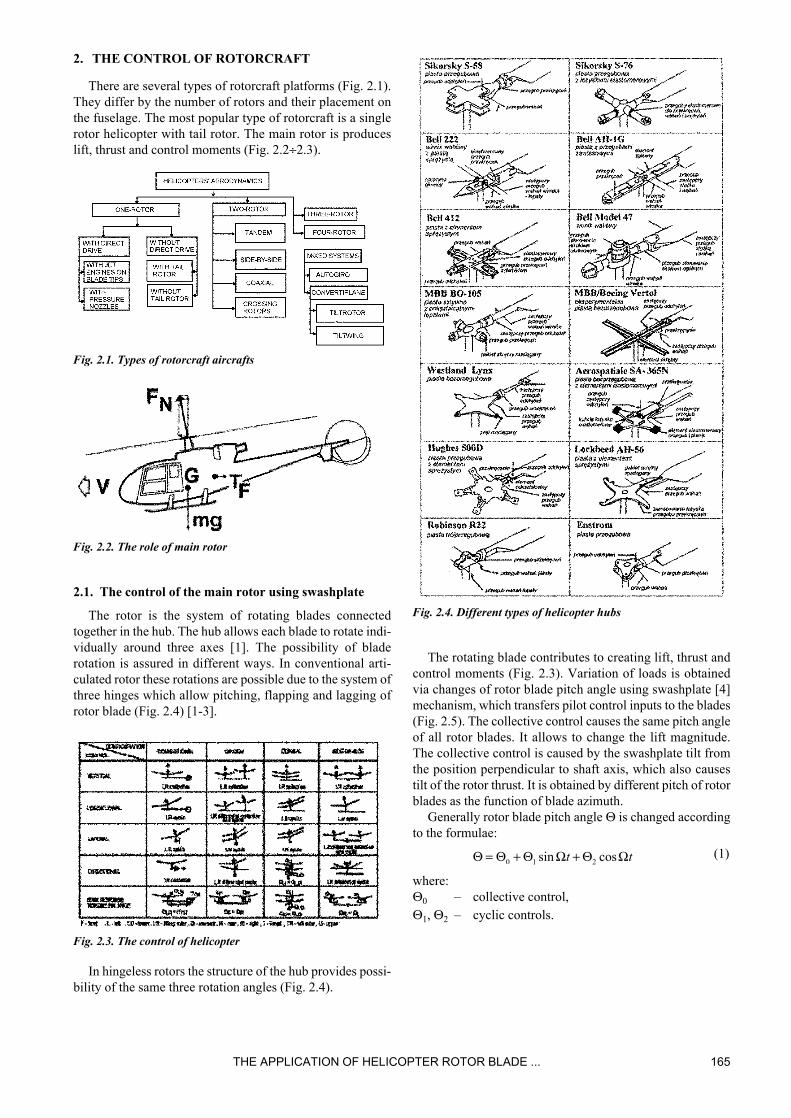
Fig. 3.2. Various types of piezoactuators
Piezoelectric materials can be appled as piezosensors if itcan generate electric voltage when it is subjected to a load(straight piezoelectric effect). It can be also used aspiezoactuator, if it can change its volume (especially lengthin extenders) or shape (in benders) when the electric voltageis applied (reverse piezoelectric effect).
There are many types of piezomaterials andpiezoelements in the market. Many of them are made inlarge quantities, so their prices are not high [54-60] (Fig.3.2).
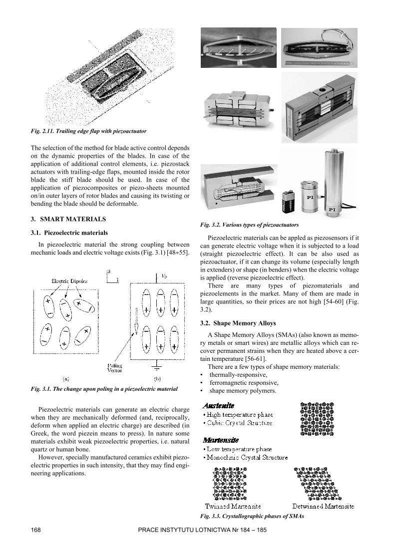
3.2. Shape Memory Alloys
A Shape Memory Alloys (SMAs) (also known as memo-ry metals or smart wires) are metallic alloys which can re-cover permanent strains when they are heated above a cer-tain temperature [56-61].
There are a few types of shape memory materials:• thermally-responsive,• ferromagnetic responsive,• shape memory polymers.
Fig. 3.3. Crystallographic phases of SMAs

THE APPLICATION OF HELICOPTER ROTOR BLADE ... 169
The characteristic feature of all SMAs is the occurrenceof a martensitic phase transformation (Fig. 3.3). The mar-tensitic transformation is a shear-dominant diffusionlesssolidstate phase transformation occurring by nucleation andgrowth of the martensitic phase from a parent austeniticphase. When an SMA undergoes a martensitic phase trans-formation, it transforms from its high-symmetry, usuallycubic, austenitic phase to a low-symmetry martensitic phase,such as the monoclinic variants of the martensitic phase ina NiTi SMA.
The nickel-titanium alloys were first developed in - by theand commercialized under the trade name Nitinol (an acro-nym for Nickel Titanium Naval Ordnance Laboratories).
The range of applications for SMAs has been increasingin recent years, with one major area is medicine: an exampleis development of , that exert a constant pressure on theteeth. There have also been studies on using SMA in robo-tics. Weak point of this technology is energy inefficiency,slow response times, and large .
Metal alloys are not the only thermally-responsive ma-terials, as shape memory polymers have also been develo-ped, having become commercially available in the late1990’s.
There is another type of SMA called (FSMA), thatchange shape under strong magnetic fields. These materialsare of particular interest as the magnetic response tends to bequicker and more efficient than temperature-inducedresponses.
4. TYPES OF SMART ROTORS
There are two main approaches in building smart rotor[39, 40, 62÷116]:• blades with piezocomposites causing its twist along the
span,• blades with trailing edge flaps powered by various active
actuators (SMA, piezobenders, piezostack actuators).
4.1. Controllable rotor blade twist generatedby embedded piezoceramic actuators
Controllable rotor twist can be obtain by:• piezoactuators embedded in rotor blade,• using piezocomposites.
The example for the first way is the smart four-bladedrotor model was built for Boeing-ITR tests [63÷65]. TheNACA0012 blade was made by laminating 10 mm pre-pregfibreglass cloth plies around a foam core at angles 0°/90° inmolds. There were used single-layer and double-layer actu-ators (PZT-5H manufactured by Morgan-Matroc), whichwere grouped in banks of five elements at angles of ±45°respectively on the top and bottom surfaces of the blade (Fig.4.1). During wind tunnel experiments the twist of blade tipof ±0.4° caused by piezo actuation was obtained. That con-cept was later used in full-scale Sikorsky UH-60 rotorsystem [65]. Application of piezoelements caused conside-rable weight increase of 16% of blade weight and bigger tiptwist of ±1-2° was measured (caused by piezo actuation).
Fig. 4.1. Controllable blade twist generated by embedded piezo-ceramic PZT-5H actuators
Another concept [66-70] is based on using piezoelectricactive fiber composites (AFC) embedded in composite rotorblade structures. The active fiber composite actuator utilizesinterdigitated electrode poling (IDE) and piezoelectric fibercomposites (PFC), as shown in Fig. 4.2.
Fig. 4.2. Active Fiber Composite (AFC)
This combination results in a high performance piezo-electric actuator laminate with strength and conformabilitycharacteristics greater than that of a conventional monolithicpiezoceramic. The high conformability of the actuator pac-kage allows it to be embedded easily within nonplanarstructures, much like a traditional composite ply.
Boeing, Sikorsky and the Massachusetts Institute of Tech-nology sponsored by the Defense Advanced Research Pro-jects Agency (DARPA) have successfully completed a pre-liminary hovering flight test of a single model rotor bladeincorporating AFC twist actuation (Fig. 4.3÷4.5). Resultsfrom this test were used to design a four-bladed 1/6 scaleBoeing CH-47D Chinook rotor system (ATR – Active TwistRotor) to examine the performance of the AFCs under full-scale loads (Fig. 4.6). During tests of rotor model the tiptwist of ±1.4° was measured. The application of AFC cau-sed considerable weight increase of 20% of blade weight[66÷70].
Fig. 4.3. Active Fiber Composite in ATR

170 PRACE INSTYTUTU LOTNICTWA Nr 184 – 185
Fig. 4.4. Active Twist Rotor (ATR) blade
Fig. 4.5. Active Twist Rotor (ATR) blade
Fig. 4.6. ATR in wind tunnel
4.2. Trailing-edge flaps actuated with piezo bimorphs
Another idea of the trailing-edge flap actuation is the usingof a piezo bimorph. It is a bending actuator consisting ofpiezoceramic (PZT) sheets, bonded on both sides of a verythin brass shim with an electrically conducting adhesivecoating. The example of a mechanism with the bimorphclamped at one end is presented in Fig. 4.7.
Fig. 4.7. Bimorph actuator in rotor blade section
When equal but opposite electric charges are applied to thePZT sheets, a pure bending of the bimorph occurs. It is acompact actuation device and it generates a small actuationforce. The flap is located near the tip of the blade (Fig. 4.8)and is 20% chord wide. The blade uses NACA 0012 airfoiland has the chord of 0.075 m. The rotor is 1.8 m in diameter.Experiments were made on two - or four-bladed scale rotormodels (ITR-Boeing simulations) [39, 40, 71].
Fig. 4.8. Main rotor blade with flap actuator near the tip
Another system of mechanical hinges and linkages wasused to the amplification of the bending of elements at thetip to cause larger flap rotation (Fig. 4.9) [39]. Commerciallyavailable two-layered G-1195 bimorphs were used andtested on two-bladed rotor model. The maximum flapdeflection amplitude obtained was ±7° for non-rotating rotorand ±1° in case of rotation of 900 rpm in hover.
Fig. 4.9. Piezo bimorph flap actuation system
The application of improved clamping of bimorph actu-ator (Fig. 4.10) allow the increase of the maximum flapdeflection amplitude up to ±8° in case of rotation of 900 rpmin hover [72].
Fig. 4.10. An improved version of bimorph clamping
The increase of the number of piezo layers caused thefurther increase of the maximum flap deflection amplitude[72].
In case of a 8-layered tapered piezo bimorph actuator, themaximum flap deflection amplitude increased up to ±6° incase of rotation of 2150 rpm in hover.
Such an actuator was used in a four-blade rotor model(Fig. 4.11) with Mach scaled hub of Bell-412 [38, 71,73÷76]. The rotor was 1.8 m in diameter. This model wastested in a vacuum chamber but it showed the degradation ofperformance at 2000 rpm. The maximum flap deflection of± 3.2° was achieved.
Fig. 4.11. The blade of a four-bladed rotor model (Bell-412)

THE APPLICATION OF HELICOPTER ROTOR BLADE ... 171
Fig. 4.12. Bell-412 four-blade rotor and fuselage model in theGlenn L. Martin wind tunnel
A two-bladed rotor model with the same hub was testedin hover. This model achieved ±6° to ±10° flap deflectionsin case of 1850 rpm and over oscillatory thrust [71, 73].
Bell-412 four-blade rotor and fuselage model was testedin the wind tunnel (Fig. 4.12) [74]. Flap deflection of ±4° to±5° were achieved at 1800 rpm.
4.3. Trailing-edge flaps actuatedwith piezostack actuators
Piezoceramic stack actuators are often used as a highforce and a relatively small displacement devices [48-55].They are composed of the set of thin piezoceramic layers(sheets) (Fig. 4.13) connected together by conductive adhe-sive. Voltage is applied to the electrodes on both sides of thestack.
Fig. 4.13. Piezostack actuator (Physik Instrumente)
Because of small displacement of piezostack actuatorsmechanical amplification is applied. The most common ideain mechanical amplification is the application of an arm.
First device, called L-arm [38, 74-78] was used in wingmodel (Fig. 4.16÷4.18) which has the chord of 0.2 m and thespan of 0.25 m. A single flap has the chord of 0.04 m and thespan of 0.1 m. There are two high-voltage (1000 V) piezo-stack actuators bonded together back to back installed. Theirfree displacement is 1.5 mm, amplified 10 times. The measu-red value of free displacement was 10 mm (15 mm cal-culated). The linear motion of the piezostack actuator wasconverted to rotary motion of flap using a hinge mechanism.That model was tested in a wind tunnel. The flap amplitudewas ±3° when the flow velocity was 0 m/s and ±1.5° whenvelocity increased to 40 m/s.
Fig. 4.14. Stack and L-arm arrangement
Fig. 4.15. Piezostack actuator with integrated L-arm mechanicalamplification
Fig. 4.16. Wing with trailing-edge flap and L-arm amplification
The amplification mechanism was designed for BoeingMD-900 Explorer [79-81]. It was based on 5 stack actuatorsand a new double-lever (L-L) amplification mechanism (Fig.4.17) which was the developed version of L-arm ampli-fication. A wing section model of chord 0.3 m and span 0.3 mwith the flap of span 0.1 m and chord 0.075 m was built (Fig.4.18, 4.19). The maximum flap amplitude was from ±4° to±20° depending on excitation frequency at the flow velocityof 40 m/s [81].
Fig. 4.17. L-L amplification mechanism

172 PRACE INSTYTUTU LOTNICTWA Nr 184 – 185
Fig. 4.18. Wing section with trailing-edge flap and L-L piezostackamplification system for Boeing MD-900 Explorer
Fig. 4.19. The actuator/flap push-rod attachment
The other amplification mechanism [82, 83] was desig-ned for Boeing MD-900 Explorer five-blade rotor system of11 m in diameter. This actively controlled rotor was used forvibrations, noise and performance tests. The new amplifi-cation system was based on 4 piezostack actuators (piezo-ceramic/lead magnesium niobate stack, low-voltage, co-fi-red PMN:PZ by Xinetics). The large deflection was suppliedby bi-axial arrangement of two long stack columns operatingin push-pull mode in conjunction with L-shaped lever andflexural mount (Fig. 4.20). The expected flap amplitude of± 4° at excitation frequency 40 Hz was not realised.
Fig. 4.20. Bi-axial piezostack flap actuator
The next type of discrete trailing-edge servo-flap actuatorcalled X-frame actuator (Fig. 4.21÷4.23) was designed forthe 1/6th Mach scale rotor model of Boeing CH-47DChinook [84÷87].
Fig. 4.21. X-frame actuator
The actuator consists of two active high-voltage piezo-stacks and two criss-cross frames. Amplification is achievedvia shallow angle arrangement. During tests at the tip Mach0.63 and 8° collective pitch, oscillatory flap deflections±2.4° were achieved for excitation voltage of ±1000 V. Theactuator was tested in full-scale rotor system of MD-900Explorer and scaled rotor model of Eurocopter EC-135.
Fig. 4.242 The schema of control system with X-frame actuator
Fig. 4.23. X-frame actuator in CH-47D rotor blade
Similar mechanism composed of piezostack actuator wasalso used in [88, 89] to control leading-edge flap.
Similar mechanism was used by ONERA and Eurocopterduring their experiments. They used low-voltage (200 V)piezostack Cedrat actuator APA (Amplified Piezo Actuator)series (APA230, APA500L, APA750X) [45÷48]. Theseactuators have the shape of composite frame (elliptical) (Fig.4.24) which allows to be centered easier than X-frame orL-L frame actuators.
Fig. 4.24. Amplified Piezo Actuator (APA) actuators from Cedrat
The segment of Rotor à Pales Actives (RPA) blade (Fig.4.25÷4.28) was built. During experiments the flap deflec-tions of -2.5°+3.5° were measured.

THE APPLICATION OF HELICOPTER ROTOR BLADE ... 173
Fig. 4.25. The Rotor à Pales Actives (RPA) blade with flaps actu-ated by APA
Fig. 4.26. The Rotor à Pales Actives (RPA) blade with flaps actu-ated by APA
Recently full-scale rotor (Fig. 4.27, 4.28) was build byEurocopter and tested in hover stand and in flight (Euro-copter BK-117).
Fig. 4.27. Eurocopter BK-117 smart rotor in test stand
4.4. Trailing edge flap actuated withmagnetostrictive actuators andextension-torsion coupled composite tube
The idea of using the extension-torsion coupled com-posite tube [90, 91] working in conjunction with magne-tostrictive actuator was also tested. (Fig. 4.29).
Fig. 4.29. Rotor blade with trailing edge flap actuated with mag-netostrictive actuators and extension-torsion coupled compositetube
The extension-torsion coupled composite tube was sub-jected to an axial force generated by a magnetostrictiveactuator that induces the twisting of the tube. The extension-torsion coupled composite beam was built by wrappingangle plies resulting in an antisymmetric ply lay-up withrespect to the beam axis. To utilise the extension-torsioncoupling of the composite tube, the magnetostrictive actu-ator must be attached to the tube in such a way that bothtwist and axial strain is permitted freely (Fig. 4.30). Duringtests Kevlar-epoxy tube / piezoelectric stack systems of0.5 m length generated ±5.2° of flap deflection. Such a sys-tem can be used for vibration control but because of pooroverall structural efficiency of extension-torsion coupledtubes appears less useful than other actuation systems.
Fig. 4.28. Eurocopter BK-117with smart rotor

174 PRACE INSTYTUTU LOTNICTWA Nr 184 – 185
Fig. 4.30. Schema of composite tube and magnetostrictive actu-ator assembly
4.5. Trailing edge flap actuated withpiezoceramic actuators and tailoredbending-torsion coupled composite beam
A piezo-induced bending-torsion coupled compositebeam was also used for trailing-edge flap deformations (Fig.4.31) [92] or twisting the blade tip (Fig. 4.32) [93÷95].
Fig. 4.31. Trailing edge flap actuated with piezoceramic actuatorsand tailored bending-torsion coupled composite beam
Fig. 4.32. Blade tip actuated with bending-torsion actuator
The beam is divided into the number of spanwise seg-ments with reversed bending-torsion coupling for each suc-cessive segment. the same piezoceramic actuators are bon-ded on each beam segment on the top and bottom surfacesresulting in an equivalent bimorph unit (Fig. 4.33). An exci-tation generates a sinusoidal spanwise bending, where asinduced twist is additive in the spanwise direction.
Fig. 4.33. Composite bending-torsion beam
A 2-bladed Mach-scaled rotor model with blades withflaps at 90% of radius was tested and the maximum flapdeflection of ± 4° was achieved.
A 4-bladed Mach-scale rotor model with hub of Bell-412[94, 95] with 10% tip was tested. For an 125 V actuation themeasured tip deflection was between ±1.2° and ±1.6° (Fig.4.34).
Fig. 4.34. A 4-bladed Mach-scale rotor model with hub of Bell--412 with 10% tips
4.6. Shape Memory Alloys actuators
Shape Memory Alloys (SMA) can generate the biggestforces from all smart materials but they work with the fre-quencies of order of 1 Hz which limits their application tothe static case. The strains can be quite large, i.e., in case ofmoderate increase of Nitinol temperature up to 120°F thedeflection can be even 6% [96÷101].
The potential application of SMA in aerospace systemsmay be to adjust trailing-edge trim-tab of a helicopter rotorfor in-flight tracking.
Few concepts of using of SMA were investigated. TwoSMA rods deflecting a blade airfoil (Fig. 2.10, Fig. 4.35)were used: the first one as actuator, and the second one asa restoring spring. There were the concept of using SMAplates (Fig. 4.36) [102, 103] or beams [104÷108].
Fig. 4.35. SMA rods in rotor blade

THE APPLICATION OF HELICOPTER ROTOR BLADE ... 175
Fig. 4.36. SMA plates on rotor blade
Using SMA wires the segment of rotor blade with con-trolled trailing-edge flap was built. The flap was deflected bythe system of from 2 to 5 Nitinol wires of diameter 0.005 m(Fig. 4.37, 4.38). During the tests the tab deflections of 20°were obtained in wind tunnel when a inflow was 40 m/s[109÷111].
Fig. 4.37. Blade with SMA wires
Fig. 4.38. The segment of rotor blade with 3 SMA wires
SMA Trim Actuator (SMART) was used for actuating oftrailing-edge flap on Boeing MD-900 Explorer (Fig. 4.39)[112÷116]. It was used to adjust trailing-edge trim-tab on a he-licopter rotor for in-flight blades tracking. Also a doubledX-frame piezostack actuator deflecting a trailing-edge flapwas used for blade active control for noise and vibration(Fig. 4.40).
Fig. 4.39. MD-900 rotor blade with control surfaces actuated bySMART and X-Frame
Fig. 4.40. Doubled X-frame actuator controlling a trailing-edgeflap in MD-900 rotor blade
The trim-tab was located at 72% radial position and wasdeflected by SMA torsional actuator developed by Memry(Fig. 4.41). The locking mechanism was designed to keepthe tab in position without power to the actuator. It wasdesigned to undergo ±7.5° in steps of 0.25°.
Fig. 4.41. SMART Trim Actuator used for deflecting of trim-tab
REFERENCES
[1] Szabelski K., Jancelewicz B., £ucjanek W.: Wstêpdo konstrukcji œmig³owców. WKi£. Warszawa 1995.
[2] Johnson W.: Helicopter Theory. Princeton UniversityPress, 1980.
[3] Bramwell A. R. S.: Helicopter Dynamics. EdwardArnold, London, 1976.
[4] Prouty R. W.: Helicopter Performance, Stability andControl. PWS Engineering, Boston, 1986.
[5] Reichert G., Huber H.: Active Control of HelicopterVibration. Fourth Workshop on Dynamic and Aero-elastic Stability Modeling of Rotorcraft Systems, Uni-versity of Maryland, College Park, Maryland,November 19-21, 1991.
[6] Friedmann P. P.: Rotary-Wing AeroservoelasticProblems. AIAA Paper 91-121070, 1992.
[7] Friedmann P. P., Millott T. A.: Vibration Reductionin Rotorcraft Using Active Control: A Comparison ofVarious Approaches. AIAA Journal of Guidance, Con-trol and Dynamics, Vol. 18, No. 4, July-August 1995.
[8] De Vivo L., Concilio A.: Active Control on TypicalHelicopter Panels by Using Piezo-Actuators. ICAS1996, Sorrento, Italy.
[9] Lockyer A. J., Kudva J. N., Kane D. M., Hill B. P.,Martin C. A.: A Qualitative Assessment of SmartSkins and Avionics Structures Integration. SPIE Vol.2189, 1994.

176 PRACE INSTYTUTU LOTNICTWA Nr 184 – 185
[10] Staple A. E., Wells D. M.: The Development of anActive Control of Structural Response System for EH101 Helicopter. Paper No. III.6.1.1., 16th EuropeanRotorcraft Forum, Glasgow, UK, September 1990.
[11] Kloppel T. D., Richter P.: Development of ActiveControl Technology in the Rotating System, FlightTesting and Theoretical Investigations. Paper No. 89,I-06, 18th European Rotorcraft Forum, Avignon,France, September 15-18, 1992.
[12] Nitzsche F.: A New Individual Blade Control Appro-ach to Attenuate Rotor Vibration. 22nd European Ro-torcraft Forum, Brighton, UK, September 1996.
[13] Nitzsche F., Breitbach E.: The Smart Structures Tech-nology in the Vibration Control of Helicopter Blades inForward Flight. First European Conference on SmartStructures and Materials, Glasgow, UK, 1992.
[14] Tylikowski A.: Stabilisation of Beam Parametric Vib-rations. Journal of Theoretical and Applied Mecha-nics, 3, 31, 1993.
[15] Wereley N. M.: Active Damping of Flexible RotorBlades Using ER Fluid Based Actuators. SPIE NorthAmerican Conference on Smart Structures andMaterials, Orlando, FL, USA, Vol. 2190, pp. 13-18,February 1994.
[16] Kamath G. M., Wereley N. M.: Distributed Dampingof Rotorcraft Flexbeams Using ElectrorheologicalFluids. AIAA-95-1082-CP, AIAA/ASME AdaptiveStructures Forum, New Orleans, LA, USA, April 1995.
[17] Rotor & Wing. May 1996.[18] Aviation Week & Space Technology, April 15, 1996.[19] Chattopadhyay A., Seely C. E.: A Multiobjective
Optimization Procedure for the Design of RotatingComposite Box Beams with Discrete PiezoelectricActuators. SPIE Conference on Smart Structures andIntelligent Systems, Vol. 2190, 1994.
[20] Chopra I.: Development of Smart Rotor. Paper No.N6, 19th European Rotorcraft Forum, Cernobbio (Co-mo), Italy, September 14-16, 1993.
[21] Chopra I.: Status of Application of Smart StructuresTechnology to Rotorcraft Systems. Proceedings of in-novation in Rotorcraft Technology, Royal Aerona-utical Society, May 1997.
[22] Prasad J. V. R., Sankar L. N., Park W. G., OrbanJ. E.: Active Control of Rotor Noise. SPIE Vol. 1917,Smart Structures and Intelligent Systems, 1993.
[23] Hanagud S., Roglin R. L., Nagesh Babu G. L.:Smart Airfoils for Helicopter Control. Paper No. 119(H04), 18th European Rotorcraft Forum, Avignon,France, September 15-18, 1992.
[24] Geissler W., Raffel M.: Dynamic Stall Control byAirfoil Deformation. Paper No. C1, 19th European Ro-torcraft Forum, Cernobbio (Como), Italy, September14-16, 1993.
[25] Roglin R. L., Hanagud S.: A Helicopter with Adap-tive Rotor with Tip Mounted Active Flaps. 50th Ame-rican Helicopter Society Forum, 1994.
[26] Dawson S., Straub F.: Design, Validation and Test ofa Model Rotor with tip Mounted Active Flaps. 50thAmerican Helicopter Society Forum, 1994.
[27] Dawson S., Marcolini M., Booth E., Straub F.: WindTunnel Test of an Active Flap Rotor: BVI Noise andVibration Reduction. 51st American Helicopter So-ciety Forum, Fort Worth, TX, USA, May 9-11, 1995.
[28] Straub F. K.: Active Flap Control for Vibration Re-duction and performance Improvement. 51st AmericanHelicopter Society Forum, Fort Worth, TX, USA, May9-11, 1995.
[29] Charles B., Tadghighi H., Hassan A.: Higher Har-monic Actuation of Trailing-Edge Flaps for Rotor BVINoise Control. 52nd American Helicopter SocietyForum, Washington, DC, USA, June 4-6, 1996.
[30] Straub F. K., Hassan A. A.: Aeromechanic Consid-erations in the Design of a Rotor with Smart MaterialActuated Trailing Edge Flaps. 52nd American He-licopter Society Forum, Washington, DC, USA, June4-6, 1996.
[31] Millot T. A., Friedmann P. P.: Vibration Reductionin Helicopter Rotors Using an Active Control SurfaceLocated on the Blade. AIAA-92-2451-CP, 33rdAIAA/ASME/AHS/ASC Structures, Structural Dyna-mics and Material Conference, Dallas, TX, USA,April 13-15, 1992.
[32] Millot T. A., Friedmann P. P.: The Practical Imple-mentation of an Actively Controlled Flap to ReduceVibrations in Helicopter Rotors. pp. 1079-1092, 49thAmerican Helicopter Society Forum, St. Louis, MO,USA, May 1993.
[33] Millot T. A., Friedmann P. P.: Vibration Reductionin Hingeless Rotors Using an Actively ControlledTrailing Edge Flap: Implementation and TimeDomain Simulation. AIAA-94-1306-CP, 35th AIAA//ASME/ASCE/AHS/ASC Structures, Structural Dyna-mics and Material Conference, Dallas, TX, USA,April 1994.
[34] Narkiewicz J., Ling A., Done G. T. S.: UnsteadyAerodynamic Loads on an Aerofoil with a DeflectingTab. Aeronautical Journal, Vol. 99, No. 987, pp. 282-292, September/October 1995.
[35] Yillikci Y. K., Hanagud S., Aygun C., KaramisirT.: Modeling Nonlinear Response of Hingeless RotorBlades With Flaps Controls. 22nd European Rotor-craft Forum, Brighton, UK, September 1996.
[36] Yillikci Y. K., Hanagud S.: An Initial Evaluation ofBlade Dynamics of a Stopped/Flipped Rotor with FlapControls. Paper No. D15, 19th European RotorcraftForum, Cernobbio (Como), Italy, September 14-16,1993.
[37] Roglin R. L., Hanagud S., Peters D. A., Chattopa-dhyay A.: Optimization of the Twist Distribution Usingan Adaptive Airfoil. 52nd American Helicopter SocietyForum, Washington, DC, USA, June 4-6, 1996.
[38] Loewy R. G., Tseng S. P.: Tests of an Unstable Lif-ting Surface Stabilized by a Simulated Smart Struc-ture. Presentation at 6th International Workshop onDynamics and Aeroelastic Stability Modeling ofRotorcraft Systems, November 8-10, 1995.
[39] Spangler R. L. Jr, Hall S. R.: Piezoelectric Actuatorsfor Helicopter Rotor Control. AIAA-90-1076-CP, Part3, pp. 1589-1599, 31st AIAA/ASME/ASCE/AHS/ASCStructures, Structural Dynamics and Material Con-ference, Long Beach, CA, USA, April 2-4, 1990.
THE APPLICATION OF HELICOPTER ROTOR BLADE ... 177
[40] Ben-Zeev O., Chopra I.: Advances in the Deve-lopment of an Intelligent Helicopter Rotor EmployingSmart Trailing-Edge Flaps. Smart Materials andStructures, Vol. 5, No. 1, pp. 11-25, February 1996.
[41] Samak D. K., Chopra I.: Design of High Force, HighDisplacement Actuators for Helicopter Rotor. SPIEConference on Smart Structures and Intelligent Sys-tems, Vol. 2190, 1994, Smart Materials and Structures,Vol. 5, No. 1, pp. 58-67, February 1996.
[42] Straub F. K., Merkley D. J.: Design of a Servo-FlapRotor for Reduced Control Loads. Smart Materials andStructures, Vol. 5, No. 1, pp. 68-75, February 1995.
[43] Giurgiutiu V., Chaudhry Z., Rogers C. A.: Engine-ering Feasibility of Induced Strain Actuators for RotorBlade Active Vibration Control. SPIE Vol. 2190, Jo-urnal of Intelligent Materials Systems and Structures,Vol. 6, September 1995.
[44] Narkiewicz J.: Sterowanie dodatkowe wirop³atówprzy wykorzystaniu koncepcji uk³adów inteligentnych.Zeszyty Naukowe Politechniki Warszawskiej, SeriaMechanika, Zeszyt Nr 169, Oficyna Wydawnicza Poli-techniki Warszawskiej, Warszawa, 1998.
[45] Petitniot J-L., des Rochettes H-M., Leconte P.:Experimental Assessment and Further Development ofAmplified Piezo Actuators for Active Flap Devices.Paper No. B 3.4, ACTUATOR 2002, 8th InternationalConference on New Actuators, Bremen, Germany,June 10–12, 2002.
[46] des Rochettes H-M., Leconte P.: Experimental asses-sment of an active flap device. 58th American Helico-pter Society Forum, Montréal, Quebec, Canada, June11-13, 2002.
[47] Kloeppel V., Enenkl B.: Rotor Blade Control by Acti-ve Helicopter Servo Flaps. International Forum onAeroelasticity and Structural Dynamics 2005, Muen-chen, Germany, June 28 –July 01, 2005.
[48] CEDRAT TECHNOLOGIES, www.cedrat.com,[49] Dynamic Structures & Materials,
www.dynamic-structures.com,[50] Physik Instrumente, www.pi.ws.[51] EDO Corporation, www.edoceramic.com.[52] Material Systems Inc., www.matsysinc.com.[53] Morgan Matroc (Morgan Electro Ceramics),
www.morganelectroceramics.com.[54] Piezo Systems Inc., www.piezo.com.[55] Miller M.: The State of Art in Helicopter Active Control
Systems. Report No. 207/BA/05/D, December 2005.[56] Wikipedia, www.wikipedia.com.[57] Nitinol Devices & Components, www.nitinol.com.[58] Johnson Matthey, www.jmmedical.com.[59] MIDE Technology Corporation, www.mide.com.[60] Duerig T. W., Melton K. N., Stöckel D., Wayman
C. M.: Engineering Aspects of Shape Memory Alloys.ISBN 0-750-61009-3, London, Butterworth Heine-mann, 1990.
[61] Miller M.: The Application of Shape Memory Alloys inHelicopters. Report No. 210/BA/06/D, August 2006.
[62] Chopra I.: Recent Progress on the Development of aSmart Rotor System. 26th European Rotorcraft Forum,the Hague, the Netherlands, September 2000.
[63] Chen P. C., Chopra I.: Induced Strain Actuation ofComposite Beams and Rotor Blades with EmbeddedPiezoceramic Elements. Smart Materials and Structu-res, Vol. 5, No. 1, pp. 35-48, February 1996.
[64] Chen P. C., Chopra I.: Hover Testing of Smart Rotorwith Induced-Strain Actuation of Blade Twist. AIAAJournal, Vol. 35, No. 1, pp. 6-16, January 1997.
[65] Chen P. C., Chopra I.: Wind Tunnel Test of a SmartRotor with Individual Blade Twist Control. Journal ofIntelligent Material Systems and Structures, Vol. 8,No. 5, pp. 414-425, May 1997.
[66] Gentilman R., McNeal K., Schmidt G., PizzocheroA., Rossetti G. A. Jr.: Enhanced performance activefiber composites. SPIE 10th International Symposiumon Smart Structures and Materials, March 2003.
[67] Rodgers J. P., Hagood N. W.: Design and Manu-facture of an Integral Twist-Actuated Rotor Blade. Pro-ceedings of the 38th AIAA/ASME/ASCE/AHS/ASCStructures, Structural Dynamics and Materials Con-ference and Adaptive Structures Forum, Kissimmee,FL, USA, April 1997.
[68] Derham R. C., Hagood N. W.: Rotor Design UsingSmart Materials to Actively Twist Blades. 52nd Ame-rican Helicopter Society Forum, Washington, DC,USA, June 4-6, 1996.
[69] Rodgers J. P., Hagood N. W.: Preliminary Mach-Scale Hover Testing of an Integral Twist-Actuated Ro-tor Blade. Proceedings of the 1997 SPIE’s North Ame-rican Symposium on Smart Structures and Materials,San Diego, CA, USA, March 1997.
[70] Rodgers J. P., Hagood N. W.: Development of anIntegral Twist-Actuated Rotor Blade for IndividualBlade Control. MIT ASML 98-6, October 1998.
[71] Koratkar N., Chopra I.: Analysis and Testing of MachScaled Rotor Model with Piezoelectric Bender ActuatedTrailing-Edge Flaps for Helicopter Vibration Control.Proceedings of the 40th AIAA/ASME/ASCE/AHS/ASCStructures, Structural Dynamics and Materials Confe-rence and Adaptive Structures Forum, St. Louis, MO,USA, April 1999.
[72] Koratkar N. A., Chopra I.: Analysis and Testing ofFroude Scaled Helicopter Rotor with PiezoelectricBender Actuated Trailing Edge Flaps. Journal of In-telligent Material Systems and Structures, Vol. 8, pp.555-570, July 1997.
[73] Koratkar N. A., Chopra I.: Design, Fabrication andTesting of a Mach Scaled Rotor Model with Trailing-Edge Flaps. 55th American Helicopter Society Forum,Montréal, Quebec, Canada, May 1999.
[74] Koratkar N. A., Chopra I.: Wind Tunnel Testing ofa Mach Scaled Rotor Model with Trailing-Edge Flaps.56th American Helicopter Society Forum, VirginiaBeach, VA, USA, May 2000.
[75] Hall S. R., Prechtl E. F.: Development of a Piezo-electric Servoflap for Helicopter Rotor Control. SmartMaterials and Structures, Vol. 5, No. 1, pp. 26-34, Fe-bruary 1996.
[76] Fulton M. V., Ormiston R. A.: Small-Scale RotorExperiments with On-Blade Elevons to Reduce BladeVibratory Loads in Forward Flight. 54th AmericanHelicopter Society Forum, Washington, DC, USA,May 1998.

178 PRACE INSTYTUTU LOTNICTWA Nr 184 – 185
[77] Spencer B., Chopra I.: Advances in the Developmentof an Intelligent Helicopter Rotor Employing SmartTrailing-Edge Flaps. Proceedings of the 1996 SPIE’sNorth American Symposium on Smart Structures andMaterials, San Diego, CA, USA, February 1996.
[78] Chandra R., Chopra I.: Actuation of Trailing EdgeFlap in Wing Model Using Piezostack Device. Pro-ceedings of the 38th AIAA/ASME/ASCE/AHS/ASCStructures, Structural Dynamics and Materials Con-ference and Adaptive Structures Forum, Kissimmee,FL, USA, April 1997.
[79] Lee T., Chopra I.: Design and Spin Testing of an Ac-tive Trailing Edge Flap Actuated Piezostacks. Pro-ceedings of the AIAA/ASME/ASCE/AHS/ASC Struc-tures, Structural Dynamics and Materials Conferenceand Exhibit, St. Louis, MO, USA, April 1999.
[80] Lee T., Chopra I.: Development and Validation ofa Refined Piezostack-Actuated Trailing Edge Flap Actu-ator for a Helicopter Rotor. Proceedings of the 1999SPIE’s North American Symposium on Smart Struc-tures and Materials, Newport Beach, CA, USA, March1999.
[81] Lee T., Chopra I.: High Displacement PiezoelectricTrailing-Edge Flap Mechanism for Helicopter Rotors.Ph.D. Dissertation, University of Maryland, CollegePark, MD, USA, December 1999.
[82] Straub F. K., King R. J.: Application of Smart Ma-terials to Control of a Helicopter Rotor. Proceedingsof the 1996 SPIE’s North American Symposium onSmart Structures and Materials, San Diego, CA, USA,February 1996.
[83] Straub F. K., Ngo H. T., Anand V., Domzalski D. B.:Development of a Piezoelectric Actuator for TrailingEdge Flap Control of Rotor Blades. Proceedings of the1999 SPIE’s North American Symposium on SmartStructures and Materials, Newport Beach, CA, USA,March 1999.
[84] Prechtl E. F., Hall S. R.: Design of a High-EfficiencyDiscrete Servo-Flap Actuator for helicopter RotorControl. Proceedings of the 1997 SPIE’s North Ame-rican Symposium on Smart Structures and Materials,San Diego, CA, USA, March 1997.
[85] Hall S. R., Prechtl E. F.: Preliminary Testing of aMach-Scaled Active Rotor Blade with a Trailing-EdgeServo-Flap. Proceedings of the 1999 SPIE’s NorthAmerican Symposium on Smart Structures and Ma-terials, Newport Beach, CA, USA, March 1999.
[86] Schimke D., Janker V., Blaas A., Kube R., KesslerC.: Individual Blade Control by Servo-Flap and BladeRoot Control, A Collaborative Research and Develop-ment Programme. 23rd European Rotorcraft Forum,Dresden, Germany, September 1997.
[87] Schimke D., Janker V., Wendt V., Junker B.: WindTunnel Evaluation of a Full Scale Piezoelectric FlapControl Unit. 24th European Rotorcraft Forum, Mar-seille, France, September 1998.
[88] Shaner M.: Active Blade Leading-Edge Droop withPiezostack for High Speed Noise Suppression. MScThesis, University of Maryland, College Park, MD,USA, January 2000.
[89] Janker P., Kloppel V., Hermle T., Lorkowski T.,Storm S., Christmann M., Wettemann A.: Deve-lopment and Evaluation of a Hybrid PiezoelectricActuator for Advanced Flap Control Technology.25th European Rotorcraft Forum, Rome, Italy, Sep-tember 1999.
[90] Chandra R., Chopra I.: Structural Response ofComposite Beams and Blades with Elastic Cou-plings. Composite Engineering, Vol. 2, No. 5, pp.347-374, 1992.
[91] Bothwell C. M., Chandra R., Chopra I.: TorsionalActuation with Extension-Torsional Composite Cou-pling and Magnetostrictive Actuators. AIAA Jour-nal, Vol. 33, No. 4, pp. 723-729, April 1995.
[92] Bernhard A., Chopra I.: Trailing Edge Flap Acti-vated by a Piezo-Induced Bending-Torsion CoupledBeam. Journal of the American Helicopter Society,Vol. 44, No. 1, pp. 3-15, January 1999.
[93] Bernhard A., Chopra I.: Development of a SmartMoving Blade Tip Activated by a Piezo-InducedBending-Torsion Coupled Beam. 53rd AmericanHelicopter Society Forum, Virginia Beach, VA,USA, May 1997.
[94] Bernhard A., Chopra I.: Mach-Scale Design ofa Rotor-Model with Active Blade Tip. 55th Ameri-can Helicopter Society Forum, Montréal, Quebec,Canada, May 1999.
[95] Bernhard A.: Smart Helicopter Rotor with ActiveBlade Tips (SABT). Ph.D. Dissertation, AerospaceEngineering, University of Maryland, College Park,MD, USA, March 2000.
[96] Epps J. J., Chopra I.: Comparative Evaluation ofShape Memory Alloy Constitutive models with TestData. Proceedings of the 38th AIAA/ASME//ASCE//AHS/ASC Structures, Structural Dynamics andMaterials Conference and Adaptive Structures Fo-rum, Kissimmee, FL, USA, April 1997.
[97] Tanaka K.: Thermomechanical Sketch of ShapeMemory Effect: One-dimensional Tensile Beha-viour. Res. Mechanica, Vol. 18, pp. 251-263, 1986.
[98] Liang C., Rogers C. A.: One-Dimensional Thermo-mechanical Constitutive Relations for Shape Memo-ry Material. Journal of Intelligent Materials andStructures, Vol. 1, pp. 207-234, April 1990.
[99] Brinson L. C.: One Dimensional Constitutive Beha-vior of Shape Memory Alloys: Thermo-mechanicalDerivation with Non-Constant Material Functions.Journal of Intelligent Material Systems and Struc-tures Vol. 4, No. 2, p. 229-242, 1993.
[100] Boyd J. G., Lagoudas D. C.: A ThermodynamicConstitutive Model for the Shape Memory Mater-ials. Part I. The Monolithic Shape Memory Alloys.International Journal of Plasticity, Vol. 12, No. 6,pp.805-842, 1996.
[101] Prahlad H., Chopra I.: Experimental Character-ization of Ni-Ti Shape Memory Alloy Wires underComplex Loading Conditions. Proceedings of the1999 SPIE’s North American Symposium on SmartStructures and Materials, Newport Beach, CA, USA,March 1999.
THE APPLICATION OF HELICOPTER ROTOR BLADE ... 179
[102] Rogers C. A., Liang C., Jia J.: Behavior of ShapeMemory Alloy Reinforced Composite Plates, Part I:Model Formulations and Control Concepts. Pro-ceedings of the 30th AIAA/ASME/ASCE/AHS//ASC Structures, Structural Dynamics and MaterialsConference, Washington D.C., USA, April 1989.
[103] Rogers C. A., Liang C., Jia J.: Behavior of ShapeMemory Alloy Reinforced Composite Plates, Part II:Results. Proceedings of the 30th AIAA/ASME/ASCE//AHS/ASC Structures, Structural Dynamics and Ma-terials Conference, Washington D.C., USA, April1989.
[104] Rogers C. A., Barker D. K.: Experimental Studiesof Active Strain Energy Tuning of Adaptive Com-posites. Proceedings of the 31st AIAA/ASME/ASCE//AHS/ASC Structures, Structural Dynamics andMaterials Conference, Washington D.C., USA,April 1990.
[105] Baz A., Imam K., McCoy J.: Active Vibration Con-trol of Flexible Beams Using Shape Memory Actu-ators. Journal of Sound and Vibration, Vol. 140 (3),pp. 437-456, 1990.
[106] Baz A. Ro S.: Thermo-Dynamic Characteristics ofNitinol-Reinforced Composite Beams. CompositeEngineering, Vol. 2, No. 5-7, pp. 527-542, 1992.
[107] Epps J. J., Chandra R.: Shape Memory AlloyActuation for Active Tuning of Composite Beams.Proceedings of the 1995 SPIE’s North AmericanSymposium on Smart Structures and Materials, SanDiego, CA, USA, February 1995.
[108] Epps J. J., Chandra R.: Shape Memory AlloyActuation for Active Tuning of Composite Shafts.Proceedings of the 1996 SPIE’s North AmericanSymposium on Smart Structures and Materials, SanDiego, CA, USA, February 1996.
[109] Liang C., Schroeder S., Davidson F. M.: Appli-cation of Torsion Shape Memory Alloy Actuators forActive Rotor Blade Control: Opportunities and Lim-itations. Proceedings of the 1996 SPIE’s NorthAmerican Symposium on Smart Structures andMaterials, San Diego, CA, USA, February 1996.
[110] Kudva J. et al.: Overview of the DARPA/AFRL/NASASmart Wing Program. Proceedings of the 1999SPIE’s North American Symposium on Smart Struc-tures and Materials, Newport Beach, CA, USA,March 1999.
[111] Roglin R. L., Hanagud S. V.: A Helicopter withAdaptive rotor Blades for Collective Control. SmartMaterials and Structures, Vol. 5, No. 1, pp. 1-10,February 1995.
[112] Straub F. K., Ealey M. A., Schetky L. McD.:Application of Smart Materials to Helicopter ActiveControl. Proceedings of the 1997 SPIE’s NorthAmerican Symposium on Smart Structures and Ma-terials, San Diego, CA, USA, March 1997.
[113] Epps J. J., Chopra I.: Shape Memory AlloyActuators for In-Flight Tracking of Helicopter RotorBlades. Proceedings of the 1998 SPIE’s NorthAmerican Symposium on Smart Structures and Ma-terials, San Diego, CA, USA, March 1998.
[114] Epps J. J., Chopra I.: In-Flight Tracking of He-licopter Rotor Blades Using Shape Memory AlloyActuators. Proceedings of the 40th AIAA /ASME//ASCE/AHS/ASC Structures, Structural Dynamicsand Materials Conference and Adaptive StructuresForum, St. Louis, MO, USA, April 1999.
[115] Epps J. J., Chopra, I.: Methodology of In-FlightTracking of Helicopter Rotor Blades Using ShapeMemory Alloy Actuators. 55th American HelicopterSociety Forum, Virginia Beach, VA, USA, May 1999.
[116] Epps J. J.: In-Flight Tracking of Helicopter RotorBlades with Tabs actuated with Shape Memory AlloyActuators. Ph.D. Dissertation, Aerospace Engine-ering, University of Maryland, MD, USA, February2000.
M. Miller, W. Kania, T. Czechyra, J. Narkiewicz
ZASTOSOWANIE UK£ADÓW AKTYWNEGOSTEROWANIA £OPAT WIRNIKA NOŒNEGO
ŒMIG£OWCA W REDUKCJI HA£ASU I DRGAÑORAZ POPRAWY OSI¥GÓW
StreszczenieW artykule przedstawiono mo¿liwoœci wykorzystania
aktywnego sterowania ³opat wirnika noœnego œmig³owca doredukcji ha³asu i drgañ oraz poprawy osi¹gów. Prace w za-kresie opracowywania nowych, cichych i efektywnych podwzglêdem osi¹gów aerodynamicznych i sterowania wirni-ków noœnych œmig³owców s¹ prowadzone praktycznie przezwiêkszoœæ oœrodków badawczych oraz wytwórców œmig-³owców na œwiecie. W³asnoœci wirnika noœnego w najwiêk-szym stopniu decyduj¹ o parametrach eksploatacyjnych ca-³ego œmig³owca: osi¹gach, manewrowoœci, poziomie drgañi ha³asu, jakoœci sterowania, itd. Jednym ze sposobów popra-wy osi¹gów wirnika noœnego jest zastosowanie uk³aduaktywnego sterowania ³opat wirnika noœnego œmig³owca.Badania nad takimi rozwi¹zaniami s¹ obecnie prowadzoneprzez przemys³ lotniczy na œwiecie (Eurocopter, Boeing)(rys. 1). S¹ one tak¿e tematem projektów w ramach europej-skich programów badawczych (FRIENDCOPTER). Uk³adyaktywnego sterowania s¹ konstruowane z wykorzystaniemró¿norodnych materia³ów inteligentnych, które dzia³aj¹ jakoczujniki i/lub si³owniki, co pozwala na szybkie dostosowa-nie sterowania do zmieniaj¹cych siê warunków pracy stero-wanego uk³adu. Najczêœciej stosowane materia³y piezoelek-tryczne s¹ wbudowywane w konstrukcjê ³opaty jako modu³yz piezosi³ownikami lub piezokompozyty. W zale¿noœci odsposobu zabudowy wielkoœci¹ sterowan¹ jest k¹t wychyle-nia klapki lub odkszta³canie segmentu ³opaty w celu zmianyjego k¹t skrêcenia. W zale¿noœci od miejsca zamocowaniamateria³ów inteligentnych aktywne sterowanie dotyczy ca³ej³opaty lub tylko jej zewnêtrznej czêœci.

180 PRACE INSTYTUTU LOTNICTWA Nr 184 – 185
М. Миллер, В. Каня, Т. Чехыра
ПРИМЕНЕНИЕ СИСТЕМ АКТИВНОГОУПРАВЛЕНИЯ ЛОПАСТЕЙ НЕСУЩЕГО
ВИНТА ВЕРТОЛЕТА ДЛЯ УМЕНЬШЕНИЯШУМА И КОЛЕБАНИЙ, А ТАКЖЕУЛУЧШЕНИЯ ХАРАКТЕРИСТИК
Резюме
В статье представлена возможность использова1ния активного управления лопастей несущего винтадля уменьшения шума в колебаний, а также улучше1ния характеристик. Работы в области разработки но1вых, тихих и эффективных в отношении аэродинами1ческих характеристик и направления несущихвинтов вертолетов проводятся практически в боль1шинстве исследовательских центров и вертолето1строительных заводов в мире (115). Свойства несу1щего винта в наиболешей степени определяютэксплуатационные параметры вертолета в целом:характеристики, маневренность, уровень колебанийи шума, качества управления и т.д. Одним из спосо1бов улучшения характеристик несущего винта явля1ется применение активного управления лопастей
несущего винта. Исследования таких решений про1водятся в настоящее время в мировой авиапромыш1ленности (Eurocopter, Boeing), фиг. 1. Они являютсятакже темой проектов в рамках европейских иссле1довательских программ (FRIENDCOPTER). Систе1мы активного управления разрабатываются с приме1нением разнообразных интеллигентных материалов,которые действуют как датчики и/или сервомотор,что дает возможность быстро приспособливатьуправление к изменяющимся условям работы управ1ляемой системы. Наиболее часто применяемые пье1зоэлектрические материалы встраивают в конструк1цию лопасти как модули с пьезосерводвигателямилибо пьезокомпозиты. В зависимости от способавстройли управляемой величиной является уголотклонения щитка либо деформация сегмента ло1пасти с целью изменения его угла скрутки. В зави1симости от места крепления интеллигентных мате1риалов активное управление касатся целой лопастиили только её внешней части.