The Anthracite Chapter NEWS -...
14
The Anthracite Chapter NEWS January 2017 ASHRAE - Shaping Tomorrow’s Built Environment Today 2016-2017 OFFICERS & CHAIRS President: Alyssa Procida [email protected] (570) 283-2880 President-Elect: Eric Turner [email protected] (570) 287-4035 Vice-President Matt Grasso [email protected] (570) 342-7778 Treasurer: Jon Keller [email protected] (570) 342-7778 Secretary & Young Engineers in ASHRAE Chair: Walt Stout [email protected] (720) 333-5091 Board of Governors: Joseph Cottone: (570)347-6414 Rich Karns: (570) 287-3161 x210 Board of Governors & Chapter Technology Transfer Chair: Matt Archey, PE [email protected] (570) 821-1994 x1257 Grassroots Government Activities Chair: A.J. Speicher, PE [email protected] (570) 821-1994 x 303 Historian & Newsletter Editor: Walt Janus, PE [email protected] (570) 342-3700 x5915 Membership Promotion Chair: Gary Booth [email protected] (570) 814-0042 Research Promotion Co-Chair: Ruth Ann Rocchio [email protected] (570) 476-7262 Student Activities Chair & YEA Co-Chair: Katrina Malaski [email protected] (570) 821-4960 Website Homepage Editor: Karl Grasso [email protected] (570) 562-2778 President’s Message Happy New Year! I would like to say a big thank you to everyone who attended the refrigeration tour at Wegmans on Tuesday. I hope you found the tour educational and well worth your time. Hats off to the organizers and folks that made the experience possible! The ASHRAE Winter Conference and AHR Expo is taking place in Las Vegas January 28 – February 1. Should you be making the trip out, I wish you a great time and safe travels! If you made a New Year’s resolution to volunteer for the Nominating Committee and Golf Committee, now is the time to come forward. The Nominating Committee must submit recommendations to the Secretary no less than 30 days before our March meeting. Please contact me if you are interested. January’s meeting theme is Research Promotion. Our RP Chair, Ruth Ann Rocchio, will be taking a few minutes before the presentation to provide us with an update of how we are doing so far. I know we will meet or exceed our goals this year with all of your support. See you soon! Alyssa Chapter Website: http://anthracite.ashraechapters.org
Transcript of The Anthracite Chapter NEWS -...

The Anthracite Chapter
NEWS January 2017
ASHRAE - Shaping Tomorrow’s Built Environment Today
2016-2017 OFFICERS & CHAIRS President: Alyssa Procida [email protected] (570) 283-2880 President-Elect: Eric Turner [email protected] (570) 287-4035 Vice-President Matt Grasso [email protected] (570) 342-7778 Treasurer: Jon Keller [email protected] (570) 342-7778 Secretary & Young Engineers in ASHRAE Chair: Walt Stout [email protected] (720) 333-5091 Board of Governors: Joseph Cottone: (570)347-6414 Rich Karns: (570) 287-3161 x210 Board of Governors & Chapter Technology Transfer Chair: Matt Archey, PE [email protected] (570) 821-1994 x1257 Grassroots Government Activities Chair: A.J. Speicher, PE [email protected] (570) 821-1994 x 303 Historian & Newsletter Editor: Walt Janus, PE [email protected] (570) 342-3700 x5915 Membership Promotion Chair: Gary Booth [email protected] (570) 814-0042 Research Promotion Co-Chair: Ruth Ann Rocchio [email protected] (570) 476-7262 Student Activities Chair & YEA Co-Chair: Katrina Malaski [email protected] (570) 821-4960 Website Homepage Editor: Karl Grasso [email protected] (570) 562-2778
President’s Message Happy New Year! I would like to say a big thank you to everyone who attended the refrigeration tour at Wegmans on Tuesday. I hope you found the tour educational and well worth your time. Hats off to the organizers and folks that made the experience possible! The ASHRAE Winter Conference and AHR Expo is taking place in Las Vegas January 28 – February 1. Should you be making the trip out, I wish you a great time and safe travels! If you made a New Year’s resolution to volunteer for the Nominating Committee and Golf Committee, now is the time to come forward. The Nominating Committee must submit recommendations to the Secretary no less than 30 days before our March meeting. Please contact me if you are interested. January’s meeting theme is Research Promotion. Our RP Chair, Ruth Ann Rocchio, will be taking a few minutes before the presentation to provide us with an update of how we are doing so far. I know we will meet or exceed our goals this year with all of your support. See you soon!
Alyssa
Chapter Website: http://anthracite.ashraechapters.org

ASHRAE ANTHRACITE CHAPTER MEETING
Tuesday January 17, 2017
System Effects and Their Implications on Fan Performance
Presented by
Ron Michael Ron Michael is the Northeast Regional Applications Manager for Loren Cook Company where he has been employed since 1993. Mr. Michaels' educational background includes a BS in Environmental Design from the College of Architecture at the University of Oklahoma. Mr. Michael was in Fan and HVAC Application Engineering from 1993 to 1999. Since 1999 he has served as Regional Applications Manger specializing in fan engineering and field application management. He is a member of ASHRAE and has served on several AMCA committees. He has prepared many presentations on building ventilation, lab systems, fan sound, and equipment vibration for ASHRAE, AMCA, and NEBB certification training groups. System designers, mechanical contractors and fan manufacturers have often encountered problems with fans and systems. The question we all encounter is: “Why does a fan, which has been rated from laboratory tests in accordance with AMCA Standard 210, sometimes fail to perform up to rating when installed in a system?” Mr. Michael’s presentation, based on AMCA Publication 201-90 “Fans and Systems”, will provide information on how fans are tested in a lab condition and how design engineers should apply that data to jobs. This presentation will include a short explanation on understanding fan curves and catalog tables from the lab data. The balance of the presentation will attempt to answer the question as to why the fans sometimes fail to perform when installed in a system. The presentation will define “System Effect” and show proper inlet and outlet configurations explaining the importance of each to proper fan operation in addition to system effect factors.
A Certificate of Attendance will be available at the registration table
Location: Cooper’s Seafood Waterfront
304 Kennedy Blvd, Pittston, PA 18640 · (570) 654-6883 (Note: The restaurant is closed, but they are still hosting private events.)
Schedule: 5:00-5:45 p.m. Business Meeting (All are Welcome) 5:30-6:30 p.m. Social Hour (Cash Bar) 6:00-6:30 p.m. Program Registration 6:30-7:15 p.m. Dinner (Buffet) 7:15-8:30 p.m. Announcements & Technical Presentation
Cost: $ 30.00 cash or check / $ 32.00 credit card / FREE for Students
Only If You Are Planning to Attend Please Respond by NOON on FRIDAY January 13, 2017 to Walt Janus at (570) 342-3700 Ext. 286 or via e-mail at [email protected]

NEWS and Notes ASHRAE Winter Conference and AHR Expo
It’s not too late to attend the 2017 Winter Conference and 2017 AHR Expo in sunny, warm (need I say more?) Las Vegas. The Conference dates are Jan. 28–Feb. 1 at Caesars Palace. The AHR Expo will be held Jan. 30–Feb. 1 at the Las Vegas Convention Center. For more information or to register for the Winter Conference, which includes free access to AHR Expo, visit www.ashrae.org/lasvegas. Research Promotion Progress
The Anthracite Chapter was given an RP goal of $6000 for the 2016-2017 Society year. We would like to thank the following people and organizations for their contributions toward this goal:
Tracy Jumper Mathew Martin PE Cory Lock Kerry Freeman PE NRG Controls
Because these contributions were made prior to December 31, they helped us receive extra PAOE points toward our goal of 1050. Also your Anthracite Chapter Board has again achieved Full Circle status. There will be additional opportunities to contribute including our annual Golf outing June 20 at Blue Ridge Trail Golf Club. We are looking for committee members to plan the golf outing so please contact Ruth Ann Rocchio [email protected] to join the team. Thank you for your ongoing support of ASHRAE RP!
Technology Corner This month’s technical article “Problems Related to Air Handler Leakage” is included at the end of this month’s edition of the NEWS and is courtesy of AHSRAE Journal. Please submit articles to CTTC chair Matt Archey for consideration to be included in future editions. Sponsor the NEWS We are again offering the opportunity to sponsor our monthly newsletter. Sponsors will be recognized in each issue of the NEWS. The suggested donation is $50 for the entire year (10 issues). We are also offering to post employment opportunities for a donation of $25 for Chapter members and $50 for nonmembers per issue. Please contact newsletter editor Walt Janus for more information.
More NEWS and Notes Position Available Contact: Joel Gerace, General Sales Manager, 717-561-5404, [email protected] Trane is adding an HVAC Equipment Estimator / Application Engineer to its team of professionals in our Harrisburg or Wilkes Barre, PA office! The ideal candidate can live within commuting distance to either office location! This position works directly with Customers, Account Managers, Project Managers, Sub-contractors, and Material Suppliers to ensure timely completion of assigned projects and customer satisfaction. Responsible for coordinating selection, pricing, equipment controls and services for each project. Must be able to provide estimating support to all revenue teams. Typically requires a Bachelor's degree in engineering, engineering technology or business management with three to five (3-5) years’ experience in estimating, engineering or construction management; or equivalent combination of education and experience. ESSENTIAL FUNCTIONS AND RESPONSIBILITIES include the following. Other functions may be assigned.
• Identifies potential opportunities with existing and new customers. • Collects project data and compares to the office’s capabilities. • Performs building surveys of HVAC Equipment/controls and operational costs and validates preliminary
information with customer. • Performs construction plan review or other requirements as determined by project needs, constraints, and
responsibilities to meet all of the customer’s facility requirements. • Provides knowledge and consultation in the form of developing facility-related solutions for the customer’s
problems. Determines project needs, constraints, and responsibilities to meet the entire customer’s Building system design and installation requirements.
• Develops, evaluates, and discusses possible solutions with Account Manager, Project Manager, Sub-contractor, Supplier, and/or customer.
• Coordinates selection, pricing, and integrates equipment, controls, and services for each project. • Prepares, finalizes, and reviews preliminary and/or final proposal complete. • Helps Account Manager determine proposal price and selling strategy. • Resolves major deviations from scope with team after Project Scope Validation. • Helps Account Manager develop project fulfillment schedule with project team. • Prepares and reviews contract terms and conditions using standard Trane contract templates when applicable. • Works with team members to solicit proper expertise in order to meet customer needs. • Responsible for creating detailed cost estimates consisting of controls, Service Maintenance Agreement, materials,
Mechanical, Electrical, and other sub-contractors, purchased equipment, labor, and other construction-related activities to assist Account Managers in bidding on or determining price of project.
• Utilizes plans, specifications, and knowledge of controls/construction industry to analyze project needs and compiles detailed cost estimates.
• Responsible for the take-off and pricing of controls materials, services and/or equipment to ensure accuracy of quantity, size, configuration, voltage, options, etc.
• Responsible for identifying possible cost saving opportunities and/or risk items that will occur on various projects. • Optimizes job costs by negotiating prices with vendors/sub-contractors through quotations for materials/services. • Develops the scope of work for sub-contractors by preparing scope definition, exceptions/ exclusions, inclusions,
preliminary proposal and system riser/ sketches. • Prepares sub-contractor request for quotation’s (RFQ) including: scope statements; plans and milestone dates; specs;
bonding requirements; and billing schedule of values. • Receives and qualifies subcontractor proposals; supervises work of project assigned staff. • Plans and analyzes assigned projects, establishes schedules and project parameters and sets procedures to
accomplish system objectives, involving complex applications. • Communicates with customers and their representatives, including building owners, mechanical contractors, other
trades, subcontractors, and field support staff. • Clarifies, reconciles, and adjusts information gaps and scope deviations with operations group. • Flexibility to work/entertain outside normal work hours/weekends, as required. • Some travel with occasional overnight stays may be required.

Thanks to Our Sponsors
The display of business cards in the NEWS recognizes the financial support of the Chapter by the individual or business and does not constitute an endorsement or recommendation by ASHRAE or the Anthracite Chapter.

Thanks to Our Sponsors
The display of business cards in the NEWS recognizes the financial support of the Chapter by the individual or business and does not constitute an endorsement or recommendation by ASHRAE or the Anthracite Chapter.

The Anthracite Chapter NEWS Walt Janus, Editor c/o Greenman-Pedersen, Inc. 50 Glenmaura National Blvd, Suite 102 Scranton, PA 18505
ASHRAE MISSION
• To advance the arts and sciences of heating, ventilating, air conditioning and
refrigerating to serve humanity and promote a sustainable world.
ASHRAE VISION
• ASHRAE will be the global leader, the foremost source of technical and educational
information, and the primary provider of opportunity for professional growth in the arts
and sciences of heating, ventilating, air conditioning and refrigerating.
2015-16 Rich Karns 2006-07 John Havenstrite 1997-98 Dean Butler 1988-89 Bud Reilly 2014-15 Matt Archey 2005-06 Manish Patel 1996-97 Charlie Smith 1987-88 Ray Suhocki 2013-14 Matt Archey 2004-05 A.J. Lello 1995-96 Chuck Swinderman 1986-87 Jerry Peznowski 2012-13 Tracey Jumper 2003-04 Dennis Gochoel 1994-95 John Walker 1985-86 Lee Garing 2011-12 A.J. Speicher 2002-03 Phil Latinski 1993-94 Dennis McGraw 1984-85 Spence Martin 2010-11 Tom Swartwood 2001-02 Mike Moran 1992-93 Scott Harford 1983-84 Donald Brandt 2009-10 Brian Flynn 2000-01 Dennis Gochoel 1991-92 Dan Mello 1982-83 Rich Santee 2008-09 Eric Zanolini 1999-00 John Durdan 1990-91 Mark Hagen 1981-82 Bob Mugford 2007-08 Walt Janus 1998-99 Matthew Martin 1989-90 Paul Dreater 1980-81 Kerry Freeman
Ant
hrac
ite C
hapt
er
Pas
t-Pre
side
nts
ANTHRACITE CHAPTER MEETINGS & EVENTS 2016-17
Date Theme Program Speaker
Sept. 20 Membership/
Bring-a-Buddy
Seismic Piping Design for Hospitals and Lab Spaces
Phil Argersinger
Oct. 18 Research Promotion –
Donor Recognition Boiler Installation Requirements Bill James
Nov. 15 Students/YEA Improving Health Through Energy Efficiency Al Neuner
December Family Night No Meeting --
Jan. 10 Technical Tour Wegman’s Refrigeration Tour Bill Frederick
Frank Kilyanek
Jan. 17 Research Promotion System Effects and Their Implications on
Fan Performance Ron Michael
Feb. 21 Engineer’s Week
Joint Meeting w/ PSPE Document Management and Discovery Chris McDonald
Mar. 21 Nominating Night
Joint Meeting w/ SMACNA Energy Recovery TBA
April 18 Students/Membership A Holistic Overview of
Technologies and Strategies to Achieve Deep Energy Reductions in Laboratories
Gordon Sharp*
April 20 ASHRAE Webcast Take Control: Using Analytics to
Drive Building Performance Panel
May 16 Past-Presidents Kitchen Exhaust Hoods TBA
June 20 Fun & Fellowship Mark A. Hagan, PE Memorial Golf Outing --
Aug. 17-19 Chapters Regional Conf. 2017 Region III CRC - Roanoke, VA --
*ASHRAE Distinguished Lecturer

James B. Cummings is program director and Charles Withers Jr. is senior research analyst at the Florida Solar Energy Center in Cocoa, Fla.
About the Authors
By James B. Cummings, Member ASHRAE; and Charles Withers Jr.
Air leakage of air-handling units (AHUs) is a subset of a much
larger duct leakage problem that exists in homes. There are
large energy and demand impacts associated with duct leakage.
This article considers energy impacts of AHU leakage, but focuses
primarily on IAQ problems and health risks caused by duct leakage,
especially as they relate to the location of the AHU.
Problems Related to
It is often desirable to locate air han-dlers and furnaces in unoccupied por-tions of the house, such as a basement, crawlspace, attic or attached garage. Placing mechanical equipment in those zones avoids use of occupied space and limits noise.
There are a number of disadvantages of locating the air handler or furnace (air handler is intended to include furnaces) in unconditioned space. Restricted ac-cess to equipment located in a crawl-space or attic may reduce the frequency and quality of servicing. Added conduc-
tion losses from the AHU and adjacent ductwork reduce system efficiency. The most serious disadvantages relate to air leakage—in the air handler cabinet, at connections to the return and supply plenums and in adjacent ductwork lo-cated in those spaces. ANSI/ASHRAE Standard 152-2004, Method of Test for Determining the Design and Seasonal Efficiencies of Residential Thermal Dis-tribution Systems, provides methods for measuring duct leakage and calculating the impacts of conduction and air leak-age losses.
Air leakage is likely to increase the space conditioning load. This has impacts on energy waste, peak demand and oc-cupant comfort (if the load exceeds the system’s capacity). During cold weather, duct leakage can create a large increase in heating load. The low dew-point air drawn into the house by the duct leak-age can produce low indoor RH. During hot and humid weather, duct leakage can create a large increase in cooling load, es-pecially if the air leaking into the system originates from the attic. A return leak of 15% from a hot attic (120°F ) (49°C) dry bulb, 80°F (27°C) dew-point tempera-ture) can reduce the effective capacity and efficiency of a cooling system by about 50%.1 Duct leakage also can increase indoor relative humidity (RH) during hot and humid weather, especially for supply leaks. In the case of dominant supply leaks, the building is depressurized, and this causes humid air to be drawn into the
Air Handler Leakage
36 ASHRAEJou rna l ash rae .o rg J a n u a r y 2 0 0 8
The following article was published in ASHRAE Journal, January 2008. ©Copyright 2008 American Society of Heating, Refrigerating and Air-Conditioning Engineers, Inc. It is presented for educational purposes only. This article may not be copied and/or distributed electronically or in paper form without permission of ASHRAE.

Janua ry 2008 ASHRAEJou rna l 37
conditioned space (untreated) through various envelope leaks. However, return leaks produce less summer humidity impact than supply leaks because the return leak air (in most cases) runs across the cooling coil, where most of the added moisture is stripped away.2
Return leakage from unconditioned spaces can result in dust accumulation inside the ductwork, on the cooling coil, blower wheel, etc., which can diminish system performance and in-crease the likelihood of IAQ problems. If the filters are located at the return grill(s), the return ductwork operates under a greater level of depressurization, increasing return leakage airflow and causing much or all of the return leak air to bypass the filter. Both factors increase ductwork and AHU contamination.
Duct leakage may depressurize the zone where combustion appliances are located and cause drafting problems, such as spillage, backdrafting, incomplete combustion and flame roll-out. Therefore, it is important, even when the AHU is located inside the house, that space depressurization be avoided to protect against combustion safety problems.3
Additionally, air-distribution system leakage may transport pollutants from a contaminated zone to occupied space. Attic AHUs can transport water vapor and loose insulation fibers into the house. Crawlspace or basement AHUs can transport musty odors, radon and pesticides into the conditioned space. Garage AHUs can transport carbon monoxide, fuel vapors and other vapors into the house.
Two additional problems of AHU leakage in the garage, attic, or outdoors are related to water vapor condensation. First, in some AHUs the cabinet insulation is lined with foil, in effect placing a vapor barrier on the cold side of the insulation as-sembly. During hot and humid weather, moist air sucked into the cabinet meets the cold foil surface causing condensation. This results in saturated cabinet insulation that becomes inef-fective. Second, return leakage in the AHU cabinet between the coil and the blower can draw hot and humid air into an airstream that is about 55°F (13°C). If the dew-point temperature of the return leak air is 75°F (24°C) (a common summer dew-point temperature in the southeastern U.S.), and if the return leak-age is sufficiently large, then condensation will create a “fog” that will wet the surfaces between the coil and blower, and the supply ductwork (Figure 1).
Air Leakage Characteristics of Air HandlersIn a sample of 69 homes, the leakage characteristics of the air
handler or furnace cabinet were measured in newly constructed Florida homes.4,5 The homes were constructed between 2001 and 2002, and were less than 12 months old at the time of testing. A calibrated blower was attached to a return grill of the air-distribution system to measure the leakage of the air-distribution system, or a portion of that system. In a majority of the cases, a panel was inserted (and sealed) into the supply plenum to isolate the supply system from the air handler and return. All grills and registers in the tested portion of the system were sealed with masking material. The leakage of the system was measured by depressurizing the system to – 25 Pa (– 0.10
in. w.c.) with respect to (wrt) its surrounding environment: attic, garage or indoors.
The leakage metric used was Q 25,total (Q 0.10,total), or cu-bic feet per minute (cfm) of leakage at 25 Pa (0.10 in. w.c.). Throughout this article, the units for Q 25 and Q 25,total will be cfm at 25 Pa (0.10 in. w.c.). The test was repeated a second time with all cracks, penetrations and holes in the cabinet sealed (temporarily) by tape and/or putty. The difference in Q 25,total between the two tests then represented the leakage of the air handler cabinet, as installed in the field. Leakage at the connec-tion of the AHU to the supply plenum and to the return plenum was sealed and measured separately using the same subtraction methodology. The measured leakage is called total leakage, rather than leakage to outdoors, meaning that the leakage is to all immediate environments, whether indoors, outdoors or to a buffer zone. In 2007 ASHRAE established a committee, SPC193P, Method of Testing for Determining the Air-Leakage Rate of HVAC Equipment, to develop a test method of AHU cabinet airtightness.
In addition to measuring Q 25, normal operating static pres-sure was measured at two locations in the air handler cabinet and at connections of the cabinet to the two plenums with the AHU blower operating. Given Q 25 and operational static pressure, actual (as operated) air leakage (Q) could be calculated using the equation Q = Q 25 (dPactual/25)0.60 (equation derived from Equation C-1 of ANSI/ASHRAE Standard 152-2004, Method of Test for Determining the Design and Seasonal Efficiencies of Residential Thermal Distribution Systems) where dPactual is the static pressure (Pa) occurring within the AHU. The results of this field testing are found in Table 1.
The airtightness results from all 69 air handlers are as follows: Q 25 in the air handlers was 20.4, Q 25 at the return connection was 3.9, and Q 25 at the supply connection was 1.6. These measured leakage amounts were as-found, that is, the leakage of the system was measured without making any changes to the system, with one exception. If the filter access door was off or ajar (found in two houses), then it was placed in its proper position. In one case, a missing filter access door represented Q 25 = 189. In the other case, an ajar filter access door represented Q 25 = 37.
Based on the measured operational pressures and the Q 25 for each location, estimated air leakage (Q) has been calculated for the negative pressure and the positive pressure zones of the air handler, plus connections for the 69 systems. The negative pressure zone had an average (as operated) leakage of 58.8 cfm (27.8 L/s), representing 4.9% of the average 1,207 cfm (569.6 L/s) of air handler airflow. The positive pressure zone had an average leakage of 9.3 cfm (4.39 L/s), or 0.8% of air handler flow.
Variations in Pressure Related to AHU LocationFrom Table 1, the reader can observe variations in the pressure
differential and airtightness test data from one AHU location to another. The degree of negative pressure in the return plenum for the garage AHUs is greater compared to the indoor location, and

38 ASHRAEJou rna l ash rae .o rg J a n u a r y 2 0 0 8
Figure differs even more compared to the attic location. Variables such as filter media efficiency, filter loading, filter location, duct sizing, layout and duct leakage affect the return plenum pressure.
Considering that filtration and duct leakage did not consistently account for the greatest differences in plenum pres-sure, it appears that the lower magnitude of depressurization for the attic AHU systems was related to the layout of the ductwork. In the attic, the AHU typically lies horizontally and the return and sup-ply ducts are more in-line with the AHU without severe changes in direction. AHU installations in the garage and indoors having return ductwork dropped from an above attic space result in a 180 degree turn through a rectangular duct into the upright AHU (without turning vanes). Sixty-five percent of the garage instal-lations, 35% of the indoor installations and 0% of the attic installations had this type of layout.
Table 1 also shows that AHU cabinet and connections leakage varies from one AHU location to another, with the great-est leakage (Q 25) in the garage location. However, when gas furnaces (nine units) are excluded, the leakage in the cabinet is nearly identical for the three AHU loca-tions. The variability of leakage in Table 1 is affected by representation from six gas furnaces located in the garage with an average cabinet leakage of Q 25 = 39.0. This is about twice the average leakage found in non-gas furnace air-handling units.
While Q 25 in the AHU cabinet is simi-lar for the three AHU locations (exclud-ing furnaces), the calculated operational leakage (Q) is considerably higher in the garage and indoor AHU cabinets compared to those in the attic. This is due to the considerably higher operating pressures at the return connection and in the AHU cabinet for those two locations. Recall that the airflow rate is a function of hole size (Q 25) and pressure differ-ential. For details on how Q is calculated, see Reference 5.
Impact of Air Handler Location Upon Duct System Q 25Additional duct testing was performed in 20 of the 69 sys-
tems. This extended testing included measuring the overall duct system airtightness and is discussed here to show a relationship between air-handler location and duct leakage to out. The duct system airtightness testing followed the duct airtightness test method of Standard 152-2004 obtaining both total leakage and
Figure 1: Condensation on metal electric panel inside air handler. Figure 2: Refrigerant line penetration into air handler without seal.
Sample Size and Location à Attic (23) Garage (23) Indoors (23) Total (69)
Pressure at Return Connection (Pa)
– 68.3 – 110.2 – 80.7 – 86.4
Pressure in AH (–) Region (Pa) – 122.9 – 160.2 – 154.3 – 145.5
Pressure in AH (+) Region (Pa) 98.0 108.8 113.8 107.7
Pressure at Supply Connection (Pa)
53.7 64.1 52.5 56.8
Q25 at Return Connection 2.0 5.9 3.8 3.9
Q25 in AH (–) Region 17.4 18.3 16.6 17.6
Q25 in AH (+) Region 1.4 5.7 1.7 2.8
Q25 at Supply Connection 1.7 2.2 1.0 1.6
Q25 sum 22.5 32.1 23.1 25.9
Q Return Connection (cfm) 3.7 14.4 7.7 8.2
Q AH (–) Region (cfm) 45.2 55.8 49.5 50.6
Q AH (+) Region (cfm) 3.2 13.8 4.2 6.7
Q Supply Connection (cfm) 2.7 3.9 1.6 2.6
Q AH (+) Connections (cfm) 54.8 87.9 63.0 68.1
Table 1: Average operating pressures (Pa), Q 25 , and Q (calculated operational leakage) for 69 tested air-handling units. Units for Q 25 are cfm at 25 Pa.
leakage to out6 using two calibrated blowers attached to the return and supply sides of the system.
On average, 56% of the leakage of the return ductwork (in-cluding air handler) and supply ductwork was to “out” (“out” defined as outside the conditioned space, including uncondi-tioned spaces such as attic or garage). The surprise was that the fraction of the leakage to “out” on the return side varied much more than on the supply side (Table 2). For return ductwork (including air handler), the proportion of total leakage that is to “out” is 82% for attic AHU location, 68% for garage AHU location and 29% for an indoor AHU location.
This shows that placement of the AHU in an attic space results in a much larger amount of air leakage to an “outdoor” environment that is much more thermally hostile. Placement
40 ASHRAE Jou rna l ash rae .o rg J a n u a r y 2 0 0 8
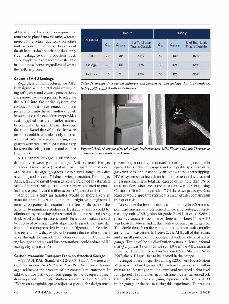
differently between gas and non-gas AHU systems. For gas furnaces, it is estimated (based on visual inspection) that about 80% of AHU leakage (Q 25) was due to panel leakage, 15% due to cooling coil box and 5% due to wire penetration. For non-gas AHUs, failure to install O-ring gaskets represented an estimated 50% of cabinet leakage. The other 50% was related to panel leakage, especially at the filter access (Figures 3 and 4).
Achieving a tight air handler would be more likely if manufacturers deliver units that are airtight with engineered penetration points that require little effort on the part of the installer to maintain airtightness. Leakage at seams could be eliminated by requiring tighter panel fit tolerances and using thick panel gaskets in access panels. Penetration leakage could be improved by using flexible slip-fit style gaskets built into the cabinet that compress tightly around refrigerant and electrical line penetrations, that would only require the installer to push lines through the gasket. The authors estimate that eliminat-ing leakage at seams and line penetrations could reduce AHU leakage by at least 90%.
Carbon Monoxide Transport From an Attached GarageANSI/ASHRAE Standard 62.2-2007, Ventilation and Ac-
ceptable Indoor Air Quality in Low-Rise Residential Build-ings, addresses the problem of air contaminant transport. It addresses two pathways from garage to the occupied space: doorways and the air-distribution system. Section 6.5 states “When an occupiable space adjoins a garage, the design must
of the AHU in the attic also requires the return to be placed into the attic, whereas more of the return ductwork for other units was inside the house. Location of the air handler does not change the supply side “leakage to out” proportion much since supply ducts are located in the attic in all of these homes regardless of where the AHU is placed.
Causes of AHU LeakageRegardless of manufacturer, the AHU
is designed with a metal cabinet requir-ing refrigerant and electric penetrations, and removable access panels. To integrate the AHU into the entire system, the contractor must make connections and penetrations into the air handler cabinet. In many cases, the manufacturer provides seals supplied that the installer can use to complete the installation. However, the study found that of all the items an installer could have sealed, only an area-weighted 16% were sealed. O-ring style gaskets were rarely installed leaving a gap between the refrigerant line and cabinet (Figure 2).
AHU cabinet leakage is distributed
AH location
Return Supply
Q25 Q25,total% of Total Leak That Is Outside
Q25 Q25,total% of Total Leak That Is Outside
Attic 32 39 82% 62 109 57%
Garage 43 63 68% 88 171 51%
Indoors 15 51 29% 63 120 53%
Table 2: Average duct system tightness and portion of duct leakage that is to outdoors [(Q 25,out /Q 25,total ) × 100] in 20 houses.
Figure 3 (Left): Example of panel leakage in electric heat AHU. Figure 4 (Right): Thermostat control wire penetration leak area.
prevent migration of contaminants to the adjoining occupiable space. Doors between garages and occupiable spaces shall be gasketed or made substantially airtight with weather stripping. HVAC systems that include air handlers or return ducts located in garages shall have total air leakage of no more than 6% of total fan flow when measured at 0.1 in. w.c. (25 Pa), using California Title 24 or equivalent.” Of these two pathways, duct leakage would appear to represent a much greater contaminant transport risk.
To examine the level of risk, carbon monoxide (CO) trans-port experiments were performed in two single-story, concrete masonry unit (CMU), slab-on-grade Florida homes. Table 3 presents characteristics of the two houses. In House 1, the AHU was located outdoors and no ductwork was located in the garage. The single door from the garage to the den was substantially airtight with gasketing. In House 2, the AHU, all of the return, and a small portion of the supply ductwork was located in the garage. Testing of the air-distribution system in House 2 found that Q 25,out was 49 cfm (23 L/s) or 4.9% of the AHU nominal flow rate. Therefore, based on Section 6.5 of Standard 62.2-2007, the AHU qualifies to be located in the garage.
Testing at House 1 began by running a 2003 Ford Focus Station Wagon in the closed garage. CO levels in the garage rose within minutes to 18 parts per million (ppm) and remained at that level for a period of 35 minutes, at which time the car was turned off. Clearly this vehicle was not going to produce lethal levels of CO in the garage or the house during this experiment. To produce

42 ASHRAE Jou rna l ash rae .o rg J a n u a r y 2 0 0 8
HouseNumber of
StoriesYear Built ft2 ACH50 Q25,out
House dP
Return Leak cfm
1 1 1965 1750 6.8 151 – 0.4 137
2 1 1995 1280 4.0 48.6 +0.9 48
Table 3: Test house characteristics.
elevated CO in the garage, a five-year-old four-stroke lawn mower was turned on for a period of 80 minutes. Although operation of a lawnmower in a garage is unlikely, a 1996 NIOSH alert noted frequent acciden-tal CO poisonings from small combustion appliances such as pressure washers, saws and generators in confined spaces.7 Indoor CO concentrations never exceeded 24 ppm while CO levels in the garage rose to 2,300 ppm (Figure 5).
CO levels in the house are a function of the quantity of CO transported and the house infiltration rate. CO transport is a function of CO concentration at the source, pathways from garage to house, and the driving force. The peak CO con-centration of 2,300 ppm in the garage provided the source. Pathways occurred through the wall and doorway between the garage and house, as well as from the garage-to-attic into the house. The driving force (house at – 0.4 Pa) was cre-ated by continuous operation of a 70 cfm bathroom fan. The interface between the garage and the attic is relatively tight. Nev-ertheless, attic CO levels rose to as high as 133 ppm. The ratio of indoor CO to garage CO was approximately 1 to 100.
CO levels were sampled at one point inside the wall separating the garage from the den. With the garage CO level at 400 ppm, the concentration in the wall cavity was found to be 303 ppm. Interestingly, when the door between the den and the central hallway was closed, supply air from the continuously running AHU fan created a positive 2.3 Pa pressure in the den wrt the garage and the CO concentration in the wall cavity dropped to 30 ppm within two minutes. This clearly demonstrates that direction of airflow and driving force are critical elements in CO (or any contaminant) transport.
An approximate characterization of the pathway and estimate of CO transport rate can be made. Based on measured house airtightness, a crude assumption that the leakage of the house envelope is uniformly distributed, the house being at – 0.4 Pa (– 0.0016 in. w.c.) wrt the garage, and the wall common to the house and garage represents 6% of the house surface area, we calculate the infiltration rate from garage to house to be a relatively small 4.3 cfm (2.03 L/s).
Testing at House 2 was performed in much the same manner as at House 1. The same lawn mower was operated in the closed garage for a total of 92 minutes. At the end of 25 minutes, the garage CO level had increased to 1,570 ppm, and with the AHU remaining off, indoor CO had risen to only 3 ppm. At 25 minutes, the AHU was turned on and left running continuously for 68 minutes. Indoor CO levels began to increase immediately upon the activation of the AHU, rising to 300 ppm after 23
minutes of AHU operation (Figure 6). Garage and indoor CO levels peaked at 3,207 ppm and 600 ppm, respectively. NIOSH has a ceiling rate of 200 ppm that should not be exceeded at any time and has established an 8-hour time weighted average (TWA) “recommended exposure limit” of 35 ppm.8 It is of concern that the ratio of indoor CO to garage CO was about 20 times higher in House 2 than in House 1, indicating that AHU leakage and associated duct leakage create serious contaminant transport issues.
Testing found that the return leak fraction for the House 2 system was 6.9%, or 48 cfm (22.7 L/s), based on a tracer gas methodology.9 So, the question arises; what level of duct system tightness would be necessary to make House 2 safe from CO poisoning risk? If we select 35 ppm as a maximum permissible level, then the leakage that could be permitted would have to be on the order of 20 times less than what currently exists in that house. The return leak fraction, which is currently 6.9%, would need to be reduced to about 0.35%. In practical terms, this is an unachievable level of airtightness. The authors conclude that AHUs should not be located in the garage.
ConclusionsAHUs are substantially leaky. On average, the return leak-
age in the cabinet alone in 69 homes was found to be 50.6 cfm (23.9 L/s) (actual as-operated leakage), which is 4.2% of the total system measured airflow rate. This level of leakage rep-
Figure 5: House 1 CO in house and garage shown with house pressure wrt garage.
House COGarage CO
Elapsed Time (Minutes)
Gar
age
Car
bon
Mon
oxid
e (p
pm)
Hou
se C
arbo
n M
onox
ide
(ppm
)
48
42
36
30
24
18
12
6
0
2,400
2,100
1,800
1,500
1,200
900
600
300
0200180160140120100200 8040 60 220
Mower On At 0 Minutes Mower Off After 80 Minutes

resents a substantial energy penalty when that air is drawn from an unconditioned space, especially an attic space. A 4.2% return leak from attic air at 120°F (49°C) and 80°F (27°C) dew-point temperature cooled and dehumidified to 75°F (24°C) and 55°F (13°C) dew point temperature causes a 19% increase in energy use. When one considers that locating the AHU in the attic also results in a high proportion of the return leakage from return ducts to also be from the attic, the energy and peak demand implications of the attic location are enormous. The attic is not a good location for AHUs.
Health risks also may result from AHU leakage. As demonstrated by the experi-ments at House 2, the return leakage oc-curring in a tighter than average system, and one that meets the 6% total duct leak-age requirement of Standard 62.2-2007, created a transport mechanism that was more than capable of pro-ducing dangerous levels of CO in the living space. By contrast, the house without the AHU or ductwork in the garage, demonstrated
Figure 6: House 2 CO in house, garage and attic.
little potential for CO poisoning risk, even though the house was operating at negative pressure throughout the experiment. The garage also is not a good location for AHUs.
Garage CO House CO Attic CO
Elapsed Time (Minutes)
Gar
age
Car
bon
Mon
oxid
e (p
pm)
Hou
se a
nd A
ttic
Car
bon
Mon
oxid
e (p
pm)
200180160140120100200 8040 60
Mower On at 0 Minutes
Mower Off After 92 Minutes
AH On After 25 Minutes
3,500
3,000
2,500
2,000
1,500
1,000
500
0
1,400
1,200
1,000
800
600
400
200
0
Advertisement formerly in this space.

46 ASHRAE Jou rna l ash rae .o rg J a n u a r y 2 0 0 8
The best location for AHUs is inside the house, because leakage of air between the conditioned space and the air-distri-bution system causes little to no energy or IAQ consequences. However, two important rules should apply for indoor AHU locations. First, avoid use of building cavities as part of the return system, which can lead to high levels of return leakage from the attic, outdoors, basement, etc. Second, avoid zone depressurization that can lead to moisture (water vapor) intru-sion or combustion safety problems.
A common argument against locating the AHU in the house is that it uses conditioned space. One effective solution is to place the AHU in the garage but carefully isolate it from the the open area of the garage. This can be done by enclosing the AHU in a closet, tightly sealing the walls between the closet and the garage and providing door access to the closet only from indoors or from outdoors. In this design, it is important to allow the closet to be partially vented back to the conditioned space, so that if there is return leakage in the closet, it will draw air primarily from the occupied space.
References1. Cummings, J.B. and J.J. Tooley. 1989. “Infiltration and pressure
differences induced by forced air systems in Florida residences.” ASHRAE Transactions 95:551 – 560 (Figure 3).
2. Henderson, H.I., et al. 2007. “Mitigating the Impacts of Uncon-
trolled Air Flow on Indoor Environmental Quality and Energy Demand in Non-Residential Buildings.” Final Report DOE Project No. DE-FC-36-02GO12012. www.cdhenergy.com/reports/UAF_Final_Report_complete.pdf.
3. Canadian Mortgage Housing Corporation. 1988. Chimney Safety Users’ Manual: Procedures for Determining the Safety of Resi-dential Chimneys.
4. Cummings, J.B., et al. 2003. “Air Handler Leakage: Field Testing Re-sults in Residences.” ASHRAE Transactions 109(1):496 – 502.
5. Cummings, J.B., et al. 2002. “Field Testing and Computer Model-ing to Characterize the Energy Impacts of Air Handler Leakage; Final Report.” FSEC-CR-1357-02, Cocoa, Fla.: Florida Solar Energy Center.
6. ANSI/ASHRAE Standard 152-2004, Method of Test for Determin-ing the Design and Seasonal Efficiencies of Residential Thermal Distribution Systems.
7. National Institute for Occupational Safety and Health. 1996. “Preventing Carbon Monoxide Poisoning from Small Gasoline-Powered Engines and Tools. NIOSH ALERT: 1996.” Atlanta: Department of Health and Human Services (NIOSH) Publication No. 96-118.
8. National Institute for Occupational Safety and Health. 2005. “NIOSH Publication No. 2005-149: NIOSH Pocket Guide to Chemical Hazards.” Atlanta: Department of Health and Human Services, Centers for Disease Control & Prevention.
9. Cummings, J.B. 1989. “Tracer gas as a practical field diagnostic tool for assessing duct system leaks.” Proceedings of 6th Annual Symposium on Improving Building Systems in Hot and Humid Climates.
Advertisement formerly in this space. Advertisement formerly in this space.