The Aircraft Reactor Experiment-Design and...
19
NUCLEAR SCIENCE AND ENGINEERING: 2, 804-825 (1957) The Aircraft Reactor Experiment-Design and Construction 1 E.S. BETTIS, R.W. SCHROEDER, G.A. CRISTY, H.W. SAVAGE, R.G. AFFEL, AND L.F. HEMPHILL Oak Ridge National Laboratory 2 , P.O. Box X, Oak Ridge, Tennessee Received June 18, 1957 The Aircraft Reactor Experiment was designed for operation at temperatures in the region of 1500ºF (1100 K) at a power of 1-3 MWt with a fluoride-salt fuel circulating in a heterogeneous core. The moderator was hot-pressed BeO blocks cooled by circulating sodium. The heat produced was dissipated in water through hot liquid-to-helium-to-water heat exchange systems. All sodium and fuel circuit components were made of Inconel fabricated by inert-gas (Heliarc) welding. The system was heated to design temperature by means of electrical heating units applied over all parts of the system. Instrumentation and control of the experiment were fairly conventional. For the most part, standard instruments were modified slightly for the high- temperature application. The reactor system was constructed and operated in a building specifically provided for the purpose. The Aircraft Reactor Experiment (ARE) to be described in this paper was originally conceived in a very different form from that in which it was ultimately constructed. In fact, the original high-temperature reactor design did not employ a fluoride-salt fuel, and, in order to understand some of the features incorporated in the ARE, a certain amount of historical background is necessary. By 1950, at various places in the country, work had progressed on the handling of high- temperature sodium metal to the point that it was being seriously considered as a coolant for nuclear reactors. Accordingly, a group of engineers and physicists at ORNL started design work on a solid-fuel-pin sodium-cooled reactor, with the fuel consisting of 235 U (as UO 2 ) canned in stainless steel. It was decided to make this a thermal reactor and to use BeO blocks as the moderator. The circulating sodium was to extract heat from the fuel pins and at the same time to remove heat from the moderator blocks. The design of this solid-fuel-pin, BeO-moderated, sodium-cooled reactor proceeded to the point of purchase of the BeO moderator blocks. These blocks, as fabricated for the original reactor design, are shown in Figure 1. The solid-fuel-pin thermal reactor design was found to possess a serious difficulty when the design concept was projected to cover a relatively high-power reactor. The problem was the positive temperature coefficient of reactivity associated with the cross section of xenon at elevated temperatures. This xenon instability was considered to be serious enough to warrant abandoning the solid-fuel design concept, because of the exacting requirement placed on any automatic control system by this instability. An obvious way to avoid the control problem would be to incorporate a liquid fuel that would have a large density change for a given change in temperature. If, upon heating and expanding, a portion of the fuel could, in effect, be made to leave the critical lattice, a self- stabilizing reactor would result. 1 Presented by Mr. Cristy at the American Nuclear Society Meeting in Pittsburg June 10, 1957. 2 Operated by the Union Carbide Nuclear Company for the US Atomic Energy Commission.
-
Upload
truongtuyen -
Category
Documents
-
view
215 -
download
2
Transcript of The Aircraft Reactor Experiment-Design and...
NUCLEAR SCIENCE AND ENGINEERING: 2, 804-825 (1957)
The Aircraft Reactor Experiment-Design and Construction1
E.S. BETTIS, R.W. SCHROEDER, G.A. CRISTY, H.W. SAVAGE, R.G. AFFEL, AND L.F. HEMPHILL
Oak Ridge National Laboratory2, P.O. Box X, Oak Ridge, Tennessee Received June 18, 1957
The Aircraft Reactor Experiment was designed for operation at temperatures in the region of 1500ºF (1100 K) at a power of 1-3 MWt with a fluoride-salt fuel circulating in a heterogeneous core. The moderator was hot-pressed BeO blocks cooled by circulating sodium. The heat produced was dissipated in water through hot liquid-to-helium-to-water heat exchange systems. All sodium and fuel circuit components were made of Inconel fabricated by inert-gas (Heliarc) welding. The system was heated to design temperature by means of electrical heating units applied over all parts of the system. Instrumentation and control of the experiment were fairly conventional. For the most part, standard instruments were modified slightly for the high-temperature application. The reactor system was constructed and operated in a building specifically provided for the purpose.
The Aircraft Reactor Experiment (ARE) to be described in this paper was originally
conceived in a very different form from that in which it was ultimately constructed. In fact, the original high-temperature reactor design did not employ a fluoride-salt fuel, and, in order to understand some of the features incorporated in the ARE, a certain amount of historical background is necessary.
By 1950, at various places in the country, work had progressed on the handling of high-temperature sodium metal to the point that it was being seriously considered as a coolant for nuclear reactors. Accordingly, a group of engineers and physicists at ORNL started design work on a solid-fuel-pin sodium-cooled reactor, with the fuel consisting of 235U (as UO2) canned in stainless steel. It was decided to make this a thermal reactor and to use BeO blocks as the moderator. The circulating sodium was to extract heat from the fuel pins and at the same time to remove heat from the moderator blocks. The design of this solid-fuel-pin, BeO-moderated, sodium-cooled reactor proceeded to the point of purchase of the BeO moderator blocks. These blocks, as fabricated for the original reactor design, are shown in Figure 1.
The solid-fuel-pin thermal reactor design was found to possess a serious difficulty when the design concept was projected to cover a relatively high-power reactor. The problem was the positive temperature coefficient of reactivity associated with the cross section of xenon at elevated temperatures. This xenon instability was considered to be serious enough to warrant abandoning the solid-fuel design concept, because of the exacting requirement placed on any automatic control system by this instability.
An obvious way to avoid the control problem would be to incorporate a liquid fuel that would have a large density change for a given change in temperature. If, upon heating and expanding, a portion of the fuel could, in effect, be made to leave the critical lattice, a self-stabilizing reactor would result.
1 Presented by Mr. Cristy at the American Nuclear Society Meeting in Pittsburg June 10, 1957. 2 Operated by the Union Carbide Nuclear Company for the US Atomic Energy Commission.

A considerable amount of work had been done on molten fluoride salts for use in preparing fuels in liquid form.3 The fluorides did not moderate sufficiently well, however, to make a small thermal homogeneous reactor with fluoride fuel (1). Since the liquid fuel carrier to be used as a substitute for the solid fuel pins would not be required to be a moderator, it was decided to see what could be done to incorporate the fluoride salts in the reactor under study. The fluoride salts were attractive because their very low vapor pressures would permit reactor operation at temperatures around 1500ºF (1100 K) at nominal system pressures.
The first design incorporated stagnant fluoride-salt fuel, and it consisted of a cylindrical moderator matrix, made up of the original beryllium oxide blocks, with vertical holes into which small tubes of the fluoride fuel would be placed. The moderator and fuel tubing assembly would be contained in a cylindrical pressure shell through which sodium would be pumped for cooling the reactor. A number of poison rods would be inserted within the matrix for control and shim
3 By ORNL Materials Chemistry and Metallurgy Divisions.
FIGURE 1: Stacked BeO Moderator Blocks.

FIGURE 2: Schematic Drawing of Circulating-Fuel Reactor System.
purposes. At the top of the lattice, a slab of boron carbide would be placed, and the tops of the fuel tubes would extend through this boron carbide "neutron curtain." The fuel tubes would not be completely filled with liquid at design temperature and zero power, but the fuel level would be above the boron carbide. Any expansion of the fuel occasioned by a rise in temperature would expand more of the fuel to above the boron curtain to achieve fast inherent control or stabilization of the reactor. This system of control effectively circumvented the solid-fuel control problem.
A considerable amount of effort went into the design of this reactor, but in a relatively short time the design was further modified because of some very difficult problems associated with the stagnant liquid fuel. The primary difficulty, which necessitated a change in design, was the prohibitively large radial thermal gradient within the molten fuel. Physical properties measurements of the viscosity and thermal conductivity of the fuel indicated that, for reasonable tube sizes, of the order of 0.080” (2.0 mm) inner-diameter, the center temperature of the fuel would be several hundred degrees F above the wall temperature. In fact, in order to obtain reasonable high-power outputs at reasonable coolant flows the center fuel temperature would be dangerously near the boiling point of the fuel.
Another but entirely different problem associated with the stagnant-liquid-fuel reactor was that difficulties would have arisen in loading the reactor at room temperature and having to achieve criticality after it had been brought to the high design-point temperature. Such an operation would have required large poison rods, and the heat cycling and draining of the coolant between each fuel addition would have constituted an extremely laborious and hazardous routine. Further, in heating from room temperature to operating temperature, the fuel would change from a solid to a liquid, and, since the fluoride salts expand substantially in undergoing this phase change, under certain circumstances a rupture of the fuel tube cold result. The fuel loading problem would recur, of course, when it became necessary to add fuel for burnup and poison compensation in a power reactor after long-time operation.
A solution to the thermal-gradient problem appeared to be circulation of the fuel with turbulent flow to a heat exchanger so that the thermal conductivity of the fuel would not be relied upon as the mechanism for removing heat from the fuel. Also access would be provided so that the fuel loading could be done without disturbing the pressure shell. The only really new problem was that of circulating the high-temperature fuel. Accordingly, the stagnant-fuel design concept was abandoned, and work was begun on the design of a high-temperature circulating-fuel reactor.

The ARE, as finally constructed, comprised the system indicated schematically in Figure 2. The molten fuel was pumped through the 66 passages of the core, through finned-tube heat exchangers, and back to the core in a closed loop. In the heat exchangers, helium extracted heat from the fuel, and the helium, in turn, was cooled by forced circulation over a finned-tube heat exchanger in which water was circulated. Heat generated within the BeO moderator and reflector was transferred to molten sodium that was pumped through the interstices of the moderator and the coolant passages of the reflector. The sodium, in turn, was cooled in a heat exchange system analogous to that used for the fuel circuit.
OPERATING FACILITY
The ARE building was a steel-framework transite-sided mill-type structure. Offices and the control room were located in a single-story portion of the building, underneath which was a basement area that was used for auxiliary heating and cooling facilities, instrumentation, and an emergency power source in the form of a bank of storage batteries. The reactor and its associated equipment were installed in the crane-bay area of the building. This area was divided into three concrete pits that extended to about 6 ft (2 m) below the basement floor level. The pits were designed so that a thickness of 7.5 ft (2.3 m) of concrete, in the form of blocks, could be placed over them to form a complete biological shield for radiation protection. All radioactive portions of the experiment were installed within the three pits, as shown schematically in Figures 3, 4, and 5.
The reactor pit was originally designed to contain only the solid-fuel reactor and to provide for covering it with borated water for disassembly. During operation it would also have served to isolate the high-energy neutron and gamma radiation and thus minimize radiation damage to other equipment, such as the pump-lubrication systems. When adapted to the circulating-fuel reactor the only items in the reactor pit were the reactor, a series of nuclear sensory instruments, and two space coolers for removing the heat lost into the pit through the thermal insulation which surrounded the reactor vessel and piping.
THE REACTOR
An elevation drawing of the reactor and the surrounding gas plenum chamber and thermal insulation is shown in Figure 6, and the dimensions and volumes of the reactor vessel and its contents at a mean temperature of 1300ºF (980 K) are given in Table 1. The pressure shell was composed of a 2-inch-thick (5 cm) Inconel sheet fabricated into a cylindrical shape with a longitudinal Heliarc weld and with heads welded on by the Heliarc welding technique.4 The pressure shell was designed to ensure that thermal stress would not exceed 3000 psi (20 MPa). This required that the flat heads be reinforced to 4 in. (10 cm) at locations where they were weakened by tube penetrations.
A plate of 1-inch-thick (2.5 cm) Inconel was spaced off the bottom of the pressure vessel by eight 1-inch-diam (2.5 cm) studs which were fastened into the plate and rested unattached on the inside bottom of the pressure shell. This plate had slots cut in it to allow the reverse bends of the fuel tubes to protrude through it. There were also round holes to allow for passage of the fission chamber and control rod thimble tubes through the pressure shell. The BeO-moderator blocks 4 The welding procedures used were the result of thousands of hours of developmental work by the ORNL Metallurgy Division.

FIGURE 3: Isometric Drawing of Reactor in Pit.

FIGURE 4: Isometric Drawing of Fuel System.

FIGURE 5: Isometric Drawing of Sodium System.
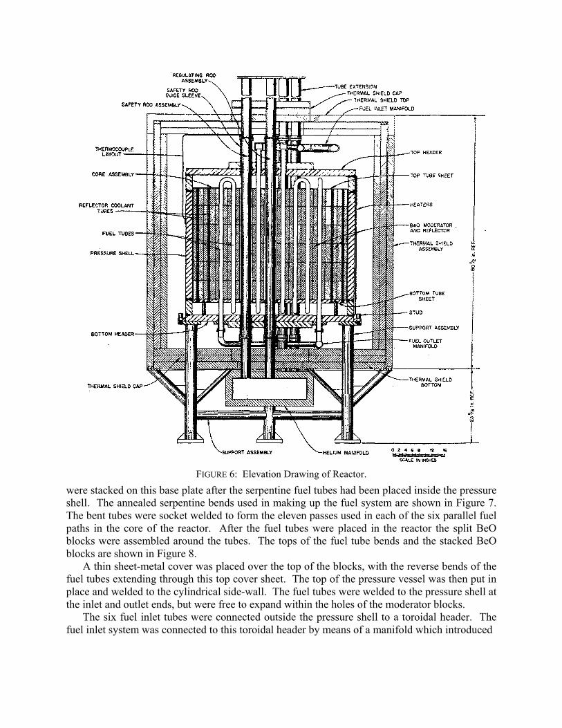
FIGURE 6: Elevation Drawing of Reactor.
were stacked on this base plate after the serpentine fuel tubes had been placed inside the pressure shell. The annealed serpentine bends used in making up the fuel system are shown in Figure 7. The bent tubes were socket welded to form the eleven passes used in each of the six parallel fuel paths in the core of the reactor. After the fuel tubes were placed in the reactor the split BeO blocks were assembled around the tubes. The tops of the fuel tube bends and the stacked BeO blocks are shown in Figure 8.
A thin sheet-metal cover was placed over the top of the blocks, with the reverse bends of the fuel tubes extending through this top cover sheet. The top of the pressure vessel was then put in place and welded to the cylindrical side-wall. The fuel tubes were welded to the pressure shell at the inlet and outlet ends, but were free to expand within the holes of the moderator blocks.
The six fuel inlet tubes were connected outside the pressure shell to a toroidal header. The fuel inlet system was connected to this toroidal header by means of a manifold which introduced

fuel at two points on the inlet distribution header. The reactor constituted an anchor point for the fuel and sodium piping of the system. Other anchor points were the pumps and heat exchangers for the two systems. All piping stress was calculated as accurately as possible, and the piping was installed in a pre-stressed condition so as to be unstressed at design temperature.
There were six sleeves which ran entirely through the reactor from top to bottom. These sleeves were open at each end to permit circulation of helium coolant and to prevent a possible collection of fuel inside the sleeves in the event of a rupture in the fuel system. The two sleeves which ran through the reflector region of the core served as locations for fission chambers which were inserted into them from the top. The other four sleeves accommodated the three shim rods and the central regulating rod.
The gas-tight can which enclosed the rod drives and fission chamber drives, which were immediately above the reactor tank and outside the top shielding plugs, is shown in Figure 3. The flexible bellows used to accommodate thermal expansion of the sleeves that penetrated the reactor and comprised the rod and fission chamber gas cooling systems may also be seen in Figure 3.
DESIGN CONSIDERATIONS
Detailed analyses of the requirements of the fuel-circulation system and fuel inventory considerations indicated the use of more fuel tubes in the reactor, but the necessity for using the existing BeO blocks required a design which used not more than 66 fuel tubes. Since the power level of this reactor was to be in the 1-3 MWt range and since it was desirable to simulate the temperature pattern of a high-power reactor, the fuel circulation rate was determined by the temperature gradient to be obtained. Analyses of the thermal patterns that would exist in a single fuel tube indicated that unless the fuel flowed turbulently, the wall temperature would become dangerously high (2). This was a direct result of the low thermal conductivity of the fuel. Therefore, to be sure that the Reynolds modulus was always kept above the transition region (classically 2000 to 10,000), it was evident that the fuel would have to make several passes through the reactor in series. A study of the pressure drop and Reynolds number characteristics of various series methods was therefore made which indicated that the minimum flow requirements could be met without excessive pressure drop by providing six parallel systems of 11 tubes each. This arrangement provided for a minimum Reynolds modulus of 14,000 and gave a measure of safety against slight inequalities of flow between parallel passages. Experimental results from a full-scale water and glass model indicated that full turbulence would be maintained within the reactor core with flow which produced a Reynolds modulus of 5000.
TABLE I DIMENSIONS AND VOLUMES AT A MEAN
TEMPERATURE OF 1300ºF (980 K)
Core height Core diameter Side reflector height Side reflector inside diameter Side reflector outside diameter Top reflector thickness Top reflector diameter Bottom reflector thickness Bottom reflector diameter Pressure shell inside diameter Pressure shell wall thickness Pressure shell inside height Pressure shell head thickness Fuel tube diameter (OD) Fuel tube wall thickness Reactor vessel volume BeO in core BeO in reflector Fuel volume in core Sodium volume in core Inconel within the pressure shell Volume of control thimbles
90.93 cm 84.60 cm 90.93 cm 84.60 cm 122.0 cm 10.8 cm 84.60 cm 12.6 cm 84.60 cm 123.3 cm 5.13 cm 114.3 cm 10.3 cm 3.137 cm 1.5 mm 1.32 m3 0.412 m3 0.500 m3 0.0504 m3 0.280 m3 0.049 m3 0.027 m3

FIGURE 7: Bent tubes ready for installation in reactor vessel.
A very serious defect in this design was that the fuel system of the reactor was non-drainable. In view of the fact that the moderator blocks would allow no other fuel configuration, it was decided to accept the problems associated with a non-drainable fuel system. This resulted in the employment of rather drastic safety features in the system, and the operation of the reactor was accomplished by exercising extreme care in every phase. The non-drainable feature prohibited the repair of a known gas leak and made necessary the use of awkward methods for disposing of fission fragment escape from this leak when power operation of the system was attained.
Since the ARE was deigned to operate in the range between 1000-1500ºF (810-1100 K), means had to be provided for supplying heat to the system prior to the generation of heat within the system by the fission process. The melting point of the fluoride carrier used as a vehicle for the uranium fuel was near 950ºF (780 K), and it was therefore necessary to be able to heat the system to a temperature of at least 950ºF. Also, some heat had to be applied at the pressure shell so that the reactor could be brought to a temperature well above the melting point of sodium. In order to provide the required heating, 48 Inconel-clad strip heaters of 1500-W capacity each were clamped around the cylindrical wall of the pressure shell in a vertical arrangement, as shown in Figure 9. The maximum power input to these heaters was about 45 kW.

FIGURE 8: Reactor Core (top view).
In order to ensure an even distribution of temperature along the fuel-distribution lines, these lines, as well as all major components of the system, were double-walled to provide an annular gas space in which helium was circulated. Electric resistance heaters were placed on the outer surfaces of the double walls. The flowing gas in the annular space was also a precaution against a freezeup which might result if a heater should burn out on any portion of the fuel circuit.
Shim rods, which consisted of segmented boron carbide slugs canned in stainless steel and mounted on a small stainless steel rod, were used for shim control and safety of the reactor. Enough poison had to be included in these rods to provide for running the reactor subcritical at room temperature, since the system was non-drainable. Such a precaution was also essential to ensure ability to disassemble the reactor in the event it was impossible to flush the fuel out of the core at the end of the experiment. The shim rods were in the shape of cylinders 1 inch long with ¼ inch wall thickness. A hole in the center provided space for the mounting rod with sufficient clearance for gas cooling to prevent overheating when the reactor was operating at power.
CONTROL SYSTEM
As stated above, the drives for the shim rods were located in the gas-tight housing directly above the reactor (Figure 3). A reversible AC motor drove a lead screw for each shim rod. An electromagnet was moved up and down by this lead screw in a piston-type housing. The armature of the electromagnet was fastened to the long stainless steel rod to which was attached the shim rod hanging in the reactor. When the electromagnet was de-energized the rods fell into

FIGURE 9: Reactor vessel during installation of strip heaters.
the reactor. During the last 6 in. of its travel, the armature compressed gas in the cylinder and thereby formed a pneumatic shock absorber for the rod.
The rods were made up of short segments in order to provide flexibility, so that even if the shim rod thimble became distorted in the lattice the rod would conform and fall into place. At the very center of the reactor, a 1-in.-diam stainless steel rod mesas inserted in the control rod thimble hole for vernier control of the reactor. This rod was driven by an on-off type of

reversible servomotor, which could be actuated manually from the control console or could be actuated by a signal from the micro-micro-ammeter.
In the pit with the reactor there was a lead-shielded slab which contained five horizontal instrument tubes (see Figure 3). There were two boron-coated ionization chambers, a BF3-filled proportional counter chamber, a log N compensated ionization chamber, and a chamber for operating the micro-micro-ammeter which, in turn, operated the servo control. These neutron sensors could be moved in and out of the shielded housings to provide control signals as the level of activity of the reactor was changed.
HEAT EXCHANGE SYSTEMS
The fission generated heat from the reactor was removed by pumping the hot fuel through a finned-tube heat exchanger where the heat was picked up by helium, which, in turn, was circulated by means of a large centrifugal blower in a closed loop. Inside the helium duct was a finned-tube heat exchanger through which plant water flowed from the water main to a sewer. Actually the fuel heat exchanger and the water heat exchanger were each divided into two units with the liquid sides being connected in parallel. One fuel heat exchanger was mounted adjacent to a water heat exchanger with a 4-in. space between. This space accommodated a vertically-operating heat barrier door which could be lowered by means of an actuator motor to reduce heat loss while bringing the system to temperature or raised into a covered recess for power operation of the system. The other pair of heat exchangers was located in a similar manner, and the pairs were connected by a sheet steel duct that enclosed the helium blower.
The fuel heat exchangers consisted of 1-in.-o.d. Inconel tubing with spiral stainless steel fins 2 in. in diameter on the outside. The tubes were not finned at the bends so that each 27-ft length of tubing could be bent into nine passes approximately 3 ft long. Six of these tubes were welded into headers at each end, and the headers were baffled so that the flow was through three pipes in parallel. The fluid traveled a total distance of approximately 54 ft while in the heat exchanger.
At a flow rate of 20 gpm through each heat exchanger, the pressure drop was 22 psi. For a fuel inlet temperature of 1522°F (1100 K) and an outlet temperature of 1209°F (927 K), the helium gas temperatures at a flow rate of 12,300 cfm (5.80 m3/s) (hot) were 180°F (355 K) at the inlet and 620°F (600 K) at the outlet. In the water heat exchanger, which cooled the helium, the water temperature increased from 70 to 135°F (295 - 330 K).
An operating fuel pump, together with a standby fuel pump, was mounted above the heat exchanger assembly. These pumps were sump-type centrifugal pumps with gas seals and overhung bearings. The sump tank served a dual capacity as an expansion tank for the fuel. A helium pressure of 5 psi was maintained over the fuel in the sump tank. The standby pump was isolated from the fuel system by a frangible disk valve on both the inlet and discharge lines of the pump. Two more air-actuated bellows-seal valves were used to isolate the fuel system from the fill tanks. The layout of the fuel system is shown schematically in Figure 4, which does not show the water heat exchangers or the duct work enclosing the helium circuit.
The smallest pipes in the fuel system were the 1-in.-diam inlet and outlet lines to the heat exchangers. As may be seen in Figure 4, these lines had two or more right-angle bends in them to provide for thermal expansion, since both the pumps and the heat exchangers were solidly anchored. Line 115 had the highest stress of any in the fuel piping. It was prestressed cold to 38,000 psi and the computed hot stress was 19,600 psi. The main fuel lines from and into the reactor were 2-in.-diam lines.

The entire piping system of both the fuel and sodium circuits vas enclosed by stainless steel tubing which formed an annulus spaced 1 in. from the outside wall of the primary pipe. Through this annulus helium was circulated by means of two positive-displacement pumps. This gas system communicated with and became a part of the rod cooling system for the reactor. As stated above, it also served to equalize any thermal differences created along the lines by too much or too little heat input from the electrical heating. In addition, copper gauze placed at sample points in this gas stream was removed for periodic tests in a phenolphthalein solution in order to monitor sodium or fuel leaks in the primary circuits. Temperature monitoring was obtained with Chromel-Alumel thermocouples that were welded to the outside of all fuel and sodium lines at a minimum of 3-ft intervals. These thermocouples were connected to recording or indicating instruments.
The sodium cooling circuit is shown schematically in Figure 5. In this system, two independent circuits were operated. This duality was, in the interest of safety, an effort to ensure some cooling of the system in the event of a single pump failure. Even if the fuel pump failed, sufficient heat transfer was available to remove the after-heat from the reactor by means of the sodium circuit, since the sodium was in contact with the fuel tubes.
The sodium and fuel lines, as stated above, were heated electrically with heaters in the form of ceramic half-cylinders that were installed around the annular piping. Over the heater units was a 4-in.-thick layer of thermal insulation. Thus a 2-in.-diam line with the annulus, heater, and insulation attained a diameter of about 14 in.
The heat exchanger pits included, in addition to the fuel loop, the sodium loop, the rod cooling and monitor-annulus blowers, and equipment for handling radioactive off-gases. This off-gas system, which consisted of compressors, holdup tanks, sodium filters, and a considerable array of gas lines and valves, was never used because of a leak in the gas closure of the fuel pump. When the fission gases were found to have leaked into the pits, which were not completely gastight, it became necessary to extemporize a gas pumping system by using compressed air jet pumps to pull a slightly negative pressure (6-10 in. H2O) on the pits and to discharge the gas through a temporary 2-in. pipeline some 1000 ft away from the building.
FILL AND DUMP TANKS
The diagrams of the fuel and sodium systems, presented above (Figures 4 and 5) show the general arrangement of the sodium flush-and-fill tanks, the fuel fill tanks, and the hot-fuel dump tank in the dump-tank pit. Three Inconel tanks of 14.5-ft3 capacity were used to contain the sodium prior to filling and subsequent to dumping from the circuit. These tanks communicated with the basement area through the pit wall by heated lines so that the hot sodium could be pumped into the vented tanks when the system was nearing the operational phase. Two similar tanks provided for the storage of the fluoride carrier prior to operation of the system.
All these tanks were suspended, slightly above the floor, on rods anchored in steel beams near the top of the dump-tank pit. This suspension permitted the tanks to move in any direction in the horizontal plane as the piping systems connected to them expanded upon being heated. All the tanks were covered with Calrod electric heating units and then insulated with 4 in. of thermal insulation.
The other tank located in the pit was the hot-fuel dump tank, which was of different design. It was installed to collect the fuel after the experiment had been run. The intense radioactivity of the fuel after having been used for operation at a power level of 2 MW for appreciable periods of

time produced sufficient heat to make cooling mandatory, and if the fuel were to be maintained molten after the radioactivity had decayed it was also necessary to supply heat to the tank. Accordingly, this hot-fuel dump tank was designed for cooling of the fuel by gas convection and for shutting off the circulation of gas and adding heat when desired.
The hot-fuel dump tank was constructed like a small fire-tube boiler. The cylindrical tank had an inside diameter of 40 in. and was 36 in. high. Running through the tank from top to bottom were 91 sched-40 2-in.-diam pipes, or flues, for gas cooling. The tank had a capacity of approximately 19 ft3, and therefore could hold more than two volumes of the fuel circuit. Mounted above the tank was a sheet-metal chimney to accentuate the flow of pit gases through the coolant flues in order to prevent overheating of the fuel. The 91 flues were disposed symmetrically in the dump tank so that the maximum distance through which heat had to flow before contacting a coolant tube wall was about 2 in. A damper was located in the top of the chimney or stack so that the flow of gas could be essentially stopped when it became necessary to add heat for maintaining the fuel in the molten condition.
All the dump tanks were equipped with heated gas-vent lines in which were located pneumatically operated valves. Helium pressurizing lines also ran to each tank, and these lines were controlled by pneumatically or solenoid operated valves. All tanks contained dip lines so that the liquid could be transferred from the tanks to the system by pressurizing the tank with helium. Specially designed and fabricated high-temperature valves were installed in the liquid line to each tank.
Pre-installation tests of valves of the type to be used in the ARE indicated that some valves were leaktight while others were not. Unfortunately no way of improving the valves was evident and time did not permit a new valve development program. Since it was also impractical to check at high temperatures every valve intended for use in the system, a decision was made to use the valves as received and, in case they leaked, to pressurize the fill tanks with inert gas and thereby operate the systems with an overriding back pressure below the valve. All the liquid line valves were spring-loaded in one direction with pneumatic actuators working against the spring. In every case the spring was used for the “safe” operating direction of the valve.
All pneumatic instruments were operated with dry helium, since the instrument gas bleeds might be radioactive. Also an effort was made to enrich the pit atmosphere with helium as much as possible in order to minimize the chance of fire in the event of a sodium leak. Further, the closed helium loops on the fuel and sodium heat exchange system were not completely gastight. The helium consumption rate for the experiment was therefore phenomenally high, but since the experiment was of very short duration this extravagant helium usage was acceptable. The helium for the experiment was furnished from tank trailers which were filled from railroad tank cars. All the helium was passed through a NaK scrubber to remove traces of oxygen and water vapor.
THE CONTROL ROOM
Control of the ARE, from the very beginning, was considered to be an integral part of the design. In fact, control engineers were active in the original planning of the system. The instrumentation and control of the experiment became quite involved and, in many cases, somewhat awkward, but the question of whether or not the system was adequately under control never was considered to be in doubt.

The parameters with which control was primarily concerned were neutron flux, or fission rate, and temperature. Secondarily, such important quantities as liquid level, liquid flow, pressure, and pump speed had to be measured and controlled as accurately as possible.
The mean reactor temperature was determined by controlling the amount of uranium added to the system and by the positioning of poison rods within the active lattice of the reactor. The computed critical mass and the preliminary critical experiments associated with the experiment are discussed in the following paper (3), as is the batch method of adding uranium to bring the reactor to criticality (4). A brief description of the control and instrumentation hardware is given here.
The neutrons were measured by two fairly conventional (except for certain high-temperature modifications) fission chambers located in thimbles placed in the reactor reflector. These chambers could be lowered or raised in the core by means of reversible motors, the control of which was effected from the control console by means of switches. Also a BF3 counter and compensated ionization chamber located in shielded thimbles in the reactor pit were used for neutron sensing at higher power levels. Indication of count rate and fission rate level was given by recording instruments mounted directly in front of the console of the instrument board. Synchro indicators on the console showed the positions of the fission chambers and all the control rods. Positioning of the control rods was also effected by reversible motors, which were operated by means of switches on the console. The usual travel-limit lights were mounted on the console, along with the respective control switches and synchro indicators.
The ionization chambers used for fission-rate safety controls were connected to the electronic system which provided energizing current for the magnets which held the shim rods. Also an instrument (the pile period recorder) which produced a signal proportional to the rate of change of the fission rate was incorporated in the safety scram circuit. Thus the reactor was shut down by the dropping of all safety rods if the fission rate became excessive or if the positive rate of change of the fission rate became too large. As may be seen, the nuclear instrumentation and control of the ARE were quite orthodox and no different from those of other reactors in this country.
Operation of the system at temperatures near the upper limit permitted by the structural material made it imperative that temperatures be measured as accurately as possible at all points where hot spots might occur. Therefore recording temperature instruments were used for the more critical points in the system. The recorders for these points were located directly in front of the operating console on the instrument board. Reactor inlet and outlet temperatures and the temperature differences across the reactor were displayed on recorders located adjacent to the nuclear instruments. Temperatures of decreasing importance were displayed at more remote points on the instrument panel. Thermocouples attached to most points along pipe lines of both the fuel and sodium circuits were connected to temperature-indicating instruments located in the basement control area.
The liquid levels in the sumps of the sodium and fuel pumps were indicated by floats and by electrical conductivity probes that extended through the top of the sump tank. Signals from the floats were picked up inductively through inverted Inconel wells above the sump tank tops. The levels had to be controlled to prevent flooding of the pump seals and loss of prime. The free liquid surfaces in the sump tanks constituted the highest points in both the sodium and fuel circuits. Changes in liquid level could be caused by temperature changes in the liquid or by a shutoff valve leaking fluid from the system into a fill tank. In operation no difficulty was

experienced with level changes in the fuel circuit, but leaky valves in the sodium circuit made frequent adjustments necessary.
Pressures in the system were measured by differential pressure transmitters located at strategic points in the liquid systems. The fluid pressure exerted on a bellows was balanced with a helium pressure by a null-balance principle, and the balancing helium pressure was indicated on pressure gauges located on the instrument panels.
On the various pumps, tachometer generators provided electrical signals which were calibrated in rpm, and these were indicated on the instrument panels. Acoustical vibration pickup units were mounted on all rotating elements. Signals from these units were amplified and converted into sound which was audible from a speaker in the control room and provided a qualitative check of pump operation. A switch allowed manual selection of any one of these signals for monitoring.
The speed of each pump was calibrated against flow when pumping water during the shakedown runs. The sodium circuit also had electromagnetic flowmeters which produced an electrical signal calibrated in gpm of sodium flow. The flow in the fuel system was measured by a specially designed high-temperature rotameter which used the same type of induction sensing as that used in the liquid level devices for the pump tanks.
In general, the process instrumentation of the ARE was adequate, but there were numerous weak points in the system. The main problem lay in adapting existing sensors to high-temperature application. Very real advances have been made in instrumentation development since completion of the ARE, and instruments now available are far superior to those used in this experiment.
AUXILIARY EQUIPMENT
The basement area was used primarily for the distribution and control of the electrical-heating equipment provided for bringing the experimental system up to the operating temperature. The power for the building was supplied by a three-phase bank of three 250-kVA transformers from a 13.8-kV line and was stepped down to 460 V. The power was fed to two breakers. The 120/208-V service was transformed in the basement of the building from the 460-V lines. A 75-kVA emergency diesel-powered generator set, which produced 120-208 V, was connected so as to pull part of the load in case of a purchased-power failure. Storage batteries were also floated on the DC line for use in case of a line failure. Direct current was supplied by a motor-generator set, which was controlled so as to produce the required current and to keep the batteries charged. A DC-AC generator set produced alternating current for the instruments. The building had an emergency lighting system which ran off of the batteries. With only the instruments, heating, lighting, and compressed air systems operating, the building load was approximately 200 amperes at 460 V.
The largest use of power in the experiment was for process heating, which, as stated above, was required to bring the systems to the temperature required for filling with molten fluorides and with sodium and to make up for heat losses. The various types of heaters used included strip heaters, tubular heaters, flat-molded heaters, semicylindrical molded heaters, wrapped resistance units, and resistant sections. The strip units were used on the low-temperature tanks. The tubular units were used on the pressure shell, high-temperature tanks, off-gas lines, and many of the small lines, as well as some valves and odd-shaped units. Most of the strip and tubular heaters were 230-V units. The semicylindrical molded units were used on the fuel and sodium
lines, valves, and some of the small tanks. The flat molded units were used on the pumps, some of the tanks, and the elbows of some of the pipes. The wrapped resistance units were used on some of the small lines which were to run at low temperature with a low power demand. The resistant heating sections were used on special pipes that required high heat for short periods of time or that could not be reached by the other types of heaters. The molded units were 120 V, with half-units of 60 V. The wrapped resistance units were cut for 230-V service.
All the heating units were mounted as close as possible to the unit to be heated. For example, straps or bands were placed around tanks and the heaters were bound into place to produce the best possible conditions for heat transfer. In most cases, metal sheets were placed around the heaters to separate the insulation from the heaters. Stainless steel wire was welded to the terminals of the heating units, and beads were placed on the wires to reach through the insulation where they were in turn welded to copper wires with heat-resistant insulation. These installation procedures were carried out for all types of heaters used. In most cases, the heating units were connected, three units in a series, to a leg. In the case of a closed delta, there were three units in each leg or a total of nine units. The open delta had six units.
The maximum voltage that could be applied to a single 120-V unit was 115 V and, to a single 230-V unit, 208 V. On the closed or open delta units of the 230-V class, which had three units in series, each leg was rated 690 V, but the maximum applied was 600 V. On the units of the 120-V class, which were rated 360 V, the maximum applied was 300 V. These limits of voltage provided a safety factor against burnouts. During the final run burnouts occurred on only three deltas.
The power to the heating units was controlled either by Powerstats or voltage regulators. There were five automatic controls used in the system, and these were backed up by Powerstats in order to provide control over the longest heating range possible.
In addition to the electrical distribution and control system, the basement contained the water distribution system which provided the entire heat sink for the experiment. From the basement area the water flow to all portions of the heat disposal system could be measured and controlled. Since the expected life of the experiment was only of the order of 100 hr, no effort was made to conserve water. The water distribution system was designed to ensure adequate cooling at all times. A vertical cylindrical tank served as a reserve supply in case of temporary loss of water from the main. This tank was of sufficient size to permit operation of the facility for approximately 1 hr in the event of a water main failure.
SUMMARY OF CONSTRUCTION EXPERIENCE
By far the most crucial part of the construction of the ARE was the welding. The entire system was made of Inconel, and all joints and closures were effected by Heliarc welding to assure high-quality welds. The helium used during the welding was required to have a dew point of -40ºF. Joint preparation prior to welding was meticulously controlled, and weld setups were inspected before the welders were allowed to begin the fusion. Dye penetrant, as well as gamma graphing, was used in the inspection of every weld. When there was any detectable defect, the weld was cut out and remade. The integrity of the experimental system can be attributed to the thoroughness of the welding techniques worked out before the construction was started and to the conscientious adherence to these techniques on the part of the installation field forces.
The heating of the equipment in a completely uniform manner also constituted a major problem. The original articulation of the heater control was increased several-fold before it

became satisfactory. It has been found that when all parts of a system containing molten fluorides are heated to well above 1200ºF, no trouble is encountered in handling the melt by inert gas pressure above the liquid surface.
REFERENCES
1. R.C. BRIANT AND ALVIN M. WEINBERG, Nuclear Science and Engineering 2,797 (1957). 2. H.F. POPPENDIEK AND L.D. PALMER, Chem. Eng. Progr. Symposium Ser. 50, No. 11, 93
(1954). 3. W.K. ERGEN, A.D. CALLIHAN, C.B. MILLS, AND DUNLAP SCOTT, Nuclear Science and
Engineering 2, 826 (1957). 4. E.S. BETTIS, W.B. COTTRELL, E.R. MANN, J.L. MEEM, AND G.D. WHITMAN, Nuclear
Science and Engineering 2, 841 (1957).