The Acousto-Ultrasonic Approach - NASA · PDF filecosponsored by NASA and the American Society...
32
NASA Technical Memorandum 89843 The Acousto-Ultrasonic Approach (t_ASA-'Itl-8984 2) 'ILI_ACC U S,IC- UI'II_ASOIIIC cSCL _.t._I_CACll (NASA) 30 P lqD G3/38 N87-20562 uncla_ W5389 Alex Vary Lewis Research Center Cleveland, Ohio Prepared for the Acousto--Ultrasonics: Theory and Application cosponsored by NASA and the American Society for Nondestructive Testing Blacksburg, Virginia, July 12-15, 1987 https://ntrs.nasa.gov/search.jsp?R=19870011129 2018-05-03T07:41:43+00:00Z
Transcript of The Acousto-Ultrasonic Approach - NASA · PDF filecosponsored by NASA and the American Society...

NASA Technical Memorandum 89843
The Acousto-Ultrasonic Approach
(t_ASA-'Itl-8984 2) 'ILI_ AC CU S,IC- UI'II_ASOIIICcSCL
_.t._I_CACll (NASA) 30 P
lqD
G3/38
N87-20562
uncla_W5389
Alex VaryLewis Research Center
Cleveland, Ohio
Prepared for the
Acousto--Ultrasonics: Theory and Application
cosponsored by NASA and the American Society for Nondestructive Testing
Blacksburg, Virginia, July 12-15, 1987
https://ntrs.nasa.gov/search.jsp?R=19870011129 2018-05-03T07:41:43+00:00Z


THE ACOUSTO-ULTRASONIC APPROACH
Alex Vary
National Aeronautics and Space Administration
Lewis Research Center
Cleveland, Ohio 44135
CDLn
!LO
SUMMARY
This paper reviews the nature and underlying rationale of the
acousto-ultrasonic approach, suggests needed advanced signal analysis and
evaluation methods, and discusses application potentials. The term
acousto-ultrasonics denotes an NDE technique that combines some aspects of
acoustic emission methodology with ultrasonic simulation of stress waves. The
acousto-ultrasonic approach uses analysis of simulated stress waves for
detecting and mapping variations of mechanical properties. Unlike most NDE,
acousto-ultrasonics is less concerned with flaw detection than with the
assessment of the collective effects of various flaws and material anomalies.
Acousto-ultrasonics has been applied chiefly to laminated and filament-wound
fiber reinforced composites. It has been used to assess the significant
strength and toughness reducing effects that can be wrought by combinations of
essentially minor flaws and diffuse flaw populations. Acousto-ultrasonics
assesses integrated defect states and the resultant variations in properties
such as tensile, shear, and flexural strengths and fracture resistance. Matrix
cure state, porosity, fiber orientation, fiber volume fraction, fiber-matrix
bonding, and interlaminar bond quality are factors that underliDe
acousto-ultrasonic evaluations.
INTRODUCTION
Conventional NDE. - The main purpose of nondestructive evaluation (NDE) is
to provide a basis for determining whether a structure will perform reliably
when placed in service. This is usually done with conventional flaw detection

techniques and it depends on defining which flaws are harmful. Obviously, it
is unrealistic to discard a part simply because it contains minor flaws or
anomalies that normally arise during fabrication. Certainly, some flaws are
likely to be more harmful than others because of their size, location, and
proximity to each other. But, in some materials (e.g., fiber reinforced
composites) the harmful effects of certain types of flaws cannot always be
dete_ined unambiguously.
Although composites can have broken fibers, delaminations, local porosity,
resin rlch areas, etc., the overall effect may be benign. The combined effect
of these defects is often difficult to assess analytically. More theoretically
valid analysis models are needed to incorporate the complex fracture process
that occur in composites. 1 On the other hand, a composite structure may be
free of readily detectable flaws but still exhibit low strength and be
unsuitable for use. Low composite strength may be due to poor bonding between
plies or between the fibers and matrix.
Mechanical Property Assessment. - The preceding observations suggest a
need for NDE methods that can assess variations in mechanical properties rather
than merely detect minor flaws whose relevance is questionable. These methods
should at least quantify relative strength and fracture resistance by measuring
the combined effect of all deficiencies due to subcritical flaw populations and
microstructural anomalies in a volume of material. Then, fracture analysis and
analytical life prediction methods would be supplemented by NDE approaches that
2verify properties that contribute to structural integrity and reliability.
Acousto-ultrasonics. - The acousto-ultrasonic approach addresses the
above-mentioned requirements. 3 It complements other NDE approaches to
materials characterization 4 and offers advantages that make it the preferred
one to use in some cases. Accordingly, the purpose of this paper is to
2

describe the acousto-ultrasonic approach, its genesis, rationale, signal
analysis methods, and applications.
BACKGROUND
Terminology. - The term acousto-ultrasonics was coined to express the
close relation with acoustic emission. "Acousto-ultrasonics" may be taken as
a contraction of "acoustic emission simulation with ultrasonic sources."
Acousto-ultrasonic waves like acoustic emissions are generally ultrasonic in
nature. The acoustic emission method depends on loading to excite spontaneous
stress waves such as those accompanying plastic deformation and crack growth. 5
Acousto-ultrasonics differs mainly in that the ultrasonic waves are benign and
6are generated externally by a pulsed source (usually a piezotransducer).
Objective. - The objective in acousto-ultrasonics is to simulate stress
waves that resemble acoustic emission waves but without disrupting the
7material. Once launched inside the material sample, the waves are modified
by stochastic processes like those that affect spontaneous acoustic emissions
from internal sources during stressing, deformation, etc. Moreover,
acousto-ultrasonic waves are launched periodically at predetermined times and
with predetermined repetition rates.
In contrast to acoustic emission practice, the idea in acousto-ultrasonics
is to keep the nature and location of the source of ultrasonic radiation known
and fixed. Then, the inverse problem is not concerned with source location
and characterization but with characterization of the material medium between
8the source and receiver.
Alternative Approaches. - Materials characterization can, of course, be
accomplished by other ultrasonic methods, 9 for example, by pulse-echo
ultrasonic measurements of velocity and attenuation. These measurements can
usually be correlated with variations in microstructure (e.g., grain size,
porosity), elastic constants, strength, toughness, etc. Pulse-echo ultrasonics
3

is based on knowing the wave propagation path, avoiding multiple reflections
and overlapping echoes, and by accounting for dispersion and similar effects.
The acousto-ultrasonic approach is among the alternatives that should be
considered for material property characterization. It is specifically designed
for cases where constraints imposed by pulse-echo and similar conventional
ultrasonic approaches are impractical.
METHODOLOGY
Probe Configuration. - In acousto-ultrasonics the sender and receiver
proves are usually coupled to the same side of the test object. (In many
applications only one side will be accessible.) The probes are coupled at
normal incidence to the surface of a test piece. The receiver is displaced by
a fixed distance from the sender. In the limit of zero separation, this
configuration reduces to conventional pulse-echo ultrasonics. The send-receive
transducer pair is moved about as a unit and the test object is scanned to map
material property variations, FiE. I.
Direction Criterion. - The rationale of the acousto-ultrasonic probe
configuration may be understood by considering the materials characterization
problem posed by fiber-reinforced composite laminates. For laminates it is
desirable to measure properties with ultrasonic energy that has propagated
laterally (parallel to the lateral surfaces). Transducers coupled to edges
could send and receive the signals, but although thick laminates may allow
effective coupling to edges, thin laminates pose a problem. (Laminate
thicknesses range from a fraction of a millimeter to several centimeters.) In
large laminated sheets the signal would probably be lost before reaching an
opposite edge because composites are usually highly attenuating.
In laminated composite structures some or all edges may be inaccessible
(e.g., cylinders, vessels, fuselages). Other examples include wood fiber
boards, paper products, ropes and cables, and plate/sheet/strip stock. The
4

need to use energy that has propagated parallel to major surfaces arises
whether the laminates are polymer, metal, or ceramic matrix fiber reinforced
composites.
Echo System. - The acousto-ultrasonic configuration assures that numerious
wave interactions occur in the volume of material interrogated. Instead of
consisting of a series of isolated echoes, as in pulse-echo ultrasonics, the
acousto-ultrasonic signal will be much more complex. In test objects like
laminated panels that have a thickness less than the spacing between probes the
received signal will consist of overlapping echoes, Fig. 2. For objects having
greater thicknesses echoes will tend to separate due to delayed arrivals of
individual echoes. Despite its complexity the acousto-ultrasonic signal can
be readily analyzed to provide information about lateral property variations.
(Signal analysis methodologies are discussed later.)
Transducers. - In current practice piezoelastic probes are coupled
directly to the surface of a test object. An alternative, based on contactless
lasers probes will be discussed later. It is important that the sending
transducer have a spectral bandwidth sufficient to excite all the frequencies
needed to interrogate the material. The character of the acousto-ultrasonic
signal and the data that can be extracted will depend rather heavily on the
spectral response and sensitivity of the receiving probe.
For many graphite fiber polymer matrix composite laminates both the sender
and receiver may be broadband 2 MHz (megahertz) transducers. A bandwidth of
about 1 MHz may be adequate to characterize these materials. Experimental
determination of appropriate transduce properties should be made for each new
structure. In highly attenuating materials the receiver may need to be a
sensitive transducer of the type used for acoustic emissions.
Coupling. - The acousto-ultrasonic technique depends strongly on
establishing reproducible probe coupling. Otherwise, signal modulations due
5
to material variations become confused with those due to coupling variations.
Probes are usually coupled to a surface with a thin film of fluid (glycerin,
gel, silicone grease, and shear wave couplant have been found useful). Enough
pressure has to be applied to eliminate unwanted reverberations within the
couplant. In addition, deleterious effects of surface roughness must be
overcome. Similar precautions are needed with dry coupling which usually
involves a thin elastomer buffer (e.g., silicone rubber) bonded to the
transducer wearplate.
Extended Scanning. - Scanning is done by intermittently lifting and
recoupling the probes. There are obvious disadvantages to the intermittent
contract required with direct coupled (dry or fluid) probes. The potential
need to scan large surface areas demands probes that can be readily moved
about. Using probes with the piezocrystal mounted in the hub of a
rubber-rinuned wheel allows continuous rolling-contact scanning. Even then,
great care has to be taken to ensure that coupling variations are
insignificant.
Laser Methods. - The prospect of contactless laser probes, particularly
for scanning large and complex surfaces, is very attractive. 10'11 Use of
lasers to excite and acquire acousto-ultrasonic signals does not eliminate
potential coupling problems because the signals are still influenced by
surface roughness and also emissivity, reflectivity, and other thermal and
optical factors.
Probe Acco_odation. - Certain accon_uodations may be required for either
contact or laser probes to overcome coupling and surface access problems. This
can entail surface preparation or even changes in part geometry and design.
Insertion of sufficient laser thermal energy may ultimately depend on adding
sacrificial layers (e.g., fluids, plating). Extraction of signals by means of

interferometric or other methodsmay depend on affixing reflecting layers or
12,13echelle (or blazed) diffraction gratings.
Alternative Methods. - There are alternatives to the acousto-ultrasonic
configuration, for example, the use of closely_spaced angle beam transducers
in contact with the surface. 14 Similar measurements can be made with in_nersion
scans based on leakly Lamb waves 15 that arise from radiation that propagates
laterally within thin laminates. Experience and results with the
acousto-ultrasonic method suggest that angle beam transducers are not necessary
and immersion needed by leakly waves can be avoided.
FUNDAMENTAL HYPOTHESIS
Conditional Statement. - The ultimate purpose of acousto-ultrasonic
approach is to rate relative efficiency of stress wave energy propagation in a
material. If the material is subject to brittle or quasl-brittle failure but
exhibits efficient stress wave energy transfer, then it will exhibit higher
extrinsic strength and fracture resistance. This does not necessarily apply
1to materials that can sustain plastic deformation or slow crack growth.
For many materials, such as fiber reinforced composites, better stress
wave energy transfer means better transmission of dynamic strain, better load
distribution, greater strength, and greater fracture resistance. In these
cases the hypothesis is that increased energy flow (either stress or strain
energy) corresponds to increased strength and fracture resistance, especially
when precursor conditions for fast, brittle fracture exist. This hypothesis
is based on the "stress wave interaction" concept Which holds that spontaneous
stress waves at the onset of fracture promote rapid crack growth unless their
energy is dissipated in other ways. 16'17 Prompt and efficient flow of stress
wave energy away from crack nucleation sites is desired when the energy cannot
be absorbed locally without cracking.

Stress Wave Evaluation. - Acousto-ultrasonic measurements are nmde by
means of a stress wave factor (SWF). The SWF is used to quantify
acousto-ultrasonic signals for comparison with variations in mechanical
properties like strength and fracture resistance. The SWF will indicate
regions where strain energy is likely to concentrate and result in crack
nucleation and fracture.
SWF and Attenuation. - Lower values of the SWF generally correspond to
regions of higher attentuation. Indeed, the dominant effect measured in
acousto-ultrasonics is relative attenuation. When properly measured, any
magnitude variations of the acousto-ultrasonic signal will depend primarily on
material factors that govern attenuation: microstructure, morphology,
porosity, bond quality, cure state, microcracks, and so on. The
acousto-ultrasonic approach assumes that these factors similarly affect the
natural stress waves that arise during dynamic loading, defolm_ation, and crack
nucleation.
Stress Wave Simulation. - The nature and configuration of
acousto-ultrasonic probes are selected to simulate the frequency content of
spontaneous stress (strain) waves that arise at the onset of microfracture,
crack nucleation, deformation, etc. If this is accomplished, then the
scousto-ultrasonic approach should measure the effects of factors that govern
relative efficiency of strain energy transfer. Accordingly, regions that
exhibit high values of the SWF would also exhibit enhanced stress wave energy
flow. Conversely, low values of SWF would indicate places where the dynamic
strain energy is not effectively dissipated or redistributed (with resultant
deformation or fracture).
STRESS WAVE FACTOR (SWF)
General Note. - The SWF may be defined in a variety of ways. The ones
mentioned here are based directly on acoustic emission practice (e.g., ringdown
8

count, peak voltage, energy).
signals are usually quite similar to acoustic emission signals. The
formulation of an expression for the SWF depends on which features in a
weveform are most relevant to a given probe configuration, material, or
structure geometry.
Ringdown SWF. - Acousto-ultrasonic signals that resemble acoustic
emission bursts are readily characterized by a ringdown count or count rate.
In the former case the SWF is formulated as,
5This is appropriate because acousto-ultrasonic
where, P is the repetition rate of an ultrasonic pulser, R is the reset
time, and C is the digital counter output. A threshold voltage setting is
the basis for counting the number of ringdown oscillations per waveform.
Defined this way, the SWF measures relative signal strength. The threshold
voltage is usually set at just above noise level. The pulse repetition rate,
P, is set so that each signal rings down below the threshold before a new one
starts. The reset time, R, allows averaging a predetermined number of signals
into the count, C.
Ringdown oscillations toward the end of a signal might be more
characteristic of the transducer than the material (i.e., ringdown in
undampened piezotransducers). Trailing oscillations might also be reflections
from regions just outside the volume between the sending the receiving probes.
Therefore, it may be necessary to increase threshold level slightly or to
truncate the ringdown counting time zone. In either case threshold and reset
criteria should be based on experimental feedback.
Peak VoltaKe SWF. - By using peak detection the SWF may be defined as,
SWF = E = V (2)V max
where, the SWF is base on the maximum (max) voltage swing. This assumes that
dominant oscillations always represent any material variations. But, smaller
9
SWIP = E = PRC (I)c

oscillations that precede or follow,my be more representative. An appropriate
alternative based on peak voltage might be the measurement of signal rise time
or signal decay time (as in acoustic emission practice).
The pulse repetition rate, P, and reset time, R, settings mentioned above
for ringdown SWF still apply for measuring peak voltage SWF and also for
the energy SWF, described next.
EnerKy SWF. - The relative energy of the acousto-ultrasonlc signal can be
defined in the time domain as,
(Vcms)2 1 v 2 dt (3)SWF = Et = = T -I
where, the SWF is based on root mean square (cms) voltage, T is a time
interval (tI to t2), t is time, and v is time-varying voltage. An
equivalent frequency domain definition of the SWF in terms of the root mean
square of the power spectrum is,
(Srms)2 1 _t t2 2SWF = Ef = = _ s df (4)
-i
where, F is a frequency interval (fl to f2 ), f is frequency, and s
is a function of frequency. Although it is unnecessary to set a threshold
voltage, it is still necessary to specify the size and location of the interval
(i.e., T or F) in the time or frequency domain that will most closely
associate with material variations. This suggests the need to experimentally
determine specific time or frequency intervals for each new material,
structure, and probe configuration.
Using the previous definitions of the SWF, Eqs. (1) to (4), it is usually
better to normalize values of quantities like Ec, Et, or Ff for comparison
with material property variations. It has been found practical to normalize
10
against the maximum asymptotic value found for these quantities for a given
7t18material, structure, and probe configuration.
SIGNAL ANALYSIS
General Observations. - The envelop of the acousto-ultrasonic time domain
waveform usually exhibits complicated amplitude variations, FiE. 3. And, the
corresponding frequency spectrum usually exhibits a numerous prominent
frequency components. These time and frequency domain features are related to
one or more material and structural factors: velocity, dispersion,
attenuation, dynamic vibration modes, plates waves, etc. These factors are
influenced in turn by the nature of the transducers, probe configurations,
coupling, instrumentation, etc.
There is a need for better understanding of wave propagation factors that
underlie acousto-ultrasonic waveforms. AccordinEly, the problem of predictinE
and analyzing waveforms for various material conditions (shape, texture,
19.20isotropy) has been broached in order to satisfy this need. Some insights
that have been gained and improved signal analysis methods that have been
proposed are discussed below.
Natural Modes. - Experimental evidence suggests that natural vibration
modes and associated nodal lines on the surface of a solid will certainly
affect acousto-ultrasonic measurements. 21 Evaluation of the SWF can be
misleading if specimen resonances are ignored or misinterpreted. Resonant
frequencies and their corresponding nodal patterns can have an enormous effect
on the acousto-ultrasonlc waveform and on the evaluation of the SWF. Resonant
frequencies due to natural vibration modes of a structure can dominate the
spectral content. This is especially true when the sending transducer inputs
energy at the resonant frequencies. Location of the receiver in relation to
nodal lines further influences the spectrum of the acousto:ultrasonic waveform.
11

Dispersive Modes. - Although the sending transducer inputs longitudinal
waves perpendicular to the specimen surface, the energy radiated into the
material will produce oblique reflections and shear waves. Interactions of
shear and longitudinal waves with plate boundaries and with plies in laminates
14produced various dispersive wave modes. When laminate or ply thicknesses
of composite structures are comparable to the ultrasonic wavelengths, several
Lamb modes with different speeds propagate simultaneously. Since Lamb waves
are dispersive, their phases and group velocities depend on frequency, laminate
thickness, bond quality (adhesion) between plies, etc. 22'23 Some Lamb modes
will be excited and others will be extinguished in accordance with boundary
conditions and the interlaminar bond quality in composite laminates. Factors
that govern these wave modes also determine the character of the
acousto-ultrasonic wavefocm.
Wsve Paths. - It is useful to attempt to trace wave paths, to track
multiple reflections, and to gauge depths of penetration. This proves to be
particularly difficult in most laminated composite structures. Some
investigators have inferred that the SWF is typical only of the first few
24plies of a laminate. Others have held that the SWF was influenced by
all plies throughout a laminate. In the latter cases it appeared that SWF
was sensitive to plies at the opposite surface even in relatively thick
25composite laminates. Ambiguities about wave paths are bothersome because
waves reflected by intermediate layers and bondlines are likely to be more
relevant than those from the free surface of a structure.
Problem Summary. - The acousto-ultrasonic approach attempts to ensure
that interrogating waves interact freely with many material parameters. Then,
a major signal analysis problem in acousto-ultrasonics is the need for
separating interactive wavefocm components. It becomes necessary to sort out
those components that are most relevant to the particular material property or
12
intecnal condition to be assessed. Alternatively, there may be instances
where is better not to separate wavefocm components but to deal with the whole
signal as a multivariate data set. Several powerful approaches to
acousto-ultcasonic signal analysis along both lines are suggested next.
Homomorphic Processing. - One of the most promlsing means for dealing with
26the signal deconvolution problem is provided by homomorphic signal processing.
It has been successfully applied to the analysis of audio-acoustic, speech,
and seismic signals. Homomorphic processing is necessary for wavefocms with
components whose Fourier transforms overlap. Homomocphic filters provide the
means for deconvolving such waveform components, Fig. 4. A detailed discussion
27of homomorphic pcocessing methodology is given elsewhere. It is sufficient
here to note that the method should lead to improved evaluations of the SWF
by isolating key components in waveforms that consist for superimposed multiple
echo systems (as in thin composite laminates). Homomorphic processing should
be particularly useful in identifying significant wave modes and their paths.
Partition-Regression Method. - Another methodology that has proven to be
useful is based on partitioning waveforms and their spectra followed by
28regression analysis. One procedure is to divide the time and frequency
domain records into a large number of equal segments. The SWF for each
segment is cegressed against a material property of interest to find
corresponding time and frequency segments that correlate with that property.
The procedure is iterated until the correlation is optimized. The basic
assumption of the partition-cegression method is that relevant signal
components and their frequency bands can be separated with simple linear
29filters. This is in contrast to conditions that indicate homomocphic
26pcocessing.
When used with either Eqs. (3) or (4) the pactition-regression method
found corresponding time and frequency domain intervals that gave the best
13

correlation with a given material property (i.e., filament-wound composite
30interlsminar shear strength), Fig. 5. An interesting outcome was that
only the least prominent part of the spectrum gave the greatest correlation
coefficient with shear strength. That is, while lower frequency components
dominated the spectrum, only the higher frequencies varied significantly with
interlaminar shear strength variations, in the experiment cited. These higher
frequencies corresponded to the initial oscillations of the acousto-ultrasonic
signal while lower frequencies were associated with trailing oscillations.
Finite Element Vibration Analysis. - Among factors that are likely to
influence the SWF are boundary conditions that govern resonant frequencies
21of natural vibration modes. The prominent low frequency components in the
prevlously-cited case provide an example of this situation. This indicates a
need for independent means for identifying resonant frequency components.
But, in heterogeneous, anisotropic materials with uniform properties this need
poses a difficult problem.
Because flaw systems in composite materials can be quire complex, finite
element analysis may be needed to help define inspection parameters.
Accordingly, the use of finite element models has been suggested to study the
effect of material anomalies and possible damage (type, severity, area) on
31boundary conditions and on SWF measurements. Finite element predictions
of resonant frequencies and mode shapes can help optimize the location,
configuration, and sensitivity requirements for acousto-ultrasonic probes.
Developing simple analytical models that incorporate appropriate parameters
should reduce trail and error while providing a rational basis for performing
SWF measurements.
Method of Moments. - Simple structural geometries and boundary conditions
combined with judicious selection of transducers and probe configurations may
eliminate or substantially reduce ambiguous and irrelevant signal components.
14

In these cases the homomorphic and partitioning methodologies may be
unnecessary. Then, with simple noise elimination, the entire acousto-ultrasonic
waveform can be retained and analyzed as a whole. For example, excellent
correlations have been obtained with SWFs based on essentially raw total
18,32waveforms.
The method of moments invokes the use of parameters such as those used to
33describe distribution functions, namely location, scale, and shape parameters.
In the frequency domain, in addition to the mean square definition given in
Eq. (4), the SWF can be defined from full waveformpower spectra in terms of
various moments and ratios of moments: the centroid, kurtosis, skewness,
28standard deviation, variance. These quantities can be readily evaluated
29using digital fast Fourier transforms. This stratagem acknowledges the
stochastic nature of attenuating interactions that shape the waveforms and
also the validity of a statistical treatment of their spectra.
Pattern Recosnition Method. - There are a rather large number of possible
mechanical properties and morphological conditions that can affect a
correspondingly large number of acousto-ultrasonic signal parameters. This
suggests determining the state of a material with pattern recognition
methodology. 34'35 This methodology involves statistically-based data
generation, feature extraction, and classification. By usinE samples
containing known states (i.e., training samples) significant discriminatory
pattern vectors can be defined and used for feature extraction, Fig. 6. Then,
34as described in detail elsewhere, the most likely states in an unknown
material can be identified and associated with particular acousto-ultrasonic
signal parameters. This "adaptive learning" methodology has been successfully
used for analyzing acoustic emission signals and may be a practical alternative
to the apriori modeling demanded by the finite element approach mentioned
above.
15

Auxiliary Measurements. - Additional ultrasonic measurements may
occasionally be needed to corroborate or clarify acousto-ultrasonic
measurements. Velocity or attentuation measurements using conventional
time-of-flight or pulse-echo methods, respectively, are likely to be quite
useful for independently evaluating certain material parameters (e.g., elastic
constants) .36'37 Combined with acousto-ultrasonic measurements they can
help remove ambiguities and aid in signal analysis. As an example, SWF
values combined with surface-parallel velocity measurements gave better
correlations with composite laminate shear strength than either the SWF or
18velocity alone.
EXEMPLARY FINDINGS
General Findings. - There are now abundance examples of successful
applications that show the viability of acousto-ultrasonics for measuring
mechanical strength variations in structural composites and for measuring
degradation from cyclic fatigue and impact damage. Acousto-ultrasonics has
also been used to measure adhesive bond strength, 38'39 polymer composite
40 41cure state, filler content in wood and paper produces, wire rope
strength, 42 and porous metal diffusion bond quality. 43 Details for some
relevant experimental findings are reviewed next.
SWF Hypothesis. - Perhaps the best demonstration of the previously-stated
hypothesis regarding SWF measurement of relative strain energy transfer and
chance relative strength is obtained with unidirectional composite laminates.
It is easy to show that the SWF is sensitive to fiber direction and that the
SWF is greatest in the fiber direction and least pe_endicular to the fiber
direction. This agrees with the fact that ultimate tensile strength is also
greatest in the fiber direction. The SWF measured perpendicular to the
fiber direction will have a low value corresponding to low ultimate strength
in that direction (because the load is then sustained only by the matrix.)
16

Whenfiber orientations are mixed, the magnitude of the SWF will vary
44accordingly, Fig. 7. In a laminate consisting of alternating cross-ply
layers the 0 ° plies will transmit stress wave energy more efficiently than 45 °
plies which in turn are more efficient than 90 ° plies. The SWF will rank
laminates according to the proportion of O" plies aligned with the load
direction.
Failure Site Location. - Happing SWF variations along the load axis of
tensile specimens is an effective way to identify weak regions.44'45 These
regions will usually have the lowest SWF values. This has proved to be true
in a variety of composite laminate tensile specimens having mixed fiber
orientations. It is noteworthy that that composites subjected to
acousto-ultrasonic evaluation the potential failure loci gave no prior
indication of overt flaws such as delaminations. Any flaws, if present, were
so minute or diffuse that they were sensed only as low values of the SWF (or
greater ultrasonic attenuation).
Apparently, there is a close correspondence between the SWF and
stiffness in composite laminates. Moire interferometry has shown that
variations in strain during axial loading agree rather closely with SWF
variations along the load axis. Local regions of low SWF correspond to high
local displacement in moire fringe patterns and also to failure loci when
24specimens are loaded to failure.
Degradation Assessment. - Among the most useful aspects of
acousto-ultrasonics is the ability to assess degradation states in a material.
In fiber reinforced composites degradlation can result from moisture
absorption, chemical attack, cyclic fatigue, or impact damage. Fatigue and
impact damage although subtle can significantly change material properties by
reducing stiffness, strength, and, ultimately, curtail the service life of
composite structures.
17

The SWF is sensitive to progressive degradation in composite laminates
subjected to cyclic fatigue. A close relation between decreasing SWF and
decreasing stiffness due to cyclic fatigue of composite laminated has been
32demonstrated. Indeed, the SWF appears to be sensitive indicator of local
fatigue damage when compared to overall stiffness reduction as measured by the
secant modulus, Fig. 8. Apparently, changes in the SWF are related to the
accumulation of damage primarly in the form of matrix crazing and fiber
breakage distributed throughout the volume being fatigued. 36)46 It has been
noted that systenmtic shifts in certain spectral components of the
acousto-ultrasonic waveform tend to accompany fatigue.
The SWF is also a sensitive indicator of accumulated degradation in
47composite laminates subjected to impact damage, Fig. 9. Changes in the
SWF correspond closely to linear reduction in elastic modulus, ultimate
tensile strength, and toughness exhibited by unidirectional laminates that
sustained increasing number of impacts. In laminates subjected to combined
fatigue and impact it was found that resultant reductions in fatigue life were
48accompanied by abrupt reductions in the magnitude of the SWF.
Correspondences were found between the SWF, the extent and nature of impact
or fatigue damage (ranging from microcrack populations to fractured fibers),
and changes in load response and life.
Interlaminar StrenKth. - High interlaminar strength in composite laminates
and high adhesive bond strength in joints are pivotal to structural integrity.
Nondestructive measurement of these interface properties is very difficult
with conventional NDE approaches because poor bond quality does not always
manifest itself as readily-found sets of discrete flaws or discontinuities.
Usually, conventional NDE methods give only qualitative results.
The acousto-ultrasonics approach has proven particularly useful for
quantifying relative bond strength. Excellent correlations have been obtained
18
between interlaminac shear strength in composite laminates as measured by
18,30mechanical bend tests and the SWF, Fig. 10. Similarly, good correlations
have been obtained between the peel-test strength of adhesive bonds and the
38SWF. Apparently, the acousto-ultrasonic wave interactions are sensitive
to the properties of interfaces.
Flaw Detection. - Although the emphasis here is on materials
characterization, nothing precludes using acousto-ultrasonics for detecting
delaminations, hidden impact damage areas, or other overt flaws.49'50
Indeed, acousto-ultrasonics or other NDE methods should be used to identify
and help eleminate items that contain obvlously harmful flaws.
CONCLUSIONS
The sensitivity of the acousto-ultrasonic approach for detecting and
quantifying subtle but significant variations in the strength and fracture
resistance of fiber reinforced composites has been experimentally demonstrated.
This is somewhat remarkable because, for the most part, it has been
accomplished with relatively unsophisticated signal processing and analysis
procedures. Nevertheless, the viability of the acousto-ultrasonic approach
certainly warrants the development of more advanced instrumentation and signal
analysis methodology, along the lines suggested in this paper. Results
obtained thus far with polymer matrix composites indicate that that
acousto-ultrasonic approach should prove useful for other composite materials,
e.g., fiber reinforced metal an ceramic matrix composites. This view follows
from similarities in the nature of the_e materials. Based on the concepts and
findings discussed in this paper, the acousto-ultrasonic approach should be
considered whenever there is a need to assess integrated defect states and
related strength and fracture resistance in composites. The approach merits
special consideration to quantify any damage or property degradation after
composites are exposed to hostile environments.
19
REFERENCES
i. Kanninen, M.F., and C.H. Popelar, Advanced Fracture Mechanics, Oxford
University Press, New York, 1985, pp. 392-432.
2. Vary, A., "A Review of Issues and Strategies in Nondestructive Evaluation
of Fiber Reinforced Structural Composites," New Horizons - Materials and
Processes for the Eighties, National SAMPE Technical Conference Series,
Vol. 11, SAMPE, Azusa, CA, 1979, pp. 166-177.
3. Vary, A., and K.J. Bowles, "An Ultrasonic-Acoustic Technique for
Nondestructive Evaluation of Fiber Composite Quality," Polymer En_ineerin_
and Science, Vol. 19, April 1979, pp. 373-376.
4. Ruud, C.O., and R.E. Green, Jr., eds., Nondestructive Methods for Material
Property Determination, Plenum Press, New York, 1984.
5. Matthews, J.R., (ed.), Acoustic Emission, Gordon and Breach Science
Publishers, New York, 1983.
6. Vary. A., "Acousto-Ultcasonic Chacactecizatlon of Fiber Reinforced
Composites," Materials Evaluation, Vol. 40, May 1982, pp. 650-654, 662.
7. Vary, A., "Concepts and Techniques for Ultrasonic Evaluation of Material
Mechanical Properties," Mechanics of Nondestructive Testins, W.
W. Stinchcomb., ed., Plenum Publishing, New York, 1980, pp. 123-141.
8. Green, R.E., Jr., "Basic Wave Analysis of Acoustic Emission," Mechanics of
Nondestructive TestinE, W.W. Stinchcomb, ed., Plenum Press, New York,
1980, pp. 55-76.
9. Vary, A., Ultrasonic Measurement of Material Properties," Research
Techniques in Nondestructive Testing, Vol. 4, R. S. Sharpe, ed., Academic
Press, London, England, 1980, pp. 159-204.
10. Monchalin, J-P., and R. Heon, "Laser Ultrasonic Generation and Optical
Detection with a Confocal Fabcy-Pecot Interfecometec," Materials
Evaluation, Vol. 44, Sept. 1986, pp. 1231-1237.
20

ii. Hutchins, D.A., R.J. Dewhurst, S.B. Palmer, and C.B. Scruby, "Laser
Generation as a Standard Acoustic Source in Metals," Applied Physics
Letters, Vol. 38, May i, 1981, pp. 677-679.
12. Sarrafzadeh-Khoee, A. and J.C. Duke, Jr., "Noncontacting Detection in
Ultrasonic Nondestructive Evaluation of Materials: Simple Optical Sensor
and Fiber-Optic Interferometric Application," Review of Scientific
Instruments, Vol. 57, Sept. 1986, pp. 2321-2325.
13. Sarrafzadeh-Khoee, A., and J.C. Duke, Jr., "Small In-Plane/Out-of-Plane
Displacement Measurement Using Laser-Speckle Interferometry," Experimental
Techniques, Vol. 10, Oct. 1986, pp. 18-61.
14. Krautkramer, J., and Krautkramer, H., Ultrasonic Testing of Materials, 2nd
ed., Springer-Verlag, New York, 1969.
15. Bar-Cohen, Y., and D.E. Chimenti, "Detection of Porosity in Composites
Using Leaky Lamb Waves," Proceedings of the Eleventh World Conference on
Nondestructive TestinK, Vol. Ill, Taylor Publishing, Dallas, 1985,
pp. i661-1668.
16. Kolsky, H., Stress Waves in Solids, Dover, New York, 1963.
17. Vary, A., "Ultrasonic Nondestructive Evaluation, Microstructure, and
Mechanical Property Interrelations," NASA TM-86876, 1984.
18. Vary, A., and K.J. Bowles, "Ultrasonic Evaluation of the Strength of
Unidirectional Graphite/Polyimide Composites," in Proceeding of the
Eleventh Symposium on Nondestructive Evaluation, Southwest Research
Institute, San Antonio, TX, 1977 pp. 242-258.
19. Williams, J.H., Jr., H. Karagulle, and S.S. Lee, "Ultrasonic Input-Output
for Transmitting and Receiving Longitudinal Transducers Coupled to Same
Face of Isotropic Elastic Plates," Materials Evaluation, Vol. 40, May
1982, pp. 655-662.
21

20. Williams, J.H., Jr., S.S. Lee, and H. Karagulle, "Input-Output
Characterization of an Ultrasonic Testing System by Digital Signal
Analysis," Analytical Ultrasonics in Materials Research and Testing, A.
Vary, ed., NASA CP-2383, 1986, pp. 311-339.
21. Williams, J.H., Jr., E.B. Kahn, and S.S. Lee, "Effects of Specimen
Resonances on Acoustic-Ultrasonic Testing," Materials Evaluatlon, Vol. 41,
Dec. 1983, pp. 1502-1510.
22. Hemann, J.H., and G.Y. Baaklini, "The Effect of Stress on Ultrasonic
Pulses in Fiber Reinforced Composites," SAMPE Journal, Vol. 22, July-Aug.,
1986, pp. 9-13.
23. Rokhlin, S.I., "Adhesive Joint Evaluation by Ultrasonic Interface and Lamb
Waves," Analytical Ultrasonics in Materials Research and Testing, A. Vary,
ed., NASA CP-2383, 1986, pp. 299-310.
24. Govada, A.K., J.C. Duke, Jr., E.G. Henneke, II, and W.E. Stinchcomb, "A
Study of the Stress Wave Factor Technique for the Characterization of
Composite Materials," NASA CR-174870, 1985.
25. Kautz, H.E., "Ultrasonic Evaluation of Mechanical Properties of Thick,
Multilayered, Filament Wound Composites," NASA TM-87088, 1985.
26. Karagulle, H., J.H. Williams, Jr., and S.S. Lee, "Application of
Homomorphic Signal Processing to Stress Wave Factor Analysis," Materials
Evaluation, Vol. 43, Oct. 1985, pp. 1446-1454.
27. Oppenheim, A.V., and A.S. Willsky, with Young, I.T., Signals and Systems,
Prentice-Hall, Englewood Cliffs, New Jersey, 1983.
28. Johnson, R.A., and D.W. Wichern, Applied Multivariate Statistical
Analysis, Prentice-Hall, Englewood Cliffs, New Jersey, 1982.
29. Bracewell, R.N., The Fourier Transform and Its Applications, McGraw-Hill,
New York, 1978.
22
30. Kautz, H.E., "Acousto-Ultrasonic Verification of the Strength of Filament
Wound Composite Material," NASA TM-88827, 1986.
31. Rebello, C.J., and J:C. Duke, Jr., "Factors Influencing the Ultrasonic
Stress Wave Factor Evaluation of Composite Material Structures," Journal
O f Composites TechnoloKy and Research, Vol. 8, Spring, 1986, pp. 18-23.
32. Duke, J.C., Jr., E.G. Henneke, II, W.W. Stinchcomb, and K.L. Reifsnider,
"Characterization of Composite Materials by Means of the Ultrasonic Stress
Wave Factor," Composite Structures, 2, I.H. Marshall, ed., Applied Science
Publishers, London, England, 1984, pp. 53-60.
33. Govada, A., E.G. Henneke, If, and R. Talreja, "Acousto-Ultrasonic
Measurements to Monitor Damage During Fatigue of Composites," 1984
Advances in Aerospace Sciences and En_ineerinK," U. Yuceoglu and R.
Hesser, eds., American Society of Mechanical Engineers, New York, 1984,
pp. 55-60.
34. Williams, J.H., Jr., and S.S. Lee, "Pattern Recognition Characterization
of Micromechanical and Morphological Materials States via Analytical
Quantitative ultrasonics," Analytical Ultrasonics in Materials Research
and Testing, A. Vary, ed., NASA CP-2382, 1986, pp. 193-205.
35. Andrews, H.C., Introducton to Mathematical Techniques in Pattern
Recognition, Wiley-Interscience, John Wiley and Sons, New York, 1972.
36. Williams J.H., Jr., and B. Dot1, "Ultrasonic Attenuation as an Indicator
of Fatigue Life of Graphite Fiber Epoxy Composite," Materials Evaluation,
Vol. 38, May 1980, pp. 33-37.
37. Fitting, D.W., and L. Adler, "Ultrasonic Spectral Analysis for
Nondestructive Evaluation, Plenum Press, New York, 1981.
38. doe Reis, H.L.M., L.A. Bergman, and J.H. Bucksbee, "Adhesive Bond Strength
Quality Assurance Using the Acousto-Ultrasonic Technique," The British
Journal of Nondestructive TestinR, Vol. 28, Nov. 1986, pp. 357-358.
23

3g. dos Reis, H.L.M., and H.E. Kautz, "Nondestructive Evaluation of Adhesive
Bond Strength Using the Stress Wave Factor Technique," Journal of Acoustic
Emission, Vol. 5, Oct.-Dec. 1986, pp. 144-147.
40. Hincichs, R.J., and J.M. Thuen, "Control System for Processing Composite
Materials," U. S. Patent No. 4,455,268, June 1984.
41. dos Reis, H.L.M., and D.M. McFarland, "On the Acousto-Ultrasonic
Characterization of Wood Fiber Hardboard," Journal of Acoustic Emission,
Vol. 5, April-June 1986, pp. 67-70.
42. dos Reis, H.L.M., and D.M. McFarland, "On the Acousto-Ultrasonic
Non-Destructive Evaluation of Wire Rope Using the Stress Wave Factor
Technique," The British Journal of Nondestructive Testing, Vol. 28, May
1986, pp. 155-156.
43. Vary, A., P.E. Moorhead, and D.R. Hull, "Metal Honeycomb to Porous
Wireform Substrate Diffusion Bond Evaluation," Materials Evaluation,
Vol. 41, July 1983, pp. 942-945.
44. Vary. A., and R.F. Lark, "Correlation of Fiber Composite Tensile Strength
with the Ultrasonic Stress Wave Factor," Journal of Testin_ and Evaluation,
Vol. 7, July 1979, pp. 185-191.
•45. Duke, J.C., Jr., E.G. Henneke, II, and W.W. Stinchcomb, "Ultrasonic Stress
Wave Characterization of Composite Materials," NASA CR-3976, 1986.
46. Williams, J.H., Jr., H. Yuce, and S.S. Lee, "Ultrasonic and Mechanical
Characterizaton of Fatigue States of Graphite Epoxy Composite Laminates,"
Materials Evaluation, Vol. 40, April 1982, pp. 560-565.
47. Williams, J.H., Jr., and N.R. Lampert, "Ultrasonic Evaluation of
Impact-DamJiged Graphite Fiber Composite," Materials Evaluation, Vol. 38,
Dec. 1980, pp. 68-72.
24
48. Nayeb-Hasemi, N., Cohen, M.D., Zotos, J., and Poormand, R., "Nondestructive
Evaluation of Graphite/Epoxy Composite Materials Subjected to Combined
Fatigue and Impact," ProceedinKs of the International Conference and
Exposition on FatiKue, Corrosion Crackln_, Fracture Mechanics, and Failure
Analysis, American Society for Metals, Cleveland, 1986. Report go.
NU-ME-101, Northeastern Univecslty, Boston 1985).
49. Green, J.E., and J. Rodgecs,"Acousto-Ultcasonic Evaluation of
Impact-Damaged Graphite Epoxy Composites," Materials Overview foc 1982,
SAMPE, Azusa, CA, 1982, pp. 428-439.
50. Green, J.E., J.D. Carlyle, and P. Kukuchek, "Impact Damaged Epoxy
Composites: Impact Testing and NDT Evaluation," RP/C '83: Composite
Solutions to Material ChallenKes, Society of the Plastics Industry,
New York, 1983, Session 21-G, pp. 1-6.
25

[SIO,AL]I'oLSEIIP"EII D,OI,I,I,O_EN_RATORI_ENERA'OUIA"_LIE_ERII OSCILLOSCOPE
I I I I' ' ITRIGGER
j COMPOSITE
SENDING RECEIVING PLATE
IRANSDUCER IRANSDUCER
FIGURE I. - BASIC PROBE CONFIGURATION AND INSTRUMENTATION FOR
ACOUSTO-ULTRASONIC M_ASUREMENTS. DIGIIIZlNG OSCILLOSCOPE
IS USID TO FEED TIME DOMAIN SIGNALS (WAVEFORMS) TO COMPUTER
FOR ANALYSIS AND EVALUATION OF ACOUSTO ULTRASONIC PARA-
MEIERS [45l.
.4
0
-.4
>
o
.14
r --"",,'rrl'rl....IIIIIIIII
(A) PLATE THICKNESS 2.q CM, TRANSDUCER
SPACING G.O CM.
0 12.5 25 37.5 50 B2.5 75 87.5 100
TI_, _sEc
(B) PLATE THICKNESS - 1.2 CM, TRANSDUCER
SPACING = 6,2 CM,
FIGURE 2, - ACOUSTO-ULIRASONIC WAVEFORMS FROM ALUM-
INUM PLATES WITH TWO DIFFERENT THICKNESS AND WITH
TWO DIFFERENT SPACINGS BET_EN SENDING AND RECEIV
ING TRANSDUCERS. THE SENDER AND RtCEIVER HAD
BANDWIDTHS _ APPROXIMATELY 1RHZ AT CENTER FRE-
QUENCIES IN THE RANGE FROM 1.3 TO 1.7 MHZ [26].
.30
.15
0
-0,15
-0.30
.150
.075
0
-0.075
-0,150
.150
.075
0
0.075
-0.150
.030
,015
0
-0,015
-0.030
0.0250
0.0125
0
-0.0125
-0.0250
(A) ORIGINAL WAVEFORM.
(g) FILTERED o TO 0.25, MHz.
(C) FILTERED 0,25 TO 0,50 MHz,
(D) FILTERED O.SO TO 0.75 MHz.
0 100 200
TI_, _s
(E) FILTERED 0.75 TO 1.0 MHz.
FIGURE 3. - ACOUSTO-ULTRASONIE WAVEEORMS fROM A
FILAMfNT WOUND COMPOSITE BEND BAR WITH A THICK-
NESS OF 0.&5 CM AND S ALTLRNATING CROSS PLIES.
THE ORIGINAL WAVEFORM OF THE RECEIVED SIGNAL
(A) WAS PASSED THROUGH FOUR FILTERS (B) THROUGH
(E) IO ILLUSIRATE DIVERSE FREQUENCY AND MODAL
COMPONENTS PRESENT 12SI.
26

-I0
> .05
0
g -o.os
--0 I 10
l-
ORIGINAL PAGE I_
_ .OF. POORQUALITY
I I .32S 10 15 20
lIME, pSEC _ .64(A) WINDOWEDWAVEFORM.
.96
1.28
0
_ 20:i: >.
_J
_o -40
-60
-800 2.5 5 7.5 10
FREQUENCY, MUz
(B) LOG SPECTRUM.
1.75 --
|
I-i.zs --
3.50 --
( I I I12.8 -6.4 0 6.4 12.6
TIME, _SEC
(C) CEPSTRUM WINDOW.
20 --
_ 0 _i> 20
_ 40
-_o I I I I0 2.5 5 7.5 10
FREQUENCY, MHz
(D) SMOOTHED SPECTRUM.
FIGURE 4. - HOMOMORPHIC ANALYSIS OF AN ACOUSTO-
ULTRASONIC WAVEFORM. A HAMMING WINDOW IS USED
TO SELECT A PORTION (A) OF THE ORIGINAL WAVE-
FORM FOR ANALYSIS. RAPID VARIATIONS IN THE LOG
SPECTRUM (B) ARE REMOVED BY CEPSTRUM WINDOWING
(C) TO GET SMOOTHED LOG SPECTRUM (D). PRO-
CEDURE IS REPEATED TO CHARACTERIZE LOG SPECTRA
OF VARIOUS REFLECTIONS COMPRISING THE WAVEFORM,
THE ANALYSIS PROCEEDS BY CO_°ARISON WITH CHAR-
ACTERISIIC LOG SPECTRA OF HOIIO_ORPHIC SIGNAL
COMPONENTS WITH KNOWN MODES AND RAY PATHS IN
COMPANION SAMPLE 126 I.
I°iI
I I I I I I Icl I I ]0 40 80 120 160 200
USEC
r--_
/F TOTALTIME
,LIIIIIIB __ FREQUENCY
_ DOMAIN
IAI I\
;"-TOTAL
FREQUENCY
FIGURE 5. - WAVEFORM PARTITIONING SCHEME FOR STRESS
WAVE FACTOR (SWF) CALCULATIONS AND FORMAT FOR PRE-
SENTING REGRESSION COEFFICIENTS. BLOCK "A" HOLDS
THE REGRESSION £OEFFICIENT BASEbO_ THE SWF FOR T_£
TOTAL WAVEFORM AND SPECTRUM. BLOCK "B" IS FOR THE
FREQUENCY INTERVAL 0 TO 0.32 MHz AND TOTAL WAVEFORM.
BLOCK "C" IS FOR THE TIME INTERVAL 120 TO 140 Ms
AND TOTAL SPECTRUM. BLOCK "D" REPRESENTS PARTITIONS
OF BOTH THE WAVEFORMS AND SPECTRA. BLOCKS ARE FILLED
WITH COEFFICIENTS OBTAINED BY REGRESSING SWF VALUES
WITHIN THE INTERVALS AGAINST A MAIERIAL PROPERTY TO
FIND THE BEST CORRELATION WITH THAT PROPERTY [301.
FEATURE SPACE
SAMPLE STATE #I-7 /
F_)/// / SABLE STATE #2_
/ I /
x o "xi /
UNKNOWN // _% \\
SN_PLE y _ _ _ \ \
STATE_J/I _\ _DECISION
_ --_" SURFACE
/ "--."W_S/V_PLE STATE #3
FIGURE 6, - SCHEMATIC ILLUSTRATION OF DEEISION S_RFAEES
SEPARATING FEATURE SPACE INTO REGIONS CORRESPONDING
TO DISTINCT SAMPLE STATES ARRIVED AT BY ADAPTIVE
LEARNING METHODOLOGY. PATTERN RECONGNITION ANALYSIS
IS USED TO CLASSIFY UNKNOWN SAMPLE AS BELONGING TO A
PARTICULAR SAMPLE STATE [3ql.
2"/

FIBER COATING PLY
W/O PVA PVA ANGLES
[] • 9oIN -- 10 • BOUNDS FOR
I_TWO STANDARD
-- L ±45 _I!_DEVIATIONS• OltqS/O
0 • 0 _1_ -.,-.
_u__, 1:0.2.q.6I/"_'_ "_" "" ,--" ""
_ .1 l ,l,l,hl I , Iillhl I , lll,l_l.01 .1 1 10
ULTIMATE STRENGTH, Out, GPA
FIGURE 7. - NORMALIZED SWE AS A FUNCTION OF ULTIMATE
STRENGTH FOR A SERIES OF GRAPHITE FIBER, EPOXY MAT-
RIX COf_POSITELAMINATE SPECIMENS. ONE SET OF SPEC-
IMENS HAD (POLYVINYL ALCOHOL) PVA-COATED FIBERS.
EACH SPECIMEN HAD EIGHT PLIES WITH FIBER ORIENTA-
TIONS AS INDICATED. CORRELATION COEFFICIENT FOR
FITTED CURVE IS 0.996 [4q].
1,0(
.9G
o
.92
c, .88
.8q
.80
LOADING RATIO R = 0.I
. ±45,sLAMINATE"-...<'STIFFMES
--_ "O" -C.--<:X..0....0- _
I I I I I "o'_ <>_10 20 30 NO 50 60 70
NUMBER DE FATIGUE CYCLES, THOUSANDS
FIGURE 8. - CONVARIATION OF NORMALIZED SWF
AND LONGITUDINAL SECANT MODULUS WITH FA-
TIGUE DAMAGE IN GRAPHITE/EPOXY FI_R COM-
POSITE LAMINATE. DIFFERENCE IN SLOPES IS
BECAUSE SECANT MODULUS IS FOR FULL GAUGE
LENGTH WHILE S_ IS FOR LOCAL PORTION OF
TEST SPECI_N [32].
1.0
oa.8
.6 _
.2 N
$5
_ 30
% 25
20
I l-ISPECIMEN NO. 1Z_ SPECIMEN NO. 2
"rn
I I I I0 5 10 15 20
( NEPER1ATTENUATION AT 2.0 MHZ \_/
FIGURE 9. STRESS WAVE FACTOR (SWE) VERSUS THROUGH-
TRANSMISSION ULTRASONIC ATTENUATION AT IMPACT SITE
OF 10-PLY UNIDIRECTIONAL GRAPHITE/EPOXY COMPOSITE
LNIINATE SPECIMENS [47].
=E:
=_
z
120
110
100
90
80
70
__ 0 ft : 0.60 TO 0.62
FI If : 0.62 TO 0.64fl : 0.6q TO 0.66
[]
0 0
I80 90 100 110 120
Til - ESTIMATOR, (Til), MPA
FIGURE 10. - CORRELATION BETWEEN MEASURED INTER-
LAMINAR SHEAR STRENGTH AND ITS ACOUSTO-ULTRASONIC
ESTIMATOR FOR UNIDIRECTIONAL GRAPHITE/POLYIMIDE
COMPOSITE 12-PLY LAMINATES. EACH DATA POINT IS
THE AVERAGE FOR TEN BEND-SHEAR TEST SPECIMENS AND
If IS FIBER FRACTION. THE ESTIMATOR IS DEFINED
IN TERMS OF AN EQUATION THAT COMBINES STRESS WAVE
FACTOR, Ec, AND SURFACE-PARALLEL VELOCITY, vs,MEASUREMENTS [18].
28
1. Report No.
NASA TR-89843
4. Title and Subtitle
2. Government Accession No. 3. Reclpient's Catalog No.
The Acousto-Ultrasontc Approach
7. Authors)
A]ex Vary
9. Pe#orming Organization Name and Address
National Aeronautics and Space AdministrationLewis Research Center
Cleveland, Ohio 44135
12. Sponsoring Agency Name and Address
National Aeronautics and Space AdministrationNashtngton, D.C. 20546
5. Report Date
Aprl] 1987
6. _orming Organization Cede
506-43-11
8. Pe_ormlng O_anlzatlon Report No.
E-3504
10. Work Unit No.
11. Contract or Grant No.
13, Type of Report and Period Covered
Technical Memorandum
14. Sponsoring Agency Cede
15. Supplementaw Notes
Prepared for Acousto-Ultrasontcs: Theory and Application, cosponsored by NASAand the American Society for Nondestructive Testing, Blacksburg, Virginia,July 12-15, 1987.
16. Abstract
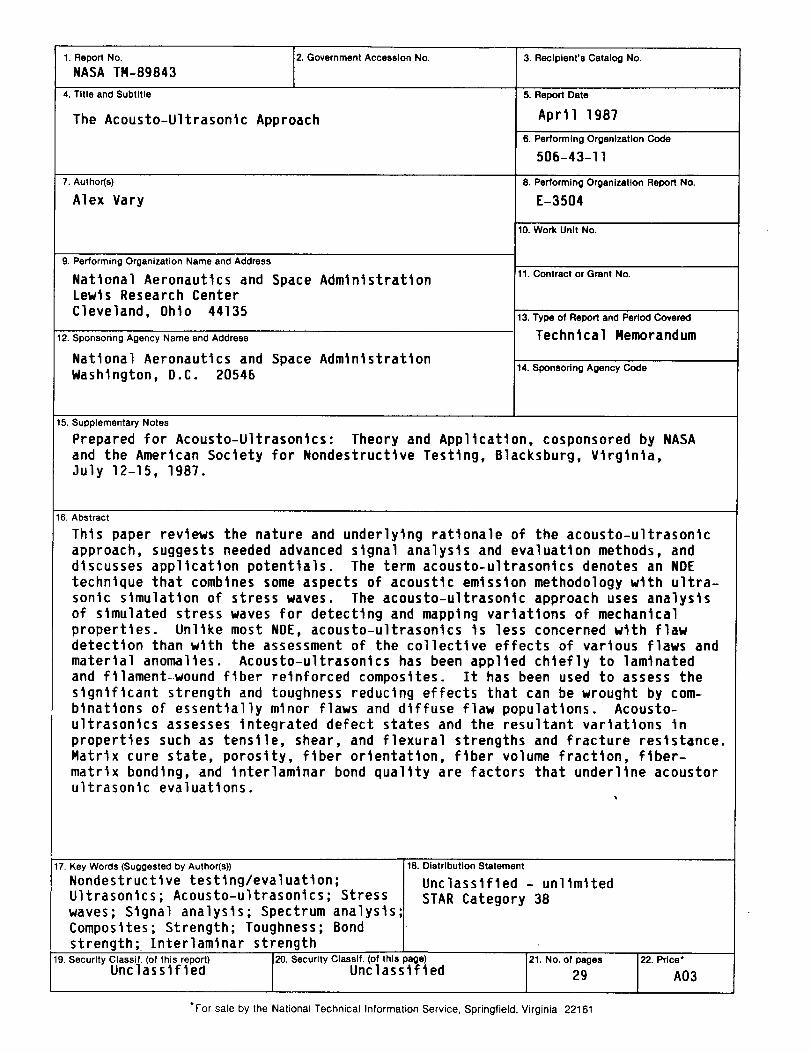
This paper reviews the nature and under]ytng rationale of the acousto-u]trasontcapproach, suggests needed advanced signal analysts and evaluation methods, anddiscusses application potentials. The term acousto-ultrasontcs denotes an NDEtechnique that combines some aspects of acoustic emission methodology with ultra-sonic simulation of stress waves. The acousto-ultrasontc approach uses analysisof stmu]ated stress waves for detecting and mapping variations of mechanicalproperties. Unlike most NDE, acousto-ultrasontcs is less concerned with flawdetection than with the assessment of the collective effects of various f]aws andmaterial anoma]tes. Acousto-u]trasontcs has been applied chiefly to laminatedand ftlament-.wound fiber reinforced composites. It has been used to assess thesignificant strength and toughness reducing effects that can be wrought by com-binations of essentially minor flaws and diffuse f]aw popu]attons. Acousto-ultrasonics assesses integrated defect states and the resultant variations inproperties such as tensile, shear, and flexural strengths and fracture resistance.Matrix cure state, porosity, fiber orientation, fiber volume fraction, fiber-matrix bonding, and tnter]amtnar bond qua]Ity are factors that underline acoustoru]trasonlc evaluations.
17. Key Words (Suggested by AuthoHs_
Nondestructive testing/evaluation;Ultrasonics; Acousto-ultrasonlcs; Stresswaves; Signal analysis; Spectrum ana]ysis;Composites; Strength; Toughness; Bondstrength; Interlaminar strength
19. Security Classif. (of this report) _. Security Classlf. (of this page) 21. No. of pages
Unclassified Unclassified 29
* For sale by the National Technical Information Service, Springfield, Virginia 22161
18. Distribution Statement
Unclassified - un]lmltedSTAR Category 38
22. Price"
A03