
THE ACCURACY AND STABILITY OF FILM RESISTORS
8
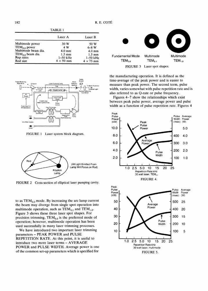
Electrocomponent Science and Technology, 1981, Vol. 8, pp. 181-187 0305-3091/81/0804-0181 $06.50/0 (C) 1981 Gordon and Breach Science Publishers, Inc. Printed in Great Britain THE EFFECT OF HIGH SPEED LASER TRIMMING ON ACCURACY AND STABILITY OF THICK FILM RESISTORS RENI E. COTt E. I. du Pont de Nemours & Company, Electronic Materials Division -Photo Products Department, Chestnut Run, Wilmington, Delaware 19898 Many recommendations have been made on the proper operating conditions for the laser trimming process. In general these recommendations have centered on accuracy, precision or throughput. In some instances, these have appeared to be mutually exclusive. If one wanted accuracy and precision, one had to sacrifice trimming speed and, therefore, throughput. It has been reported that 40% of the processing cost of a thick film resistor network is due to laser trimming. To continue to make these networks commercially attractive, the manufacturers of laser trimming systems have addressed themselves to the problem of providing suitable cuts at higher and higher trimming speeds. It is important for the user of such a system to understand the basics of the trimming process and to have an appreciation for the new factors which will affect the performance characteristics of laser trimmed thick film resistors. This paper summarizes the previous work as it relates to present technology. It then attempts to develop new guidelines for high speed laser trimming. 1. INTRODUCTION The overall subject of high speed laser trimming increases in importance as more emphasis is placed on the manufacture of resistor networks and high volume thick film hybrid circuits. It has been estimated that the laser trimming process is 40% of the cost of processing a thick film resistor network. This immediately leads the cost-reduction minded engineer to study the entire laser trimming process, especially high speed trimming. High speed laser trimming should immediately be distinguished from high throughput. High throughput can be achieved by means other than high speed. Handling and testing times are probably more significant factors in the overall trimming process. Increased automation in parts handling, as well as the use of larger substrates containing multiple circuits per substrate, will increase throughput independent of trimming speed. B+fore any logical discussion of high speed laser trimming can proceed, it is worthwhile to review some basic definitions, examine the differences which may exist between the presently available systems and, also set some meaningful guidelines. A basic laser trimming system consists of a laser, a computer control system, a resistance probing and measuring system, and a mechanism to position the 181 laser beam and move it from point to point across the substrate surface. 2. LASER At the present time, most of the trimming systems use a neodymium doped yttrium aluminum garnet (Nd-YAG) laser head which is comprised of an elliptical gold plated cavity in which the Nd-YAG laser rod is excited by a DC Krypton arc lamp. The amount of laser energy which results is primarily determined by adjustment of the arc lamp current. An acoustic Q-switch is added to the system to produce giant pulse operation which is required to obtain the necessary peak pulse energy to vaporize the thick film material. Q-switched operation provides the ability to attain peak power pulses in excess of 25 KW at pulse repetition rates of 1 to 50 kHz. Table I shows a comparison of two commonly used laser systems. A block diagram of the laser system is shown in Figure 1. A cross-section of the laser cavity is shown in Figure 2. The elliptical shape assures that all of the light, emitted from the lamp, will be concentrated on the laser rod for maximum efficiency. The laser rod can be activated to produce a fundamental output which gives a single spot, referred
Transcript of THE ACCURACY AND STABILITY OF FILM RESISTORS

Electrocomponent Science and Technology, 1981, Vol. 8, pp. 181-1870305-3091/81/0804-0181 $06.50/0
(C) 1981 Gordon and Breach Science Publishers, Inc.Printed in Great Britain
THE EFFECT OF HIGH SPEED LASER TRIMMING ONACCURACY AND STABILITY OF THICK FILM RESISTORS
RENI E. COTtE. I. du Pont de Nemours & Company, Electronic Materials Division -Photo Products Department,
Chestnut Run, Wilmington, Delaware 19898
Many recommendations have been made on the proper operating conditions for the laser trimming process. Ingeneral these recommendations have centered on accuracy, precision or throughput. In some instances, these haveappeared to be mutually exclusive. If one wanted accuracy and precision, one had to sacrifice trimming speed and,therefore, throughput.
It has been reported that 40% of the processing cost of a thick film resistor network is due to laser trimming. Tocontinue to make these networks commercially attractive, the manufacturers of laser trimming systems have addressedthemselves to the problem of providing suitable cuts at higher and higher trimming speeds.
It is important for the user of such a system to understand the basics of the trimming process and to have anappreciation for the new factors which will affect the performance characteristics of laser trimmed thick film resistors.This paper summarizes the previous work as it relates to present technology. It then attempts to develop newguidelines for high speed laser trimming.
1. INTRODUCTION
The overall subject of high speed laser trimmingincreases in importance as more emphasis is placed onthe manufacture of resistor networks and high volumethick film hybrid circuits. It has been estimated that thelaser trimming process is 40% of the cost of processinga thick film resistor network. This immediately leadsthe cost-reduction minded engineer to study the entirelaser trimming process, especially high speed trimming.High speed laser trimming should immediately be
distinguished from high throughput. High throughputcan be achieved by means other than high speed.Handling and testing times are probably moresignificant factors in the overall trimming process.Increased automation in parts handling, as well as theuse of larger substrates containing multiple circuits persubstrate, will increase throughput independent oftrimming speed.
B+fore any logical discussion of high speed lasertrimming can proceed, it is worthwhile to review somebasic definitions, examine the differences which mayexist between the presently available systems and, alsoset some meaningful guidelines.A basic laser trimming system consists of a laser, a
computer control system, a resistance probing andmeasuring system, and a mechanism to position the
181
laser beam and move it from point to point across thesubstrate surface.
2. LASER
At the present time, most of the trimming systems use aneodymium doped yttrium aluminum garnet(Nd-YAG) laser head which is comprised of anelliptical gold plated cavity in which the Nd-YAG laserrod is excited by a DC Krypton arc lamp. The amountof laser energy which results is primarily determined byadjustment of the arc lamp current.An acoustic Q-switch is added to the system to
produce giant pulse operation which is required toobtain the necessary peak pulse energy to vaporize thethick film material. Q-switched operation provides theability to attain peak power pulses in excess of 25 KWat pulse repetition rates of 1 to 50 kHz. Table I shows acomparison of two commonly used laser systems.A block diagram of the laser system is shown in
Figure 1. A cross-section of the laser cavity is shown inFigure 2. The elliptical shape assures that all of the
light, emitted from the lamp, will be concentrated onthe laser rod for maximum efficiency.The laser rod can be activated to produce a
fundamental output which gives a single spot, referred
182 R.E. COTt
TABLE
Laser A Laser B
Multimode power 30 W 50 WTEM0,0 power 4 W 6-8 WMultimode beam dia, 4.0 mm 4.0 mmTEM0,0 beam dia. 1.5 mm 1.5 mmRep rates 1-50 kHz 1-50 kHzRod size 4 x 50 mm 4 75 mm
Fundamental Mode MultimodeTEMo,o TEMo.1
FIGURE 3 Laser spot shapes.
MultimodeTEMI,o
Safety
Totally Reflecting
"J’.. | | Aperture
L]" "’’. t ]- " "L ght
J L Part,ally Retlect,ng
II’ Closed Loop’ ’11Inlp
Pump
........ ..... /f
UU"’1’’...... g)
FIGURE Laser system block diagram.
the manufacturing operation. It is defined as thetime-average of the peak power and is easier tomeasure than peak power. The second term, pulsewidth, varies somewhat with pulse repetition rate and isalso referred to as Q-rate or pulse frequency.
Figures 4-7 show the relationships which existbetween peak pulse power, average power and pulsewidth as a function of pulse repetition rate. Figures 4
PeakPulsePower(kW)
10,0
6.0
PeakPulsePower
Pulse AverageWidth Power(nsec/ (W)
5.0
400 4.0
300 3.0
Ro’d (All Light Emitted FromLamp Will Focus on Rod)
FIGURE 2 Cross-section of elliptical laser pumping cavity.
to as TEM0,0 mode. By increasing the arc lamp currentthe beam may diverge from single spot operation intomultimode operation, such as TEM0,1 and TEM1,0.Figure 3 shows these three laser spot shapes. Forprecision trimming, TEM0,0 is the preferred mode ofoperation; however, multimode operation has beenused successfully in many laser trimming processes.We have introduced two important laser trimming
parameters- PEAK POWER and PULSEREPETITION RATE. At this point, it is useful tointroduce two more laser terms- AVERAGEPOWER and PULSE WIDTH. Average power is oneof the common set-up parameters which is specified for
4.0
2.0
PeakPulsePower(kVV)
50
40
3O
20
10
1.0 2.5 5.0 10 15Repetition Rate kHz30 watt laser, TEMo,o
FIGURE 4.
20
1.0 2.5 5.0 10 15 20 25Repetition Rate kHz30 watt laser, multimode
FIGURE 5.
200 2.0
100 1.0
25
Pulse AverageWidth Power(nsec) (W)
500 25
400 20
300 15
200 10
100 5

LASER TRIMMING OF THICK FILM RESISTORS 183
PeakPulsePower(kW)
10.0
8.0
6.0
4.0
2.0
AveragePower
Power
1.0 2.5 5.0 10 15Repetition Rate kHz50 watt laser, TEMo.o
FIGURE 6.
Pulse AverageWidth Power(nsec) (W)
500 8.0
400 6.0
300 4.0
200 2.0
100 1.0
20 25
PeakPulsePower(kW)
50
4O
3O
2O
10
PeakPulse
Pulse AverageWidth Power(nsec) (W)
5OO 50
400 40
300 30
200 20
100 10
1.0 2.5 5.0 10 15 20 25Repetition Rate kHz50 watt laser, multimode
FIGURE 7.
and 5 are given for the 3 W laser while Figures 6 and 7are those for the 50 W laser. For maximum resistorstability the peak pulse power should be maximizedwith relation to the average power. This assures thatmore of the laser energy per pulse is available for theremoving of material and less energy is lost inundesired heating of adjacent resistor and substratematerial.
3. BEAM POSITIONER
Two basic methods are presently used to position thelaser beam and move it from point to point across thesubstrate. One method employs galvanometer driven"X" and "Y" mirrors as depicted in Figure 8. Thismethod is very responsive and has accelerations of up
Beam Expander(Up-Collimator)(Telescope) ,.X-Galvo
ObjectEyepiece
)bjective ZT-.’ Ix’Mirrr TO TV
I Microscope
ic Mirror
Optical Path Through Beam Positioner Cutting Lens
//FIGURE 8 Galvanometer driven "X" + "Y" mirrors.
to 200G’s. The other consists of "X" and "Y" armsactivated by directly-coupled voice coil linear actuators.This method is shown pictorially in Figure 9. The linearactuators have high positional accuracy andrepeatability and accelerate up to approximately 20G’s.On the basis of acceleration alone, the galvanometer
driven mirrors appear capable of higher trimmingspeeds, although it may be argued that the throughputof either system can be optimized to be quite similar.
Incorporated into the beam positioner is a focusingdevice to concentrate the beam power onto the surfaceof the thick film material. The focusing lens of typicalthick film optics have a rating of f30 which results in abeam waist theoretically capable of achieving a 30 #mspot size. Practically, however, the minimum spot size iscloser to 50 pm. The depth of field for these optics is
conioleKryptonlamp*
,,laser___beam -’ \\
:;:re* [m,ror or
focusQ-switch*
comutrr6e
teletypecommand &data log
*controllable variables
FIGURE 9.

184 R.E. COTI
approximately 400 pm. Thus, it is important to refocusthe beam when going from one substrate thickness toanother.
4. MECHANICS OF THE LASER CUT
The subject of how laser pulses are produced,positioned and then moved over the substrate surfacehas been discussed. Now the mechanics of laser cutsshould be considered. Making clean laser cuts beginswith properly processed thick films. Shah and Berrin1
of Bell Telephone Laboratories have discussed theimportance of controlling film thickness. Lasertrimming is a physical process concerned with removingmaterial by vaporization. The integrity of the remainingfilm is dependent on the cleanliness of the cut and theamount of damage incurred. Excessive damage resultswhen too much power, at less than vaporization levels,is allowed to affect a given area. It therefore becomesimportant to carefully control the absolute peak energyof each pulse and the speed at which they travel acrossthe surface of the material being removed.
Figure 10 shows how a typical laser cut may beproduced at two different speeds or even at the samespeed for two different pulse rates. Figure 10a shows acut made with an overlap of 50%. This is considered theminimum overlap which should be used to produceuniform, high quality cuts. Figure 10b shows less than10% overlap. This can produce ragged, irregular cuts,often of insufficient depth.
Overlap also becomes an important factor in theaccuracy or precision which can be obtained from thelaser trimming process. If an overlap of 50% is beingused and the pulse has a diameter of 50 pm, each pulsetakes a 25 pm bite out of the resistor being trimmed. Ifsmall resistors are being trimmed to value, the accuracyis very dependent on the extent of trimming.
Bite Size---.[
Time
FIGURE 10a.
I---wo---I Trim Characteristic*
L :xl- One Square--P Cut
______/ &R 10%/ r4 h (1 mm) /
. [-(1 lm) ’*--&X 25. (25- 2.mm)
(25 2.5mm) - [;’i !--&X 25#(11 ram)
/ 1AX S. (2.S 2.5 mm) *Birox" 1431
0 66 7 80 83.3 8.7 875 889 00
rct o[ sistor tratio (c/o 00}
FIGURE 11.
Figure 11 shows this graphically. It compares ai mm resistor to a 2.5 mm resistor. It shows thatwhen a 1 mm resistor has its value raised 1.4 x thefired value, one extra pulse resulting in 25 pmextension of the cut changes the value 3.6%. When thevalue is raised 2.5 x the initial fired value, the samepulse will change the value approximately I0%. Thesechanges become 1.4% and 2.8% for a 2.5 mm resistor.This presumes that ach puls rmovs all th rsistormaterial directly beneath it.When high speed and high precision are equally
important, it is necessary to take all factors intoconsideration. The geometry must be selected toaccommodate the desired end results. The bite sizemust be chosen to be compatible with the trimmingspeed used. In all cases, it is assumed that the measure-ment system is capable of fast accurate tracking.
Plunge Cut Double Plunge Cut
"L"-Cut
Serpentine Cut
uRagged Kerf 8’re Size"--l
FIGURE 10b.
"L"-Cut With Double "L"-Vernier Shaped Cut
FIGURE 12 Laser cutting techniques.

LASER TRIMMING OF THICK FILM RESISTORS 185
There are several ways of cutting a resistor duringthe laser trimming operation. Figure 12 illustrates sixmethods of trimming square and rectangular geo-metries. The plunge cut is the fastest and most usedconfiguration for reasonable accuracy and stability.When greater initial accuracy is required, the "L" cutoffers more advantage at only a slight decrease inspeed. All of the multiple cuts except the serpentine areusually made with a delay between the first cut (A) andthe second cut (B). The amount of delay varies fromsituation to situation, but usually the first cut is made inall of the resistors on the substrate and then,immediately after, the second cut is made withoutremoving the part from the system. The first cut adjustsresistance value to --98% of the target value; the finaladjustment to the desired cut-off value is completedduring the second cut.
0.4 Kerf I.R. <2 109D.
0.3
0.2Maximum % 3R Average % AR
0.1
10 100Cutting Power
FIGURE 13 Parametric trim study 1000f/Z] 100 hourpost trim %AR.
5. OPTIMIZING FOR HIGHER TRIMMINGSPEEDS
In order to trim at higher speeds, the laser system mustachieve the desired speed in the prescribed amount oftime. In other words, it must generate the necessarynumber of pulses per unit of linear travel at that speed,and it must deliver the necessary amount of peak pulseenergy to remove material.
In order to be able to talk more objectively aboutlaser trimming parameters, other basic laser trimmingterms must be defined:
0.7
0.6
0.5
0.4
0.3
0.2
0.1
Kerf I.R. <2 109 /Maximum
//10 100
Cutting Power
FIGURE 14 Parametric trim study 10Kf/E] 100 hour posttrim %hR.
P Average Beam Power (Q-Switched Mode)Q Pulse FrequencyS Trimming SpeedLinear Energy Density (LED) P/S
(Joule/mm)Linear Pulse Density (LPD) Q/S
(pulse/mm)Cutting Power (CP) LED LPD Joule
(pulse/mm2)Having defined the term cutting power, experiments
were run using Du Pont Series 17 resistorcompositions. Low ohm material (100f/Z]) and highohm material (10Kf/E3) were cut at various averagebeam powers, pulse frequencies and trim speeds. Theinsulation resistance of a 1 mm resistor, which was cutcompletely through, was measured at 200V. It wasdetermined that an initial insulation resistance greaterthan 2 109 ohms was necessary to produce a stablecut. Figures 13 and 14 show the graphical results of thisstudy.
For the 100)/E3 material, a cutting power of 10joule pulse/mm2 was necessary; for the 10Kf/[]material, necessary cutting power was reduced to 6joule pulse/mm2. Thus, a cutting power of 15 joulepulse/mm2 is sufficient to produce trimmed resistors ofeither type with good end of life stability. If one uses aminimum of 120 pulses per mm to assure clean cuts, itthen becomes possible to calculate the pulse frequencyand average power which must be used to achieve adesired trimming speed.
Figure 15 shows the shape of the acceleration curvefor the linear actuator type of beam positioner. At100 mm/sec trimming speed, 0.4 mm are required tocome up to full trimming speed and the same 0.4 mm todecelerate to 0 velocity. If a distance limit stop is used,0.4 mm are required to come to full speed andapproximately 1 mm to decelerate. This limits theoverall speed achieved during the trimming operationfor this type of beam positioner. A method ofincreasing throughput time is to come up toacceleration and trim all resistors without decelerating

186 R.E. COTt
Velocity Profile
I- tv/l ].---- t..1_
’,=
\x
V=O Sto Distance kimit Sto
100
0.1
11 II IIII IIIL 0.0110 100mm
IlVlJlll 11.11
10 100mm
sec sec
FIGURE 15 Velocity profile for direct-coupled voice linear actuator.
by turning the laser on and off as one goes from resistor
to resistor without stopping.In the case of average pulse power and pulse
frequency, the commonly used lasers are currentlylimited to 50 watts multimode operation or 8W TEM0,0
and 50 kHz maximum switch frequency.Keeping these stated limitations in mind and
recalling the equation for cutting power, it is possible to
calculate the average power and pulse frequencyrequired to produce satisfactory laser cuts at variouslaser trimming speeds. For Series 17 resistors, we cancalculate these parameters for cutting powers of 6, 10
TABLE II
Cutting power LPD x LED Q/S eavg/Swhere Pavg joules/sec
(1) Q 120S (Hz)(2) Pavg 0.05S (watts) at cutting power 6
0.083S (watts) at cutting power 100.125S (watts) at cutting power 15
power (watts)
Speed Frequency(mm/sec) (kHz) CP 6 CP 10 CP 15
10 1.2 0.5 0.83 1.2556 6 2.5 4.15 6.25100 12 5 8.3 12.5500 60 25 41.5 62.5
and 15 joule pulse/mm2. The results are shownin Table II. Recall that 120 pulses per mm are requiredto assure complete cutting.
These calculations show that to operate in TEM0,0
mode, the practical speed limit is approximately100 mm/sec. If higher speeds are required, multimodeoperation must be accepted. Refer to Charts 4--7 forspecifics. If one is satisfied with a minimum of 50%overlap which is 40 pulses per mm, instead of 120, thenthe conditions are shown in" Table III.
It still appears as though the practical trimming speedis 100 mm/sec to maintain TEM0,0 mode.
TABLE III
Cutting power LPD x LFD Q/S Pavg/Swhere Pavg joules/sec
(1) a 80S (Hz)(2) Pavg 0.07S (watts) at cutting power 6
0.125S (watts) at cutting power 100.185S (watts) at cutting power 15
power (watts)Speed Frequency(mm/sec) (kHz) CP 6 CP 10
10 0.8 0.75 1.2550 4.0 3.75 6.25100 8.0 7.5 12.5500 40 37.5 62.5
1.859.25
18.592.5

LASER TRIMMING OF THICK FILM RESISTORS 187
6. CONCLUSIONS ACKNOWLEDGEMENTS
The entire subject of high speed laser trimming must beconsidered very carefully so that adequate accuracy andstability of the trimmed resistors are maintained. Thelaser system must be capable of achieving the necessarypeak pulse power and pulse frequency necessary toremove the material cleanly. The beam positioner mustbe capable of achieving the necessary acceleration andrunning speeds to correspond with the machinesettings. The substrate must be designed and processedto make the entire process feasible and reproducible.Based on experiments run with the Series 17, cutting
power of 10 joule pulse per mm2 is required toproduce stable end-of-life resistors. To assure completeremoval of material, 120 pulses per mm should be used.In no case should less than 40 pulses per mm be usedbecause an overlap of only 50% results at this rate,assuming a properly focused beam of 50/m indiameter.
Since the laser trimming process is basically amechanical method for the removal of material, the lessmaterial there is to remove, the faster the process.Resistor thickness should be optimized and the screenprinting and firing process should be controlled toassure reproducible results. If a resistor overglaze isused, this must be accounted for as additional materialwhich must be removed, and the laser parameters mustbe adjusted accordingly.
The author wishes to acknowledge Ronald C. Headley for hisvaluable inputs and for his assistance in reviewing thismanuscript.
Figures 1, 2 and 8 courtesy of Chicago Laser systems.Figures 4, 5, 6 and 7 courtesy of Central Laser Corporation.
BIBLIOGRAPHY
R. T. Howard and R. V. Allen, Characterization of LaserTrimmed Thick Film Resistors by Scanning ElectronMicroscopy, Proceedings ISHM (1971).
R. C. Headley, M. J. Popowich and F. J. Anders, YAG LaserTrimming of Thick Film Resistors, IEEE Symposium(March, 1973).
R. E. Cot6, R. C. Headley, J. T. Herman and A. Howe,Factors Affecting Laser-Trim Stability of Thick FilmResistors, Proceedings ISHM (1976).
J. R. Larry, M. J. Popowich, R. C. Headley and R. M.Rosenberg, A New High Stability Resistor System,Proceedings Electronic Components Conference (1977).
An Introduction to Laser Trimming, Chicago Laser Systemspublication.
R. Conradt and L. S. Marcus, Thick Film Laser Trimming-Principles, Techniques and Recommendations, CircuitsManufacturing (October, 1979).
Laser Trimming Throughput, Tetradyne publication (1978).A. G. Albin and E. J. Swenson, Laser Resistor Trimming from
the Measurement Point of View, Proceedings ElectronicComponents Conference (1971).
M. B. Davies, J. B. Willis and J. K. Wright, The Use of Lasersfor Resistor Trimming, ISHM (UK) Conference (1971).
J. S. Shah and L. Berrin, Mechanism and Control of Past-TrimDrift of Laser Trimmed Thick Film Resistors, IEEETransactions (June, 1978).

International Journal of
AerospaceEngineeringHindawi Publishing Corporationhttp://www.hindawi.com Volume 2010
RoboticsJournal of
Hindawi Publishing Corporationhttp://www.hindawi.com Volume 2014
Hindawi Publishing Corporationhttp://www.hindawi.com Volume 2014
Active and Passive Electronic Components
Control Scienceand Engineering
Journal of
Hindawi Publishing Corporationhttp://www.hindawi.com Volume 2014
International Journal of
RotatingMachinery
Hindawi Publishing Corporationhttp://www.hindawi.com Volume 2014
Hindawi Publishing Corporation http://www.hindawi.com
Journal ofEngineeringVolume 2014
Submit your manuscripts athttp://www.hindawi.com
VLSI Design
Hindawi Publishing Corporationhttp://www.hindawi.com Volume 2014
Hindawi Publishing Corporationhttp://www.hindawi.com Volume 2014
Shock and Vibration
Hindawi Publishing Corporationhttp://www.hindawi.com Volume 2014
Civil EngineeringAdvances in
Acoustics and VibrationAdvances in
Hindawi Publishing Corporationhttp://www.hindawi.com Volume 2014
Hindawi Publishing Corporationhttp://www.hindawi.com Volume 2014
Electrical and Computer Engineering
Journal of
Advances inOptoElectronics
Hindawi Publishing Corporation http://www.hindawi.com
Volume 2014
The Scientific World JournalHindawi Publishing Corporation http://www.hindawi.com Volume 2014
SensorsJournal of
Hindawi Publishing Corporationhttp://www.hindawi.com Volume 2014
Modelling & Simulation in EngineeringHindawi Publishing Corporation http://www.hindawi.com Volume 2014
Hindawi Publishing Corporationhttp://www.hindawi.com Volume 2014
Chemical EngineeringInternational Journal of Antennas and
Propagation
International Journal of
Hindawi Publishing Corporationhttp://www.hindawi.com Volume 2014
Hindawi Publishing Corporationhttp://www.hindawi.com Volume 2014
Navigation and Observation
International Journal of
Hindawi Publishing Corporationhttp://www.hindawi.com Volume 2014
DistributedSensor Networks
International Journal of