The ABC's of Spray Painting - InfoHouseinfohouse.p2ric.org/ref/27/26539.pdf · this leadership...
27
I DEVILBISS The ABC's of Spray Finishing A working guide to the selection and use of spray finishing equipment
Transcript of The ABC's of Spray Painting - InfoHouseinfohouse.p2ric.org/ref/27/26539.pdf · this leadership...

I DEVILBISS
The ABC's of Spray Finishing A working guide to the selection and use of spray finishing equipment
While this book examines the spray finishing operation and its equip- ment from many viewpoints, there is still much more to be learned to become truly proficient at spray finishing.
The best way to become profi- cient at spray finishing is to just do it! Many trade, technical and com- munity colleges offer courses in spray finishing, a great way to im- prove your skills.
Many of the "tricks" of the pro- fessional spray finisher involve paints and coatings. The manufac- turers of these materials routinely publish complete books on these subjects. These publications are available in specialty paint stores and will provide you with consid- erable detail. Many of these books also contain information on tech- niques for surface preparation.
Another important source of in- formation, particularly on equip- ment use and selection, is your lo- cal spray finishing equipment dis- tributor. No book could ever com- pletely cover a specialist's in-depth knowledge of the equipment, the techniques, the maintenance and troubleshooting.
able on the subject of spray finish- ing. It is our hope that this book provides you with a start toward perfecting your finishing skills.
There is much information avail-
About This Book ... This-book has been updated sever- al times from "The ABC's of Spray Equipment," originally published by The DeVilbiss Company in 1954. This version focuses on equipment and techniques for the industrial finisher. Another version is avail- able that is directed to the automo- tive refinisher.
The format of the original book was question-and-answer. We have retained that format in this edition.
This book is organized around the major components of an air spray system ... spray guns, material containers, hose, air control equip- ment, compressors, spray booths, respirators and a short section on general cleanliness and other sources of information. A thorough understanding of the material in this book - plus a lot of actual spray painting practice - should enable you to handle just about any spray painting situation.
Although we have made an ef- fort to make this book as detailed and as complete as possible, be aware that the equipment and product systems used to illustrate points are entirely based on DeVilbiss technology. DeVilbiss is the world's oldest and largest manufacturer of spray painting equipment, and has maintained this leadership since its founding in 1888.
2
4 Foreword . . . . . . . . . . . . . .. . .. . . . . . . . . . . . . . . . . . , . . .2
4 Hose and Ca
4 Air Regulator ........................... 21
s may bc quoted o r

This book is about the selection, use and maintenance of finishing equipment: spray guns, tanks, cups, hoses, compressors, regula- tors, spray booths, respirators, etc. It presumes that you are familiar with standard surface preparation techniques which may be required before finishing actually begins. It also presumes a basic knowledge of the many different types of paints and coatings available.
Creating a perfect finish requires a solid knowledge of surface prepa- ration, finishes and spray painting equipment. The first two are exten- sively covered in many other books. The manufacturers of paints and coatings have gone to great lengths to publish informa- tion on their new and existing products.
But, even an extensive knowl- edge of surface preparation tech- niques and paint chemistry is not enough to assure a professional fin- ish. The finish must still be applied by a spray gun, and all of the vari- ables of its use must be mastered.
The equipment necessary to ap- ply the finish - the spray gun, tank, cup, regulator, hoses, compressor, etc. - must all be matched to the job as well as to each other. That equipment must be used and main- tained properly, with an apprecia- tion of how and why it works the way it does.
ish happens when the trigger is pulled. This book focuses on that moment. Surface Preparation The surface to be finished should be well cleaned before painting. If the paint manufacturer’s instruc- tions call for it, the surface should be chemically treated. Use a blow- off gun and tack rag to remove all dust and dirt. No amount of primer or paint will cover up a badly pre- pared surface.
Plastic parts may contain static electricity from the molding process. This static attracts particles of dust and dirt. Eliminate them by
1
The moment of truth for any fin-
1
treating with ”destatisizing” air us- ing a special blow-off gun which imparts a neutral charge to the air flow. Paint Preparation Today’s finishes are extremely complex, chemical formulations. They include both solvent and wa- terborne types. Some may require the addition of solvents to form the proper spraying viscosity. 0th- ers may simply require the addi- tion of a second component at a prescribed ratio to obtain sprayable consistency. Many of them also have hardeners, or other chemicals, added to them to insure correct col- or match, gloss, hardness, drying time or other characteristics neces- sary to produce a first class finish. Make sure you are familiar with the specific finish material data sheets accompanying each materi- al. Read and follow directions care-
All finish materials must also be supplied with Material Safety Data Sheets (MSDS). This data provides information on proper handling and disposal of materials. Many states require that MSDS be kept on file by the user.
The first step is knowing the type and color of paint the project re- quires.
With these determined, follow the manufacturer’s instructions for preparing it exactly. If you have any doubts about how to proceed, don’t guess! Contact your paint supplier for help. Improperly pre- pared paint will never produce a good finish!
The chief characteristic that de- termines the sprayability of paint, and how much film may be ap- plied, is its viscosi ty... or consisten- cy. Following the paint manufac- turer’s instructions will get you close, but for professional results, use a viscosity cup. It is a simple, but very accurate, way to measure the thickness of paint. With the cup, you can thin or reduce the paint to the precise consistency re- quired by the manufacturer.
fully.
Always prepare paint in a clean, dust-free environment. Paint has a remarkable ability to pick up dirt. Dirty paint will not only clog your spray gun, but it will also ruin your paint job. Get in the habit of al- ways pouring paint into the cup or tank through a paint strainer. Paint is never as clean as it looks.
3

Introduction The spray gun is the key compo- nent in a finishing system. It is a precision engineered and manufac- tured instrument. Each type and size is specifically designed to per- form a certain, defined range of tasks.
As in most other areas of finish- ing work, having the right tool for the job goes a long way toward get- ting professional results.
This chapter will help you know which is the proper gun by review- ing the Conventional Air and High- Volume/Low Pressure spray gun designs commonly used in finish- ing - suction feed, gravity feed and pressure feed. It will also review the different types of guns and components within each design.
A thorough understanding of the differences between systems will allow you to select the right gun, to use it properly to produce a high quality finish and to con- tribute toward a profitable finish- ing operation. SPRAY GUN TYPES 1. What is an air spray gun? An air spray gun is a tool which us- es compressed air to atomize paint, or other sprayable material, and to apply it to a surface.
Air and material enter the gun through separate passages, and are mixed at the air cap in a controlled pattern. 2. What are the types of air spray guns? Air spray guns may be classified in various ways. One way is by the location of the material container:
Figure 1 shows a gun with a cup attached below it.
Figure 3 shows a gun with a cup attached above it.
Figure 4 shows a material con- tainer some distance away from its pressure feed gun.
The type of material feed system is also a way of classifying guns: Suction Feed ... draws material to the gun by suction as in Figure 1.
Gravity Feed ... the material travels down, carried by its own weight as in Figure 3. Pressure Feed ... the material is fed by positive pressure as in Figure 4.
Guns may also be classified as either external or internal mix. 3. What is a suction feed gun? A spray gun design in which a stream of compressed air creates a vacuum at the air cap, providing a siphoning action. Atmospheric pressure on the material in the suc- tion cup forces it up the suction tube, into the gun and out the fluid tip, where it is atomized by the air cap. The vent holes in the cup lid must be open. This type gun is usu- ally limited to a one-quart, or smaller, capacity container.
Figure 1 - Suction Feed Gun with attached cup Suction feed is easily identified by the fluid tip extending slightly be- yond the face of the air cap, as shown in Figure 2.
t u t Figure 2 - Suction Feed Air Cap
Suction feed guns are suited to many color changes and to small amounts of material, such as in touchup or lower production oper- ations. 4. What is a gravity feed gun? This design uses gravity to flow the material from the cup, which is mounted above the gun, into the gun for spraying. No fluid pick- up tube is used, since the fluid out- let is at the bottom of the cup.
This cup has a vent hole at the top of the cup which must remain open. It is limited to 1/2-pint or 1- pint capacities due to weight and balance.
Gravity feed guns are ideal for small applications such as spot re- pair, detail finishing or for finish- ing in a limited space. They require less air than a suction feed gun, and usually have less overspray.
Figure 3 - Gravity Feed Gun with cup on top
4

5. What is a pressure feed gun? .’ In this design, the fluid tip is flush with the face of the air cap (see Fig- ure 5). The material is pressurized in a separate cup, tank or pump. The pressure forces the material through the fluid tip and to the air cap for atomization.
Figure 4 - Typical Pressure Feed Gun with remote cup
This system is normally used when large quantities of material are to be applied, when the materi- al is too heavy to be siphoned from a container or when fast applica- tion is required. Production spray- ing in a manufacturing plant is a typical use of a pressure feed sys-
!
tem.
Ail r Ca
t u t Figure 5 - Pressure Feed Air Cap
6. What is an external mix gun? This gun mixes and atomizes air and fluid outside the air cap.
It can be used for applying all types of materials, and it is particu- larly desirable when spraying fast- drying paints such as lacquer. It is also used when a high aualitv fin- ish is dc
Figure 6 - External Mix Gun 7. What is an internal mix gun? This gun mixes air and material in- side the air cap, before expelling them.
It is usually used where low air pressures and volumes are avail- able, or where slow-drying materi- als are being sprayed.
A typical example is spraying flat wall paint, or outside house paint, with a small compressor.
Internal mix guns are rarely used for finishing when a fast-dry- ing material is being sprayed, or when a high quality finish is re-
8. What is HVLP? HVLP, or High-Volume/Low- Pressure, uses a high volume of air (typically between 15-22 CFM) de- livered at low pressure (10 PSI or less) to atomize paint into a soft, low-velocitv Dattern of Darticles.
Figure 8 -Typical HVLP System (High-Volume/Low-Pressure ) with at- tached pressure cup
As a result, far less material is lost in overspray, bounceback and blowback than with conventional air spray. This is why HVLP deliv- ers a dramatically higher transfer efficiency (the amount of material that is actually applied to the part) than higher pressure spray sys- tems.
The HVLP spray gun resembles a standard spray gun in shape and operation. Some models, particu- larly those using turbines to gener- ate air, bleed air continuously to minimize back pressure against the
5

air flow of the turbine. The air cap design is similar to
that of a standard spray gun, with a variety of air jets directing the at- omizing air into the fluid stream, atomizing it as it leaves the tip.
and it has also been judged envi- ronmentally acceptable due to its high transfer efficiency.
HVLP can be used with any low-to-medium solids materials that can be atomized by the gun, including two-component paints, urethanes, acrylics, epoxies, enam- els, lacquers, stains, primers, etc.
There is one design available to- day which can atomize higher vis- cosity andlor higher fluid flow materials than has previously been possible with HVLP. It uses a spe- cially designed air cap, fluid tip and baffle. (DeVilbiss Maximum Per- former) PART IDENTIFICATION FUNCTION 9. What are the principal parts of a spray gun? The principal components are illus- trated in Figure 9. Some guns are equipped with a removable spray- head unit containing the air cap, baffle, fluid tip, fluid needle pack- ing and packing nut.
HVLP is growing in popularity
Figure 9 - The Anatomy of a Spray Gun
I O . What happens when the trigger is pulled? The trigger operates in two stages. Initial trigger movement opens the air valve, allowing air to flow through the gun.
opens the fluid needle, allowing fluid material to flow. When the trigger is released, the fluid flow stops before the air flow.
operation, assures a full spray pat- tern when the fluid flow starts. It also assures a full pattern until the fluid flow stops, so there is no coarse atomization. 11. What is the function of the air cap? The air cap (see Figures l l a & b) directs compressed air into the flu- id stream to atomize it and form the spray pattern. (see Figure 10)
There are various styles of caps to produce different sizes and shapes of patterns for many appli- cations. rapsred
Further movement of the trigger
This lead/lag time in the trigger
81JM
Figure 10 - Types of Spray Patterns 12. What are the air cap classifications? All air caps can be divided into ex- ternal or internal mix classifica- tions.
External mix caps are used with either suction or pressure feed sys- tems. They eject air through one or more holes to atomize the material outside the gun cap (see Figure lla). External mix caps range from single orifice types to multiple jet caps. They are normally used in finishing work where a high quali- ty finish is required.
Figure 1 la - External Mix Air Cap
material inside the air cap, before ejecting them through a single elongated slot. (see Figure l lb)
Internal mix caps are used only with pressure feed systems. Atom- ization air and material pressure must be approximately equal at the gun. They are normally used in finishing work where a high quali- ty finish is not required.
Internal mix air caps mix air and
Figure I l b - Internal Mix Air Cap 13. What are the advantages of the multiple jet cap? This cap design provides better at- omization of more viscous materi- als.
It allows higher atomization pressures to be used on more vis- cous materials with less danger of split spray pattern.
pattern due to better equalization of air volume and pressure from the cap.
tion for materials that can be sprayed with lower pressures.
It provides greater uniformity in
It also provides better atomiza-
M t x Air Cap
6

14. How should an air cap be selected? The following factors must be con- sidered: a) type and volume of material to be sprayed b) size and nature of object, or sur- face, to be sprayed (Multiple, or larger, orifices increase ability to atomize more material for faster painting of large objects. Fewer, or smaller, orifices usually require less air, produce smaller spray pat- terns and deliver less material. These caps are designed for paint- ing smaller objects and/or using slower speeds.) c) material feed system used - pressure, suction or gravity d) size of fluid tip to be used (Most air caps work best with certain flu- id tip/needle combinations.) e) volume of air in cubic feet per minute (cfm) and pressure in pounds per square inch (psi) avail- able
See the DeVilbiss Catalog 1-2008 for the proper selection of air cap I fluid tip I needle combinations and typical uses. 15. What is the function of the fluid tip and needle? They restrict and direct the flow of material from the gun into the air stream. The fluid tip forms an in- ternal seat for the tapered fluid needle, which reduces the flow of material as it closes. (see Figure 13)
The amount of material which leaves the front of the gun depends upon the viscosity of the material, the material fluid pressure and the size of the fluid tip opening pro- vided when the needle is unseated from the tip.
Fluid tips are available in a vari- ety of sizes to properly handle ma- terials of various types, flow rates and viscosities.
!
Figure 13 - The Fluid Tip and Needle 16. What is the nozzle combination? In practice, the air cap, fluid tip and needle are selected as a unit, since they all work together to pro- duce the quality of the spray pat- tern and finish. These three items, as a unit, are referred to as the noz- zle combination. 17. What are the standard fluid tip sizes and flow rates? The standard sizes, corresponding fluid tip opening dimensions and flow rates are:
A rule of thumb for pressure feed svstems is:
Optimumfluid pressures are 15-20 psi. Pressures greater
than this generally indicate the need for a largerfluid tip size.
18. How are fluid tip and needle sizes identified? DeVilbiss fluid tips and needles are identified by the letter stamped on the tip and the needle.
The identification letters on these components should match. See the DeVilbiss Catalog 1-2008 for the proper selection of fluid tip and needle combinations. 19. What fluid tip and needle combination sizes are most common? E, EX, FF and FX are most general- ly used. The EX combination is used for suction feed, while the other sizes are commonly used for pressure feed. 20. How are nozzle combinations selected?
Five basic considerations are in- volved in selecting the nozzle com- bination:
type and viscosity of material
physical size of object being
desired speed/finish quality gun model being used available air volume (cfm) and pressure (psi) from compressor
material being sprayed is the first factor to consider.
being sprayed
finished
(1) The type and viscosity of the
A good rule of thumb is:
The lower the viscosity of the material, the smaller the I.D. of
the fluid tip.
7

(2) The physical size of the ob- ject to be painted must also be con- sidered. As a general rule, use the largest possible spray pattern con- sistent with the object size. Remem- ber that different air caps deliver various pattern characteristics. This can reduce both spraying time and the number of gun passes.
(3) The next consideration in evaluating nozzle combinations is the speed with which the finish will be applied, and the desired level of quality.
For speed and uniform cover- age, choose a nozzle combination which produces a pattern as wide as possible.
For finish coat work, quality is the deciding factor. Choose a noz- zle combination which produces a fine atomization and a smaller pat- tern size, thereby giving greater ap- plication control.
(4) The model of the gun itself will limit the selection of nozzle combination.
For a DeViibiss suction feed gun, there are two nozzle types available which are suitable for finishing operations. These nozzles have fluid tip openings of .070" and .086", and are designed to handle viscosities from 25 to 40 seconds in a No. 2 Zahn Viscosity Cup.
For a DeVilbiss pressure feed gun, the amount of material dis- charged depends upon material vis- cosity, the inside diameter of the fluid tip, the length and size of hose and the pressure on the material container or pump.
If the fluid tip opening is too small, the paint stream will be too high. If the fluid tip opening is too large, you will lose control over the material discharging from the gun.
For HVLP guns, the paint flow shouldn't exceed 16 oz. per minute.
NOTE: Viscosity conversion charts are available to convert one viscosity cup reading to another from any material or equipment supplier.
(5) Available air supply is the last factor to consider.
Pressure feed air caps consume between 7.0 and 25.0 CFM, depend- ing on air pressure applied. If your air supply is limited, because of an undersize compressor, or many other air tools are in use at once, the gun will be starved for air, pro- ducing incomplete atomization and a poor finish. 21. What are the criteria for selecting a pressure feed nozzle? While the fluid discharge in ounces per minute from a suction feed gun is relatively stable (largely be- cause it is determined by atmos- pheric pressure), the fluid dis- charge from a pressure feed gun depends more upon the size of the inside diameter of the fluid tip and the pressure on the paint container or pump. The larger the opening, the more fluid is discharged at a given pressure.
the amount of material flowing from the gun, the discharge veloci- ty will be too high. The air, coming from the air cap, will not be able to atomize it properly causing a cen- ter-heavy pattern.
If the fluid tip opening is too large, material discharge control will be lost.
The fluid tip/air cap combina- tion must be matched to each other and to the job at hand. Spray gun catalogs include charts to help you match them properly. 22. Of what metals are fluid tips made? Tips are made of the following met- als: a) 300-400 grade stainless steel for both non-corrosive and corrosive materials
If the fluid tip ID is too small for
b) Carboloy inserts for extremely abrasive materials 23. What is viscosity? The viscosity of a liquid is its body, or thickness, and it is a measure of its internal resistance to flow. Vis- cosity varies with the type and temperature of the liquid. Any ref- erence to a specific viscosity mea- surement must be accompanied by a corresponding temperature speci- fication.
Viscosity is usually measured in poise and centipoise (lpoise=100 centipoise). The most common measurement used to determine viscosity in finishing isflow rate (measured in seconds from a Zahn, Ford or Fisher Viscosity Cup).
complished by consulting a viscosi- ty conversion chart.
Different viscosity cup sizes are used for different thicknesses of materials. Each cup has a precision hole at the bottom of the cup. Use a smaller or larger hole in the cup de- pending on the thickness of the ma- terial. Viscosity control is an ex- tremely important and effective method to maintain application ef- ficiency and quality consistency. Always measure viscosity after each batch of material is mixed and make sure material temperature is the same, normally 70' to 80' F. 24. What is the spreader adjust- ment valve? A valve for controlling the air to the horn holes which regulate the spray pattern from maximum width down to a narrow or round pattern. 25. What is the fluid needle adjustment? This adjustment controls the travel of the fluid needle, which allows more or less material through the fluid tip. See Figure 13.
Viscosity conversion may be ac- -
8

\
26. What is the "Ball and Cone" principle? A feature which assures perfect alignment between the air cap and the fluid tip. A precision-machined, conical surface on the fluid tip pro- vides a seat for the precision-ma- chined ball segment of the air cap.
1 Fluid Tip ! Figure 14 - The Ball and Cone 27. What are the advantages of a removable sprayhead? The sprayhead (an assembly con- sisting of the air cap, fluid tip, fluid needle and sprayhead body) can be quickly and easily removed, as a unit, from some spray gun bodies designs.
a) Change quickly from one color or material to another. One spray gun, with several heads, can take the place of several different guns. b) Cleaning is simple. c) If the sprayhead is damaged, a new gun body is not required. d) An extra sprayhead can be sub- stituted for one being repaired or cleaned.
The advantages are:
/ \
Figure 15 - Sprayhead Removal Puoc?dure 28. What are the components of suction and gravity feed sys- tems? Typical suction and gravity feed systems consist of; a suction feed or gravity feed spray gun with cup, an air compressor (not shown), a combination filter/air ,. regulator and air hoses.
Figure 16 - Suction Feed and Gravity Feed System Components
OPERATION 29. How is suction and gravity feed equipment hooked up for operation? Connect the air supply from the compressor outlet to the filter/air regulator inlet.
Connect the air supply hose from the air regulator outlet to the air inlet on the spray gun.
After the material has been re- duced to proper consistency, thor- oughly mixed and strained into the cup, attach the gun to the cup. 30. How are suction and gravity feed systems initially adjusted for spraying?
(1) Spray a horizontal test pat- tern (air cap homs in a vertical po- sition). Hold the trigger open until the paint begins to run. There should be even distribution of the paint across the full width of the pattern. (see Figure 17) Adjust with fan pattern adjustment. If distribu- tion is not even, there is a problem with either the air cap or the fluid tip which must be corrected. Refer to the Troubleshooting Section for examples of faulty patterns to help diagnose your problem.
Figure 17 - Horizontal Test Pattern with Even Material Distribution.
(2) If the pattern produced by the above test appears normal, ro- tate the air cap back to a normal spraying position and begin spray- ing. (Example - a normal pattern with a #30 air cap will be about 9" long when the gun is held 8" from the surface.)
screw open to the first thread, and the air pressure set at approximate- ly 30 psi, make a few test passes with the gun on some clean paper. If there are variations in particle size- specks and/or large globs - the paint is not atomizing properly. (see Figure 18)
(4) If the paint is not atomizing properly, increase the air pressure slightly and make another test pass. Continue this sequence until the paint particle size is uniform.
(3) With the fluid adjusting
-
9

Figure 18 - Pattern with Uneven Particle Size.
(5) If the pattem seems starved for material, and the fluid adjusting screw is open wide (to the first thread), the atomization air pres- sure may be too high, or the mater- ial may be too heavy. Recheck the viscosity or reduce the air pressure.
(6) If the material is spraying too heavily and sagging, reduce the material flow by turning in the flu- id adjusting screw (clockwise). 31. What are the components of a pressure feed system? A pressure feed system consists of; a pressure feed spray gun, a pres- sure feed tank, cup or pump, an air filter/regulator, appropriate air and fluid hoses and an air com- pressor.
Figure 19 - Pressure Feed System Components
32. How is equipment hooked up for pressure feed spraying? Connect the air hose from the air regulator to the air inlet on the gun.
the air inlet on the tank, cup or pump. CAUTION: Do not exceed the container's maximum working pressure.
Connect the fluid hose from the fluid outlet on the tank to the fluid inlet on the gun. 33. How is the pressure feed gun adjusted for spraying? Open spreader adjustment valve for maximum pattem size.
Open fluid adjustment screw until the first thread is visible.
Follow steps 1 - 6, Question #30. 34. How is the pressure feed gun balanced for spraying?
gun adjustments described in Question #33 have been per- formed; the spreader adjustment control should be backed out to the wide open position, and the first thread should be visible on the flu- id adjusting screw.
(2) Shut off the atomization air to the gun. Set the fluid flow rate by adjusting the air pressure in the material container. Use about 6 psi for a remote cup and about 15 psi for a 2-gallon, or larger, container. Adjust the fluid flow in the follow- ing ways:
Remove the air cap, aim the gun into a clean, graduated container and pull the trigger for 10 seconds. Measure the amount of material which flowed in that time and multiply times 6 (or flow for 30 seconds and multiply times 2). This is the fluid flow rate in ounces per minute. For standard finishing, it should be about 14 to 16 ounces per minute. If the flow rate is less than this, increase the air pressure in the container and repeat. If the fluid pressure exceeds 20 psi, in- stall next larger tip and needle and begin again. If it is more than this, decrease the pressure slightly.
Connect the mainline air hose to
(1) Check that the preliminary
When the flow rate is correct, rein- stall the air cap.
(3) Tum the atomization air to about 30 psi at the gun. Spray a fast test pattem on a clean sheet of pa- per and check the consistency of the particle size. Increase or de- crease the air pressure until even particle size is achieved. (4) Spray a horizontal test pat-
tem, holding the trigger open until the material begins to run. Paint distribution across the full width of the pattem should be the same (ad- just with fan pattern adjustment). If it cannot be adjusted, there may be a problem with either the air cap or the fluid tip which must be correct- ed. Refer to the Troubleshooting Section.
pears normal, the pressure feed system is ready to spray.
(6) For HVLP, adjust fluid pres- sure to provide a flow rate of 10-12 oz per minute. Adjust incoming gun air pressure to result in 10 psi or less air cap pressure (use an air cap test kit). Proceed with #4 and #5 above. 35. How should the spray gun be held? It should be held so the pattern is perpendicular to the surface at all times.
Keep the gun tip 8-10 inches (suction, gravity or pressure feed guns) or 6-8 inches (HVLP guns) from the surface being sprayed. 36. What is the proper technique for spray gun stroke and triggering? The stroke is made with a free arm motion, keeping the gun at a right angle to the surface at all points of the stroke.
Triggering should begin just be- fore the edge of the surface to be sprayed is in line with the gun noz- zle. The trigger should be held fully depressed, and the gun moved in one continuous motion, until the other edge of the object is reached. The trigger is then released, shut- ting off the fluid flow, but the mo- tion is continued for a few inches i i t i : it is i-evei-4 €ur the return stroke.
(5) If the horizontal pattem ap-
._
10

When the edge of the sprayed object is reached on the return stroke, the trigger is again fully de- pressed and the motion continued across the object.
Lap each stroke 50% over the preceding one. Less than 50% over- lap will result in streaks on the fin- ished surface. Move the gun at a constant speed while the trigger is pulled, since the material flows at a constant rate.
Another technique of triggering is referred to as "feathering." Feathering allows the operator to limit fluid flow by applying only partial trigger travel. 37. What happens when the gun is arced? Arcing the stroke results in uneven application and excessive over- spray at each end of the stroke. When the tip is arced at an angle 45 degrees from the surface (as shown below), approximately 65% of the sprayed material is lost.
) Figure 20 - Spray Techniques
38. What is the proper spraying sequence and technique for finishing applications? Difficult areas, such as corners and edges, should be sprayed first. Aim directly at the area so that half of the spray covers each side of the edge or corner.
Hold the gun an inch or two closer than normal, or screw the spreader adjustment control in a few tums. Needle travel should be only partial by utilizing the "feath- ering" technique. Either technique will reduce the pattern size.
If the gun is just held closer, the stroke will have to be faster to com- pensate for a normal amount of material being applied to smaller areas.
When spraying a curved sur- face, keep the gun at a right angle to that surface at all times. Follow the curve. While not always physi- cally possible, this is the ideal tech- nique to produce a better, more uniform, finish.
After the edges, flanges and cor- ners have been sprayed, the flat, or nearly flat, surfaces should be sprayed.
ously sprayed areas by 50% to avoid streaking.
faces, you can switch to a smaller gun, or cap with a smaller spray pattern, to avoid readjusting the full size gun. The smaller guns are usually easier to handle in restrict- ed areas.
A full size gun could be used, however, by reducing the air pres- sure and fluid delivery and trigger- ing properly.
Remember to overlap the previ-
When painting very narrow sur-
MAINTENANCE 39. How should the air cap be cleaned? Remove the air cap from the gun and immerse it in clean solvent. Blow it dry with compressed air.
If the small holes become clogged, soak the cap in clean sol- vent. If reaming the holes is neces- sary, use a toothpick, a broomstraw or some other soft implement.
Cleaning holes with a wire, a nail or a similar hard object could permanently damage the cap by enlarging the jets, resulting in a de- fective spray pattern. '
I Figure 21 - Cleaning the Air Cap 40. How should guns be cleaned? A suction or pressure feed gun with attached cup should be cleaned as follows:
loosen the cup cover and remove the fluid tube from the paint. Hold- ing the tube over the cup, pull the trigger to allow the paint to drain back into the cup.
Turn off the air to the gun,

Figure 22 - Loosen Cup Cover Empty the cup and wash it
with clean solvent and a clean cloth. Fill it halfway with clean sol- vent and spray it through the gun to flush out the fluid passages. (Be sure to comply with local codes re- garding solvent disposal.)
Then, remove the air cap, clean it as previously explained and re- place it on the gun.
soaked rag, or if necessary, brush the air cap and gun with a fiber brush using clean-up liquid or thinner.
To clean a pressurefeed gun with remote cup or tank, turn off air sup- ply to cup or tank. Release materi- al pressure from the system by opening relief valve.
Material in hoses may be blown back. Lid must be loose and all air pressure off. Keep gun higher than container, loosen air cap and trigger gun until atomizing air forces all material back into the pressure vessel.
A gun cleaner may be used for either type of gun. This is an en- closed boxlike structure (vented) with an array of cleaning nozzles inside.
Wipe off the gun with a solvent-
Guns and cups are placed over the nozzles, the lid is closed, the valve is energized, and the pneu- matically-controlled solvent sprays through the nozzles to clean the equipment I
The solvent is contained, and must be disposed of properly.
Some states' codes require the use of a gun cleaner, and it is un- lawful to discharge solvent into the atmosphere.
lb
Figure 23 - Using a Hose Cleaner Use a hose cleaner to clean inter-
nal passages of spray guns and flu- id hose. This device incorporates a highly efficient fluid header, which meters a precise solvent/air mix- ture. The cleaner operates with compressed air and sends a finely - atomized blast of solvent through the fluid passages of the hose, the spray gun, etc.
This simple, easy to use cleaner speeds up equipment cleaning and saves solvent. It also reduces VOC emissions. (Be sure that both the hose cleaner and gun are properly grounded.)
Where local codes prohibit the use of a hose cleaner, manually backflush the hose into the cup or tank with solvent and dry with compressed air.
Clean the container and add clean solvent. Pressurize the sys- tem and run the solvent through until clean. Atomization air should be turned off during this proce- dure. (Be sure to comply with local codes regarding solvent dispersion and disposal.)
tank. Reassemble for future use. 41. What parts of the gun re- quire lubrication? The A fluid needle'packing, the B air valve packing and the C trig- ger bearing screw require daily lu- brication.
An occasional drop or two of spray gun lube on the fluid needle packing will keep it soft.
should be coated with petroleum jelly.
ter every cleaning in a gun washer!
Clean the air cap, fluid tip and
The D fluid needle spring
Lubricate each of these points af-
C \ A
Figure 24 - Lubrication Points
12

42. What causes fluid leakage from the front of a pressure feed gun? Leakage of fluid is caused by im- proper seating of the fluid needle. This is due to; -a worn or damaged A fluid tip or needle, -large dirt particles lodged in the B fluid tip, -the C packing nut being too tight, -a broken D fluid needle spring, -a wrong size E needle or tip.
Figure 25 - Possible Fluid Leakage Sources 43. What causes a jerky, or flut- tery, spray?
a) lack of sufficient material in con- tainer b) tipping container at an excessive angle, exposing fluid tube to air c) obstructed fluid passage d) loose, or cracked, fluid tube in a cup or tank
e) loose fluid tip or a damaged tip seat f ) material too heavy g) clogged air vent in cup lid h) loose, dirty or damaged cou- pling nut on cup lid i) packing dry or a loose fluid nee- dle packing nut j) fluid tube resting on bottom of tank or cup
Pressure Feed Systems:
Suction Feed Systems:
)
44. What causes defective spray patterns? a ) A top-heavy pattern occurs when; -horn holes are partially plugged. -there is an obstruction on top of the fluid tip. -dirt is on the air cap seat or the flu- id tip seat. b) A bottom-heavy pattern occurs
when; -horn holes are partially plugged. -there is an obstruction on the bot- tom of the fluid tip. -dirt is on the air cap seat or the flu- id tip seat. c) A right-heavy pattern occurs when; -the right side horn holes are par- tially clogged. -dirt is on the right side of the fluid tip. d ) A left-heavy pattern occurs when; -the left side horn holes are partial- ly clogged. -dirt is on the left side of the fluid tip. e) A center-heavy pattern occurs when; -the spreader adjustment valve is closed to far. -the atomizing pressure is too low, or the material is too thick. with pressure feed, - the fluid pressure is too high for the atomization air being used. - the material flow is in excess of the air cap’s normal capacity. -the tip is either too large or too small for the material being used. f3 A split-spray pattern occurs when: -air and fluid are not properly bal- anced. - spray pattern is too wide. Adjust either pattern by gradually closing the spreader adjustment valve or by increasing fluid pres- sure. This latter adjustment will ef- fect application speed and the gun must be moved much faster.
Top Heavy Botom Heavy
Right Heavy
Center Heavy
Figure 26 - Spray Patterns
Left Heavy
I Split Spray
13

PROBLEM CAUSE CORRECTION
Fluid leaking from packing nut 1. Packing nut loose 2. Packing worn or dry
1. Tighten, do not bind needle 2. Replace or lubricate
Air leaking from front of gun
Fluid leaking or dripping from front of pressure feed gun
Jerky, fluttering spray
1. Sticking air valve stem 1. Lubricate 2. Foreign matter on air valve or seat 2. Clean 3. Worn or damaged air valve or seat 3. Replace 4. Broken air valve spring 4. Replace 5. Bent valve stem 5. Replace 6. Air valve gasket damaged or missing 6. Replace
1. Packing nut too tight 2. Fluid tip or needle worn or
3. Foreign matter in tip 4. Fluid needle spring broken 5. Wrong size needle or tip 6. Dry packing 7. Needle bound by misaligned
damaged
sprayhead. (MBC guns)
1. Adjust 2. Replace tip and needle with
3. Clean 4. Replace 5. Replace 6. Lubricate 7. Tap sprayhead perimeter
with a wooden mallet. Retighten lock bolt
lapped sets
SUCTION AND PRESSURE FEED 1. Material level too low 2. Container tipped too far 3. Obstruction in fluid passage 4. Loose or broken fluid tube
or fluid inlet nipple 5. Loose or damaged fluid tip/seat 6. Dry or loose fluid needle
SUCTION FEED ONLY 7. Material too heavy 8. Container tipped too far 9. Air vent clogged
packing nut
10. Loose, damaged or dirty lid
11. Dry or loose fluid needle
12. Fluid tube resting on cup bottom 13. Damaged gasket behind fluid tip
packing
1. Refill 2. Hold more upright 3. Backflush with solvent 4. Tighten or replace
5. Adjust or replace 6. Lubricate or tighten
7. Thin or replace 8. Hold more upright 9. Clear vent passage
10. Tighten, replace or clean coupling nut
11. Lubricate or tighten packing nut
12. Tighten or shorten 13. Replace gasket
14

)PROBLEM CAUSE CORRECTION
Top or bottom-heavy spray pattern* 1. Horn holes plugged
2. Obstruction on top or bottom of fluid tip
3. Cap and/or tip seat dirty
Right or left-heavy spray pattern* 1. Left or right side horn holes plugged
2. Dirt on Zefi or right side of fluid tip
*Remedies for the top-heavy, bottom-heavy, right-heavy and left-heavy patterns are:
1) Determine if the obstruction is on the air cap or the fluid tip. Do this by making a solid test spray pattem. Then, rotate the cap one-half tum and spray another pattem. If the defect is inverted, obstruction is on the air cap. Clean the air cap as previously instructed. 2) If the defect is not inverted, it is on the fluid tip. Check for a fine burr on the edge of the fluid tip.
1 Remove with #600 wet or dry sand paper.
3) Check for dried paint just inside the opening. Remove paint by washing with solvent.
1. Clean. Ream with non-
2. Clean metallic point
3. Clean ___
1. Clean. Ream with non-
2. Clean metallic point
Center-heavy spray pattern
Split-spray pattern
1. Fluid pressure too high for atomization air (pressure feed)
2. Material flow exceeds air cap’s
3. Spreader adjustment valve
4. Atomizing pressure to low 5. Material too thick
capacity
set too low
1. Balance air and fluid pressure Reduce spray pattern width with spreader adjustment valve
2. Thin or lower fluid flow
3. Adjust
4. Increase pressure 5. Thin to proper consistency
1. Fluid adjusting knob turned in
2. Atomization air pressure too high 3. Fluid pressure too low (pressure
too far
feed only)
1. Back out counter clockwise to
2. Reduce at transformer on gun 3. Increase fluid
achieve proper flow
pressure (increases gun handling speed)
i I
15

PROBLEM v
CAUSE CORRECTION .----.
Starved spray pattern 1. Inadequate material flow 1. Back fluid adjusting -
screw out to first thread 2. Low atomization air pressure 2. Increase air pressure
(suction feed) and rebalance gun ___
Unable to form round spray pattern seating properly
1. Fan adjustment stem not 1. Clean or replace
1. Air pressure too high 2. Material not properly
reduced (suction feed) 3. Gun tip too far from work
surface 4. Gun motion too fast 5. Gun out of adjustment
Excessive overspray 1. Too much atomization air
2. Gun too far from work
3. Improper stroking (arcing,
pressure
surface
gun motion too fast)
Excessive Fog 1. Too much, or too fast-drying
2. Too much atomization air thinner
pressure
Will not spray 1. No pressure at gun 2. Fluid pressure too low
(with internal mix cap and pressure tank)
3. Fluid tip not open enough 4. Fluid too heavy (suction feed)
5. Internal mix cap used with suction feed
1. Decrease air pressure 2. Reduce to proper
3. Adjust to proper distance consistency
4. Slow down 5. Adjust
1. Reduce pressure
2. Adjust to proper distance
3. Move at moderate pace, parallel to work surface
1. Remix properly
2. Reduce pressure
I
1. Check air lines 2. Increase fluid
pressure at tank
3. Open fluid adjusting screw 4. Reduce fluid or
change to pressure feed 5. Change to external
air cap
16

introduction All spray painting systems - from the smallest brush to the most so- phisticated finishing system- must have containers to hold the materi- al being applied.
Material container types and sizes vary considerably, depending on the kind of spraying system be- ing used.
This chapter will discuss these containers, their particular applica- tions, their construction and main- tenance. 1. What are material containers? Any container which serves as a material supply reservoir for the spray gun. These containers are usually made of metal or plastic with capacities of 1/2 pint or more. 2. What are the types of material containers? There are three common types of cups which attach to the gun itself Siphon, Gravity and Pressure.
There are also remote pressure cups and tanks, which are located away from the gun. See Page 4 for types of guns and systems. 3. Where are cup containers used? Cup containers are typically one quart or less, and are used where relatively small quantities of mater- ial are being sprayed. 4. How are material feed cups at- tached to lid assemblies? Cups are attached using a lid as- sembly (sometimes called a cup at- tachment) that either clamps A or screws B onto the cup container. (see Figure 1) Some lid assemblies are detachable from the gun, while others are integral parts and do not detach from less expensive models.
Figure 1 - Cup Attachment Styles 5. What capacity does a pressure feed cup have? A pressure feed cup can have a one or two quart capacity.
Anything larger is considered a pressure feed tank, which may be positioned some distance from the
Figure 2 -Regulated 1 Qt. Pressure Cup 6. How do pressure feed tanks work? Pressure feed tanks are closed con- tainers, ranging in size from about two gallons to 60 gallons. They pro- vide a constant flow of material, under constant pressure, to the spray gun.
The tank is pressurized with clean, regulated, compressed air, which forces the fluid out of the tank through the fluid hose to the gun.
The rate of fluid flow is con- trolled by increasing or decreasing the air pressure in the tank.
A typical pressure feed tank consists of; A the shell, B a clamp- on lid, C the fluid tube, D the fluid header, E regulator, F gauge, G a safety relief valve, and H agitator.
Pressure feed tanks are available with either top or bottom fluid out- lets, and with various accessories.
Figure 3 - Pressure Feed Tank 7. Where are pressure feed tanks recommended? Pressure feed tanks provide a prac- tical, economical method of feeding material to the gun over extended periods of time.
They are mostly used in contin- uous production situations, be- cause the material flow is positive, uniform and constant.
Tanks can be equipped with H agitators (see Figure 3) that keep the material mixed and in suspen- sion. 8. When is an agitator used in a pressure feed tank? When the material being used has filler or pigment that must be kept in motion to keep its particles in proper suspension. An agitator can be hand, air or electrically driven.
17

9. What is a single regulated tank? This is a pressure feed tank with one air regulator controlling only the pressure on the material in the tank.
An extra-sensitive regulator is available for use with lower fluid flow and/or lower viscosity mater- ial where precise control is needed. HVLP applications would typically use an extra-sensitive regulator.
Figure 4 - Single Regulated Tank I O . What is a double regulated tank? This is a pressure feed tank equipped with two air regulators.
One provides regulation for the air pressure on the material in the tank (thereby controlling fluid flow). The other controls atomiza- tion air pressure to the spray gun.
11. What are code and non-code pressure tanks? Code tanks are manufactured to rigid standards as specified by the American Society of Mechanical Engineers. Each step of manufac- ture is closely controlled, and weld- ing of the shell is certified. Overall construction can withstand pres- sures of 110 psi.
stricted to 3 gallons in size or less. Due to the type of construction, non-code tanks are rated at 80 psi or less. 12. What materials are used to construct pressure feed tanks? The smaller, non-code, light-duty tanks are made of plated steel and have lower inlet pressure restric- tions.
The heavy-duty, ASME-code tanks are made of galvanized or 300 series stainless steel. They also have pressed or stainless steel lids with forged steel clamps.
Non-code tanks are normally re-
When abrasive or corrosive ma- terials are being sprayed, the tank shell is coated or lined with a spe- cial material, or a container insert is used. 13. What are container inserts? They are liners which are placed in- side the tank to hold the material, keeping it from direct contact with the tank walls. They are made of steel, stainless steel or disposable polyethylene. I
Using inserts reduces tank cleaning time and makes color changeover easier. They also allow multiple batches of material to be mixed in advance.
Figure 6 - Container Insert (left), Polyethylene Liner (right, inside tank) 14. When would you use a bot- tom outlet tank? (1) When you are using more vis- cous materials. (2) When continuous, steady pres- sure is required, such as when feeding plural component propor- tioning equipment. (3) When you wish to use all the material in the tank and you are not using an insert.
18

Introduction The various types of hose used to carry compressed air and fluid ma- terial to the spray gun are impor- tant parts of the system. Improper- ly selected or maintained hose can create a number of problems. This chapter will review the different kinds of hose and fittings in use, provide guidance in selecting the proper types for the job and cover the maintenance of hose. 1. What types of hose are used in spray painting? There are two types; air hose - used to transfer compressed air from the air source to the gun, and fluid hose - used only in pressure feed systems to transfer the material from its container to the spray gun. (NOTE: Do not use air hose for sol- vent-based materials.)
Figure 1 2. How is hose constructed?
DeVilbiss hose is a performance- designed combination of three com- ponents; A Tube, B Reinforcement and C Cover.
The tube is the interior flexible artery that carries air or fluid mate- rial from one end of the hose to the other.
The reinforcement adds strength to the hose. It is located )etween the tube and cover, and it can be many combinations of materials and reinforcement design. Its de- sign determines pressure rating, flexibility, kink and stretch resis- tance and coupling retention.
j
The cover is the outer skin of the hose. It protects the reinforce- ment from contact with oils, mois- ture, chemicals and abrasive ob- jects. The cover protects the rein- forcement, but does not contribute to hose performance.
DeVilbiss hose is color-coded:
RED .......... air and water GREY ....... air w/static ground BLACK ..... low pressure fluid ORANGE/BLACK ......big h pres- sure fluid 3. What type of tube is used in fluid hose? Since the solvents in coatings would readily attack and destroy ordinary rubber compounds, fluid hose is lined with special nylon solvent-resistant material which is impervious to common solvents. 4. What sizes of fluid hose are recommended?
Figure 2 - Recommended Fluid Hose Sizes
5. What sizes of air hose are recommended? The hose from the regulator to a gun or tank should be a minimum of 5/16” ID. Tools requiring more air may need 3/8” ID hose or larg-
Figure 3 - Recommended Air Hose Sizes
6. What happens if the air hose is too small? The spray gun, or tool, is “starved” for air due to excessive pressure and volume drop in the air line. This will result in poor perfor- mance or a malfunction of the equipment. 7. What is pressure drop? This is the loss of air pressure due to friction (caused by air flow) be- tween the source of the air and the point of use. As the air travels through the hose or pipe, it rubs against the walls. It loses energy, pressure and volume as it goes. 8. How can this pressure drop be determined? At low pressure, with short lengths of hose, pressure drop is not partic- ularly significant. As pressure in- creases, and hose is lengthened, the pressure rapidly drops and must be adjusted.
All air hose is subject to pres- sure loss or drop. For example, 1/4“ pressure drop is 1 psi per foot and 5/16” is 1/2 psi per foot. This pressure loss can result in poor atomization.
Too often, a tool is blamed for malfunctioning, when the real cause is an inadequate supply of compressed air due to an under- sized ID hose.
For optimum spray gun results, the following is recommended:
up to 20 ft - 5/16” I.D. only over 20 ft - 3/8” I.D.
9. How are hoses maintained? Hoses will last a long time if they are properly maintained.
Be careful when dragging hose across the floor. It should never be pulled around sharp objects, run over by vehicles, kinked or other- wise abused. Hose which ruptures in the middle of a job can ruin or delay the work.
Proper hose cleaning techniques -
are covered on Pages 11 and 12. The outside of both air and fluid
hose should be wiped down with solvent at the end of every job, then stored by hanging up in coils.
19

IO . What kinds of hose fittings are available? Permanent, crimp type or reusable fittings are used to connect hoses to air sources or to spray equipment. 11. What kinds of hose connections are available? Although there are many different styles, the two most common are the threaded and the quick-discon- nect types.
Remember that elements added to any hose, such as elbows, con- nectors, extra lengths of hose, etc., will cause a pressure drop.
On HVLP systems, quick-dis- connects must have larger, ported openings to deliver proper pres- sure for atomization. Because of normal pressure drop in the de- vices, they are not recommended for use with HVLP. 12. What is a threaded- type connection? This is a common screw-type fitting which is tightened with a wrench.
FigurT4 - Threaded-Type Connection
13. What is a quick-disconnect type connection? This is a spring-loaded, male/fe- male connection system which readily attaches and detaches by hand. No tools are required.
Figure 5 - Quick-Disconnect Type Connection
Care should be taken when selecting a quick, detachable air connection. Due to design, most Q.D. connections result in signifi- cant pressure drop. This can adversely affect spray guns with higher consumption air caps such as HVLP. To determine pressure drop of these connections proceed as follows:
A. Install inline air gauge such as HAV-501 at spray gun inlet fitting.
B. Attach male Q.D. to inline gauge fitting.
C. Connect a short piece of 5/16” I.D. hose to regulated air source, with the female Q.D. component attached to gun end.
to 50-60 psi. D. Adjust pressure at regulator
R E. Attach Q.D. to male connec- tion at the gun nipple and turn air on at regulator.
F. Depress gun trigger all the way.
G. Note pressure at gun inlet. Ideally, it should be same pressure as air supply regulator gauge. For optimum performance of spray gun, Q.D.’s should not be used that result in more than 2 or 3 psi pres- sure drop.
I
20
Introduction The control of the volume, the pres- sure and the cleanliness of the air entering the spray gun is of critical importance to the performance of the system.
This chapter examines the vari- ous types of equipment available to perform these control functions. 1. What is air control equipment? Any piece of equipment installed between the air source and the point of use which modifies the na- ture of the air stream. 2. Why is air control equipment necessary? Raw air, piped directly from an air source to a spray gun, is of little use in spray finishing. Raw air con- tains small, but harmful, quantities of water, oil, dirt and other contam- inants which will alter the quality of the sprayed finish. Raw air will likely vary in pressure and volume during the job.
There will probably be a need for multiple compressed air outlets to run various pieces of equipment.
Any device, installed in the air line, which performs one or more of these functions, is considered to be air control equipment. 3. What are the types of air con- trol equipment? Air control equipment comes in a wide variety of types, but it basical- ly all performs one or more of the following functions; air filtering/ cleaning, air pressure regulation/indication and air dis- tribution through multiple outlets.
Some typical devices that per- form these functions are air trans- formers, air condensers and air reg- ulators.
)
]
'\ J
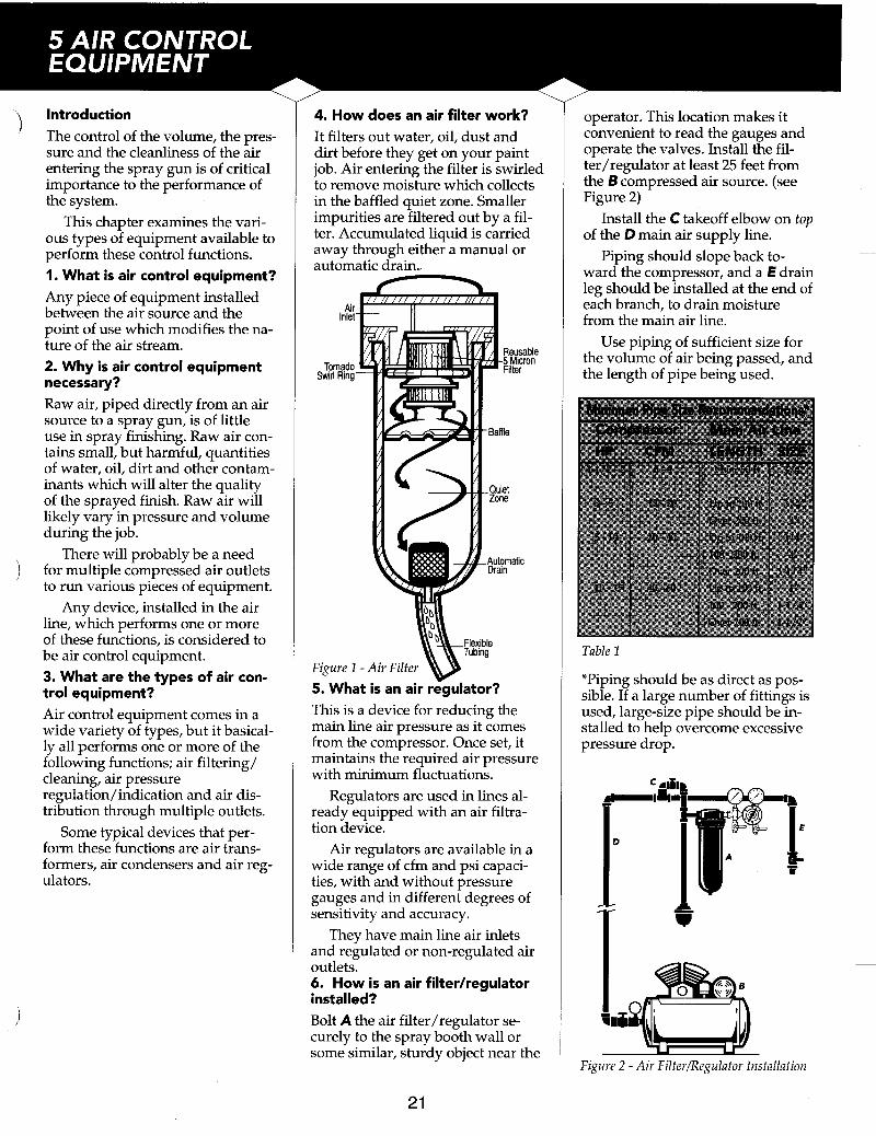
4. How does an air filter work? It filters out water, oil, dust and dirt before they get on your paint job. Air entering the filter is swirled to remove moisture which collects in the baffled quiet zone. Smaller impurities are filtered out by a fil- ter. Accumulated liquid is carried away through either a manual or automatic drain.. n
Air Inlet
Tornado Swirl Ring
Figure 1 5. What is an air rGulator? This is a device for reducing the main line air pressure as it comes from the compressor. Once set, it maintains the required air pressure with minimum fluctuations.
Regulators are used in lines al- ready equipped with an air filtra- tion device.
Air regulators are available in a wide range of cfm and psi capaci- ties, with and without pressure gauges and in different degrees of sensitivity and accuracy.
They have main line air inlets and regulated or non-regulated air outlets. 6. How is an air filterhegulator installed? Bolt A the air filter/regulator se- curely to the spray booth wall or some similar, sturdy object near the
operator. This location makes it convenient to read the gauges and operate the valves. Install the fil- ter/regulator at least 25 feet from the B compressed air source. (see Figure 2)
Install the C takeoff elbow on tup of the D main air supply line.
Piping should slope back to- ward the compressor, and a € drain leg should be installed at the end of each branch, to drain moisture from the main air line.
Use piping of sufficient size for the volume of air being passed, and the length of pipe being used.
-~
Table 1
*Piping should be as direct as pos- sible. If a large number of fittings is used, large-size pipe should be in- stalled to help overcome excessive pressure drop.
lli
21

7. How often should the filterhegulator be drained of ac- cumulated moisture and dirt? It depends largely on the level of system use and the amount of hu- midity in the air.
For average use, once-a-day drainage is probably sufficient.
For heavily-used systems, or in high humidity, drainage should oc- cur several times daily.
Some units drain automatically when moisture reaches a predeter- mined level. 8. What steps should be taken if moisture passes through the filterhegulator? Since moisture in the spray gun at- omization air will ruin a paint job, it must be removed from the air supply.
When the compressed air tem- perature is above its dew point temperature, oil and water vapor will not condense out into solid particles.
a) Drain transformer, air receiver and air line of accumulated mois- ture. b) Be sure the transformer is locat- ed at least 25 feet from the air source. c) Main air line should not run ad- jacent to steam or hot water piping. d) Compressor air intake should not be located near steam outlets or other moisture-producing areas. e) Outlet on the air receiver should be near the top of the tank. f) Check for damaged cylinder head or leaking head gasket, if the air compressor is water cooled. g) Intake air should be as cool as possible. 9. What causes excessive pres- sure drop on the main line gauge of the filterhegulator? a) The compressor is too small to deliver the required air volume and pressure for all tools in use.
Check the following:
b) The compressor is not function- ing properly. c) There is leakage in the air line or fittings. d) Valves are partially opened. e) The air line, or piping system, is too small for the volume of air re- quired. Refer to Table 1, Page 21.
22

Introduction 'ispray finishing creates a certain
amount of overspray, hazardous vapors and toxic fumes. This is true, even under ideal conditions, and there is no way to avoid it en- tirely.
Anyone near a spray finishing operation should use some type of respirator, or breathing apparatus. This chapter covers various types of equipment for this use. 1. What is a respirator? A respirator is a mask which is worn over the mouth and nose to prevent the inhalation of overspray fumes and vapor. 2. Why is a respirator necessary? For two reasons:
First ... some type of respiratory protection is required by OSHA/ NIOSH regulations.
Second ... even if it wasn't a re- quirement, common sense tells you that inhaling overspray is not
Overspray contains toxic parti- cles of paint pigments, harmful dust and, in some cases, vapor fumes which can be harmful to your health.
Depending on design, a respira- tor can remove some, or all, of these dangerous elements from the air around a spray finishing opera- tor. 3. What types of respirators are used by spray finishing operators? There are four primary types; the air-supplied respirator, the or- ganic vapor respirator, the dust res- pirator and the hood respirator. 4. What is an air-supplied respirator? This type is similar in concept to the hood respirator. It operates from an external supply of filtered air. (see Figure 1)
It covers the nose and mouth on- ly, not providing the degree of pro- !tection against splashes, etc. that 'the hood respirator would provide.
Figure 2 - Air Supplied Respiratorw 5. What is an organic vapor respirator and where is it used? This type of respirator, which cov- ers the nose and mouth, (see Figure 2) is equipped with a replacement cartridge that removes the organic vapors by chemical absorption.
Some are designed with a pre- filter to remove solid particles from the air before it passes through the chemical cartridge.
usually used in finishing opera- tions with standard materials.
The organic vapor respirator is
Figure 2 - Organic Vapor Respirator 6. What is a dust respirator and where is it used? Dust respirators are sometimes used in spray finishing but, in most applications, they are unsatisfacto- ry. (see Figure 3)
These respirators are equipped with cartridges that remove only solid particles from the air. They have no ability to remove vapors.
They are effective, however, in preliminary operations such as sanding, grinding and buffing.
Figure 3 - Dust Respirator 7. What is a hood respirator and where is it used? A hood respirator covers the entire head and neck area. It supplies the wearer with clean, dry air via a low pressure connection to the filtered air supply. It protects the wearer from heavy concentrations of va- por, fumes, dust and dirt that might prove harmful to respiratory organs, eyes, ears and exposed skin.
This style is used where other types of respirators are impractical, and do not provide sufficient pro- tection.
Figure 4 - Hood Respirator
23

Introduction All air tools, spray guns, sanders, etc., must be supplied with air which is elevated to the correct pressure and is delivered in suffi- cient volume. The air compressor compresses air for use in this equipment and is a major compo- nent of a spray painting system. This chapter will examine the vari- ous types available.
Compressed air is measured on the basis of the volume supplied per unit of time (cubic feet per minute, or cfm) at a given pressure per square inch (psi), referred to as delivery.
Displacement is the output of air by a compressor at zero pressure, or free air delivery. 1. What is an air compressor? An air compressor is a machine de- signed to raise the pressure of air from normal atmospheric pressure to some higher pressure, as mea- sured in pounds per square inch (psi). While normal atmospheric pressure is about 14.7 pounds per square inch, a compressor will typ- ically deliver air at pressures up to 200 psi.
When selecting a compressor, a handy rule-of-thumb is:
The cubic feet per minute deliv- ered by an electrically-pow-
ered air compressor is 4 times the motor’s horse power rat-
ing. (CFM=4xHP)
2. What types of compressors are most common in spray finish- ing operations? There are two common types; the piston-type design and the di- aphragm-type design.
Because most commercial spray finishing operations consume large quantities of compressed air at rela- tively high pressures, the piston- type compressor is the more com- monly used. 3. How does a piston-type compressor work? This design elevates air pressure through the action of a reciprocat- ing piston. As the piston moves
24
down, air is drawn in through an intake valve. As the piston travels upward, that air is compressed. Then, the now-compressed air is discharged through an exhaust valve into the air tank or regulator.
Piston type compressors are available with single or multiple cylinders in one or two-stage mod- els, depending on the volume and pressure required.
Figure 1 - Piston Type Air Compressor 4. How does a diaphragm-type compressor work? This design, which is usually quite small in volume and pressure out- put, develops pressure through the back and forth action of a flexible disk. 5. What is a single stage compressor? This is a piston-type compressor with one or more cylinders, in which air is drawn from the atmos- phere and compressed to its final pressure with a single stroke.
All pistons are the same size, and they can produce up to 100 psi. 6. Where are single stage com- pressors used? The application of this compressor is usually limited to a maximum pressure of 100 psi. It can be used above 100 psi, but above this pres- sure, two stage compressors are more efficient. 7. What is a two-stage compressor? A compressor with two or more cylinders of unequal size in which
air is compressed in two separate steps.
The first (the largest) cylinder compresses the air to an intermedi-
a connecting tube called an inter- cooler.
From there, the intermediate pressurized air enters the smaller cylinder, is compressed even more and is delivered to a storage tank or to the main air line.
Two stage compressors can de- liver air to over 100 psi.
They are normally found in op- erations requiring compressed air of 100 psi or greater. 8. What are the benefits of two stage compressors? Two stage compressors are usually more efficient. They run cooler and deliver more air for the power con- sumed, particularly in the over-100 psi pressure range. 9. Is there anything else to know about air compressors? Because this book mainly focuses on spray guns, it provides only ba- sic coverage of air compressors and how they operate.
There is much more to know: How to select the proper equip-
ment in terms of size, delivery, etc. Compressors may be portable or
stationary. There are different models to
meet a variety of needs. There are features to perform
specialized tasks, such as automatic unloaders, automatic pressure switches, motor starters and cen- trifugal pressure release devices.
And ... there is new equipment being designed and manufactured
If you have further questions, or
--- ate pressure. It then exhausts it into -
__
-
as you read this. -
need a specific catalog of air com- pressors, air dryers, accessories or service parts, please write or call: -
DeVilbiss Air Compressor Products P.O. Box 5800 Barrie, Ontario L4M 6K3 i
(705) 728-5657

Introduction
keeping it out of the air and off oth- er objects is an important consider- ation in a spray finishing operation. This chapter looks at the primary method of controlling overspray in the spray booth. It discusses vari- ous types of booths and details pe- riodic maintenance. 1. What is a spray booth? A compartment, room or enclosure of fireproof construction; built to confine and exhaust overspray and fumes from spray finishing.
There are various models avail- able, designed for particular spray applications.
Consult the National Fire Pro- tection Assdciation (NFPA) pam- phlet #33 and the O.S.H.A. require- ments for construction specifica- tions. 2. What are the benefits of a spray booth? A well-designed and maintained bpray booth provides important advantages:
tion from other shop activities, making the spraying, as well as the other operations, cleaner and safer.
It reduces fire and health haz- ards by containing the overspray.
It provides an area which con- tains residue, making it easier to keep clean. It also keeps both the operator and the object being sprayed cleaner.
In a booth equipped with ade- quate and approved lighting, it provides better control of the finish quality. 3. What types of spray booths are there? There are two; the dry filter type and the waterwash type. 4. What is a dry filter type spray booth? This booth draws overspray-conta- minated air through replaceable fil- lers and vents the filtered air to the 'outside.
'Containing the overspray and
It separates the spraying opera-
It is the most common type of booth for most industrial applica- tions.
It is used for spraying low-vol- ume, slower-drying materials, and is not affected by color changes.
Material volume should not ex- ceed 10-15 gallons per day.
t
Figure 1 - Dry Filter Type Booth 5. What is a waterwash type booth? A waterwash booth actually wash- es the overspray-contaminated air with a cascade of water, and traps the paint solids. Fewer paint parti- cles reach the outside atmosphere to harm the environment.
used when spraying more than 15 gallons of material a day.
Waterwash booths are generally
Figure 2 - Waterwash Type Spray Booth
25
6. What is an exhaust fan? A typical exhaust fan consists of a motor, a multiple blade fan, pulleys and belts. It removes overspray from the spray booth area.
carefully designed to prevent over- spray from coming into contact with the drive mechanism.
Blades are made of non-spark- ing metal, and they move the maxi- mum volume of air-per-horsepow- er against resistance such as ex- haust stacks, filters, etc. (See NFPA pamphlet #33.)
Contemporary exhaust fans are
Figure 3 - Exhaust fan 7. What is air velocity? Air velocity in a finishing operation is the term used to describe the speed of air moving through the empty spray booth. 8. What effect has air velocity on spray booth efficiency? Air must move through the booth with sufficient velocity to carry away overspray.
Too low a velocity causes poor, even potentially dangerous work- ing conditions, especially when the material contains toxic elements. It also increases maintenance costs.
Too high a velocity wastes pow- er and the energy required to heat make-up air.

9. What is a manometer? It is a draft gauge which indicates when paint arrestor filters or intake filters are overloaded.
Some states and local codes re- quire a manometer gauge on each bank of filters to comply with OSHA regulations.
Figure 4 - Manometer I O . What does an air replacement unit do? The volume of air exhausted from a spray booth is often equal to three or more complete air changes per hour.
Under such conditions, the tem- perature may become irregular and uncomfortable. Excessive dust may become a problem.
To prevent these conditions, suf- ficient ”make-up” air must be in- troduced to compensate for the ex- hausted air.
The air replacement unit auto- matically supplies this ”makeup” air -both filtered and heated - to eliminate the problems of air defi- ciency.
Figure 5 -Air Replacement Unit
11. What routine maintenance does a dry type spray booth require? (a) The continuous flow of air through the booth eventually loads the filters with dirt and overspray. Periodically, inspect and replace them with multistage filters, de- signed for spray booth use. Single- stage furnace filters will not do the job. (b) Monitor the manometer read- ings daily, and know what a nor- mal reading should be. (c) Keep the booth free of dirt and overspray. Floors and walls should be wiped down after every job. Pick up scrap, newspapers, rags, etc. (d) Coat the inside of the booth with a shippable, spray-on cover- ing. When the overspray on it be- comes too thick, strip and recoat. (e) Periodically check the lighting inside the booth, and replace weak or burned out bulbs. Improper lighting can cause the operator to apply a poor finish. 12. What routine maintenance does a waterwash type booth require? (a) Compounding of the water in this type unit is essential. Employ only booth treatment chemicals in accordance with suppliers’ recom- mendations. The ph of the water should be between 8 and 9. (b) Maintain the water level at the proper setting per manufacturers’ specifications. (c) Check the tank for paint buildup on the bottom, check the pump strainer to keep it clean and clear, check the air washer chamber and the nozzles in the header pipe. If the nozzles are plugged, the overspray will encroach on the wash baffle section, fan and stack. (d) Periodically check the float valve for proper operation. Flood the sheet to be sure there is a uni- form flow over the entire surface. (e) Keep the booth interior and ex- haust stack free from overspray and dirt accumulation.
13. What checks can be used to assure good results from a spray booth? (a) Keep the interior of the booth clean. (b) Maintain and replace intake and exhaust filters when necessary. (c) Caulk all seams and cracks where dirt might enter. (d) Maintain and clean all equip- ment used in the booth. (e) Keep operators’ clothing clean and lint-free. (f) Perform routine maintenance above on a scheduled basis.
For further information on spray booths, air replacement units or ac- cessories, please write or call:
DeVilbiss Spray Booth Products -
520-A Wharton Circle Atlanta, GA 30336 (404) 696-4988
26

DeVilbiss ... sales and service available through a nationwide network of distributors. I U.S. Offices Canadian Office CALIFORNIA Main Location DISTRIBUTED BY: Industrial Distribution Center P.O. Box 3000 12878 E. Florence Avenue Barrie, Ontario L4h4 4V6 Santa Fe Springs, CA 90670 Canada (310) 944-1111 (705) 728-5501 FAX: (310) 944-5786 FAX: 728-4974
OHIO Headquarters 1724 Indian Wood Circle Maumee, OH 43537 (419) 891-8200 FAX: (419) 891-8205
For Industrial Technical Assistance, call (800) DEV-4448 (USA only). For Automotive Refinish Technical Assistance, call (800) 445-3988 (USA only). Form I-239B 2/93 Litho USA 01995 ITW DeVilbiss - All rights reserved. Models and specificatmns subject to change