
The 5G K-Simulator5gopenplatform.org/se2/5G K_Sim_WhitePaper.pdfThe 5G K-Simulator: Flexible, Open,...
23
The 5G K-Simulator: Flexible, Open, Modular (FOM) Design White Paper January, 2019 5G Wireless Innovative Systems Engineering (WISE) Research Center
Transcript of The 5G K-Simulator5gopenplatform.org/se2/5G K_Sim_WhitePaper.pdfThe 5G K-Simulator: Flexible, Open,...

The 5G K-Simulator:Flexible, Open, Modular (FOM) Design
White Paper
January, 2019
5G Wireless Innovative Systems Engineering (WISE) Research Center
The 5G K-Simulator: Flexible, Open, Modular (FOM) Design White Paper
Contents
1 Introduction 2
2 The 5G K-Simulator: Flexible, Open, Modular (FOM) Design 4
2.1 Structure . . . . . . . . . . . . . . . . . . . . . . . . . . . . . . . . . . . . . . . . . . . . . . . . . . . . . . 4
2.2 Design Philosophy: Flexible, Open, and Modular (FOM) . . . . . . . . . . . . . . . . . . . . . . . . . 4
3 The 5G K-SimLink: Link-Level Simulator 6
3.1 Block diagram . . . . . . . . . . . . . . . . . . . . . . . . . . . . . . . . . . . . . . . . . . . . . . . . . . 6
3.2 Structure . . . . . . . . . . . . . . . . . . . . . . . . . . . . . . . . . . . . . . . . . . . . . . . . . . . . . . 6
3.3 Features . . . . . . . . . . . . . . . . . . . . . . . . . . . . . . . . . . . . . . . . . . . . . . . . . . . . . . 6
4 The 5G K-SimSys: System Level Simulator 8
4.1 Structure . . . . . . . . . . . . . . . . . . . . . . . . . . . . . . . . . . . . . . . . . . . . . . . . . . . . . . 8
4.2 Simulation procedure . . . . . . . . . . . . . . . . . . . . . . . . . . . . . . . . . . . . . . . . . . . . . . 8
4.3 Implementation with 5G K-SimSys . . . . . . . . . . . . . . . . . . . . . . . . . . . . . . . . . . . . . . 9
4.4 Features . . . . . . . . . . . . . . . . . . . . . . . . . . . . . . . . . . . . . . . . . . . . . . . . . . . . . . 10
5 The 5G K-SimNet: Network Simulator 11
5.1 Block diagram . . . . . . . . . . . . . . . . . . . . . . . . . . . . . . . . . . . . . . . . . . . . . . . . . . 11
5.2 Multi-Connectivity . . . . . . . . . . . . . . . . . . . . . . . . . . . . . . . . . . . . . . . . . . . . . . . . 11
5.3 5G Core: SDN/NFV . . . . . . . . . . . . . . . . . . . . . . . . . . . . . . . . . . . . . . . . . . . . . . . . 12
5.4 Features . . . . . . . . . . . . . . . . . . . . . . . . . . . . . . . . . . . . . . . . . . . . . . . . . . . . . . 13
5.5 Comparison . . . . . . . . . . . . . . . . . . . . . . . . . . . . . . . . . . . . . . . . . . . . . . . . . . . . 14
6 Additional features on 5G K-Simulator 15
6.1 5G K-LinktoSys: Link-to-System Mapping . . . . . . . . . . . . . . . . . . . . . . . . . . . . . . . . . . 15
6.2 Hard-interworking between SLS and NS . . . . . . . . . . . . . . . . . . . . . . . . . . . . . . . . . . . 17
7 5G K-SimPlatform 19
7.1 Web platform . . . . . . . . . . . . . . . . . . . . . . . . . . . . . . . . . . . . . . . . . . . . . . . . . . . 19
7.2 Cloud platform . . . . . . . . . . . . . . . . . . . . . . . . . . . . . . . . . . . . . . . . . . . . . . . . . . 20
8 Conclusion 21
1

The 5G K-Simulator: Flexible, Open, Modular (FOM) Design White Paper
1 Introduction
With a new paradigm beyond the current communication systems for high data rate, reduced latency and massive
connectivity, the fifth-generation (5G) systems have been evolved to improve the long-term evolution (LTE) and
LTE-Advanced systems. The International Telecommunication Union (ITU) recommends three usage scenarios;
enhanced Mobile Broadband (eMBB), ultra-Reliable and Low Latency Communications (uRLLC) and massive
Machine Type Communications (mMTC), and eight key performance indicators (KPIs) for 5G systems. Based on
these scenarios and KPIs, the Third Generation Partnership Project (3GPP) will complete the first (Release 15)
and second (Release 16) phase of the 5G specification consecutively by March 2020, as candidates for IMT-2020
technology.
Figure 1: Three usage scenarios
Figure 2: Eight KPIs
The key technologies for 5G systems have been widely studied from many universities, research institutes and
companies, but they solely rely on their own simulation tools to qualify their technical skills for 5G systems. During
the development of the fourth-generation (4G) systems (i.e., LTE and LTE-Advanced), a number of open-source
simulators such as Vienna LTE-A from Technische Universitat Wein (TUW), NYUSIM from New York University,
and LTE-Sim from Politecnico di Bari (POLIBA) were provided to help researchers develop and test their 4G
technologies. However, there are very few open-source simulators for 5G systems, and it is expected that the time
and cost for the development of 5G simulators increase significantly compared to those for 4G systems due to
complex features and strict requirements of 5G systems. Currently, NYUSIM and Vienna LTE-A are being extended
to provide 5G features. MathWorks offers 5G Toolbox, but with a purchase of LTE Toolbox. However, they are
not sufficient to cover the comprehensive features of 5G systems. Hence, the need for universal 5G simulators is
growing.
The 5G K-Simulator, which is a standard-compliant, open-source and comprehensive simulator for 5G systems,
has been developed to follow the 3GPP roadmap for 5G systems. Its current version is based on 3GPP Release 15,
and will be updated to reflect 3GPP Release 16 when it is completed. In addition, it is open for non-commercial
usage, so users can download source codes of 5G K-Simulator from the webpage along with user manuals for user
convenience. Since 5G K-Simulator provides link level, system level and network simulators, each simulator can be
utilized to test technologies for physical (PHY), medium access control (MAC) and transport layer independently. In
2

The 5G K-Simulator: Flexible, Open, Modular (FOM) Design White Paper
Figure 3: Comparision of 5G simulators
addition, the mapping modules that connect link level and system level simulators allows an accurate system level
simulation. Furthermore, we have developed a web-based platform for 5G K-Simulator, called 5G K-SimPlatform,
to provide an on-line cloud-computing environment to run the simulator. The 5G K-SimPlatform is composed of a
web-based platform and a cloud platform, where the web-based platform provides graphic user interface (GUI)
implemented on computing environments supported by the cloud platform.
This paper is intended as an introduction for researchers and students to use the 5G K-Simulator and 5G
K-SimPlatform. In the rest of the paper, we will give the general description and structure of the 5G K-Simulator.
3

The 5G K-Simulator: Flexible, Open, Modular (FOM) Design White Paper
2 The 5G K-Simulator: Flexible, Open, Modular (FOM) Design
2.1 Structure
The 5G K-Simulator represents a hierarchical architecture, where it is composed of three layers and a mapping
module. Each layer corresponds to 5G K-SimLink, 5G K-SimSys and 5G K-SimNet, respectively.
The 5G K-SimLink is a link-level simulator (LLS) that focuses on a point-to-point wireless link between a base
station (BS) and a user equipment (UE). The physical (PHY) layer technologies, such as channel coding, waveform,
modulation and so on, can be evaluated. The simulator provides both uplink and downlink communication
environments.
The 5G K-SimSys is a system level simulator (SLS) and designed to analyze the performance of the medium
access control (MAC) layer technologies, such as scheduling and radio resource management. The 5G K-SimLink
considers a single-user single-cell scenario, whereas the 5G K-SimSys simulates a multi-user multi-cell environment
by taking interference between adjacent users into account. The link-to-system mapping between 5G K-SimLink
and 5G K-SimSys, denoted as 5G K-LinktoSys, can be utilized to evaluate the system level performance more
accurately by reflecting the characteristic of a point-to-point link. To be specific, bit/block error rate (BER/BLER)
of a point-to-point link obtained by 5G K-SimLink can be mapped into to a signal to noise ratio (SNR) by the 5G
K-LinktoSys, and the corresponding effective SNR can be used in 5G K-SimSys to evaluate multi-user multicell
environments.
The 5G K-SimNet is a network simulator (NS) to analyze end-to-end performances. It models radio link control
(RLC), radio resource control (RRC) and packet data convergence protocol (PDCP), constructs a core network,
and evaluates the transport layer protocols. In addition, it provides a guideline for cross-layering research between
5G K-SimSys and 5G K-SimNet by mapping statistical results from 5G K-SimSys to transport layer protocol (e.g.,
transmission control protocol (TCP)) in 5G K-SimNet.
Figure 4: Structure of 5G K-Simulator
2.2 Design Philosophy: Flexible, Open, and Modular (FOM)
The 5G K-Simulator is an open-source simulator available for non-commercial usage. The user manuals are offered
for each level of simulators to help users’ understanding, and explain how to configure parameters and the
4

The 5G K-Simulator: Flexible, Open, Modular (FOM) Design White Paper
procedure of simulations from simulator installation to performance evaluation. In addition, typical examples are
included to help users understand the simulator.
The 5G K-Simulator provides a high flexibility to test various simulation configuration for users’ purpose. In
addition, key functions and techniques for 5G systems have been developed in modules and blocks. Flexibility
and modularity enable simulations to be performed with a particular set of blocks of interest. Furthermore, users
can add or replace the module for target simulations. Due to modular structure, the performance evaluation
or debugging process can be conducted sequentially by inspecting an individual module, hence the accuracy of
simulation results can be achieved by module-level verification.
Figure 5: FOM structure
5

The 5G K-Simulator: Flexible, Open, Modular (FOM) Design White Paper
3 The 5G K-SimLink: Link-Level Simulator
Figure 6: Link level simulator
5G K-SimLink is a link level simulator for wireless communication system
based on 3GPP specifications. The purposes of the 5G K-SimLink are 1) to
evaluate the average performance of the physical (PHY) layer transceiver
architecture and 2) to provide effective SNR results to 5G K-SimSys for
modeling PHY layer functions. 5G K-SimLink supports SU-SISO and SU-
MIMO simulations.
3.1 Block diagram
5G K-SimLink consists of 4 classes: BS, 5G Channel, UE, and Parameter class as shown in Fig. 7. The blocks
which contain key features of 5G are highlighted. Since 5G K-SimLink is based on object-oriented programming
(OOP), it is easy for users not only to use as it is but also expand/replace blocks or functions therein through FOM
(Flexible/Open/Modular) structure.
Figure 7: 5G K-SimLink: Block diagram
3.2 Structure
Figure 8: 5G K-SimLink: Structure
.5cm5G K-SimLink is configured hierarchically. It
consists of main simulation files and 6 categories
(BS, Channel, Parameters, UE classes, Coding, and
Results) according to the functionality. In each cat-
egory, there are function modules related to the cor-
responding category.
3.3 Features
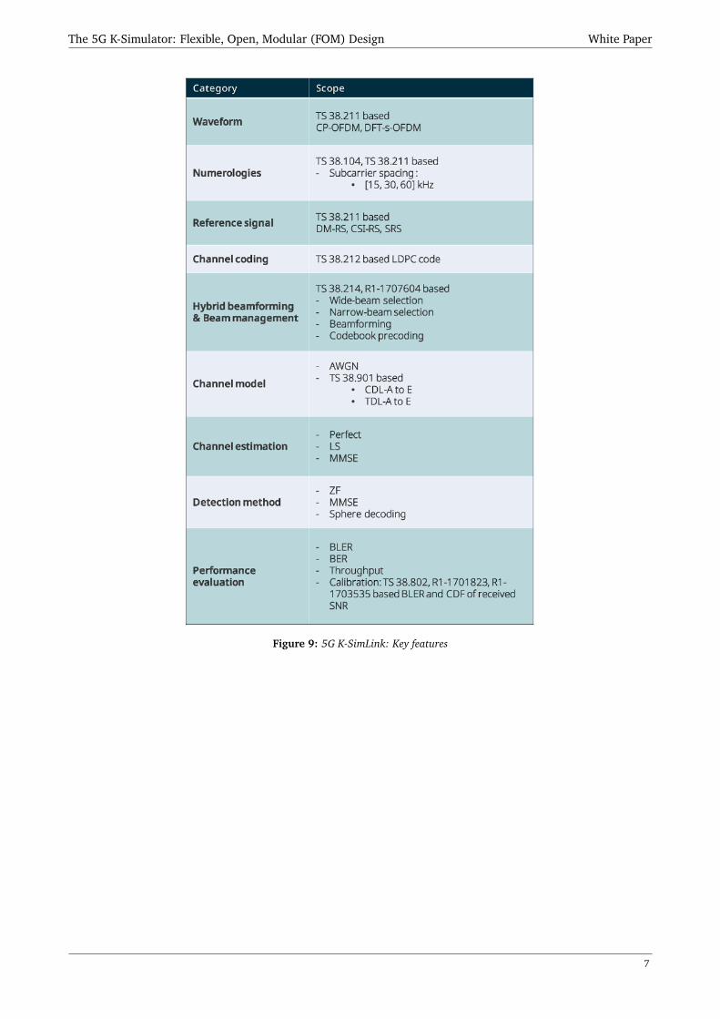
Key features of 5G K-SimLink are summarized in Fig. 9.
6
The 5G K-Simulator: Flexible, Open, Modular (FOM) Design White Paper
Figure 9: 5G K-SimLink: Key features
7

The 5G K-Simulator: Flexible, Open, Modular (FOM) Design White Paper
4 The 5G K-SimSys: System Level Simulator
Figure 10: System level simulator
cmThe 5G K-SimSys is a system level simulator for mobile telecommuni-
cation system with multi-cell and multi-users scenarios. Under the varying
other-cell interference and received signal strength in mobile stations, MAC-
layer functionalities for the radio resource management in line with mobile
links are simulated for evaluating the system level performance, includ-
ing the average system throughput, spectral efficiency, latency, and other
related performance metrics. It also imports the 5G K-SimLink for PHY
abstraction to support link-to-system mapping (i.e., 5G K-LinktoSys).
4.1 Structure
The 5G K-SimSys consists of 15 modules, each of which is classified by its own object and purpose. The object
is identified by three different classes: Sim, BS, or MS. Each class is identified by its own purpose, including
simulation top, network configuration, channel model, radio resource management, and link performance,
implementing the different functionality in the simulator. Thanks to the well-defined & flexible structure, users
can add, modify, and expand the details of individual module to be suited to the different system and service
scenarios. Simulation top is the object that manages the entire flow of the simulation, thereby improving the
readability of the entire simulator.
Figure 11: 5G K-SimSys: Structure
4.2 Simulation procedure
The 5G-K SimSys is conforming to the standardized evaluation methodologies for IMT-2020 in ITU-R Working
Party 5D. Its procedure include initialization of input parameters, placemen t of BSs and MSs, calculation of
long-term channel, cell association, calculation of short-term channel, feedback from MSs, scheduling, and
8
The 5G K-Simulator: Flexible, Open, Modular (FOM) Design White Paper
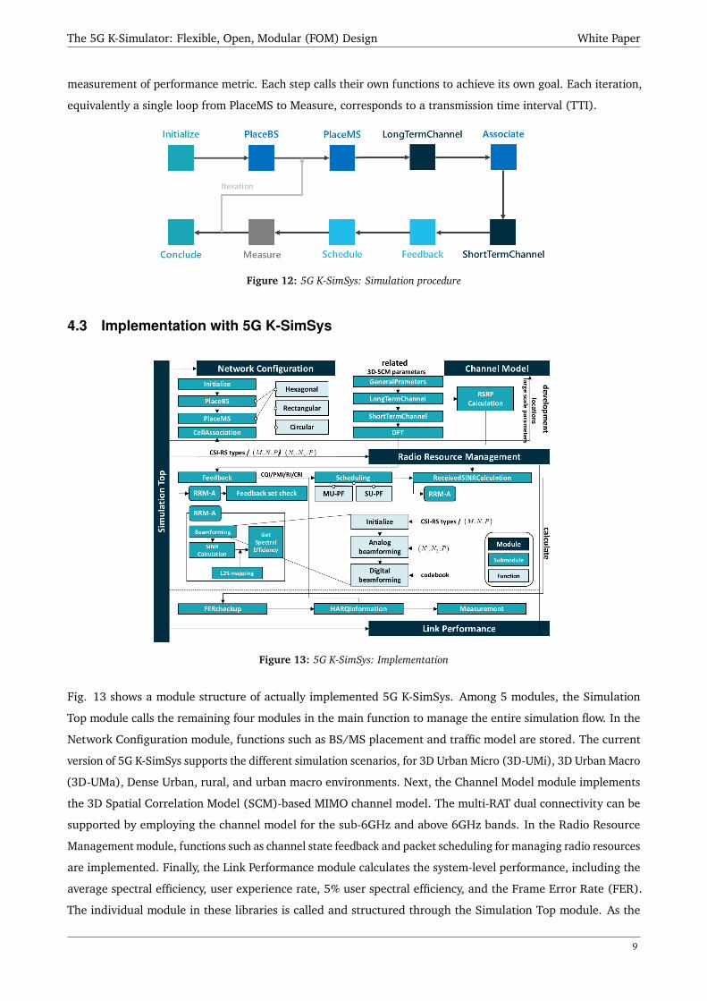
measurement of performance metric. Each step calls their own functions to achieve its own goal. Each iteration,
equivalently a single loop from PlaceMS to Measure, corresponds to a transmission time interval (TTI).
Figure 12: 5G K-SimSys: Simulation procedure
4.3 Implementation with 5G K-SimSys
Figure 13: 5G K-SimSys: Implementation
Fig. 13 shows a module structure of actually implemented 5G K-SimSys. Among 5 modules, the Simulation
Top module calls the remaining four modules in the main function to manage the entire simulation flow. In the
Network Configuration module, functions such as BS/MS placement and traffic model are stored. The current
version of 5G K-SimSys supports the different simulation scenarios, for 3D Urban Micro (3D-UMi), 3D Urban Macro
(3D-UMa), Dense Urban, rural, and urban macro environments. Next, the Channel Model module implements
the 3D Spatial Correlation Model (SCM)-based MIMO channel model. The multi-RAT dual connectivity can be
supported by employing the channel model for the sub-6GHz and above 6GHz bands. In the Radio Resource
Management module, functions such as channel state feedback and packet scheduling for managing radio resources
are implemented. Finally, the Link Performance module calculates the system-level performance, including the
average spectral efficiency, user experience rate, 5% user spectral efficiency, and the Frame Error Rate (FER).
The individual module in these libraries is called and structured through the Simulation Top module. As the
9
The 5G K-Simulator: Flexible, Open, Modular (FOM) Design White Paper
detailed implementation is hidden hierarchically deep in the submodules, it can be tracked down in the process
only by those who need to modify their functions whenever necessary. Then, the readability of the simulator is
improved and any form of the simulator can be flexibly built up by reconfiguring the main function by the stored
functions in the modules. As use cases of 5G K-SimSys, we have implemented the simulators for the 5G eMBB and
uRLLC services to evaluate the average spectral efficiency and the uRLLC capacity in urban macro environment,
respectively.
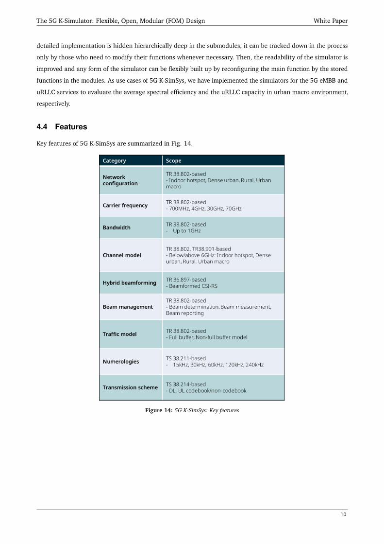
4.4 Features
Key features of 5G K-SimSys are summarized in Fig. 14.
Figure 14: 5G K-SimSys: Key features
10

The 5G K-Simulator: Flexible, Open, Modular (FOM) Design White Paper
5 The 5G K-SimNet: Network Simulator
The 5G K-SimNet is a network simulator for wireless communication system based on 3GPP Rel.15. The purpose
of the 5G K-SimNet is to evaluate the average end to end performance of the network. The 5G K-SimNet is being
expanded from NS-3, and 5G K-SimNet supports LTE-NR (New Radio) dual connectivity (DC) and SDN/NFV
(Software-Defined Network/Network Function Virtualization) modules for end to end performance. LTE-NR dual
connectivity is one of 5G’s main features to compensate for the instability of NR link. SDN/NFV module is an
essential function for the network slicing technology. The green modules are implemented in 5G K-SimNet for
new 5G features.
Figure 15: 5G K-SimNet: Structure
5.1 Block diagram
Target topology for 5G K-SimNet is represented in Fig. 16: connected LTE-NR DC and SDN/NFV modules. UE
includes both LTE and NR protocols. Packets are shared between the eNB and the gNB via the X2 interface. To
realize SDN/NFV, 5G-K SimNet implements the radio access/core network with multiple SDN switches under
SDN/NFV module. Currently, the core network is implemented based on 4G EPC, but 5G core network will be
available on Feb. 2019. The 5G K-SimNet is the first open-source network simulator to test key features of 5G
network, and well-structured to use, modify and expand by users.
5.2 Multi-Connectivity
The protocol model for multi-connectivity includes the LTE radio protocol for connecting control-plane (C-plane)
and the dual 5G NR protocol for reliable user-plane (U-plane) connection. These entities reside entirely within a
UE and an evolved node B (eNB)/gNB. The model, which is based on multi-connectivity, provides the cooperating
network architecture between 4G LTE and 5G NR in the transition period from 4G to 5G. We develop the multi-RAT
protocol stack, the packet sequencing, packet reordering, and simple traffic split algorithm by exploiting the
conventional LTE model developed by LENA project, and the mmWave radio model developed by NYU WIRELESS
and the University of Padova. Furthermore, the procedure for SN handover is developed. Using this model, we
11

The 5G K-Simulator: Flexible, Open, Modular (FOM) Design White Paper
Figure 16: 5G K-SimNet: Block diagram
can evaluate the performance of the protocol for multi-connectivity. For example, the following features can be
evaluated: traffic split/routing algorithm, RLC queue management scheme, MAC scheduling algorithm, mobility
supporting functions and so on. These algorithms and schemes can be modified or developed by users. The
simulation results are as follows: (i) end-to-end performance such as transmission control protocol (TCP) and user
datagram protocol (UDP) throughput, round trip time (RTT), and congestion window size, (ii) specific protocol
performance such as PDCP packet drop rate, RLC queue size/delay, PHY signal-to-interference plus-noise ratio
(SINR) values, and so forth.
5.3 5G Core: SDN/NFV
It is expected that 5G core utilizes NFV and SDN. More specifically, in a 4G System, the EPC network functions
are implemented on black-box hardwares. However, in the 5G System, network functions become softwarized, so
they are not implemented on black-boxes. 5G core is placed on an NFV platform, and each network function is
installed and run on virtual machines (VMs), instead of black-boxes. These VMs can have connectivity with each
other by utilizing SDN, and the SDN controller monitors or controls network traffic among them. It can be also
utilized on balancing traffic between core networks and radio access networks. These changes make network
operators be able to manage their networks more easily and flexibly. For example, if a network function running
on a VM becomes overloaded due to too high computational workload, a network operator can run another VM
through an NFV platform. Then it can migrate some part of workloads from the original network function to
a newly booted one. However, if we introduce the NFV/SDN techniques, additional delays could be caused by
provisioning and migrating VM. It might result additional delays on end-to-end communication. Our SDN/NFV
components include the functions which measure these side effects of introducing NFV and SDN to the 5G System.
Virtualization side effects mean additional delay components, which do not exist on non-virtualized core networks.
Additional delays come from a VNF topology which is decided by network operators. For example, scaling delay
can be caused by introducing NFV technique to 5G core network. With NFV, each 5G core network function could
be run on a VM as VNF. If the VNF has 8 central processing units (CPUs) but its workload exceeds it, NFV platform
autoscales the VNF. In this case, the VNF is scaled-out, so two (or more) VNFs might be operated. This auto-scaling
12

The 5G K-Simulator: Flexible, Open, Modular (FOM) Design White Paper
takes some delays such as provisioning or migration delays, so user might experience longer latency due to NFV
technique, temporally. Other side effects can be evaluated with SDN. With SDN, the network operator can control
network traffic flowing through core networks. Traffic re-routing or balancing operation can be example cases.
The simulation results are end-to-end performances including VM delay, network delay, and so on. User can
control traffic which flows through SDN networks, and verify it by investigating SDN switch throughput per port.
The simulator calculates such side effects by following simulation process of Fig. 17. For running a simulation,
users should set their own simulation topology and parameters related to SDN/NFV operation. Once they (user
codes) are provided to the simulator, the simulator runs virtualization modules and SDN modules. Virtualization
modules calculate virtualization-related delays such as scaling delay or provisioning delay. First, simulation nodes
are placed depending on the topology of user codes. Dynamic workloads (Workloads changes along the simulation
time) of core NFs, i.e., mobility management entity (MME) and packet data network/servinggateway (P/S-GW),
are generated by using static workloads of parameters of user codes. VNF delays are calculated after configuring
scaling thresholds, analyzing the topology and VNF policies. SDN modules also place simulation nodes first. They
configure OpenFlow switches and a controller. After then they run OpenFlow application such as QoS bandwidth
controller. The final simulation results come out by merging results of virtualization modules and SDN modules.
We are also implementing essential parts of 5G core for a downlink scenario: AMF, SMF, UPF. With such NFs,
control signals such as user equipment (UE) registration, deregistration or service requests are implemented
based on 3GPP specification. Control signal procedures of 5G System differ from those of LTE System. In case
of service requests, authentication procedures are followed after radio resource control (RRC) requests in LTE
system. However, in 5GS, RRC requests are followed after authentication procedures. It is a just representative
case, however, procedures of LTE and those 5GS show different points in details.
Figure 17: 5G K-SimNet: SDN/NFV simulation procdure
5.4 Features
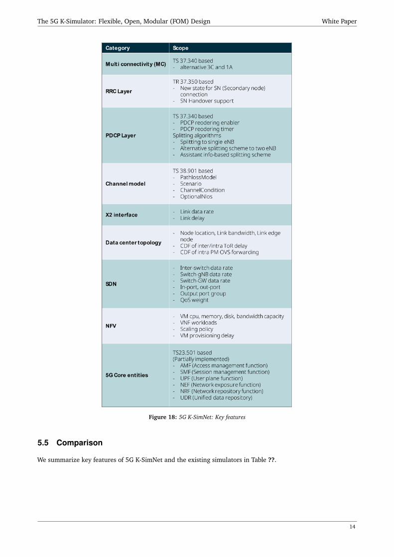
Key features of 5G K-SimNet are summarized in Fig. 18
13
The 5G K-Simulator: Flexible, Open, Modular (FOM) Design White Paper
Figure 18: 5G K-SimNet: Key features
5.5 Comparison
We summarize key features of 5G K-SimNet and the existing simulators in Table ??.
14

The 5G K-Simulator: Flexible, Open, Modular (FOM) Design White Paper
Table 1: Key features of 5G K-SimNet and existing simulators
LENA [lena] mmWave ns-3 [mezzavilla2018end] 5G K-SimNet
Developer Centre Tecnològic deTelecomunicacions de Catalunya (CTTC)
NYU WIRELESS,University of Padova
Seoul National University
Description LTE/EPC simulation tool mmWave cellular simulation tool 5G end-to-end network simulation toolCore network model Simple EPC model with one gateway and MME SDN/NFV, 5G core (AMF, SMF, UPF)
RRC model- System information (MIB, SIBs)- RRC connection Establishment- RRC connection reconfiguration
- Includes LENA RRC model- Secondary node addition forLTE-mmWave dual connectivity
- Includes mmWave ns-3 RRC model- Split bearer for LTE-mmWavemulti-connectivity
- Secondary node addition forLTE-mmWave multi-connectivity
- Secondary node handover
Radiomod
el
PDCP model
- PDCP headers defined by 3GPP- Transfer data for both U and C-plane- Maintain PDCP sequence numbers- Transfer sequence number status toneighbor eNB for handover
- Includes LENA PDCP model- Steer traffic from LTE PDCPto mmWave RLC
- Includes mmWave ns-3 PDCP model- Reordering for in-sequence delivery- Duplicate elimination- Timer based discard- Traffic management on split bearer· Traffic steering· Traffic splitting· Traffic duplication
RLC model
- Three RLC models defined by 3GPP· Transparent mode· Unacknowledge mode· Acknowledge mode
- Simplified model: full-buffer model
- Includes LENA RLC model- Expand RLC sequence spaceto handle huge amount ofretransmission
- Includes mmWave ns-3 RLC model- RLC buffer status measurement- RLC buffer status reporting to trafficmanagement function
PHY/MAC model - Frequency division duplex- Time division duplex- Flexible frame structure
- Same as mmWave ns-3
Channel model - Various models [ns3]- Adds channel model defined in3GPP TR 38.900 [38.900]
- Updates channel model defined in3GPP TR 38.901 [38.901]
Antenna model- Isotropic model- Cosine model- Parabolic model
- Uniform planar array(linear-polarized antenna)
- Analog beamforming [ns3channel]
- Uniform planar array(linear and cross polarized antenna)
- Analog beamforming [36.897](one-dimension full-connection model)
15

The 5G K-Simulator: Flexible, Open, Modular (FOM) Design White Paper
6 Additional features on 5G K-Simulator
6.1 5G K-LinktoSys: Link-to-System Mapping
The link-to-system (L2S) mapping method has two aims to map various SNRs over allocated resource elements
(REs) to one averaged SNR as well as to reduce system overload in SLS. The overall procedure of 5G K-LinktoSys
is shown in Fig. 19 where L2S mapping method basically receives raw data of γ1, ...,γNRE and BLER from the LLS
and then deliver two mapping parameters of (α1,α2) and 5G NR AWGN to the SLS. 5G K-LinktoSys is composed
of 4 modules such as M1: loading raw data, M2: AWGN curve, M3: Effective SNR (ESM), and M4: exponential
ESM (EESM) L2S mapping. The operation and function of each module are explained below.
Figure 19: Schematic of 5G NR L2S mapping
1. Module M1 : Loading raw data
M1 module reads the stored date (i.e., received SINR: γ1, ...,γNRE , BLER). The format of raw data is composed
of x rows and y columns for each CQI. The value of x is (the number of input SNRs the number of simulations
(Sims)), and the value of y is NRE+2. The number of allocated sub-carriers per slot is NRE. The first column
is a given input SNR, the last column is BLER, and the rest of columns mean γ1, · · · , γNRE . The data loading
is performed for AWGN channel and all fading channels, respectively.
2. Module M2 : AWGN curve
M2 module only applies to AWGN channel. It gets AWGN raw data from M1 module and makes AWGN
fitting curve for SNR versus BLER in the range of all CQIs. The AWGN fitting curve is generated from the
relation of (γ1, ...,γNRE ) and BLER. Generally, the fitting curve of BLER at γk is induced from an exponential
function or regression curve of machine learning.
3. Module M3 : Effective SNR
M3 module calculates an effective SNR applying α1 and α2 when a UE measures many received SNRs such
as γ1, ...,γNRE .
γe f f (α1,α2)=−α1ln(
1N
N∑k=1
exp(−γk
α2
)),
where α1 and α2 are determined after optimization in M4.
In a fact, SLS only measures {γ1, ...,γNRE } without decoding. To estimate error for a received TB, SLS
16

The 5G K-Simulator: Flexible, Open, Modular (FOM) Design White Paper
calculates an effective SNR using α1 and α2. The values of α1 and α2 are already reported to SLS through a
L2S mapping method.
4. Module M4 : EESM based L2S Mapping
M4 module finds optimal mapping parameters of α1 and α2 for a given CQI and a type of fading environment.
After performing M snapshots, we calculate mean square error (MSE) as follows:
MSE(α1,α2)= 1M
∑i=1
M[log10BLERi − log10BLERR
(γi
re f (α1,α2))]2
,
where M denotes the total number of simulated snapshots and BLERi denotes the BLER measured from
the ith post-processing SINR values. In addition, γie f f (α1,α2) is calculated at the ith snapshot, and BLERR
is the value of BLER on AWGN channel. Furthermore, BLERR(x) means that output BLER corresponding to
input x from AWGN fitting curve plotted in module M2.
To find optimal α∗1 and α∗
2 , we minimize MSE for all range of (α1,α2) as follows:
(α∗1 ,α∗
2 )= argmin(α1,α2)
MSE(α1,α2).
Since the BLERs vs SNR are varied depending on the modulation method, code block size and code rate, we
should find α∗1 and α∗
2 under the condition of all CQIs and all fading model.
Table 2: Optimal parameters (α∗1 ,α∗2 ) in 5G CDL-A SISO
CQI AdaGrad RMSPropα1 α2 MSE α1 α2 MSE
1 3.294 3.230 0.150 2.752 2.698 0.1492 1.874 1.880 0.357 2.163 2.170 0.3643 1.607 1.594 0.065 2.002 1.988 0.0614 1.184 1.175 0.159 1.162 1.154 0.1565 1.286 1.283 0.140 1.552 1.546 0.2066 1.359 1.359 0.055 1.360 0.360 0.0567 3.642 3.628 0.170 3.643 3.629 0.1708 3.256 3.228 0.171 3.937 3.911 0.1559 5.563 5.543 0.110 5.636 5.616 0.11010 16.259 16.204 0.075 16.262 16.208 0.07511 13.685 13.604 0.329 13.382 13.301 0.26812 17.988 18.079 0.778 17.547 17.632 0.72413 23.971 23.970 0.555 24.112 24.111 0.55814 29.306 29.205 0.210 29.306 29.204 0.21015 33.590 33.833 0.533 28.733 28.739 0.823
17
The 5G K-Simulator: Flexible, Open, Modular (FOM) Design White Paper
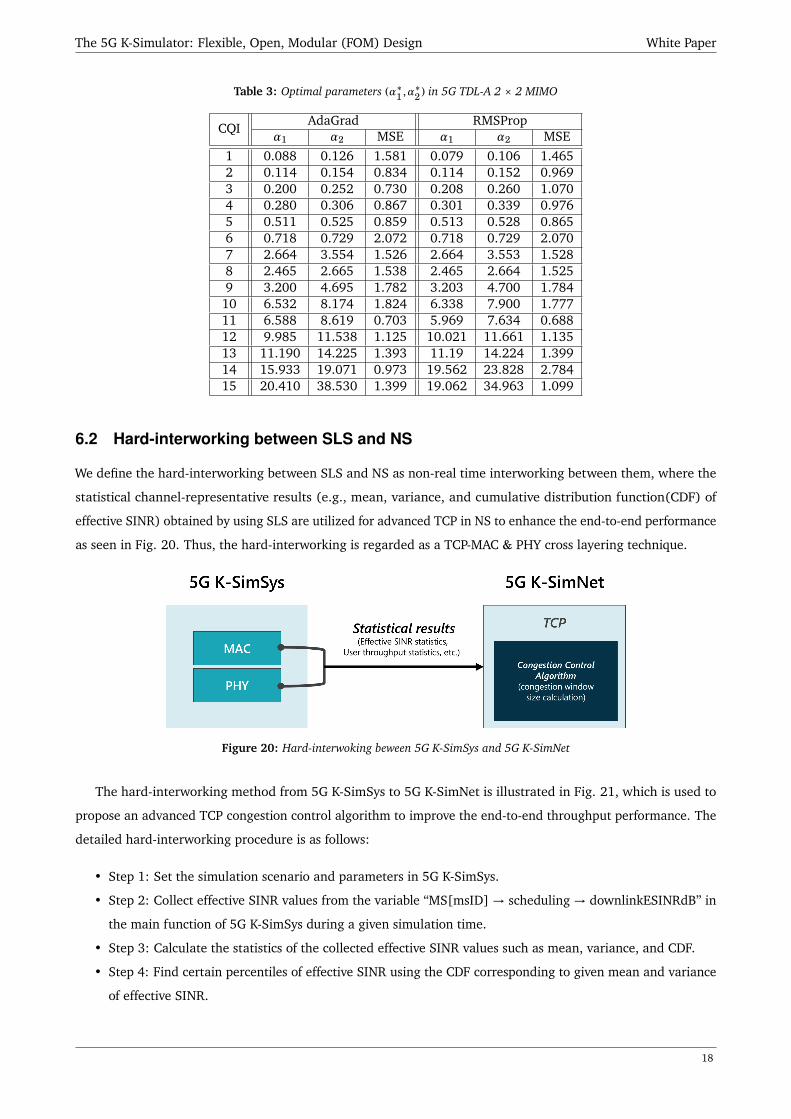
Table 3: Optimal parameters (α∗1 ,α∗2 ) in 5G TDL-A 2 × 2 MIMO
CQI AdaGrad RMSPropα1 α2 MSE α1 α2 MSE
1 0.088 0.126 1.581 0.079 0.106 1.4652 0.114 0.154 0.834 0.114 0.152 0.9693 0.200 0.252 0.730 0.208 0.260 1.0704 0.280 0.306 0.867 0.301 0.339 0.9765 0.511 0.525 0.859 0.513 0.528 0.8656 0.718 0.729 2.072 0.718 0.729 2.0707 2.664 3.554 1.526 2.664 3.553 1.5288 2.465 2.665 1.538 2.465 2.664 1.5259 3.200 4.695 1.782 3.203 4.700 1.78410 6.532 8.174 1.824 6.338 7.900 1.77711 6.588 8.619 0.703 5.969 7.634 0.68812 9.985 11.538 1.125 10.021 11.661 1.13513 11.190 14.225 1.393 11.19 14.224 1.39914 15.933 19.071 0.973 19.562 23.828 2.78415 20.410 38.530 1.399 19.062 34.963 1.099
6.2 Hard-interworking between SLS and NS
We define the hard-interworking between SLS and NS as non-real time interworking between them, where the
statistical channel-representative results (e.g., mean, variance, and cumulative distribution function(CDF) of
effective SINR) obtained by using SLS are utilized for advanced TCP in NS to enhance the end-to-end performance
as seen in Fig. 20. Thus, the hard-interworking is regarded as a TCP-MAC & PHY cross layering technique.
Figure 20: Hard-interwoking beween 5G K-SimSys and 5G K-SimNet
The hard-interworking method from 5G K-SimSys to 5G K-SimNet is illustrated in Fig. 21, which is used to
propose an advanced TCP congestion control algorithm to improve the end-to-end throughput performance. The
detailed hard-interworking procedure is as follows:
• Step 1: Set the simulation scenario and parameters in 5G K-SimSys.
• Step 2: Collect effective SINR values from the variable “MS[msID] → scheduling → downlinkESINRdB” in
the main function of 5G K-SimSys during a given simulation time.
• Step 3: Calculate the statistics of the collected effective SINR values such as mean, variance, and CDF.
• Step 4: Find certain percentiles of effective SINR using the CDF corresponding to given mean and variance
of effective SINR.
18

The 5G K-Simulator: Flexible, Open, Modular (FOM) Design White Paper
• Step 5: Calculate the user-specific congestion window sizes using a scaled Shannon capacity based on the
certain percentiles of effective SINR.
• Step 6: Set the simulation scenario and parameters in 5G K-SimNet that are the same as in 5G K-SimSys.
• Step 7: Apply the user-specific congestion window sizes to the congestion control algorithm in 5G K-SimNet.
Figure 21: Hard interworking procedure
19

The 5G K-Simulator: Flexible, Open, Modular (FOM) Design White Paper
7 5G K-SimPlatform
The 5G K-SimPlatform is designed to provide user-friendly interface and on-line simulation environments. 5G
K-SimPlatform consists of two parts; a web platform and a cloud platform. The web platform provides an interface
for users to execute 5G K-Simulator on the web and represents simulation results through web-based GUI. All
process in web platform is supported by cloud platform, where computing environments are controlled depending
on the number of users accessing the web platform.
7.1 Web platform
The purpose of web platform is to provide high accessibility to the simulator. Users can access 5G K-Simulator
wherever the internet is available. Also, the web platform is designed from the users’ point of view to maximize
users’ convenience. Although source codes of the simulator are provided along with user manuals, it may be difficult
at the beginning of the simulation, and users need enough time to get used to it. For example, developers try to
write source codes easily for users, but some non-expert users or users who are not familiar with programming
language may fail to execute the source code. In order to avoid these situations, the web platform provides a set
of default simulation scenarios to run the simulation easily.
Figure 22: Web platform
Fig. 22 represents the structure of the web platform, which is composed of two parts; a virtual machine (VM)
storage and a server. The VM storage stores source codes and runs the simulation, whereas the server provides a
web-based GUI and a database for simulation results and ‘fast run’ function, respectively. The agent module in
VM storage is used to connect the source codes and the web-based GUI via interface (I/F) server. It transfers the
control signal to handle events, where ‘Simulation START’, ‘Simulation STOP’ and ‘Simulation ALIVE’ commends
are transferred to inform the I/F server the active time of simulation. When the VM is working, the real-time
simulation results are transferred to the server in which the web-based GUI accumulates and processes the real
time results to represent the simulation performance. The database in the server saves the history of simulation
results and allows ‘fast run’ function whenever user configures a system that is same as the one already conducted
20

The 5G K-Simulator: Flexible, Open, Modular (FOM) Design White Paper
Figure 23: Cloud platform
by other users. In other words, ‘fast run’ function loads the saved simulation results from the database without
repeating the same simulation.
The procedures of running the web platform are as follow. User selects the simulation scenarios and sets the
input parameter values. Before running a simulation, the agent module sends a ‘Database Query’ to check whether
the configured simulation setting exists in the database. If it exists, the VM does not start to run the source code,
but the web-based GUI represents the simulation results using the ‘fast run’ function. Otherwise, the VM storage
begins to run the source code and the server displays real time simulation results.
7.2 Cloud platform
The cloud platform is designed to support computing power to the web platform. One of advantages of imple-
menting the cloud platform is that computing resources can be dynamically controlled depending on the number
of users who want to run a simulation using the web platform. For example, when a number of users access
the web platform and want to simulate 5G K-SimLink at the same time, the cloud platform allocates available
computing resources to 5G K-SimLink for parallel operation to cope with abrupt increases in traffic. In case that
only one user accesses the web platform, all computing resources can be assigned to that user for fast simulation.
Therefore, the cloud platform enables the 5G K-SimPlatform to accommodate many users at the same time, and
provides stable and fast simulation environments.
Fig. 23 represents structure of the cloud platform, which is composed of two parts; a VM instance storage and
a VM pool. The VM instance storage is designed to save VM images where each image contains source codes
of the simulator. The VM pool is a set of computing resources, and each VM instance reads VM image in the
VM instance storage to run the source codes. Each VM instance is regarded as an independent simulator, so the
number of active VM instance can vary with the number of users who want to run simulator in the web platform.
The 5G K-SimPlatform develops a cloud manager to monitor the traffic and schedule VM instances dynamically,
which can be realized by transmitting a control commend to the VM pool through the cloud SDK/API.
21
The 5G K-Simulator: Flexible, Open, Modular (FOM) Design White Paper
8 Conclusion
The 5G K-Simulator has been developing in accordance with up-to-date 3GPP specifications. It is ‘open’ to anyone
to use and has a ‘modular’ architecture to add, modify and update by users for their purposes with high ‘flexibility’.
The first 5G simulator, 5G K-Simulator, provides useful references and platform for students, researchers and
experts in the field of communications to encourage their research with well-developed standard simulator.
This will be the reference to validate the 5G potential protocols because it agrees with 3GPP specifications and
performance evaluation methodologies from ITU.
22


