The 1987 vintage CONRAC monochrome avionics video...
32
The 1987 vintage CONRAC monochrome avionics video monitor. Dr. H. Holden. Sept. 2017. (Update Oct. 2017- Source of Black Level Controller discovered –see article end ) The video monitor described in this article is the most exceptional monochrome video monitor I have ever encountered. As this article will show, every aspect of the design & build of this monitor, (614 - 14 inch model) is uncompromising, right through from the mechanical engineering aspects and the materials used, to the circuit design and the component types used. Much of this relates to the fact that the monitor was manufactured for Avionics applications so the components, which are all mil spec types, are of outstanding quality. It appears as though no expense was spared making it and one wonders what the original application might have been. Of note; this monitor does not contain a single electrolytic capacitor. They are all mil spec axial Tantalum types. As nearly everyone in electronics now knows, it is the electrolytic capacitors that are the nemesis to the longevity of most commercial electronic equipment. One of the attractive features of this monitor is the uncluttered and austere nature of its front panel controls (only two controls - brightness & contrast) and the appealing rectangular faced 14 inch CRT. It has a “Retro” appearance and looks like it may well have escaped from a 1960’s vintage Sci-Fi television show, something like Voyage to
Transcript of The 1987 vintage CONRAC monochrome avionics video...
The 1987 vintage CONRAC monochrome
avionics video monitor.
Dr. H. Holden. Sept. 2017. (Update Oct. 2017- Source of Black Level Controller discovered –see article end )
The video monitor described in this article is the most exceptional monochrome video
monitor I have ever encountered.
As this article will show, every aspect of the design & build of this monitor, (614 - 14
inch model) is uncompromising, right through from the mechanical engineering aspects
and the materials used, to the circuit design and the component types used.
Much of this relates to the fact that the monitor was manufactured for Avionics
applications so the components, which are all mil spec types, are of outstanding quality.
It appears as though no expense was spared making it and one wonders what the
original application might have been.
Of note; this monitor does not contain a single electrolytic capacitor. They are all mil
spec axial Tantalum types. As nearly everyone in electronics now knows, it is the
electrolytic capacitors that are the nemesis to the longevity of most commercial
electronic equipment.
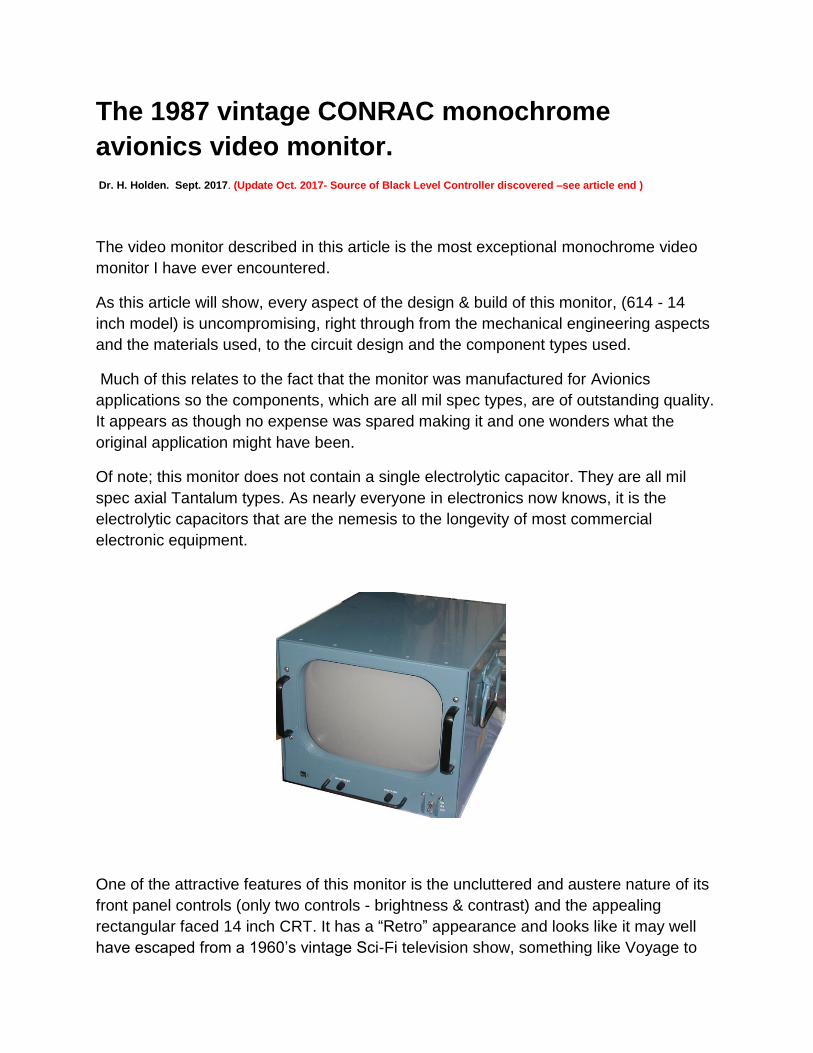
One of the attractive features of this monitor is the uncluttered and austere nature of its
front panel controls (only two controls - brightness & contrast) and the appealing
rectangular faced 14 inch CRT. It has a “Retro” appearance and looks like it may well
have escaped from a 1960’s vintage Sci-Fi television show, something like Voyage to
the Bottom of the Sea, where it would have looked quite at home mounted in one of the
Seaview Submarine’s control panels. Or perhaps a control panel on the Flying Sub. Or
maybe part of the equipment on the Jupiter-2 flying saucer, in the TV series Lost in
Space.
I acquired two of these monitors as NOS parts which had been in their storage bags for
over three decades. The bags had protected them and they were free from damage or
corrosion.
One problem with this sort of avionics monitor is, unlike most commercial monitors,
there is no service manual or schematic readily available. There will be one out there
but I can’t locate it. The only way to safely make it work again is to sit down and
patiently copy out the circuitry by hand to determine the power supply requirements and
other features.
Firstly I documented the power supply and being an avionics monitor it was designed to
be powered by 400Hz three phase 120V (per phase). Or another way to specify this is a
400Hz 208V 3 phase line voltage. An information test data sheet the monitor came with
suggested the power consumption was 50 Watts on test and 80W maximum. It looked
from this sheet that the monitor had been very carefully tested and inspected before it
left the wonderful Conrac factory in 1987, but there was little other useful information
documented there.
I initially did not have this power source in my workshop (but I quickly built one, see end
of article). It was obvious though, after documenting the power supply sections, that this
monitor could be powered by three added compact mains operated switch-mode DC
power supply units that could be put in the monitor’s base. I decide not to do that
though, because I found the nature of the 3 phase system more interesting and I
wanted to leave it original.
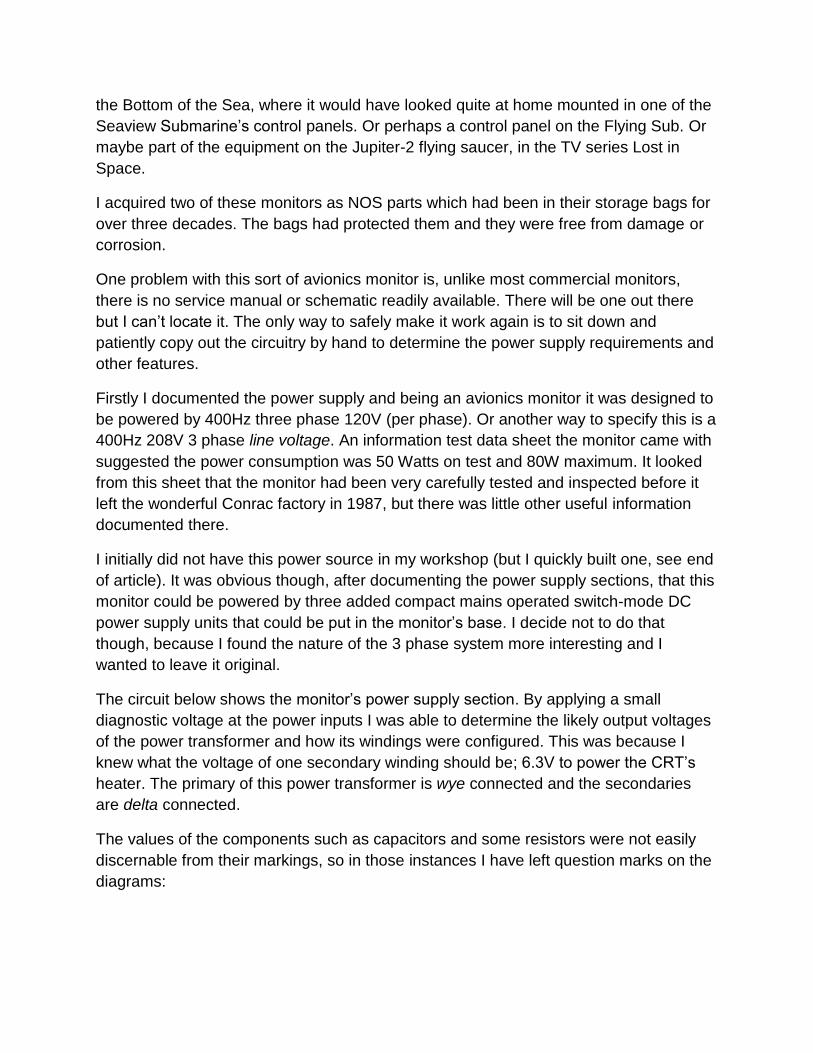
The circuit below shows the monitor’s power supply section. By applying a small
diagnostic voltage at the power inputs I was able to determine the likely output voltages
of the power transformer and how its windings were configured. This was because I
knew what the voltage of one secondary winding should be; 6.3V to power the CRT’s
heater. The primary of this power transformer is wye connected and the secondaries
are delta connected.
The values of the components such as capacitors and some resistors were not easily
discernable from their markings, so in those instances I have left question marks on the
diagrams:
The 400Hz power source is also used to power the hour meter and the cooling fan. The
cooling fan is a single phase 400Hz type. The fan runs at 10,200 RPM and sounds like
a loud jet engine, so I disconnected it and I arranged better convection cooling initially.
Of note there is a very impressive large input 3 phase power filter unit and a three pole
hermetically sealed power switch.
All the wiring is multi-coloured Teflon coated. The delta outputs from the very compact
and shielded 3 phase power transformer are full wave rectified. Since it is full wave 3
phase 400Hz, the ripple voltages are very low. Much less filter capacity is required than
in a 50Hz or 60Hz power system. This is one of the reasons why the designers were
able to avoid electrolytic capacitors in the power supply section, where normally they
are always required for semiconductor based video monitors.
The input connector is a standard Amphenol part and I was able to acquire one easily
on ebay to manufacture a power cable.
The designers at Conrac decided to subdivide the design of the monitor’s electronics
into 6 basic parts:

LVPS. (low voltage power supply pcb)
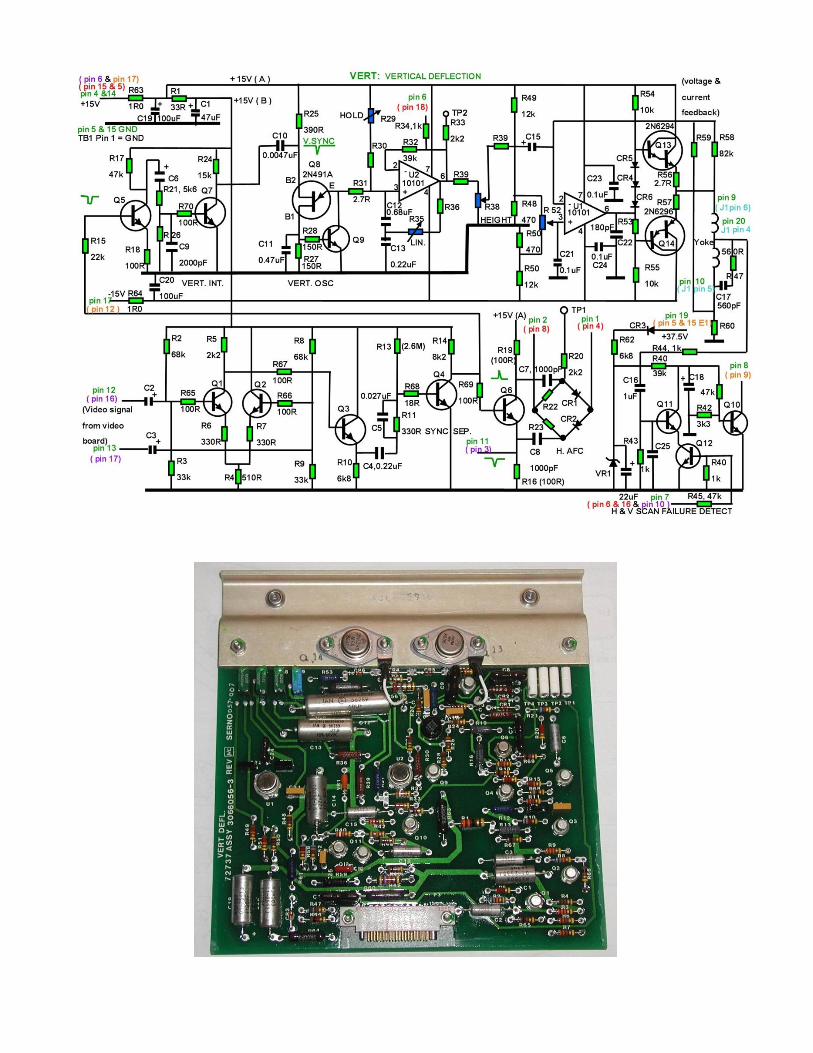
VERT. (vertical deflection pcb)
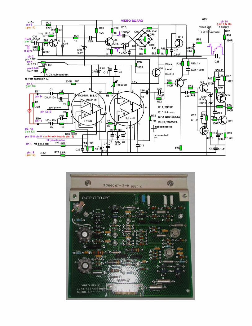
VIDEO. (video signal processing and CRT drive)
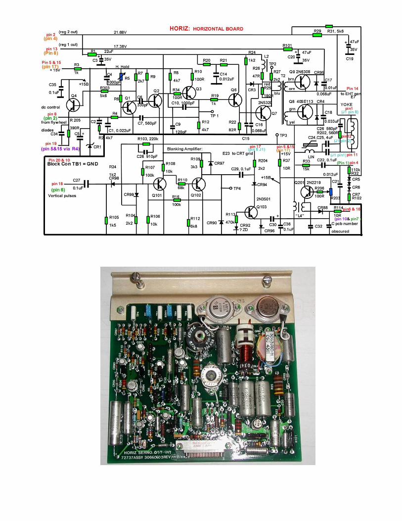
HORIZ. (horizontal deflection & drive to EHT unit)
MOTHERBOARD. (for the above 4 boards)
EHT. (A separate enclosed and shielded EHT unit).
Each of the four pcb’s that live on the motherboard plug into it with a high quality
connector with gold plated pins and the 4 boards are supported and held in place by an
aluminium frame. Two pairs of thumb nut stainless steel locking screws secure the four
boards. Each board has a similar design philosophy:
The boards are 1/8” thick fibreglass (as is the motherboard). Extensive use of ground
planes are used in the track design. The upper part of each board is fixed to a 1/8” thick
treated aluminium metal plate. The plate acts as a heat sink for power semiconductors
where required and as the handle to withdraw the pcb from the carrier when the release
screws are undone.
I realised that it would require that each pcb would have to be documented as there
were quite a few preset controls. Two of these would obviously include the Horizontal
Hold and Vertical Hold controls and to try to find these by experiment could upset other
adjustments.
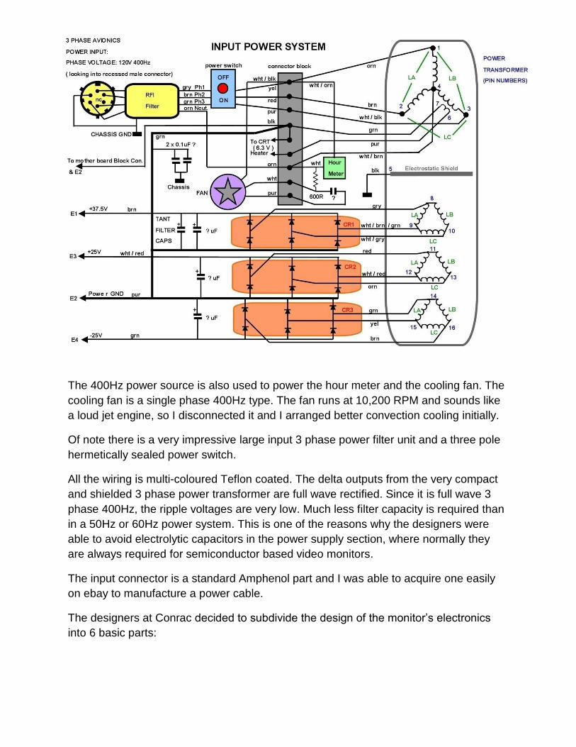
I decided that the best initial move would be to document the motherboard which
provides interconnects between all of the other boards. The easiest way to do this was
simply by documenting the tracks. It is a dual sided pcb. It also contains additional
connectors, for the deflection yoke for example.
I considered it would also help if I assigned colours to the connectors and each of the 4
boards. That would then make it easier to see which pin on a board went to which pin
on another board by using coloured pin labels.
The motherboard diagram is shown below:
Interesting features include the TVS diodes (Cr1 & CR2) on the power supply rails from
the LVPS. Also a GDT (gas discharge tube) protecting the grid circuit of the CRT (these
latter items are on the chassis near the brightness control on the front panel). Connector
J1 passes it leads to another separate D connector (light green) where the yoke plugs
in.
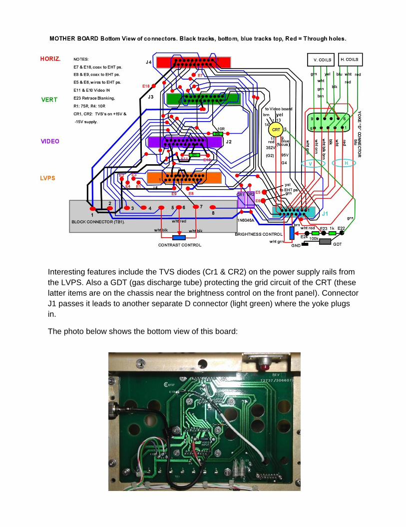
The photo below shows the bottom view of this board:
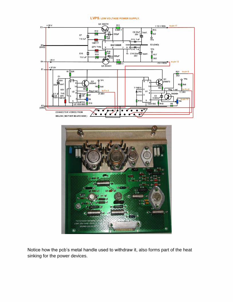
Notice how the pcb’s metal handle used to withdraw it, also forms part of the heat
sinking for the power devices.
Interesting Circuit features:
Horizontal board:
In the horizontal output stage there are two independent output transistors, one for the
horizontal scanning coils and one to drive the EHT assembly. The horizontal oscillator is
DC controlled by the usual push pull AFC circuit where the diodes for this reside on the
vertical deflection board. There is sensing of both H and V scan activity and the
presence of the 37.5V supply, if any of these fail, regulator 1’s output on the LVPS is
shut down, this kills the drive to the EHT unit, shutting off the EHT.
The horizontal board also contains a proper blanking amplifier to ensure the CRT is
properly blanked during H & V retrace time.
It appears as though Q103 (a 2N3501) has been configured as an avalanche device to
protect the CRT’s grid circuit. When the collector-base voltage is exceeded it clamps the
grid circuit. This sub-circuit is not a common arrangement.
Vertical board: The vertical oscillator is based on a UJT which is not a common choice
for this part of the circuit. However, this oscillator will lock immediately to 50Hz or 60Hz
vertical syncs. The H scan oscillator also locks to 15,625 Hz or 15,734 Hz or 15,750 Hz,
so the monitor displays either monochrome Pal or NTSC pictures without the need for
standards switching, which is an unusual feature.
Video board: This board has a differential input for the video signal, presumably to limit
the effects of ground loops. Use is made of the MC1545 (MC1445) differential amplifier
as a gain control block.
This video signal CRT driver circuit has a unique black level stabilization system. The
purpose of DC stabilizing the signal to a fixed voltage at its black level ensures that
changes in picture contrast or content do not affect the black level and background
brightness, which of course it always does if the video signal is AC coupled at any point
prior to the CRT and this is not corrected for.
The common method to stabilize the black level is to do it with a DC restorer diode to
stabilize the sync tip position (and the black level indirectly) or with a black level clamp
circuit. This clamps the voltage after a coupling capacitor to a fixed value on the back
porch of the signal just after the H sync.
However, the method used to perform black level stabilization in this monitor is different,
surprising, creative and brilliant. So it is worth having a closer look at how it works. The
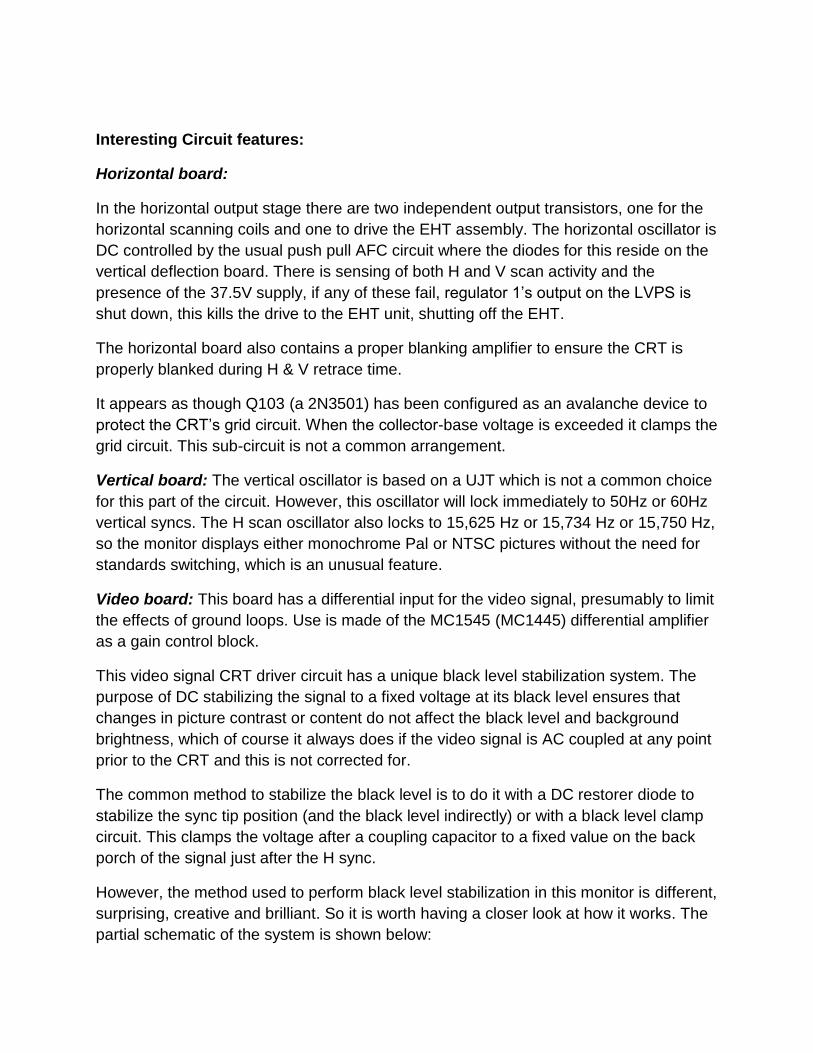
partial schematic of the system is shown below:
Differential gate pulses, coincident with the black level (just after the horizontal sync
pulses) are coupled to a diode bridge. The output from the video amplifier (which feeds
the CRT’s cathode) is divided down by R1 and R2 and applied to the base of Q12. The
diode CR15 in the base circuit temperature compensates the base emitter junction of
temperature dependence of Q12.
The divided down video voltage is applied to CR6 and CR8. In the absence of the gate
pulses, the 4 diodes in the bridge are reverse biased and are not conducting.
Q6 forms a voltage comparator. At first glance this is not obvious. The comparator’s
reference voltage is the threshold at which the base-emitter junction of Q6 starts to
conduct. Because Q6 has a low resistance series base resistor (R68) and Q6’s emitter
is connected to +5.1V, the voltage during circuit operation on the junction of CR7 and
CR9 appears stable at about 5.75V after activation of the diode bridge.
The video signal is AC coupled into the output amplifier’s input by C16. However C16
would want to progressively charge up by R36. Any collector current via Q6 takes it the
other way discharging C16. When the gate pulses are applied, the 4 diodes in the
bridge conduct.
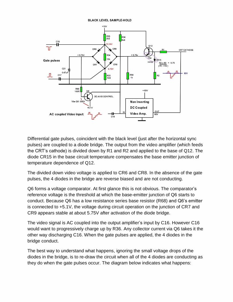
The best way to understand what happens, ignoring the small voltage drops of the
diodes in the bridge, is to re-draw the circuit when all of the 4 diodes are conducting as
they do when the gate pulses occur. The diagram below indicates what happens:
The divided down video output voltage is passed from Q12’s emitter circuit to the loop
filter capacitor C21. In practice because of the low value of R68, the voltage during
operation across C21 appears stable. However, if for example the output voltage had
climbed to say 65V the base current in Q6 increases, therefore its collector current
increases discharging C16 and lowering the video amplifier’s input voltage, returning the
output voltage to the fixed value of 60V during the black level or back porch period.
Likewise if the output voltage was lower than 60V at the moment of the gate pulses,
then Q6’s base current decreases and so does its collector current, allowing R36 to
charge C16 to a higher voltage. The circuit stabilizes and “rests on the knee” of the
conduction point of Q6’s base-emitter voltage and this serves as the “reference voltage”
for this feedback system or “black level servo system”.
The circuit therefore is a type of gated negative feedback circuit and in this way the
black level of the video voltage remains stable, regardless of the contrast levels or
picture content. A possible advantage of this circuit, over a standard clamp, is relative
immunity to noise pulses.
One might wonder what happens if the gate pulses disappear in the absence of video
signal or horizontal sync? It turns out they don’t. This is because a horizontal pulse gets
coupled from the H sync discriminator circuit via CR2 and the coupling capacitor C8 to
the emitter of the sync phase splitter (Q6 on the vertical board). So the black level servo
control system is still active in the absence of an input video signal. If it were not, Q6 on
the video board would turn off and the picture tube cathode voltage would float up from
60V to 80V cutting off the beam.
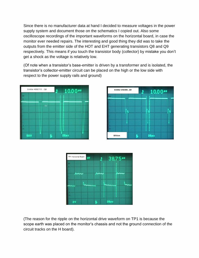
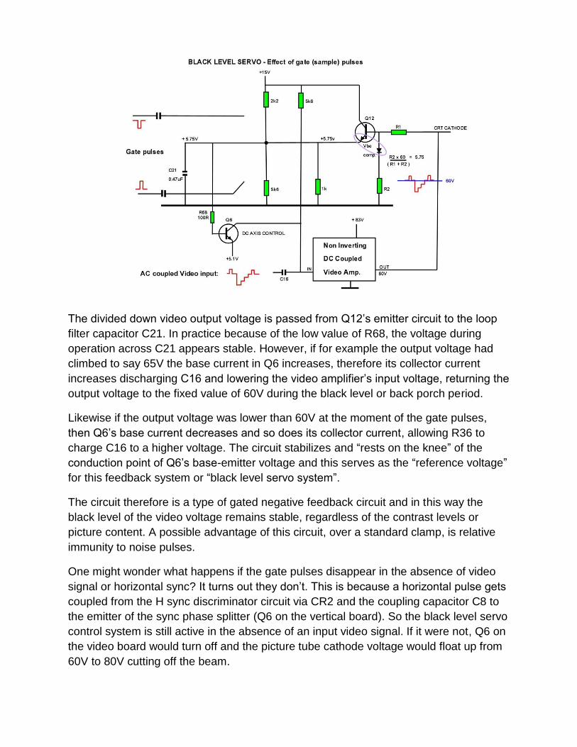
Since there is no manufacturer data at hand I decided to measure voltages in the power
supply system and document those on the schematics I copied out. Also some
oscilloscope recordings of the important waveforms on the horizontal board, in case the
monitor ever needed repairs. The interesting and good thing they did was to take the
outputs from the emitter side of the HOT and EHT generating transistors Q8 and Q9
respectively. This means if you touch the transistor body (collector) by mistake you don’t
get a shock as the voltage is relatively low.
(Of note when a transistor’s base-emitter is driven by a transformer and is isolated, the
transistor’s collector-emitter circuit can be placed on the high or the low side with
respect to the power supply rails and ground)
(The reason for the ripple on the horizontal drive waveform on TP1 is because the
scope earth was placed on the monitor’s chassis and not the ground connection of the
circuit tracks on the H board).
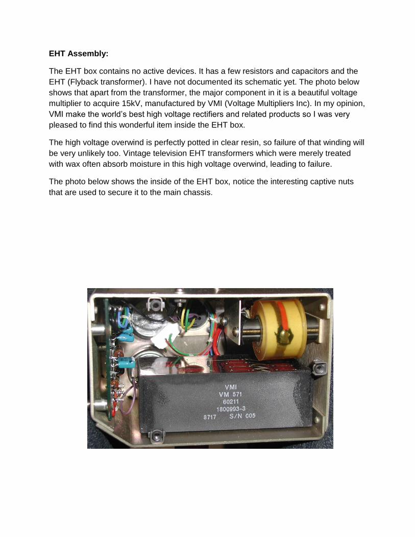
EHT Assembly:
The EHT box contains no active devices. It has a few resistors and capacitors and the
EHT (Flyback transformer). I have not documented its schematic yet. The photo below
shows that apart from the transformer, the major component in it is a beautiful voltage
multiplier to acquire 15kV, manufactured by VMI (Voltage Multipliers Inc). In my opinion,
VMI make the world’s best high voltage rectifiers and related products so I was very
pleased to find this wonderful item inside the EHT box.
The high voltage overwind is perfectly potted in clear resin, so failure of that winding will
be very unlikely too. Vintage television EHT transformers which were merely treated
with wax often absorb moisture in this high voltage overwind, leading to failure.
The photo below shows the inside of the EHT box, notice the interesting captive nuts
that are used to secure it to the main chassis.
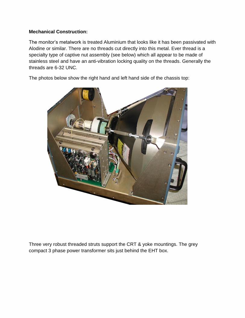
Mechanical Construction:
The monitor’s metalwork is treated Aluminium that looks like it has been passivated with
Alodine or similar. There are no threads cut directly into this metal. Ever thread is a
specialty type of captive nut assembly (see below) which all appear to be made of
stainless steel and have an anti-vibration locking quality on the threads. Generally the
threads are 6-32 UNC.
The photos below show the right hand and left hand side of the chassis top:
Three very robust threaded struts support the CRT & yoke mountings. The grey
compact 3 phase power transformer sits just behind the EHT box.
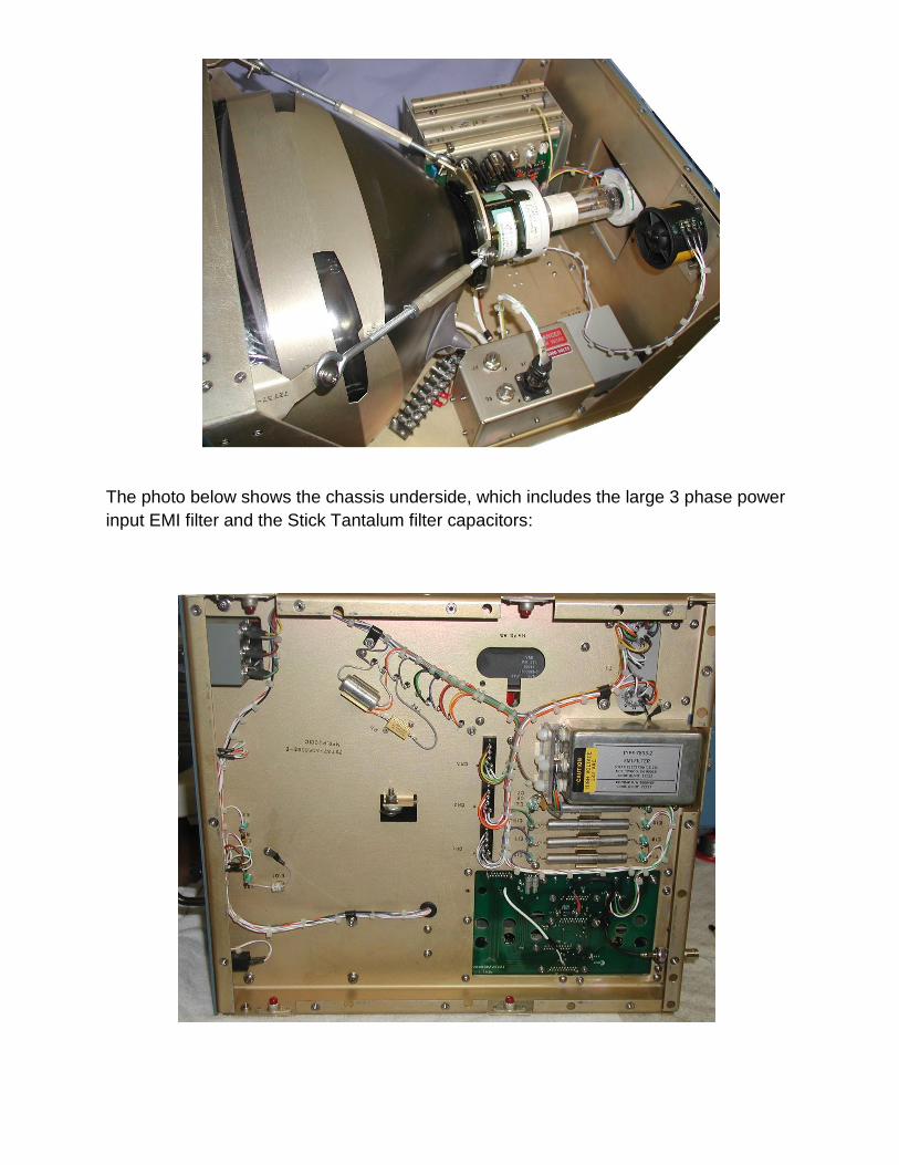
The photo below shows the chassis underside, which includes the large 3 phase power
input EMI filter and the Stick Tantalum filter capacitors:
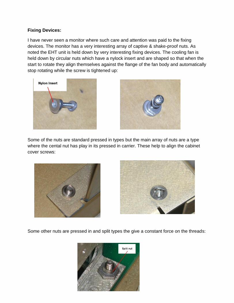
Fixing Devices:
I have never seen a monitor where such care and attention was paid to the fixing
devices. The monitor has a very interesting array of captive & shake-proof nuts. As
noted the EHT unit is held down by very interesting fixing devices. The cooling fan is
held down by circular nuts which have a nylock insert and are shaped so that when the
start to rotate they align themselves against the flange of the fan body and automatically
stop rotating while the screw is tightened up:
Some of the nuts are standard pressed in types but the main array of nuts are a type
where the cental nut has play in its pressed in carrier. These help to align the cabinet
cover screws:
Some other nuts are pressed in and split types the give a constant force on the threads:
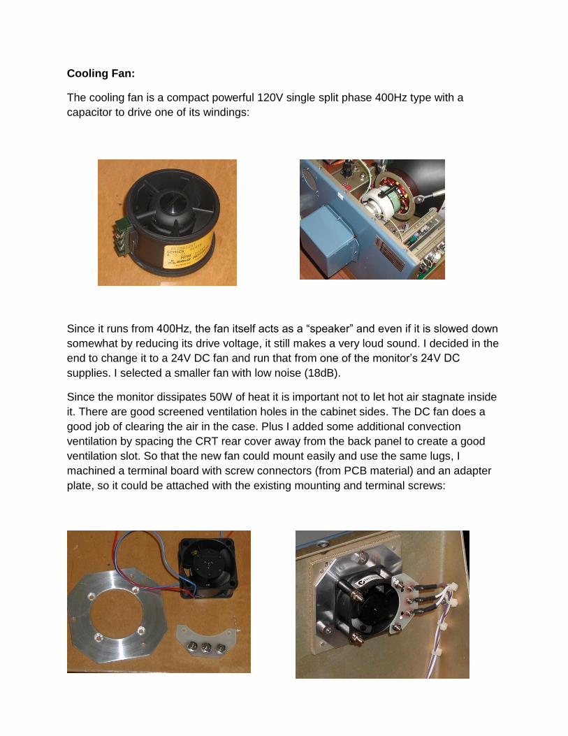
Cooling Fan:
The cooling fan is a compact powerful 120V single split phase 400Hz type with a
capacitor to drive one of its windings:
Since it runs from 400Hz, the fan itself acts as a “speaker” and even if it is slowed down
somewhat by reducing its drive voltage, it still makes a very loud sound. I decided in the
end to change it to a 24V DC fan and run that from one of the monitor’s 24V DC
supplies. I selected a smaller fan with low noise (18dB).
Since the monitor dissipates 50W of heat it is important not to let hot air stagnate inside
it. There are good screened ventilation holes in the cabinet sides. The DC fan does a
good job of clearing the air in the case. Plus I added some additional convection
ventilation by spacing the CRT rear cover away from the back panel to create a good
ventilation slot. So that the new fan could mount easily and use the same lugs, I
machined a terminal board with screw connectors (from PCB material) and an adapter
plate, so it could be attached with the existing mounting and terminal screws:
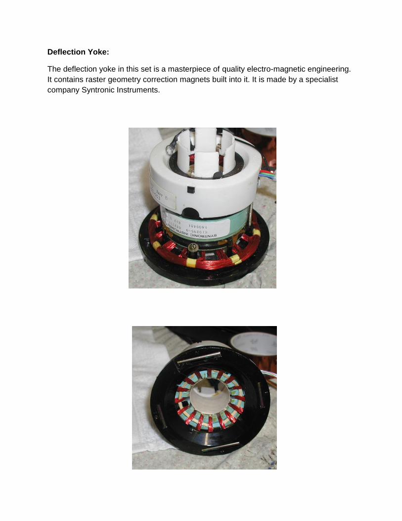
Deflection Yoke:
The deflection yoke in this set is a masterpiece of quality electro-magnetic engineering.
It contains raster geometry correction magnets built into it. It is made by a specialist
company Syntronic Instruments.
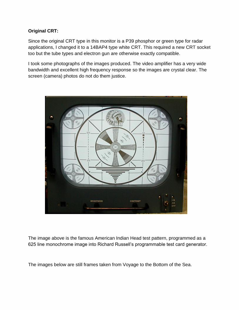
Original CRT:
Since the original CRT type in this monitor is a P39 phosphor or green type for radar
applications, I changed it to a 14BAP4 type white CRT. This required a new CRT socket
too but the tube types and electron gun are otherwise exactly compatible.
I took some photographs of the images produced. The video amplifier has a very wide
bandwidth and excellent high frequency response so the images are crystal clear. The
screen (camera) photos do not do them justice.
The image above is the famous American Indian Head test pattern, programmed as a
625 line monochrome image into Richard Russell’s programmable test card generator.
The images below are still frames taken from Voyage to the Bottom of the Sea.
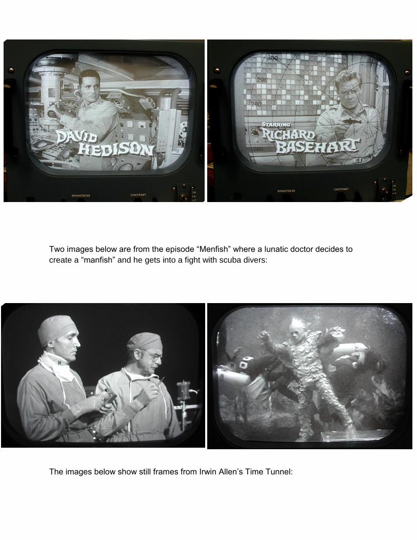
Two images below are from the episode “Menfish” where a lunatic doctor decides to
create a “manfish” and he gets into a fight with scuba divers:
The images below show still frames from Irwin Allen’s Time Tunnel:
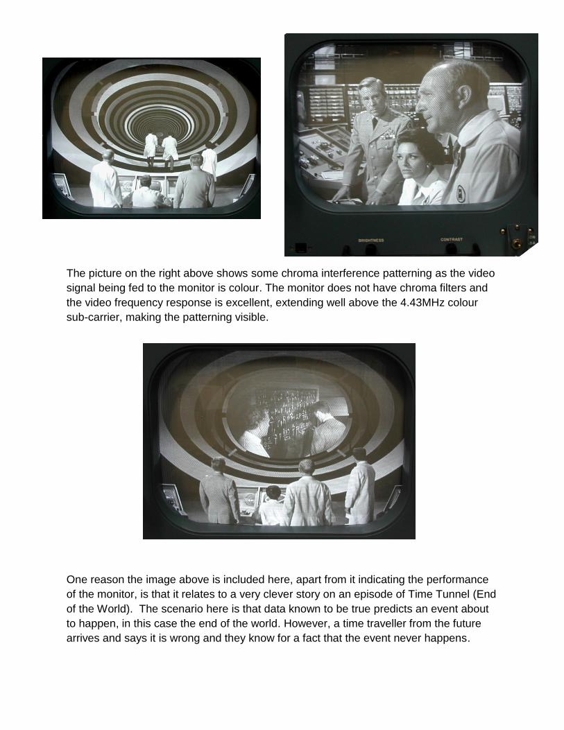
The picture on the right above shows some chroma interference patterning as the video
signal being fed to the monitor is colour. The monitor does not have chroma filters and
the video frequency response is excellent, extending well above the 4.43MHz colour
sub-carrier, making the patterning visible.
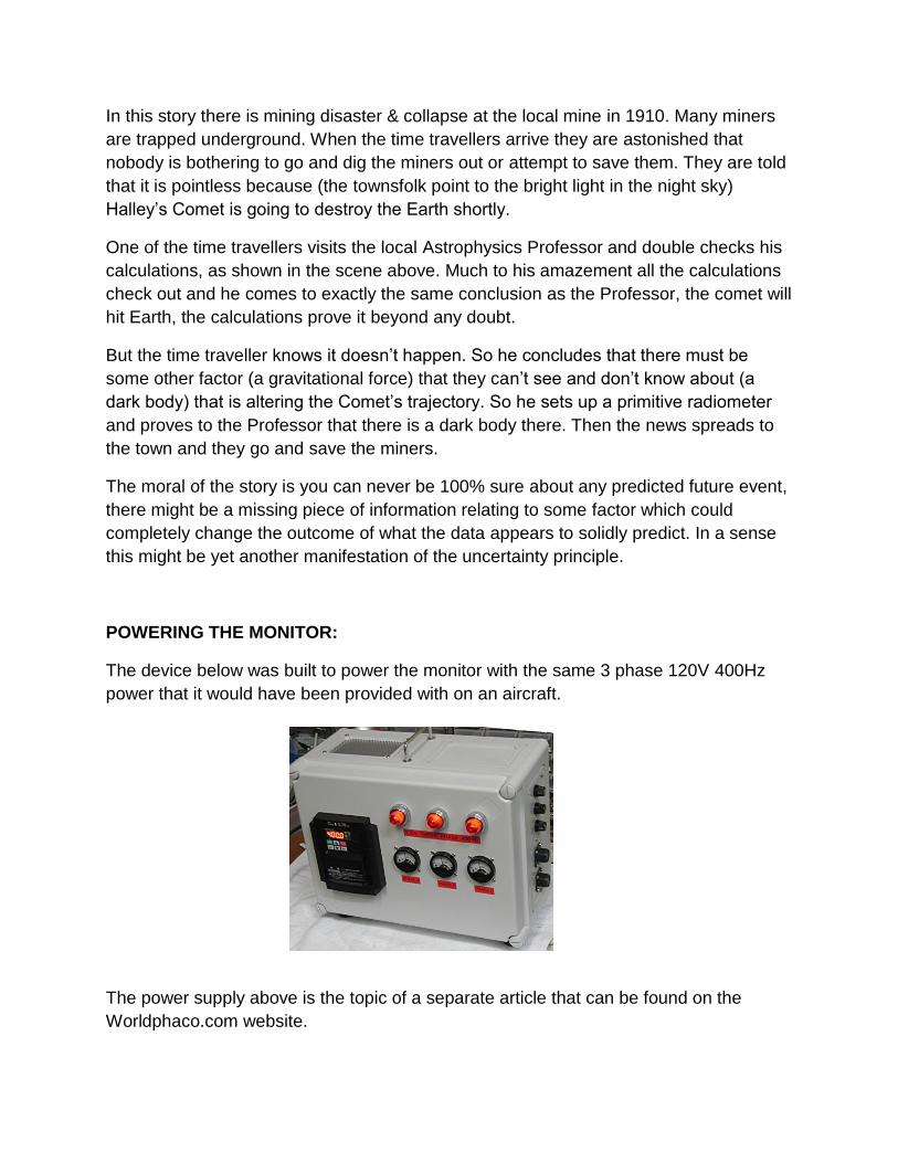
One reason the image above is included here, apart from it indicating the performance
of the monitor, is that it relates to a very clever story on an episode of Time Tunnel (End
of the World). The scenario here is that data known to be true predicts an event about
to happen, in this case the end of the world. However, a time traveller from the future
arrives and says it is wrong and they know for a fact that the event never happens.
In this story there is mining disaster & collapse at the local mine in 1910. Many miners
are trapped underground. When the time travellers arrive they are astonished that
nobody is bothering to go and dig the miners out or attempt to save them. They are told
that it is pointless because (the townsfolk point to the bright light in the night sky)
Halley’s Comet is going to destroy the Earth shortly.
One of the time travellers visits the local Astrophysics Professor and double checks his
calculations, as shown in the scene above. Much to his amazement all the calculations
check out and he comes to exactly the same conclusion as the Professor, the comet will
hit Earth, the calculations prove it beyond any doubt.
But the time traveller knows it doesn’t happen. So he concludes that there must be
some other factor (a gravitational force) that they can’t see and don’t know about (a
dark body) that is altering the Comet’s trajectory. So he sets up a primitive radiometer
and proves to the Professor that there is a dark body there. Then the news spreads to
the town and they go and save the miners.
The moral of the story is you can never be 100% sure about any predicted future event,
there might be a missing piece of information relating to some factor which could
completely change the outcome of what the data appears to solidly predict. In a sense
this might be yet another manifestation of the uncertainty principle.
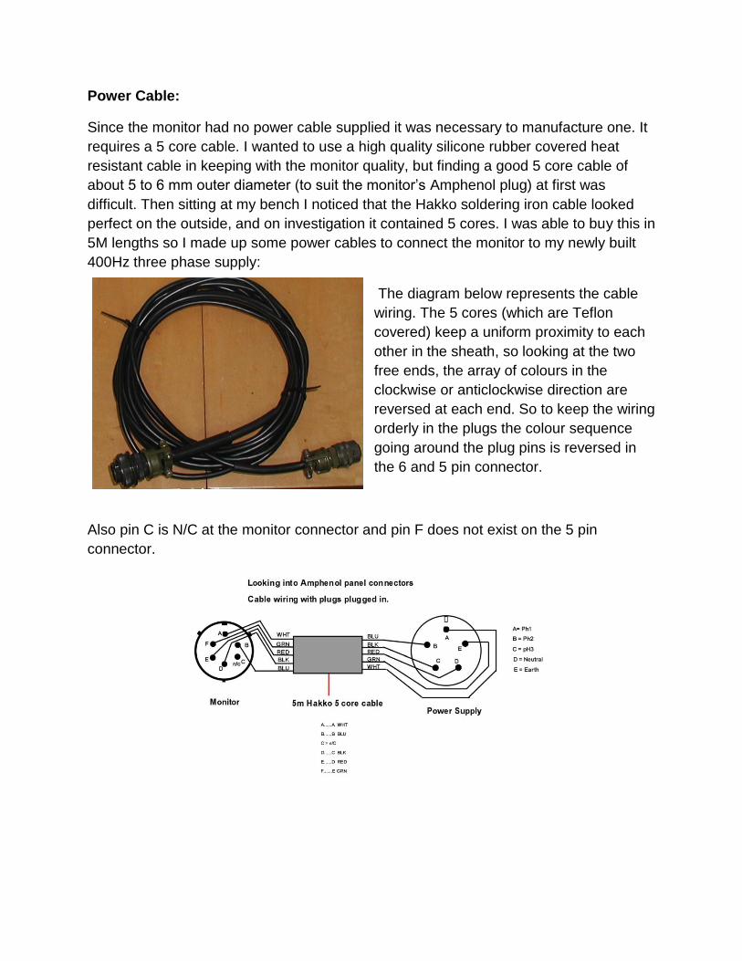
POWERING THE MONITOR:
The device below was built to power the monitor with the same 3 phase 120V 400Hz
power that it would have been provided with on an aircraft.
The power supply above is the topic of a separate article that can be found on the
Worldphaco.com website.
Power Cable:
Since the monitor had no power cable supplied it was necessary to manufacture one. It
requires a 5 core cable. I wanted to use a high quality silicone rubber covered heat
resistant cable in keeping with the monitor quality, but finding a good 5 core cable of
about 5 to 6 mm outer diameter (to suit the monitor’s Amphenol plug) at first was
difficult. Then sitting at my bench I noticed that the Hakko soldering iron cable looked
perfect on the outside, and on investigation it contained 5 cores. I was able to buy this in
5M lengths so I made up some power cables to connect the monitor to my newly built
400Hz three phase supply:
The diagram below represents the cable
wiring. The 5 cores (which are Teflon
covered) keep a uniform proximity to each
other in the sheath, so looking at the two
free ends, the array of colours in the
clockwise or anticlockwise direction are
reversed at each end. So to keep the wiring
orderly in the plugs the colour sequence
going around the plug pins is reversed in
the 6 and 5 pin connector.
Also pin C is N/C at the monitor connector and pin F does not exist on the 5 pin
connector.
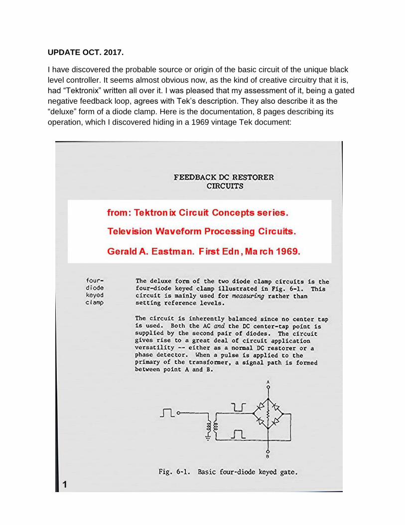
UPDATE OCT. 2017.
I have discovered the probable source or origin of the basic circuit of the unique black
level controller. It seems almost obvious now, as the kind of creative circuitry that it is,
had “Tektronix” written all over it. I was pleased that my assessment of it, being a gated
negative feedback loop, agrees with Tek’s description. They also describe it as the
“deluxe” form of a diode clamp. Here is the documentation, 8 pages describing its
operation, which I discovered hiding in a 1969 vintage Tek document:
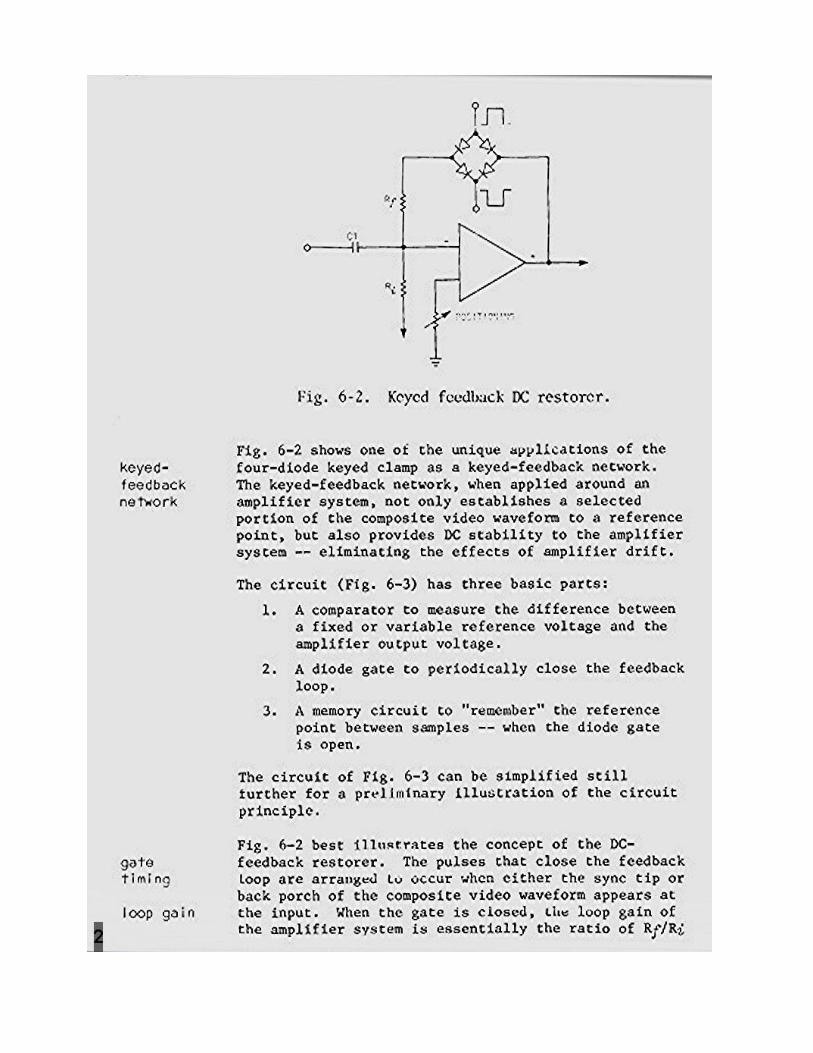
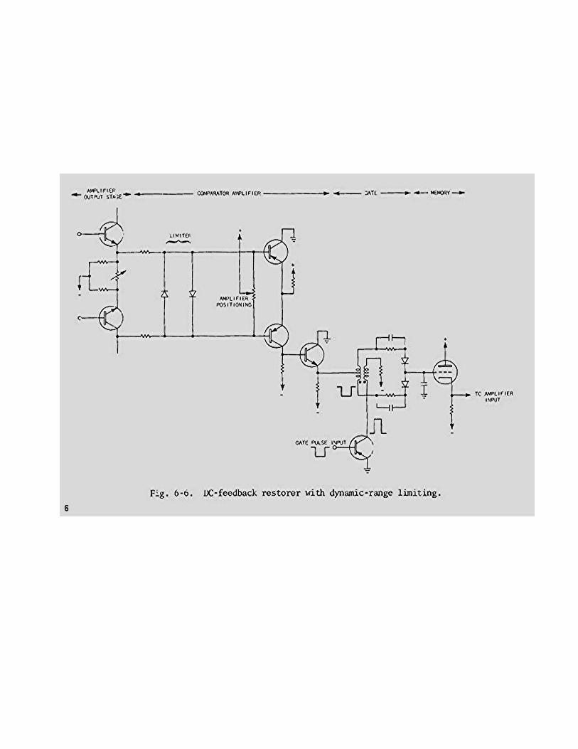
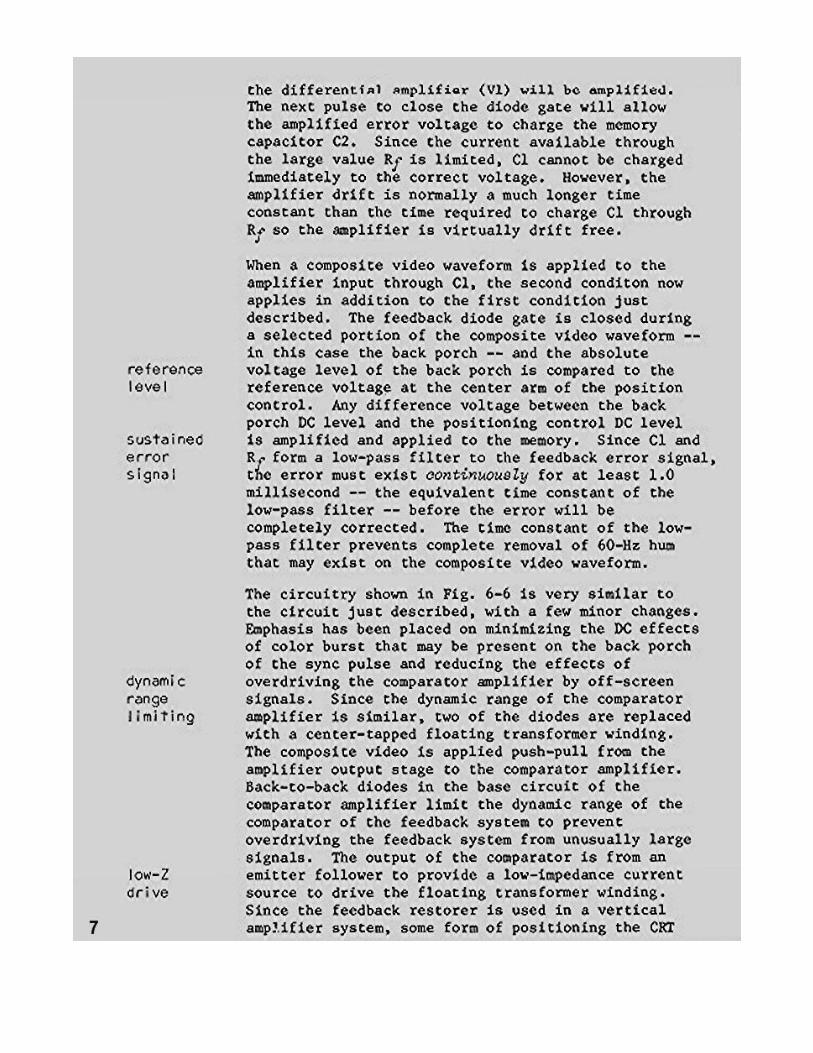
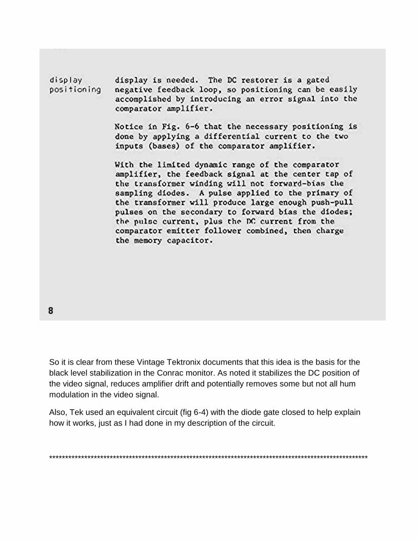
So it is clear from these Vintage Tektronix documents that this idea is the basis for the
black level stabilization in the Conrac monitor. As noted it stabilizes the DC position of
the video signal, reduces amplifier drift and potentially removes some but not all hum
modulation in the video signal.
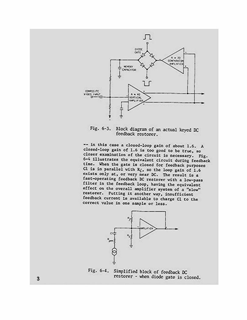
Also, Tek used an equivalent circuit (fig 6-4) with the diode gate closed to help explain
how it works, just as I had done in my description of the circuit.
****************************************************************************************************