
TH~ CALCULATION OF LIGHTING, WITH LINEAR SOURCES OF LIGHT Bound... · 'TH~ CALCULATION OF LIGHTING,...
7
'!- MAY'1941 ........ . '-;, ,147 , ' 'TH~ CALCULATION OF LIGHTING, IN~TALLATIONS WITH LINEAR SOURCES OF LIGHT . Several' diagrams are 'de~ived which make it possible to determine in a simple way the Il- lumination, and from it the luminous efficiency for ins'tallations' equipped with- linear light sources.' ' In designing a lighting system with ordinary electric lamps and normal fittings one can make use of extensive factual material, of a theoretical as .wel! as of an empirical nature, .ab~ut the distribution of the illumination:with :the customary arrangement of the light sources. In the literature more or less detailed information can he' found, which is usuallly arranged in the form of tables 1 ) and in' , general is sufficiently accurate for practical use. The modern linear sources of light, however, such as the "Philora.'; TL lamps. are entirely different from the lamps generally used until now with respect not only to the distribution of their luminous flux ... but also to the way in which they are installed in the rooms to be illuminated, so that the experience which has been gained with earlier lighting systems' , cannot be directly applied to them, The number of ~y~;ems already installed with such linear light sources is still too small to make it possible to col- lect adequate experimental data: from them, It is therefore necessary for the present to cal~ulate the distribution of the luminous flux for linear light . sources theoretically; as 'was also formerly the On the working surface, in addition to the direct' case fo~ ordinary systems' with ordinary electric radiation a), is.also incident , lamps: Fro~ this the so-called luminous efficiency' 1) part of the flux which' has been reflected once " of the system can easily be found. This ~is of by the ceiling or by the reflectors in whièh the course a more elaborate method than consulting lamps are placed, . a table, but it is unavoidable until such practical 2) part of the" flux 'which .has been reflected once tables have been crystallized out of many calcul~- ' by the walls of the room and tions confirmed by illumination méasuréments. 3) part of the, flux which hás b~~n 'reflected re- Moreover, it offers the opportunity ~f attaining a peatèdly between "the walls and the ceiling' or ,clearer' insight into' the problems in question than between thê various wall;.", :,' .' '.' is usually obtained by the mechanical calculation It is in general therefore permissible in such con- with tables.' siderations to assume that only the part of the room' Illumination systems with linear light sources which ~shigher than the working plane' takes part usually consist of tubes which are mounted horizo~- t 'i~ the repeated reflections, while the contribution tally close under the ceiling with or- without re- from surfaces which are in or below the working flectors, Such a system must then provide the great- _surface may be neglècted, , ''. est possible illumination on the tables present in' Of the four different contributions to the total the room; which generally have their 'working illumination of the working 'plane which have been mentioned in the foregoing, the direct illumi- , nation will in general be by far the 'most important. -This contribution should therefore be 'caléulated accurately' within reasonable limits. The other .. by H. ZIJL. ',' .Ïntroduction , ' ~ .. , r !~ . ~' . , " , .1) Such tables are as a rule based upon the original inves- tigations of W. Harrison and E. A. Anderson, Trans. LE.S., n, 67, 1916. , 535.241; 628.93 -" surface 'about '1 m above the floor. The luminous flux from the lamps niky. hè divided i~to three parts (jig. 1) which are incident: " a). directly on the working surface, b) directly on the ceiling or the inner surface-of the reflector, and c) on the walls .of the room: .. b -, J8225 .,_ -~~.' Fig: 1. ~h~'linear l.ight sou~c'e L_ is placed against the ceiling. The radiation a strikes tile working surface V directlv while b is directed toward the ceiling and c toward the walis: • I. '. , .. ,.•... ", '~ ._ ;:' . " " ':.. ,.- ~.
Transcript of TH~ CALCULATION OF LIGHTING, WITH LINEAR SOURCES OF LIGHT Bound... · 'TH~ CALCULATION OF LIGHTING,...
'! -
MAY'1941
......... '-;,
,147
, '
'TH~ CALCULATION OF LIGHTING, IN~TALLATIONS WITH LINEARSOURCES OF LIGHT
. Several' diagrams are 'de~ived which make it possible to determine in a simple way the Il-lumination, and from it the luminous efficiency for ins'tallations' equipped with- linearlight sources.' '
In designing a lighting system with ordinaryelectric lamps and normal fittings one can make useof extensive factual material, of a theoretical as.wel! as of an empirical nature, .ab~ut the distributionof the illumination:with :the customary arrangementof the light sources. In the literature more orless detailed information can he' found, whichis usuallly arranged in the form of tables1) and in'
, general is sufficiently accurate for practical use. Themodern linear sources of light, however, such asthe "Philora.'; TL lamps. are entirely different fromthe lamps generally used until now with respectnot only to the distribution of their luminous flux
... but also to the way in which they are installed inthe rooms to be illuminated, so that the experiencewhich has been gained with earlier lighting systems', cannot be directly applied to them, The number of~y~;ems already installed with such linear lightsources is still too small to make it possible to col-lect adequate experimental data: from them, It istherefore necessary for the present to cal~ulate thedistribution of the luminous flux for linear light
. sources theoretically; as 'was also formerly the On the working surface, in addition to the direct'case fo~ ordinary systems' with ordinary electric radiation a), is.also incident
, lamps: Fro~ this the so-called luminous efficiency' 1) part of the flux which' has been reflected once "of the system can easily be found. This ~is of by the ceiling or by the reflectors in whièh thecourse a more elaborate method than consulting lamps are placed, .a table, but it is unavoidable until such practical 2) part of the" flux 'which .has been reflected oncetables have been crystallized out of many calcul~- ' by the walls of the room andtions confirmed by illumination méasuréments. 3) part of the, flux which hás b~~n 'reflected re-Moreover, it offers the opportunity ~f attaining a peatèdly between "the walls and the ceiling' or, clearer' insight into' the problems in question than between thê various wall;.", :,' .' '.'is usually obtained by the mechanical calculation It is in general therefore permissible in such con-with tables.' siderations to assume that only the part of the room'
Illumination systems with linear light sources which ~s higher than the working plane' takes partusually consist of tubes which are mounted horizo~- t 'i~ the repeated reflections, while the contributiontally close under the ceiling with or- without re- from surfaces which are in or below the workingflectors, Such a system must then provide the great- _surface may be neglècted, , ' ' .est possible illumination on the tables present in' Of the four different contributions to the totalthe room; which generally have their 'working illumination of the working 'plane which have
been mentioned in the foregoing, the direct illumi- ,nation will in general be by far the 'most important.-This contribution should therefore be 'caléulatedaccurately' within reasonable limits. The other
.. by H. ZIJL.
','
.Ïntroduction
, '
~.. ,
r !~. ~'
.,"
, . 1) Such tables are as a rule based upon the original inves-tigations of W. Harrison and E. A. Anderson, Trans.LE.S., n, 67, 1916.
, 535.241; 628.93
-"
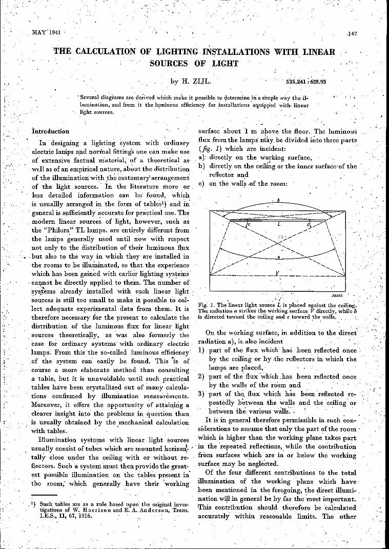
surface 'about '1 m above the floor. The luminousflux from the lamps niky. hè divided i~to three parts(jig. 1) which are incident: "a). directly on the working surface,b) directly on the ceiling or the inner surface-of the
reflector, andc) on the walls .of the room:
..
b
-,
J8225.,_ -~~.'
Fig: 1. ~h~ 'linear l.ight sou~c'eL_ is placed against the ceiling.The radiation a strikes tile working surface V directlv while bis directed toward the ceiling and c toward the walis:
• I. '. ,
..,.•...
", '~ ._
;:' .
" "
': ..
,.- ~.
148 PHILIPS TECHNICALREVIEW Vol. 6, No. S
The contribution dEa of this to thè illumination(expressed in 104 lux, since we calculate with cminstead ofm) at point 0 on the plane,ABeD situated
2) N. A. Halbertsma and G. P. Ittmann, Philips techn.' at. a distance h cm from the linear light source isRev., 4, 181, 1939. 'given by:
'contribu,tions are usually successively smaller in'the order in which they are 'mentioned, and maytherefore be calculated less accurately withoutcausing important errors in the final result.Since, moreover, the calculation of these smaller
, contributions is fundamentally the same ~s in thecase of ordinary lighting systems, or otherwisethe same as that which ;vill .be given in this articlefor the direct illumination produced by the linearlight sources, we shall here concern ourselveschiefly with the calculation of the direct illumi-nation intensity.
The calculation 'of the direct' illumination withlinear sources of light
In this calculation of illumination provided bylinear light sources we shall begin with the simpleconsiderations which have already been given inthis periodical 2) about the light distribution of'these sources. We assume that the surface ~f theT~ lamp (fig~ 2) radiates diffusely according to
C
A~dl I
3~5cm ?rl-B.~ ~- IL i I , i .1IOO~ J82:2tS
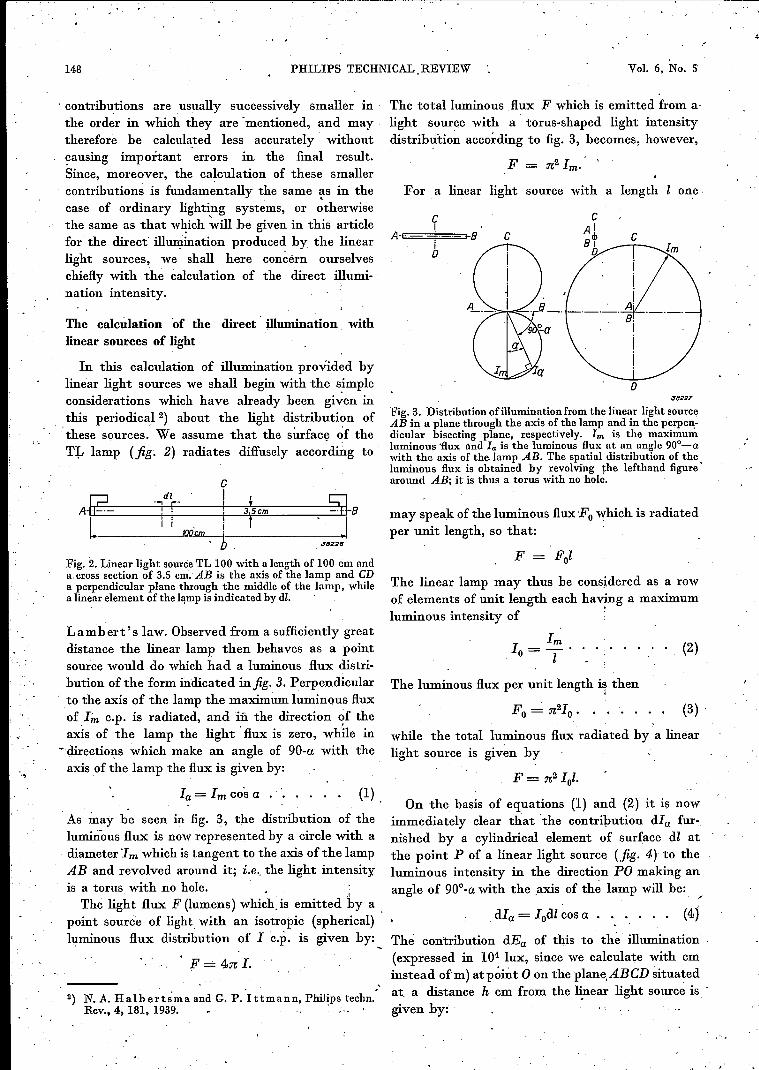
Fig. 2. Linear light source TL 100 with a length of 100 cm anda.crosssection of 3.5 cm.AB is the axis of the lamp and CDa perpendicular plane through the middle of the lamp, whilea linearelementof the lamp is indicated by dl.
'"
Lambert's law. Observed from a sufficiently greatdistance the linear lamp then behaves as a pointsource would do which had a luminous flux distri-bution of the form indicated infig. 3. Perpendicularto the axis of the lamp the maximum luminous fluxof1~ c.p. is radiated, and ill the direction of theaxis of the lamp the light' flux is zero, while in
¥ directions which make an angle of 90-a with theaxis of the lamp the flux is given by:
Ia= Imcos a . '.
As may be seen in fig. 3, the distribution of theluminous flux is now represented by a circle with adiameter 1mwhich is tangent to the axis of the lampAB and revolved around it; i;e; the light intensityis a torus with no hole.. - ..\
, The light flux F (lumens) which, is emitted by a ,point source of light with an isotropic (spherical)luminous flux distribution of I c.p, is given by:
F ....:..4:n; I.
The totalluminous flux F which is emitted from a-light source with a torus-shaped light intensitydistrib~'tion according to fig. 3, becomes, however,
F = :n;2Im.
For a linear light source with a length onc,
CA+
!+B--r C C
I0
J822T
Fig. 3. Distributionofilluminationfromthe linear light sourceAB in a plane through the axis of the lamp and in the perpeIl:-dicular bisecting plane, respectively. I", is the maximumluminous 'flux and la is the luminous flux at an angle90o-awith the axis of the,lamp AB. The spatial distribution. of theluminous flux is obtained by revolving the lefthand figure'around AB; it is thus a torus with no hole.
may speak of the luminous flux Fo which is radiatedper unit length, so that:
F = Fol
The linear lamp may thus be considered as a rowof elements of unit length each ha'1ng a maximumluminous intensity of
Im10=-'
l. . . . (2)
The luminous flux per unit length i~ then
(3) ,
while the total luminous flux radiated by a linearlight source is given by
(1)F= :n;2Iol.
On the basis of equations (1) and (2) it is nowimmediately clear that 'the contribution dIa fur-nished by a cylindrical clement of surface dl atthe point P of a linear light source (.fig. 4) to theluminous intensity in the direction PO making anangle of 90o-a with the axis of the lamp will be: ,
dIa = Iodl cos a . . . . . . (4)
·'
,;LIGHTING INSTALLATIONS WITH ,LINEAR SOURCES 149MAY 1941
dI~ , 10dEa = -2 cos Y = '2 dl cosa cosy,
T T
where T represents the' distance' OP in cm: and ythe angle between the direction of radiation PO 'and the vertical to the irradiated plane ABeD.If we call the perpendicular dista~ce from the point'0 to the linear light source a (cm), then the contri-
AJ8228
"
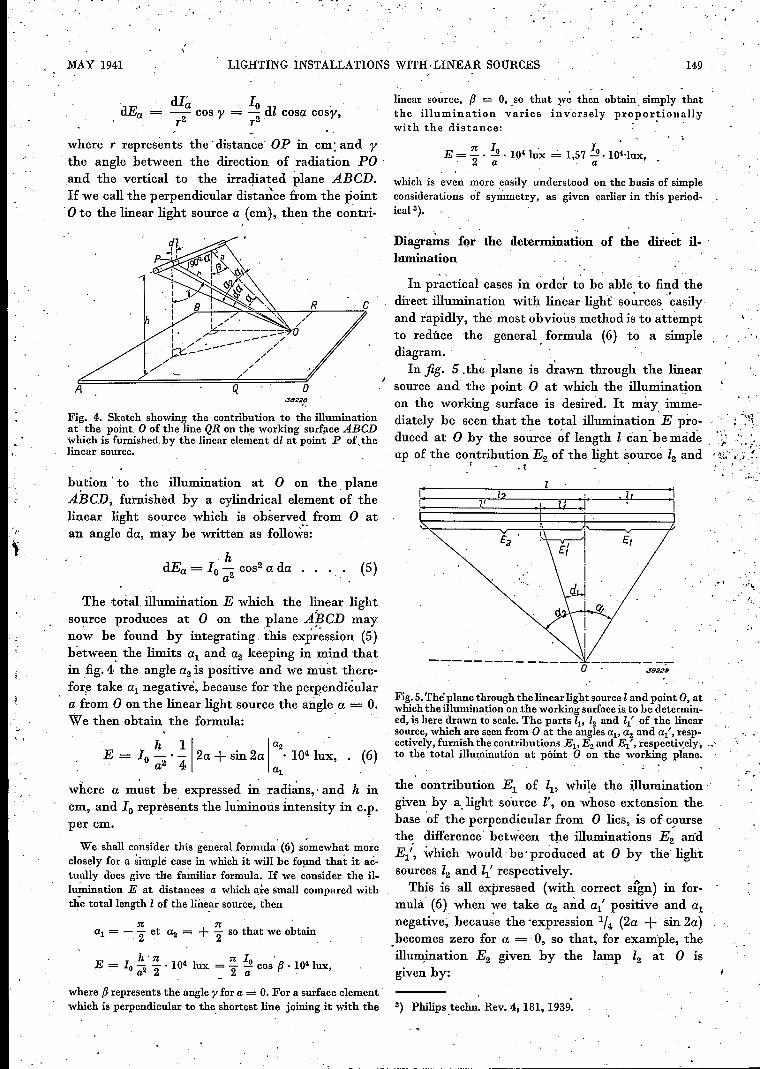
Fig. 4. Sketch showing the contribution to the illuminationat' the point 0 of the line QR on the working surface ABeDwhich is furnished by the linear element dl at point P of'thelinear source.
hl~tion . to the illumination at 0 on the planeABeD, furnished by a cylindrical element of thelinear light source, which is observed from 0 atan angle da, may he written as folloW:s:
hdEa = 10 - cos" a da
a2
The total illumination E which the linear lightsource produces at 0 on the plane ApeD maynow be found by integrating this expression (5)hetween the limits al and a2 keeping in mind thatin fig. 4 the angle a2 is positive and we must there-fore take al negative, because for the perpendiculara from 0 on the linear light source the angle a = O.We then obtain the formula: '
"·,1
h 11 1a2 .E = 10 _. - 2a + sin2a . 1041ux, . (6)a2 4 al
where a must he expressed in r'adians,> and h incm, and 10 represents the luminous intensity in c.p.per cm.
We shall consider this general formula (6) somewhat moreclosely for a simple case in which it will be found that it ac-tually does give the fa~ar formula. If we consider the il-lumination E at distances a which qre small compared withthe totallength 1 of the line,ar source, then
al = - ~ et a2 = + ~ so that we obtain
h'n nl'E = 10 - -.104 lux = - .J! cos f3 • 104lux,a2 2 ~ 2 a '
linear source, f3 = 0, ,so that ~ve then obtain, simply thatthe illumination varies î nve r sely propor~ionall,ywith the distance:
n 10 4' 10'E = - . - . 10 lux = 1,57 - . 104·lux,2 a a
which is even more easily understood on the basis of simpleconsiderations of symmetry, as given earlier in thi~ period-icnl ê).
Diagrams for the determination of the direct Il-, lumination
In practical cases in order t~ be able to find thedirect illumination with linear light sources '~asilyand rapidly, the most obvious method is to attemptto reduce the general. formula (6) to a simplediagram. 'In fig. 5.,the plane is iliawn through the linear
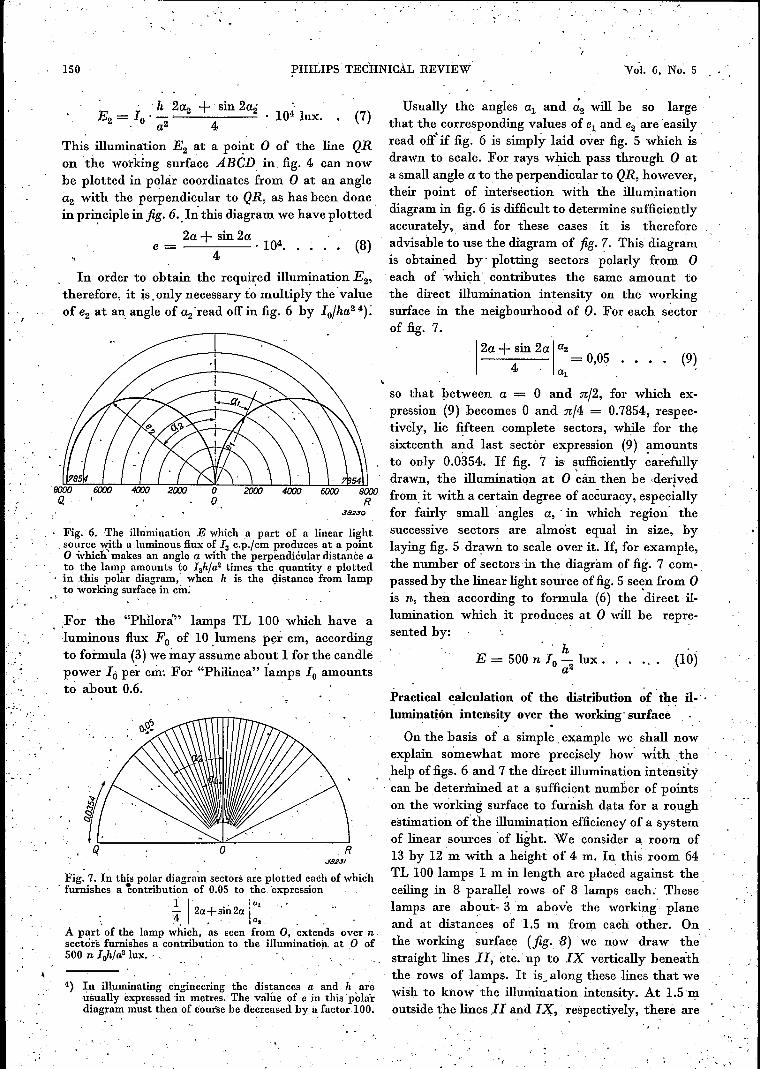
source and the point 0 at which the ilhiminationon the working surface is desired. It may imme-diately be seen that the total illumination E pro- - " : '~'\duced at 0 by the source ~f length I can -be madeup of the contribution E2' of the light source l2 and
. r.. ~ .'
I'" "'_ •.
;.. ~..-,' .~I ,!~~."'~'':.'
,I
(5)
-""
J8229
Fig. 5.Thé plane through the linear light source I and point 0, atwhich the illumination on the working surface is.to be determin-ed, is here drawn to scale. The parts ~, l2 and l{ of the linearsource, which are seen from 0 at the angles al' a2 and al" resp-ectively, furnish the contributions El' E2 and E{, respectively, -_'to the total îllumination at point Q on the working plane.
the contribution El of ~, while the illumination'given by a. light source I', on whose extension thebase of the perpendicular from 0 lies, is of c~lUrsethe difference' between the illuminations E2 andEl" which would -be'produced at 0 by theJightsources 12 and ~' respectively.This is all expressed (with COrrect sign) in for-
mula (6) when we take a2 and al' positive and alnegative, becau~e the 'expression 1/4 (2a + sin 2a)_becomes zero for a = 0, so that, for example, theillumination E2 given by the lamp l2 at 0 isgiven by:
where f3 represents the angle y for a = O.For a surface element'which is perpendicular to the shortest line joining it with the 3) Philips ,technoRev. 4, 181, 1939.
(7)Usually the angles al and a2 will he so large
that the corresponding values of el and e2 are easilyread o:!f'if fig. 6 is simply laid over fig. 5 which is 'drawn to scale. For rays which pass through 0 ata small angle a tothe perpendicular to QR, however,their point of intersectien with the illuminationdiagram in fig. 6 is difficult to determine sufficientlyaccurately, and for these cases it is thereforeadvisable to use the diagram of fig. 7. This diagramis obtained by' plotting sectors polarly from 0each of 'whiçh', contributes the same amount tothe direct illumination intensity on the workingsurface in the neigbourhood of O. For each sectorof fig. 7.
150 PHILlPS TEé'HNICÀL REVIEW
E _ I .'_h 2a2 + sin 2ai104 lux.
2 "". 0 a2 4
This illumination E2 at a point 0 of the line QRon the working surface ABeD in, fig. 4 can nowbe plotted in polar coordinates from 0 at an anglea2 with the perpendicular to QR, as has been donein pr~ciple in fig. 6.,I:n:this diagram we have plotted'
2a + sin 2a 'e = 4 . 104• • • • • (8)
In order to obtain the required illumination E2'therefore, it is, only necessary to multiply the' valueof e2· at an, angle of a2 'read off in fig. 6 by Io/ha2 4):
J82JO
Fig. 6. The ilhÎmination E which a part of a linear lightsource with aluminous flux of la c.p.fcm produces at a pointo which' makes an angle a with the perpendiéular distance ato the lamp amounts to Iahfa2 times the quantity e plottedin .this polar diagram, when h is the distance from lampto working surface in cm:
.For the "Philorá" lamps TL 100 which have aluminous flux Fo of 10 .lumens per cm, accordingto formula (3) we may assume about 1 for the candlepower Ió per cm. For "Philinea" Iamps 10 amountsto about 0.6.
-Ór ; ,
.':
J92JI
Fig. 7. In this polar diagram sectors are plotted each of which, furnishes a 'bontribution of O~OSto the<expression
,1 1'2 . 2 la.~ a:-sm a a, , '
A part of the lamp which, as seen from 0, extends over n .sectors furnishes a contribution to the ifluminution. at 0 of500 n Irft!a2 lux. ' . ,
4) In Illuminating engineering the distances a and hareusually expressed in metres. The value of e in this 'polardiagram must then of course be de~reased by a factor 100.
1
2a + sin 2a Iaa4 = 0,05 .••.
al(9)
so that petween a = 0 and n/2, for which ex-pression (9) becomes 0 and n/4 = 0.7854, respec-tively, lie fifteen complete sectors, while for thesixteenth and last sectór expression (9) amountsto only 0.0354. If fig. 7, is sufficiently carefully'drawn, the illumination at 0 ~án then he -derived
, . .from, it with a certain degree of accuracy, especiallyfor fairly small 'angles a,' in which region' thesuccessive sectors are almost equal in size, bylaying fig. 5 drawn to scale over it. If, for example,the number of sectors in the diagram of fig. 7 com-passed by the linear light source of fig. 5 se~n from 0is n, then according to formula (6) the direct il-lumination which it produces at 0 will be repre-sented by:
, , h .E = 500 n 10 _ lux .
a2(10)
Practical calculation of the distribution of the Il-lnminatión intensity over the working' surface
, "On the basis of a simple, example we shall now
explain somewhat more precisely how' with thehelp of figs. 6 and 7 the direct illumination intensitycan he deterrnined at a sufficient number of pointson the working surface to furnish data for a roughestimation o{the illumination efficiency of a systemof linear sources of light. We consider a room of13 by 12 m with a height of 4 m. In this room 64TL 100 lamps 1 m in length are placed against the,ceiling in 8 parallel rows of 8 lamps each. Theselamps are ab()Ut- 3 m above the working' planeand at distances of 1.5 m from each other. Onthe working surface (fig. B) we now draw thestraight lines 11, etc. up to IX vertically beneaththe rows of lamps. It is, along these lines that wewish to know-the illumination intensity. At 1.5 moutside ~he lines JI and nç, respectively, there are
MAY 1941 LIGHTING INSTALLATIONS WITH LINEAR.SOURCES
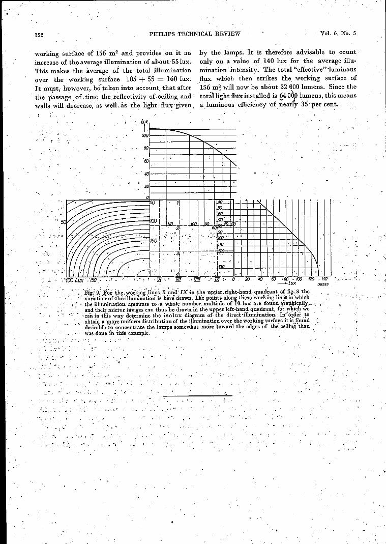
IX in the upper right-hand quadrant we have nowin fig.' 9 indicated the variation of the direct il-lumination: From this variation, the points can'immediately he found at which the direct illumi-nation amounts to a whole numher multiple of10 lux. The mirror images of these points in'th~ ,,quadrant of the working surface lying to the ,leftahove in fig. 9 can thus he indicated withoutdifficulty, and the lines may .be drawn throughthem indicating equ~l direct illuminations, whichgive us the so-called isolux diagram for theupper left-hand quadrant of the working surface.Although the direct illumination in the middle of. the room döes not ' vary rapidly, even when thelamps are regulàrly spaced it falls off rapidly nearthe walls, and in the direction of the axes of the-Iamps it even falls to less than -t; of its value in'the middle of the room, as will be clear from fig. 9. 'If the greatest possible uniformity in ~ght dis-tibrution over the whole working surface is desired,,therefore, the ,light sources' should he more closelyspaced along the edges of the ceiling' than hás 'heim done in' tliis example. '. If the luminous, efficiency of a system' is desiredthe total light f'Iu x which strikes the workingsurface should he determined, hecause theluminousefficiency is equal to this quantity divided hythe luminous flux installed. From the illumination
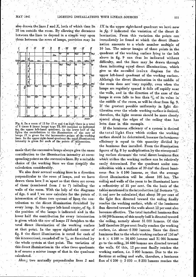
made that the successive lamps always give the same figures. of fig. 8 hy multiplication by the cörre~pond:contribution to the illumination intensity at corre- ing surface elements' the total, direct luminous fluxspondingpoints on th,e successivelines. By a suitahle whichstrikes the working surface can he relativelychoice of the working lines we thus simplify the easily determined. for the quadrant under con-calculation con~iderahly., ' ' siderátión with a surface óf 39 cm2 the direct lu~i-We also draw several, working lines in a direction nous flux is 4100 lumens, so" that the average
'perpendicular to the rows of lamps, and we have direct illumination will he ahout lOS, lux. Thedrawn them here 2 m apart so that there are seven ceiling and walls of the room to he illuminated haveof them' (numhered from 1 to 7) including the a reflectivity of 35 per: cent. On the hasis of thewalls of the room. With the help of the diagrams 'tahles mentioned in the introduetion (cf. footnote 1)),
. . . .' Ioffigs. 6 and 7,we now calculate for the points of . it can now he calculated. that about 20 per cent ofintersection of these two systems 0.£ IWe,§.the con- . the light flux directed toward the ceiling finallytrihution to the direct illumination furnished by reach~s the working surface, while of the luminousevery lamp. In the upper left-hand c,orner, of fig. 8 flux direçted toward the ,walls about 12 per cent alsothe position or: the lamps is indicated' ~~d' in the becomes effective. The total installed luminous fluxlower half the contribution ,for every intersection is 64 goo lumens; of this nearly half is directed towardis given which die row of lamps II furnishes to the the' ceiling, namely ahout 31000 lumens. Of thistotal direct illuminatioh of the working surface half therefore 20 per cent finally reaches t}leworking'at that point. In the upper rightJlaiid. corner of 'surface,' i.e. about- 6 200 lumen's. Since the directfig. 8 the direct illumination is noted for each of luminous flux to the wholeworking surface of 156m2
ttie intersections, rounded off to l/~,as furnished hy is 4 X 4 100 = 16.400 Iumens and 31 000 lumensthe whole system at that point. The variation of go to the ceiling,.16 600 lumens are ,directed towardthis direct Illutnination in the other three quadrants the walls. Of this, 12 per cent flnally, reaches theis of course a mirror image of that in the quadrant working surface, i.e. 2 000 lumens. Due to the re-'calculated. ' . flections at ceiling and walls, therefore, a luminousAlon,j two mutually perpendicular lines 2 and flux of 6 200 + 2 000 -=. 8 200 lumens reaches the
' ..
also drawn the lines I and X, hoth of which thus lie25'.~m outside' the room.' By allowing' the distanceshetween the lines to depend in a sÎn?-PI~way uponthose hetween the rows of lamps, provision may he
J84030
Fig. 8. In a room of 12 by 13m and 4 m high 'there is a totalof B times 8 linear lamps type TL 100 installed as indicatedfor. the upper left-hand _quadrant. In the lower half of theIlgtue the contrlbution to the illumination of' the row oflamps 11. is given for the' intersection points of the workinglines, In the upper right-hand quadrant the t9$.aL~lluminationintensity is given for each of the points of iIii~rsection. _
ot:, -I.l
it'"
151
_,
"
r:,'!.•,
•. "
152 PHILlPS TECHNICAL REVIEW .va. 6, No. 5
working surface of 156 m2 and provides on it anincrease of the average illumination of ahoutSf lux ..This makes the average of the total' illuminationover the working surface 105 + 5.5= 160 lux.It m~st,· however" be taken into account. that afterthe passage. of. time the. reflectivity of. ceiling and"walls will decrease, as weIL as the light flu~' given.
by the lamps. It is therefor~ advisable to countonly on a value of 140 lux for the average illu-mination intensity. The total "effective"'luminous..flux which then strikes the working surface of156 m~ will now be about 22 000 lumens. Since the
" ' ,~ "
totallight flux inst.alIed is ~4OOp lu~ens, this meansa)uminous efficiency 'of nearly 35·per cent. "
• t ••
.' '!_ ,.,80,1;-. --+--+-+ .........~.1'0<:<---I <,
.... ~,I".' i:-:-'·3}·-;-~-:-~~ ,I". f\. I' I I. 1; i ~ 1 I ' lw'
: • , ;.---:i <' 1. . r:A!' '_j' 1,.-: . .. ~I .., '."-. -.• -1-. 1-l--l-1-l--l-1-l--+--'I-+--l-I.. . .__ .L-.L:..J. __ .::t.l-. ._. __,_i_,_I_ •L- . L- '• .1..--1- I_~ I,~ L_ ~~.._,I._
'.'100 Lux .'150· ..r , ( ;'.- ~,Jl[. '.' JlII ., JlJD. ,'IX .~- 0 20, 40 60 ··80 100 120,140, ' _.. Lux J8233 ,
• :'. 'Fi~;; 9:'F~rthe.'l'órking)~è~. 2 ~rid:JX 4t .the upper,righ1;-h~nd quad~ant \lf fig:B the. .. . .' v-arfaii~nofthè iihi'ÏÓiûátion'is hër€ drawn, The points alóng tliesè 'worki.ÎJ.gliri~sin'which
\:. , the illuniination amounts to .a whole number. multiple of IûIux are found grap¥c!llly,,-,, and their mirror images can thus be drawn in the upper left-hand quadrant, forwhich we.r- ... i:án in thls way determine the isolux diagram of the direct sIllumiriation, In! o\dèr to'" obtain a W0}:'euniform distribution of the illuminution ove.r the working surface it is.f..öund "
desirable to concentrate the lamps somewhat more 'toward the edges of the ceiling than,was done in ihis example, . ' ' ,
, ;
.. "'...... . .~ ...~ .'
. ..",,"
....~_:
-r,
.,' .... ' .. •. «i
... ,';
. "'1' ~. '"
......
.,'1 ..
r " ~,, .
"

MAY 1941
PREPARATION OF VITAMINE D
In the works of N.V. Philips-van Houten at Weesp the vitamine D isobtained from provitamine in this irradiating apparatus, which containsfour high-pressure mercury lamps each consuming 1·5 kW.
153


