TG410 User Manual - dynagen.com Files/MAN-0099... · User Guide 1 I ntr oduci 4 1 ... 4.5.1 Engine...
69
Manual Revision: 6.0.0 Min. FW Revision: 1.82.09 Date Released: 18/12/2017 © 2017 DynaGen Technologies Inc TG410 User Manual
Transcript of TG410 User Manual - dynagen.com Files/MAN-0099... · User Guide 1 I ntr oduci 4 1 ... 4.5.1 Engine...

Manual Revision: 6.0.0Min. FW Revision: 1.82.09Date Released: 18/12/2017
© 2017 DynaGen Technologies Inc
TG410 User Manual

TG410 User Manual
© 2017 DynaGen Technologies Inc
Table of Contents
User Guide
41 Introduction
............................................................................................................................................................................... 5Specifications 1.1
62 Installation
............................................................................................................................................................................... 7General Wiring Notes 2.1
............................................................................................................................................................................... 7Terminal Descriptions 2.2
............................................................................................................................................................................... 10Wiring Harnesses 2.3
............................................................................................................................................................................... 11Typical Wiring Diagram 2.4
............................................................................................................................................................................... 12Typical Wiring Diagram with RelayPak 2.5
............................................................................................................................................................................... 13Wiring Considerations 2.6
....................................................................................................................................................................... 13Remote Start Contact (Start/Stop)2.6.1
....................................................................................................................................................................... 13Emergency Stop Wiring2.6.2
....................................................................................................................................................................... 14Universal Sensor2.6.3
....................................................................................................................................................................... 15CAN Bus Wiring2.6.4
....................................................................................................................................................................... 17Modbus Wiring2.6.5
....................................................................................................................................................................... 18Current Transformers2.6.6
....................................................................................................................................................................... 20RelayPak (Optional)2.6.7
223 Using the Controller
............................................................................................................................................................................... 23Modes, Starting and Stopping 3.1
....................................................................................................................................................................... 24Cranking Behaviour3.1.1
............................................................................................................................................................................... 24Using Cooldown Mode 3.2
............................................................................................................................................................................... 24Warnings 3.3
............................................................................................................................................................................... 25Failures 3.4
............................................................................................................................................................................... 25Event Log 3.5
274 Settings
............................................................................................................................................................................... 27Operator Setup 4.1
............................................................................................................................................................................... 29Switched Inputs 4.2
....................................................................................................................................................................... 31Configurable Inputs4.2.1
............................................................................................................................................................................... 31Switched Outputs 4.3
....................................................................................................................................................................... 34Group Outputs4.3.1
....................................................................................................................................................................... 34Pull and Hold Coil4.3.2
............................................................................................................................................................................... 35Sensors 4.4
....................................................................................................................................................................... 35Engine Temperature4.4.1
....................................................................................................................................................................... 36Oil Pressure4.4.2
....................................................................................................................................................................... 37Fuel Level4.4.3
....................................................................................................................................................................... 37Engine Speed4.4.4

TG410 User Manual
© 2017 DynaGen Technologies Inc
.......................................................................................................................................................................... 39Front Panel Speed Control
....................................................................................................................................................................... 40Battery Level4.4.5
....................................................................................................................................................................... 42Auxiliary Sensors4.4.6
.......................................................................................................................................................................... 46Fault Monitor Example
.......................................................................................................................................................................... 47Start on Low Example
.......................................................................................................................................................................... 48Output on High Example
.......................................................................................................................................................................... 49Sensor as a Switch
....................................................................................................................................................................... 49Custom Sensor Tables4.4.7
............................................................................................................................................................................... 50Timers 4.5
....................................................................................................................................................................... 50Engine Logic4.5.1
.......................................................................................................................................................................... 51Preheat Mode
.......................................................................................................................................................................... 51False Restart
.......................................................................................................................................................................... 52OFF Button Function
.......................................................................................................................................................................... 53Idle
............................................................................................................................................................................ 53Warmup Idle
............................................................................................................................................................................ 54Idle Inhibit
....................................................................................................................................................................... 54Schedulers4.5.2
.......................................................................................................................................................................... 54Exerciser
.......................................................................................................................................................................... 56Weekly Scheduler
.......................................................................................................................................................................... 56Long Time Run
....................................................................................................................................................................... 56Maintenance4.5.3
............................................................................................................................................................................... 57AC Monitor 4.6
....................................................................................................................................................................... 57Generator Voltage4.6.1
.......................................................................................................................................................................... 59AC Voltage Select
....................................................................................................................................................................... 59Generator Frequency4.6.2
.......................................................................................................................................................................... 60RPM / Frequency Select
....................................................................................................................................................................... 61Generator Current4.6.3
.......................................................................................................................................................................... 62Basic Alarms
.......................................................................................................................................................................... 62IDMT
.......................................................................................................................................................................... 63Load Imbalance
.......................................................................................................................................................................... 64Dummy Load
.......................................................................................................................................................................... 64EPS Supplying Load
............................................................................................................................................................................... 64Communications 4.7
....................................................................................................................................................................... 64CAN Bus (J1939)4.7.1
....................................................................................................................................................................... 66MOD Bus (RS485)4.7.2
............................................................................................................................................................................... 66Other Config 4.8
....................................................................................................................................................................... 66Password4.8.1
....................................................................................................................................................................... 66Settings Name4.8.2
....................................................................................................................................................................... 67Process Control4.8.3
685 Troubleshooting

3
© 2017 DynaGen Technologies IncTOUGH Series Manual
User Guide

Introduction 4
© 2017 DynaGen Technologies IncTOUGH Series Manual
1 Introduction
The TOUGH series controllers are designed to provide complete control, protection, AC metering, and engine instrumentation forboth standard and electronic engines. The module is easily configured using either the front panel buttons or our RapidCoreConfiguration software. TOUGH Series controllers are ideally suited for severe duty applications where reliability is critical such asmobile and stationary generators.
Features and Functions:
· 5 Year Warranty· SAE J1939 CAN Bus Protocol· RPM via J1939, Magnetic Pickup, or Generator· Speed control offset for electronic engines· Autostart on low battery and other sensors· Trim feature for AC monitoring and sensors· Maintenance counter· Exerciser Clock· 150 Event Log· Conformally coated for protection against moisture
· Gasket for water ingress protection resistance· Free RapidCore Configuration Software· Fast and rugged installation clips· Passcode protected· Automatic shutdowns and warnings· Manual and Remote start· Momentary Start / Stop inputs· Pre-heat and many other configurable timers· Accepts common senders (VDO, Datcon, S&W)· Custom senders configurable with RapidCore
Configuration software
Displays:
· Engine Temperature· Oil Pressure· Fuel Level
· Engine Speed· AC Metering· Battery Voltage
· Real Time Clock· Engine Hours· Time to Maintenance
· J1939 DTCs + Custom Text· Custom Senders· Warnings and Failures
Feature Included
DPF / DEF Ready
J1939 CAN Bus
Isolated RS485 Modbus
Magnetic Pickup Input
150 Event Log
Clock / Exerciser
Generator Voltage Metering Single or 3-Phase
Generator Current Metering (with IDMT and Load Imbalance features) Single or 3-Phase
Configurable Switched Inputs 5
Resistive Sensors (1 High Ohm, 1 Low Ohm) 2
Universal Sensor (Resistive, 0-5V, 4-20mA) 2
5V Sensor Output for Electronic Sensors
Configurable Switched Outputs 6

Introduction 5
© 2017 DynaGen Technologies IncTOUGH Series Manual
1.1 SpecificationsThe TOUGH Series controllers were rigorously tested to ensure durability, reliability and functionality. The following specificationsare a brief summary of the standards to which the controller has been tested. For complete details on the testing performed pleasecontact DYNAGEN.
Testing Specifications
Specification Rating
Electrical Transients SAE1113-11
Thermal Shock and Cycling SAE1455
Vibration Profiles SAE1455
Electric Static Discharge SAE1113-13
UL UL 6200 recognized component. Consult factory
for UL conditions of acceptability.
Physical Specifications
Specification Rating
Operating Temperature -40 to +158°F (-40 to +70°C)
LCD Viewing Temperature -4 to +158°F (-20 to +70°C )(Optional heater available, call factory)
WeightWeight w/ RelayPak
0.83lb (0.38kg)1.32lb (0.60kg)
Dimensions - controller (no gasket)- controller w/ gasket- controller w/ gasket and RelayPak
4.17" x 6.50" x 1.38" (10.59cm x 16.51cm x 3.51cm)4.41" x 6.79" x 1.38" (11.20cm x 17.25cm x 3.51cm)4.41" x 6.79" x 3.33" (11.20cm x 17.25cm x 8.46cm)
Electrical Specifications
Specification Rating
Operating Voltage 5.5 ~ 36 VDC
Standby Current 60mA @ 12V38mA @ 24V
Switched Inputs +Battery, Ground, Open, Closed
Switched Outputs +Battery @ 1A Max
Low Resistance Sensors 0 ~ 750Ohm
High Resistance Sensors 0 ~ 7,500Ohm
Universal Sensors 0 ~ 750Ohm, 0 ~ 7,500Ohm, 0 ~ 5 VDC, 4 ~ 20mA
Magnetic Pickup 10 ~ 10,000Hz at 1 ~ 50 VAC
AC Voltage (Line-To-Line) 50 ~ 600 VAC True RMS, Accuracy: 2% Full Scale. Do not connect more than 600VAC to the controller. Damagemay result.
AC Current 0 ~ 5A (Current Transformer), Accuracy: 1% Full Scale
Communications SAE J1939 (Tier II, III, IV)Isolated RS485 (Slave Modbus RTU)
External Sensor Power TG410 only: 5 VDC at a max load of 200mA

Installation 6
© 2017 DynaGen Technologies IncTOUGH Series Manual
2 Installation
Generator systems contain high voltage circuitry and precautions to protect against electrical shock should be taken. Failing topower down and lock out equipment can cause damage, injury or death.
WARNING: Wiring of this controller should be performed by qualified electricians only.
The following general electrical safety precaution should be followed:
· Do a thorough inspection of the area before performing any maintenance.
· Keep fluids away from electrical equipment.
· Unplug connectors by pulling on the plug and not the cord.
· Use fuses where appropriate.
· Ensure all equipment is properly grounded.
· Provide support to wires to prevent stress on terminals.
To ensure proper and safe operation, caution must be taken at the installation site to make sure it is free from excessive moisture,fluctuating temperature, dust and corrosive materials. Choose a mounting surface with the least amount of vibration and not morethan 0.125" (3.175mm) thick.
1) Choose a suitable mounting location based on the criteria above.
2) Create a rectangular cutout in the panel that is minimum 3.9" (99mm) high and 6.2" (158mm) wide.
3) Place the controller into the panel cutout so that the LCD screen and buttons are facing out.
4) Place the mounting clips into the designated slots on the top and bottom of the controller.
5) Tighten the screws on the clips until the controller is snug against the panel. Do not over tighten, the bottom of thescrews should angle very slightly away from the controller.
6) If applicable, snap the RelayPak (RP100) to the back of the controller. Place one side of the RP100's tabs into the slot onthe back of the controller and, without pushing on the relays, snap the other tab into place.
TE Series Cutout (Not To Scale)

Installation 7
© 2017 DynaGen Technologies IncTOUGH Series Manual
2.1 General Wiring NotesThe following important wiring guidelines should be followed:
1. Use a minimum of 18AWG wire for all connections. 2. Battery + and Battery - connections on the controller should be run directly to the positive and negative terminals on the
battery to prevent voltage drops from negatively impacting the controller.
3. Limit the wire length to 20ft (6.1m) to any I/O on the controller (e.g. Switched Input, Switched Outputs, AC Sensing, andAnalog Inputs).
4. It is good practice to run the AC voltage sensing wiring to the controller in a separate conduit from the AC current sensingwiring. If the AC voltage is especially noisy (e.g. variable frequency drives) then they MUST be run separately.
5. The TOUGH Series contains a TVS to protect the I/O and internals from a transient on the main battery (the battery thecontroller is powered from). If you have I/O connected to other batteries or power supplies those I/O must contain their ownvoltage transient protection. Otherwise the I/O and/or controller can be damaged if the transient exceeds the maximum ratedvoltage of the I/O. A device that provides this kind of protection is know as a TVS or a varistor.
6. Fusinga. A fuse should be placed inline with the battery + wire going to the controller power. A 10A fuse is suggested.b. The AC Voltage A, B, and C lines should be fused near the source of AC voltage with a 1A fuse. This protects personnel if
any of these lines become disconnected and short or touch items or personnel.c. If using the RelayPak the power going to the relay commons should be fused.
7. For noisy environments some guidelines are:a. Replace speed sensing wire with twisted pair from the sensor to the controller.b. Consider using isolated sensors (i.e. two terminal) and use twisted pair wiring to connect from engine to controller.
The following enclosure guidelines should be followed:
1. It is recommended to use vibration mounts.2. For outdoor applications, it is recommended to use a sealed enclosure.
2.2 Terminal DescriptionsMain Connector (J4)
Terminal Name Description
J4-1 +Battery Provides power to the controller from the battery
J4-2 +Battery Provides power to the controller from the battery
J4-3 Ground Provides ground return for the controller
J4-4 Ground Provides ground return for the controller
J4-5 Switched Input A Configurable to detect +Battery, Ground, or Open
J4-6 Switched Input B Configurable to detect +Battery, Ground, or Open
J4-7 Switched Input C Configurable to detect +Battery, Ground, or Open
J4-8 Switched Output A Outputs +Battery voltage when active (Max Current: 1A)
J4-9 Switched Output C Outputs +Battery voltage when active (Max Current: 1A)
J4-10 Switched Output B Outputs +Battery voltage when active (Max Current: 1A)
J4-11 Sensor Ground Provides ground return for 2-wire (isolated) sensors
J4-12 Sensor Input A High impedance sensor input (0 - 7,500Ohm)
J4-13 Sensor Input B Low impedance sensor input (0 - 750Ohm)
J4-14 Sensor Input C Universal sensor input (0 - 750Ohm, 0 - 7,500Ohm, 0 - 5 VDC, 4 - 20mA). See Universal Sensor section for more information.

Installation 8
© 2017 DynaGen Technologies IncTOUGH Series Manual
Expansion Connector (J3)
Terminal Name Description
J3-1 Switched Input D Configurable to detect +Battery, Ground, or Open
J3-2 Switched Input E Configurable to detect +Battery, Ground, or Open
J3-3 Switched Output D Outputs +Battery voltage when active (Max Current: 1A)
J3-4 Switched Output E Outputs +Battery voltage when active (Max Current: 1A)
J3-5 Switched Output F Outputs +Battery voltage when active (Max Current: 1A)
J3-6 Sensor 5V Provides 5 VDC for electronics sensors.
J3-7 Sensor Ground Provides ground return for 2-wire sensors
J3-8 Sensor Input D Universal sensor input (0 - 750Ohm, 0 - 7,500Ohm, 0 - 5 VDC, 4 - 20mA) See Universal Sensor section for more information.

Installation 9
© 2017 DynaGen Technologies IncTOUGH Series Manual
Communications Connector (J6)
Terminal Name Description
J6-1 RS485 + (Non-Inverting) Non-Inverting communications line for Modbus (RS485). This is also often knownas A.
J6-2 RS485 - (Inverting) Inverting communications line for Modbus (RS485). This is also often known as B.
J6-3 No Connection No Connection
J6-4 CAN-H Communications line for CAN Bus (J1939)
J6-5 CAN-L
J6-6 CAN-Shield Connect the shield of the twisted pair cable to this terminal
J6-7 Speed Sensing A Connect to a magnetic pickup, tachometer, or a flywheel alternator. Not polaritysensitive and not required if using AC voltage terminals for speed sensing.
J6-8 Speed Sensing B Connect to a magnetic pickup, tachometer, or a flywheel alternator. Not polaritysensitive and not required if using AC voltage terminals for speed sensing.
J6-9 No Connection No Connection
J6-10 RS485-Common Common line for Modbus (RS485)
Generator AC Voltage (J7)
Terminal Name Description
J7-1 Phase A Connect to Phase A of the generator
J7-2 Phase B Connect to Phase B of the generator
J7-3 Phase C Connect to Phase C of the generator
J7-4 Neutral Connect to neutral.
Generator AC Current (J5)
Terminal Name Description
J5-1 Phase A Connect to current transformer for Phase A of the generator
J5-2 Phase B Connect to current transformer for Phase B of the generator
J5-3 Phase C Connect to current transformer for Phase C of the generator
J5-4 CT Common Connect to the commons of the current transformers

Installation 10
© 2017 DynaGen Technologies IncTOUGH Series Manual
2.3 Wiring Harnesses

Installation 11
© 2017 DynaGen Technologies IncTOUGH Series Manual
2.4 Typical Wiring Diagram
Installation 12
© 2017 DynaGen Technologies IncTOUGH Series Manual
2.5 Typical Wiring Diagram with RelayPak
Installation 13
© 2017 DynaGen Technologies IncTOUGH Series Manual
2.6 Wiring ConsiderationsThe following sections are meant to describe certain wiring configurations and are for illustrative purposes only. Not all applicationsare the same. Please ensure you modify these examples to fit your unique system requirements.
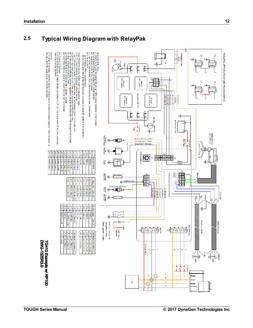
2.6.1 Remote Start Contact (Start/Stop)
As of Firmware version 1.60 the start/stop is factory defaulted to switch input B (changeable) and the trigger factory defaulted toClose +BAT. For older firmware versions you must set Start/Stop to Switched Input B or as desired and set the trigger mode toClose +BAT. The trigger can be set to any of four options but Close +BAT gives the best immunity to noise.
For runs over 20ft (6.1m) especially in noisy environments DYNAGEN recommends connecting the Start/Stop to an external relay. The relay needs to be located as close to the controller as possible.
2.6.2 Emergency Stop Wiring
If Emergency Stop functionality is required, it is mandatory to install an external mushroom style switch wired in series with thefuel or ignition supply to ensure reliable and immediate shutdown upon activation.
Shown below is an example wiring diagram of a double pull, single throw switch being used to activate the e-stop input and cutpower to the fuel solenoid. In this configuration, the e-stop is activated when there is an open circuit to the switched input andinactive when the input detects +Battery voltage.

Installation 14
© 2017 DynaGen Technologies IncTOUGH Series Manual
2.6.3 Universal Sensor
Universal Sensors have the ability to be configured to detect different sender types (0 - 750Ohm, 0 - 7,500Ohm, 0 - 5 VDC, 4 -20mA). The examples shown below are advanced applications of the universal sensor.
NOTE: Custom Sensor tables are required for the universal sender to work with these examples. See the CustomSender Table section for more information.
Example #1: The following example shows the correct way for wiring a 4-20mA sensor. The 240Ohm resistor is required totransform the 4-20mA current into the 0-5V voltage range required by the controller.
4-20mA Wiring Example
Example #2: Sometimes it is required to measure voltages outside the 0-5V range allowed by the controller. To do this you mustuse a voltage divider with appropriate scaling resistors. The equation to calculate the resistor values is as follows:
Vout = 5VVin = Maximum Voltage to ReadR1 = Common Resistor Value > 10kOhmR2 = Calculated Resistor Value (Select closest common resistor value)
The following diagram shows the typical wiring of a voltage divider. The resistors' values have been selected to allow the controllerto read up to 36V from an external battery bank.
0-36V Wiring Example
NOTE: A TVS (i.e. varistor) is required if the battery is different than the battery the controller is powered from. Thecontroller's TVS cannot protect the sensor input from transients in this case.

Installation 15
© 2017 DynaGen Technologies IncTOUGH Series Manual
2.6.4 CAN Bus Wiring
The following table outlines some items that must be taken into consideration when connecting to a CAN bus engine.
Consideration Description
Bus TerminationEach end of the bus must be terminated from CAN H to CAN L with 120Ohm +/- 10 Ohmresistors. The resistor must be able to handle at least 400mW of power dissipation.
Cable Selection
A twisted pair 120Ohm impedance cable is required for communications. For better protection ashielded twisted pair cable is recommended.
Examples are:1. Belden 9841 - Shielded cable with one twisted pair, 24AWG2. Belden 7895A - Shielded cable with two twisted pair, 20AWG
For short runs of 5 feet or less regular 18AWG wiring can often be run.
ShieldingIf using a shielded cable the shield must be connected to ground on one end of the bus only.This prevents loss of data from electromagnetic interference.
Termination at the ControllerThe twisted pair cable must terminate no farther than 6 inches from the controller's CAN (J1939)connector. Three inches is ideal.
Communications Wiring
It is common practice to use the fuel output to trigger the ECM key input to enable the ECM before cranking. For some ECMs tofunction, they must be powered/enabled for a certain period before cranking to allow time for the ECM to boot up. There are twoways to provide this time:
· Set a preheat time or increase the preheat time to allow longer time for the ECM to boot up before cranking. The fueloutput turns on at the start of preheat.
· Enable the Auto Power ECM setting in the Communications -> CAN Bus (J1939) menu will cause the fuel output to turn onin Auto mode and stay on.
ECM Wiring

Installation 16
© 2017 DynaGen Technologies IncTOUGH Series Manual

Installation 17
© 2017 DynaGen Technologies IncTOUGH Series Manual
2.6.5 Modbus Wiring
The following table outlines some items that must be taken into consideration when connecting up a Modbus system.
Consideration Description
Bus TerminationEach end of the bus must be terminated from A to B with 120Ohm +/- 10 Ohm resistors. Theresistor must be able to handle at least 400mW of power dissipation.
Cable Selection
Shielded twisted pair 120Ohm impedance cable is required for communications. Shield drainwire is NOT be used for the RS485 common. The cable must have one twisted pair for A and Band a seperate wire or twisted pair for common.
An example is Belden 7895A, a two twisted pair, 20AWG, where the second pair can be usedfor the RS485 common.
Distance (Power and Ground)
If running power and ground from the battery of your system to a remote device, use thefollowing guidelines for the gauge of the power and ground wires.
1. Up to 450ft (137.2m) - 22AWG2. Up to 700ft (213.4m) - 20AWG3. Up to 1125ft (342.9m) - 18AWG4. Up to 1800ft (548.6m) - 16AWG5. Up to 2800ft (853.4m) - 14AWG
Termination at the ControllerThe above cable must terminate no farther than 6 inches from the controller's RS485 (Modbus)connector. Three inches is ideal.
Refer to the Example wiring diagram for a wiring example.
Installation 18
© 2017 DynaGen Technologies IncTOUGH Series Manual
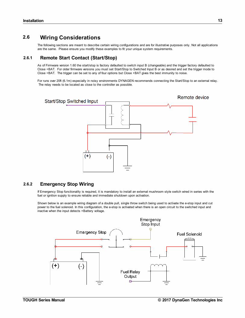
2.6.6 Current Transformers
When wiring current transformers into the system you must follow these considerations:
1. The maximum amperage allowed on the secondary is 5A. A 5:X ratio CT should be used where X is the maximumprimary amperage rating (e.g. 200A).
2. The CT power rating should be a minimum of 1VA.
3. The current transformer of each phase must be facing the same direction. See below.4. The CT Common connection must be connected to the black wire on each current transformer.5. The wires from the current transformers to the controller should be as short as possible.6. The CT wires should be run in a separate conduit from the AC voltage wires.
NOTE: If readings are unstable with the configuration shown below, attempt connecting the CT Common's black wireto the negative terminal of the battery. Ensure the connecting wire is as short as possible.

Installation 19
© 2017 DynaGen Technologies IncTOUGH Series Manual

Installation 20
© 2017 DynaGen Technologies IncTOUGH Series Manual
2.6.7 RelayPak (Optional)
Model Number: RP100-VM
The RelayPak is used to provide up to four built-in slave relays in a compact and easy to wire package. This allows the low currentoutputs of the controller to switch on high current relays on the RelayPak.
Note:The relayPak can be used to sense DC voltages up to 39 VDC using one of the Auxiliary Sensor Inputs on the controller. TheVM in RP100-VM refers to this voltage sensing capability. Refer to drawing DWG1552 under www.dynagen.ca/support. If thiscapability is used, the forth relay, Relay D, cannot be used.
Electrical Specifications
Specification Rating
Operating Voltage 12V / 24V
Output Pilot Duty Rating 5.83A Per Relay @ 12V
Output Resistive Rating 10A Continuous Per Relay @ 12V40A Momentary Per Relay @ 12V
Relay Style Automotive Cube
Standards
UL 6200 recognized component. Consultfactory for UL conditions of acceptability.
WARNING: You must use relays in the RelayPak that are suitable for the system voltage. Example: 12V relays in a12V system and 24V relays in a 24V system.

Installation 21
© 2017 DynaGen Technologies IncTOUGH Series Manual

Using the Controller 22
© 2017 DynaGen Technologies IncTOUGH Series Manual
3 Using the Controller
The LCD display is the primary source of information from the controller. It allows you to view/change settings and monitor thestatus of sensors and other engine peripherals.
LCD Display
Using the Menu System
Task Description
Entering Menu When in the OFF mode, press the enter button to bring up the menu.
Navigating Menu Once in the menu, use the up and down arrows to navigate. Pressing enter will move you intothat menu.
Change a Setting Scroll to the desired value and press enter to select. A check mark should appear beside thatitem. Press enter again to save the setting and return to the previous screen.
Scroll Parameters When in Auto or Running mode, pressing the up and down arrows will scroll through theparameter pages.
Lock Screen When in Auto or Running mode, the screen can be locked to a certain parameter page bypressing Enter and unlocked by pressing Enter again.
Events History Once in the menu, select Events History to view the most recent controller event. Use the upand down arrows to navigate to other events. The controller can store up to 150 events. If morethan 150 events occur, the oldest event is deleted to make room for the next event.
Front Panel Items
Item Name Description
Off Button Used for turning off the engine or exiting out of Auto mode. This is notintended to function as an Emergency Stop as there are conditions in whichit will not shut down the engine. See the OFF Button Function section formore information.
Auto Button Used for placing the controller into AUTO mode . Once in AUTO mode, thecontroller waits for a start command to be received.
Run Button Used to start the engine manually. The Off button must be used to shutdown the engine if it has been started using the front panel.
Up Button Used for moving around in the menu, changing a setting's value, or changingthe currently displayed parameter page.
Enter Button Used for entering the menu system, accepting settings, or locking the LCDscreen when viewing parameters .
Down Button Used for moving around in the menu, changing a setting's value, or changingthe currently displayed parameter page .
Generator/Engine LED Green = Engine running with no issuesAmber = Engine running with warningsRed = Engine shut down on failure

Using the Controller 23
© 2017 DynaGen Technologies IncTOUGH Series Manual
3.1 Modes, Starting and StoppingThe following table describes the different operating modes of the controller:
Modes
Mode / State Description
OFF When in the OFF mode, the engine cannot be remotely started.
Auto When in the Auto mode, the engine waits to receive a start command.
Running When engine is Running, the controller monitors engine parameters and waits to receive a stopcommand.
Failure When a failure occurs, the controller shuts down the engine and displays the reason for failure.The unit must be reset using the front panel OFF button with the exception of Modbus.
Menu When in the menu mode, settings can be changed and the events history may be viewed.
The following table describes the different methods for starting a controller. Unless using the Manual Run method to start thecontroller, the controller must be in AUTO mode.
Starting Methods
Methods Description
Manual Run Pressing the Run button will start the engine. You must press the OFF button to shut down theengine.
Start / Stop Switched Input When this input is active the engine will start. When the input becomes inactive the engine willshut down.
Momentary Switched Inputs Switched inputs Momentary Start and Momentary Stop can be used for starting and stopping ofthe engine. Unlike other inputs, they only have to be activated for a short period of time.
Battery Recharge When the battery voltage drops below a certain level the engine will start and run for apredetermined amount of time.
Exerciser When the scheduled exerciser interval occurs the engine will start and run for a predeterminedamount of time.
Weekly Scheduler When a scheduled event occurs the engine will start and run for the programed amount of time.
Auxiliary Sensors When a properly configured Auxiliary sensor falls below / rises above a certain point the enginewill start as determined by the Auxiliary Sensors -> Mode Select settings.
Modbus Start When a certain command is sent to the controller over Modbus the engine will start. See theModbus Reference Manual for more information.
J1939 Start Start/stop command send over the J1939 CANbus. For example from the TR100 or a remotetelemetry device. The controller will display either "J1939 Run" or "J1939 Remote" as the reasonfor starting.
ECM Power On This is not a starting mode like the others. In AUTO mode if the Auto button is held for 3s thefuel output is turned on for 1 hour. "ECM Power On" will be displayed on the screen. Pressingand holding again within the hour will refresh for another hour. This feature can be used to turnon or activate equipment powered by the fuel output. Often this is used by a tech to power theECM on an electronic engine so a diagnostic tool can obtain information from the ECM.
WARNING: See the Using Cooldown Mode section for more information on how it affects starting and stopping.

Using the Controller 24
© 2017 DynaGen Technologies IncTOUGH Series Manual
3.1.1 Cranking Behaviour
Crank disconnect in only monitored at the beginning of cranking. If the engine is already running the starter motor (output set toCrank) may turn on briefly.
If the controller is programmed to use CAN J1939 or a magnetic pickup (sensor or alternator output) the controller will also monitorAC Voltage Phase A line for frequency as a backup or secondary means of crank disconnect. This occurs even if AC Voltagesensing is disabled in the settings.
The oil pressure is not used as a means of crank disconnect.
3.2 Using Cooldown ModeWhen the controller is configured to have a cooldown period (See Engine Logic section) for the engine, there is some specialfunctionality that must be considered.
The cooldown period is special in that during this time, it will accept a Start Command. This means if the engine is cooling downand a start command is received, the controller will be placed back into a running mode and will not shut down.
Example: The following is an example of how the cooldown functionality works.
1. Remote Start contacts close2. Engine starts and is in the running mode3. Remote Start contacts open4. Engine starts cooldown period5. User presses RUN button on the front panel6. Engine moves back into running mode and does not shut down7. Engine can now only be shut down by using the OFF button or Emergency Stop input
3.3 WarningsWarnings are conditions that alert the user to possible issues. These get enabled/disabled when you enable/disable varioussettings in the controller.
Notable warnings are given in the below table.

Using the Controller 25
© 2017 DynaGen Technologies IncTOUGH Series Manual
WarningName
Enabled Condition(s) Description
High FuelLevel
High Fuel Level not disabled (in Sensors > FuelLevel menu).
High Fuel Level warning. This is often used to indicate an overfueling condition where fuel could be overflowing from the fueltank.
LowEngineTemp
Low Engine Temp not disabled (in Sensors >Engine Temp. menu).
Low Engine Temperature warning. This is often used to indicate amalfunction of the engine block heater in stationary generatorapplications.
Low OilPressure
Switched input set to "Oil Pres. Warn" function.See Switched Inputs. Triggered if switched input isactive during the RUN mode.
Low oil pressure warning.
3.4 FailuresFailures are conditions that cause the controller to shutdown to prevent damage to the engine or generator. These getenabled/disabled when you enable/disable various settings in the controller.
Notable failures are given in the below table.
FailureName
Enabled Condition(s) Description
ECMCommunication Failure
Enabled if loss of ECM communication isenabled. See CAN Bus (J1939). J1939 feature.
If the controller has not received messages from the ECM for6s.
Exception* Always enabled. Occurs when there is an issue that the controller cannotrecover from. For example EMI can cause the microcontrollerto become in a bad state or a software bug could cause thecode to hang triggering the watchdog. In these cases thecontroller will reset and enter the failure state.
*The name is configurable so may not match what is here.
Failure ToStop
Disabled when ETS On Duration is set to 0seconds. Otherwise it is enabled. ETS shouldbe set to at least 2 to 3s otherwise this failuremay not occur. Engine Speed feature.
After ETS countdown is finished if the speed was greater than50RPM for the previous 2s then the controller triggers thisfailure.
LoadImbalance
See Load Imbalance. AC Current feature. Generator load imbalance. Excessive AC current on one ormore of the three phases.
Low AirPressure
Switched input set to "Air Pres. Fail" function.See Switched Inputs. Triggered if switched inputis active during starting.
Application specific.
Low CoolantLvl
Switched input set to "Cool. Lvl Fail" function.See Switched Inputs. Triggered if switched inputis active.
Low Coolant Level.
LowHydraulic
Switched input set to "Hyd Pres. Fail" function.See Switched Inputs. Triggered if switched inputis active during starting.
Refers to Low Hydraulic pressure usually. Application specific.
If Battle Mode (see Battle Mode in switched inputs) is active ('Battle Running' is displayed on the screen) the controller will notshutdown on a failure and no failure information will be displayed on the screen. If battle mode is switched off the controller willshutdown on any failure that occurred when battle mode was active.
3.5 Event LogThe event log contains the following events
Event Name Event Type Description
Using the Controller 26
© 2017 DynaGen Technologies IncTOUGH Series Manual
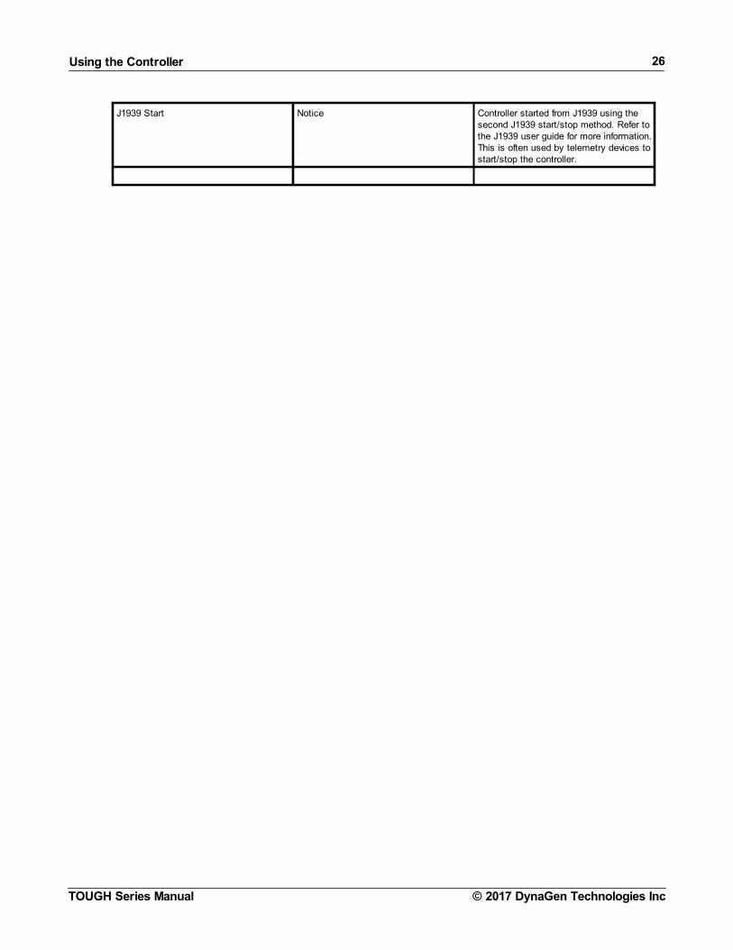
J1939 Start Notice Controller started from J1939 using thesecond J1939 start/stop method. Refer tothe J1939 user guide for more information.This is often used by telemetry devices tostart/stop the controller.

Settings 27
© 2017 DynaGen Technologies IncTOUGH Series Manual
4 Settings
The following section relates to settings that can be changed to alter the way the controller performs its functions. Read and reviewthese sections carefully to ensure your settings are set correctly for your engine.
4.1 Operator SetupThe following settings are used to change the way the user interacts with the controller. They are not password protected and canbe changed by anyone from the front panel.
Name Range Description
Lamp Test Function Performs a lamp test on the LEDs when selected.
Display > LCD Reverse Function Reverses the white and black pixels when selected.
Display > LCD Contrast 5 ~ 95% Changes the contrast of the LCD.
Display > Page Scroll 1 ~ 10 seconds Amount of time between each auto scroll of the parameterpages.
Display > Message Pop-Up 1 ~ 10 seconds Amount of time each message is displayed on the screenbefore displaying next message in the buffer.
Display > DPF/DEF Display Time 0 ~ 10 seconds See DPF/DEF aftertreatment in the J1939 Reference Manual formore information.
Display > LCD Backlight Timeout 10 ~ 600 seconds Amount of time the LCD Backlight stays on after button activitystops.
Display > Default Application Menu Tank Level / FloatApplicationWind MachineApplication
(configurable using RapidCore software only) Sets the frontpanel application menu. The application menu is the first menulisted in the menu system and is where end users go toconfigure the controller.
Display > Default Display Page Display Page 1Display Page 2Transducer Tank Page
(configurable using RapidCore software only)Set the page in run mode that will be displayed after the nobutton presses timeout is activated.
Display > Display Page 1Parameters > Display for Line 1Display for Line 2Display for Line 3Display for Line 4
Blank LineEngine SpeedBatteryAC FrequencyCurrent Run TimeEngine HoursOil PressureFuel LevelEngine CoolantTemperatureAmbient TemperatureTransducer Start/StopTemperature
(configurable using RapidCore software only)Two of the RUN mode scrolling pages can be customized. Upto four parameters (lines) per page can be shown.
If "Black Line" is set four two consecutive lines then those twolines are removed and all sequent lines are moved up. If onlyone page is desired then set all lines to "Blank Line" and thatpage will not be shown.
Current Run Time - The amount of time the engine has beenrunning since the last start condition.The following two options are meant to be displayed if "DefaultApplication Menu" is set to "Wind Machine Application":Ambient Temperature - This is the value of the Aux 5transducer which is expected to be set to temperature. Transducer Start/Stop Temperature - This is the "Start" and"Stop" setting in the Sensors > Auxiliary Sensor 5 menu.
Display > Display Page 2Parameters > Display for Line 1Display for Line 2Display for Line 3Display for Line 4
Date / Time > Date Change 1 ~ 31 days1 ~ 12 months2000 ~ 2099 years
Sets the date.
Date / Time > Time Change 0 ~ 23 hours0 ~ 59 minutes0 ~ 59 seconds
Sets the time.
Date / Time > Daylight Savings Enable ~ Disable Turns Daylight Savings Time on or off. This applies to NorthAmerica only. Disable for other locations.
Units > Temperature Unit °F or °C Selects the temperature display format.
Settings 28
© 2017 DynaGen Technologies IncTOUGH Series Manual
Name Range Description
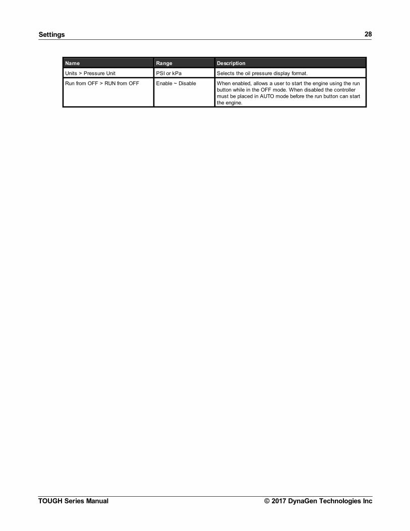
Units > Pressure Unit PSI or kPa Selects the oil pressure display format.
Run from OFF > RUN from OFF Enable ~ Disable When enabled, allows a user to start the engine using the runbutton while in the OFF mode. When disabled the controllermust be placed in AUTO mode before the run button can startthe engine.

Settings 29
© 2017 DynaGen Technologies IncTOUGH Series Manual
4.2 Switched InputsThe controller has switched inputs which cause the controller to perform a function when activated.
Switched I/O > Switched IN X:
Name Range Description
Function [Menu] See below. The function that the switched input performs when active.
Active Mode [Menu] See below. Determines the operating conditions under which the switched input can beactive. Multiple selections are allowed.
Trigger [Menu] See below. The state of the input determining if it is active or inactive.
Switched I/O > Switched IN X > Function:
Name Active Mode Description
Disabled N/A Input is disabled and has no function.
Start / Stop Auto, Running Starts the engine when active, stops the engine when deactivated. It isrecommended to set the Trigger mode to Close +BAT for better noisetolerance.
If Trigger mode is set to "Open" or "Close +BAT/GND" the start/stop inputwill act like a momentary input. A pulse of 2 to 4 seconds will startcontroller. Another pulse of 2 to 4 second duration is required to stop thecontroller. If the input is just turned off, the controller will continue to run.
Emergency Stop Global When active, shuts down the engine, displays Emergency Stop, andprevents leaving the OFF mode.
CAUTION !!! This should only be used for emergency stop indication on thecontroller. The installer must provide an independent means to shut downthe engine from the emergency stop button such as cutting off fuel. See thetypical wiring diagrams for an example on how to wire up the emergencystop.
Idle Mode Running See the Idle section under Engine Logic for more information.
Voltage Select 1 Auto Used for changing the system AC voltage configuration. See AC VoltageSelect for more information.
Voltage Select 2 Auto
Charger Fault (BatteryCharger Fault)
Global Controller displays 'Charger Fault' warning when active.
Mom. Start (MomentaryStart)
Auto Starts or stops the engine when momentarily active for at least 2seconds.These inputs allow the user to wire separate inputs for start andstop or to use a push button instead of a toggle switch.
Momentary stop will only stop the controller when the reason for start was"momentary start". It will not stop if the front panel run button was used tostart the engine.
Mom. Stop (MomentaryStop)
Running
Configurable Warning 1 Configurable Controller displays a warning or failure with configurable text* when active. Inthe case of the configurable failures a shutdown is also performed.
The RapidCore Configuration Software must be used to change the text.
Configurable Warning 2 Configurable
Configurable Failure 1 Configurable
Configurable Failure 2 Configurable
Configurable Failure 3 Configurable
Air Press. Fail (AirPressure Failure)
Cranking Controller displays 'Low Air Pressure' and shuts down engine when active.
Hyd Pres. Fail (LowHydraulic PressureFailure)
Cranking Controller displays 'Hydraulic Pressure Failure' and shuts down engine whenactive.
Oil Pres Warn (Low OilPressure Warning)
Running Controller displays 'Oil Pressure Warning' when active.

Settings 30
© 2017 DynaGen Technologies IncTOUGH Series Manual
Name Active Mode Description
Cool. Lvl Fail (LowCoolant Level Failure)
Global Controller displays 'Low Coolant Lvl' and shuts down engine when active.
High Fuel Warning Global Controller displays 'High Fuel Level' warning when active.
Lamp Test Global Controller performs lamp test when active. If the controller is in the FAILUREmode the LED will remain red. The only indication that the lamp test isactive is the LED indicator will alternate between the green and red colors.The LED goes back to it's original state when the switched input is no longeractive.
Fuel In Basin Global Controller displays 'Fuel In Basin' warning when active.
Battle Mode After Cranking Controller ignores all warnings and failures when active. Displays 'BattleRunning' when active. If a failure occurs during Battle Mode it is 'latched' andthe engine will shutdown on failure when the controller leaves Battle Mode.
Start Inhibit Global Controller ignores all start commands and the engine cannot start whenactive. Once Start Inhibit becomes inactive, starting is enabled again. If theengine is running, activating this input will shut down the engine.
RPM Switch (PrimaryRPM / 60Hz -Secondary RPM / 50HzSelect)
Auto Used for changing between Primary and Secondary RPM for an engine or50Hz / 60Hz for a generator. See RPM / Frequency Select for moreinformation.
ECM Preheat (ECMPreheat Signal)
Cranking (during thePreheat countdownonly)
Controls preheating using a switched input. See Switched Input in the Preheat Mode section.
Remote Reset Global Allows the controller to be reset from a failure mode. - Momentary action for 3 - 5s in FAILURE mode will place the controller inOFF mode. - Momentary action for 3 - 5s in OFF mode will place the controller in AUTOmode. - Momentary action for 3 - 5s in RUN mode will place the controller in AUTOmode. Cool-down is skipped.
NOTE: More than one Active Mode can be selected.
The active modes is only configurable if the Function menu is set to one of the configurable switched input functions. It is fixed for all other functions.
Switched I/O > Switched IN X > Trigger:
Name Description
Close +BAT Input is active when +Battery is present at the terminal.
Close GND Input is active when Ground is present at the terminal
Close +BAT/GND Input is active when either +Battery or Ground is present at the terminal.
Open Input is active when neither +Battery or Ground is present at the terminal.
NOTE: When running wires over long distances (over 20ft / 6.1m), it is recommended to use +BATTERY as the triggermethod.

Settings 31
© 2017 DynaGen Technologies IncTOUGH Series Manual
4.2.1 Configurable Inputs
These inputs are used to create custom warnings and failures. Using the RapidCore Configuration Software you can change thetext displayed when the warning or failure occurs. If you select one of these inputs without changing the text it will default to 'ConfigWarn X' and 'Config Fail X.'
There are also timers associated with the configurable inputs which can be found in the menu under Timers > Trigger Delays >Config Inputs and Config Fail 3. These timers change the amount of time the input has to be active before the controller registersthe warning or failure.
NOTE: If the switched input becomes inactive before the trigger delay time expires, the warning or failure will notoccur.
Example: The user wants a pump to turn on 30 seconds after a high water level switch is tripped and remain on until the levelswitch turns off.
The level switch is connected to Switched Input C and closes to ground when the water level is too high. The words 'WaterPumping' are also required to be displayed on the controllers LCD screen. The pump is connected to a slave relay which iscontrolled by Switched Output D on the controller.
Relevant Settings
Setting Value
Switched Input C -> Function Configurable Warning 1
Switched Input C -> Active Mode Global
Switched Input C -> Trigger Close GND
Configurable Warning 1 Custom Text Water Pumping
Switched Output D -> Warnings Configurable Warning 1
4.3 Switched OutputsThe controller has switched outputs that are turned on under certain conditions to perform a function. The outputs turn on to+Battery voltage to drive the load when active. The following items are the available functions for switched outputs.
WARNING: Switched outputs have a floating voltage of approximately 8V when off. If using the outputs for digital logic,it will be necessary to put a pull-down resistor (1 kOhm) from the output to ground to ensure a low logic level whenoutput is off.
Event Functions
Name Active Mode Description
Fuel Cranking, Running Active during cranking and running to supply fuel to engine.
Crank Cranking Active during cranking to start the engine.
Pull Coil Cranking See Pull and Hold Coil section for more information.
LCD Backlight Global Active when LCD Backlight is active.
Voltage Regulator Running Active when engine is starting/running and is not in Idle Mode.
ETS (Energize to Stop) ETS Timer Active during Energize to Stop timer.
Off Mode (Not In Auto) Off Active when the controller is in the OFF mode.
Idle Mode Idle Mode Active when Idle Mode switched input is active.
Battle Mode Battle Mode Active when Battle Mode switched input is active.
System OK (SystemReady)
Auto, Run Active when the controller is in the AUTO and RUN mode and no warnings orfailures are present.
Delay to Start Delay to Start Timer Active when the Delay to Start timer is active.
Glowplug Preheat, Midheat,Postheat
Active during the Preheat, Midheat and Postheat timers.

Settings 32
© 2017 DynaGen Technologies IncTOUGH Series Manual
Name Active Mode Description
Warmup Warmup Timer Active after Warmup timer has expired to apply load to engine.
Cooldown Cooldown Timer Active when Cooldown timer is active.
Engine Running Running Active after crank success.
Exercising Exercise Timer Active during the engine exercising cycle.
Batt. Recharge (BatteryRecharge)
Battery RechargeTimer
Active during the battery recharge cycle.
Maintenance(Maintenance Required)
Global Active when Maintenance timer has expired. If the timer has expired when thecontroller is in the RUN mode the output does not turn on until the controllerenters the OFF or AUTO mode. See the Maintenance section.
LowBat InCrank (LowBattery During Cranking)
Cranking Active when Low Battery During Cranking warning is displayed.
Aux Sensor 1
Auxiliary SettingsDependent
Active dependent upon settings in the Auxiliary sensor section.Aux Sensor 2
Aux Sensor 3
Aux Sensor 4
Force Regen User Controlled When user triggers a Force Regeneration, output is active for 20 secondsthen switches off.
Regen Inhibit User Controlled When user triggers a Regeneration Inhibit, output is active for 20 secondsthen switches off.
Common Failure Any Failure Active when any failure occurs.
RPM Increment Running Output is used to to trigger inputs on an ECM to control speed. See FrontPanel Speed Control section for more information.
RPM Decrement Running Output is used to to trigger inputs on an ECM to control speed. See FrontPanel Speed Control section for more information.
DEF Fluid Pump Running Active when DEF Fluid Level falls below the DEF Low Level and stays activeuntil the level rises above the DEF High Level. See CAN Bus (J1939) sectionfor more information.
Genset Disable Global Disables the generator during a stationary Regen on Kubota engines (seeAftertreatment in the J1939 User Manual ) or also during an engine IDLEcondition from the IDLE switched input. Automatic idle is ignored. If thegenerator voltage is not below the under voltage setpoint in 10s, the controllerwill shut down the engine on "Generator Disable Failure."
Dummy Load Running Output is controlled by the dummy load feature.
Breaker Trip Running Output is controlled by the Over Current Failure or IDMT features and by theLoad Imbalance feature.
Auto Idle Warm-up, Cooldown Active when the warm-up or cooldown idle is active. See Warm-up Idle andCooldown Idle in Engine Logic. This does to react to the Idle switched input.
Warning Functions
Functions
Low Engine Temperature High Engine Temperature Low Oil Pressure Under Speed
Over Speed Low Fuel Level High Fuel Level Low Battery Voltage
High Battery Voltage Under Frequency Over Frequency AC Under Voltage
AC Over Voltage Over Current Fuel In Basin Battery Charger Fault
Configurable Warning 1 Configurable Warning 2 Auxiliary Sensor 1 Auxiliary Sensor 2
Auxiliary Sensor 3 Auxiliary Sensor 4

Settings 33
© 2017 DynaGen Technologies IncTOUGH Series Manual
Name Active Mode Description
Load Imbalance Running AC current phases do not match. (More Information)
DTC Received. (DTC/MIL) Running Active when controller receives a DM1 from the ECM.
Failure Functions
Functions
Overcrank Engine Failed to Stop DM1 Stop Lamp High Engine Temperature
Low Oil Pressure Low Fuel Level Under Speed Over Speed
Low Battery Voltage High Battery Voltage Low Coolant Level Low Air Pressure
Low Hydraulic Pressure Under Frequency Over Frequency AC Under Voltage
AC Over Voltage Over Current (TG410 only) ECM Communication Failure Configurable Failure 1
Configurable Failure 2 Config Fail 3 Auxiliary Sensor 1 Auxiliary Sensor 2
Auxiliary Sensor 3 Auxiliary Sensor 4 ---
Name Active Mode Description
Load Imbalance Running AC current phases do not match. (More Information)
Exception Fault* All When the controller encounters an unhandled exception orlockup (watchdog triggered) it will reset and enter the failuremode as an exception fault.
*The name of this fault is configurable form the ConfigurationSoftware.

Settings 34
© 2017 DynaGen Technologies IncTOUGH Series Manual
4.3.1 Group Outputs
Group functions have been designed to allow multiple output functions to be bundled together and assigned to a single switchedoutput pin. The definition of a group output follows:
When any of the functions in a group is active (OR logic), the assigned switched output will be active.
Group Functions
Name Active Mode Description
Group #1 Group Dependent Must be set from RapidCore Configuration software.
Group #2 Group Dependent Must be set from RapidCore Configuration software.
Group #3 Group Dependent Must be set from RapidCore Configuration software.
Group #4 Group Dependent Must be set from RapidCore Configuration software.
Example: Low AC Frequency, High AC Frequency are bundled in 'Group #1' and assigned to Switched Output D. This output isconnected to an external indicator lamp labeled 'AC Frequency Warnings', allowing one output to indicate there is a warning withthe AC frequency. The following table shows the output state based on the warnings status.
Low AC Frequency Warning High AC Frequency Warning Switched Output State
Inactive Inactive OFF
Inactive Active ON
Active Inactive ON
Active Active ON
4.3.2 Pull and Hold Coil
On some engine systems the fuel pump has two coils. This is because the initial power on of the fuel solenoid requires substantialcurrent (Pull Coil), but only needs a small amount of current to hold it in place (Hold Coil).
1. Hold Coil (Fuel) is energized.2. Pull Coil is energized for the first 1.6 to 1.8 seconds of preheat. If preheat is disabled the pull coil is energized at the
beginning of cranking; the crank output turned off for that time period.3. This is repeated for each crank attempt.
Configuring a switched output to Pull Coil automatically configures the engine logic necessary for a Pull Coil system.
Note: The pull coil feature does not operate when the fuel output is activated by the Auto Power ECM feature or when requestingstored DTCs (DM2 codes). See the J1939 section for more information on these features.
Pull Coil Wiring Example

Settings 35
© 2017 DynaGen Technologies IncTOUGH Series Manual
4.4 SensorsThe controller has four sensor inputs which can be connected to a variety of different sensors/switches depending on the input. Seethe Terminal Descriptions section for more information regarding the sensor types supported.
To configure the behavior of these sensor inputs the user assigns the sensor input to one of the following 7 sensor functions: · Engine Temperature, · Oil Pressure, · Fuel Level· Auxiliary Sensor 1· Auxiliary Sensor 2· Auxiliary Sensor 3· Auxiliary Sensor 4Note that there are more sensor functions than sensor inputs as the Auxiliary Sensors can be assigned the same sensor input asthe other sensor functions.
· The Engine Temperature, Oil Pressure, and Fuel Level functions are mostly fixed in functionality but the Auxiliary sensors canbe configured to perform specific shutdowns or special functions (Example: Starting engine on low temperature).
· The Engine Temperature, Oil Pressure, and Fuel Level functions can be set to work with a switch or a sender/sensor but theAuxiliary sensors can only work with a sender.
Note: The engine speed and battery level are built in and do not need to be assigned to a pin.
4.4.1 Engine Temperature
Use the following settings' configurations to allow the controller to read and interpret data from the engine temperature sensor orswitch.
(Sensors > Engine Temp. menu)
Name Range Description
Signal Source Port APort BPort CPort DJ1939 Bus*
The sensor input pin where the engine temperature switch orsender is attached.
*Engine temperature is obtained from the engine controller(ECM) using the CANbus communication port and J1939protocol.
Sensor Type DAT DAH*VDO 250F*
(custom sender)**
Close = Warning+
Open = Warning+
Close = Failure+
Open = Failure+
Select the sender that is connected to the Signal Sourceabove. If using a switch select the action that should occurwhen the switch is active.
*These are preprogrammed into the controller and cannot bechanged.- DAT DAH supports all Datcon type DAH (high range)temperature sensors such as 02022-00.- VDO 250F supports the VDO 323-420 or equivalenttemperature sensor.DAT DAH and VDO 250F can only be used if the Signal Sourceis set to Port A, C, or D. To use on other ports store as acustom sender table using the RapidCore Configurationsoftware.
**A custom table can be created using the RapidCoreConfiguration Software. The text (custom sender) will bereplaced with the custom text you choose when creating thesender.
+The switch must close to ground.
Trim Offset -50.0 ~ 50.0°F (-10 ~100C)
Calibrate a sensor by using the offset to correct errors. Onlyapplies if Sensor Type has been set to a sender.
Setpoints > Bypass Time 0 ~ 90 seconds Amount of time to bypass warnings and failures after enginehas started.
Settings 36
© 2017 DynaGen Technologies IncTOUGH Series Manual
Name Range Description
Setpoints > Low Warn (Low Warning) Disabled, 32 ~ 200°F (0~ 93.30C)
Reading at which a "Low Engine Temp" warning occurs.Displays 'Low Engine Temp' on the screen. Only applies ifSensor Type has been set to a sender. Monitored globallyincluding OFF and AUTO.
Setpoints > High Warn (HighWarning)
Disabled, 50 ~ 300°F(10 ~ 148.90C)
Reading at which a "High Engine Temp" warning occurs. Onlyapplies if Sensor Type has been set to a sender. Onlymonitored in the RUN mode.
Setpoints > High Fail (High Failure) Disabled, 50 ~ 300°F(10 ~ 148.90C)
Reading at which a "High Engine Temp" failure occurs. Onlyapplies if Sensor Type has been set to a sender. Onlymonitored in the RUN mode.
Note: All temperature settings are entered in terms of Fahrenheit.
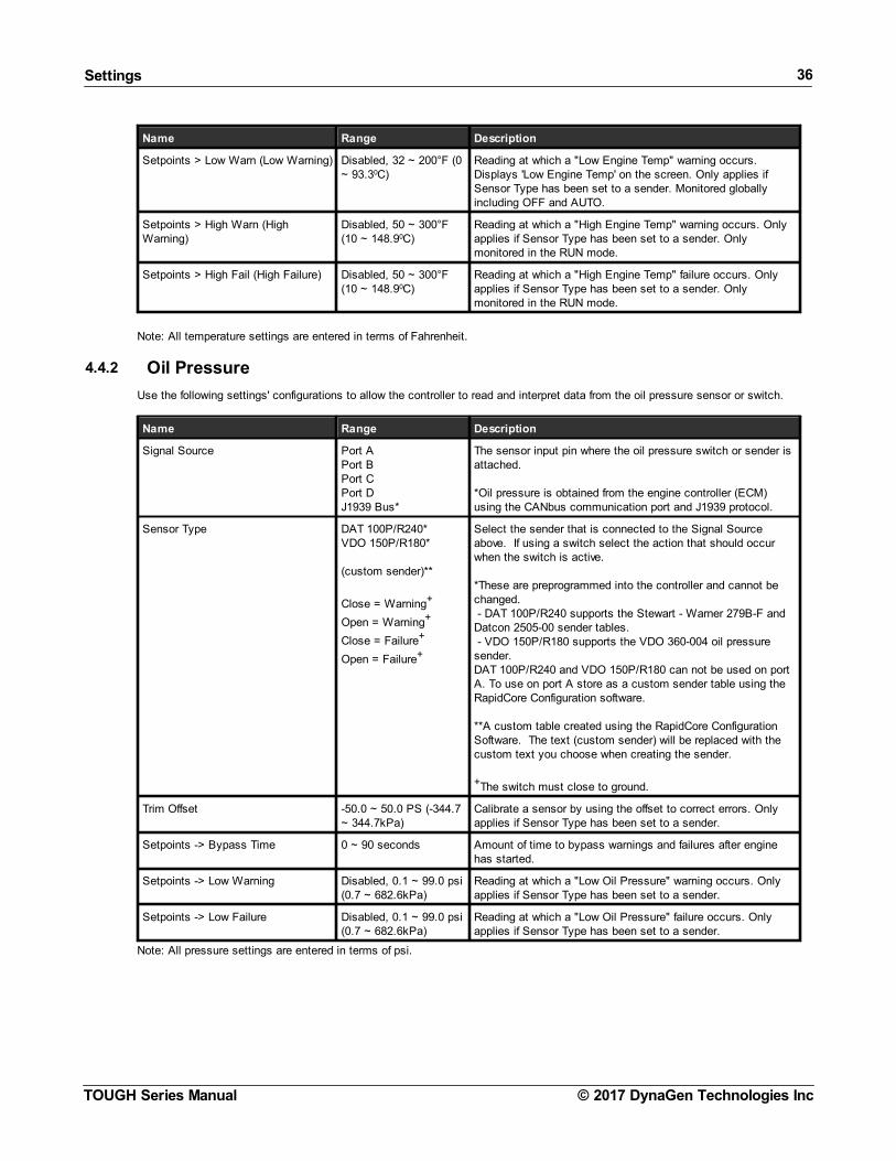
4.4.2 Oil Pressure
Use the following settings' configurations to allow the controller to read and interpret data from the oil pressure sensor or switch.
Name Range Description
Signal Source Port APort BPort CPort DJ1939 Bus*
The sensor input pin where the oil pressure switch or sender isattached.
*Oil pressure is obtained from the engine controller (ECM)using the CANbus communication port and J1939 protocol.
Sensor Type DAT 100P/R240*VDO 150P/R180*
(custom sender)**
Close = Warning+
Open = Warning+
Close = Failure+
Open = Failure+
Select the sender that is connected to the Signal Sourceabove. If using a switch select the action that should occurwhen the switch is active.
*These are preprogrammed into the controller and cannot bechanged. - DAT 100P/R240 supports the Stewart - Warner 279B-F andDatcon 2505-00 sender tables. - VDO 150P/R180 supports the VDO 360-004 oil pressuresender.DAT 100P/R240 and VDO 150P/R180 can not be used on portA. To use on port A store as a custom sender table using theRapidCore Configuration software.
**A custom table created using the RapidCore ConfigurationSoftware. The text (custom sender) will be replaced with thecustom text you choose when creating the sender.
+The switch must close to ground.
Trim Offset -50.0 ~ 50.0 PS (-344.7~ 344.7kPa)
Calibrate a sensor by using the offset to correct errors. Onlyapplies if Sensor Type has been set to a sender.
Setpoints -> Bypass Time 0 ~ 90 seconds Amount of time to bypass warnings and failures after enginehas started.
Setpoints -> Low Warning Disabled, 0.1 ~ 99.0 psi(0.7 ~ 682.6kPa)
Reading at which a "Low Oil Pressure" warning occurs. Onlyapplies if Sensor Type has been set to a sender.
Setpoints -> Low Failure Disabled, 0.1 ~ 99.0 psi(0.7 ~ 682.6kPa)
Reading at which a "Low Oil Pressure" failure occurs. Onlyapplies if Sensor Type has been set to a sender.
Note: All pressure settings are entered in terms of psi.

Settings 37
© 2017 DynaGen Technologies IncTOUGH Series Manual
4.4.3 Fuel Level
Use the following settings' configurations to allow the controller to read and interpret data from the fuel level sensor.
Name Range Description
Signal Source Port APort BPort CPort D
The sensor input pin where the fuel level switch or sender isattached.
Sensor Type DAT R/33-240*VDO R/0-180*
(custom sender)**
Close = Warning+
Open = Warning+
Close = Failure+
Open = Failure+
Select the sender that is connected to the Signal Sourceabove. If using a switch select the action that should occurwhen the switch is active.
*These are preprogrammed into the controller and cannot bechanged.- DAT R33-240 supports a Dacon fuel level sensor of the range33 Ohms to 180 Ohms- VDO R/0-180 supports a VDO fuel level sensor of the range 0Ohms to 180 OhmsDAT R33-240 and VDO R/0-180 can not be used on port A. Touse on port A store as a custom sender table using theRapidCore Configuration software.
**A custom table created using the RapidCore ConfigurationSoftware. The text (custom sender) will be replaced with thecustom text you choose when creating the sender.
+The switch must close to ground.
Trim Offset -50.0 ~ 50.0% Calibrate a sensor by using the offset to correct errors. Onlyapplies if Sensor Type has been set to a sender.
Setpoints -> Bypass Time 0 ~ 90 seconds Amount of time to bypass warnings and failures after enginehas started.
Setpoints > Low Warning Disabled, 1 ~ 90% Reading at which a "Low Fuel Level" warning occurs. Onlyapplies if Sensor Type has been set to a sender. Onlymonitored in the RUN mode.
Setpoints > Low Failure Disabled, 1 ~ 90% Reading at which a "Low Fuel Level" failure occurs. Onlyapplies if Sensor Type has been set to a sender. Onlymonitored in the RUN mode.
Setpoints > High Warning Disabled, 1 ~ 125% Reading at which a "High Fuel Level" warning occurs. Displays'High Fuel Level' on the screen. Only applies if Sensor Type hasbeen set to a sender. Monitored globally including OFF andAUTO.
4.4.4 Engine Speed
Use the following settings' configurations to allow the controller to read and interpret speed sensing data.
Name Range Description
Signal Source J1939 BusMag PickupGenset Voltage (default)
The source for the engine speed signal.
J1939 -- Engine speed is obtained over the engine CANcommunication bus .Genset Voltage -- The AC Voltage connector phase A is usedfor engine speed.Mag Pickup -- A magnetic pickup, alternator output, or thedistributer signal can be used to sense speed. Must use J6pins 7 and 8. If using a distributer a filter is often required.Contact DYNAGEN for more information on using a distributersignal.

Settings 38
© 2017 DynaGen Technologies IncTOUGH Series Manual
Name Range Description
Speed Settings > Rated RPM 500 ~ 4000 RPM in 1RPM increments
Speed at which the engine runs under normal operatingconditions. Warning and failure setpoints are calculated fromthis setting.
Speed Settings > Idle RPM 300 ~ 2000 RPM in 1RPM increments
Speed at which the engine runs when it is idling.
Speed Settings > Tooth Count 1 ~ 600 (only applies when Signal Source is set to Mag Pickup)Number of teeth on the flywheel.
If the number of teeth is unknown the following formula can beused. A multimeter must be used to measure the ACfrequency (Frequency-In-Hz below) from the magnetic pickup.The speed (Speed-In-Rpm below) must be known.
Tooth-Count = (Frequency-In-Hz * 60) / Speed-In-Rpm
Setpoints > Low Warn (UnderSpeedWarning)
20 ~ 99% Reading at which a warning occurs.
Setpoints > Low Fail (UnderSpeedFailure)
20 ~ 99% Reading at which a failure occurs.
Setpoints > High Warn (OverSpeedWarning)
101 ~ 150% Reading at which a warning occurs.
Setpoints > High Fail (OverSpeedFailure)
101 ~ 150% A over speed failure is triggered if the speed is above thisthreshold for 4 seconds.
RPM Control > Min Speed Submenu
Front Panel Speed Control SettingsSee Front Panel SpeedControl section for more information on these settings.
RPM Control > Max Speed
RPM Control > Speed Bias
RPM Control > Tsc1 RPM/s
RPM Display BlankAC HertzAux Sensor 1Aux Sensor 2
RPM Switch > Secondary(Secondary RPM / 50Hz)
500 ~ 4000 The Rated RPM when the Secondary RPM / 50Hz is selected.See RPM / Frequency Select section for more information.
RPM Switch > Primary (PrimaryRPM / 60Hz)
500 ~ 4000 The Rated RPM when the Primary RPM / 60Hz is selected.See RPM / Frequency Select section for more information.
NOTE: When using J1939 or Genset Voltage as a signal source, connections to the speed sensing terminals are notrequired.IMPORTANT: When using Genset Voltage as a signal source the voltage source must be connected to terminal A(J7-1). AC frequency is sensed on terminal A only.
NOTE: Speed is monitored at the start of cranking. If there is speed detected above the crank disconnect setting thencranking and idle is skipped.The speed is not monitored during delay-to-start or preheat as this provides some degree of protection againstspurious signals due to noise. The fuel input is turned on at the start of preheat and often powers external equipmentthat can cause noise.

Settings 39
© 2017 DynaGen Technologies IncTOUGH Series Manual
4.4.4.1 Front Panel Speed Control
The operator is able to adjust the speed of the engine by using the controller's front panel. This section describes the two methodsavailable for implementing speed control, the settings and parameters to be used, as well as the necessary instructions allowingthe operator to control the speed.
Speed Control Methods
Setting Description
Front Panel Speed Control using J1939TSC1
The controller can instruct the ECM of an electronic engine to adjust its speed bybroadcasting the TSC1 command.
Refer to the J1939 Manual for more information.
Front Panel Speed Control using SwitchedOutputs
The controller can instruct the ECM of an electronic engine to adjust its speed byusing switched outputs on the controller set to RPM Increment and RPMDecrement to interface with digital inputs on the ECM. When the speed ischanged, the corresponding switched output will be on for 1 second each timeincrement or decrement is pressed.
See the rest of this section for more information.
Aux 4 Speed Control The Auxiliary sensor 4 is used to determine the setpoint speed. The speed isadjusted with the TSC1 J1939 command.
Refer to the J1939 Manual for more information.
WARNING: Switched outputs have a floating voltage of approximately 8V when off. If using the outputs for digital logic,it will be necessary to put a pull-down resistor (1kOhm, 1 Watt) from the output to ground to ensure a low logic levelwhen output is off.
Front panel speed control using the Switched Outputs
Settings
Name Parent Menu Range Description
SpeedControlEnable
Configuration Softwareonly. Engine Speed menu.
Enable ~Disable
Enables or disables front panel speed control.
RPM Display Sensors > Engine Speed Nothing / BlankAC FrequencyAuxiliarySensor 1AuxiliarySensor 2
Parameter to display when adjusting speed from front panel. Thisis used to provide operator feedback in the case that the engineRPM affects another parameter such as AC Frequency or anAuxiliary Sensor (Example: Flow rate of pump).
Limit Method Configuration Softwareonly. Engine Speed menu.
Speed BiasMin RPM / MaxRPM
The method in which the minimum and maximum speeds theoperator is allowed to adjust is determined.
Speed Bias Sensors > Engine Speed >RPM Control
0 ~ 600 RPM in1 RPMincrements
The minimum or maximum RPM that the engine speed can beadjusted around the Rated RPM. Example: Rated RPM is 1800and Speed Bias is 150. The minimum RPM will be 1650 andmaximum RPM will be 1950. Only valid when the correct limitmethod is chosen.
Min Speed 500 ~ 4000RPM in 1 RPMincrements
The minimum RPM that can be set using speed control. Only validwhen the correct Limit Method is chosen.
Max Speed 500 ~ 4000RPM in 1 RPMincrements
The maximum RPM that can be set using speed control. Only validwhen the correct Limit Method is chosen.
Tsc1 RPM/s Sensors > Engine Speed >RPM Control
Disable, 10 ~300 RPM/s in10 RPM/sincrements
Ignore this setting. Refer to the J1939 reference manual forinformation on this setting.

Settings 40
© 2017 DynaGen Technologies IncTOUGH Series Manual
Speed Control InstructionsWhen the controller is running and there are other functions occurring, the controller will scroll through its display parameters asusual. When the speed control page is displayed, it will show the Engine Speed as well as the following instructions: Hold AUTO +Up/Down to Adjust RPM.
Speed Control Parameter Page Speed Control Adjust Page
Pressing and holding the AUTO button will display the screen to the right. If a 'Display Adjust Parameter' is set, it will also bedisplayed underneath the Engine Speed. While still holding the AUTO key, press the up or down arrows to adjust the RPM. TheEngine Speed display should update as the engine physically changes its speed to accommodate the speed request.
NOTE: When using switched outputs for speed control, the Set RPM will display '---' instead of the set speed.
4.4.5 Battery Level
Use the following settings' configurations to allow the controller to read and interpret the battery voltage level.
Name Range Description
Battery Recharge Enable ~ Disable Enables or disables the ability to have the engine start on lowbattery voltage in order to charge it.
Recharge Setup -> Level 6.0 - 30.0V Voltage level at which the controller starts the engine torecharge the battery.
Recharge Setup -> Pre-Alarm 1 ~ 30 minutes Amount of time to display a warning before starting the engine.
Recharge Setup -> Duration 10 ~ 900 minutes Amount of time to run the engine.
Setpoints -> Low Warning 6.0 ~ 24.0V Reading at which a warning occurs.
Setpoints -> Low Failure 6.0 ~ 24.0V Reading at which a failure occurs.
Setpoints -> High Warning 12.0 ~ 32.0V Reading at which a warning occurs.
Setpoints -> High Failure 12.0 ~ 32.0V Reading at which a failure occurs.
Crank Low Batt 6.0 ~ 24.0V Screen displays a 'Low Voltage During Cranking' warning ifvoltage dips below this level during cranking.
NOTE: When the engine is running, the battery voltage will equal the alternator charging voltage. The actual open-circuit battery voltage may be lower than displayed.
Battery Recharge Sequence

Settings 41
© 2017 DynaGen Technologies IncTOUGH Series Manual

Settings 42
© 2017 DynaGen Technologies IncTOUGH Series Manual
4.4.6 Auxiliary Sensors
The Auxiliary sensors are used for supporting custom sensors and triggering actions based on the sensor values.
You must use the RapidCore Configuration Software to program a custom sender table to the controller for the auxiliarysensor(s) that will be used. Otherwise "Undefined Sensor" will appear menu in the front panel menu system. Once a sender tableis programmed to the controller all the other settings can be adjusted from the front panel of the controller.
(Sensors > Aux Sensor 1/2/3/4 menus)
Name Range Description
Signal Source DisablePort APort BPort CPort D
The source where to get the signal for the aux. sensor.
Any port can be used even if it is used by another sensor or aux.sensor. If the port is in use by other sensor this is known as overloading the port.
Custom Sender (ConfigurationSoftware only)
---
The sender resistance / value curve must be programmed from theRapidCore Configuration Software even if the port is beingoverloaded. This tells the controller how to interpret the signal fromthe port. No front panel configuration is allowed until the sendercurve is programmed to the controller.
Display EnableDisable
Determines if the sensor's value is displayed on the screen when theengine is running.
Active Mode DisableGlobalOFF Mode (Not in Auto)Auto ModeRunningCrankingAfter CrankingCooldown
Determines under which operating conditions the Auxiliary Sensor ismonitored. Multiple selections are allowed. Does not apply to "Starton Low" or "Start on High"; for those selections the active mode isalways AUTO.
Refer to the examples in the following pages for information onspecific mode functions.
Disable - Input cannot be triggered.Global - Input can be triggered at any time.OFF Mode - Input can be triggered while in the OFF mode.Auto Mode - Input can be triggered while in the AUTO mode.Running - Input can be triggered after a start command is receiveduntil shut down (cooldown not included).Cranking - Input can be triggered during cranking.After Cranking - Input can be triggered after engine has started untilshut down.Cooldown - Input can be triggered while cooldown timer is active.
Func. Select Fault MonitorOutput on LowOutput on HighStart on LowStart on High
Determines how the controller responds to the readings of theauxiliary sensor.
"x on Low" will turn on the output or start the controller if the sensorinput falls below the Start Level."x on High" will turn on the output or start the controller if the sensorinput rises above the Start Level.
Trim Offset -50.0 ~ 50.0 units. Theunits depends on the unittype of the programmedsender table -- 0F, psi, %,V, A.
Calibrate a sensor by using the offset to correct errors.
Mode Settings > Bypass Time 0 ~ 90, 1 secondincrements
The amount of time to ignore the sensor input after the desired activemode is first entered. Once triggered the bypass time does notapply again until the device resets (for example transitioning fromRUN to the OFF or AUTO state) or on power-up.
Mode Settings > Run Time Disable1 ~ 60001, 1 minuteincrements
(Only applies if Func. Select is not set to Fault Monitor) The amountof time to turn on the auxiliary switched output or run the controllerbefore turning off the output or shutting down the controller.

Settings 43
© 2017 DynaGen Technologies IncTOUGH Series Manual
Name Range Description
If the Run Time is disabled then the start/output is held until theStop Level is reached (if enabled) or until the controller is reset orpowered down or, in the case of Start on Low / Start on High, untilthe user presses the OFF button.
Note that the run time is not exact. Up to 10 seconds may beadded to the beginning of the run time counter and up to 4 secondsto the end. The run time begins when a start request is received socrank time, preheat time, etc is included in the Run Time.
Mode Settings > Start Level
DisableTemperature: 32 ~ 999, 1 0F incrementsPressure: 1 ~ 6000, 1 psiincrementsLevel: 1 ~ 99, 1 %incrementsVoltage: 0.1 ~99.9, 0.1 VincrementsCurrent: 1 ~ 999, 1 Aincrements
(Only applies if Func. Select is not set to Fault Monitor) The level atwhich the auxiliary switched output turns on or the engine starts.
If this is set to Disable, the Aux sensor action defined in Func.Select is disabled. The Auxiliary sensor becomes display only(unless Func. Select is set to Fault Monitor).
Mode Settings > Stop Level (Only applies if "Func. Select" is not set to Fault Monitor) The levelat which the auxiliary switched input turns off or the engine isstopped.
If Stop Level is disabled the start/output condition is maintained untilthe Run Time expires (if enabled) or until the controller is reset orpowered down or in the case of a start until the user presses theOFF button.
Setpoints > Low Warning (Only applies if "Func. Select" is set to Fault Monitor) Reading atwhich a warning occurs.
Setpoints > Low Failure (Only applies if "Func. Select" is set to Fault Monitor) Reading atwhich a failure occurs.
Setpoints > High Warning (Only applies if "Func. Select" is set to Fault Monitor.) Reading atwhich a warning occurs.
Setpoints > High Failure (Only applies if "Func. Select" is set to Fault Monitor.) Reading atwhich a failure occurs.
1 1 ~ 600 minutes for firmware versions below 1.78.
If using Output on Low or Output on High one of the switched outputs events must be set to one of the following corresponding tothe Aux. Sensor being configured per the table below.
(Switched I/O > Switched Out A/B/C/D/EF > Events menus)
Name Description
Aux Sensor 1 Used by the Aux. Sensor 1 Output On Low or Output on Highfeature.
Aux Sensor 2 Used by the Aux. Sensor 2 Output On Low or Output on Highfeature.
Aux Sensor 3 Used by the Aux. Sensor 3 Output On Low or Output on Highfeature.
Aux Sensor 4 Used by the Aux. Sensor 4 Output On Low or Output on Highfeature.
The display resolution of the auxiliary sensors that are displayed on the screen are different than the resolution used for thepurpose of the comparisons that determine if the start level, stop level, low warning, etc are in effect. The resolutions are givenbelow.
Sensor Unit Type Comparison Resolution
Temperature 1 0F
Pressure 1 psi
Level 1 %

Settings 44
© 2017 DynaGen Technologies IncTOUGH Series Manual
Sensor Unit Type Comparison Resolution
Voltage 0.1 V
Current 1 A
Example: if the auxiliary sensor 1 (aux 1) is using a temperature sender curve, set to Output on Low, and the Start Level is set to130 0F then the Output will not turn on until the temperature drops to 129 0F since the resolution for comparisons is 1 0F.
The below tables gives all the possible actions that the auxiliary sensors can perform.
Behavior Func.Select
Start Level Run Time Stop Level
A -Indefinitel
y
Start controller when the sensordrops below a certain value. Runindefinitely.1
Start on Low Set to value that thesensor needs to dropbelow to start.
Disable Disable
Turn on an output when the sensordrops below a certain value. Keepon the output indefinitely.2
Output onLow
Set to value that thesensor needs to dropbelow to turn on theoutput.
Disable Disable
Start controller when the sensorrises above a certain value. Runindefinitely.1
Start onHigh
Set to value that thesensor needs to riseabove to start.
Disable Disable
Turn on an output when the sensorrises above a certain value. Keepthe output on indefinitely.2
Output onHigh
Set to value that thesensor needs to riseabove to turn on theoutput.
Disable Disable
B - FixedDuration
Start controller when the sensordrops below a certain value. Runfor a fixed period of time and thenstop controller.
Start on Low Set to value that thesensor needs to dropbelow to start.
Set to the desired runduration.
Disable
Turn on an output when the sensordrops below a certain value. Runfor a fixed period of time and thenturn off the output.
Output onLow
Set to value that thesensor needs to dropbelow to turn on theoutput.
Set to the desiredduration to keep theoutput on.
Disable
Start controller when the sensorrises above a certain value. Run fora fixed period of time and thenstop controller.
Start onHigh
Set to value that thesensor needs to riseabove to start.
Set to the desired runduration.
Disable
Turn on an output when the sensorrises above a certain value. Run fora fixed period of time and then turnoff the output.
Output onHigh
Set to value that thesensor needs to riseabove to turn on theoutput.
Set to the desiredduration to keep theoutput on.
Disable
C - StartLevel /
Stop Level
Start controller when the sensordrops below a certain value. Stopcontroller when the sensor risesabove a certain value.
Start on Low Set to value that thesensor needs to dropbelow to start.
Disable Set to the valuethe sensor needsto rise above tostop the controller.
Turn on an output when the sensordrops below a certain value. Turnoff output when the sensor risesabove a certain value.
Output onLow
Set to value that thesensor needs to dropbelow to turn on theoutput.
Disable Set to the valuethe sensor needsto rise above toturn off the output.
Start controller when the sensorrises above a certain value. Stopcontroller when the sensor dropsbelow a certain value.
Start onHigh
Set to value that thesensor needs to riseabove to start.
Disable Set to the valuethe sensor needsto drop below tostop the controller.
Turn on an output when the sensorrises above a certain value. Turn offoutput when the sensor dropsbelow a certain value.
Output onHigh
Set to value that thesensor needs to riseabove to turn on theoutput.
Disable Set to the valuethe sensor needsto drop below toturn off the output.

Settings 45
© 2017 DynaGen Technologies IncTOUGH Series Manual
D - StartLevel /
Stop Levelwith
timeout
Start controller when the sensordrops below a certain value. Stopcontroller when the sensor risesabove a certain value. Stop thecontroller after a fixed time if thestop level is not reached.
Start on Low Set to value that thesensor needs to dropbelow to start.
Set to the desiredmaximum run duration(i.e. this is thetimeout).
Set to the valuethe sensor needsto rise above tostop the controller.
Turn on an output when the sensordrops below a certain value. Turnoff output when the sensor risesabove a certain value. Turn off theoutput after a fixed time if the stoplevel is not reached.
Output onLow
Set to value that thesensor needs to dropbelow to turn on theoutput.
Set to the desiredmaximum duration tokeep the output on(i.e. this is thetimeout).
Set to the valuethe sensor needsto rise above toturn off the output.
Start controller when the sensorrises above a certain value. Stopcontroller when the sensor dropsbelow a certain value. Stop thecontroller after a fixed time if thestop level is not reached.
Start onHigh
Set to value that thesensor needs to riseabove to start.
Set to the desiredmaximum run duration(i.e. this is thetimeout).
Set to the valuethe sensor needsto drop below tostop the controller.
Turn on an output when the sensorrises above a certain value. Turn offoutput when the sensor dropsbelow a certain value. Turn off theoutput after a fixed time if the stoplevel is not reached.
Output onHigh
Set to value that thesensor needs to riseabove to turn on theoutput.
Set to the desiredmaximum duration tokeep the output on(i.e. this is thetimeout).
Set to the valuethe sensor needsto drop below toturn off the output.
E -Warnings/Failures
Trigger warnings and/or failures onthe sensor.
FaultMonitor
N/A N/A N/A
F -Display
only
Do not perform any actions on thesensor value. Just display thevalue to the user.
FaultMonitor(Disable allwarningsand failures)
N/A N/A N/A

Settings 46
© 2017 DynaGen Technologies IncTOUGH Series Manual
1 The user must manually stop the controller by pressing the run button.2 The controller must be powered down or a reset initiated by changing a setting in the menu and existing a menu or going from theRUN mode to the AUTO or OFF mode.
4.4.6.1 Fault Monitor Example
In this example, a sensor is monitoring the temperature of an engine block. If the temperature rises above 275°F, a warningmessage is displayed. If the temperature rises above 350°F, the engine shuts down and a failure message is displayed.
Relevant Settings
Setting Value
Signal Source Same as Engine Temperature
Display Disable (If enabled, controller will display Engine Temperature twice)
Sensor Type Same as Engine Temperature
Sensor Table Name Engine Temp.
Active Range Running
Mode Select Fault Monitor
Setpoints -> Low Warning Disabled
Setpoints -> Low Failure Disabled
Setpoints -> High Warning 275°F
Setpoints -> High Failure 350°F
The chart above shows the connection between engine temperature and time. At approximately 13 minutes run time, thetemperature rises above the 275°F warning threshold, activating the warning display. The engine will continue to run because it hasnot reached the 350°F failure threshold. At 20 minutes run time, the temperatures falls below the warning threshold and the warningdisappears.

Settings 47
© 2017 DynaGen Technologies IncTOUGH Series Manual
4.4.6.2 Start on Low Example
In this example, a sensor is monitoring the voltage of an external battery bank. If the voltage falls below 10.5V, the engine will startand run for 40 minutes to charge the battery.
Relevant Settings
Setting Value
Signal Source Sensor Port X
Display Enable
Sensor Type Custom
Sensor Table Name Battery Bank
Active Range N/A (These ranges are fixed for Start on Low / High)
Mode Select Start on Low
Mode Settings -> Active Time 40 minutes
Mode Settings -> Start Level 10.5V
Mode Settings -> Stop Level1 Disabled
1 Stop Level needs to be disabled when the engine is running because the battery voltage will equal the alternator charging voltage. Having this disabled will force the engine to run for the entire duration of the active time.
The chart above shows the connection between a battery bank and time. At approximately 80 minutes time, the voltage falls belowthe 10.5V start threshold causing the engine to start. The engine runs for the 40 minutes active time regardless of the voltagereading and then shuts down.

Settings 48
© 2017 DynaGen Technologies IncTOUGH Series Manual
4.4.6.3 Output on High Example
In this example, a sensor is monitoring the temperature of an engine. If the temperature rises above 325°F, a fan will turn on to coolthe engine. Once the temperature drops to below 200°F the fan will turn off.
Relevant Settings (Auxiliary Sensor)
Setting Value
Signal Source Same as Engine Temperature
Display Disable (If enabled, controller will display Engine Temperature twice)
Sensor Type Same as Engine Temperature
Sender Table Name Engine Temp.
Active Range Global
Mode Select Output on High
Mode Settings -> Active Time1 Disabled
Mode Settings -> Start Level 325°F
Mode Settings -> Stop Level 200°F
1 Active time is disabled because the fan needs to stay on indefinitely or until 200°F is reached.
Relevant Settings (Switched Outputs)
Setting Value
Switched Output X Auxiliary Sensor X (Choose based on which Auxiliary Sensor is being used)
The chart above shows the connection between engine temperature and time. At approximately 10 minutes run time, thetemperature rises above the 325°F start threshold and the fan turns on. The fan continues to run as the temperature declines.When the temperature falls below the 200°F stop threshold, the fan turns off.

Settings 49
© 2017 DynaGen Technologies IncTOUGH Series Manual
4.4.6.4 Sensor as a Switch
Reserved for future use.
4.4.7 Custom Sensor Tables
Custom Sensor Tables are created using the RapidCore Configuration Software when using a sensor that is not supported byDYNAGEN. The configurator has the ability to create these custom tables, allowing the controller to properly read the sensor data.
NOTE: Custom sender tables can only be created when using the configuration software.
Parameter Description
Name The label that will be displayed in the controller (Engine Temp, Oil Pressure, etc.)
Input TypeChoose resistance, voltage or current based on the sensor type. Use the TerminalDescriptions section to determine if your sensor is compatible with a sensor port.
Unit TypeChoose temperature, pressure, voltage, current or percentage based on the sensor. Thisdefines what unit of measurement will be displayed on the front panel (0F, psi, V, A, %).
The following example outlines the steps for creating a custom sensor table:
1. Navigate to the sensor input that will be using your custom sensor table.2. Select a Name, Input Type and Unit Type for the controller (Definitions in table above).3. Click the check box next to 'Build Table' (Image Step 1).4. From the 'Sender' drop down menu, select 'Custom' (Image Step 2).5. Click the 'Edit' button next to the drop down menu (Image Step 3).6. Enter the sensor values. Once entered, click Apply then OK.

Settings 50
© 2017 DynaGen Technologies IncTOUGH Series Manual
4.5 TimersThe controller has an internal clock which is used not only to keep time, but to ensure programed events happen at the correcttimes. The following sections are used to configure settings associated with timing functions.
NOTE: The controller has an on-board backup battery to keep time even when main power is not supplied to the unit.This battery has an unpowered (no main power) lifetime of approximately five years.
4.5.1 Engine Logic
The following settings determine how the controller starts and stops the engine. It gives the user the functionality to add delays andtimers to the sequences. Most of the settings have a switched output associated with them that must be set in the SwitchedOutputs settings.
NOTE: Setting a timer's value to 0 seconds will disable the timer. Example: If Delay to Start is set to 0 seconds, thecontroller will not perform a Delay to Start when starting the engine.
Timers > Engine Logic:
Name Range Description
Delay to Start 0 ~ 90 seconds Amount of time to delay the starting of the engine afterreceiving a command to start.
DTS Manual Run (Delay to Start onManual Run)
Enable ~ Disable Determines if the the Delay to Start timer is used when thefront panel RUN button is used to start the engine.
Preheat Mode Preheat TimerSwitched InputJ1939
Determines the method used to control enabling the glowplugoutput. See the Preheat Mode section for more information.
Preheat Time 0 ~ 1200 seconds0 ~ 90 in firmwareversions below 1.33.
Amount of time the Glowplug output is active before crankingthe engine. Used on diesel engines to warm the engine beforecranking.
Crank Time 3 ~ 30 seconds Amount of time the Crank output is active before going to crankrest. This timer immediately expires upon successful cranking.
Midheat Time 0 ~ 90 seconds Keeps Glowplug output turned on while cranking but not duringcrank rest. Output will turn off upon crank failure, cranksuccess or midheat time expiration.
Crank Rest Time 1 ~ 90 seconds Amount of time to delay between each attempt to start theengine.
Crank Attempts 1 ~ 20 Number of attempts to start the engine before going to anovercrank failure.
Fuel In Rest (Fuel Crank Rest) Fuel ONFuel OFF
Determines if the fuel output stays on during the crank resttime.
RPM Disconnect 100 ~ 2000 rpm Speed at which controller determines the engine has startedsuccessfully and turns off the Crank output.
Postheat Time 0 ~ 90 seconds Amount of time the Glowplug output remains on after cranksuccess and the engine is running.
False Restart (Restart on FalseStart)
Enable false start (engine stall) detection. Refer to the False Restart section.False Check (False Restart DetectTime)
Warmup Time 0 ~ 600 s in 5 sincrements
After successful cranking, engine delays this amount of timebefore turning on the Warmup output. This allows the engine towarm up before applying any load to it. The output will turn offwhen the controller enters the Cooldown Delay.
OFF Button Function CooldownShutdownForce Cooldown
The function the OFF button on the front panel performs whileengine is running. See the OFF Button Function section formore information.

Settings 51
© 2017 DynaGen Technologies IncTOUGH Series Manual
Name Range Description
Cooldown Time 0 ~ 600 s in 5 sincrements
Amount of time to cool down the engine after a stop commandhas been received. During this time the Warmup output turnsoff and the Cooldown output turns on. If another start commandis received during cool down, the controller will return to runningmode.
ETS On Duration (Energize to Stop) 0 ~ 30 seconds Amount of time the Energize to Stop output is on after theengine has shut down. If controller still detects speed (RPM)after this time expires, it goes to a 'Failed to Stop' failure. Timemust be greater than 0 seconds for the Energize to Stopfunction to work.
Warm-up Idle
Idle during warm-up option. See the Idle section for more information.Idle Settings
Cooldown Idle
Auto Idle Link
4.5.1.1 Preheat Mode
The controller has the ability to control the length of the preheat time through 3 different methods. The table below describes eachmethod:
Preheat Mode Setting (Timers > Engine Logic menu)
Mode Description
Preheat Timer This mode uses the Preheat Time setting in the Engine Logic menu.
Switched Input This mode uses a switched input set to 'ECM Preheat' to determine when to exitpreheat.
The preheat time (in Engine Logic) must be set to a minimum of 5 seconds for thisinput to work. If the switched input is or becomes active when the preheat timer iscounting down the controller displays 'ECM Preheating' on the screen after thepreheat counter has finished its countdown. Cranking begins when the 'ECMPreheat' switched input is no longer active.
J1939 This mode uses commands sent from the ECM over J1939 to decide when to exitpreheat.
NOTE: During preheat the Glowplug switched output is on (it needs to be set to a switched output -- see SwitchedOutputs).
4.5.1.2 False Restart
The false restart feature is used to monitor and recover from unsuccessful crank attempts where the speed did go above the crankdisconnect and the controller is in the RUN mode. For example the engine might have stalled shortly after cranking.
False Restart settings (under Timers > Engine Logic menu)
Name Range Description
False Restart (Restart on FalseStart)
EnableDisable
Determines if the controller will monitor for false starts andattempt a restart. Controller will only attempt restarting theengine as many times as determined by Crank Attempts.
False Check (False Restart DetectTime)
5 ~ 30 in 1 secondintervals
Amount of time after successful cranking to monitor for a falserestart. A false restart is defined as the speed dropping below250 RPM for 2 seconds. If this time expires and the enginesstalls out, the controller will not attempt a restart.
This time starts from crank success.
Tip: It takes up to 2 seconds for the false restart to be triggered. In addition it takes time for the engine speed to drop below250RPM. These should be measured and added to the desired False Check setting.

Settings 52
© 2017 DynaGen Technologies IncTOUGH Series Manual
For example when the speed is disconnected it takes approximately 2.5 s for the speed sensing to record 0 RPM when the speedsensing is set to a magnetic input at a speed of 3200Hz/1800RPM. This is 4.5 s including the 2 s for the false restart delay. So ifthe desired monitoring period is 10 s, the False Check setting should be set to 15 s.
4.5.1.3 OFF Button Function
The OFF button on the front panel of the controller can be configured to function in 3 different ways while the engine is running. Thetable below describes each of these functions:
Function Description
Cooldown This function causes the controller to go into cooldown. Pressing the OFF buttonagain will cause the engine to shut down.
Shutdown This function bypasses Cooldown and causes the engine to shut down.
Force Cooldown This function causes the controller to activate the cooldown process. Pressing theOFF button will have no affect as the controller is forcing the engine to perform a fullcool down.
WARNING: If the controller receives a command to start from the remote start or front panel run button while inCooldown, it will leave the Cooldown mode and go back to Running mode.

Settings 53
© 2017 DynaGen Technologies IncTOUGH Series Manual
4.5.1.4 Idle
Controller ignores under speed, voltage and frequency warnings and failures when active. If using J1939, the controller willbroadcast TSC1 as the Idle Speed parameter found in the Engine Speed section.
This section explains the general idle functionality.
There are three ways to use idle:1. Idle Warmup -- Automatically enter the idle mode during warmup for a period of time before going to rated speed. See Warmup
Idle.2. Cool down Idle -- Idle automatically during cool down. See below.3. Idle Switched Input -- Idle whenever this switched input is active. See the Idle Mode function under Switched Inputs.
Name Parent Menu Range Description
Cooldown Idle Timers > Engine Logic DisableEnable
Idle during cooldown.
Auto Idle Link Timers > Engine Logic Disable,Breaker Trip
If set to breaker trip, the breaker trip will beactivated whenever the controller is in the Idlemode. The breaker trip will be turned off whenIdle mode is exited if it was not in the latchedstate.
If the user delaches the breaker trip output whileauto idle is active the breaker trip will turn off forone section and then turn back on.
4.5.1.4.1 Warmup Idle
This section explains the Warmup Idle functionality.
The warmup idle is used to run the engine at a reduced speed at engine start.
Name Parent Menu Range Description
Warm-up Idle Timers > Engine Logic DisableWarm-up TimerOil Temp.Engine Temp.
If enabled the engine is placed in Idle modeduring the warm-up period.
Warm-up Timer -- The engine idles during theduration of the warm-up timer countdown.Oil Temp. -- The oil temperature over J1939 isused to determine the extent of the warm-up /Idle period. Engine Temp. -- Same as Oil Temp. but theengine temperature is used. The enginetemperature can come locally or from J1939.
The oil temp and engine temp selections usethe Debounce, Low Point, and High Pointsettings below.
Debounce Timers > Engine Logic >Idle Settings
1 to 10s, 1sincrements
(Warm-up Idle) If the temperature remainsbetween the "Low Point" and "High Point"settings for this time exit the warm-up / idle.
Low Point Timers > Engine Logic >Idle Settings
1 to 1800F, 10Fincrements
(Warm-up Idle) Continue to idle when thetemperature is below this setting. Ignore theDebouce.
High Point Timers > Engine Logic >Idle Settings
1 to 1800F, 10Fincrements
(Warm-up Idle) Always exit idle when thetemperature is above this setting.
Cooldown Idle Timers > Engine Logic DisableEnable
Idle during cooldown.

Settings 54
© 2017 DynaGen Technologies IncTOUGH Series Manual
Name Parent Menu Range Description
Auto Idle Link Timers > Engine Logic Disable,Breaker Trip
If set to breaker trip, the breaker trip will beactivated whenever the controller is in the Idlemode. The breaker trip will be turned off whenIdle mode is exited if it was not in the latchedstate.
If the user delaches the breaker trip output whileauto idle is active the breaker trip will turn off forone section and then turn back on.
4.5.1.4.2 Idle Inhibit
Use this feature to prevent start up when the Idle mode switch is active.
Settings (Other Config > Idle Inhibit, in the Configuration Software these are under the switched inputs when the idle input isenabled.)
Name Range Description
Remote Start (Start /Stop Switched InputInhibit)
EnableDisable
Prevent the remote start switch input from starting the engine when the idleswitch is active.
Aux Start (Aux 1,2,3,4Sensor Autostart Inhibit)
EnableDisable
Prevent Auxiliary 1, 2, 3, and 4 sensors autostart feature from starting theengine when the idle switch is active.
If the engine is in the IDLE mode because of the Warmup Idle feature, the remote start (start/stop) and auxiliary sensors autostartcan still start the engine.
This prevents starting when the Idle switch is active in the AUTO mode. This will also shutdown the engine if the idle switched inputis activated when the controller is in the delay-to-start, preheat, cranking, and crank reset states. The main purpose is to prevent aremote start if the idle switch was accidentally left on.
4.5.2 Schedulers
Enter topic text here.
4.5.2.1 Exerciser
The Exerciser function is used to start and run the engine periodically. The following settings configure the Exerciser function.
Exerciser Settings (in Timers menu)
Name Range Description
Enable Enable ~ Disable Enables the exerciser feature.
Delays -> Pre-Alarm 1 ~ 20 minutes Amount of time to display a warning before starting the engine.
Delays -> Run Time 10 ~ 1500 minutes Amount of time to run the engine.
Schedule -> Start Date 1 ~ 31 The day of the month and the time for the first exerciser run. This setting is only used to set the first exerciser run. Allsubsequent exerciser runs use the Repeat Days setting todetermine when they should run.
If the date and hour selected is already in the past for thecurrent month then the exerciser will be started on the nextmonth with that date and hour. Also if the date is not yet in thepast but the current month does not have that date (e.g.February 21 and a date of 31 is selected) the exerciser will runon the next month to have that date (e.g. 31rst of March) at thehour specified.
Schedule -> Start Hour 0 ~ 23

Settings 55
© 2017 DynaGen Technologies IncTOUGH Series Manual
Name Range Description
Schedule -> Repeat Days 1 ~ 28 days Number of days between each exerciser cycle. This setting isapplied to all subsequent exerciser starts after the first start.
Exerciser Sequence
If the controller is in the OFF mode, if the emergency stop is activated, or if the start inhibit is active then the exerciser will not run. The event, "Bypass Exerciser", will be logged in the event log and the exerciser will run again at the next scheduled time asdetermined by the "Repeat Days" setting.

Settings 56
© 2017 DynaGen Technologies IncTOUGH Series Manual
4.5.2.2 Weekly Scheduler
The weekly scheduler allows up to 16 unique weekly exercise times to be created.
Timers > Week Scheduler:
Name Range Description
Weekday Sunday ~ Saturday The day of the week the exercise will take place on.
Start time 24 hour clock in 1minute increments
When the exercise should start on a give day. At the selectedtime a one minute prealarm is displayed on the LCD screen. The controller starts after this one minute period.
Run time 10 ~ 1440 min in 1 minincrements
The duration of the exercise run period. Up to one day.
When entering the Week Scheduler menu there will be 16 sub menu items each corresponding to one of the 16 weekly exercisetimes. If disabled the entry will have dashed lines: "--- --:-- -----". If enabled the day of week, start time, and duration will bedisplayed for the menu. Press enter will enter the sub menu for that exerciser time.
It is recommended to use the RapidCore Configuration Software to enter the times as this provides a much more convenientinterface especially if daily exercise times are wanted.
4.5.2.3 Long Time Run
The Long Time Run counter can be used to shutdown the controller after a very long period of time. This is useful for remoteprimary power applications where the user wants to divide run time between two generators. When the countdown expires thecontroller will shutdown. Long Time Run is only active if the generator was started manually (i.e. by pressing the front Run button).
Timers > Long Time Run:
Name Range Description
Start Trigger Disable (Default)Manual Start
Set to "Manual Start" to enable the Long Time Run feature.
Run Duration 1 ~ 5000 hours in 1 hourincrement (Default =1000 hours)
The amount of time to run before shutting down.
4.5.3 Maintenance
The controller has the ability to count down the time between scheduled maintenance events. Once maintenance is required, thecontroller will alert the operator via the LCD screen and a switched output (if enabled) wired to a lamp / horn / buzzer. The followingsettings are used to configure the maintenance timer.
(Timers > Maintenance)
Name Range Description
Reset Counter Enable ~ Disable Once the maintenance count interval expires, use this settingto reset the time and turn off the switched output (if enabled).
Enable Counter Enable ~ Disable Enables or disables the maintenance function.
Count Interval 10 ~ 9990 hours Determines the number of hours between requiredmaintenance. A switched output can be configured to turn ononce the count interval expires.
To determine the amount of time until the next scheduled maintenance, follow these menu steps:
Main Menu -> Device Info. -> Maintenance
Maintenance counter is disabled if '----' is displayed. A negative number indicates the amount of time since maintenance timerexpired.

Settings 57
© 2017 DynaGen Technologies IncTOUGH Series Manual
NOTE: The maintenance timer displays "Service Required" when this time expires. This message is only displayed the next timethe controller enters the RUN mode. If the timer expires when the controller is in the RUN mode the message is not displayed.
4.6 AC MonitorThe controller has the ability to monitor AC voltage and current from a generator. The following sections are used to configuresettings associated with AC monitoring.
4.6.1 Generator Voltage
The following settings are used to configure the controller's response to voltage measurements.
(AC Monitor > Genset Voltage menu)
Name Range Description
Voltage Source Disable2-Wire Single3-Wire Single3-Wire 3-Phase4-Wire 3-Phase4-Wire DeltaAuto Selection
The wiring configuration of the generator. Disable will disableAC voltage and AC frequency sensing and display.
2-Wire Single: One 120VAC L-N. Use phase A.3-Wire Single: 120/240VAC systems. Use phases A and B.3-Wire 3-Phase: Three phase delta without a ground.4-Wire 3-Phase: Three phase Wye system. Center tapedground.4-Wire Delta: Delta with a ground. The high leg is phase B. Forexample if A-N and C-N read 120VAC then B-N will read208VAC.
Selecting Auto Selection will use the Voltage Select switchedinputs to determine the wiring configuration.
This setting also enables the AC Frequency monitoring anddisplay.
Scaling Factor 0.500 ~ 2.500 The gain to apply to the AC voltage that is read at thecontroller. See below for more information.
Nominal Volts 50 ~ 800 VAC* Generator voltage output when operating under normal runningconditions.
Auto Nominal > 1Ph 3-Wire (1-Phase3-Wire)
50 ~ 800 VAC* Nominal Volts when using the Voltage Select inputs.
Auto Nominal > 3-Phase (1) 50 ~ 800 VAC*
Auto Nominal > 3-Phase (2) 50 ~ 800 VAC*
Auto Nominal > 3-Phase (3) 50 ~ 800 VAC*
Auto Scaling > 1Ph 3-Wire (1-Phase3-Wire)
0.500 ~ 2.500 Scaling Factor when using the Voltage Select inputs.
Auto Scaling > 3-Phase (1) 0.500 ~ 2.500
Auto Scaling > 3-Phase (2) 0.500 ~ 2.500
Auto Scaling > 3-Phase (3) 0.500 ~ 2.500
Auto Single A-C PhaseA-B Phase
For 1-Phase 3-Wire when using the Voltage Select inputs. This determines which phases the single phase voltage is readfrom.
Setpoints > Low Warn 50 ~ 99% Reading at which a warning occurs.
Setpoints > Low Fail 50 ~ 99% Reading at which a failure occurs.
Setpoints > High Warn 101 ~ 150% Reading at which a warning occurs.
Setpoints > High Fail 101 ~ 150% Reading at which a failure occurs.
*NOTE: 800 VAC applies to software logic only. Do not exceed 600 VAC on the AC Voltage terminals includingduring over voltage warning and failure conditions.

Settings 58
© 2017 DynaGen Technologies IncTOUGH Series Manual
Application Note: Scaling FactorThe scaling factor setting can be used to calibrate the AC voltage if there are discrepancies between the reading and the actualvalue. It can also be used if transformers are used to step up / down the voltage. The scaling factor applies to all phases in asystem.
Example: The voltage source is a 3-Wire 3-Phase system with a nominal voltage of 208 VAC. The controller is reading 206.3 VACbut a calibrated multimeter gives 208.3 VAC. Use the formula below to determine the scaling factor.
1. Scaling Factor = Multimeter Reading / Controller Reading2. Scaling Factor = 208.4 VAC / 206.3 VAC3. Scaling Factor = 1.010

Settings 59
© 2017 DynaGen Technologies IncTOUGH Series Manual
4.6.1.1 AC Voltage Select
The controller has the ability to automatically change its AC sensing (voltage and current) and display configuration through the useof switched inputs. When using voltage select, the controller will continue to monitor the inputs for 10 seconds after crank success. Once that time expires, the controller will then display the selected voltage configuration.
The following must be set:1. Two switched inputs (Switched I/O > Switched IN X > Function ) must be set to the Volt Select 1 and Volt Select 2 switch
input functions.2. AC Monitor > Genset Voltage > Voltage Source must be set to Auto Selection. Rapid Configuration Software note: this
option will not appear unless step one if performed.
The table below shows the relation between the switched inputs status and the voltage configuration.
Volt Select 1 Input Volt Select 2 Input Voltage Configuration
Inactive Inactive 3-Wire Single Phase
Active Inactive 3-Phase (1)
Inactive Active 3-Phase (2)
Active Active 3-Phase (3)
NOTE: Both Volt Select 1 and Volt Select 2 must be assigned to switched inputs. Otherwise the voltage sensing willbe disabled.
The below settings must be set. All except "Auto Single" are menus that contain four settings corresponding to the Volt Select 1 /Volt Select 2 inputs above.
Name Volt Select 2 Input
Genset Voltage > Auto Nominal These settings corresponds to the "Nominal Volts" setting under the AC Monitor > GensetVoltage menu.
Genset Voltage > Auto Scaling These settings corresponds to the "Scaling Factor" setting under the AC Monitor > GensetVoltage menu.
Genset Voltage > Auto Single Only applies when voltage sourc is set to 1-Phase 3-Wire. This determines which phasesthe single phase voltage is read from: A-C or A-B.
Genset Current > Auto Rated These settings corresponds to the "Rated Amps" setting under the AC Monitor > GensetCurrent menu.
Genset Current > Auto Scaling These settings corresponds to the "Scaling Factor" setting under the AC Monitor > GensetCurrent menu.
4.6.2 Generator Frequency
Generator AC frequency display on the controller is enabled when the Voltage Source is not set to Disable.
The following settings are used to configure the controller's responses to frequency measurements.
Frequency Settings (in AC Monitor > Genset Freq.)
Name Range Description
Freq. Source 50Hz System (50Hz)60Hz System (60Hz)Auto Selection
This is the wiring configuration of the generator. Selecting AutoSelection will use the Frequency Select input to determinewhich frequency is used.
This setting is used by the below setpoints. It does not affectthe display of AC Frequency.
Setpoints > Low Warn (Under-Frequency Warning)
Disable, 20 ~ 99% Reading at which a warning occurs.
Setpoints > Low Fail (Under-Frequency Failure)
Disable, 20 ~ 99% Reading at which a failure occurs.

Settings 60
© 2017 DynaGen Technologies IncTOUGH Series Manual
Name Range Description
Setpoints > High Warn (Over-Frequency Warning)
Disable, 101 ~ 150% Reading at which a warning occurs.
Setpoints > High Fail (Over-Frequency Failure)
Disable, 101 ~ 150% Reading at which a failure occurs.
4.6.2.1 RPM / Frequency Select
The controller has the ability to change between Primary RPM / 60Hz and Secondary RPM / 50Hz through the use of a switchedinput.
The following settings must be set in order for this feature to function:
· Switched I/O > Switched In A/B/C/D/E > Function > RPM Switch (Primary RPM / 60Hz - Secondary RPM / 50Hz Select).The switched input is only monitored before a start signal has been received. Once a start signal has been receivedchanging the status of the switched input will have no effect.
· AC Monitor > Genset Freq. > Freq. Source > Auto Selection· Sensors > Engine Speed > RPM Switch > Primary (Primary RPM / 60Hz)· Sensors > Engine Speed > RPM Switch > Secondary (Secondary RPM / 50Hz)
The table below shows the correspondence between the switched input status and the RPM / Frequency.
Switched Input Speed / Frequency
Inactive Primary RPM / 60Hz
Active Secondary RPM / 50Hz
NOTE: If enabled, the J1939 TSC1 PGN will be broadcasted according to the selected speed. Otherwise only thewarning and failure setpoints are affected by this function.

Settings 61
© 2017 DynaGen Technologies IncTOUGH Series Manual
4.6.3 Generator Current
The following settings are used to configure the controller response to current measurements.
AC Monitor > Genset Current:
Name Range Description
Current Source Enable ~ Disable Enables or disables current metering.
Turns Ratio 5 ~ 5000A : 5A The turns ratio of the current transformers.
Scaling Factor 0.500 ~ 1.250 Scaling factor at which the voltage is read into the controller.See below for more information.
Rated Amps 5 ~ 5000A Maximum current draw the generator can provide whenoperating under normal running conditions.
Auto Rated > 1Ph 3-Wire 5 ~ 5000A : 5A Rated Amps when using the Voltage Select inputs.
Auto Rated > 3-Phase (1) 5 ~ 5000A : 5A
Auto Rated > 3-Phase (2) 5 ~ 5000A : 5A
Auto Rated > 3-Phase (3) 5 ~ 5000A : 5A
Auto Scaling > 1Ph 3-Wire 0.500 ~ 2.250 Scaling Factor when using the Voltage Select inputs.
Auto Scaling > 3-Phase (1) 0.500 ~ 2.250
Auto Scaling > 3-Phase (2) 0.500 ~ 2.250
Auto Scaling > 3-Phase (3) 0.500 ~ 2.250
Dummy Load [Menu] See Dummy Load.

Settings 62
© 2017 DynaGen Technologies IncTOUGH Series Manual
AC Monitor > O.C. Protection:
Name Range Description
Basic Alarm [Menu] See Basic Alarms.
IDMT Protect DisableBreaker TripShutdown Trip
See IDMT.
IDMT Settings [Menu]
Imbalance Mode DisableBreaker TripShutdown Trip
See Load Imbalance.
Imbalance Set [Menu]
Break Trip Fail DisableEnable
Shuts down the generator if the generator circuit breaker fails totrip.
If the Breaker Trip switched output is active - due to IDMT orLoad Imbalance - and if after 10s the measured generatorcurrent is still above 10% of the Rated Current the generator willshut down.
4.6.3.1 Basic Alarms
The controller can give a warning and/or shutdown on over current. If IDMT is enabled then it overrides the High Failure shutdownbut the warning is still active.
AC Monitor > O.C. Protection > Basic Alarm:
Name Range Description
High Warn Disable, 1 ~ 125% Reading at which a warning occurs.
High Fail Disable, 1 ~ 125% Reading at which a failure occurs.
Percentages are based on the Rated Amps setting. The warning and failure setpoints apply to each phase separately and not tothe sum of the phases.
4.6.3.2 IDMT
Sets an inverse time trip curve for over-current. When set this overrides the Over Current Failure.
AC Monitor > O.C. Protection:
Name Range Description
IDMT Protect DisableBreaker TripShutdown Trip
Disable: Disables the IMDT feature.
Breaker Trip: If IDMT is active the Breaker Trip switchedoutput is activated to switch off the main generator breaker. This is a latching feature.
The operator must press the and keys to resetthe feature.
Shutdown Trip: shuts down the engine.
IDMT Settings > TDS Const (TimeDial Setting)
0.1 ~ 30 Sets the slope of the IDMT curve. This controls the sensitivityof the trip to over current.
IDMT Settings > IDMT Reset 1 ~ 600 seconds How long the current must drop and stay below the ratedcurrent to reset the IDMT.

Settings 63
© 2017 DynaGen Technologies IncTOUGH Series Manual
The equation for the IDMT is given as:
Where,
TDS is the time dial setting above.
Is is the Rated Current (A).
I is the actual current measured by the controller (A).
(tr)m is the trip time in seconds.
For example with a Rated Current of 100A and a TDS of 0.1 the IDMT will trigger in: 0.15s if the actual generator current is 1000A. 1.35s if the actual generator current is 200A. 6.75s if the actual generator current is 120A.
4.6.3.3 Load Imbalance
Load imbalance provides protection against differences in phase currents.
AC Monitor > O.C. Protection:
Name Range Description
Imbalance Mode DisableBreaker TripShutdown Trip
Disable: Disables the Load Imbalance feature.
Breaker Trip: If Load Imbalance is active the Breaker Tripswitched output is activated to switch off the main generatorbreaker. This is a latching feature.
The operator must press the and keys to resetthe latch.
Shutdown Trip: shuts down the engine.
Imbalance Set > Imbalance 1 ~ 200% The percentage of rated current that any phase must exceedthe other phases by to trigger a load imbalance.
Imbalance Set > Debounce 1 ~ 600 seconds The length of time to allow an imbalance before triggering (trip,shutdown).
The load imbalance formula is given as:
For three phase:
For single phase:
Where,
IA,I
B, and I
C are the actual current measured by the controller.
Note: Phase Imbalance is the same as load imbalance.

Settings 64
© 2017 DynaGen Technologies IncTOUGH Series Manual
4.6.3.4 Dummy Load
The dummy load feature can be enabled to prevent wet stacking.
AC Monitor > Genset Current > Dummy Load:
Name Range Description
Bypass Time Disabled, 1 ~ 120seconds
The amount of time to delay before applying the dummy load.
Load On Disabled, 1 ~ 500A The threshold below which the dummy load is applied. There isa 4s debounce time. The bypass time must expire before theload is applied. All phases must drop below this threshold totrigger dummy load.
Load Off Disabled, 1 ~ 500A The threshold above which the dummy load is removed. Dummy load is turned off if one phase rises above thisthreshold.
One of the switched outputs must also be set to dummy load. The output is only turned on when the engine is running.
4.6.3.5 EPS Supplying Load
The EPS (Emergency Power System) Supplying load sets a flag in modbus register 40006 to indicate to the DYNAGEN RA400remote annunciator that the generator is actively supplying power. If this flag is set the RA400 will light it's EPS Supplying Loadindicator. This is used to meet NFPA110 requirements.
If the actual current measured on any one phase of the generator is above 5% of the AC over current warning set point then theEPS Supplying load flag is set. For more information on this register refer to the TOUGH Series modbus manual or RA400 manual.
4.7 CommunicationsThe controller has the ability to communicate with other systems over communication buses. The following sections relate tosettings associated with communications.
4.7.1 CAN Bus (J1939)
For detailed information about J1939 settings and functions please use the J1939 Reference Manual. The manual can be found at www.dynagen.ca/support.
Name Range Description
ECM Model Generic J1939John Deere JDECVolvo EMS
This is not a completelist. See the J1939User Manual for the fulllist.
Choose one of the compatible ECM modules from the list.
ECM Communication Failure Enable ~ Disable If no CAN messages are received for more than 6 seconds, thecontroller shuts down the engine.
DTC Display Enable ~ Disable Enables or disables active fault messages (DM1) monitoring.
Active DTC Log Enable ~ Disable Enables or disables the storing of active faults (DM1).
Read Stored DTC Enable ~ Disable Enables or disables the ability to request stored fault codesfrom the ECM (DM2).
Auto Power ECM Enable ~ Disable When enabled, the fuel relay is enabled in Auto mode so thatthe ECM is already booted up and initialized before the userdecides to start the engine.

Settings 65
© 2017 DynaGen Technologies IncTOUGH Series Manual
Name Range Description
ECM Power Delay 5 ~ 30 seconds Used in conjunction with Auto Power ECM. When the engineshuts down, the controller waits for the time specified by theECM Power Delay before turning on the fuel relay. Thisprevents unwanted start ups due to the engine not beingcompletely shut down.
Cummins PGNs Enable ~ Disable Enables or disables the broadcasting of PGNs required byCummins engines.
SPN Conversion Version 1Version 2Version 3
Select the SPN conversion method.
EMS2B Frequency Select PrimarySecondary
For Volvo EMS2B Engine Control Modules only.
EMS2B Accelerator Pedal 40.0 ~ 60.0% For Volvo EMS2B Engine Control Modules only.
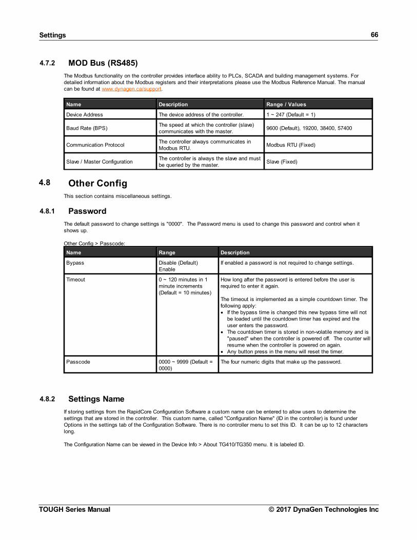
Settings 66
© 2017 DynaGen Technologies IncTOUGH Series Manual
4.7.2 MOD Bus (RS485)
The Modbus functionality on the controller provides interface ability to PLCs, SCADA and building management systems. Fordetailed information about the Modbus registers and their interpretations please use the Modbus Reference Manual. The manualcan be found at www.dynagen.ca/support.
Name Description Range / Values
Device Address The device address of the controller. 1 ~ 247 (Default = 1)
Baud Rate (BPS)The speed at which the controller (slave)communicates with the master.
9600 (Default), 19200, 38400, 57400
Communication ProtocolThe controller always communicates inModbus RTU.
Modbus RTU (Fixed)
Slave / Master ConfigurationThe controller is always the slave and mustbe queried by the master.
Slave (Fixed)
4.8 Other ConfigThis section contains miscellaneous settings.
4.8.1 Password
The default password to change settings is "0000". The Password menu is used to change this password and control when itshows up.
Other Config > Passcode:
Name Range Description
Bypass Disable (Default)Enable
If enabled a password is not required to change settings.
Timeout 0 ~ 120 minutes in 1minute increments(Default = 10 minutes)
How long after the password is entered before the user isrequired to enter it again.
The timeout is implemented as a simple countdown timer. Thefollowing apply:· If the bypass time is changed this new bypass time will not
be loaded until the countdown timer has expired and theuser enters the password.
· The countdown timer is stored in non-volatile memory and is"paused" when the controller is powered off. The counter willresume when the controller is powered on again.
· Any button press in the menu will reset the timer.
Passcode 0000 ~ 9999 (Default =0000)
The four numeric digits that make up the password.
4.8.2 Settings Name
If storing settings from the RapidCore Configuration Software a custom name can be entered to allow users to determine thesettings that are stored in the controller. This custom name, called "Configuration Name" (ID in the controller) is found underOptions in the settings tab of the Configuration Software. There is no controller menu to set this ID. It can be up to 12 characterslong.
The Configuration Name can be viewed in the Device Info > About TG410/TG350 menu. It is labeled ID.

Settings 67
© 2017 DynaGen Technologies IncTOUGH Series Manual
4.8.3 Process Control
The Process Control feature has two different control methods: Main-In and Main-Out. The Main-In maintains a reservoir level bycontrolling the flow of fluid into the reservoir. The Main-Out maintains a reservoir level by controlling the flow of fluid from thereservoir. It does this by regulation the speed of the engine over the J1939 CAN bus.
The controller reads the sensor value from selected Auxiliary Sensor input (1~5), compares the input value with the set-point, andthen, based on an algorithm, increments or decrements the speed (RPM) by a certain amount to maintain the desired set-pointoutside of the dead-band area. Control pauses inside the dead-band area. If the sensor input goes beyond a minimum or maximumvalue, the algorithm will pause and the RPM will be maintained at a minimum or maximum value.
The algorithm is a fuzzy logic type control with a dead band and a minimum / maximum saturation. The user sets theaggressiveness of the control with the Gain setting and the response time of the control with the Delay setting.
(Other Config > Process Control menu)
Name Range Description
Closed Loop > System (ControlType)
DisabledMain-In (Maintain In)Main-Out (Maintain Out)
Main-In controls the level when pumping fluid into a reservoir. Main-Out controls the level while pumping fluid out of the reservoir.
Closed Loop > Sensor In(Sensor Input)
AUX-1AUX-2AUX-3AUX-4AUX-5 (Transducer)
The Auxiliary Sensor Input function that is providing feedback onthe reservoir level. Aux-5 refers to the Transducer under theApplication menu.
Closed Loop > Delay 1 ~ 30 s in 0.1 sincrements
The sampling time of the control algorithm.
Closed Loop > Gain 1 ~ 30 in 0.1 increments The amount to increment or decrement the RPM when the sensedvalue is outside of the dead-band.
Setpoints > Main-In (Maintain InSetpoint)
1 ~ 900 in 0.1 increments The level set-point to attempt to maintain. Only applies if Systemis set to In-Keep.
Setpoints > Main-Out (MaintainOut Setpoint)
1 ~ 900 in 0.1 increments The level set-point to attempt to maintain. Only applies if Systemis set to Out-Keep
Setpoints > Deadband+ (HighDeadband)
1 ~ 30 in 0.1 increments The high limit of the dead-band.
Setpoints > Deadband- (LowDeadband)
1 ~ 30 in 0.1 increments The low limit of the dead-band.
Thresholds > High Edge (HighLimit)
1 ~ 900, 0.1 increments The high saturation. The maximum level at which the RPM controlis fixed.
Thresholds > Low Edge (LowLimit)
1 ~ 900, 0.1 increments The low saturation. The minimum level at which the RPM control isfixed.
Thresholds > Max RPM (MaxLimit RPM)
500 ~ 4000 RPM in 1RPM increments
The fixed RPM that should be used when the level rises above theHigh Edge.
Thresholds > Min RPM (LowLimit RPM)
500 ~ 4000 RPM in 1RPM increments
The fixed RPM that should be used when the level falls below theLow Edge.

Troubleshooting 68
© 2017 DynaGen Technologies IncTOUGH Series Manual
5 Troubleshooting
If you are having issues with your controller, please refer to the table below for a solution before contacting technical support.
Issue Solution
Engine starts but the crank outputdoes not turn off
The controller is not receiving a speed signal. 1. Verify the Sensors -> Engine Speed -> Signal Source setting is set correctly.2. Verify the Timers -> Engine Logic -> RPM Disconnect setting is set correctly.3. Ensure the correct wiring to the controller. For magnetic pickup, Speed Sensing
A and B terminals are used. For generator voltage, the AC voltage connectionsare used.
Sensor always displays its lowest orhighest value
The sensor could either be open (not connected) or shorted to ground. Verify yourconnections and ensure the correct sender table is loaded.
DYNAGEN can be contacted by any of the methods below. Technical support is offered Monday - Friday, 8:00am - 4:00pm (EST).If you are unable to contact one of our engineers, please leave a message and they will return your call as soon as possible.
Type Information
Website www.dynagen.ca/support
Email [email protected]
Phone Number (902) 406-0133
Twitter @DynaGenTech
Facebook www.facebook.com/DYNAGEN
Address3 Spectacle Lake Drive, Unit B105Dartmouth, NS B3B1W8, Canada