TG2 Mobilian Draft Text - IEEE-SA - Working...
26
July, 2001 IEEE P802.15-01300r1 IEEE P802.15 Wireless Personal Area Networks Project IEEE P802.15 Working Group for Wireless Personal Area Networks (WPANs) Title TG2 Mobilian Draft Text Date Submitt ed [5 July, 2001] Source [Jim Lansford, Adrian P Stephens] [Mobilian Corporation] [7431 NW Evergreen Pkwy, Hillsboro, OR 97124, USA] Voice: [ +1 (503) 681-8600 ] Fax: [ ] E-mail: [ [email protected] [email protected] m ] Re: 00308r0P802-15_TG2-Stage0_PHY_Model.ppt 00360r0P802-15_TG2-Mobilian-coexistence-proposal.ppt 01164r0P802-15_TG2-Mobilian-Symbol-802.11-Bluetooth.ppt 01172r0P802-15_TG2-Mobilian-Symbol-summary.ppt Abstrac t <<<missing phy bits>>> This document defines the Mobilian parts of the mechanism for MAC-level collaborative coexistence between 802.11 and 802.15.1. A top-level structure is defined showing the relationship of the TDMA and MEHTA parts of the coexistence mechanism. The MEHTA technique is described in detail. Each packet transmit request is allowed or denied by MEHTA according to the Submission Page 1 Jim Lansford, Adrian P Stephens, Mobilian Corporation
Transcript of TG2 Mobilian Draft Text - IEEE-SA - Working...
July, 2001 IEEE P802.15-01300r1
IEEE P802.15Wireless Personal Area Networks
Project IEEE P802.15 Working Group for Wireless Personal Area Networks (WPANs)
Title TG2 Mobilian Draft Text
Date Submitted
[5 July, 2001]
Source [Jim Lansford, Adrian P Stephens][Mobilian Corporation][7431 NW Evergreen Pkwy, Hillsboro, OR 97124, USA]
Voice: [ +1 (503) 681-8600 ]Fax: [ ]E-mail:[ [email protected]@mobilian.com ]
Re: 00308r0P802-15_TG2-Stage0_PHY_Model.ppt00360r0P802-15_TG2-Mobilian-coexistence-proposal.ppt01164r0P802-15_TG2-Mobilian-Symbol-802.11-Bluetooth.ppt01172r0P802-15_TG2-Mobilian-Symbol-summary.ppt
Abstract <<<missing phy bits>>>
This document defines the Mobilian parts of the mechanism for MAC-level collaborative coexistence between 802.11 and 802.15.1. A top-level structure is defined showing the relationship of the TDMA and MEHTA parts of the coexistence mechanism. The MEHTA technique is described in detail. Each packet transmit request is allowed or denied by MEHTA according to the known state of the other protocol stack. The decision is based on defining priorities for packet types and activities within the protocol stacks.
Purpose This document contains draft text for those clauses of the 802.15.2 recommended practice that are to be provided by Mobilian Corporation.
Notice This document has been prepared to assist the IEEE P802.15. It is offered as a basis for discussion and is not binding on the contributing individual(s) or organization(s). The material in this document is subject to change in form and content after further study. The contributor(s) reserve(s) the right to add, amend or withdraw material contained herein.
Release The contributor acknowledges and accepts that this contribution becomes the
Submission Page 1 Jim Lansford, Adrian P Stephens,
Mobilian Corporation

July, 2001 IEEE P802.15-01300r1
property of IEEE and may be made publicly available by P802.15.
Submission Page 2 Jim Lansford, Adrian P Stephens,
Mobilian Corporation

July, 2001 IEEE P802.15-01300r1
Note, comments by the author that are not intended to be part of the final document are introduced by: “[Mobilian – “.[ed – this version contains changes made to r0 during review at the July 2001 TG2 meetings].
Clause 6 Physical Layer Models
[ed – Open issues:
should we present this as a quasi-analytic and brute-force simulation? AI:Cyphershould source code be available for both/either of the model? (AI: Mobilian)
]
6.2 IEEE 802.11b (Wi-Fi) in the presence of IEEE 802.15.1 (Bluetooth)[Mobilian – the outline shows separate sections for 6.21 and 6.43. However, the presentation naturally follows the calculation of mutual interference as presented in this section. It could be re-organized (with some necessary duplication) to fit the original outline if that is deemed necessary by whatever powers that be!).]
6.1.1 IntroductionThis section describes a model that allows the PER to be calculated for 802.11b and 802.15.1 packets in the presence of mutual interference.[Perhaps re-structure so that the POS is at a higher layer. Two subordinate models: analytic and simulation . New intro to say calculating BER. ]
This is the so-called analytic “phase 0” model – using signal, noise and interference power levels at the receiver to calculate BER. Later phase models may use sophisticated baseband models to obtain more accurate BER values.
6.1.2 Model Concepts[move up to “structure” section]The most powerful simplifying concept in this model is the period of stationaritystability (POS). This is the period over which the transmissions of the devices being modeled do not change.
By definition, during the POS the transmit power and modulation type does not change, and it is also assumed that the position of the devices (and hence link loss) is constant. So receiving nodes experience constant signal, noise and interference powers from which a BER value can be calculated.
Consider the example shown in Figure 1. Here an 802.15.1 device transmits two packets. An 802.11b device transmits a single PPDU using 11Mbps modulation type for the PSDU. The start
Submission Page 3 Jim Lansford, Adrian P Stephens,
Mobilian Corporation

July, 2001 IEEE P802.15-01300r1
of the PLCP header overlaps the end of the first 802.15.1 packet. The end of the PSDU overlaps the start of the second 802.15.1 packet. There are six periods of stability. Note that a new POS starts at the end of the PLCP header because the modulation type changes at this point.
Figure 1 - Example showing Periods of Stability
The BER calculated by the model is constant during the POS.The physical layer model calculates any bit errors at each receiver for a single POS.
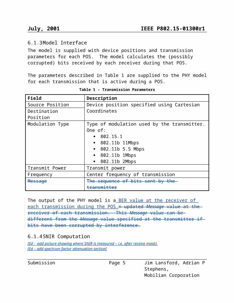
6.1.3 Model InterfaceThe model is supplied with device positions and transmission parameters for each POS. The model calculates the (possibly corrupted) bits received by each receiver during that POS.
The parameters described in Table 1 are supplied to the PHY model for each transmission that is active during a POS.
Table 1 - Transmission Parameters
Field DescriptionSource Position Device position specified using Cartesian CoordinatesDestination PositionModulation Type Type of modulation used by the transmitter. One of:
802.15.1 802.11b 11Mbps 802.11b 5.5 Mbps 802.11b 1Mbps 802.11b 2Mbps
Transmit Power Transmit powerFrequency Center frequency of transmissionMessage The sequence of bits sent by the transmitter
The output of the PHY model is a BER value at the receiver of each transmission during the POS.n updated Message value at the receiver of each transmission. This Message value can be
Submission Page 4 Jim Lansford, Adrian P Stephens,
Mobilian Corporation
July, 2001 IEEE P802.15-01300r1
different from the Message value specified at the transmitter if bits have been corrupted by interference.
6.1.4 SNIR Computation[Ed - add picture showing where SNIR is measured – i.e. after receive mask].[Ed – add spectrum factor attenuation section]
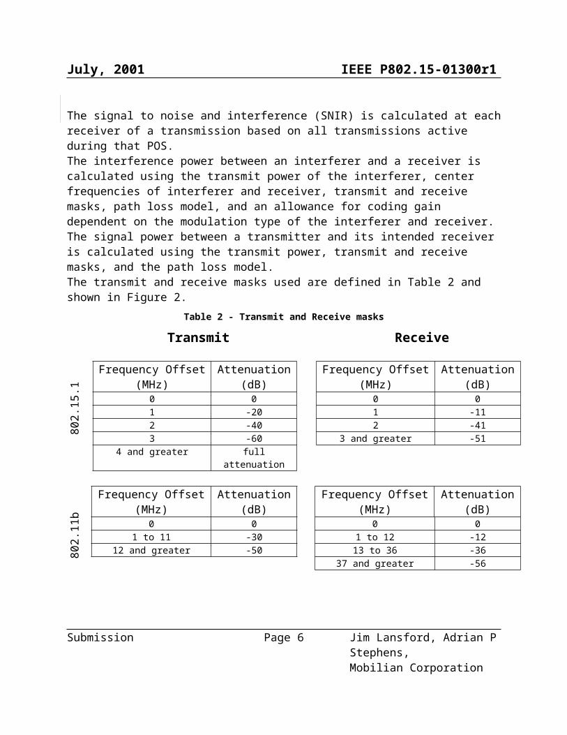
The signal to noise and interference (SNIR) is calculated at each receiver of a transmission based on all transmissions active during that POS.The interference power between an interferer and a receiver is calculated using the transmit power of the interferer, center frequencies of interferer and receiver, transmit and receive masks, path loss model, and an allowance for coding gain dependent on the modulation type of the interferer and receiver.The signal power between a transmitter and its intended receiver is calculated using the transmit power, transmit and receive masks, and the path loss model.The transmit and receive masks used are defined in Table 2 and shown in Figure 2.
Table 2 - Transmit and Receive masks
Transmit Receive
802.
15.1
Frequency Offset (MHz)
Attenuation (dB)
0 01 -202 -403 -60
4 and greater full attenuation
Frequency Offset (MHz)
Attenuation (dB)
0 01 -112 -41
3 and greater -51
802.
11b
Frequency Offset (MHz)
Attenuation (dB)
0 01 to 11 -30
12 and greater -50
Frequency Offset (MHz)
Attenuation (dB)
0 01 to 12 -1213 to 36 -36
37 and greater -56
Submission Page 5 Jim Lansford, Adrian P Stephens,
Mobilian Corporation
July, 2001 IEEE P802.15-01300r1
Transmit Receive
802.
15.1
802.
11b
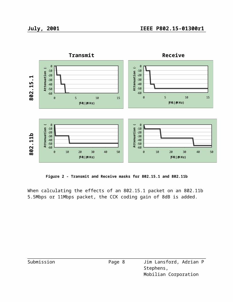
Figure 2 - Transmit and Receive masks for 802.15.1 and 802.11b
When calculating the effects of an 802.15.1 packet on an 802.11b 5.5Mbps or 11Mbps packet, the CCK coding gain of 8dB is added.
Submission Page 6 Jim Lansford, Adrian P Stephens,
Mobilian Corporation
-60-50-40-30-20-10
0
0 5 10 15
|f-fc| (MHz)
Atte
nuat
ion
(dB
)
-60-50-40-30-20-10
0
0 5 10 15
|f-fc| (MHz)
Atte
nuat
ion
(dB
)
-60-50-40-30-20-10
0
0 10 20 30 40 50
|f-fc| (MHz)
Atte
nuat
ion
(dB
)
-60-50-40-30-20-10
0
0 10 20 30 40 50
|f-fc| (MHz)
Atte
nuat
ion
(dB
)
July, 2001 IEEE P802.15-01300r1
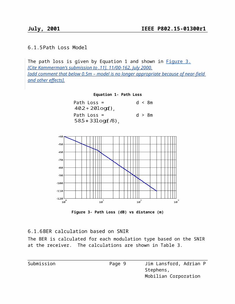
6.1.5 Path Loss Model
The path loss is given by Equation 1 and shown in Figure 3.[Cite Kammerman’s submission to .11]. 11/00-162, July 2000.[add comment that below 0.5m – model is no longer appropriate because of near-field and other effects].
Equation 1- Path Loss
Path Loss = , d < 8mPath Loss = , d > 8m
Figure 3- Path Loss (dB) vs distance (m)
6.1.6 BER calculation based on SNIRThe BER is calculated for each modulation type based on the SNIR at the receiver. The calculations are shown in Table 3.
Table 3 - BER Calculations
Modulation Type BER802.15.1 1
[Ed – this might be for orthogonal FSK. Ask Josie]
1 Modeled as non-coherent FSK
Submission Page 7 Jim Lansford, Adrian P Stephens,
Mobilian Corporation
July, 2001 IEEE P802.15-01300r1
802.11b 1Mbps[Ed – need to validate references for this, ask Josie]
802.11b 2Mbps802.11b 5.5 and 11 Mbps See below
The Q function is defined in section 6.1.6.3.
6.1.6.1 802.11b 5.5 Mbps BER Calculation [Ed – change PEW to SER (symbol error rate). Change codewords to symbols][Ed – check that there is no normalization. Is this a bound?]For 802.11b 5.5 Mbps, the symbolcodeword error rateprobability, SERPEW5.5, is given by:
[Ed – do we have a reference for this? Look at .11b standard to align terminology]
As each symbolcodeword encodes 4 bits, the effective BER is
6.1.6.2 802.11b 11 Mbps BER Calculation For 802.11b 11 Mbps, the symbolcodeword error rateprobability, SERPEW11 is given by:
As each symbolcodeword encodes 8 bits, the effective BER is
6.1.6.3 Q Function Definition The Q function is defined as the area under the tail of the Gaussian probability density function with zero mean and unit variance..
6.1.6.4 SNIR Limits The simulation is simplified by assuming that above a certain SNIR the BER is effectively zero and below a certain SNIR the BER is effectively 0.5. These limits are defined in Table 4.
Table 4 - Assumed Limits on SNIR
Receiver Upper limit on SNIR Lower limit on SNIR802.11b 10dB -3dB802.15.1 20dB 1dB
Submission Page 8 Jim Lansford, Adrian P Stephens,
Mobilian Corporation
July, 2001 IEEE P802.15-01300r1
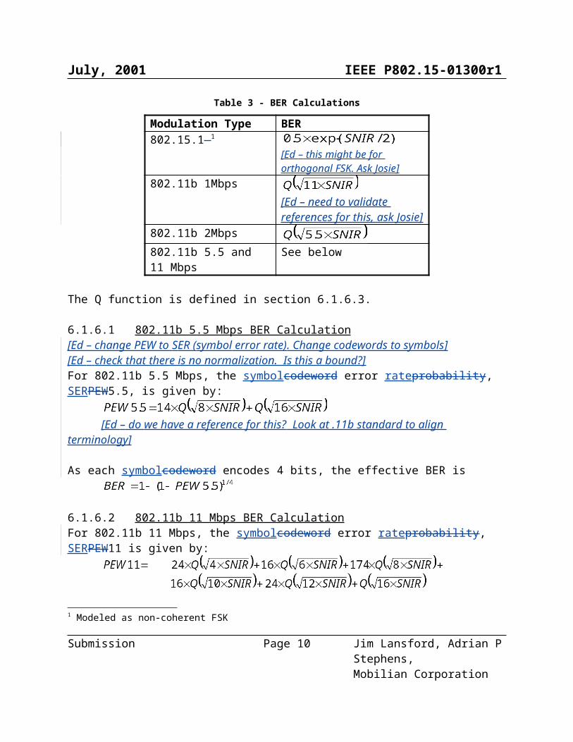
6.1.6.5 BER versus SNIR Results
Figure 4 shows the results of calculating BER for SNIR values in the range –15 to 20dB for each modulation type 2. [Ed – need to define where SNIR is referenced. Needs to be clear where it is measured – after the receive filter.]
Figure 4 - BER results
6.1.7 Simulation of bit errorsGiven the BER at each receiver, the received message is determined by inverting bits in the transmitted message based on the calculated BER for that transmission.
Each bit corruption is calculated independently. The probability of inverting a bit has a uniform distribution with the specified BER as the mean.
These received (and possibly corrupted) Message fields, form the output of the PHY-layer model.
2 The results for 802.11b 11Mbps do not show calculated values for SNIR < -2dB due to limitations of the tools used.
Submission Page 9 Jim Lansford, Adrian P Stephens,
Mobilian Corporation
1.0E-10
1.0E-09
1.0E-08
1.0E-07
1.0E-06
1.0E-05
1.0E-04
1.0E-03
1.0E-02
1.0E-01
1.0E+00
-15 -10 -5 0 5 10 15 20
SNIR (dB)
BER
802.11b 1Mbps802.11b 2Mbps802.15.1802.11b 5.5Mbps802.11b 11Mbps
July, 2001 IEEE P802.15-01300r1
Submission Page 10 Jim Lansford, Adrian P Stephens,
Mobilian Corporation

July, 2001 IEEE P802.15-01300r1
Clause 14 Collaborative Mechanism – IEEE 802.11 and 802.15.1 (Bluetooth)
[Mobilian - The ordering and numbering of these sections is a draft proposal by Mobilian subject to confirmation by Symbol.]
6.2 Collaborative Mechanism – IEEE 802.11 and 802.15.1
6.2.1 Introduction (Informative)The collaborative mechanism provides coexistence of IEEE 802.11 and 802.15.1 3 by sharing information between collocated 802.11 and 802.15.1 stacks and locally controlling transmissions to avoid interference. No new on-air signaling is required. This mechanism is interoperable with devices that do not include it.
Two techniques are defined: TDMA and MEHTA 4. (fix footnote)
In the TDMA technique, the 802.11 AP and 802.15.1 master are collocated. This device allows the 802.11 and 802.15.1 networks to transmit alternately, defining the time that each has access to the medium. The TDMA technique can support multiple 802.15.1 piconets. It cannot support 802.15.1 SCO links.
In the MEHTA technique, the 802.11 STA and 802.15.1 node are collocated. There is no need to be either the 802.11 AP or the 802.15.1 master. Each attempt to transmit by either the 802.11 or the 802.15.2 stack is submitted to MEHTA for approval. MEHTA can deny a transmit request that would result in collision. The MEHTA technique can support 802.15.1 SCO links.
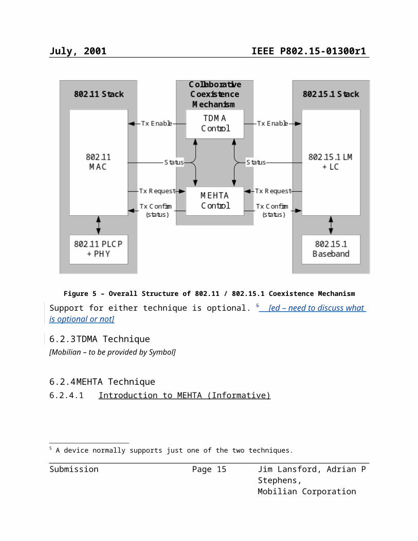
6.2.2 Overall StructureFigure 5 shows the overall structure of the mechanism.
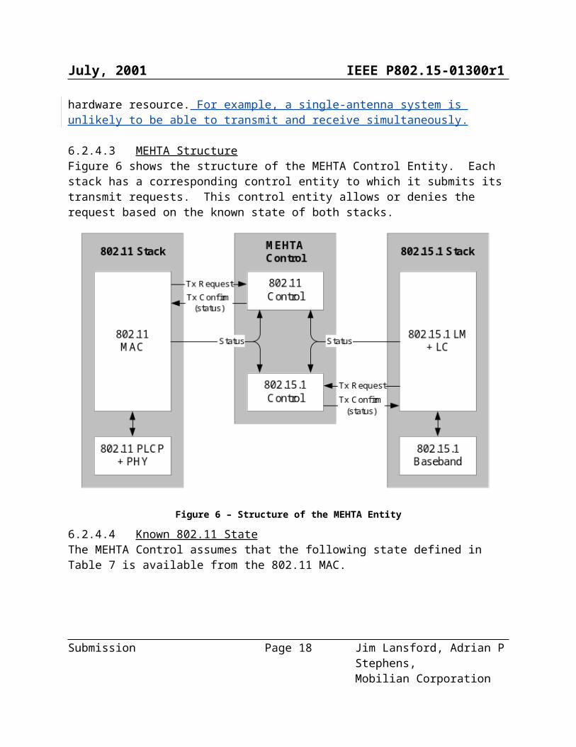
The 802.11 MAC and 802.15.1 LM + LC entities provide status information to the TDMA control and MEHTA control entities.
The TDMA control entity provides a transmit enable (Tx Enable) signal to each stack. This is a continuous signal that gates whether each stack can start a new packet transmission.
The MEHTA control entity receives a per-transmission transmit request (Tx Request) and issues a per-transmission transmit confirm (Tx Confirm) to each stack to indicate whether the
3 Although this document consistently references 802.15.1, not Bluetooth ™, the mechanism is equally applicable to both 802.15.1 and Bluetooth.4 MEHTA is the Hebrew word for “Conductor”.
Submission Page 11 Jim Lansford, Adrian P Stephens,
Mobilian Corporation
July, 2001 IEEE P802.15-01300r1
transmission can proceed. The Tx Confirm carries a status value that is one of: allowed or denied. The Tx Request and Tx Confirm are discreet signals exchanged for every packet transmission attempt.
Figure 5 – Overall Structure of 802.11 / 802.15.1 Coexistence Mechanism
Support for either technique is optional. 5 [ed – need to discuss what is optional or not]
6.2.3 TDMA Technique[Mobilian – to be provided by Symbol]
6.2.4 MEHTA Technique6.2.4.1 Introduction to MEHTA (Informative) The MEHTA control entity provides per-packet 6 authorization of all transmissions.
5 A device normally supports just one of the two techniques.6 The word packet is used here to mean an 802.11 MPDU or an 802.15.1 baseband packet.
Submission Page 12 Jim Lansford, Adrian P Stephens,
Mobilian Corporation
July, 2001 IEEE P802.15-01300r1
MEHTA uses its knowledge of the duration of 802.11 activity and future 802.15.1 activity a number of slots into the future to predict collisions. When a collision would occur, MEHTA prioritizes transmissions based on simple rules that depend on packet types.
Note, this model is a logical model that executes in zero time. An implementation needs to be cleverer than that. (reword)
6.2.4.2 Known Physical-Layer Characteristics
[make sure we use .11b, not .11]The 802.11 PHY operates on a known static channel. The 802.15.1 PHY hops following a known hopping pattern. At any time, the 802.15.1 signal can be inside or outside the pass-band[add explanation of pass-band – reference David’s definitions] of the 802.11 PHY. These are the in-band and out-of-band cases, and they affect the probability of a collision 7.
The different collision cases are summarized in Table 5.
Table 5 – Collision Cases as a Function of Local Activities
Local 802.11 Activity
Local 802.15.1 ActivityTransmit Receive
In-band Out-of-band In-band Out-of-bandTransmit Transmit None Transmit-Receive
or NoneTransmit-
Receive or NoneReceive Transmit-
Receive or NoneTransmit-Receive
or NoneReceive None
The different collision types are defined in Table 6.Table 6 - Definition of Collision Types
Collision Type DefinitionTransmit Both stacks are transmitting in-band. One or both of the packets will be
received with errors.Receive Both stacks are receiving in-band. One or both of the packets will be received
with errors.Transmit-Receive
One stack is transmitting and the other is simultaneously receiving. The received packet is received with errors.
None Any co-incidence of activity in the two stacks does not increase the error rate.
7 A collision occurs when packets from the 802.11 and 802.15.1 are transmitted simultaneously resulting in the loss of one or both packets.
Submission Page 13 Jim Lansford, Adrian P Stephens,
Mobilian Corporation
July, 2001 IEEE P802.15-01300r1
In the case of “Transmit-Receive or None” collisions, whether there is a collision or not depends on a number of PHY-related parameters that can include: transmit power, received signal strength and the difference between 802.11 and 802.15.1 center frequencies.An implementation predicts the difference between these collision outcomes based on its knowledge of the operating parameters of its PHY. This section does not attempt to standardize that decision. So, based on PHY-layer parameters, an implementation predicts whether a collision occurs.
Implementation constraints can also introduce addition types of “collision” based on simultaneous conflicting demands for hardware resource. For example, a single-antenna system is unlikely to be able to transmit and receive simultaneously.
6.2.4.3 MEHTA Structure Figure 6 shows the structure of the MEHTA Control Entity. Each stack has a corresponding control entity to which it submits its transmit requests. This control entity allows or denies the request based on the known state of both stacks.
Figure 6 – Structure of the MEHTA Entity
6.2.4.4 Known 802.11 State
Submission Page 14 Jim Lansford, Adrian P Stephens,
Mobilian Corporation
July, 2001 IEEE P802.15-01300r1
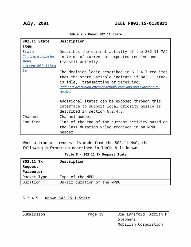
The MEHTA Control assumes that the following state defined in Table 7 is available from the 802.11 MAC.
Table 7 - Known 802.11 State
802.11 State Item DescriptionState[find better name for state]current802.11State
Describes the current activity of the 802.11 MAC in terms of current or expected receive and transmit activity.
The decision logic described in 6.2.4.7 requires that the state variable indicate if 802.11 stack is idle, transmitting or receiving.[add note describing effect of actually receiving and expecting to receive]
Additional states can be exposed through this interface to support local priority policy as described in section 6.2.4.8.
Channel Channel numberEnd Time Time of the end of the current activity based on the last duration value
received in an MPDU header
When a transmit request is made from the 802.11 MAC, the following information described in Table 8 is known.
Table 8 - 802.11 Tx Request State
802.11 Tx Request Parameter
Description
Packet Type Type of the MPDUDuration On-air duration of the MPDU
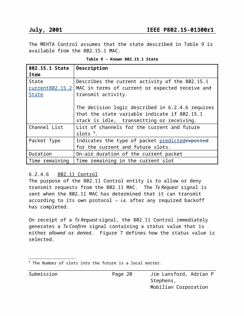
6.2.4.5 Known 802.15.1 State The MEHTA Control assumes that the state described in Table 9 is available from the 802.15.1 MAC.
Table 9 - Known 802.15.1 State
802.15.1 State Item DescriptionStatecurrent802.15.2State
Describes the current activity of the 802.15.1 MAC in terms of current or expected receive and transmit activity.
The decision logic described in 6.2.4.6 requires that the state variable indicate if 802.15.1 stack is idle, transmitting or receiving.
Channel List List of channels for the current and future slots 8.Packet Type Indicates the type of packet predictedexpected for the current and future
8 The Number of slots into the future is a local matter.
Submission Page 15 Jim Lansford, Adrian P Stephens,
Mobilian Corporation

July, 2001 IEEE P802.15-01300r1
slots.Duration On-air duration of the current packetTime remaining Time remaining in the current slot
6.2.4.6 802.11 Control The purpose of the 802.11 Control entity is to allow or deny transmit requests from the 802.11 MAC. The Tx Request signal is sent when the 802.11 MAC has determined that it can transmit according to its own protocol – i.e. after any required backoff has completed.
On receipt of a Tx Request signal, the 802.11 Control immediately generates a Tx Confirm signal containing a status value that is either allowed or denied. Figure 7 defines how the status value is selected.
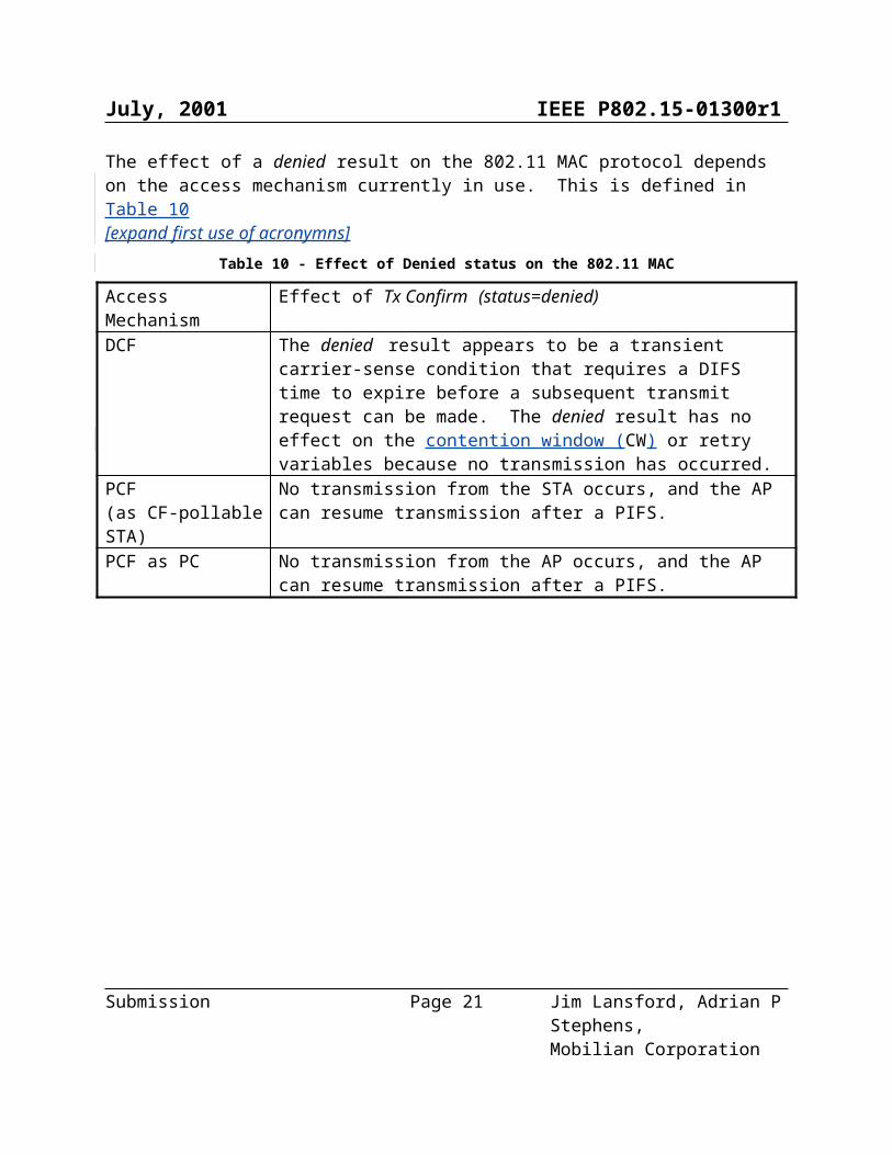
The effect of a denied result on the 802.11 MAC protocol depends on the access mechanism currently in use. This is defined in Table 10[expand first use of acronymns]
Table 10 - Effect of Denied status on the 802.11 MAC
Access Mechanism Effect of Tx Confirm (status=denied)DCF The denied result appears to be a transient carrier-sense condition that
requires a DIFS time to expire before a subsequent transmit request can be made. The denied result has no effect on the contention window (CW) or retry variables because no transmission has occurred.
PCF(as CF-pollable STA)
No transmission from the STA occurs, and the AP can resume transmission after a PIFS.
PCF as PC No transmission from the AP occurs, and the AP can resume transmission after a PIFS.
Submission Page 16 Jim Lansford, Adrian P Stephens,
Mobilian Corporation
July, 2001 IEEE P802.15-01300r1
Figure 7 - Decision Logic for 802.11 Tx Request
Table 11 defines the conditions examined by the decision logic.
Submission Page 17 Jim Lansford, Adrian P Stephens,
Mobilian Corporation
July, 2001 IEEE P802.15-01300r1
Table 11 - Conditions Examined by 802.11 Tx Request Decision Logic
Condition DefinitionCurrent collision There is a transmit or transmit-receive collision between
the current 802.15.1 activity and the 802.11b transmit request
Future collision There is a transmit or transmit-receive collision between the 802.15.1 activity scheduled for a future slot and the current 802.11 Tx Request. For a collision to occur in a slot, the requested 802.11 transmit activity must continue until at least the start of that slot.
802.15.1 current slot priority >802.11 packet priority
The priority of the current 802.15.1 activity has greater priority than the 802.11 packet. See section 6.2.4.8.
802.15.1 future slot priority >802.11 packet priority
The priority of the colliding future 802.15.1 activity has greater priority than the 802.11 packet. 6.2.4.8.
Is 802.15.1 currently transmitting? The 802.15.1 known state is in a transmitting state.
6.2.4.7 802.15.1 Control In response to a Tx Request signal, the 802.15.1 control immediately generates a Tx Confirm signal containing a status value that is either allowed or denied. Figure 8 defines how the status value is selected.
The effect of the denied result on the 802.15.1 stack is to prevent 802.15.1 transmission during the whole slot (or slot half in the case of scan sequences).
Submission Page 18 Jim Lansford, Adrian P Stephens,
Mobilian Corporation
July, 2001 IEEE P802.15-01300r1
Figure 8 - Decision Logic for 802.15.1 Tx Request
Table 12 defines the conditions examined in the execution of this decision logic.
Submission Page 19 Jim Lansford, Adrian P Stephens,
Mobilian Corporation
July, 2001 IEEE P802.15-01300r1
Table 12- Conditions Examined by 802.15.1 Tx Request Decision Logic
Condition DefinitionResponse or SCO? True if the Tx Request packet type is Slave ACL, ID, FHS
or SCOCollision? True if a transmit or transmit-receive collision between the
802.15.1 transmit request and the current state of the 802.11 stack
Slave Slot Collision? True if a transmit-receive collision between the slave response to the 802.15.1 transmit request and the current state of the 802.11 stack
802.11 current state priority >802.15.1 packet priority ?
The priority of the 802.11 current state is greater than the 802.15.1 Tx Request packet priority. See section 6.2.4.8.
6.2.4.8 Priority Comparisons The decision logic that allows or denies a packet transmit request uses a priority comparison between the state of the requested transmit packet and the known state of the other protocol stack.
An implementation defines priority values for each separate state value exposed by its protocol stack, and for each transmit packet type.
6.2.4.8.1 Recommended Priority Comparisons An 802.15.1 SCO packet should have a higher priority than 802.11 DATA MPDUs.An 802.11 ACK MPDU should have a higher priority than all 802.15.1 packets.Other priority comparisons are a implementation-specificlocal matter.
6.2.4.8.2 Maintaining QoS A device can optionally monitor QoS by defining metrics (such as PER and delay) per protocol stack. It can use these metrics to bias its priorities in order to meet locally-defined fairness criteria.
In the case of an 802.11e stack, the device can record these metrics per traffic class and bias its priorities in order to meet known per traffic class QoS commitments.
Note, an implementation may need additional communication not shown here to decide whether to admit a connection-setup with particular QoS requirements, given knowledge of QoS commitments in the other protocol stack.
6.2.4.8.3 Maintaining SCO QoS
Submission Page 20 Jim Lansford, Adrian P Stephens,
Mobilian Corporation
July, 2001 IEEE P802.15-01300r1
An implementation can optionally attempt to maintain SCO QoS so as not to exceed some level of SCO packet loss. It does this by monitoring the SCO PER and comparing with a threshold. The priority of the SCO packet is increased when the SCO PER is above the threshold.
Submission Page 21 Jim Lansford, Adrian P Stephens,
Mobilian Corporation


![contenthub.bvsd.org Course... · Web viewDRAFT. DRAFT. DRAFT. DRAFT. DRAFT. DRAFT. DRAFT. DRAFT. DRAFT. DRAFT. DRAFT. DRAFT. 12/28/2015BVSD Curriculum Essentials32 [Course Name]](https://static.fdocuments.net/doc/165x107/5e38c5b23f41ba01b81b757e/course-web-view-draft-draft-draft-draft-draft-draft-draft-draft-draft.jpg)