TFE 731 Chap 72 (1)
38
Garret TFE 731 Turbofan Engine (CAT C) CHAPTER 72 Page 1 of 38 FOR TRAINING PURPOSES ONLY © TFE 731 - ISSUE 2, 2010
Transcript of TFE 731 Chap 72 (1)

Garret TFE 731 Turbofan Engine (CAT C)
CHAPTER 72
Page 1 of 38 FOR TRAINING PURPOSES ONLY © TFE 731 - ISSUE 2, 2010
Garret TFE 731 Turbofan Engine (CAT C)
CHAPTER 72
Page 2 of 38 FOR TRAINING PURPOSES ONLY © TFE 731 - ISSUE 2, 2010
INTRODUCTION
0 TABLE OF CONTENTS
1 Introduction 3 2 Model Numbering 4 3 Model Comparison 5 4 Newton’s Laws 6 5 The Gas Turbine Engine 7 6 Power Conversion 8 7 TFE 731 Engine 9 8 Spool Identification 10 9 Bypass Ratio 11 10 TFE 731 Modular Concept 12 11 Fan Spinner and Spinner Support Installation 13 12 Fan Rotor Assembly Installation –2/-3/-4 Engines 14 13 Fan Rotor Assembly Installation –5 Engine 15 14 Fan Area 16 14.1 Description 16 15 Fan Area 17 15.1 Engine installation differences 17 16 Planetary Gear Assembly 18 17 Compressor Zone 19 18 High Pressure Group 20 19 Combustion Section 21 20 Combustion and Turbine Section 22 21 High Pressure Turbine 23 22 Low Pressure (LP) Turbine Module 24 23 Low Pressure Turbine 25 24 Thrust and Exhaust Nozzle 26 25 Mixer Nozzle Installation 27 26 Curvic Couplings 28 27 Main Engine Bearings 29 28 Labyrinth Seals 30 29 Airflow Stations 31 30 Gearbox Module 32

Garret TFE 731 Turbofan Engine (CAT C)
CHAPTER 72
Page 3 of 38 FOR TRAINING PURPOSES ONLY © TFE 731 - ISSUE 2, 2010
ENGINE
1 INTRODUCTION The TFE731 engine is a two-spool engine with a single-stage gear driven fan. The fan is driven by the low pressure spool through a planetary gear system to provide an approximate 2-to-1 speed reduction. The low pressure spool consists of a four-stage axial compressor and is driven, along with the fan, by a three-stage axial turbine. The high pressure spool consists of a single-stage centrifugal compressor driven by a single-stage axial turbine. The engine and aircraft accessories are driven by the HP spool through the accessory gearbox that is located at the lower part of the engine. The combustion section of the engine consists of a single annular, reverse flow combustor, twelve fuel nozzles, and two electrical igniters. Fuel control for the engine is managed by a hydro mechanical/ electronic system which provides acceleration and deceleration fuel schedules, automatic power changes with ambient condition, over speed protection, proportional thrust with power lever position and surge control. Engine operation is monitored and controlled by an electronic engine control with inputs from ambient temperature and pressure, power lever angle, high pressure and low pressure rotor speeds and turbine temperature. The TFE731 engine was initially designed to meet the needs of an anticipated new class of 12,000-15,000 pound business aircraft with growth potential to accommodate larger aircraft. The engine was based on the core of the
TSCP700, developed for the DC-10 APU and was conceived as the first of a family of turbofan propulsion engines. With low specific fuel consumption, its design would make it quiet enough to meet noise abatement standards then being incorporated in federal regulations. Certification of the TFE731-2, first production model, came in August 1972, after more than 10,000 hours of test cell and flight test. It was certified at 3,500 pounds thrust.

Garret TFE 731 Turbofan Engine (CAT C)
CHAPTER 72
Page 4 of 38 FOR TRAINING PURPOSES ONLY © TFE 731 - ISSUE 2, 2010
This engine became the propulsion system for the Dassault Falcon 10 and Gates Learjet 35 and 36, introduced into service in 1973. While the Dash 2 was the basic engine in the 731 series, a growth version was a logical follow-on for the business jet market. The next in the series, the Dash 3, was specifically designed as a retrofit engine for the four-engined Lockheed Jetstar. Other models of the Dash 3 followed with improved high-altitude characteristics. The Dash 5 was certified in 1983 followed by the Dash 5A in 1984 and the Dash 5B in 1991. While the Dash 5's use the same core as earlier engines, they have higher fan bypass ratios, a Digital Electronic Engine Control, longer life turbine component and enhanced performance capabilities, the Dash 5's thrust ratings range from 4,300 pounds to 4,750 pounds. The Dash 4 engine was certified in 1991 with a thrust rating of 4,080 pounds of thrust. This engine combined the fan and gearbox of a Dash 3 engine with the compressor, combustion, and turbine sections of the Dash 5 engines. The TFE731 power the majority of business type aircraft operating in the world today. The engine has also been successful as the power plant for several military applications.
2 MODEL NUMBERING Each aircraft manufacturer ordering a TFE731 engine will receive the engine equipped and configured exactly as specified. The model number defines significant features and specification ratings. A breakdown of the model number code is shown here. The TFE731 indicates this is a turbofan engine and is one of the series of 731 engines. The -2 is a series indicator and in conjunction with the type number forms the model number used for FAA certification. The -2-1 indicates the specific thrust rating. For example, TFE731-2 engines are rated from 3230 and 3500 pounds thrust. The -2-1 engine produces 3230 pounds thrust at standard day conditions while the -2-2 engine thrust rating is 3500 pounds.
The letter code at the end of the model number is the equipment code. The equipment identifies the specific accessory configuration as specified by the aircraft manufacturer. This letter code is sometimes referred to as the original equipment manufacturer (OEM) code. A part of the Model Numbering system not shown above is a modifier to the series indicator. For example, the model TFE731-3A is the same as the TFE731-3 except that it incorporates an improved technology fan stage. The -3B is the same as the -3A except that it incorporates improved materials in the turbine stages. The "R" modifier (-3R, -3AR, -3BR) indicates engines that incorporate a performance reserve system.

Garret TFE 731 Turbofan Engine (CAT C)
CHAPTER 72
Page 5 of 38 FOR TRAINING PURPOSES ONLY © TFE 731 - ISSUE 2, 2010
3 MODEL COMPARISON TFE731 engines are used on 19 different aircraft models produced by ten manufacturers. While the specific different models and configurations exceed 25, our emphasis will be based on the four series listed here. The TFE731-2 was the first in the family of 731 turbofans and was initially installed on the Falcon 10 rated at 3230 pounds thrust. Follow-on installations included the Learjet 35/36, rated at 3500 pounds thrust. The TFE731-3 is a growth version of the Dash 2, differs in that the Dash 3’s provide increased thrust ratings (3700 pounds), and incorporates air-cooled high pressure turbine blades. The Dash 3 also offers a slight increase in low pressure rotor speed with an increase in fan inlet total airflow, core airflow and bypass ratio. Specific thrust ratings, design features and construction will be discussed in detail in the following sections. The TFE731-4 utilises the fan and gearbox assembly of the TFE731-3A/B/C for takeoff and climb performance and the compressor, combustor and turbine section of the Dash 5 engine. This marriage brings together two very efficient sections of the 731 family into one engine assembly. The TFE731-5 engine series is also a lightweight, two spool, front-fan engine. The Dash 5 series incorporates recent design developments that increase engine maintainability and thrust ratings. The Dash 5A and 5B engines include a compound core mixer nozzle that acts to further increase thrust. The four series of engines retain considerable commonality in that all feature two spools, a gear-driven front fan, medium bypass ratio and low noise levels. The engines feature a reverse-flow annular combustor to minimise engine length and are modularised for ease of maintenance. In order to examine each model and series engine in detail, a review of gas turbine theory may be appropriate.

Garret TFE 731 Turbofan Engine (CAT C)
CHAPTER 72
Page 6 of 38 FOR TRAINING PURPOSES ONLY © TFE 731 - ISSUE 2, 2010
4 NEWTON’S LAWS A gas turbine engine is an engine designed to convert the heat of fuel into some form of useful power, such as the high speed thrust of a jet. It is basically comprised of two sections: a "gas generator" section and a "power-conversion" section. The gas turbine engine is based upon Newton's Second and Third Laws. Newton's Second Law states, "force equals mass accelerated". That law, combined with Newton's Third Law, "every action has an equal and opposite reaction", provides the basis for gas turbine operation. A good example for the third law is the toy balloon shown here. High pressure air escapes and the balloon moves in the opposite direction. The gas turbine's basic operation is much the same. The "action" is called jet exhaust, and the "reaction" is called thrust. The toy balloon will only move as long as the inside pressure is greater than the outside. Once the inside pressure is gone, the balloon must be refilled. The gas turbine engine takes in air and, with the help of fuel, makes its own high pressure so it can continue to run.

Garret TFE 731 Turbofan Engine (CAT C)
CHAPTER 72
Page 7 of 38 FOR TRAINING PURPOSES ONLY © TFE 731 - ISSUE 2, 2010
5 THE GAS TURBINE ENGINE The portion of the gas turbine engine that creates the force is called the gas generator. The gas generator section consists of three portions. The air mass that the gas turbine uses must be compressed into high pressure through the first portion of the gas generator called the compressor. The incoming air is pulled in and compressed with the high pressure compressor. To get higher pressures, more compressors are added. As the air passes through each stage of compression, the housing becomes smaller and the pressure becomes higher. In order to provide thrust, however, the compressed air must be expanded by the combustion stage. The compressed air contains a large amount of oxygen to provide combustion with a very hot flame. Compressing the air also imparts velocity. The high velocity air must be slowed down to properly mix with fuel and prevent flameout. A simple device called a diffuser does this. The diffuser forms a divergence, reducing the velocity and increasing pressure. The hot gases produced by combustion (second portion of the gas generator) are directed through the turbine nozzle. The turbine nozzle vanes form a convergent duct that increases the velocity to provide the power to drive the turbines. The turbines form the third portion of the gas generator.
Garret TFE 731 Turbofan Engine (CAT C)
CHAPTER 72
Page 8 of 38 FOR TRAINING PURPOSES ONLY © TFE 731 - ISSUE 2, 2010
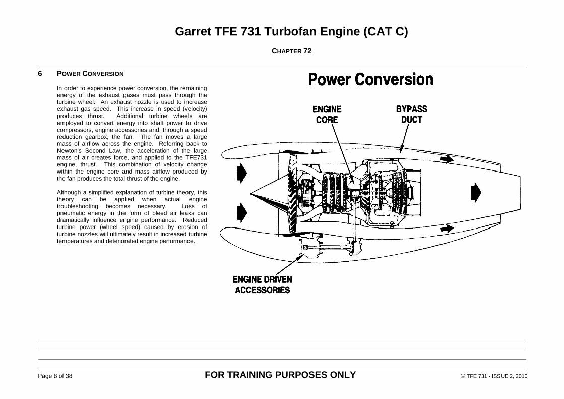
6 POWER CONVERSION In order to experience power conversion, the remaining energy of the exhaust gases must pass through the turbine wheel. An exhaust nozzle is used to increase exhaust gas speed. This increase in speed (velocity) produces thrust. Additional turbine wheels are employed to convert energy into shaft power to drive compressors, engine accessories and, through a speed reduction gearbox, the fan. The fan moves a large mass of airflow across the engine. Referring back to Newton's Second Law, the acceleration of the large mass of air creates force, and applied to the TFE731 engine, thrust. This combination of velocity change within the engine core and mass airflow produced by the fan produces the total thrust of the engine. Although a simplified explanation of turbine theory, this theory can be applied when actual engine troubleshooting becomes necessary. Loss of pneumatic energy in the form of bleed air leaks can dramatically influence engine performance. Reduced turbine power (wheel speed) caused by erosion of turbine nozzles will ultimately result in increased turbine temperatures and deteriorated engine performance.

Garret TFE 731 Turbofan Engine (CAT C)
CHAPTER 72
Page 9 of 38 FOR TRAINING PURPOSES ONLY © TFE 731 - ISSUE 2, 2010
7 TFE 731 ENGINE A spinner and an axial-flow fan are located at the forward end of the engine and are gear-driven by the low pressure spool. The low pressure spool consists of a four-stage axial flow low pressure compressor and a three-stage low pressure turbine, both mounted on a common shaft. The high pressure spool consists of a high pressure single-stage centrifugal compressor and a high pressure single-stage turbine. The high pressure compressor and turbine are mounted on a common shaft. The high pressure spool drives the accessory section. The spool shafts are concentric and the low-pressure spool shaft passes through the high pressure shaft. The fan provides inlet air for the engine compressor and bypasses a large portion of air for noise reduction and additional thrust. Inlet air enters the four-stage low pressure compressor where it is compressed and forced through the interstage diffuser assembly to the single-stage centrifugal high pressure compressor. Air is further compressed by the high pressure compressor and is discharged through a diffuser into a single reverse-flow annular combustion chamber in the turbine section. Here the air is mixed with atomised fuel supplied by twelve duplex fuel nozzles. The two igniter plugs ignite the fuel-air mixture. The resultant combustion gases are directed to the turbine by the transition liner. The turbine section is comprised of a single-stage axial flow high pressure turbine and a three-stage axial flow low pressure turbine. Gases flowing
through the turbine section are exhausted through the thrust and exhaust nozzle. Let us continue our engine construction discussion by examining each section of the engine. The Dash 2 engine will be addressed with the differences specified, if applicable, for the Dash 3, Dash 4, and Dash 5 engines.

Garret TFE 731 Turbofan Engine (CAT C)
CHAPTER 72
Page 10 of 38 FOR TRAINING PURPOSES ONLY © TFE 731 - ISSUE 2, 2010
Terms used throughout this study guide such as forward, rear or aft, upper, lower, left, right, clockwise, counter clockwise, and similar directional references are always determined by standing at the rear of the engine and looking forward, unless stated otherwise (such as "facing the mounting pad" for an accessory drive rotation description).
8 SPOOL IDENTIFICATION The high pressure spool is comprised of a single stage centrifugal compressor driven by a single stage axial flow turbine wheel. This spool, designated N2, is concentric with the low pressure spool, and through a tower shaft arrangement, drives the accessory gearbox. The direction of rotation of the high pressure spool is clockwise. The high pressure compression ratio is 3.5 to 1 for all series engines. Maximum spool speed is 100% RPM. The low pressure spool, designated N1, consists of a four stage axial flow compressor driven by a three stage axial flow turbine. The low pressure turbines also drive the bypass fan through a planetary gear assembly. The low pressure compressor compression ratio is 1.3 to 1 per stage. The low pressure spool direction of rotation is clockwise. Maximum spool speed at 100% RPM is shown in the table below. The planetary gearbox converts the high speed low torque N1 RPM to drive the fan. The planetary gear case will be explored in detail during the engine module discussion later in this volume. Maximum spool speeds at 100% RPM by engine series is:
-2/-3 -4 -5/5A -5B
Fan 11,481 11,655 10,416 10,667
LP Spool 20,688 21,000 21,000 21,000
HP Spool 29,692 29,989 29,692 30,300
Notice that the low pressure (LP) spool turns inside the high pressure (HP) spool. The dotted lines indicate the low pressure spool shaft. The two spools are in no way connected and, as stated, turn at varying speeds. The LP turbine will drive the LP compressor and the fan at whatever speed the exhaust gases can drive them. The speed will be dependent upon the amount of energy in the
gases, the efficiency with which the turbine converts that energy to shaft power, and the amount of load that the fan imposes on the turbine shaft. This is often referred to as the "free turbine" concept.

Garret TFE 731 Turbofan Engine (CAT C)
CHAPTER 72
Page 11 of 38 FOR TRAINING PURPOSES ONLY © TFE 731 - ISSUE 2, 2010
Because engines will differ from one another in turbine efficiency as well as other factors, different engines will vary slightly in their fuel consumption, HP turbine speed and turbine temperature in order to produce the same fan speed.
9 BYPASS RATIO During engine operation, air exiting the fan is directed into two paths by the fan bypass and LP compressor stators. Some of the air enters the LP compressor while the majority of the fan discharge is routed through the fan bypass duct. Though moving at low velocity when compared to core discharge, this mass airflow produces much of the takeoff thrust of the engine. The TFE731 engines are considered medium bypass ratio engines, combining the attributes of moderate mass airflow and moderate velocity change to produce thrust. The bypass ratio example shown here is for the TFE731-5 engine. Of the total 143 pounds per second airflow being pumped by the fan, 32 pounds per second enters the core while 111 pounds per second is bypassed through the fan duct producing a 3.47 to 1 bypass ratio. These numbers reflect test cell conditions and are used here as a representative example only. Each of the TFE731 series engine bypass ratio is different due to fan design and fan speed.

Garret TFE 731 Turbofan Engine (CAT C)
CHAPTER 72
Page 12 of 38 FOR TRAINING PURPOSES ONLY © TFE 731 - ISSUE 2, 2010
10 TFE 731 MODULAR CONCEPT The modular design of the TFE731 engine provides increased maintainability by permitting greater latitude in making repairs and replacement of components without removing the engine. The modular design also provides a simplified means for disassembly of the engine for inspections. The four major modules are the fan module, turbine and combustion module, the gearbox module, and the fuel system module. Each of the major modules is broken down into modular components. The fan module shown here consists of the fan and fan support assembly, the planetary gear assembly, fan inlet housing and fan bypass stator. While not removable from the engine as a modular unit, the construction features do provide removal of the components with the engine installed on the aircraft.

Garret TFE 731 Turbofan Engine (CAT C)
CHAPTER 72
Page 13 of 38 FOR TRAINING PURPOSES ONLY © TFE 731 - ISSUE 2, 2010
11 FAN SPINNER AND SPINNER SUPPORT
INSTALLATION Two types of fan spinners are used on TFE731 engines. The elliptical spinner was initially used on Dash 2 and 3 engines and required anti-icing. The conical spinner is used after accomplishment of service bulletin 72-3085 and on all Dash 4 and Dash 5 engines. Some conical spinner installations also use anti-ice. Testing has shown that the unheated conical shape spinner operate satisfactorily when exposed to ground-fog icing conditions. The spinner support is mounted to the fan disc and provides a mount for the spinner. The TFE731-3A/B/C and -4 engines utilise a smaller diameter spinner and spinner support due to reduced fan hub radius. TFE731-5 engines use a different configuration fan assembly and consequently the spinner support is deleted.
Garret TFE 731 Turbofan Engine (CAT C)
CHAPTER 72
Page 14 of 38 FOR TRAINING PURPOSES ONLY © TFE 731 - ISSUE 2, 2010
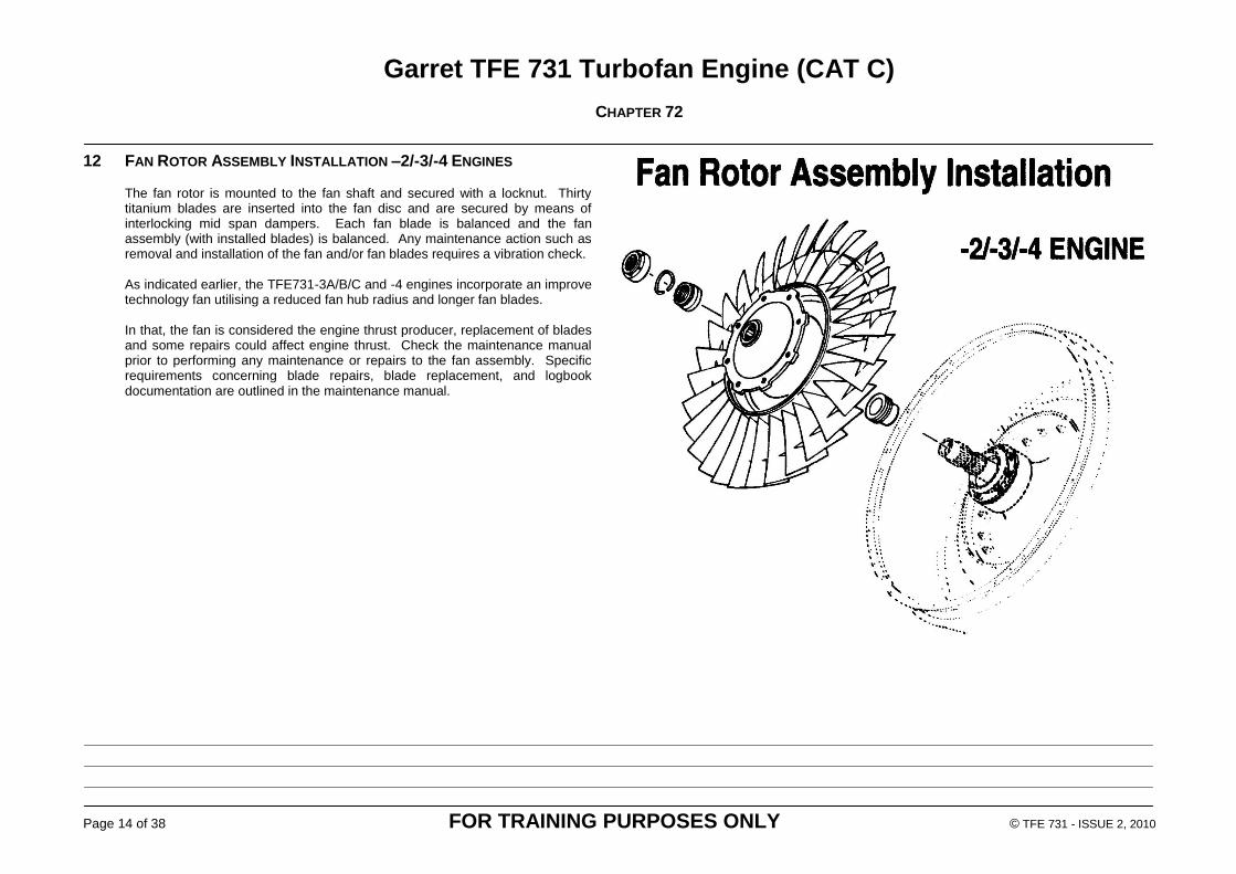
12 FAN ROTOR ASSEMBLY INSTALLATION –2/-3/-4 ENGINES The fan rotor is mounted to the fan shaft and secured with a locknut. Thirty titanium blades are inserted into the fan disc and are secured by means of interlocking mid span dampers. Each fan blade is balanced and the fan assembly (with installed blades) is balanced. Any maintenance action such as removal and installation of the fan and/or fan blades requires a vibration check. As indicated earlier, the TFE731-3A/B/C and -4 engines incorporate an improve technology fan utilising a reduced fan hub radius and longer fan blades. In that, the fan is considered the engine thrust producer, replacement of blades and some repairs could affect engine thrust. Check the maintenance manual prior to performing any maintenance or repairs to the fan assembly. Specific requirements concerning blade repairs, blade replacement, and logbook documentation are outlined in the maintenance manual.

Garret TFE 731 Turbofan Engine (CAT C)
CHAPTER 72
Page 15 of 38 FOR TRAINING PURPOSES ONLY © TFE 731 - ISSUE 2, 2010
13 FAN ROTOR ASSEMBLY INSTALLATION –5
ENGINE The TFE731-5 engine fan, while similar to the Dash 3 engine, is larger in diameter with redesigned blades and disc. The blade insertion method makes the blades appear to be loose and will rattle when hand turned. The longer, redesigned blade is a significant factor in the increased thrust production of the TFE731-5 engine.

Garret TFE 731 Turbofan Engine (CAT C)
CHAPTER 72
Page 16 of 38 FOR TRAINING PURPOSES ONLY © TFE 731 - ISSUE 2, 2010
14 FAN AREA
14.1 Description
The fan support assembly, inlet housing, bypass stator, and LP compressor stator are bolted to the engine support housing which is also the forward engine attach point. The fan support assembly houses the number one and number two bearings and the ring gear for the planetary gear assembly. A carbon face seal with rotor and an air labyrinth seal are installed forward of the number one bearing to prevent loss of oil into the fan air stream. The fan rotor is installed on the forward end of the fan support assembly. The fan inlet housing provides a sound-attenuated inlet duct that also incorporates a ring of armour plate for fan blade containment. Fan discharge air flows across the fan bypass stator and low pressure compressor stator. These stators direct airflow into the core and fan bypass duct, in addition to forming a compression stage. Sound-absorbent material is provided ahead and aft of the fan rotor tip as an integral part of the inlet housing.
Garret TFE 731 Turbofan Engine (CAT C)
CHAPTER 72
Page 17 of 38 FOR TRAINING PURPOSES ONLY © TFE 731 - ISSUE 2, 2010
15 FAN AREA
15.1 Engine installation differences
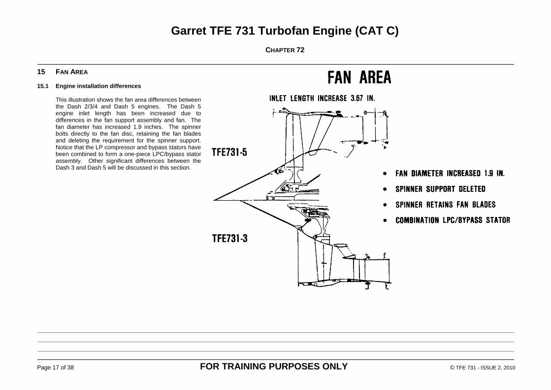
This illustration shows the fan area differences between the Dash 2/3/4 and Dash 5 engines. The Dash 5 engine inlet length has been increased due to differences in the fan support assembly and fan. The fan diameter has increased 1.9 inches. The spinner bolts directly to the fan disc, retaining the fan blades and deleting the requirement for the spinner support. Notice that the LP compressor and bypass stators have been combined to form a one-piece LPC/bypass stator assembly. Other significant differences between the Dash 3 and Dash 5 will be discussed in this section.

Garret TFE 731 Turbofan Engine (CAT C)
CHAPTER 72
Page 18 of 38 FOR TRAINING PURPOSES ONLY © TFE 731 - ISSUE 2, 2010
16 PLANETARY GEAR ASSEMBLY Power to drive the fan is provided by the planetary gear assembly. The high speed of the LP spool (N1) is transferred to torque by means of reduction gears referred to as the planetary gear assembly. The high speed pinion gear (commonly called sun gear) attached to the forward end of the low pressure compressor shaft drives five planetary gears. The planetary gears reduce input speed and turn the ring gear, which in turn drives the fan shaft. This gear arrangement changes fan rotation to counter clockwise rotation. The fan speed reduction by engine series is shown in the table. Each of the planetary gears is supported by two sets of roller bearings. Cooling and lubrication of these high speed gears and bearings is critical, since operating speeds of 53,788 RPM are reached at 100% RPM. The thrust loads and high speeds experienced in the planetary gear assembly require that oil entering this area is temperature and pressure controlled. This is an example of the speeds at 100% RPM:
Gearbox
Ratio Sun Gear
Ring Gear RPM
Planet RPM
-2/-3 0.555 20, 688 11,481 53,788
-4 0.555 21, 000 11,655 54,600
-5/5A 0.496 21, 000 10,416 41,349
-5B 0 .508 21, 000 10, 667 43,365

Garret TFE 731 Turbofan Engine (CAT C)
CHAPTER 72
Page 19 of 38 FOR TRAINING PURPOSES ONLY © TFE 731 - ISSUE 2, 2010
17 COMPRESSOR ZONE The four stage axial flow low pressure compressor is housed within the LP case assembly and is supported at the front by the number 3 bearing. This bearing absorbs the thrust loads of the LP compressor. The compressor is comprised of four rotating compressor discs (rotors) and four non-rotating stator rings. A shroud surrounds each compressor rotor. Each stator ring contains vanes that form a divergent duct allowing air pressure to increase and serve to direct airflow at the optimum angle to the succeeding wheel. As airflow progresses through the four stages of compression, each stage becomes smaller, causing a further increase in pressure. The compressor shrouds and wheels are coated with an aluminium abradable material. The blade tips machine the material as the wheel turns. This machining action between the stator rings and shrouds establishes an air seal that forces the air to flow through the compressor.

Garret TFE 731 Turbofan Engine (CAT C)
CHAPTER 72
Page 20 of 38 FOR TRAINING PURPOSES ONLY © TFE 731 - ISSUE 2, 2010
18 HIGH PRESSURE GROUP Mounted to the back of the LP case is the HP diffuser case. The high pressure compressor shaft and supporting bearings, accessory gearbox tower shaft, high pressure compressor impeller and shroud are contained within the HP diffuser case. Notice the gear on the left of this illustration. The HP shaft by means of a tower shaft drives the accessory gearbox. The tower shaft (not shown) extends through the HP diffuser case at the 6 o'clock position. A more detailed discussion of the gearbox and drive appears later in this section. The combustion plenum is mounted to the HP diffuser case and houses the diffuser, the deswirl and other combustion section components.

Garret TFE 731 Turbofan Engine (CAT C)
CHAPTER 72
Page 21 of 38 FOR TRAINING PURPOSES ONLY © TFE 731 - ISSUE 2, 2010
19 COMBUSTION SECTION High pressure bleed air is extracted from the engine at the combustor plenum. Notice also that two drain valves are located at the lowest part of the plenum. These valves are used to drain fuel from the plenum on engine shutdown. High pressure air exiting the diffuser flows through the deswirl where the air is stabilised prior to entering the combustor. The combustor is a stacked ring reverse flow annular type. A ceramic thermal barrier coating (TBC) is applied to the combustor skirts (inner surface of combustor) and to the outer transition liner. This ceramic coating, as its name implies, forms a thermal barrier for added protection of the combustor and transition liner. Provisions are also made for mounting fuel nozzles and igniters in the combustor.

Garret TFE 731 Turbofan Engine (CAT C)
CHAPTER 72
Page 22 of 38 FOR TRAINING PURPOSES ONLY © TFE 731 - ISSUE 2, 2010
20 COMBUSTION AND TURBINE SECTION During engine operation, high pressure compressor discharge air from the diffuser enters the deswirl, shown at the upper left of this illustration, and into the reverse flow combustor. Exiting combustor gases are turned by the transition liners and enter the high pressure nozzle (commonly referred to as A-4 nozzle) where the convergence increases the gas velocity and directs the gases to drive the high pressure turbine and the three stage low pressure turbine. Notice that a temperature probe is inserted into the interstage duct between the high pressure and low pressure turbines. The interstage transition duct shown in the upper right of this illustration bolts to the turbine plenum houses the low pressure turbine and provides a mounting boss for the ITT probes. The aft engine mounts are an integral part of the interstage transition duct. Also housed within the duct is the first stage LP turbine nozzle. Referred to as the A-5 nozzle, this nozzle is an integral part of the duct on Dash 2 engines, however is removable on all other engines. The A-5 nozzle assembly is air cooled on -2 series engines. Nozzle effective area (AE) can be changed to optimise engine performance.

Garret TFE 731 Turbofan Engine (CAT C)
CHAPTER 72
Page 23 of 38 FOR TRAINING PURPOSES ONLY © TFE 731 - ISSUE 2, 2010
21 HIGH PRESSURE TURBINE The high pressure turbine is comprised of a segmented high pressure turbine nozzle (A-4), a seal plate, the HPT rotor assembly, and associated couplings and nut used to secure the components to the high pressure shaft. The A-4 nozzle is made up of replaceable air-cooled segments that can be changed individually to optimise engine performance. High pressure compressor discharge air enters the nozzle assembly at the outer vane platform and circulates through the vane, exiting at the trailing edge, providing significant cooling. The TFE731-2 engine nozzle incorporates 14 segments while all other engine models utilise an 18 segment nozzle assembly. Four HP turbine rotor types are utilised in the 731 range engines. While all are installed in the same manner and feature air cooled discs, significant differences exist in blade designs and materials. These differences were brought about by efforts to improve engine performance and maintainability. The Dash 2 engines utilise a design with 78 solid blades riveted to the disc. The Dash 3 engines have 62 that are inserted into the disc and air-cooled on all but some -3B engines. Cooling air enters at the blade root and is discharged at the blade tip. TFE731-3B engines utilise improved blade materials and can be either air-cooled or non-air-cooled depending on service bulletin compliance. A manufacturing process called directionally solidification is used which improves the blade characteristics. Air-cooled directionally solidified blades (62) are used in the Dash 4 and Dash 5 engines. The purpose of the seal plate shown is to retain the blades in the disc and to direct cooling air to the face of the disc. Dash 2 engines utilise a seal rotor since blade retention is achieved with riveted blades. The couplings are used to secure the high pressure turbine components together and to the shaft.
These couplings provide a permanent coupling mechanism and allow component inter-changeability.

Garret TFE 731 Turbofan Engine (CAT C)
CHAPTER 72
Page 24 of 38 FOR TRAINING PURPOSES ONLY © TFE 731 - ISSUE 2, 2010
22 LOW PRESSURE (LP) TURBINE MODULE The three-stage low pressure turbine is removable from the engine in modular form. The LP turbine module consists of three turbine rotors and two nozzle assemblies held together with a stretched shaft. As indicated earlier, the first stage LPT nozzle (A-5) is integral with the interstage transition duct. Dash 2 and Dash 3 engines share a common turbine module that has an 86 blade first stage, 84 blade second stage, and an 80 blade third stage rotor. The blades are secured with rivets and the discs are air cooled.

Garret TFE 731 Turbofan Engine (CAT C)
CHAPTER 72
Page 25 of 38 FOR TRAINING PURPOSES ONLY © TFE 731 - ISSUE 2, 2010
23 LOW PRESSURE TURBINE A comparison of the Dash 4/5 and Dash 2/3 LP turbines is shown here. TFE731-4/-5 engines incorporate a larger, more efficient low pressure turbine. Fewer blades are used in all three stages (1st stage 64, 2nd 52, and 3rd 56) and are secured to the disc with retainers. The first stage blades are directionally solidified and replaceable honeycomb seals are used throughout. Hot gas deflectors are incorporated in the turbine rotor blade roots. Called discouragers, these deflectors act to prevent hot gas recirculation within the turbine, thus improving turbine efficiency.

Garret TFE 731 Turbofan Engine (CAT C)
CHAPTER 72
Page 26 of 38 FOR TRAINING PURPOSES ONLY © TFE 731 - ISSUE 2, 2010
24 THRUST AND EXHAUST NOZZLE The thrust and exhaust nozzle is bolted to the interstage transition duct and houses the low pressure turbine exit vanes. The nozzle provides a mount for the aft LP turbine support bearing (#6) and houses and N1 speed sensor. Note the oil tubes for lubrication of the number 6 bearing. The thrust and exhaust nozzle for the Dash 4 and Dash 5B engines differs in that the rear bearing support is modified by eliminating two of the service tube locations and enclosing all service tubes in an aerodynamic fairing. The #6 bearing oil supply, scavenge and N1 monopole lead is routed through the 6 o'clock service strut. These changes reduce the pressure losses in the gas path resulting in improved thrust specific fuel consumption.

Garret TFE 731 Turbofan Engine (CAT C)
CHAPTER 72
Page 27 of 38 FOR TRAINING PURPOSES ONLY © TFE 731 - ISSUE 2, 2010
25 MIXER NOZZLE INSTALLATION A mixer nozzle is utilised on the TFE731-5A/5B engines. The nozzle is secured to the thrust and exhaust nozzle by means of a V-band clamp. The mixer nozzle forces the high speed exhaust from the turbine to combine with the low speed air from the fan with less shear between the moving streams, thus lowering noise. Thrust increase is achieved by this air mixing which transfers energy to the bypass air. Additional enhancements on the Dash 4 and 5B engines such as the aerodynamic single oil service strut combine to increase performance.
Garret TFE 731 Turbofan Engine (CAT C)
CHAPTER 72
Page 28 of 38 FOR TRAINING PURPOSES ONLY © TFE 731 - ISSUE 2, 2010
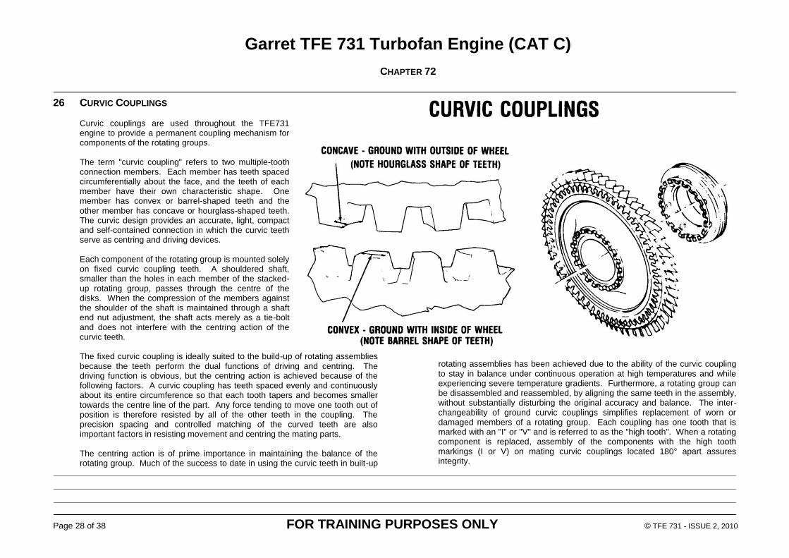
26 CURVIC COUPLINGS Curvic couplings are used throughout the TFE731 engine to provide a permanent coupling mechanism for components of the rotating groups. The term "curvic coupling" refers to two multiple-tooth connection members. Each member has teeth spaced circumferentially about the face, and the teeth of each member have their own characteristic shape. One member has convex or barrel-shaped teeth and the other member has concave or hourglass-shaped teeth. The curvic design provides an accurate, light, compact and self-contained connection in which the curvic teeth serve as centring and driving devices. Each component of the rotating group is mounted solely on fixed curvic coupling teeth. A shouldered shaft, smaller than the holes in each member of the stacked-up rotating group, passes through the centre of the disks. When the compression of the members against the shoulder of the shaft is maintained through a shaft end nut adjustment, the shaft acts merely as a tie-bolt and does not interfere with the centring action of the curvic teeth. The fixed curvic coupling is ideally suited to the build-up of rotating assemblies because the teeth perform the dual functions of driving and centring. The driving function is obvious, but the centring action is achieved because of the following factors. A curvic coupling has teeth spaced evenly and continuously about its entire circumference so that each tooth tapers and becomes smaller towards the centre line of the part. Any force tending to move one tooth out of position is therefore resisted by all of the other teeth in the coupling. The precision spacing and controlled matching of the curved teeth are also important factors in resisting movement and centring the mating parts. The centring action is of prime importance in maintaining the balance of the rotating group. Much of the success to date in using the curvic teeth in built-up
rotating assemblies has been achieved due to the ability of the curvic coupling to stay in balance under continuous operation at high temperatures and while experiencing severe temperature gradients. Furthermore, a rotating group can be disassembled and reassembled, by aligning the same teeth in the assembly, without substantially disturbing the original accuracy and balance. The inter-changeability of ground curvic couplings simplifies replacement of worn or damaged members of a rotating group. Each coupling has one tooth that is marked with an "I" or "V" and is referred to as the "high tooth". When a rotating component is replaced, assembly of the components with the high tooth markings (I or V) on mating curvic couplings located 180° apart assures integrity.

Garret TFE 731 Turbofan Engine (CAT C)
CHAPTER 72
Page 29 of 38 FOR TRAINING PURPOSES ONLY © TFE 731 - ISSUE 2, 2010
27 MAIN ENGINE BEARINGS Thirty four precision high speed bearings are used in the engine. The bearings fall into two general types, that being separable and non-separable ball and roller type. Of these, six are considered main engine bearings used to support the two rotating groups and the fan. The main engine bearings inner races are press-fitted onto the shafts and outer bearing races are hydraulic mounted with the exception of number 2 bearing that is mechanically mounted. The hydraulic mount provides a film of oil around the outer race of the bearing to absorb shock and to keep the bearing centred. Each of the two spools and the fan shaft is mounted on a ball and roller bearing. The ball bearing accepts thrust loads and the roller bearing absorbs shaft radial loads. The fan is supported by the numbers 1 (roller) and 2 (ball) bearings. The low pressure spool is supported by the numbers 3 (ball) and 6 (roller) bearings while numbers 4 (roller) and 5 (ball) bearings support the HP spool. Eleven bearings are used in the planetary gearbox, seven in the tower shaft and transfer gearbox and ten ball bearings are installed in the accessory gearbox. These bearings will be discussed later in this section.

Garret TFE 731 Turbofan Engine (CAT C)
CHAPTER 72
Page 30 of 38 FOR TRAINING PURPOSES ONLY © TFE 731 - ISSUE 2, 2010
28 LABYRINTH SEALS Seals are used throughout the engine to control and regulate airflow. In the compressor and turbine areas, the seals are used to control airflow and balance leakage pressures between stages. Seals are also used in the bearing sumps to regulate air pressures at the carbon seals. That type seal will be addressed in the lubrication section of this study guide. The labyrinth seal is comprised of a series of knife-edges that cut into an abradable surface to create a labyrinth that controls airflow and pressures. Most applications utilise two or more knife-edges attached to a rotating component that cut into a stationary abradable material. A stepped configuration is used on some models. The abradable is a sprayed-on material that, as its name applies, wears away. A carbon material is used in turbine areas, while aluminium abradable is used in the LP compressor. Later engine models utilise a stainless steel honeycomb material providing improved sealing and increased life. The arrows on this illustration indicate typical high pressure compressor discharge cooling airflow through the turbine area.

Garret TFE 731 Turbofan Engine (CAT C)
CHAPTER 72
Page 31 of 38 FOR TRAINING PURPOSES ONLY © TFE 731 - ISSUE 2, 2010
29 AIRFLOW STATIONS Station numbers are assigned to areas of the engine and for the most part identify a significant point in the gas path. These points are generally used when referring to areas of the engine in a sort of shorthand. For example, station one identifies the area immediately in front of the engine and is normally used when referring to ambient conditions. At station 2, immediately forward of the fan, the air velocity resulting from the forward motion of the aircraft has been converted to pressure by the aircraft inlet plenum. The pressure and temperature of the air is sensed at this point and is used by the engine electronic control (EEC) to set engine operation. The low pressure compressor discharge is identified as station 2.35, while high compressor discharge is generally referred to as P3, or pressure at station 3. Pressure at station 3 is the highest pressure within the engine. Comparisons of pressures at station 2.35 and station 3 can highlight compressor performance. Station 5 identifies an area of the interstage transition duct between the HP turbine outlet and the LP turbine inlet. This interstage area is where the turbine temperature is measured. The thrust and exhaust nozzle is referenced as station 7.

Garret TFE 731 Turbofan Engine (CAT C)
CHAPTER 72
Page 32 of 38 FOR TRAINING PURPOSES ONLY © TFE 731 - ISSUE 2, 2010
30 GEARBOX MODULE The gearbox module is located at the bottom forward end of the engine and consists of a transfer gearbox and an accessory gearbox. The N2 spool through the tower shaft drives the transfer gearbox. A bevel gear mounted to the N2 shaft drives the tower shaft and the rotary motion is transferred through a horizontal shaft to drive the accessory gearbox. The transfer gearbox provides 2.5 to 1 speed reduction. The N2 speed sensor (monopole) is housed within the transfer gearbox. The accessory gearbox provides drives and mounting pads on the forward side of the gearbox for customer-furnished accessories such as starters, generators, and pumps. The engine fuel pump and control, oil pump and accessories are located on the aft side of the gearbox. The accessory gearbox drive splines must be lubricated prior to installation of accessories to prevent excessive spline wear. Periodic inspection of the splines is required. Check your specific engine manual for inspection procedures and frequency. Replaceable spline adapters are available to prevent wear to the drive splines. The adapters require a modification of the drives, which can be accomplished through service bulletin compliance. The Dash 5 accessory gearbox is mounted slightly lower to accommodate the increased fan diameter. A side-loaded support strut has been added and upgraded support bearings.
This concludes our introductory examination of engine theory and the construction concepts of the engine. The discussion of the different engine types would be incomplete, however, without an in-depth review of the engine thrust ratings, and the thrust limitations.

Garret TFE 731 Turbofan Engine (CAT C)
CHAPTER 72
Page 33 of 38 FOR TRAINING PURPOSES ONLY © TFE 731 - ISSUE 2, 2010
Garret TFE 731 Turbofan Engine (CAT C)
CHAPTER 72
Page 34 of 38 FOR TRAINING PURPOSES ONLY © TFE 731 - ISSUE 2, 2010

Garret TFE 731 Turbofan Engine (CAT C)
CHAPTER 72
Page 35 of 38 FOR TRAINING PURPOSES ONLY © TFE 731 - ISSUE 2, 2010
Garret TFE 731 Turbofan Engine (CAT C)
CHAPTER 72
Page 36 of 38 FOR TRAINING PURPOSES ONLY © TFE 731 - ISSUE 2, 2010

Garret TFE 731 Turbofan Engine (CAT C)
CHAPTER 72
Page 37 of 38 FOR TRAINING PURPOSES ONLY © TFE 731 - ISSUE 2, 2010

Garret TFE 731 Turbofan Engine (CAT C)
CHAPTER 72
Page 38 of 38 FOR TRAINING PURPOSES ONLY © TFE 731 - ISSUE 2, 2010
PAGE INTENTIONALLY LEFT BLANK