TFC-ENG-STD-12, Tank Farm Equipment Identification ...
55
Tank Farm Equipment Identification Numbering and Labeling Standard Manual Document Page Issue Date Engineering TFC-ENG-STD-12, REV E-6 1 of 55 August 12, 2021 Ownership Matrix RPP-27195 TABLE OF CONTENTS 1.0 PURPOSE AND SCOPE ................................................................................................................. 3 2.0 IMPLEMENTATION ...................................................................................................................... 5 3.0 STANDARD .................................................................................................................................... 5 3.1 General Requirements......................................................................................................... 6 3.1.1 Human Performance Improvement Considerations ............................................... 6 3.2 Equipment Identification Number Structure ....................................................................... 7 3.2.1 General Equipment Identification Number Convention ........................................ 7 3.2.2 Waste Transfer Line Equipment Identification Numbering ................................ 12 3.2.3 Jumpers Equipment Identification Numbering .................................................... 17 3.2.4 Other Transfer System Elements Equipment Identification Numbering Convention .................................................................................................... 22 3.2.5 Ground Fault Circuit Interrupter .......................................................................... 31 3.2.6 Ground Fault Equipment Protection .................................................................... 32 3.3 Labeling Requirements ..................................................................................................... 33 3.3.1 General Labeling Requirements .......................................................................... 33 3.3.2 Label Sizing .................................................................................................... 36 3.3.3 Label Format .................................................................................................... 36 3.3.4 Attaching Labels .................................................................................................. 37 3.3.5 Label Placement ................................................................................................... 37 3.3.6 Label Verification ................................................................................................ 38 3.3.7 Temporary Labels ................................................................................................ 38 3.3.8 Electrical Equipment............................................................................................ 38 3.3.9 Motor Control Centers ......................................................................................... 39 4.0 DEFINITIONS............................................................................................................................... 39 5.0 SOURCES ..................................................................................................................................... 40 5.1 Requirements .................................................................................................................... 40 5.1.1 ANSI/ASME A13.1, “Pipe Labeling to ANSI-ASME A13.1.”........................... 40 5.1.2 DOE O 422.1, “Conduct of Operations.” ............................................................ 40 5.1.3 RPP-14541, “Jumper Fabrication and Testing Specification for Tank Farms.” .. 40 5.1.4 TFC-ENG-FACSUP-C-23, “Equipment Identification and Data Management.” 40 5.1.5 TFC-PLN-05, “Conduct of Operations Implementation Plan.” ........................... 40 5.1.6 ANSI/ISA 5.1 (2009), “Instrumentation Symbols and Identification.” ............... 40 5.2 References......................................................................................................................... 40 5.2.1 ASME Y14.38, “Tank Farm Safety Instrumented Code of Record, Abbreviations and Acronyms for Use on Drawings and Related Documents.” .......................... 40
Transcript of TFC-ENG-STD-12, Tank Farm Equipment Identification ...

Tank Farm Equipment Identification Numbering and Labeling Standard
Manual Document Page Issue Date
Engineering TFC-ENG-STD-12, REV E-6
1 of 55 August 12, 2021
Ownership Matrix
RPP-27195
TABLE OF CONTENTS 1.0 PURPOSE AND SCOPE ................................................................................................................. 3 2.0 IMPLEMENTATION ...................................................................................................................... 5 3.0 STANDARD .................................................................................................................................... 5
3.1 General Requirements ......................................................................................................... 6 3.1.1 Human Performance Improvement Considerations ............................................... 6
3.2 Equipment Identification Number Structure ....................................................................... 7 3.2.1 General Equipment Identification Number Convention ........................................ 7
3.2.2 Waste Transfer Line Equipment Identification Numbering ................................ 12
3.2.3 Jumpers Equipment Identification Numbering .................................................... 17
3.2.4 Other Transfer System Elements Equipment Identification Numbering Convention .................................................................................................... 22
3.2.5 Ground Fault Circuit Interrupter .......................................................................... 31
3.2.6 Ground Fault Equipment Protection .................................................................... 32
3.3 Labeling Requirements ..................................................................................................... 33 3.3.1 General Labeling Requirements .......................................................................... 33
3.3.2 Label Sizing .................................................................................................... 36
3.3.3 Label Format .................................................................................................... 36
3.3.4 Attaching Labels .................................................................................................. 37
3.3.5 Label Placement ................................................................................................... 37
3.3.6 Label Verification ................................................................................................ 38
3.3.7 Temporary Labels ................................................................................................ 38
3.3.8 Electrical Equipment ............................................................................................ 38
3.3.9 Motor Control Centers ......................................................................................... 39
4.0 DEFINITIONS ............................................................................................................................... 39 5.0 SOURCES ..................................................................................................................................... 40
5.1 Requirements .................................................................................................................... 40 5.1.1 ANSI/ASME A13.1, “Pipe Labeling to ANSI-ASME A13.1.” ........................... 40
5.1.2 DOE O 422.1, “Conduct of Operations.” ............................................................ 40
5.1.3 RPP-14541, “Jumper Fabrication and Testing Specification for Tank Farms.” .. 40
5.1.4 TFC-ENG-FACSUP-C-23, “Equipment Identification and Data Management.” 40
5.1.5 TFC-PLN-05, “Conduct of Operations Implementation Plan.” ........................... 40
5.1.6 ANSI/ISA 5.1 (2009), “Instrumentation Symbols and Identification.” ............... 40
5.2 References ......................................................................................................................... 40 5.2.1 ASME Y14.38, “Tank Farm Safety Instrumented Code of Record, Abbreviations
and Acronyms for Use on Drawings and Related Documents.” .......................... 40

Tank Farm Equipment Identification Numbering and Labeling Standard
Manual Document Page Issue Date
Engineering TFC-ENG-STD-12, REV E-6
2 of 55 August 12, 2021
5.2.2 IEEE, “Standard Dictionary of Electrical and Electronics Terms.” .................... 40
5.2.3 TFC-ENG-DESIGN-C-56, “Modification Traveler.” ......................................... 40
5.2.4 TFC-ENG-DESIGN-D-51, “ECN Preparation and Work Completion Walkdown.” .................................................................................................... 40
5.2.5 TFC-ENG-DESIGN-P-17, “Design Verification.” .............................................. 40
5.2.6 TFC-OPS-OPER-C-32, “Farm Temporary Component Identification Tags.” .... 40
TABLE OF FIGURES Figure 1 - NF Label Coding ........................................................................................................................ 41 Figure 2 - NH Label Coding ....................................................................................................................... 42 Figure 3 - NL Label Coding ........................................................................................................................ 43 Figure 4 - NK Label Coding ....................................................................................................................... 44 Figure 5 - NE Label Coding ........................................................................................................................ 45 Figure 6 - NM Label Coding ...................................................................................................................... 46 Figure 7 - Label (13) Coding ...................................................................................................................... 47 Figure 8 - Label (NJ) Coding ...................................................................................................................... 48 Figure 9 - Control Panel Labels .................................................................................................................. 49
TABLE OF ATTACHMENTS Attachment A - Approved Deviations ........................................................................................................ 50

Tank Farm Equipment Identification Numbering and Labeling Standard
Manual Document Page Issue Date
Engineering TFC-ENG-STD-12, REV E-6
3 of 55 August 12, 2021
1.0 PURPOSE AND SCOPE
TFC-PLN-05 outlines the implementation of the Conduct of Operations Program, which includes the requirements for a labeling program to be established and maintained to help ensure facility personnel are able to positively identify equipment they operate. This standard ensures equipment abbreviations and descriptions provided by Equipment Identification Numbers (EINs) and shown on labels is established and easily understood by facility personnel. In addition, it provides a means for drawings, procedures, round sheets, and piping and instrument diagrams (P&IDs) to show consistent EINs and labels for the same piece of equipment installed in the field. See Section 3.3.7 for label verification. (5.1.5)
This standard is applicable to labels applied to equipment in Washington River Protection Solutions, LLC (WRPS) operating facilities. This standard does not mandate application of labels to equipment in administrative, support, or other peripheral facilities, systems, or structures. If it is determined necessary to apply labels to equipment in administrative, support, or other non-process-related peripheral facilities, systems, or structures, those labels shall follow this standard (with the exceptions listed below and in Table A-2). Hanford-installed modifications, or vendor equipment used to support WRPS operations (manipulated by procedure or work instruction), or hazardous energy control isolation shall be identified either by a uniquely-identified existing permanent label or a WRPS-installed temporary label, in accordance with TFC-OPS-OPER-C-32. Systems and components owned and maintained by Hanford Mission Integration Solutions (HMIS) are exempt from this standard. These include utilities outside a facility, such as electrical power lines, feeding a facility, or water utilities supplying a facility. Fire protection components maintained by HMIS, inside and outside, facilities, are also exempt from this standard. New EINs for equipment and piping installed across all WRPS facilities (Tank Farms, 242-A Evaporator, Effluent Treatment Facility [ETF], Treated Effluent Disposal Facility [TEDF], and Liquid Effluent Retention Facility [LERF]) shall be obtained from SmartPlant®1 Foundation (SPF). SPF contains standardized formats for EINs (in accordance with this standard) and uses standardized location designators, system acronyms, component type acronyms, and automated sequence numbering. Additional information on creating EINs, EIN labels, and the information to be provided for new equipment is provided in TFC-ENG-FACSUP-C-23. (5.1.4) Many EINs were created prior to this standard and prior to the implementation of SPF in October 2014. These EINs may have been created to different format requirements than those specified in this standard. There is no expectation in this standard that EINs created prior to SPF or prior to this standard be renumbered or re-labeled to match the format of this standard. Requests for deviation to any of the numbering or labeling requirements of this standard shall be requested from the Standard Owner. Deviations to the requirements of the standard are not desirable but will be considered on their merits. Approved deviations are documented in Tables A-1 and A-2 of this standard. These tables will be periodically updated to reflect newly agreed deviations. New deviations may be used once agreed by the Standard Owner prior to incorporation into this standard. The following procedures and legend drawings have historically been used to number and label equipment at 242-A Evaporator, ETF, LERF, and TEDF. Location identifiers, systems, and component acronyms from these sources have been incorporated into SPF and standardized
1 SmartPlant® Foundation is a registered trademark of Hexagon of Madison, Alabama.

Tank Farm Equipment Identification Numbering and Labeling Standard
Manual Document Page Issue Date
Engineering TFC-ENG-STD-12, REV E-6
4 of 55 August 12, 2021
where appropriate. Reference to these procedures and standards should not normally be required for creating new EINs. New EINs within these facilities shall be obtained from SPF as previously stated, except as indicated in Section 3.1.1. NOTE: These drawings are no longer in use. They are provided here for historical information only. No DCNs/ECNs shall be written against these drawings to add any new location identifiers, component identifiers, or system identifiers. These items are now managed in SPF. Any changes to the drawings below require prior approval of the Engineering Programs Manager.
EINs and labeling of equipment and piping installed in the 242-A Evaporator were
originally developed in accordance with drawing H-2-98986, Sheet 1.
EINs and labeling of equipment and piping installed in the ETF were originally developed in accordance with drawing H-2-89351-1, “Piping & Instrument Diagram – Legend.”
EINs and labeling of equipment and piping installed in the TEDF were originally
developed in accordance with drawing H-2-79601-1, “P&ID 242-A Evap Legend” and H-2-815119-1, “P&ID Disposal Station Symbols and Legends.”
EINs and labeling of equipment and piping installed in the LERF were originally
developed in accordance with drawing H-2-79601-1, “P & ID 242-A Evap Legend” and H-2-827217-1, “Piping P&ID Groundwater Transfer, Head-End.”
EINs and labeling of consumables (e.g., Safety-Significant Drum Vents) are exempt from this standard. Specific guidelines are provided for EINs and labels, including specifications, formats, and materials for labels used in TOC facilities. In addition to equipment, doors to rooms shall be labeled so that personnel can identify the room and, if applicable, the equipment inside. (5.1.2, 5.1.5)
The following components shall be labeled: (5.1.2, 5.1.5)
Above ground piping
Valves and dampers
Equipment (e.g., tanks, pumps, motors and compressors)
Switches
Circuit breakers (4.16KV, 480V, 120VAC/DC, etc.)
Fuse blocks or fuse locations
Instruments and gauges
Busses and motor control centers
Cabinets (including internal components such as relays, terminals, etc.)

Tank Farm Equipment Identification Numbering and Labeling Standard
Manual Document Page Issue Date
Engineering TFC-ENG-STD-12, REV E-6
5 of 55 August 12, 2021
Room doors
Emergency equipment (such as fire alarm stations, sound powered phone headsets, etc.), except components owned and maintained by HMIS
Fire protection systems – except components owned and maintained by HMIS
Any named safety structures, systems, and components (SSC) item or operator control
Ventilation duct.
2.0 IMPLEMENTATION
This standard is effective on the date shown in the header. New EINs for equipment and piping installed across all WRPS facilities (Tank Farms, 242-A Evaporator, ETF, TEDF, and LERF) shall be obtained from SPF. This standard clarifies this requirement for Tank Farms, and 242-A Evaporator and implements the requirement for ETF, LERF, and TEDF. EINs created prior to the implementation of SPF or prior to implementation of this standard may have been created to different format requirements than those specified in this standard. There is no expectation in this standard that EINs created prior to SPF or prior to this standard be renumbered or re-labeled to match the format of this standard. Requests for deviation to any of the numbering or labeling requirements of this standard shall be requested from the Standard Owner, except as allowed under Section 3.1.1. All Safety-Significant Waste Transfer Primary Piping Elements installed after the issue date of revision C of this standard must be labeled unless specifically exempted in Attachment A. Primary piping equipment in storage shall be labeled as required prior to installation. Prior to this revision, the use of backslashes embedded in the EIN was mandatory for instruments that performed more than two functions all in one device. According to ANSI/ISA 5.1 (2009), instruments that perform more than two functions should not include backslashes in the component field. Rather, the basic function shall be used, e.g., SIS. The EIN would be POR346-WT-SIS-102, with the other functions depicted in the description. The Equipment Title would be SPEED INDICATOR SWITCH/HIGH/HIGH-HIGH. (5.1.6)
Existing EINs created prior to this revision, with backslashes embedded in the EIN, are exempt from this change.
3.0 STANDARD
Approved deviations from the requirements of this standard are identified in Attachment A.

Tank Farm Equipment Identification Numbering and Labeling Standard
Manual Document Page Issue Date
Engineering TFC-ENG-STD-12, REV E-6
6 of 55 August 12, 2021
3.1 General Requirements
1. EINs are established in SPF per TFC-ENG-FACSUP-C-23, and associated SPF-TAGi form instructions. (5.1.4)
2. Application of EINs or labels that are inconsistent with this standard, unless addressed by
approved deviations, are prohibited. Approved deviations for Labeling and EIN identification on drawings are listed in Table A-2 of Attachment A.
3. Onsite fabricated labels should be permanent, securely attached, and have
distinguishable, easy-to-read information. A description of power supply information should also be provided, where applicable.
4. Accessible/visible above grade piping shall have marking to indicate the fluid contained
and the normal flow direction. OSHA/ANSI A13.1 color coding for piping should be used, and pipes containing potentially radioactive, toxic, or explosive chemicals or gases may be uniquely marked and legible at a distance of at least 50 feet. (5.1.1)
5. For vessels and tanks located in pits or vaults, clearly visible dangerous waste warning
labels shall be located at all above grade and below grade access points to the associated pit or vault and shall be clearly legible from six feet away.
6. An abbreviated EIN consisting of the component acronym and sequence number may be
used for labeling of vessels, tanks, and equipment located in pits. The abbreviated EIN may be painted and stenciled to allow viewing from above. Letters and numbers shall be 2” to 6” in height, block type lettering. A lettering stencil, 1” or greater, may be used for component identification where a flat surface cannot accommodate a 2” stencil.
7. Jumper identification and labeling shall follow RPP-14541 (Jumper Fabrication and
Testing for Tank Farms). (5.1.3)
3.1.1 Human Performance Improvement Considerations
1. All equipment numbering at Tank Farms shall follow this standard.
2. As discussed in Section 1.0, equipment numbers for 242-A, and ETF, LERF, TEDF were originally assigned using different numbering schemes than identified in this standard.
a. Equipment added as part of a significant modification shall follow the numbering
scheme(s) in this standard (e.g., replaces or adds a large number of components, such as installing replacement ventilation system or new chiller system).
b. Equipment added as a minor modification may use the original facility
numbering scheme, if desired by operations for HPI purposes (e.g., addition of a new valve adjacent to several valves numbered to the original scheme).

Tank Farm Equipment Identification Numbering and Labeling Standard
Manual Document Page Issue Date
Engineering TFC-ENG-STD-12, REV E-6
7 of 55 August 12, 2021
3. Manual selection of sequence numbers may be made in SPF using the “Start at number” field. This method may be used to avoid the same sequence number being used on say valves on different systems in close proximity to each other. The method may also be used to allow the same components on equivalent portable ventilation skids to carry the same sequence number.
3.2 Equipment Identification Number Structure
The following are the conventions for numbering equipment, where the General EIN Number convention as described in Section 3.2.1 applies to all types of equipment unless described specifically in the following sections or where specifically exempted as listed in Attachment A. The following list shows those items that have specific naming conventions that are different from the general convention.
Section # EIN Numbering Convention
3.2.2 Waste Transfer Line Buried Waste Transfer Line Hose-In-Hose
3.2.3 Jumper Rigid Jumper Flexible-Metal Hose EPDM Hose
3.2.4 Other Transfer System Elements Hose-In-Hose Adapters PUREX Type Process Blank Chem Connector Process Blank Tank Return (Numbered Inlet Riser) Tank Return Equipment Mounted in a Riser Other Miscellaneous Equipment
3.2.1 General Equipment Identification Number Convention
The Standard EIN is comprised of four fields, described below. These fields are derived from standard fields in SPF. EINs are limited to a maximum of 30 characters, which is dictated by the work control system, EAM.
Specific EIN conventions related to Safety-Significant Primary Piping are described in the following sections.

Tank Farm Equipment Identification Numbering and Labeling Standard
Manual Document Page Issue Date
Engineering TFC-ENG-STD-12, REV E-6
8 of 55 August 12, 2021
AN101-VTP-FIT-002ASEQUENCEBUILDING /FACILITY PRIMARY
SYSTEM COMPONENT TYPE
SPF FIELD NAME
FIELD DESCRIPTION SPF IMPLEMENTATION
PRIMARY BUILDING/ FACILITY
Designates Building/Facility where equipment or component is located and building, tank, pit, or other structure the equipment or component is located in, on, or near. Items not directly related to a specific structure location are identified by the general area where they are located (241, 244, 151, etc.).
These fields are completed by identifying the “Primary Building/Facility” in SPF. For all WRPS controlled facilities and locations in SPF, SPF includes a location designator specific to that facility/location e.g., selecting 241-AN-101 as the “Primary Building/Facility” in SPF will assign AN101 as the farm/location identifier.
PRIMARY SYSTEM
Designates primary system type with which equipment or component is associated.
This field is completed by identifying the “Primary System” in SPF. For each system in SPF (broken down by facility), SPF contains a system acronym e.g., for Tank Farms, selecting a “Primary System” of 241-VTP (Ventilation Tank, Primary), will assign a system designator of VTP.
COMPONENT TYPE
Describes equipment or component type.
In SPF, selection of the component type is the starting point for EIN creation. From the Tag Type tree in SPF, selecting a tag type of INSTRUMENTATION>F, FLOW INSTRUMENTATION>FIT, FLOW INDICATING TRANSMITTER will assign the appropriate acronym for the type of equipment, in this example FIT for a flow indicating transmitter.
SEQUENCE NUMBER
Unique sequence designator (e.g., 123A) for a particular equipment or component. The first three characters (required) are always numbers; the fourth, if used, must be an alpha character.
In SPF the sequence number is automatically assigned, although the “Start at number” field may be used to specify a specific 3-digit sequence number if desired. The “ENS Sequence Suffix” field in SPF may be used to specify an alpha character suffix for designating duty and standby components e.g., 001A or 001B.
Deviations to the EIN numbering convention are shown in Table A-1 in Attachment A.

Tank Farm Equipment Identification Numbering and Labeling Standard
Manual Document Page Issue Date
Engineering TFC-ENG-STD-12, REV E-6
9 of 55 August 12, 2021
1. The following rules apply when assigning EIN SEQUENCE numbers:
a. With the exception of “redundant trains,” “instrument loop components,” and as noted below, the sequence number is considered random and provides uniqueness between two otherwise identical component EINs.
b. Sequence numbers range from 001 to 999. c. Sequence number assignment typically follows the process flow. Low numbers
are at the process beginning and high numbers are at the process end. Use the “Start at number” field in the bottom left corner of the initial EIN create screen, if specific sequence numbers are desired.
d. Embedded tank thermocouples may use the original temperature element
numbering coinciding with existing wire number coding.
e. Risers are considered a tank-related structure and may be labeled beginning with number 001. Sequence numbers repeat from system to system, tank to tank.
f. Redundant equipment trains shall have sequence numbering that clearly indicates
the different trains (e.g., Train A: AW241-VTP-V-110 and Train B: AW241-VTP-V-210.)
g. Like components with the same sequence number use alpha suffixes (for
example, in instrument loops: TI-110A, TI-110B, TI-110C, etc.) Use the “ENS Sequence Suffix” field on the initial EIN create screen.

Tank Farm Equipment Identification Numbering and Labeling Standard
Manual Document Page Issue Date
Engineering TFC-ENG-STD-12, REV E-6
10 of 55 August 12, 2021
Associated equipment (instrument loops and associated control valves) may receive the same sequence number. This sequence number cannot be used again for any other device in the same system for the same farm.
h. Alpha suffixes to be used for components that perform the same function shall be
labeled such that the components are sequenced as follows: begin first with local equipment, then control room equipment and lastly, remote equipment. Alpha suffixes are used to differentiate between like components within a single loop, but are NOT used to group like components from different loops.
EXAMPLE: A leak detector that has an alarm at the detector, in the control room and at the evaporator could have leak detection alarm (LDA) EINs with the following Component and Sequence descriptors:
LDA-101A at the detector LDA-101B in the control room LDA-101C in the evaporator building.
i. The electrical distribution system boundary is located at the final electrical
component (e.g., motor control center, disconnect switch, distribution panel, etc.) feeding another system’s auxiliary equipment (e.g., exhaust fan motor, pump motor, motor-operated valves, etc.). The portable ventilation skid equipment may be labeled as part of the VTP system. The electrical feeder to that skid will be part of the VTP system. Refer to the system design descriptions for a description of the system interface boundary.
j. Local disconnects shall have the same system designation and sequence number
as the equipment or component they power.
k. Auxiliary equipment (e.g., current transformers, meters, indicators, etc.) associated with a breaker either within, or associated with the cubicle, do not have an EIN because they are a subcomponent of the equipment.
l. Motors, which are by application considered separate from the driven equipment, are individually numbered using the same sequence number as the driven equipment.
m. Primary Location designators i.e., Primary Building/Facility help identify the location for a component. This includes all components installed inside the building or within close proximity to the building. In this case, the associated P&ID shall show the component with a border drawn around it or a reference note beside it to indicate the physical location of the component. This includes all components installed inside the building or within close proximity to the building that are located outside the building. When the component is not located in a specific tank farm, inside a building or within close proximity to a building they shall be labeled as 241G. In this case, the associated P&ID shall show the component with a border drawn around it or a reference note beside it to indicate the physical location of the component.
Small motor pump combinations (e.g., vacuum pumps) are identified by the pump EIN only.

Tank Farm Equipment Identification Numbering and Labeling Standard
Manual Document Page Issue Date
Engineering TFC-ENG-STD-12, REV E-6
11 of 55 August 12, 2021
Example: Component AY271-WT-WFA-140 supports the AY DST System and is labeled “AY271.” This component is physically located in 241-A271 Building. The associated AY P&ID shows this component with a border surrounding it, identifying it at the “A-271” location.
EXCEPTION: An exception to this rule exists at the 241-AZ building for equipment serving the AN and AY tank farms. See PER-2004-5809 and PER-2005-0058 for a complete description. There are no plans to change these EINs to meet the requirements of this standard. New equipment shall follow this standard.
n. Equipment or subcomponents that are labeled by the manufacturer may have the
manufacturer label in parenthesis after the assigned EIN.
Example: An enclosure, panel, or system that has a number of components contained within that have manufacturer provided labels, may have EINs as follows:
AN241-EDS-DP-130 AN241-EDS-DP-130(CB-1) AN241-EDS-DP-130(CB-2) AN241-EDS-DP-130(CB-3) AN101-WT-LDE-180 AN101-WT-LDE-180(LD1) AN101-WT-LDE-180(LD3).
2. Pushbuttons, Lights, Selector Switches, and Hand Switches.
a. If the associated panel is assigned an EIN/label and the vendor has labeled the
equipment adequately on the panel, no EIN or field label is required; otherwise, this standard applies.
3. Portable or mobile equipment (e.g., trailer or skid mounted compressors, generators, etc.)
that may be moved from farm to farm or other locations are assigned portable farm and location EIN codes as follows:
POR numbers are assigned by SPF Administration e.g., “POR##” identifies the
general category of a piece of Portable RPP equipment (where ## is a two or three-digit sequence number; e.g., POR25).
Remaining EIN fields are assigned in SPF like all other equipment.
4. Instruments that perform multiple functions, all in one device, shall use the component
type in SPF for the basic function of the device. For instance, a Speed Indicator would use SI, while a Speed Indicator Switch High would use SISH, and Speed Indicator Switch High-Low would use SISHL. Backslashes will no longer be used within the EIN itself. A variety of instrument type options exist in SPF for the user to select.

Tank Farm Equipment Identification Numbering and Labeling Standard
Manual Document Page Issue Date
Engineering TFC-ENG-STD-12, REV E-6
12 of 55 August 12, 2021
3.2.2 Waste Transfer Line Equipment Identification Numbering
The following sections describe the EIN format for waste transfer piping, jumpers, hoses etc. General piping follows the general EIN format in Section 3.2.1 and uses the component type, PIPE.
3.2.2.1 Buried Waste Transfer Line Numbering Convention
The following are specific requirements for establishing EINs for buried waste transfer lines. General requirements are listed previously in Section 3.2.1.
AWVPA-WT-WTL-SN-268LINE #BUILDING /
FACILITYPRIMARY SYSTEM
COMPONENT TYPE
SYSTEM DESIGNATOR
SPF FIELD NAME
FIELD DESCRIPTION
SPF IMPLEMENTATION
PRIMARY BUILDING/ FACILITY
Designates Building/Facility and Building where equipment or component is located and building, tank, pit, or other structure the equipment or component is located in, on, or near. Items not directly related to a specific structure location are identified by the general area where they are located (241, 244, 151, etc.).
These fields are completed by identifying the Primary Location in SPF i.e., “Primary Building/Facility.” For all WRPS controlled facilities and locations in SPF, SPF includes a location designator specific to that facility/location e.g., selecting 241-AN-01A as the “primary Location” in SPF will assign AN01A as the location identifier.
PRIMARY SYSTEM
Designates system with which equipment or component is associated.
This field is completed by identifying the “Primary System” in SPF. For each system in SPF (broken down by facility), SPF contains a system acronym e.g., for Tank Farms, selecting a “Primary System” of 241-WT (Waste Transfer), will assign a system designator of WT.
COMPONENT TYPE
Designates the component type, specifically WTL for Waste Transfer Line.
In SPF, selection of the component type is the starting point for EIN creation. From the Tag Type tree in SPF, selecting a tag type of PIPING & COMPONENTS, Tag Class WTL will assign the appropriate acronym for the type of equipment, in this example WTL Waste Transfer Line.

Tank Farm Equipment Identification Numbering and Labeling Standard
Manual Document Page Issue Date
Engineering TFC-ENG-STD-12, REV E-6
13 of 55 August 12, 2021
SYSTEM
DESIGNATOR Designates the type of line, e.g., SN for Supernatant.
In SPF the system designator is manually input.
ASSIGNED LINE #
Designates the assigned Line Number.
In SPF the sequence number is automatically assigned, although the “Start at number” field may be used to specify a specific 3-digit sequence number if desired. The “ENS Sequence Suffix” field in SPF is used to specify an alpha character suffix for designating duty and standby components e.g., 001A or 001B.
3.2.2.2 Hose-In-Hose Waste Transfer Line Segments Numbering Convention
The following are specific requirements for establishing the EINs for Hose-In-Hose Waste Transfer Line (HIHTL) segments. General requirements are listed previously in Section 3.2.1.
Tank Farm Equipment Identification Numbering and Labeling Standard
Manual Document Page Issue Date
Engineering TFC-ENG-STD-12, REV E-6
14 of 55 August 12, 2021
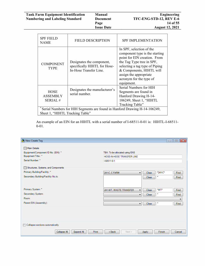
SPF FIELD NAME
FIELD DESCRIPTION
SPF IMPLEMENTATION
COMPONENT TYPE
Designates the component, specifically HIHTL for Hose-In-Hose Transfer Line.
In SPF, selection of the component type is the starting point for EIN creation. From the Tag Type tree in SPF, selecting a tag type of Piping & Components, HIHTL will assign the appropriate acronym for the type of equipment.
HOSE ASSEMBLY
SERIAL #
Designates the manufacturer’s serial number.
Serial Numbers for HIH Segments are found in Hanford Drawing H-14-106249, Sheet 1, “HIHTL Tracking Table”
* Serial Numbers for HIH Segments are found in Hanford Drawing H-14-106249, Sheet 1, “HIHTL Tracking Table”
An example of an EIN for an HIHTL with a serial number of I-68511-0-01 is: HIHTL-I-68511-0-01.

Tank Farm Equipment Identification Numbering and Labeling Standard
Manual Document Page Issue Date
Engineering TFC-ENG-STD-12, REV E-6
15 of 55 August 12, 2021
An example of an EIN for an HIHTL with a serial number of I-63204-0-01 is “HIHTL-I-63204-0-01.”
3.2.2.3 Waste Transfer Line Spacers
The following are specific requirements for establishing the EINs for Waste Transfer Line Spacers. General requirements are listed previously in Section 3.2.1.
APVP - WT- SPACER - 001
SEQUENCEBUILDING /FACILITY
PRIMARY SYSTEM
COMPONENT TYPE

Tank Farm Equipment Identification Numbering and Labeling Standard
Manual Document Page Issue Date
Engineering TFC-ENG-STD-12, REV E-6
16 of 55 August 12, 2021
SPF FIELD NAME FIELD DESCRIPTION SPF IMPLEMENTATION
PRIMARY BUILDING/ FACILITY
Designates Building/Facility where equipment or component is located and the Pit or Structure at either terminus of the line. These fields are completed by identifying the “Building / Facility” in SPF. For all WRPS controlled facilities and locations in SPF, SPF includes a location designator specific to that facility/location e.g., selecting 241-APVP as the “primary Location” in SPF will assign APVP as the farm/location identifier.
These fields are completed by identifying the Primary Location i.e., “Primary Building / Facility” in SPF. For all WRPS controlled facilities and locations in SPF, SPF includes a location designator specific to that facility/location e.g., selecting 241-APVP as the “primary Location” in SPF will assign APVP as the farm/location identifier.
PRIMARY SYSTEM
Designates system with which equipment or component is associated. In SPF, selecting from the “Items” list, “Systems” will assign the appropriate acronym for the System, in this example, 241-WT for Waste Transfer.
These fields are completed by identifying the “Primary System” in SPF.
COMPONENT TYPE
Designation is SPACER for Waste Transfer Line Spacers. In SPF, selecting a tag type of “Piping and Components,” “Spacer” will assign the appropriate acronym for the type of equipment, in this example, “Spacer.”
These fields are completed by identifying the “Component Type” in SPF.
*SEQUENCE #
Designates the unique number assigned to a particular Waste Transfer Line Spacer. SPF auto generates the next available sequential number. Use the “Start At” feature to assign a Sequence number.
These fields are completed by identifying the “Sequence #” in SPF.
*Sequence numbers for waste transfer line spaces are assigned and tracked on Hanford Drawing H-14-109724, sheet 1 (Access to this drawing requires permission for – ECI), “Nozzle Spacer.”

Tank Farm Equipment Identification Numbering and Labeling Standard
Manual Document Page Issue Date
Engineering TFC-ENG-STD-12, REV E-6
17 of 55 August 12, 2021
3.2.3 Jumpers Equipment Identification Numbering
There are two general types of jumpers, rigid and flexible. Flexible jumpers are further divided into Flexible-Metal Hose Jumpers (FMJ) and Ethylene Propylene Diene Monomer Hose jumpers (EPDMJ).
3.2.3.1 Rigid Jumper Equipment Identification Numbering Convention The following are specific requirements for establishing EINs for rigid jumpers. General requirements are listed previously in Section 3.2.1.
ANB-WT-J-[R7-R9-(B)-(C)]
CONNECTIONSBUILDING /FACILITY
PRIMARY SYSTEM
COMPONENT TYPE

Tank Farm Equipment Identification Numbering and Labeling Standard
Manual Document Page Issue Date
Engineering TFC-ENG-STD-12, REV E-6
18 of 55 August 12, 2021
SPF FIELD
NAME FIELD DESCRIPTION
PRIMARY BUILDING / FACILITY
Designates Building/Facility where equipment or component is located and the Pit or Structure at either terminus of the line. These fields are completed by identifying the Primary Location in SPF i.e., “Primary Building / Facility.” For all WRPS controlled facilities and locations in SPF, SPF includes a location designator specific to that Building/Facility/Portable Type location e.g., selecting 241-AN-01A as the “primary Location” in SPF will assign AN01A as the farm/location identifier.
PRIMARY SYSTEM
Designates system with which equipment or component is associated. In SPF, selecting from the “Items” list, “Systems” will assign the appropriate acronym for the “Primary System,” in this example, 241-WT for Waste Transfer.
COMPONENT
TYPE
Designation is “J” for Jumper.
CONNECTIONS Use brackets [ ] to show connection points on the jumper as shown in the P&IDs and Piping Diagrams. Use parentheses, ( ), to indicate the PUREX Nozzle that connects to another jumper.
An example of an EIN for a rigid jumper in pit ANW01A with connections points to nozzles 5, 6 & 15 is: AN01A-WT-J-[(5)-(6)-(15)]. Another example of a jumper with connection points R7 and R9 and B and C (where B & C are PUREX Nozzles for connection to other jumpers) is: ANB-WT-J-[R7-R9-(B)-(C)]. An example of a rigid jumper, called a slurry manifold assembly with 5 PUREX Nozzle connections to other jumpers, in a portable waste retrieval structure is: POR209-WT-J-[(10-11-12-13-14)]. NOTE: If a complex jumper with many connections is required and following the standard format, an EIN with an abbreviated connection string would be AN01A-WT-J-[A-B-C-E-F-G-H-I-J-K-L-M], which would have 36 characters and exceed the maximum character limit. Instead, an EIN such as AN01A-WT-J-[A to M], which would meet the 30-character limit, could be created.

Tank Farm Equipment Identification Numbering and Labeling Standard
Manual Document Page Issue Date
Engineering TFC-ENG-STD-12, REV E-6
19 of 55 August 12, 2021
3.2.3.2 Flexible-Metal Hose Jumpers The following are specific requirements for establishing EINs for flexible-metal hose jumpers. General requirements are listed previously in Section 3.2.1. If the jumper is relocated either to another connection point within the pit or structure or to another pit or structure, the EIN tag would be updated in SPF and set to the “Discontinued” Work Log Type. A new tag would then need to be created. Complex jumpers may contain welded piping elements plus flexible-metal hoses. These are considered to be flexible-metal hose jumpers for naming purposes.
AN01A‐WT‐FMJ‐A‐D‐(MFG SERIAL #)
SERIAL NUMBER
BUILDING / FACILITY PRIMARY SYSTEM COMPONENT
TYPECONNECTIONS

Tank Farm Equipment Identification Numbering and Labeling Standard
Manual Document Page Issue Date
Engineering TFC-ENG-STD-12, REV E-6
20 of 55 August 12, 2021
SPF FIELD
NAME FIELD DESCRIPTION
PRIMARY BUILDING/ FACILITY
Designates Building/Facility where equipment or component is located as well as, tank, pit, or other structure the equipment or component is located in, on, or near. Items not directly related to a specific structure location are identified by the general area where they are located (241, 244, 151, etc.).
PRIMARY SYSTEM
Designates system with which equipment or component is associated.
COMPONENT TYPE
Describes equipment or component function, SPF will auto populate with “FMJ” for Flexible-Metal Hose Jumpers.
CONNECTIONS Designates the connection points in the pit for both ends of the jumper as shown in the P&IDs and Piping Diagrams.
MFG SERIAL # Designates the Manufacturer’s Serial No. if assigned. (Note: The serial number is not required.) Add the serial number in brackets [ ] in the “Connections” field after the connection points.
A fictitious example of an EIN for a flexible-metal hose jumper between connection points A and D in the AN01A pit is: AN01A-WT-FMJ-A-D (SS123-4567A). If there were no assigned manufacturer’s serial number, the EIN would be: AN01A-WT-FMJ-A-D.
3.2.3.3 EPDM Hose Jumpers
The following are specific requirements for establishing EINs for EPDM hose jumpers. General requirements are listed previously in Section 3.2.1. If the jumper is relocated either to another connection point within the pit or structure or to another pit or structure, the EIN tag would be updated in SPF and set to the “Discontinued” Work Log Type. A new tag would then need to be created.

Tank Farm Equipment Identification Numbering and Labeling Standard
Manual Document Page Issue Date
Engineering TFC-ENG-STD-12, REV E-6
21 of 55 August 12, 2021
SERIAL NUMBER
AN06A‐WT‐EPDMJ‐A‐D‐(MFG SERIAL #)
BUILDING /FACILITYPRIMARY SYSTEM
COMPONENT TYPE
CONNECTIONS
SPF FIELD NAME
FIELD DESCRIPTION
PRIMARY BUILDING / FACILITY
Designates Building/Facility, tank, pit, or other structure the equipment or component is located in, on, or near. Items not directly related to a specific structure location are identified by the general area where they are located (241, 244, 151, etc.).
PRIMARY SYSTEM
Designates system with which equipment or component is associated.
COMPONENT TYPE
Describes equipment or component function, SPF will auto populate with “EPDMJ” for EPDM Hose Jumpers.
CONNECTIONS Designates the connection nozzles in the pit for both ends of the jumper as shown in the P&IDs and Piping Diagrams.
MFG SERIAL # Designates the Manufacturer’s Serial No. if assigned. (Note: The serial number is not required field.). Add the serial number in parentheses in the “Connections” field after the connection points.
An example of an EIN for an EPDM jumper between connection points F and 5 in the portable box POR104 is: POR104-WT-EPDMJ-F-5 (I-xxxx). If there were no assigned manufacturer’s serial number or if it is unknown which serial number of several identical jumpers in the structure connect from F to 5, the EIN would be: POR104-WT-EPDMJ-F-5.

Tank Farm Equipment Identification Numbering and Labeling Standard
Manual Document Page Issue Date
Engineering TFC-ENG-STD-12, REV E-6
22 of 55 August 12, 2021
3.2.4 Other Transfer System Elements Equipment Identification Numbering Convention 3.2.4.1 Hose-In-Hose Adapters
The following are specific requirements for establishing EINs for hose-in-hose adapters. Hose-in-hose adapters are those elements of primary piping used to connect hose-in-hose transfer lines to other retrieval piping components, e.g., a jumper. The following are typical adapters:
Primary hose PUREX connector (H-14-105309 Sheet 1): This adapter has a hose
connector on one end with a PUREX nozzle on the other. It is used to connect a HIHTL segment to a flexible jumper in a portable valve or distribution box.
Spool Assembly (H-14-107391 Sheet 8): This adapter is a section of stainless steel pipe
with a hose connector on both ends. These are used to connect two segments of HIHTL or a HIHTL to another piping element such as the primary hose PUREX connector described above.
The HIHAD component acronym for a HIH Adapter will be used regardless of the design.
SPF FIELD
NAME FIELD DESCRIPTION
PRIMARY BUILDING / FACILITY
Designates Building/Facility, tank, pit, or other structure the equipment or component is located in, on, or near. Items not directly related to a specific structure location are identified by the general area where they are located (241, 244, 151, etc.).
PRIMARY SYSTEM
Designates system with which equipment or component is associated.
COMPONENT TYPE
Describes the type of equipment, SPF will auto populate with “HIHAD” for hose-in-hose adapters.
CONNECTION Describes the port or nozzle location in the pit or structure associated with the adapter.
SEQUENCE Unique sequence designator (e.g., 1, 2, or 3) identifies one or more adapters in line at that connection.
SEQUENCE
POR104 – WT – HIHAD ‐ A ‐ 1
BUILDING / FACILITYPRIMARY SYSTEM COMPONENT
TYPE CONNECTION

Tank Farm Equipment Identification Numbering and Labeling Standard
Manual Document Page Issue Date
Engineering TFC-ENG-STD-12, REV E-6
23 of 55 August 12, 2021
An example of an EIN for a Hose-In-Hose Adapter is: POR104-WT-HIHAD-A-1 assigned to a Spool Assembly located relative to Port or hose position A. For this example, a second Hose-In-Hose Adapter is connected to this Spool Assembly. The EIN for the adjacent adapter is: POR104-WT-HIHAD-A-2 assigned to a Floor Nozzle Assembly.
3.2.4.2 PUREX Type Process Blank
The following are specific requirements for establishing EINs for PUREX Type Process Blanks. General requirements are listed previously in Section 3.2.1. If a PUREX Type Process Blank is relocated, only the location would be updated in SPF; the EIN would NOT change. However, a revision to the Routing Board drawing, H-14-107346, Sheet 1 would be required. An example of the naming convention for PUREX Type Process Blanks is:
DATABASE FIELD NAME
FIELD DESCRIPTION
COMPONENT Describes equipment or component function, SPF will auto populate with “PPB” signifying a PUREX Process Blank.
ENS Sequence Designates the number assigned to a particular PUREX Process Blank wherever it is located. This is a manually assigned 3 digit number.
Unique Numbers assigned to PPBs are found in Routing Board drawing # H-14-107346, Sheet 1.
PPB - 001
COMPONENT UNIQUE NUMBER

Tank Farm Equipment Identification Numbering and Labeling Standard
Manual Document Page Issue Date
Engineering TFC-ENG-STD-12, REV E-6
24 of 55 August 12, 2021
An example of an EIN for a PUREX Process Blank installed on Nozzle G in the ANA valve pit is: PPB-001. Refer to Item 9 of Table A-1 for the approved EIN numbering deviations associated with PUREX Process Blanks that have assigned numbers.

Tank Farm Equipment Identification Numbering and Labeling Standard
Manual Document Page Issue Date
Engineering TFC-ENG-STD-12, REV E-6
25 of 55 August 12, 2021
3.2.4.3 Chemical Connector Process Blank
The following are specific requirements for establishing EINs for Chem Process Blanks. General requirements are listed previously in Section 3.2.1. Chem Connector process blanks are attached to hose couplings as opposed to a PUREX type nozzle. Hose connections can include standard hydraulic hoses or the type of connections used for the Hose-in-hose transfer system hoses and associated adapters. If a Chem Connector Process Blank is relocated, the EIN would NOT change. However, a revision to the Routing Board drawing, H-14-107346, Sheet 1 would be required. An example of the naming convention for Chem Process Blanks is:
DATABASE FIELD NAME
FIELD DESCRIPTION
COMPONENT Describes equipment or component function, SPF will auto populate with “CHEMPB” signifying a Chem Process Blank.
ENS Sequence Designates the Unique No. for a particular Chem Process Blank wherever it is located. This is a manually assigned 3-digit number.
Unique Numbers assigned to CHEMPBs are found in Routing Board drawing # H-14-107346, Sheet 1.
An example of an EIN for a CHEM Process Blank installed on a HIHTL segment is: CHEMPB-001. Refer to Item 10 of Table A-1 for the approved EIN numbering deviations associated with CHEM Process Blanks that have assigned numbers.
CHEMPB-001COMPONENT UNIQUE NUMBER

Tank Farm Equipment Identification Numbering and Labeling Standard
Manual Document Page Issue Date
Engineering TFC-ENG-STD-12, REV E-6
26 of 55 August 12, 2021

Tank Farm Equipment Identification Numbering and Labeling Standard
Manual Document Page Issue Date
Engineering TFC-ENG-STD-12, REV E-6
27 of 55 August 12, 2021
3.2.4.4 Tank Return (Numbered Riser Inlet Connection and In Pit Piping)
The following are specific requirements for establishing EINs for numbered risers in pits that are used as tank returns (drop legs). Typically, these risers are part of the original tank construction consisting of a 4 inch, Schedule 40 pipe that extends through the floor of the pit and through the tank dome, terminating in the headspace of the tank. The end of the pipe is capped with a PUREX nozzle. The safety–significant portion of the riser is that portion of pipe that extends above the pit floor and the nozzle. An example of the naming convention for the Tank Return (Numbered Riser Inlet Connection and In Pit Piping) is:
SPF FIELD NAME
FIELD DESCRIPTION
PRIMARY BUILDING/ FACILITY
Designates Building/Facility, tank, pit, or other structure the equipment or component is located in, on, or near. Items not directly related to a specific structure location are identified by the general area where they are located.
PRIMARY SYSTEM
Designates system with which equipment or component is associated.
COMPONENT Describes equipment or component function, SPF will auto populate with “RISER” signifying a riser.
ASSIGNED NUMBER
Designates the assigned number of the riser. (Enter number without leading zeros)
NOZZLE # Designates the Label or Number of the Nozzle as shown on the P&ID on the routing board, or on the electronic routing board. SPF will automatically add the parentheses.
AN01A-WT-RISER-013-(Nozzle #)
BUILDING /FACILITY
PRIMARYSYSTEM
COMPONENT NOZZLE #NUMBER

Tank Farm Equipment Identification Numbering and Labeling Standard
Manual Document Page Issue Date
Engineering TFC-ENG-STD-12, REV E-6
28 of 55 August 12, 2021
An example for a tank return in the AW06A pump pit using 4-inch riser number 005 labeled G on the P&ID and pit drawings is: AW06A-WT-RISER-005 (G).

Tank Farm Equipment Identification Numbering and Labeling Standard
Manual Document Page Issue Date
Engineering TFC-ENG-STD-12, REV E-6
29 of 55 August 12, 2021
3.2.4.5 Tank Return Equipment Mounted in a Riser
The following are specific requirements for establishing EINs for tank returns that are separate items of equipment mounted in a riser. The safety-significant portion of the tank return is that portion of pipe that extends above the pit floor and the nozzle. The naming convention for the Tank Return is:
SPF FIELD NAME FIELD DESCRIPTION
PRIMARY BUILDING / FACILITY
Designates Building/Facility, tank, pit, or other structure the equipment or component is located in, on, or near. Items not directly related to a specific structure location are identified by the general area where they are located.
PRIMARY SYSTEM
Designates system with which equipment or component is associated.
COMPONENT Describes equipment or component function, specifically TKR signifying the component type for Tank Return Equipment Mounted in Riser.
NUMBER Designates the assigned number of the tank return.
NOZZLE #
Designates the Label or Number of the Nozzle as shown on the P&ID on the routing board, or on the electronic routing board. SPF will automatically add the parentheses.
An example for a tank return is: AP02A-WT-TKR-101 (3-1, 3-2 & 3-3). This tank return is mounted in the AP02A pit and has three nozzle connections.
AN01A-WT-TKR-201-(Nozzle #)
BUILDING /FACILITY
PRIMARYSYSTEM
COMPONENTTYPE
NOZZLE #NUMBER

Tank Farm Equipment Identification Numbering and Labeling Standard
Manual Document Page Issue Date
Engineering TFC-ENG-STD-12, REV E-6
30 of 55 August 12, 2021
3.2.4.6 Miscellaneous Equipment that Contain Integral Items of Safety-Significant Primary Piping
The following are types of equipment that would incorporate segments of Safety-Significant Primary Piping in the design.
Transfer Pumps: Safety-significant piping includes the discharge nozzle and any piping
that extends above the riser. Note that some pumps may contain integral tank returns and in some cases dilution piping that could be used as a tank return.
Sluicers: The safety-significant piping in a sluicer includes the inlet nozzle or
connection and any piping that extends above the riser.
Air-Lift Circulators: A typical air-lift circulator (ALC) incorporates one or more tank returns. The Safety-Significant portion of an ALC is the inlet nozzle or connection and any piping that extends above the riser.
The naming convention for these items will follow the convention described in Section 3.2.1 above where the portions of the item that are considered to be safety-significant will be described in the Safety Equipment List.

Tank Farm Equipment Identification Numbering and Labeling Standard
Manual Document Page Issue Date
Engineering TFC-ENG-STD-12, REV E-6
31 of 55 August 12, 2021
3.2.5 Ground Fault Circuit Interrupter
The following are specific requirements for establishing EINs for Ground Fault Circuit Interrupters (GFCI). The naming convention for a GFCI is:
GFCI-01591
Number Component Type
SPF FIELD NAME FIELD DESCRIPTION
PRIMARY BUILDING/FACILITY
Designates tank farm, building, or other structure the equipment or component is located in, on, or near. Not used in EIN but must be populated.
PRIMARY SYSTEM
Designates system with which equipment or component is associated. Not used in EIN but must be populated.
COMPONENT Describes equipment or component function, specifically GFCI signifying the component type for Ground Fault Circuit Interrupter.
NUMBER Designates the assigned number of the GFCI. ENS Sequence Suffix This field is not required for GFCI EINs.

Tank Farm Equipment Identification Numbering and Labeling Standard
Manual Document Page Issue Date
Engineering TFC-ENG-STD-12, REV E-6
32 of 55 August 12, 2021
3.2.6 Ground Fault Equipment Protection
The following are specific requirements for establishing EINs for Ground Fault Equipment Protection (GFEP). The naming convention for a GFEP is:
\
SPF Field Name Field Description
PRIMARY BUILDING/ FACILITY
Designates Building/Facility, or other structure the equipment or component is located in, on, or near. Not used in EIN but must be populated.
PRIMARY SYSTEM
Designates system with which equipment or component is associated. Not used in EIN but must be populated.
COMPONENT Describes equipment or component function, specifically GFEP signifying the component type for Ground Fault Equipment Protection.
NUMBER Designates the assigned number of the GFEP.
ENS Sequence Suffix This field is not required for GFEP EINs.

Tank Farm Equipment Identification Numbering and Labeling Standard
Manual Document Page Issue Date
Engineering TFC-ENG-STD-12, REV E-6
33 of 55 August 12, 2021
3.3 Labeling Requirements
Approved deviations for Labeling and EIN identification on drawings are listed in Table A-2 of Attachment A.
3.3.1 General Labeling Requirements
1. All labels are generated from the required data and specifications maintained in SPF and require the following. When requesting a permanent label, provide maintenance with the following:
Label size-see 3.3.3 (Identify in SPF for the EIN) Number of label sides (Identify in SPF for the EIN) Label material Number of drilled holes, if any.
2. All label data must be in SPF before the label is created, and shall include the following:
The unique assigned EIN--auto populated by SPF
Title: Provide a meaningful component description to be displayed on the label, e.g., “Isolation valve to XYZ”
Sub-Title: This is a continuation of the “Title” field, as needed
Fed From: This field is to capture information on where the power for the component is supplied from, see Section 3.3.1.3
Barcode--auto populated by SPF upon creation of new components, see Section
3.3.1.2 below. The barcode does not appear on plastic labels.
3. If labels are being generated by a vendor, provide the vendor with:
Details from this standard, TFC-ENG-FACSUP-C-23, and Section 3.3.1 Requirements such as: font, size, etc. Required data and specifications maintained in SPF for the component The material to use for the label, i.e. metal or plastic (see Section 3.3.2) The number and location of the holes in the label, if any. (5.1.4)
3.3.1.1 Equipment Description
1. The 64-character description on RPP labels is comprised of two 32-character, alphanumeric fields (field length restricted to 25 characters on NL format labels). These fields are contained in the SPF “Edit Tag” form in the “Label Details” section, as Title and Sub-Title.
2. Since the field is broken into two 32-character fields, no word wrap is available. When
completing this information, ensure the description makes sense, since it will appear as two stacked and centered lines.

Tank Farm Equipment Identification Numbering and Labeling Standard
Manual Document Page Issue Date
Engineering TFC-ENG-STD-12, REV E-6
34 of 55 August 12, 2021
3. If space permits, the entire description is spelled out.
4. If space is insufficient for complete spelling, abbreviations are selected in the following
order:
ASME Y14.38, “Abbreviations and Acronyms for Use on Drawings and Related Documents”
For items not covered by ASME Y14.38, use the Institute of Electrical and
Electronics Engineers (IEEE), “Standard Dictionary of Electrical and Electronic Terms”
If a suitable abbreviation cannot be located, develop a good, common sense
abbreviation. 3.3.1.2 Barcode
1. A unique barcode number is assigned in SPF when generating a new EIN and will be shown on each metal engraved permanent label fabricated and installed in Tank Farm facilities. Some existing EINs, in SPF, may not have a barcode, however, efforts are underway to add them. The barcode shall comply with Hanford Site standards for barcode development using the “3 of 9” code structure.
2. Barcode numbers, for Tank Farm facilities, will be structured as follows (S123456WT),
where “S” and “WT” remain constant on each label as a ready reference to identify TOC equipment, with a unique 6-digit (000001 to 999999) sequence number between.
3. Barcodes are optional for ETF, LERF, TEDF, Tank Side Cesium Removal (TSCR), or
242-A facilities, since these facilities did not use barcodes when originally labelled. 3.3.1.3 Power Supply Breaker Data (Fed From)
1. The “Power Supplied From” field, in SPF, provides power source information for electrically powered equipment.
2. Fed from source on labels shall be the nearest upstream disconnect device. 3. When possible, descriptive locating information is listed rather than power source EIN
(e.g., “MCC-001, Cubicle A-2” vs. EIN assigned to that cubicle).
3.3.1.4 Materials
1. For on-site fabricated labels, the following materials are standard: Laser-engraved stainless steel (2B Matte Finish preferred) Stainless steel labels
are excellent for harsh or corrosive environments; however, they are difficult to read in direct light and at night. For this reason, black anodized aluminum with Matte Finish is recommend when in direct light or at night.

Tank Farm Equipment Identification Numbering and Labeling Standard
Manual Document Page Issue Date
Engineering TFC-ENG-STD-12, REV E-6
35 of 55 August 12, 2021
Laser engraved black anodized aluminum with a Matte Finish. The aluminum
label cannot be used in harsh or corrosive environments.
Component tags are typically made at the Hanford sign shop; however, the EIN must already exist in SPF. Tags can be ordered using the Sign Shop’s Order Request.
2. For labels fabricated offsite by vendors, the following materials are standard:
All materials acceptable for on-site labels, plus
Anodized photosensitized aluminum base (Metalphoto®, reference
https://www.mpofcinci.com/, or similar). Finish shall be specified as Satin or Matte to avoid reflectivity. Labels shall be specified to provide black lettering on an aluminum background. This label material provides high durability, high visibility labels.
Ceramic Marked Stainless Steel. This label material provides high durability,
high visibility labels.
Specifications for tags from vendors must include all required label information per Section 3.3.1 of this standard.
3. Where labels may come into contact with exposed electrical connections, plastic labels,
shall be used. Plastic labels shall: Use quality material suitable for the application.
Typically, for engraved labels two-ply, colored plastic, white background with
black letters are used. Other color combinations may be used to indicate specific systems (e.g., red background with white letters for fire systems).
Outdoors or in high temperature environments use plastic labels only when
specifically approved for the application by the label point of contact.
4. Thickness: For labels attached with fasteners or hung from cable the thickness of the plate shall be not less than 0.02 inches. For labels attached using adhesives, the thickness shall be not less than 0.012 inch and not greater than 0.025 inch.
5. Weathering: Label material and/or adhesive shall be specified to meet weathering using
ASTM D4329 and UVA 340 lamps. After 7,000 hours of exposure in a QUV weathering deck, the label shall remain adhered and readable.

Tank Farm Equipment Identification Numbering and Labeling Standard
Manual Document Page Issue Date
Engineering TFC-ENG-STD-12, REV E-6
36 of 55 August 12, 2021
3.3.2 Label Sizing
1. There are eight standard label sizes as indicated below:
Label Size Code:
Height Width # of Lines Label Size
Code Figure Number
NL 1.00 2.00 5 CA 3 13 1.50 2.50 5 BO 7
NM 1.50 2.50 6 BO 6 NH 1.50 3.00 7 C0 2 NJ 2.00 4.00 5 E5 8 NE 2.00 7.00 7 E1 5 NF 2.5 4.00 7 B2 1 NK 4.00 13.75 7 E4 4
3.3.3 Label Format
1. Font - USE ALL CAPITAL SIMPLE BLOCK TYPE FONT, Arial or Helvetica. All
labels in a given area shall be of the same font.
2. Primary label information letters shall be 3/16-inch high (minimum) (~14 point font), unless space prohibits this height.
3. Secondary label information letter height shall be 1/8-inch high (minimum) (~9 point
font) unless space prohibits this height.
4. Character width-to-height ratio and inter-character spacing shall be such that all letters are clearly distinguishable from one another under typical viewing conditions for the installed location.
5. Spacing between words shall be at least one full character width.
6. Spacing between lines on the label shall typically be at least one times the character
height of the line being printed (e.g., if one line is 3/16 inch and the next line is 1/8 inches, at least 1/8-inch spacing is required.)
7. When viewing distance, lighting conditions, etc., require, label size shall be increased, as
necessary, to ensure label readability.
8. As label size is increased, lettering, word, and line dimensions shall be increased proportionally.
9. Control panels should use a structured size graduation as shown in Figure 8.
10. In all cases, label size and lettering shall be such that each character, word, and line are
clearly distinguishable from adjacent characters, words, and lines under typical viewing conditions for the installed location.

Tank Farm Equipment Identification Numbering and Labeling Standard
Manual Document Page Issue Date
Engineering TFC-ENG-STD-12, REV E-6
37 of 55 August 12, 2021
3.3.4 Attaching Labels
1. Labels may be attached to the equipment using vendor supplied adhesive or screws, or hung with stainless steel aircraft cable, as best suited to the application:
Stainless cable shall be 0.063 inches in diameter in a 7 x 7 strand matrix and
fastened with wire crimps of zinc/copper material sized for the cable.
Acrylic adhesives, including die-cut 30 mil foam with acrylic adhesive on both sides, shall be used. For heavy duty applications, vendor recommended label adhesives are used. On-site, RTV-108 adhesive sealant (supply number 17349404) or double-backed adhesive tape can be used, as best suited to the application.
2. Label adhesive performance: The adhesive shall be a 0.001-inch thick acrylic adhesive
having the following minimum values:
Peel Strength at 70°F with a 72 hour dwell
Stainless steel/aluminum 80 ounces/inch of width
Shear Strength at 70°F 15 hours
3.3.5 Label Placement
1. Labels shall be placed:
To be readily visible and readable
Horizontal (except hanging labels)
To eliminate identity confusion
So they will not be easily damaged or cause hazard to the operator
To avoid obscuring indications or interfering with equipment operation.
2. Labels are placed on flat surfaces to the extent possible:
On pipes, place the label along the horizontal run vs. around the pipe.
On motors, tanks, and other curved surfaces, locate the flattest portion, which also meets criteria for ready visibility and readability.
3. Large equipment (generators, vessels, etc.) are labeled in multiple locations.
4. Design labels for the environment in which they will be used (e.g., use heat or radiation
resistant material in applicable areas.)

Tank Farm Equipment Identification Numbering and Labeling Standard
Manual Document Page Issue Date
Engineering TFC-ENG-STD-12, REV E-6
38 of 55 August 12, 2021
5. Valve and damper labels should not interfere with linkage and valve operators. Where
possible, attach the label to the valve yoke using care to avoid damaging the valve stem. Do not thread label plates and connecting wire through valve hand wheel, operating chains, damper linkages, or removable T-handles.
6. Both ends of the extension (reach rod) of remote, mechanically operated valves are labeled.
7. Chain operated valves are labeled at the valve and on a metal ring through which the chain easily passes, so the label is always at the bottom of the chain loop.
8. If the valve cannot be clearly seen, OPEN or CLOSE directional arrows are included at the chain.
9. Wire is not used to hang tags inside electrical equipment.
3.3.6 Label Verification
1. Labels shall be verified against design and safety basis documentation and drawings to ensure consistency in accordance with:
TFC-ENG-DESIGN-C-56 TFC-ENG-DESIGN-D-51 TFC-ENG-DESIGN-P-17.
Before installing, labels shall be verified against procedures, lineup sheets, round sheets, and other facility documents to ensure consistency in accordance with, TFC-PLN-05.
3.3.7 Temporary Labels
1. Temporary labels are used to temporarily label tank farm equipment until a permanent label is received and are managed and installed in accordance with TFC-OPS-OPER-C-32.
3.3.8 Electrical Equipment
Labeling electrical components, such as motor control centers (MCCs), shall follow TFC-ENG-STD-41 and the National Electrical Code (NEC).
Information labels that identify essential drawings and vendor information may be placed
on other electrical equipment as desired by Operations and Maintenance.
Control threshold switches are labeled for their function.
Switches are labeled with position (ON-OFF, HAND-OFF-AUTO, etc.) indication and direction of operation, as necessary.

Tank Farm Equipment Identification Numbering and Labeling Standard
Manual Document Page Issue Date
Engineering TFC-ENG-STD-12, REV E-6
39 of 55 August 12, 2021
3.3.9 Motor Control Centers
The following specific label information is required by the NEC code: Aluminum label cannot be used in harsh or corrosive environment.
Rated voltage, number of phases, supply power source, type (normal, standby, or
emergency), and location MCC breakers not providing a power source shall be labeled “SPARE”
Distribution panel breaker loads are identified inside the panel. Where space prohibits
listing breaker loads, place breaker information on a panel schedule inside the panel door. Lighting loads list building area and elevation served
Control panels (graphic and non-graphic) are labeled with single or multiple entry points at each section of the panel with individual identifiers on the front and back of each panel.
Information labels that identify essential drawings and vendor information may be placed on motor control centers and electrical distribution panels if desired by Operations and Maintenance.
4.0 DEFINITIONS
Consumables/Consumable Item. (1) Items or materials that lose their identity and are incorporated into another item when used (e.g., lubricants, paint, weld filler), or (2) items that are purchased in quantity and not tracked individually or labeled beyond any identification supplied by the manufacturer.
Equipment/Component. Uniquely identified hardware installed at specific locations as specified in WRPS engineering documents. A component may be an individual device (such as a breaker, valve, pump, or vessel) or it may be complex equipment (such as a boiler, compressor skid, instrument rack, or control panel).
Equipment/Component Identification Number (ECIN). A WRPS configured alphanumeric string that uniquely identifies a component / subcomponent using the WRPS scheme and format. The component tag number is generated by and contained in SPF.
Equipment/Component Noun Name. A word description of a component based on its location, type, use, and function. The Component Noun Name is determined with the objective of making the noun name useful to operators and maintenance personnel throughout the life of the plant. The noun name is documented in SPF.
Equipment/Component Tag Number. A unique equipment/component identification consisting of a locator, system identifier, equipment/component type and sequence number.
Label. A physical tag or marking containing the equipment/component tag number, equipment/ component noun name, and other information prescribed in this standard to uniquely identify equipment and components in WRPS operating facilities.

Tank Farm Equipment Identification Numbering and Labeling Standard
Manual Document Page Issue Date
Engineering TFC-ENG-STD-12, REV E-6
40 of 55 August 12, 2021
Subcomponent. Uniquely identified piece of a component that must be acted upon by an individual for isolation, manipulation, control, adjustment, or maintenance. Note that all pieces of a component are subcomponents.
System boundary. A boundary defines where two systems interface. The boundary exists at an isolation valve, an electrical breaker, a piping connection point, or some other physical location that can be identified in the field and/or on a drawing.
5.0 SOURCES 5.1 Requirements
5.1.1 ANSI/ASME A13.1, “Pipe Labeling to ANSI-ASME A13.1.”
5.1.2 DOE O 422.1, “Conduct of Operations.” 5.1.3 RPP-14541, “Jumper Fabrication and Testing Specification for Tank Farms.” 5.1.4 TFC-ENG-FACSUP-C-23, “Equipment Identification and Data Management.” 5.1.5 TFC-PLN-05, “Conduct of Operations Implementation Plan.” 5.1.6 ANSI/ISA 5.1 (2009), “Instrumentation Symbols and Identification.”
5.2 References
5.2.1 ASME Y14.38, “Tank Farm Safety Instrumented Code of Record, Abbreviations and Acronyms for Use on Drawings and Related Documents.”
5.2.2 IEEE, “Standard Dictionary of Electrical and Electronics Terms.”
5.2.3 TFC-ENG-DESIGN-C-56, “Modification Traveler.”
5.2.4 TFC-ENG-DESIGN-D-51, “ECN Preparation and Work Completion Walkdown.”
5.2.5 TFC-ENG-DESIGN-P-17, “Design Verification.” 5.2.6 TFC-OPS-OPER-C-32, “Farm Temporary Component Identification Tags.”

Tank Farm Equipment Identification Numbering and Labeling Standard
Manual Document Page Issue Date
Engineering TFC-ENG-STD-12, REV E-6
41 of 55 August 12, 2021
Figure 1 - NF Label Coding
Design ID: NF Label Size Code:
B2 Width: 4.00” Height: 2.50”
Line Barcode Max Char Row Hgt Just C/L/R Start Font
Ref Den Side Top
1 23 0.26 C 2.00 0.40 R-HEL-BOLD
2 32 0.17 C 2.00 0.75 R-HEL-BOLD
3 32 0.17 C 2.00 0.95 R-HEL-BOLD
4 29 0.17 C 2.00 1.35 R-HEL-BOLD
5 18 0.13 R -0.05 1.67 R-HEL-BOLD
6 6 7.1 9 0.16 C 2.00 2.30 R-HEL-BOLD
7 9 0.25 C 2.10 2.15 R-HEL-BOLD
The NF is available in one or two-sided format and can be hung or adhered with approved adhesives or acrylic adhesive backing pads. It is designed for use in harsh environments. The large size is suitable for major components such as tanks, vessels, ventilation skids, breakers, pumps, and motors.

Tank Farm Equipment Identification Numbering and Labeling Standard
Manual Document Page Issue Date
Engineering TFC-ENG-STD-12, REV E-6
42 of 55 August 12, 2021
Figure 2 - NH Label Coding
Design ID: NH Label Size Code: C0
Width: 3.00” Height: 1.50”
Line Barcode Max Char Row Hgt Just C/L/R Start Font
Ref Den Side Top
1 23 0.19 C 1.50 0.36 R-HEL-BOLD
2 32 0.13 C 1.50 0.60 R-HEL-BOLD
3 32 0.13 C 1.50 0.73 R-HEL-BOLD
4 29 0.13 C 1.50 0.99 R-HEL-BOLD
5 18 0.10 R -0.20 1.16 R-HEL-BOLD
6 9 0.11 C 1.50 1.49 R-HEL-BOLD
7 6 7.1 9 0.15 C 1.60 1.39 R-HEL-BOLD
The NH is available in one or two-sided format and can be hung or adhered with approved adhesives or acrylic adhesive backing pads. It is designed for use in harsh environments. This is the primary label for use in the tank farms. This label should be specified in all cases except for individual control panel instruments and controls, hand switches, etc., or where size prohibits.

Tank Farm Equipment Identification Numbering and Labeling Standard
Manual Document Page Issue Date
Engineering TFC-ENG-STD-12, REV E-6
43 of 55 August 12, 2021
Figure 3 - NL Label Coding
Design ID: NL Label Size Code: CA Width: 2.00” Height: 1.00”
Line Barcode Max Char Row Hgt Just C/L/R Start Font
Ref Den Side Top
1 23 0.13 C 1.00 0.20 R-HEL-BOLD
2 25 0.10 C 1.00 0.40 R-HEL-BOLD
3 25 0.10 C 1.00 0.50 R-HEL-BOLD
4 09 0.10 C 1.00 0.83 R-HEL-BOLD
5 4 7.1 09 0.10 C 1.10 0.73 R-HEL-BOLD
The NL label is available in one or two-sided format and can be hung or adhered with approved adhesives or acrylic adhesive backing pads. Description fields limited to 25 characters each No provision for FED FROM data.

Tank Farm Equipment Identification Numbering and Labeling Standard
Manual Document Page Issue Date
Engineering TFC-ENG-STD-12, REV E-6
44 of 55 August 12, 2021
Figure 4 - NK Label Coding
Design ID: NK Label Size Code: E4 Width: 13.75” Height: 4.00”
Line Barcode Max Char Row Hgt Just C/L/R Start Font
Ref Den Side Top
1 23 0.70 C 6.75 0.20 R-HEL-BOLD
2 32 0.45 C 6.75 0.85 R-HEL-BOLD
3 32 0.45 C 6.75 1.38 R-HEL-BOLD
4 18 0.25 R -0.10 2.40 R-HEL-BOLD
5 09 0.20 C 6.75 2.44 R-HEL-BOLD
6 5 4.0 09 0.45 C 6.93 2.25 R-HEL-BOLD
7 29 0.23 L 0.60 2.40 R-HEL-BOLD
The NK label is the largest label currently in use. It is available in one or two-sided format and can be hung or adhered with approved adhesives or acrylic adhesive backing pads. This label is normally used for large sized equipment, or equipment that must be viewed from a considerable distance, space permitting.

Tank Farm Equipment Identification Numbering and Labeling Standard
Manual Document Page Issue Date
Engineering TFC-ENG-STD-12, REV E-6
45 of 55 August 12, 2021
Figure 5 - NE Label Coding
Design ID: NE Label Size Code: E1 Width: 7.00” Height: 2.00”
Line Barcode Max Char Row Hgt Just C/L/R Start Font
Ref Den Side Top
1 23 0.38 C 3.50 0.45 R-HEL-BOLD
2 32 0.23 C 3.50 0.80 R-HEL-BOLD
3 32 0.23 C 3.50 1.05 R-HEL-BOLD
4 09 0.15 C 3.50 1.53 R-HEL-BOLD
5 4 7.1 09 0.20 C 3.60 1.40 R-HEL-BOLD
6 18 0.15 R 0.00 1.45 R-HEL-BOLD
7 29 0.12 L 0.45 1.45 R-HEL-BOLD
The NE is a smaller version of the NK label, also available in one or two-sided format and can be hung or adhered with approved adhesives or acrylic adhesive backing pads. This label is normally used for panel identification, such as CAM panels.

Tank Farm Equipment Identification Numbering and Labeling Standard
Manual Document Page Issue Date
Engineering TFC-ENG-STD-12, REV E-6
46 of 55 August 12, 2021
Figure 6 - NM Label Coding
Design ID: NM Label Size Code: B0 Width: 2.50” Height: 1.50”
Line Barcode Max Char Row Hgt Just C/L/R Start Font
Ref Den Side Top
1 23 0.15 C 1.25 0.13 R-HEL-BOLD
2 32 0.12 C 1.25 0.32 R-HEL-BOLD
3 32 0.12 C 1.25 0.46 R-HEL-BOLD
4 18 0.11 R -0.20 0.64 R-HEL-BOLD
5 09 0.11 C 1.25 1.00 R-HEL-BOLD
6 5 7.1 09 0.16 C 1.33 0.90 R-HEL-BOLD
The NM is available in one or two-sided format and can be hung or adhered with approved adhesives or acrylic adhesive backing pads. No provision for FED FROM data.

Tank Farm Equipment Identification Numbering and Labeling Standard
Manual Document Page Issue Date
Engineering TFC-ENG-STD-12, REV E-6
47 of 55 August 12, 2021
Figure 7 - Label (13) Coding
Design ID: 13 Label Size Code: B0 Width: 2.50” Height: 1.50”
Line Barcode Max Char Row Hgt Just C/L/R Start Font
Ref Den Side Top
1 10 0.15 C 1.25 0.13 R-HEL-BOLD
2 9 0.12 C 1.25 0.32 R-HEL-BOLD
3 20 0.12 C 1.25 0.46 R-HEL-BOLD
4 10 0.11 R -0.20 0.64 R-HEL-BOLD
5 4 7.1 10 0.16 C 1.33 0.90 R-HEL-BOLD
Label (13) is designed for Ground Fault Circuit Interrupters that will be exposed to the weather. This label is available in one or two-sided format but typically is one-sided and adhered with approved adhesives or acrylic adhesive backing pads. The preferred label that will not be exposed to the weather, is the ¼” 3M Dymo vinyl label with adhesive backing.

Tank Farm Equipment Identification Numbering and Labeling Standard
Manual Document Page Issue Date
Engineering TFC-ENG-STD-12, REV E-6
48 of 55 August 12, 2021
Figure 8 - Label (NJ) Coding THIS IS THE BLACK ANODIZED ALUMINUM LABEL USED FOR ELECTRICAL COMPONENTS
IT IS SLIGHTLY DIFFERENT THAN THE OTHERS DEPICTED IN THIS STANDARD AND AVAILABLE FROM THE SIGN SHOP.
Design ID: NJ Label Size Code: E5 Width: 4.00” Height: 2.00”
Line Barcode Max Char Row Hgt Just C/L/R Start Font
Ref Den Side Top
1 23 0.26 C 2.00 0.40 R-HEL-BOLD
2 32 0.17 C 2.00 0.75 R-HEL-BOLD
3 32 0.17 C 2.00 0.95 R-HEL-BOLD
4 29 0.17 C 2.00 1.35 R-HEL-BOLD
5 6 7.1 9 0.16 C 2.00 2.30 R-HEL-BOLD
Label NJ is available in one or two-sided format and can be hung or adhered with approved adhesives or acrylic adhesive backing pads. It is typically is a black anodized aluminum label designed for Electrical components, i.e., GFCI, GFEP, panels, etc. that will be exposed to the weather but can be made of the approved plastic described above. The aluminum label is available in one- or two-sided format but typically is one-sided and adhered with approved adhesives or acrylic adhesive backing pads. The preferred label that will not be exposed to the weather, is the ¼” 3M Dymo vinyl label with adhesive backing.

Tank Farm Equipment Identification Numbering and Labeling Standard
Manual Document Page Issue Date
Engineering TFC-ENG-STD-12, REV E-6
49 of 55 August 12, 2021
Figure 9 - Control Panel Labels
This figure is for specifying panel labeling depicted on certain drawings and not intended as a component identification label. Control Panel component identification numbering labels are shown elsewhere in this standard.

Tank Farm Equipment Identification Numbering and Labeling Standard
Manual Document Page Issue Date
Engineering TFC-ENG-STD-12, REV E-6
50 of 55 August 12, 2021
Attachment A - Approved Deviations
Table A-1 - Approved Deviations for EIN Numbering Conventions
No. TFC-ENG-STD-12 Incorporation
Section
Approved Deviation
4 1.0 EINs of equipment and piping installed in the Treated Effluent Disposal Facility (TEDF) shall comply with TFC-ENG-STD-12 and TFC-ENG-FACSUP-C-23 and H-2-815119, Sheet. 1 (Symbology only), “P&ID Disposal Station Symbols and Legends”.
6 Not Incorporated EINs for equipment and piping installed as part of the Demonstration Bulk Vitrification Project (DBVS) shall be labeled in a standardized format in accordance with the contractor’s standard labeling program. TFC-ENG-STD-12, Tank Farm Equipment Identification Numbering and Labeling Standard may be used as guidance.
7 Attachment A The EIN numbering convention on some of the leak detection terminal boxes in AP Farm Project W-314 have an approved deviation to use a non-standardized EIN. The EIN convention is in conformance with this standard except “W314” is inserted between the component field and the sequence field. The EIN format on these terminal boxes is as follows: APxxx-WT-TBX-W314-xxx
8 1.0 EIN numbering of consumables (e.g., Safety-Significant Waste Drum Vents) is exempt from this standard.
9 3.2.4 Assigned EINs for any PUREX Process Blank (PPB) that is listed as active/inactive, in the Safety Equipment Compliance section of an EIN in SPF, may keep its assigned number until such time as the PPB is removed and the original EIN permanently retired. If the PPB is to be reused, the next number in the PPB sequence is assigned with a new label affixed.
10 3.2.4 Assigned EINs for any CHEM Process Blank (CHEMPB) that is listed as active/inactive, in the Safety Equipment Compliance section of an EIN in SPF, may keep its assigned number until such time as the CHEMPB is removed and the original EIN permanently retired. If the CHEMPB is to be reused, the next number in the CHEMPB sequence is assigned with a new label affixed.

Tank Farm Equipment Identification Numbering and Labeling Standard
Manual Document Page Issue Date
Engineering TFC-ENG-STD-12, REV E-6
51 of 55 August 12, 2021
Attachment A - Approved Deviations (cont.)
Table A-1 - Approved Deviations for EIN Numbering Conventions (cont.)
No. TFC-ENG-STD-12 Incorporation
Section
Approved Deviation
11. 3.2.1 This deviation is to permit the use of currently assigned EINs for all associated C- 107 MARS equipment. The following are examples of discrepant equipment IDs:
No C-107 MARS Project Equipment ID
STD-12 Equipment ID
1 POR237-WT-PT1-154 POR237-WT-PT-154A 2 POR237-WT-PT2-154 POR237-WT-PT-154B 3 POR237-WT-FV1-155 POR237-WT-FV-155A 4 POR237-WT-FV2-155 POR237-WT-FV-155B 5 POR237-WT-FT1-154 POR237-WT-FT-154A 6 POR237-WT-FT2-154 POR237-WT-FT-154B 7 “PNL-A” in High
Pressure Water Skid 1 POR239-WT-DP-001
8 “PNL-B” in High Pressure Water Skid 1
POR239-WT-DP-002
12. 3.2.2.2 This deviation is to permit the legacy (old) Hose-in-Hose Waste Transfer Line Segments (HIHTL) in the SPF database and on drawings that did not use the “HIHTL” designator, but are only listed by their serial number, e.g. I-07243-0-01.
13. 3.2.1 This deviation is for the continued use of existing AY/AZ VTP EINs assigned under a different convention standard. EINs and labeling of equipment, piping/duct and instruments installed for the AY/AZ VTP were developed prior to the H-14-020000 standard. In addition, the EINs were constrained by the original MICON monitoring and control system and have carried forward as the control system was upgraded. As new equipment is added to the system, the current EIN standard will be used. Exceptions, which must be approved by the System Engineer, can be made in the case where the new equipment exactly duplicates an existing function and Human Factors concerns would dictate using the original naming convention.
14 3.2.1 For the AP Exhauster Installation project, equipment EINs established as part of the original AP Exhauster project with a general prefix of AP241, in lieu of building numbers required by TFC-ENG-STD-12, can be used.

Tank Farm Equipment Identification Numbering and Labeling Standard
Manual Document Page Issue Date
Engineering TFC-ENG-STD-12, REV E-6
52 of 55 August 12, 2021
Attachment A - Approved Deviations (cont.)
Table A-1. Approved Deviations for EIN Numbering Conventions (cont.)
No. TFC-ENG-STD-12 Incorporation
Section
Approved Deviation
15 3.2.1 For the SY Exhauster Installation project, equipment EINs established as part of the original SY Exhauster project with a general prefix of SY241, in lieu of building numbers required by TFC-ENG-STD-12, can be used.
16 3.2.2.2 This deviation is to permit the legacy (old) Hose-in-Hose Waste Transfer Line Segments (HIHTL) in the SPF database and on drawings that did not use the “HIHTL” designator, but are only listed by their serial number, e.g. I-07243-0-01.
17 1.0 Systems and components owned and maintained by HMIS are exempt from this standard. These includes utilities outside a facility, such as electrical power lines, feeding a facility or water utilities supplying a facility. Fire protection components maintained by HMIS, inside and outside, facilities, are also exempt from this standard.

Tank Farm Equipment Identification Numbering and Labeling Standard
Manual Document Page Issue Date
Engineering TFC-ENG-STD-12, REV E-6
53 of 55 August 12, 2021
Attachment A - Approved Deviations (cont.)
Table A-2 - Approved Deviations for Labeling and EIN Identification on Drawings
6 Not Incorporated Component identifiers for the Effluent Treatment Facility (ETF), Liquid Effluent Retention Facility (LERF), and 200 Area Treated Effluent Disposal Facility (TEDF) may be written with or without dashes. For example, AOV60A019, AOV-60A019, and AOV-60A-019 all refer to the same component. Monitor and Control System (MCS) tag numbers do not contain dashes (AOV60A019). Field labels generally contain dashes (AOV-60A-019).
7 Not Incorporated Labeling of equipment and piping installed as part of the Demonstration Bulk Vitrification Project (DBVS) shall be labeled in a standardized format in accordance with the contractor’s standard labeling program. TFC-ENG-STD-12, Tank Farm Equipment Identification Numbering and Labeling Standard may be used as guidance.
8 Attachment A The labeling convention on some of the leak detection terminal boxes in AP Farm project W-314 have an approved deviation to use a non-standardized EIN. The EIN convention is in conformance with this standard except “W314” is inserted between the component field and the sequence field. The EIN format on these terminal boxes as follows:
APxxx-WT-TBX-W314-xxx
9 1.0 Labeling of consumables (e.g., Safety-Significant Waste Drum Vents) is exempt from this standard.
10 3.2.2 Labels do not need to be installed on existing or future Safety-Significant buried waste transfer lines. EINs for Safety-Significant buried waste Transfer lines are not required to be included on drawings as long as the drawings contain the System Designator and the Line #.
11 3.2.2 Only the Manufacturer’s Serial Number is required as a label on a Hose-in-Hose Waste Transfer Line (HIHTL). EINs for Hose-in-Hose Waste Transfer lines are not required for drawings. Drawing H-14-106249, “HIHTL Tracking Table” requires only the Manufacturer’s Serial No.
12 3.2.4 Labels are not required to be affixed to tank returns, installed prior to January 31, 2010. EINs for tank returns are not required to be added to drawings as long as the drawings show the alpha/numeric connection(s) on the tank return.

Tank Farm Equipment Identification Numbering and Labeling Standard
Manual Document Page Issue Date
Engineering TFC-ENG-STD-12, REV E-6
54 of 55 August 12, 2021
Attachment A - Approved Deviations (cont.)
Table A-2 - Approved Deviations for Labeling and EIN Identification on Drawings
13 3.2.4 Labels for PUREX Process Blanks are required to have the assigned unique number but the Component Identifier, PPB, is optional.
14 3.2.4 Labels for CHEM Process Blanks are required to have the assigned unique number but the Component Identifier, CHEMPB, is optional.
15 3.2.3 Labels do not need to be affixed to jumpers installed prior to January 31, 2010. EINs for jumpers are not required to be added to drawings as long as the drawings show the pit or structure and the connection points.
16 3.2.4 Labels do not need to be affixed to Hose-in-Hose Adapters installed prior to January 31, 2010. EINs for Hose-in-Hose Adapters are not required to be added to drawings as long as the drawings show the connection and identify the item, either pictorially or as a callout.
17 3.2.4 Labels do not need to be affixed to Plutonium Uranium Extraction (PUREX) Type Process Blanks installed prior to January 31, 2010. EINs for PUREX Type Process Blanks installed prior to January 31, 2010, are not required to be added to drawings as long as the drawings show the connection and identify the item, either pictorially or as a callout.
18 3.2.4 Labels do not need to be affixed to Chem Connector Process Blanks installed prior to January 31, 2010. EINs for Chem Connector Process Blanks installed prior to January 31, 2010, are not required to be added to drawings as long as the drawings show the connection and identify the item, either pictorially or as a callout.
19 3.2.4 Labels are not required to be placed on risers in pits that are used as a tank return (drop leg). EINs for risers used as tank returns are not required to be added to drawings as long as the drawings show the riser number and/or the connection.
20 3.2.6 The labeling convention for GFCI EINs created in AX Farm Project T2R02 have an approved deviation to use a non-standardized EIN.
21 3.2.1.4 For instruments that performed multiple functions, the use of backslashes embedded in the EIN to differentiate the functions, e.g., SIS/SISH/SISL, were acceptable prior to May 20, 2019.

Tank Farm Equipment Identification Numbering and Labeling Standard
Manual Document Page Issue Date
Engineering TFC-ENG-STD-12, REV E-6
55 of 55 August 12, 2021
Attachment A - Approved Deviations (cont.)
Table A-2 - Approved Deviations for Labeling and EIN Identification on Drawings
22 3.2.1 This deviation is for the continued use of existing Primary and Annulus Ventilation stack EINs assigned using the stack designation numbers referenced and submitted as part of the NOC application submitted to WDOH. This stack designation number is generated by the HMIS facilities organization during the application process and ultimately assigned a WDOH emissions Unit Id. Annual emissions reporting and air flow testing for volumetric accuracies are tied to specific stack numbers tracked by WRPS and regulating agencies (WDOH). These stack designators/ WDOH emissions Unit IDs are currently in SPF for other systems but do not meet the numbering requirements for TFC-ENG-STD-12.