Tests of Series Arcing and Arc Fault Detection Devices in ...
47
IN DEGREE PROJECT ELECTRICAL ENGINEERING, SECOND CYCLE, 30 CREDITS , STOCKHOLM SWEDEN 2021 Tests of Series Arcing and Arc Fault Detection Devices in Low Voltage Systems GHAZAL ALQABBANI KTH ROYAL INSTITUTE OF TECHNOLOGY SCHOOL OF ELECTRICAL ENGINEERING AND COMPUTER SCIENCE
Transcript of Tests of Series Arcing and Arc Fault Detection Devices in ...
IN DEGREE PROJECT ELECTRICAL ENGINEERING,SECOND CYCLE, 30 CREDITS
, STOCKHOLM SWEDEN 2021
Tests of Series Arcing and Arc Fault Detection Devices in Low Voltage Systems
GHAZAL ALQABBANI
KTH ROYAL INSTITUTE OF TECHNOLOGYSCHOOL OF ELECTRICAL ENGINEERING AND COMPUTER SCIENCE
I
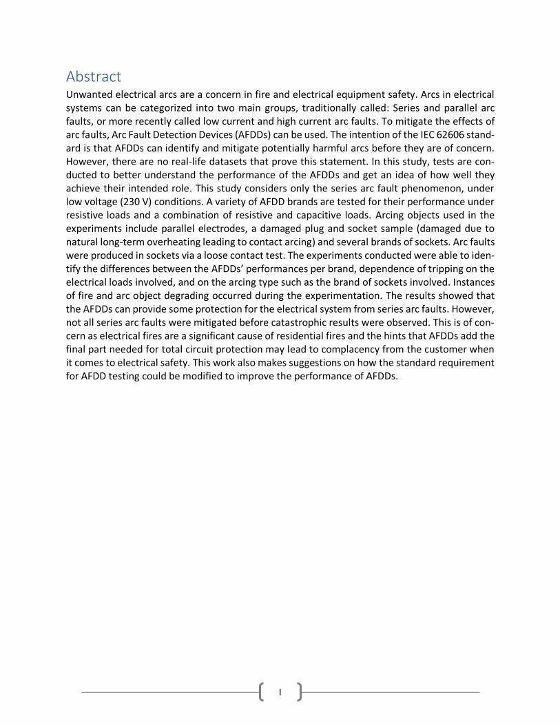
Abstract Unwanted electrical arcs are a concern in fire and electrical equipment safety. Arcs in electrical systems can be categorized into two main groups, traditionally called: Series and parallel arc faults, or more recently called low current and high current arc faults. To mitigate the effects of arc faults, Arc Fault Detection Devices (AFDDs) can be used. The intention of the IEC 62606 stand-ard is that AFDDs can identify and mitigate potentially harmful arcs before they are of concern. However, there are no real-life datasets that prove this statement. In this study, tests are con-ducted to better understand the performance of the AFDDs and get an idea of how well they achieve their intended role. This study considers only the series arc fault phenomenon, under low voltage (230 V) conditions. A variety of AFDD brands are tested for their performance under resistive loads and a combination of resistive and capacitive loads. Arcing objects used in the experiments include parallel electrodes, a damaged plug and socket sample (damaged due to natural long-term overheating leading to contact arcing) and several brands of sockets. Arc faults were produced in sockets via a loose contact test. The experiments conducted were able to iden-tify the differences between the AFDDs’ performances per brand, dependence of tripping on the electrical loads involved, and on the arcing type such as the brand of sockets involved. Instances of fire and arc object degrading occurred during the experimentation. The results showed that the AFDDs can provide some protection for the electrical system from series arc faults. However, not all series arc faults were mitigated before catastrophic results were observed. This is of con-cern as electrical fires are a significant cause of residential fires and the hints that AFDDs add the final part needed for total circuit protection may lead to complacency from the customer when it comes to electrical safety. This work also makes suggestions on how the standard requirement for AFDD testing could be modified to improve the performance of AFDDs.
II
Sammanfattning Oönskade elektriska ljusbågar är ett problem för brand- och elutrustningssäkerheten. Ljusbågar i elektriska anläggningar kategoriseras ibland i två huvudgrupper, traditionellt kallade för serie- och parallelljusbågar, eller alternativt låg- och högströmsljusbågsfel. För att mildra konsekvenserna av ljusbågsfel kan ljusbågsdetektorer (AFDD ) användas. Avsikten med IEC 62606-standarden är att sådana detektorer kan identifiera potentiellt skadliga ljusbågar och koppla bort dem innan de är av betydelse. Det finns dock inga verkliga datakällor som bevisar detta. I denna studie utförs tester för att bättre förstå AFDD: s prestanda och eventuell fördel. Denna studie tar endast hänsyn till serie ljusbågsfenomen, vid lågspänning (230 V). AFDD av olika märken provas för sin prestanda vid resistiva laster samt resistiva och kapacitiva laster, seriekopplade med ljusbågsobjekt. Ljusbågsobjekt som används i experimenten inkluderar parallella ledningar, ett skadat stickkontakt och uttag (skadat på grund av naturlig långvarig överhettning som leder till kontaktbågning) och ledningskontakterna på flera märken av nya uttag. Ljusbågsfel skapade i uttag via ett löst kontakt. De experiment som utfördes kunde identifiera skillnaden mellan AFDDs prestanda per märke, beroende av lasten samt av ljusbågens karaktär, t.ex. vilket märke på uttaget som var involverat. Fall av brand- och väsentliga skador till provobject inträffades under vissa experimentet. Resultaten visade att AFDD:erna kan ge ett visst skydd för elsystemet från serie bågfel. Emellertid, är inte alla serie ljusbågsfel frånkopplade innan katastrofala resultat observerades. Detta är oroande eftersom elektriska bränder är en betydande orsak till bostadsbränder och antydningar om att AFDDs lägger till den sista delen som behövs för totalt kretsskydd kan leda till självbelåtenhet från kunden när det gäller elektrisk säkerhet, även om det kan vara mer effektivt att fokusera på att förbättra kontaktdesign och brandegenskaper hos elektrisk utrustning. I detta arbete föreslås också hur standardkravet för AFDD-testning kan ändras för att förbättra AFDD’s prestanda.
III
Table of Contents Abstract ...................................................................................................................................... I
Sammanfattning..........................................................................................................................II
1 Introduction .............................................................................................................................1
1.1 Background ........................................................................................................................1
1.2 Problem Statement ............................................................................................................2
1.3 Aim and Objectives ............................................................................................................2
2 Literature Review .....................................................................................................................3
2.1 Definition of an Arc ............................................................................................................3
2.2 Arc Faults ...........................................................................................................................3
2.2.1 Series Arc Faults ..........................................................................................................3
2.2.2 Parallel Arc Faults ........................................................................................................4
2.3 Voltage-Current Characteristics of Arcs ..............................................................................4
2.4 IEC 62606 Standard ............................................................................................................5
2.4.1 Classification of AFDD ..................................................................................................5
2.4.2 Characterization of AFDD ............................................................................................5
2.4.3 Marking and Other Product Information .....................................................................6
2.4.4 Standard Conditions for Operating in Service and for Installation ................................6
2.4.5 Requirements for Construction and Operation ............................................................6
2.4.6 Breaking Capacity ........................................................................................................6
2.4.7 Testing Procedure .......................................................................................................7
2.4.7.1 Testing of the Reliability of Screws, Current-Carrying Parts and Connections ........7
2.4.7.2 Reliability of Terminals for External Conductors ....................................................7
2.4.7.3 Operation in Case of Series Arc Faults ...................................................................7
2.5 Arc Fault Detection Devices ...............................................................................................9
3 Method ..................................................................................................................................10
3.1 Hardware Setup ...............................................................................................................11
3.1.1 AFDDs .......................................................................................................................11
3.1.1.1 Eaton AFDD .........................................................................................................12
3.1.1.2 Siemens AFDD .....................................................................................................12
3.1.1.3 Schneider AFDD ..................................................................................................13
3.1.1.4 Hager AFDD ........................................................................................................13
3.1.2 Data Acquisition and Measuring Devices ...................................................................14

IV
3.2 Arcing Objects ..................................................................................................................15
3.2.1 Parallel Electrodes .....................................................................................................15
3.2.2 Burned Plug and Socket .............................................................................................15
3.2.3 Loose Contact Sockets ...............................................................................................16
3.3 Loads ...............................................................................................................................16
4 Results ...................................................................................................................................17
4.1 Parallel Electrodes ...........................................................................................................17
4.1.1 Enameled Copper Wires ............................................................................................17
4.1.2 Single Stranded Copper Wires ...................................................................................17
4.1.3 Multi-Stranded Copper Wires ....................................................................................17
4.1.4 Multi-Stranded Vs. Single Stranded Copper Wires .....................................................18
4.2 Burned Plug and Socket ...................................................................................................18
4.2.1 Resistive Loads in Parallel ..........................................................................................18
4.2.2 Resistive and Capacitive Loads in Parallel ..................................................................18
4.3 Loose Contact Sockets .....................................................................................................19
4.3.1 MK Socket – New ......................................................................................................19
4.3.1.1 Resistive Loads in Parallel ...................................................................................19
4.3.1.2 Resistive and Capacitive Loads in Parallel ............................................................19
4.3.2 MK Socket - Contaminated ........................................................................................20
4.3.2.1 Resistive Loads in Parallel ...................................................................................20
4.3.2.2 Resistive and Capacitive Loads in Parallel ............................................................20
4.3.3 Contactum Socket .....................................................................................................20
4.3.3.1 Resistive Loads in Parallel ...................................................................................20
4.3.3.2 Resistive and Capacitive Loads in Parallel ............................................................21
4.3.4 Crabtree Socket .........................................................................................................21
4.3.4.1 Resistive Loads in Parallel ...................................................................................21
4.3.4.2 Resistive and Capacitive Loads in Parallel ............................................................21
4.3.5 Alfanar Socket ...........................................................................................................22
4.3.5.1 Resistive Loads in Parallel ...................................................................................22
4.3.5.2 Resistive and Capacitive Loads in Parallel ............................................................22
4.3.6 Schneider Socket .......................................................................................................22
4.3.6.1 Resistive and Capacitive Loads in Parallel ............................................................22
5 Discussion ..............................................................................................................................23

V
5.1 Parallel Electrodes ...........................................................................................................23
5.1.1 Enameled Copper Wires ............................................................................................23
5.1.2 Single Stranded Copper Wires ...................................................................................24
5.1.3 Multi-Stranded Copper Wires ....................................................................................24
5.1.4 Multi-Stranded vs. Single Stranded Copper Wires .....................................................24
5.2 Burned Plug and Socket ...................................................................................................25
5.2.1 Resistive Loads in Parallel Tests .................................................................................25
5.2.2 Resistive and Capacitive Loads in Parallel Tests .........................................................26
5.3 Loose Contact Tests .........................................................................................................26
5.3.1 AFDD Performance ....................................................................................................27
5.3.2 Socket Degradation ...................................................................................................27
5.4 Instances of Fires .................................................................................................................29
5.4.1 Instances of Fires with Trip ........................................................................................29
5.4.1.1 The Eaton AFDD ..................................................................................................29
5.4.1.2 The Siemens AFDD ..............................................................................................30
5.4.2 Instances of Fires Without Trip ..................................................................................31
5.4.2.1 The Hager AFDD ..................................................................................................31
5.4.2.1 The Schneider AFDD ...........................................................................................32
6 Conclusion ..............................................................................................................................34
6.1 Recommendations ...........................................................................................................34
6.2 Future Work ....................................................................................................................35
References ................................................................................................................................36
VI
Table of Figures
Figure 1: Series Arc Fault [9] ........................................................................................................3 Figure 2: L-L and L-N parallel arc fault [9] ....................................................................................4 Figure 3: L-G parallel arc fault [9] ................................................................................................4 Figure 4: VI Characteristic Curve of an Arc [11] ............................................................................4 Figure 5: Test Circuit for Series Arc Fault Tests ............................................................................8 Figure 6: Arc Generator ...............................................................................................................9 Figure 7: Flowchart ...................................................................................................................10 Figure 8: Circuit Diagram ...........................................................................................................11 Figure 9: Eaton AFDD+ [17] .......................................................................................................12 Figure 10: Siemens 5SV6 AFDD [18]...........................................................................................12 Figure 11: Schneider A9FDB7616 AFDD [19] ..............................................................................13 Figure 12: Hager ARC963D AFDD [20] ........................................................................................13 Figure 13: (a) Differential Voltage Probe (b) Current Probe (c) National Instrument Multifunction I/O Device (DAQ) .......................................................................................................................14 Figure 14: (a) Parallel Electrodes Test (b) Arc Forming Between Electrodes ...............................15 Figure 15: (a) Burned Socket (b) Burned Plug ............................................................................15 Figure 16: Loose Contact Socket Test ........................................................................................16 Figure 17: (a) Arcing Between Electrodes (b) Fire from Arcing Electrodes ..................................23 Figure 18: Hager AFDD – Arc Fault Current ................................................................................25 Figure 19: Hager AFDD Arc Fault Current Frequencies ...............................................................26 Figure 20: (a) Contactum Socket on Fire (b) Contactum Socket After Fire (c) Alfanar Socket on Fire (d) Crabtree Socket After Fire .............................................................................................28 Figure 21: Eaton AFDD – Arc Fault Current ................................................................................29 Figure 22: Eaton AFDD – Arc Fault Current Frequencies ............................................................30 Figure 23: Siemens AFDD – Arc Fault Current ............................................................................30 Figure 24: Siemens AFDD – Arc Fault Current Frequencies ........................................................31 Figure 25: Hager AFDD – Arc Fault Current ................................................................................32 Figure 26: Hager AFDD – Arc Fault Current Frequencies ............................................................32 Figure 27: Schneider AFDD – Arc Fault Current ..........................................................................33 Figure 28: Schneider AFDD – Arc Fault Current Frequencies ......................................................33

VII
List of Tables Table 1: Limit Values for AFDD Breaking Time [14] ......................................................................6 Table 2: AFDD Parameters.........................................................................................................11 Table 3: Burned Plug and Socket – Two Resistors in Parallel ......................................................18 Table 4: Burned Plug and Socket – Resistors and Capacitors .....................................................18 Table 5: MK New – Two Resistors in Parallel .............................................................................19 Table 6: MK New – Resistors and Capacitors .............................................................................19 Table 7: MK Damaged – Two Resistors in Parallel ......................................................................20 Table 8: MK Damaged – Resistors and Capacitors .....................................................................20 Table 9: Contactum – Two Resistors in Parallel..........................................................................20 Table 10: Contactum – Resistors and Capacitors .......................................................................21 Table 11: Crabtree – Two Resistors in Parallel ...........................................................................21 Table 12: Crabtree – Resistors and Capacitors ...........................................................................21 Table 13: Alfanar – Two Resistors in Parallel .............................................................................22 Table 14: Alfanar – Resistors and Capacitors .............................................................................22 Table 15: Schneider – Resistors and Capacitors .........................................................................22
VIII
List of Acronyms • AFD: Arc Fault Detection
• AFDD: Arc Fault Detection Device
• DAQ: National Instrument Multifunction I/O Device
• MCB: Miniature Circuit Breaker
• RCBO: Residual Current operated circuit Breaker with Overcurrent protection
• RCCB: Residual Current Circuit Breaker
• RCD: Residual Current Device
1
1 Introduction 1.1 Background Low voltage power equipment found in households includes fixed electrical installations such as wires, switches, sockets, plugs, flexible leads and loads. Defects, external damage and general usage of the equipment can result in degradation which may ultimately lead to catastrophic out-comes such as fires. One of many possible outcomes due to neglect of a low voltage power sys-tem is the arc faults that may result in application damage, equipment damage and, in extreme cases, fire. If a fire were to occur in a household, the house could burn down. If the fire were to occur in a bedroom, for example, then people could die from the fire.
An arc occurs when current passes through ionized air between conductors. At a low voltage, such as 230 V, this usually involves separating conductors, as arcs cannot easily be initiated across an existing gap. In most low voltage systems, arcs are not supposed to occur except briefly at switch contacts, or in some types of motor. Unintended arcs are called arc faults and they can cause damages to the systems, for example melting of the wire insulation, which could lead to fires. Fires due to arcs in households are probable in houses that do not have proper electrical installation wirings, or the wirings are old. If the house is not properly insulated, or is insulated with flammable material, then the fires due to arcs can cause the house to burn down.
Arc faults have traditionally been classified as series and parallel arc faults. Series arc faults are arcs that occur on the same line. They can be caused by bad connections between cables, small breaks in a cable or cables loosely connected to socket contacts. Series arc fault currents are relatively low; therefore, they are difficult to detect, as they are typically similar to normal load currents, making them, arguably, the most dangerous arc faults. Parallel arc faults happen when the insulation breaks on two separate conductors and an arc forms between the two.
These types of faults have relatively high current and can be detected by a fuse or a Miniature Circuit Breaker (MCB). They could also be detected by a Residual Current Device (RCD) if the two conductors in question are not both active conductors protected by the same RCD.
Low voltage systems are equipped with protection devices such as Miniature Circuit Breakers (MCBs) and Residual Current Devices (RCDs); however, these devices cannot detect series arc faults. This led to the development of Arc Fault Detection Devices (AFDDs).
AFDDs are devices that are designed to detect and disconnect arc faults to protect the system from these arc faults. According to the IEC 62606 standard, AFDDs are intended to prevent fires caused by arc faults. Without the presence of AFDDs in a low voltage power system, arc faults could lead to the damaging of these power systems and could lead to burning buildings. In places like houses and elderly homes, electrical fires would be catastrophic as these fires could result in loss of lives. If fires burn down these buildings, then people can become homeless. Also, if a fire were to occur in an elderly home, then the elderly might suffer sever medical problems due to the shock, fumes and flames.

2
1.2 Problem Statement The IEC 62606 standard states that AFDDs should be able to detect series arc faults in low voltage systems and protect the system from the dangers of these arc faults; however, there is no real-life data or evidence that proves this statement. It is not clear to what extent AFDDs protect the system and changing the systems to include AFDDs might be extremely costly. Therefore, it is of interest to know how accurate AFDDs are and if they really do accurately detect arc faults and protect the system from these faults before changing electrical installations that will prove to be costly. The work reported in this thesis cannot give definitive answers about the benefit of AFDDs in a particular country or installation, but it provides information describing the performance of AFDDs under series arc fault conditions.
1.3 Aim and Objectives The objectives of the thesis are as follows:
• Perform literature and experimental work on series arc faults at 230 V and determine whether the tests of the standards are well suited for arc faults and if the arc fault detec-tion devices accurately detect arc faults.
• Test the performance of various commercially available AFDDs with different loads and arcing objects.
3
2 Literature Review 2.1 Definition of an Arc An electric arc is defined as a “high-density electric current between two separated conductors in a gas or vapor with a relatively low potential difference, or voltage, across the conductors [1].” The biggest example of an electrical arc is lightning [2].
Electrical arcs have many uses. They are used in welding [3], joining metallic parts using heat [4]. Electrical arcs are used in plasma torches where the plasma in the plasma torch is generated through electric arcs [3]. Electrical arcs are also used in arc lamps where light is produced through electrical arcs [3].
Sometimes unwanted electric arcs occur in electric systems. These arcs cause problems in the system and its components. These types of arcs are called arc faults. These arcs begin small and grow over time. Some causes of electric arcs include overvoltage, when the voltage exceeds the necessary limit, and improper contacts, for example, switch contacts that are not properly con-nected [5]. Arcs can also be produced by putting plugs in sockets or pulling them out, adding vibrations to the plugs, and breaking the cables [6]. Cables can be broken in a number of ways: Inserting a nail through them, pushing furniture onto the plug that causes the cable to bend, insects or rats eating through the cables, etc. Another way an arc can occur is through loose contacts: When the cables are not properly connected into devices, such as sockets, the loose-ness of the connection can cause arcs to form between the socket and the cable; therefore, caus-ing the socket terminals or even the socket itself to heat up and melt or catch fire.
2.2 Arc Faults Arc faults are the type of electrical arcs that are present where they are not expected. These arcs can cause damage to wire insulation which leads to electrical fires. Arc faults are typically cate-gorized as series arc faults and parallel arc faults.
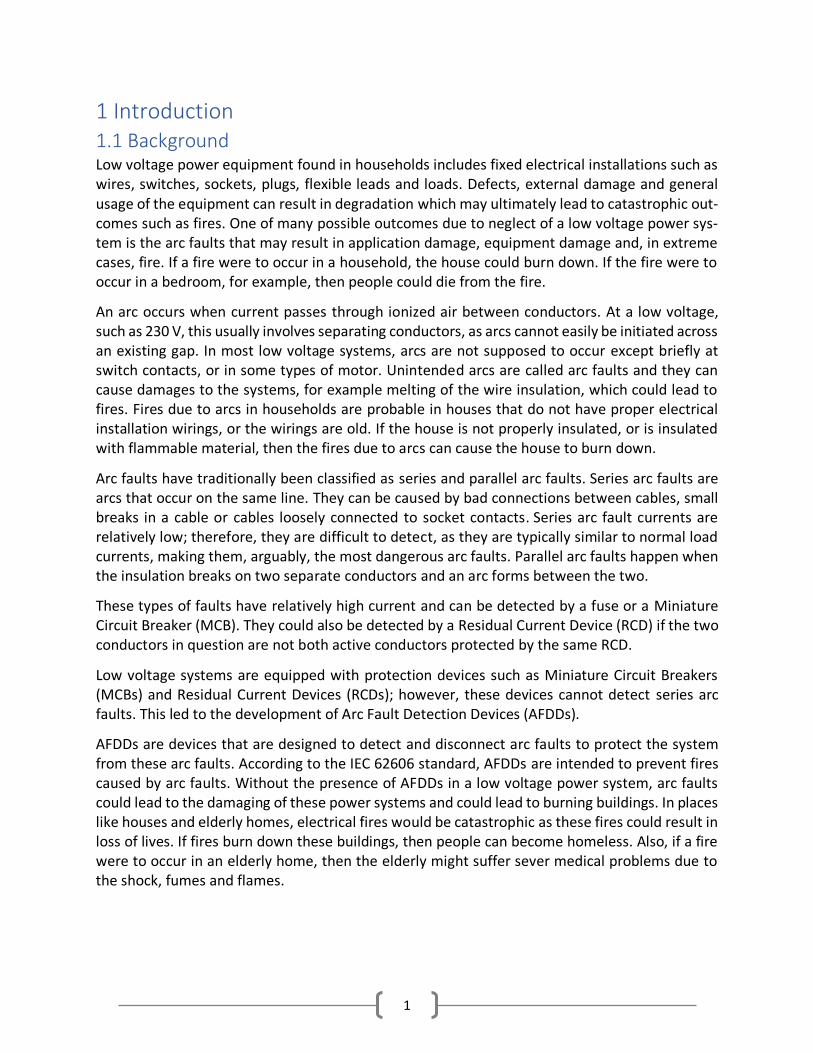
2.2.1 Series Arc Faults A series arc fault occurs when electricity jumps between two points on the same line [7]. The series arc current is limited to the load current as long as the load remains in series with it [8]. The figure below shows an occurrence of a series arc fault.
Figure 1: Series Arc Fault [9]
A series arc fault occurs, for example, when a wire is broken, as the figure above shows, or a contact is loose. Series arc faults are considered the most dangerous arc faults simply because they are difficult to detect [10]. Series arc faults cannot be detected by overcurrent protection devices or residual current devices; however, they may be detected by Arc Fault Detection De-vices (AFDDs).
4
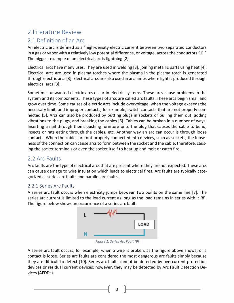
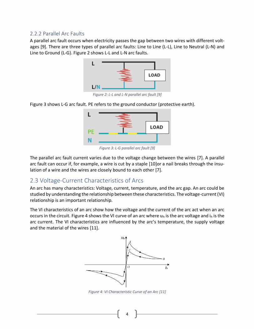
2.2.2 Parallel Arc Faults A parallel arc fault occurs when electricity passes the gap between two wires with different volt-ages [9]. There are three types of parallel arc faults: Line to Line (L-L), Line to Neutral (L-N) and Line to Ground (L-G). Figure 2 shows L-L and L-N arc faults.
Figure 2: L-L and L-N parallel arc fault [9]
Figure 3 shows L-G arc fault. PE refers to the ground conductor (protective earth).
Figure 3: L-G parallel arc fault [9]
The parallel arc fault current varies due to the voltage change between the wires [7]. A parallel arc fault can occur if, for example, a wire is cut by a staple [10]or a nail breaks through the insu-lation of a wire and the wires are closely bound to each other [7].
2.3 Voltage-Current Characteristics of Arcs An arc has many characteristics: Voltage, current, temperature, and the arc gap. An arc could be studied by understanding the relationship between these characteristics. The voltage-current (VI) relationship is an important relationship.
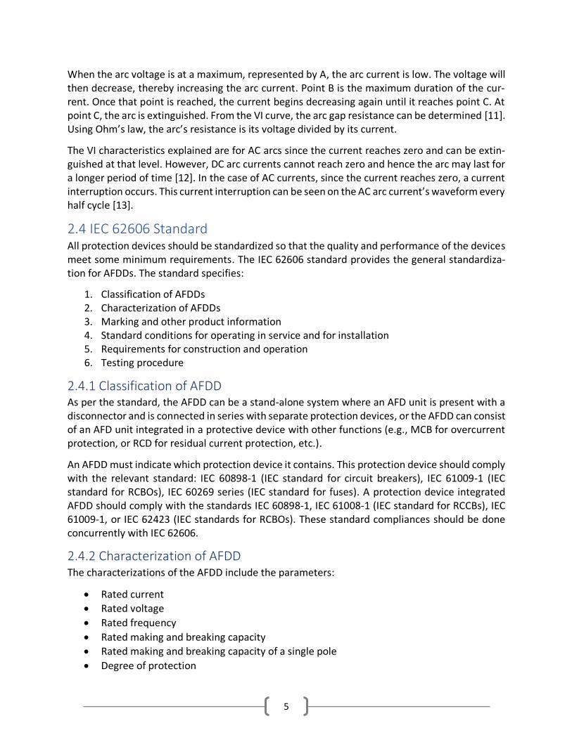
The VI characteristics of an arc show how the voltage and the current of the arc act when an arc occurs in the circuit. Figure 4 shows the VI curve of an arc where uh is the arc voltage and ih is the arc current. The VI characteristics are influenced by the arc’s temperature, the supply voltage and the material of the wires [11].
Figure 4: VI Characteristic Curve of an Arc [11]
5
When the arc voltage is at a maximum, represented by A, the arc current is low. The voltage will then decrease, thereby increasing the arc current. Point B is the maximum duration of the cur-rent. Once that point is reached, the current begins decreasing again until it reaches point C. At point C, the arc is extinguished. From the VI curve, the arc gap resistance can be determined [11]. Using Ohm’s law, the arc’s resistance is its voltage divided by its current.
The VI characteristics explained are for AC arcs since the current reaches zero and can be extin-guished at that level. However, DC arc currents cannot reach zero and hence the arc may last for a longer period of time [12]. In the case of AC currents, since the current reaches zero, a current interruption occurs. This current interruption can be seen on the AC arc current’s waveform every half cycle [13].
2.4 IEC 62606 Standard All protection devices should be standardized so that the quality and performance of the devices meet some minimum requirements. The IEC 62606 standard provides the general standardiza-tion for AFDDs. The standard specifies:
1. Classification of AFDDs 2. Characterization of AFDDs 3. Marking and other product information 4. Standard conditions for operating in service and for installation 5. Requirements for construction and operation 6. Testing procedure
2.4.1 Classification of AFDD As per the standard, the AFDD can be a stand-alone system where an AFD unit is present with a disconnector and is connected in series with separate protection devices, or the AFDD can consist of an AFD unit integrated in a protective device with other functions (e.g., MCB for overcurrent protection, or RCD for residual current protection, etc.).
An AFDD must indicate which protection device it contains. This protection device should comply with the relevant standard: IEC 60898-1 (IEC standard for circuit breakers), IEC 61009-1 (IEC standard for RCBOs), IEC 60269 series (IEC standard for fuses). A protection device integrated AFDD should comply with the standards IEC 60898-1, IEC 61008-1 (IEC standard for RCCBs), IEC 61009-1, or IEC 62423 (IEC standards for RCBOs). These standard compliances should be done concurrently with IEC 62606.
2.4.2 Characterization of AFDD The characterizations of the AFDD include the parameters:
• Rated current
• Rated voltage
• Rated frequency
• Rated making and breaking capacity
• Rated making and breaking capacity of a single pole
• Degree of protection
6
• Rated conditional short circuit
• Rated conditional short circuit current on one pole
• Method of connection
An AFDD should ensure the detection of earth arc faults, parallel arc faults and series arc faults in order to mitigate fires.
2.4.3 Marking and Other Product Information The markings of the above parameters should be mentioned on the product with some visibility when the product is installed. Apart from the above parameters a wiring diagram and a standard reference should also be included. All information should be present in a leaflet apart from men-tioning it on the AFDD.
2.4.4 Standard Conditions for Operating in Service and for Installation Standard conditions for operating in service and installation frames the general tolerances of the developed AFDD, that includes the temperature of operation (-5 °C to 40 °C), altitude of less than 2000 m, relative humidity at 40 °C at 50%, frequency tolerance (±5%), sinusoidal wave distortion (5%) etc. Further, the devices are built for pollution degree 2, where it specifies that only non-conductive pollution occur, and occasionally a temporary conductivity is expected due to con-densation.
2.4.5 Requirements for Construction and Operation Apart from complying with the above requirements, the requirements of the construction and operation section of the standard considers the AFDD switching mechanism, creepage and clear-ance distances in pollution degree 2 environment with regard to specific voltage ratings, current carrying parts and connections and their ability to withstand the mechanical and electrical stresses, protection against electric shocks and the dielectric properties and isolation capability of the device.
2.4.6 Breaking Capacity The standard states preferred values for the rated voltage and current. The preferred rated volt-ages are 120 V and 230 V. The preferred rated currents are 6 A to 63 A. The minimum arcing current is 2.5 A and the maximum arcing current is 63 A. In a recent update to the standard (2019), the typical line-voltages are also included so that AFDDs can be made for example 400 V in a 230 V three-phase system or 240 V in a 120 V split-phase system.
IEC 62606 denotes the breaking times for AFDDs in Low voltage systems. Table 1 shows the break-ing time for different currents at two voltages 230 V and 120 V. This table is taken from the IEC 62606 standard.
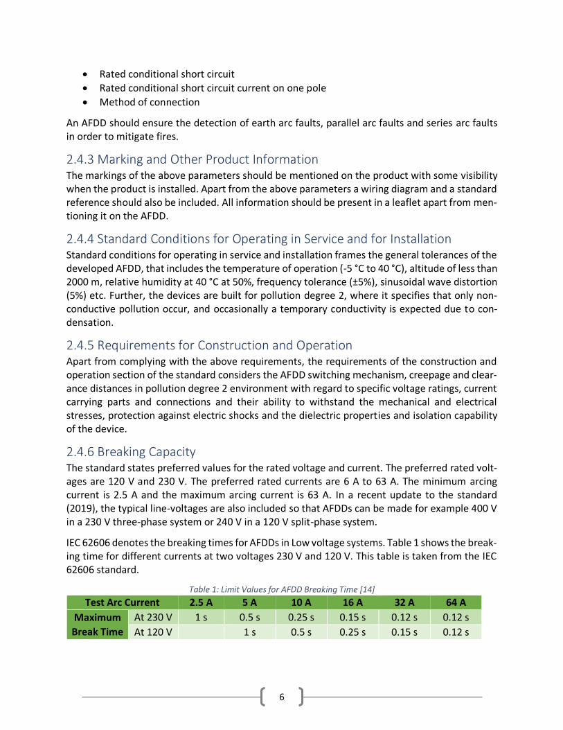
Table 1: Limit Values for AFDD Breaking Time [14]
Test Arc Current 2.5 A 5 A 10 A 16 A 32 A 64 A
Maximum
Break Time
At 230 V 1 s 0.5 s 0.25 s 0.15 s 0.12 s 0.12 s
At 120 V 1 s 0.5 s 0.25 s 0.15 s 0.12 s

7
2.4.7 Testing Procedure There are a variety of tests to be conducted in order for the AFDD to be IEC standard compliant. The complete list of tests is provided in the IEC 62606 standard [14]. Few of the tests that are of concern are discussed below:
2.4.7.1 Testing of the Reliability of Screws, Current-Carrying Parts and Connections The test includes the tightening and loosening of screws and nuts 5 times in general and if the screws engage with a tread of insulating material the test has to be conducted 10 times. The loosing and tightening of the parts are conducted with a specified torque for the part dimensions.
2.4.7.2 Reliability of Terminals for External Conductors The terminals are fitted with copper conductors either stranded or solid, whichever provides the worst-case scenario. The conductor cross sectional area range is decided on the device current rating. The terminals should be able to host stranded or solid conductors and the test should be done with the conductors of smallest and largest cross sections of the range.
The conductor is inserted into a new terminal for the minimum distance prescribed or, where no distance is prescribed, until it just projects from the far side, and in the position most likely to assist the wire to escape. Once inserted the screws which hold the conductor are tightened to two thirds of the specified torque for the screw.
During the test, the conductors are subjected to a pull with a specific force dependent upon the cross section of the wires. The pulling of each conductor is subjected to 1 minute and the appli-cation of force is done without jerks. The conductor should not visibly move and no shall show no undue damage or severed wires during or post-test.
2.4.7.3 Operation in Case of Series Arc Faults The AFDD should be able to detect arc faults and mitigate their effects by opening the circuit under series fault conditions within the time periods given in table 1. The standard test to check the validity of the AFDDs performance under series arc faults is as follows: A new AFDD should be mounted to a 20 mm plywood board and connected with either single stranded or multi stranded copper wires of which the diameter is determined by the maximum system current. The circuit with which the series arc fault test is conducted is depicted in figure 5. All experiments are run at the rated voltage of the AFDD. The test considers the AFDD break time at each arc current level and the measured value should not exceed table 1.
The system is depicted in figure 5. The test setup consists of four switches and a carbonized cable
specimen. The carbonized cable specimen is obtained by tying two conductors with a cross sec-
tion of 1.5 mm2 and providing a 30 mA short circuit current with an open circuit voltage of 7 kV,
which is energized for 10 seconds. Further, a 300 mA short current is also provided to the sample
at a minimum voltage of 2 kV, which is energized for 1 minute or until the smoking seizes to exist.
8
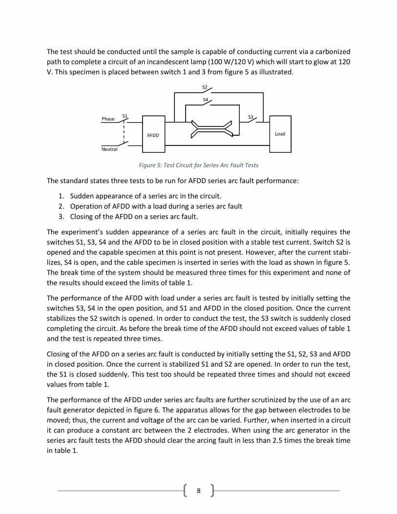
The test should be conducted until the sample is capable of conducting current via a carbonized
path to complete a circuit of an incandescent lamp (100 W/120 V) which will start to glow at 120
V. This specimen is placed between switch 1 and 3 from figure 5 as illustrated.
The standard states three tests to be run for AFDD series arc fault performance:
1. Sudden appearance of a series arc in the circuit.
2. Operation of AFDD with a load during a series arc fault
3. Closing of the AFDD on a series arc fault.
The experiment’s sudden appearance of a series arc fault in the circuit, initially requires the
switches S1, S3, S4 and the AFDD to be in closed position with a stable test current. Switch S2 is
opened and the capable specimen at this point is not present. However, after the current stabi-
lizes, S4 is open, and the cable specimen is inserted in series with the load as shown in figure 5.
The break time of the system should be measured three times for this experiment and none of
the results should exceed the limits of table 1.
The performance of the AFDD with load under a series arc fault is tested by initially setting the
switches S3, S4 in the open position, and S1 and AFDD in the closed position. Once the current
stabilizes the S2 switch is opened. In order to conduct the test, the S3 switch is suddenly closed
completing the circuit. As before the break time of the AFDD should not exceed values of table 1
and the test is repeated three times.
Closing of the AFDD on a series arc fault is conducted by initially setting the S1, S2, S3 and AFDD
in closed position. Once the current is stabilized S1 and S2 are opened. In order to run the test,
the S1 is closed suddenly. This test too should be repeated three times and should not exceed
values from table 1.
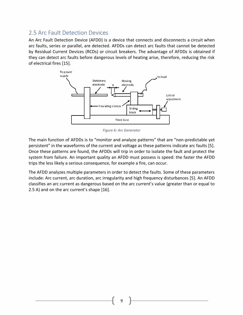
The performance of the AFDD under series arc faults are further scrutinized by the use of an arc
fault generator depicted in figure 6. The apparatus allows for the gap between electrodes to be
moved; thus, the current and voltage of the arc can be varied. Further, when inserted in a circuit
it can produce a constant arc between the 2 electrodes. When using the arc generator in the
series arc fault tests the AFDD should clear the arcing fault in less than 2.5 times the break time
in table 1.
Figure 5: Test Circuit for Series Arc Fault Tests
9
2.5 Arc Fault Detection Devices An Arc Fault Detection Device (AFDD) is a device that connects and disconnects a circuit when arc faults, series or parallel, are detected. AFDDs can detect arc faults that cannot be detected by Residual Current Devices (RCDs) or circuit breakers. The advantage of AFDDs is obtained if they can detect arc faults before dangerous levels of heating arise, therefore, reducing the risk of electrical fires [15].
The main function of AFDDs is to “monitor and analyze patterns” that are “non-predictable yet persistent” in the waveforms of the current and voltage as these patterns indicate arc faults [5]. Once these patterns are found, the AFDDs will trip in order to isolate the fault and protect the system from failure. An important quality an AFDD must possess is speed: the faster the AFDD trips the less likely a serious consequence, for example a fire, can occur.
The AFDD analyzes multiple parameters in order to detect the faults. Some of these parameters include: Arc current, arc duration, arc irregularity and high frequency disturbances [5]. An AFDD classifies an arc current as dangerous based on the arc current’s value (greater than or equal to 2.5 A) and on the arc current’s shape [16].
Figure 6: Arc Generator
10
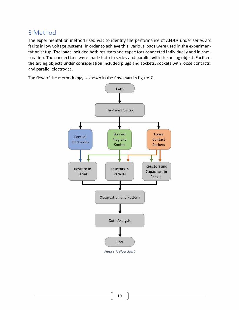
3 Method The experimentation method used was to identify the performance of AFDDs under series arc faults in low voltage systems. In order to achieve this, various loads were used in the experimen-tation setup. The loads included both resistors and capacitors connected individually and in com-bination. The connections were made both in series and parallel with the arcing object. Further, the arcing objects under consideration included plugs and sockets, sockets with loose contacts, and parallel electrodes.
The flow of the methodology is shown in the flowchart in figure 7.
Figure 7: Flowchart

11
3.1 Hardware Setup General hardware setup includes a power supply (230 V), AFDDs, data acquisition and parameter measuring devices, arcing objects, and the loads. The circuit diagram is shown in figure 8.
3.1.1 AFDDs The AFDD brands used in these experiments were Eaton, Siemens, Schneider, and Hager. The
parameters for the AFDDs used in these experiments are summarized in the table 2.
Table 2: AFDD Parameters
All the AFDDs listed in Table 2 are in accordance with the IEC 62606 standard and include MCB
functions. The rated current was chosen to be 13 A if available, else the nearest. This rating in
the range of 10 A to 16 A is typical in the final circuits found in homes in Sweden. Each AFDD is
from a different manufacturer and has different specs. The following subsections include the in-
formation about each AFDD as a reference – to understand how the AFDD is supposed to work
based on the manufacturers’ descriptions.
AFDD Eaton Siemens Schneider Hager
Rated Voltage (V) 230 230 230 230
Rated Current (A) 13 13 16 13
Tripping Time as
per Standard Yes Yes Yes Yes
Figure 8: Circuit Diagram

12
3.1.1.1 Eaton AFDD Eaton’s AFDD+, AFDD-13/2/C/003-Li/A, (shown in figure 9) combines two types of protections from RCBOs (Residual Current operated circuit Breaker with Overcurrent protection), specifically short circuit protection and residual current protection. The protection provided by RCBOs are combined with AFDDs to create the AFDD+. The AFDD+ is a sensitive fault current detection de-vice that “uses embedded processing and smart evaluation of current signals” to detect danger-ous arc faults in the system [17].
The AFDD+ protects against arc faults, earth fault currents and short circuit and overcurrent. The AFDD+ also provides enhanced fire protection as well as shock prevention [17]. The AFDD+ fol-lows the IEC 62606 standard by protecting against fires and disconnecting the system when a dangerous series or parallel arc is detected in the system. Eaton’s AFDD+ detects an arc by looking at its current. Specifically, the current’s high frequency noise and if the current is approaching the voltage’s zero crossing (i.e., point C in Figure 4).
3.1.1.2 Siemens AFDD Siemens is the first to create a fire preventing AFDD in compliance with the IEC 62606 standard [18]. This AFDD is known as the 5SV6 AFDD – 5SV6 016-7KK13. It is the smallest AFDD and is the first AFDD to integrate an MCB (Miniature Circuit Breaker) [18]. The Siemens 5SV6 AFDD is shown in figure 10.
Figure 10: Siemens 5SV6 AFDD [18]
Figure 9: Eaton AFDD+ [17]

13
The 5SV6 detects arcs by measuring the high frequency of the arc’s current and voltage in terms of intensity, duration, and gaps [18]. The detection of the arc’s current and voltage is done through an “intelligent software” that will analyze the signals and disconnect the AFDD in the presence of unusual readings. The disconnection is done in accordance with the IEC62606 stand-ard – maximum one second. The 5SV6 AFDD distinguishes between harmless and dangerous arcs. Therefore, the 5SV6 AFDD prevents fires from occurring [18].
3.1.1.3 Schneider AFDD Schneider’s A9FDB7616 (shown in figure 11) is an arc fault detection circuit breaker [19]. It is classified as a circuit breaker and follows the IEC standards for both AFDDs and Circuit Breakers, IEC 62606 and IEC 60898-1 respectively. The Schneider AFDD protects against fires dues to dan-gerous arcs and overvoltage.
3.1.1.4 Hager AFDD Hager’s ARC963D AFDD (shown in figure 12) combines two protection devices, the MCB and the earth fault circuit breaker [20]. The ARC963D AFDD is controlled by a microprocessor that detects arc faults and disconnects the AFDD when a dangerous arc is detected. The ARC963D AFDD pro-tects against both series and parallel arcs. The microprocessor inside the AFDD “continuously monitors 120 current and voltage parameters” [20]. The ARC963D AFDD follows the IEC 62606 standard.
Figure 11: Schneider A9FDB7616 AFDD [19]
Figure 12: Hager ARC963D AFDD [20]

14
3.1.2 Data Acquisition and Measuring Devices The parameters under consideration are voltage and current. Voltage was measured using the
high voltage differential probe shown in figure 13 (a). Current was measured using the clamp-on
current probe shown in figure 13 (b). The sample rate of each channel was 32 kHz. The data was
logged and recorded using a National Instrument Multifunction I/O Device (DAQ) and MATLAB.
The DAQ can be seen in figure 13 (c).
(c)
(b) (a)
Figure 13: (a) Differential Voltage Probe (b) Current Probe (c) National Instrument Multi-function I/O Device (DAQ)

15
3.2 Arcing Objects Three arcing objects were used in this experimental setup: Parallel electrodes, burned plug and socket, and loose contacts in the connections to a selection of sockets.
3.2.1 Parallel Electrodes Various sets of electrodes were used in these experiments all of which consist of different types of wires:
• Single strand copper
• Multistrand copper
• Combination of multistrand and single strand
• Enameled copper
These wires were used as electrodes (shown in figure 14 (a)) and the arcing was produced be-tween these two parallel electrodes as shown in figure 14 (b) by manipulating the electrode dis-tance with the aid of an insulated rod.
3.2.2 Burned Plug and Socket The burned plug and socket (shown in figure 15) arcing objects are Swedish standard ‘Schuko’ – type obtained from an electrical installation in which damage had occurred naturally during long-term operation of a washing machine presumably with some initial defect in a connection which led to the carbonization of the objects.
(a) (b)
Figure 14: (a) Parallel Electrodes Test (b) Arc Forming Between Electrodes
(a) (b)
Figure 15: (a) Burned Socket (b) Burned Plug

16
The experiment was conducted by inserting the plug into the socket, moving the plug while in-serted and removing the plug from the socket. The relevance of these movements is that vibra-tions could happen when a socket is by a load such as a washing machine. The damage already sustained by the plug and socket has left the contacts dirty and loose, and often able to sustain a compact arc at the contact point.
3.2.3 Loose Contact Sockets The loose contact socket experiment (shown in figure 16) was conducted only at the socket ter-minals where the fixed wiring would connect, i.e., not the contact with the plug. As will be seen in the discussion section, there are some cases where arcs were produced without any vibrations and can continue for a long enough time to cause a fire. However, in order to obtain arcing and change of the surfaces in the short available time, the wires in the socket terminals were, in most cases, manipulated to rub the surfaces, which has some relevance to a real-life case, for example if the loose connection is placed behind a washing machine and the vibrations from the wash-ing machine causes the wire to move in the loosely connected terminals. The loose contacts caused sparks, arcs, and, in some cases, fire.
Multiple brands of sockets were experimented upon during this test. These include: MK (contam-inated and new), Contactum, Crabtree, Alfanar and Schneider. The sockets used are all UK stand-ard sockets.
3.3 Loads There were multiple loads used in these experiments, resistive and capacitive loads. The resistive loads include a 2000 W heater and six incandescent lightbulbs. The capacitive loads include a MacBook charger connected to a MacBook laptop and an LCD display. These types of loads were chosen as they are commonly found in low voltage systems in domestic situations. The loads, shown in figure 8, were used in the experiment in multiple ways:
• One resistive load (2000 W heater)
• Two resistive loads in parallel
• Two resistive and two capacitive loads in parallel
Figure 16: Loose Contact Socket Test

17
4 Results A variety of experiments were run to test the AFDDs’ performances. The tests are categorized as parallel electrodes, burned plug and socket, and loose contact sockets.
4.1 Parallel Electrodes The parallel electrodes tests consist of enameled copper wires, single stranded copper wires, multi-stranded copper wires, and a combination of multi-stranded and single stranded copper wires. This was a preliminary test conducted in order to better understand arcs and AFDD tripping methodology. Thus, the number of tests and the duration of the tests are not standardized. Fur-thermore, the load application is limited to a single 2000 W heater in series with the system.
4.1.1 Enameled Copper Wires The enameled copper wires tests were done by scraping off the enamel from the copper wires so that pure copper was exposed. This was due to the observation made during preliminary tests where the enamel acted as insulation, thus preventing the wires to act as electrodes. It was ob-served that while the enamel acts as an insulation, when exposed to heat from arcs, the enamel catches fire.
With this test, the Eaton AFDD tripped instantly. As soon as an arc was formed, even though it had not yet caused any, the AFDD tripped. The Siemens AFDD performed the same as the Eaton AFDD but was slightly slower in reaction compared to the Eaton AFDD. The Schneider AFDD al-lowed the arc to continue for a few moments before it tripped. This caused the arc to form a fire between the wires before the AFDD tripped. The Hager AFDD, on the other hand, had a very slow reaction time to the arc faults, to the point that fires formed due to arcs. There were some in-stances where the fire formed and the AFDD did not trip. The speed of the tripping, from fastest to slowest, was Eaton, Siemens, Schneider and then Hager.
4.1.2 Single Stranded Copper Wires Two pure copper wires were used as electrodes in these tests. When it came to the single stranded copper wires, the Eaton AFDD did not always trip. There were many instances where the untripped arcs caused fires and the Eaton AFDD did not prevent these fires. However, the Eaton AFDD did trip at times.
The Siemen’s AFDD also had instances of not tripping when the arc occurred. It rarely tripped with this test. However, there were instances where a fire occurred, and the Siemens AFDD did not trip and extinguish the fire.
The Schneider and Hager AFDDs performed well in this test. Both AFDDs tripped when an arc fault was detected; therefore, fires did not occur with these AFDDS.
4.1.3 Multi-Stranded Copper Wires Multi-stranded copper wires had a gauge of 2.5 mm with each wire consisting of seven strands. The arcs were difficult to perform for this test since there are multiple strands and multiple arcs can occur. However, the Eaton, Schneider and Hager AFDDs performed well as they all tripped

18
every time arcs were detected. The Siemen’s AFDD did not trip at all with this test. Multiple arcs formed and some of those arcs created fires and the AFDD never tripped.
4.1.4 Multi-Stranded Vs. Single Stranded Copper Wires In these tests, one electrode was a 2.5 mm, seven stranded wire (i.e., multi-stranded wire) and the other electrode was a single stranded pure copper wire. The Eaton and Hager AFDDs did not trip when arcs were detected. These arcs produced fires the AFDDs did not trip. The Siemens AFDD did not trip at all; however, no instances of fires were present. The Schneider AFDD tripped with every arc detected. The Schneider AFDD also prevented these arcs from producing fires.
4.2 Burned Plug and Socket The tests were conducted in two ways:
• Two resistive loads in parallel
• Two resistive and two capacitive loads in parallel
The tests were standardized in terms of test duration and number of tests. The time duration for each test was five minutes unless the AFDD was tripped. In which case, that concluded the test. The number of tests for each AFDD was limited to six tests.
4.2.1 Resistive Loads in Parallel All AFDDs managed to trip without any fire incidents, which can be seen in table 3. The duration of the tests was very small considering that the AFDDs tripped as soon as an arc was present.
Table 3: Burned Plug and Socket – Two Resistors in Parallel
AFDD Eaton Siemens Schneider Hager
Number of Tests 6 6 6 6
Number of Trips 6 6 6 6
Instances of Fire - - - -
Instances of Fire and No Trip - - - -
4.2.2 Resistive and Capacitive Loads in Parallel Table 4 shows that the Eaton and Siemens AFDDs managed to trip in all tests without instances of fire. The Hager AFDD had three instances of fires. In two of those cases, the fires did not cause the AFDD to trip, however, the AFDD tripped afterwards when an arc was produced during the test timeframe. In one of those instances, the AFDD did not trip. The Schneider AFDD was not tested due to the degradation of the test sample while running the standardized tests for Hager.
Table 4: Burned Plug and Socket – Resistors and Capacitors
AFDD Eaton Siemens Schneider Hager
Number of Tests 6 6 N/A 6
Number of Trips 6 6 N/A 5
Instances of Fire - - N/A 3
Instances of Fire and No Trip - - N/A 3
19
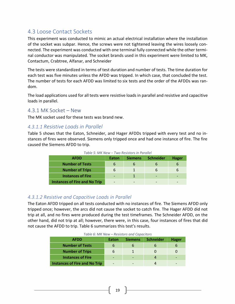
4.3 Loose Contact Sockets This experiment was conducted to mimic an actual electrical installation where the installation of the socket was subpar. Hence, the screws were not tightened leaving the wires loosely con-nected. The experiment was conducted with one terminal fully connected while the other termi-nal conductor was manipulated. The socket brands used in this experiment were limited to MK, Contactum, Crabtree, Alfanar, and Schneider
The tests were standardized in terms of test duration and number of tests. The time duration for each test was five minutes unless the AFDD was tripped. In which case, that concluded the test. The number of tests for each AFDD was limited to six tests and the order of the AFDDs was ran-dom.
The load applications used for all tests were resistive loads in parallel and resistive and capacitive loads in parallel.
4.3.1 MK Socket – New The MK socket used for these tests was brand new.
4.3.1.1 Resistive Loads in Parallel Table 5 shows that the Eaton, Schneider, and Hager AFDDs tripped with every test and no in-stances of fires were observed. Siemens only tripped once and had one instance of fire. The fire caused the Siemens AFDD to trip.
Table 5: MK New – Two Resistors in Parallel
AFDD Eaton Siemens Schneider Hager
Number of Tests 6 6 6 6
Number of Trips 6 1 6 6
Instances of Fire - 1 - -
Instances of Fire and No Trip - - - -
4.3.1.2 Resistive and Capacitive Loads in Parallel The Eaton AFDD tripped on all tests conducted with no instances of fire. The Siemens AFDD only tripped once; however, the arcs did not cause the socket to catch fire. The Hager AFDD did not trip at all, and no fires were produced during the test timeframes. The Schneider AFDD, on the other hand, did not trip at all; however, there were, in this case, four instances of fires that did not cause the AFDD to trip. Table 6 summarizes this test’s results.
Table 6: MK New – Resistors and Capacitors
AFDD Eaton Siemens Schneider Hager
Number of Tests 6 6 6 6
Number of Trips 6 1 0 0
Instances of Fire - - 4 -
Instances of Fire and No Trip - - 4 -
20
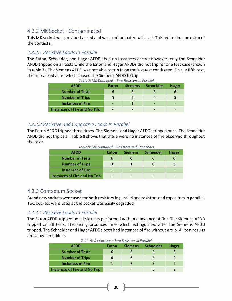
4.3.2 MK Socket - Contaminated This MK socket was previously used and was contaminated with salt. This led to the corrosion of the contacts.
4.3.2.1 Resistive Loads in Parallel The Eaton, Schneider, and Hager AFDDs had no instances of fire; however, only the Schneider AFDD tripped on all tests while the Eaton and Hager AFDDs did not trip for one test case (shown in table 7). The Siemens AFDD was not able to trip in on the last test conducted. On the fifth test, the arc caused a fire which caused the Siemens AFDD to trip.
Table 7: MK Damaged – Two Resistors in Parallel
AFDD Eaton Siemens Schneider Hager
Number of Tests 6 6 6 6
Number of Trips 5 5 6 5
Instances of Fire - 1 - -
Instances of Fire and No Trip - - - -
4.3.2.2 Resistive and Capacitive Loads in Parallel The Eaton AFDD tripped three times. The Siemens and Hager AFDDs tripped once. The Schneider AFDD did not trip at all. Table 8 shows that there were no instances of fire observed throughout the tests.
Table 8: MK Damaged – Resistors and Capacitors
AFDD Eaton Siemens Schneider Hager
Number of Tests 6 6 6 6
Number of Trips 3 1 0 1
Instances of Fire - - - -
Instances of Fire and No Trip - - - -
4.3.3 Contactum Socket Brand new sockets were used for both resistors in parallel and resistors and capacitors in parallel. Two sockets were used as the socket was easily degraded.
4.3.3.1 Resistive Loads in Parallel The Eaton AFDD tripped on all six tests performed with one instance of fire. The Siemens AFDD tripped on all tests. The arcing produced fires which extinguished after the Siemens AFDD tripped. The Schneider and Hager AFDDs both had instances of fire without a trip. All test results are shown in table 9.
Table 9: Contactum – Two Resistors in Parallel
AFDD Eaton Siemens Schneider Hager
Number of Tests 6 6 6 6
Number of Trips 6 6 3 2
Instances of Fire 1 6 3 2
Instances of Fire and No Trip - - 2 2

21
4.3.3.2 Resistive and Capacitive Loads in Parallel There were many instances of fire for all AFDDs (shown in table 10). The Eaton and Siemens AFDDs mitigated the fire by tripping. Whereas the Schneider and Hager AFDDs did not trip for all tests. The Hager AFDD only managed to complete three standardized tests before the socket disintegrated.
Table 10: Contactum – Resistors and Capacitors
AFDD Eaton Siemens Schneider Hager
Number of Tests 6 6 6 3
Number of Trips 6 6 0 0
Instances of Fire 5 6 5 3
Instances of Fire and No Trip - - 5 3
4.3.4 Crabtree Socket Brand new sockets were used for both resistors in parallel and resistors and capacitors in parallel. Two sockets were used as the socket was easily degraded.
4.3.4.1 Resistive Loads in Parallel Table 11 shows that the Eaton AFDD tripped in all tests without an instance of fire. The Siemens, Schneider, and Hager AFDDs tripped in all cases but there were instances of fires that did not cause the AFDD to trip at first. The charring on the wires would cause the socket to catch fire. In order to preserve the socket for testing all AFDDs, the wires needed to be cut and stripped so that uncontaminated wire could be used. These brand-new wires caused the AFDDs to trip.
Table 11: Crabtree – Two Resistors in Parallel
AFDD Eaton Siemens Schneider Hager
Number of Tests 6 6 6 6
Number of Trips 6 6 6 6
Instances of Fire - N/A N/A N/A
Instances of Fire and No Trip - N/A N/A N/A
4.3.4.2 Resistive and Capacitive Loads in Parallel The Eaton AFDD tripped in all tests; however, there was only one instance of fire that did not cause a trip (shown in table 12). The AFDD managed to trip on a different arc during the test timeframe. The Siemens AFDD had instances of fires in all cases and the AFDD tripped every time. The Schneider AFDD tripped only once without any instances of fires. The Hager AFDD did not trip at all, and no fires were observed.
Table 12: Crabtree – Resistors and Capacitors
AFDD Eaton Siemens Schneider Hager
Number of Tests 6 6 6 6
Number of Trips 6 6 1 0
Instances of Fire 1 6 - -
Instances of Fire and No Trip 1 - - -

22
4.3.5 Alfanar Socket Two brand new sockets were used for the experimentation. The first socket was tested under non-standardized conditions and was disintegrated – the socket caught fire and the insulation material around the contact bubbled. More on this can be found in section 5. The second socket was used for both resistors in parallel and resistors and capacitors in parallel.
4.3.5.1 Resistive Loads in Parallel All AFDDs tripped in all tests and no fires were produced. The results are summarized in table 13.
Table 13: Alfanar – Two Resistors in Parallel
AFDD Eaton Siemens Schneider Hager
Number of Tests 6 6 6 6
Number of Trips 6 6 6 6
Instances of Fire - - - -
Instances of Fire and No Trip - - - -
4.3.5.2 Resistive and Capacitive Loads in Parallel The Eaton AFDD tripped with all tests. The Siemens AFDD had one instance of no trip. The Schnei-der AFDD did not trip at all. The Hager AFDD only tripped once. It can be seen in table 14 that no instances of fire were observed for all tests.
Table 14: Alfanar – Resistors and Capacitors
AFDD Eaton Siemens Schneider Hager
Number of Tests 6 6 6 6
Number of Trips 6 5 0 1
Instances of Fire - - - -
Instances of Fire and No Trip - - - -
4.3.6 Schneider Socket A brand-new socket was used for two resistors and two capacitors in parallel.
4.3.6.1 Resistive and Capacitive Loads in Parallel Table 15 shows that the Eaton AFDD managed to trip three times out of the six tests conducted,
whereas the other AFDDs did not trip for any tests. No instances of fire were present.
Table 15: Schneider – Resistors and Capacitors
AFDD Eaton Siemens Schneider Hager
Number of Tests 6 6 6 6
Number of Trips 3 0 0 0
Instances of Fire - - - -
Instances of Fire and No Trip - - - -

23
5 Discussion This section will discuss the observations of the conducted experiments highlighted in the results section, specifically,
• Arcing object performance
• AFDD performance against the standard
• Fire hazards during experimentation
• Arc fault current waveforms
• Current harmonics of the system
5.1 Parallel Electrodes This experiment was conducted for the purpose of understanding series arcs. The parallel elec-trodes were placed inside a box as a safety measure and in order to move the electrodes an insulted rod was needed. It was assumed that the insulated rod would not affect the experi-mental setup and as most arcing objects, such as plugs and socket contacts, are encompassed in insulated material, this experimental method was assumed to be sound. However, it was evident through experimentation that arcs would cause temperature spikes that caused the insulated rod to melt onto the electrodes. The melted insulation on the electrodes caught fire when an arc was formed between the electrodes.
A variety of wires were used as electrodes for this experiment. Each wire reacted differently to arcs and the AFDD performance deviated across experiments. Due to this being a preliminary experiment, only observation-based analysis will be conducted.
5.1.1 Enameled Copper Wires As mentioned in the results section, enameled wires required scraping to expose the pure cop-per. Once exposed, the arcing could be produced with the manipulation of the insulated rod (shown in figure 17 (a)). Due to the arcing, the enamel tends to catch fire, as seen in figure 17 (b), under high temperatures.
(a) (b)
Figure 17: (a) Arcing Between Electrodes (b) Fire from Arcing Electrodes
24
The Eaton and Siemens AFDDs were highly capable of identifying these arcs and tripping, while the Hager and Schneider AFDDs did not so readily trip for this type of arc. This observation led to the hypothesis that the AFDDs have significantly different tripping algorithms, possibly analyzing different parameters to detect the arc fault.
Compared to other tests run in this experiment setup, the enameled copper electrodes caused relatively fast tripping. However, enameled copper is a simple example and can be found in some equipment, but it is not used in general low voltage electric installations. Therefore, it is not a good measure for a real low voltage power system.
5.1.2 Single Stranded Copper Wires Single strand copper wires used in this experiment had a gauge of 1.5 mm2 which is typical of a low voltage system installation. Therefore, this test setup us much more realistic than the enam-eled copper tests.
The electrode is made of pure copper; therefore, there is no inherent combustible material pre-sent such as enamel. This experiment lasted longer than the enameled experiment and the elec-trodes were subjected to multiple arcs. The arcs created caused charring on the electrodes and excessive heat, resulting in the melting of the insulating rod that was used to move the wires.
In cases where the AFDD was unable to trip, the arcs heated the rod. This resulted in the rod melting on the wires which eventually caused fires. AFDDs are designed to detect arc faults and protect the system from fires resulting from arcs, as per the IEC 62606 standard, and not from insulation materials catching fire. This explains the results in table 4, where the Eaton and Sie-mens AFDDs had instances of fire and no trips.
5.1.3 Multi-Stranded Copper Wires In these experiments, the wires used had a gauge of 2.5 mm2 with each wire consisting of seven strands. These are a common type of wires used in low voltage electrical installations at rated currents in the 13 A to 16 A range. Therefore, most of the experiments run will use this type of wire. The insulation is halogen free but contains some other flame retardant substance.
Electrodes with multiple strands have multiple connection points. This was found to be a problem for producing a sustained arc. Continued manipulation of these electrodes results in charring which eventually creates a sustained arc. Due to the individual strands having a small gauge and a single point of contact during connection, they are easily fused to the opposite electrode under arcing conditions, which prevents further arcing from occurring.
5.1.4 Multi-Stranded vs. Single Stranded Copper Wires The previous experiments showed that due to multiple strands in the wire, producing arcs was a problem. This method was used to try and minimize the fusing of electrodes by using two differ-ent electrodes that were previously used with these tests. The first electrode was the multi-stranded copper wire, and the second electrode was the single stranded copper wire. However, throughout the experiments, the two electrodes fused anyways. Therefore, due to the lack of sustained arcs, the AFDDs did not trip.
25
5.2 Burned Plug and Socket The standardization of the experiment was required as it was evident from previous experimen-tation that under longer time durations the arc object is more likely to produce more heat and fires due to insulation melting. The standardization for this experiment was set to five minutes per test or until a successful AFDD trip occurred. Each AFDD was subjected to six tests under specific loads.
The objective of the test was to see how an AFDD would perform with a test object that was already damaged. The terminals of the arcing object were already significantly charred before the experiment was conducted. This is a preferred test because, according to the IEC standard, the arcing object must be sufficiently charred before testing the AFDDs.
The first experiment included two parallel resistors as loads and the second experiment included two resistors and two capacitors in parallel as the loads. The reason for the use of capacitive loads was to see any difference in the AFDD performance due to the change in the system loads. Furthermore, the addition of capacitance in the system mimics the reality of a low voltage sys-tem.
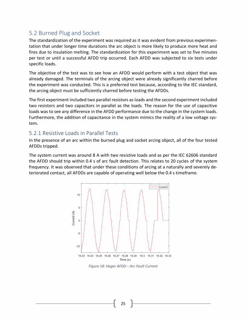
5.2.1 Resistive Loads in Parallel Tests In the presence of an arc within the burned plug and socket arcing object, all of the four tested AFDDs tripped.
The system current was around 8 A with two resistive loads and as per the IEC 62606 standard the AFDD should trip within 0.4 s of arc fault detection. This relates to 20 cycles of the system frequency. It was observed that under these conditions of arcing at a naturally and severely de-teriorated contact, all AFDDs are capable of operating well below the 0.4 s timeframe.
Figure 18: Hager AFDD – Arc Fault Current

26
As per figure 18, the fault arc occurs at 19.25 s and is sustained for 0.07 s at which the fault is detected and the AFDD trips. The shouldering seen in figure 18 is an example of how an arc ap-pears on an otherwise resistive current waveform.
Figure 19 illustrates the behavior of the fundamental frequency and the third harmonic of the system’s current for the same arc fault as in figure 18. As shown from the figure and all test re-sults, there should be evidence of third harmonics of the arc current for a trip to occur. For in-stances with third harmonics and a fundamental frequency current below 15% of the system current, the AFDD will not trip for most cases. It is evident from the results that for instances with a trip and a fundamental frequency current of below 15% that the AFDD’s tripping algo-rithm is taking other parameters into consideration.
5.2.2 Resistive and Capacitive Loads in Parallel Tests After the addition of two capacitive loads in parallel, the Eaton and Siemens AFDDs’ perfor-mances did not change, as seen in tables 7 and 8. The Hager AFDD, on the other hand, had mul-tiple instances of fire with no trip conditions. This caused the arcing object to deteriorate; there-fore, the standardized test could not be run for the Schneider AFDD.
There was only one arcing object and it changed irreversibly quickly; therefore, the arcing object could not be used for the Schnieder AFDD. In retrospect, it would have been preferable to have cycled through the AFDDs, doing one test case each then moving to the next AFDD. However, the results obtained here have no effect on the comparisons done. The degradation was not ex-pected to occur during the Hager AFDD test as the Eaton and Siemens AFDDs tripped without fire in all cases. Further, adequate time was provided to cool down the arcing object post each test.
5.3 Loose Contact Tests The results of the loose contact tests experiment are in line with the parallel electrodes experi-ment. The arcs produced due to the loose contacts cause excessive heat, making the surrounding
Figure 19: Hager AFDD Arc Fault Current Frequencies

27
insulation fold onto the socket contacts. The folding of the insulation provides material that may support fire. This depends on the insulation material, contact material and socket design.
5.3.1 AFDD Performance The results obtained for the loose contact tests show the performance of AFDDs under pure re-sistive loads (R loads) and a combination of resistive and capacitive loads (RC loads). Comparing the data between R and RC loads, there seems a clear trend that the AFDDs perform much better when there are no capacitive loads in the system. Due to the increased performance with purely resistive loads, fewer fires were caused by arc faults in those cases.
The Eaton AFDD was sensitive to all arcs with both load types. The high sensitivity of the Eaton AFDD also meant that it prevented fires. The Siemens AFDD performed well under R and RC loads equally. The Siemens AFDD tripped as soon as flames were observed, and the flames were extin-guished soon after the trip. The Schneider AFDD performed well with R loads; however, it did not trip at all with RC loads, as per the evidence obtained via experimentation. There were many instances of fire due to the lack of tripping from the Schneider AFDD under both R and RC loads. The Hager AFDD performed similarly to the Schneider AFDD under R and RC load conditions.
5.3.2 Socket Degradation The AFDDs detect potentially dangerous arcs; however, all arcs (dangerous or harmless) can cause socket degradation. The socket degradation will lead to insulation melting and may act as burn material causing fires.
The MK and Schneider sockets withstood all arcs with minimal damage. The insulation of these two sockets did not melt even under adverse conditions. In general, with these two sockets, sus-tained arcs were difficult to produce, and the arcs produced did not generate enough heat to cause the insulation around the contacts to melt and burn.
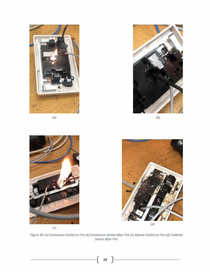
The Alfanar, Contactum and Crabtree sockets all caught fire as can be seen in figure 20. The fire was a result of continuous arcs without an AFDD trip causing excessive heat making the insulation material melt and fold into the contact. Once the insulation material catches fire, re-ignition of the fire is possible through any arc if and when the fire is extinguished.
28
(a) (b)
(c) (d)
Figure 20: (a) Contactum Socket on Fire (b) Contactum Socket After Fire (c) Alfanar Socket on Fire (d) Crabtree Socket After Fire
29
In a scenario where the socket is mounted to an application that is prone to vibrations, the con-tacts may vibrate, too, if the contacts are loosely connected. The wires may connect to contacts in such a way that small, internal fires ignite that are not detected by AFDDs which cause the insulation around the contacts to melt. This leads to increased socket degradation and eventual fires. Once degraded, the amount of vibration required to re-ignite the fire is minimal. This is a possible real-life scenario that could be improved by sensitive AFDDs, less combustible materials or contacts that reduce the chance of loose connections.
5.4 Instances of Fires
As was seen in the tables in the Results section, there were multiple instances of fires throughout the tests. Some of the fires were successfully extinguished by the tripping of the AFDDs and oth-ers were not. The socket that produced the most fires was the Contactum socket, and the figures shown below are all data collected while performing the loose contact test with the Contactum socket with the load being fully resistive (i.e., two resistors in parallel).
5.4.1 Instances of Fires with Trip In the case of the Contactum socket, there were two AFDDs that detected the fire and tripped. The tripping of the AFDDs protected the system from damages and the socket from degradation. These AFDDs are Eaton and Siemens.
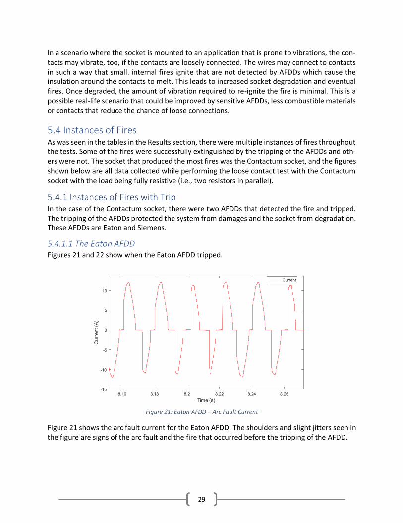
5.4.1.1 The Eaton AFDD Figures 21 and 22 show when the Eaton AFDD tripped.
Figure 21 shows the arc fault current for the Eaton AFDD. The shoulders and slight jitters seen in the figure are signs of the arc fault and the fire that occurred before the tripping of the AFDD.
Figure 21: Eaton AFDD – Arc Fault Current
30
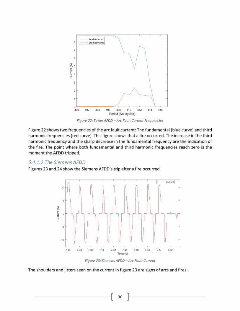
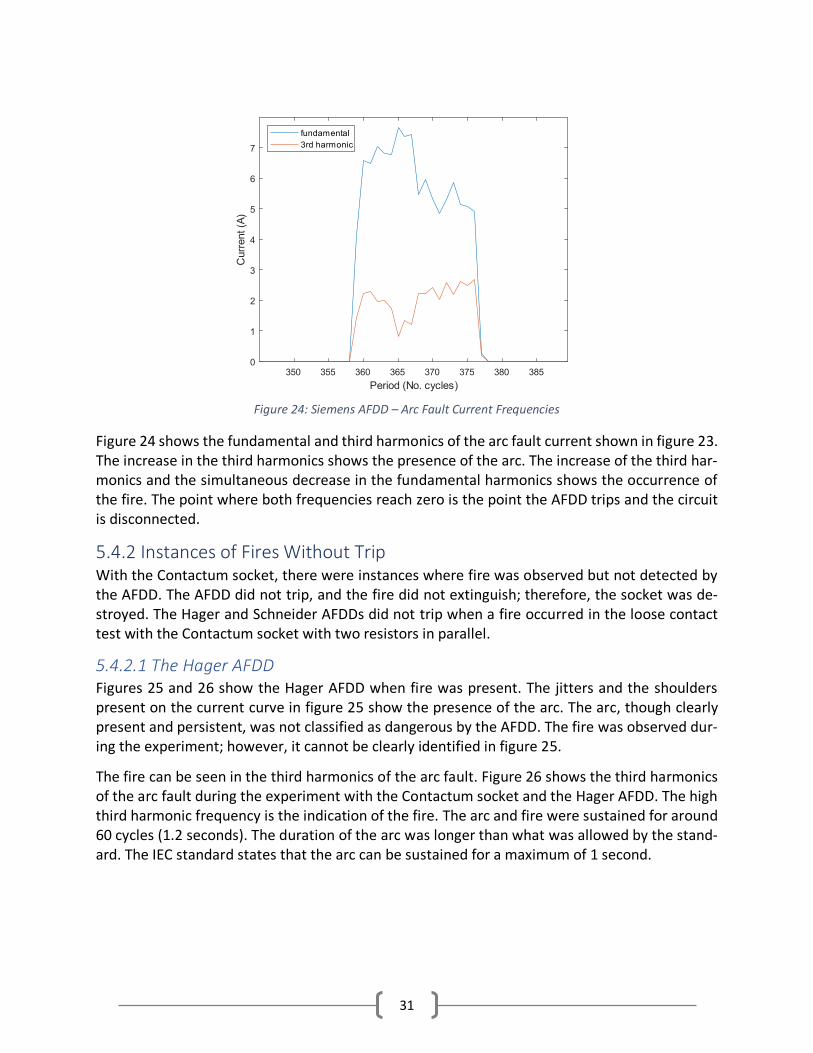
Figure 22 shows two frequencies of the arc fault current: The fundamental (blue curve) and third harmonic frequencies (red curve). This figure shows that a fire occurred. The increase in the third harmonic frequency and the sharp decrease in the fundamental frequency are the indication of the fire. The point where both fundamental and third harmonic frequencies reach zero is the moment the AFDD tripped.
5.4.1.2 The Siemens AFDD Figures 23 and 24 show the Siemens AFDD’s trip after a fire occurred.
The shoulders and jitters seen on the current in figure 23 are signs of arcs and fires.
Figure 22: Eaton AFDD – Arc Fault Current Frequencies
Figure 23: Siemens AFDD – Arc Fault Current
31
Figure 24 shows the fundamental and third harmonics of the arc fault current shown in figure 23. The increase in the third harmonics shows the presence of the arc. The increase of the third har-monics and the simultaneous decrease in the fundamental harmonics shows the occurrence of the fire. The point where both frequencies reach zero is the point the AFDD trips and the circuit is disconnected.
5.4.2 Instances of Fires Without Trip With the Contactum socket, there were instances where fire was observed but not detected by the AFDD. The AFDD did not trip, and the fire did not extinguish; therefore, the socket was de-stroyed. The Hager and Schneider AFDDs did not trip when a fire occurred in the loose contact test with the Contactum socket with two resistors in parallel.
5.4.2.1 The Hager AFDD Figures 25 and 26 show the Hager AFDD when fire was present. The jitters and the shoulders present on the current curve in figure 25 show the presence of the arc. The arc, though clearly present and persistent, was not classified as dangerous by the AFDD. The fire was observed dur-ing the experiment; however, it cannot be clearly identified in figure 25.
The fire can be seen in the third harmonics of the arc fault. Figure 26 shows the third harmonics of the arc fault during the experiment with the Contactum socket and the Hager AFDD. The high third harmonic frequency is the indication of the fire. The arc and fire were sustained for around 60 cycles (1.2 seconds). The duration of the arc was longer than what was allowed by the stand-ard. The IEC standard states that the arc can be sustained for a maximum of 1 second.
Figure 24: Siemens AFDD – Arc Fault Current Frequencies
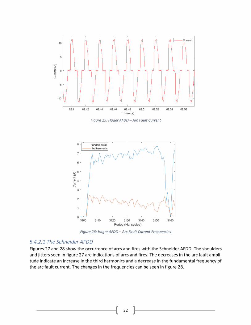
32
5.4.2.1 The Schneider AFDD Figures 27 and 28 show the occurrence of arcs and fires with the Schneider AFDD. The shoulders and jitters seen in figure 27 are indications of arcs and fires. The decreases in the arc fault ampli-tude indicate an increase in the third harmonics and a decrease in the fundamental frequency of the arc fault current. The changes in the frequencies can be seen in figure 28.
Figure 26: Hager AFDD – Arc Fault Current Frequencies
Figure 25: Hager AFDD – Arc Fault Current

33
The increase in the third harmonic frequency of the arc fault current and the significant decrease in the fundamental frequency, seen in figure 28, indicate the presence of the fire. When the ex-periment was conducted on the Contactum socket, the arcs produced created fires. The arc and the subsequent fire shown in figure 27 and 28 lasted for 407 cycles, equivalent to 8.14 seconds. The AFDD was supposed to detect the arc and trip in under one second. That was not the case in this experiment. The arc produced a fire that was large enough to degrade the socket. The fire produced is similar to the fire shown in figure 20 (a). A fire such as that could be catastrophic in an actual system.
Figure 28: Schneider AFDD – Arc Fault Current Frequencies
Figure 27: Schneider AFDD – Arc Fault Current

34
6 Conclusion The project was conducted to identify the performance of AFDDs under series arc fault conditions in low voltage systems and the objectives were met via experimentation and data analysis. The experiments run for the project used different arcing objects: Parallel electrodes, burned plug and socket, and loose contact sockets.
The parallel electrodes were used as a preliminary test to see how AFDDs react and have a better understanding of their general performances. A variety of electrodes were used in this regard, specifically enameled copper wires, single stranded copper wires and multi stranded copper wires. The experiment performed provided the hypothesis that the arcs, while generating heat, do not cause fire due to lack of burn material. However, when insulation breakdown occurs, the degraded insulation acts as the burn material, which causes fires.
The burned plug and socket arcing object was from a real-life, low voltage electrical failure. Hence, the sample was already charred and burned before experimental testing. This was a valid test object to check the performance of AFDDs as the IEC 62606 standard states that the arc object should be charred before AFDD testing. The performance of AFDDs differed under differ-ent load conditions. The performance of AFDDs in general were poor when the system included capacitive loads. Since general systems in present day usually contain capacitive loads, the AFDDs not performing as expected is of concern.
The loose contact socket arcing object experiment was done to mimic a real-life, subpar electrical installation. This experiment provided the results for the performance of AFDDs and the sockets under series arc fault conditions. The AFDDs in general do not perform well with capacitive loads, proving the previously made hypothesis.
Socket terminals that were tested under series arc fault conditions tended to heat up causing insulation degradation which is highly likely in reality as continuous series arc faults may occur that are not detected by the AFDDs to trip the system. Three out of the five UK standard sockets tested had insulation breakdowns and melting, resulting in fires without AFDD trips. The re-igni-tion of fire, if and when extinguished, requires small vibrations leading to simple arcs which are not detected by AFDDs; therefore, no trips occur.
It can be concluded that AFDDs could be useful for high-risk applications as back up protection because they are able to detect some series arcs and successfully trip the system, but they are not entirely reliable as there are cases in which series arc fault go undetected. False tripping (with just non-faulty loads) has not been tested in this work but is another important part of AFDD performance.
6.1 Recommendations Based on the experimentation results, the author recommends that a provision be made in the IEC standards to test the AFDDs under capacitive load conditions.
Under current circumstances, where series arcs are not detected by the AFDDS, the socket insu-lation should be able to withstand the series arcs until a sustained arc is created for the AFDDs to trip without causing a fire. This should also be included in standard testing for the socket.
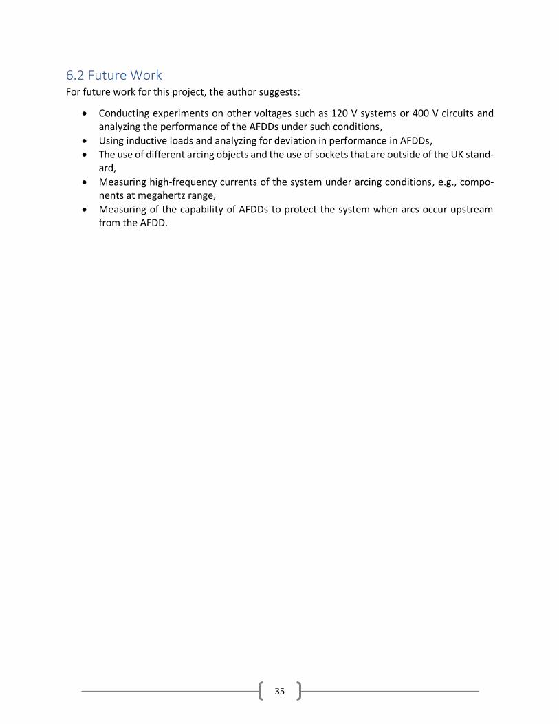
35
6.2 Future Work For future work for this project, the author suggests:
• Conducting experiments on other voltages such as 120 V systems or 400 V circuits and analyzing the performance of the AFDDs under such conditions,
• Using inductive loads and analyzing for deviation in performance in AFDDs,
• The use of different arcing objects and the use of sockets that are outside of the UK stand-ard,
• Measuring high-frequency currents of the system under arcing conditions, e.g., compo-nents at megahertz range,
• Measuring of the capability of AFDDs to protect the system when arcs occur upstream from the AFDD.
36
References [1] Encyclopædia Britannica, “Electric arc | physics | Britannica,” 2013.
https://www.britannica.com/science/electric-arc (accessed Jan. 19, 2021).
[2] Margaret Rouse, “What is electric arc? - Definition from WhatIs.com,” 2012. https://whatis.techtarget.com/definition/electric-arc (accessed Jan. 19, 2021).
[3] Ilana Steinhorn, “Electric Arcs | Encyclopedia.com,” 2021. https://www.encyclopedia.com/social-sciences-and-law/economics-business-and-labor/businesses-and-occupations/electric-arcs (accessed Jan. 19, 2021).
[4] “Weld | Definition of Weld by Merriam-Webster.” https://www.merriam-webster.com/dictionary/weld (accessed Jan. 19, 2021).
[5] J.-F. Rey, P. Dominique Socquet-Clerc, S. Tian, and Z. Belhaja, “How Arc Fault Detection Devices Minimize Electrical Fire Threats.”
[6] J.-M. Martel, “Series arc faults in low-voltage AC electrical installations,” 2017.
[7] Schneider Electric, “What is the difference between a parallel arc fault and a series arc fault? | Schneider Electric USA,” 2002. https://www.se.com/us/en/faqs/FA94231/ (accessed Jan. 19, 2021).
[8] Mike Holt, “Arc Fault Protection: What it’s all About,” 2002. https://www.mikeholt.com/mojonewsarchive/AFCI-HTML/HTML/Arc_Fault_Protection~20020124.htm (accessed Jan. 19, 2021).
[9] OEZ, “Arc fault detection devices - AFDD.” http://www.oez.com/news/arc-fault-detection-devices-afdd (accessed Jan. 19, 2021).
[10] S. Atlassi and N. Taylor, “A safety study of parallel arc faults with current- limiting sources,” KTH, 2018.
[11] Q. Lu, Z. Ye, Y. Zhang, T. Wang, and Z. Gao, “Analysis of the effects of arc volt–ampere characteristics on different loads and detection methods of series arc faults,” Energies, vol. 12, no. 2, 2019, doi: 10.3390/en12020323.
[12] T. Taufik, C. Aarstad, and A. Kean, “Arc fault characterization system for the low voltage DC arc fault circuit interrupter,” Proc. - 25th Int. Conf. Syst. Eng. ICSEng 2017, vol. 2017-Janua, pp. 106–112, 2017, doi: 10.1109/ICSEng.2017.36.
[13] E. Sritrai, S. Kittiratsatcha, and S. Polmai, “Low voltage series arc fault detection using rogowski coil,” ICEAST 2018 - 4th Int. Conf. Eng. Appl. Sci. Technol. Explor. Innov. Solut. Smart Soc., pp. 2018–2021, 2018, doi: 10.1109/ICEAST.2018.8434503.
[14] “IEC 62606 - General Requirements for Arc Fault Detection Devices,” 2013.
[15] Electrium, “How Arc Fault Detection Devices can benefit your next installation,” 2019. https://www.electrium.co.uk/news/how-arc-fault-detection-devices-can-benefit-your-next-installation (accessed Jan. 19, 2021).

37
[16] OEZ, “Modular devices,” 2019. [Online]. Available: www.oez.com.
[17] Eaton, “AFDD+ Range Brochure,” 2018.
[18] Siemens, “Arc fault detection devices | SENTRON protection devices | India.” https://new.siemens.com/in/en/products/energy/low-voltage/components/sentron-protection-devices/arc-fault-detection-devices.html (accessed Jan. 19, 2021).
[19] Schneider Electric, “Product environmental profile- Harmony 9001KQ,” 2012.
[20] Hager, “Arc detector AFDD: with dwarf switch or personal protection switch.” https://www.hager.se/loesningar/nyheter/energidistribution/ljusbaagsdetektor-afdd/157935.htm# (accessed Jan. 19, 2021).

TRITA-EECS-EX-2021:392
www.kth.se