Tests of Power Amplifiers for Single-Channel and Multi ... fileTD-SCDMA Power Amplifier Tests...
38
Subject to change – Roland Minihold 01/2007 – 1MA 103_0e Products: R&S ® SMU, R&S ® SMJ, R&S ® FSP, R&S ® FSU, R&S ® FSQ, R&S ® NRP, R&S ® NPR-Z11, R&S ® NRP-Z21 Tests of Power Amplifiers for Single-Channel and Multi-Channel TD-SCDMA Base Stations Application Note 1MA103 This Application Note describes how to perform measurements on power amplifiers for TD-SCDMA base stations to specification TS 25.142 using Rohde & Schwarz generators, power meters and signal/spectrum analyzers. The TD-SCDMA application firmware for Rohde & Schwarz generators and analyzers as well as their outstanding performance facilitate efficient and rapid measurements.
Transcript of Tests of Power Amplifiers for Single-Channel and Multi ... fileTD-SCDMA Power Amplifier Tests...

Subject to change – Roland Minihold 01/2007 – 1MA 103_0e
Products: R&S®SMU, R&S®SMJ, R&S®FSP, R&S®FSU, R&S®FSQ, R&S®NRP, R&S®NPR-Z11, R&S®NRP-Z21
Tests of Power Amplifiers for Single-Channel and Multi-Channel
TD-SCDMA Base Stations
Application Note 1MA103 This Application Note describes how to perform measurements on power amplifiers for TD-SCDMA base stations to specification TS 25.142 using Rohde & Schwarz generators, power meters and signal/spectrum analyzers. The TD-SCDMA application firmware for Rohde & Schwarz generators and analyzers as well as their outstanding performance facilitate efficient and rapid measurements.

TD-SCDMA Power Amplifier Tests
1Ma103_0e 2 Rohde & Schwarz
Contents 1 Overview ................................................................................................. 3 2 TD-SCDMA Signal Overview .................................................................. 3
TD-SCDMA signal structure (frames and timeslots)..................... 4 DwPTS and UpPTS ...................................................................... 5
3 Test Setups ............................................................................................. 6 4 Conventions for Instrument Settings ....................................................... 7
Rohde & Schwarz generators and analyzers................................ 7 Power Meter R&S®NRP................................................................ 7
5 Generating Test Signals.......................................................................... 8 Single-carrier signals.......................................................................... 9
Single-carrier signal with 8 code channels per slot active: ........... 9 Single-carrier signal with 10 code channels per slot active: ....... 11 Single-carrier signal with 1 code channel per slot active: ........... 13
Multi-carrier signals .......................................................................... 15 Generation of a phase-coherent two-carrier TD-SCDMA signal (R&S®SMU with two baseband units only):................................. 15 Generation of a phase-coherent four-carrier TD-SCDMA signal (ARB mode): ............................................................................... 16
6 TD-SCDMA Transmit Measurements ................................................... 18 Power meter measurements............................................................ 18
Output power (TS 25.142 chap. 6.2) and gain............................ 18 Input return loss/input VSWR ..................................................... 19 Power meter setup:..................................................................... 19
Measurements with spectrum analyzer/signal analyzer................... 20 Code domain power measurements: modulation accuracy (TS 25.142 chap. 6.8.1) and peak code domain error (TS 25.142 chap. 6.8.2) ................................................................................. 20 Gating of analyzer for spectrum measurements:........................ 23 Output power (TS 25.142 chap. 6.2):.......................................... 24 Quick power measurement in spectrum analysis mode using the time domain power function........................................................ 25 Crest factor measurement .......................................................... 26 Adjacent channel leakage power ACLR (TS 25.142 chap. 6.6.2.2).................................................................................................... 28 Multi-carrier ACLR (TS 25.142 chap. 6.6.2.2)............................. 29 Spectrum emission mask (TS 25.142 chap. 6.6.2.1).................. 31 Power versus Time (Transmit ON/OFF power TS 25.142 chap. 6.5) .................................................................................... 33
7 Glossary ................................................................................................ 36 8 References............................................................................................ 36 9 Additional Information ........................................................................... 36 10 Ordering information ............................................................................. 37

TD-SCDMA Power Amplifier Tests
1Ma103_0e 3 Rohde & Schwarz
1 Overview To perform measurements on power amplifiers for TD-SCDMA base stations compliant with TS25.142[10], the large dynamic range required in pulse mode operation is a special challenge for development and test engineers. This Application Note describes how to perform these measurements using Rohde & Schwarz generators, power meters and signal/spectrum analyzers. The TD-SCDMA application firmware for Rohde & Schwarz generators and analyzers as well as their outstanding performance facilitate efficient and rapid measurements.
2 TD-SCDMA Signal Overview Time Division Synchronous Code Division Multiple Access (TD-SCDMA) designates a mobile radio transmission method for 3G mobile communications developed by the China Wireless Telecommunication Standard group (CWTS, see http://www.cwts.org for details). The same frequency is used for transmissions in both directions with Time Domain Duplexing (TDD). Each resource (frequency, code and timeslot) can be used simultaneously by several base stations or user equipment, provided the scrambling codes differ. The standard is similar to the 3GPP TDD proposal, but with greater emphasis placed on GSM compatibility and with a chip rate limited to 1.28 Mcps. TD-SCDMA is included in the 3GPP Universal Terrestrial Radio Access (UTRA) as the UTRA-TDD option, called 1.28 Mcps TDD or Low Chip Rate (LCR) TDD. TD-SCDMA is a mobile radio standard in which available bandwidth is shared among subscribers according to frequency (FDMA), time (TDMA) and code (CDMA).
Fig. 1: Principle of TD-SCDMA channel access with TDMA in TDD mode
single frequency

TD-SCDMA Power Amplifier Tests
1Ma103_0e 4 Rohde & Schwarz
Fig. 2: Principle of TD-SCDMA code division multiple access
TD-SCDMA signal structure (frames and timeslots) The TD-SCDMA signal is organized in frames of 5 ms length. Each frame comprises seven traffic timeslots (TS0 to TS6, each 0.675 ms) and two special timeslots (DwPTS and UpPTS) for synchronization.
TS0 is always allocated to the downlink, TS1 to the uplink. The other timeslots are divided between the two directions of transmission. The switching point which separates the uplink slots from the downlink slots is variable.
Fig. 3: Structure of a TD-SCDMA frame
For testing base station power amplifiers, the downlink slots are relevant. According to TS 25.142 [10] – e.g. Table 6.2.A in chapter 6.2.4.1.2, the switching point is located between TS3 and TS4. TS4, 5 and 6 are to be activated on the signal generator.

TD-SCDMA Power Amplifier Tests
1Ma103_0e 5 Rohde & Schwarz
DwPTS and UpPTS In the downlink pilot timeslot (DwPTS), the base station sends one of 32 possible 64-chip SYNC codes.
Fig. 4: DwPTS structure
The user equipment synchronizes to the base station using the same synchronization code (SYNC code), which also defines the value range for the scrambling code and the basic midamble code.
The uplink pilot timeslot (UpPTS) is sent by the user equipment to initiate a call with the base station and is therefore not relevant when testing TD-SCDMA base station power amplifiers.
Fig. 5: UpPTS structure
See [1] – Chapter "Digital Standard TD-SCDMA: TD-SCDMA Signal Structure" for more detailed information.

TD-SCDMA Power Amplifier Tests
1Ma103_0e 6 Rohde & Schwarz
3 Test Setups The test setup shown in Fig. 6 is used for all the measurements described in this Application Note. An R&S®SMU or R&S®SMJ serves as a signal source and an R&S®FSU/FSQ or R&S®FSP carries out the signal analysis. An (optional) bi-directional coupler is used to couple out the forward and reflected signals at the input of the power amplifier under test.
To calculate the amplifier's VSWR, input power and reflected power are measured by sensor 1 and 2.
To measure the power amplifier's output power and gain (= (output power)/(input power)) with the maximum achievable accuracy, power sensor 3 is required. Although the absolute power measurement accuracy of an R&S®FSU or R&S®FSQ is excellent for a spectrum analyzer (0.3 dB absolute accuracy), the accuracy of a power meter, especially that of the R&S®NRP power meter, will always be better.
The marker 1 output (frame start) from the signal generator delivers the trigger signal to the analyzer and the power meter. All measurements can be carried out in sync with the TDMA frame.
The R&S®NRP-Z21 sensors can be used without the power meter base unit as standalone measuring instruments and connected directly via R&S®NRP-Z4 USB adapters to a controlling PC; the trigger signal must be fed to every power sensor via the BNC connectors of the R&S®NRP-Z4 USB adapters.
The analyzer's and signal generator's time bases are locked by feeding the generator's reference output signal to the analyzer's reference input.
Fig. 6: Proposed test setup with optional power sensors

TD-SCDMA Power Amplifier Tests
1Ma103_0e 7 Rohde & Schwarz
4 Conventions for Instrument Settings
Rohde & Schwarz generators and analyzers The following conventions of notation are used when referring to settings on Rohde & Schwarz generators and analyzers. Key strokes are in bold italics and softkey strokes in normal italics:
Convention Description Example
<Key> Press a key on the front panel FREQ
<Softkey> Press a softkey MARKER –>PEAK
<Key>:<Softkey1>:<… >:…
In a sequence of key strokes or softkey strokes, a colon is used as a separator
MARKER: MARKER –>PEAK
<nn unit> First enter the value using the numerical keypad, then complete the entry with the unit
12 kHz
<nn ENTER> First enter the value via the numerical keypad, then complete the entry with the Enter key.
TDS BS: SETTINGS: SCRAMBLING CODE 1: ENTER
(<Comment>) Comments are enclosed in round brackets.
(enter required frequency)
Table 1: Conventions of notation for settings on R&S generators and analyzers
Power Meter R&S®NRP The conventions are as above, with the important difference that numerical entries are made with softkeys and terminated with the Menu key. Values in square brackets are not settings to be made, but results or information for the user.
Example:
PRESET:PRESET FREQ:[A]:[50MHz] DEL/TRIG 1: 2.12:UNIT[GHz]: Menu
In the example, the UNIT softkey is used to toggle between the units "MHz" and "GHz".
TD-SCDMA Power Amplifier Tests
1Ma103_0e 8 Rohde & Schwarz
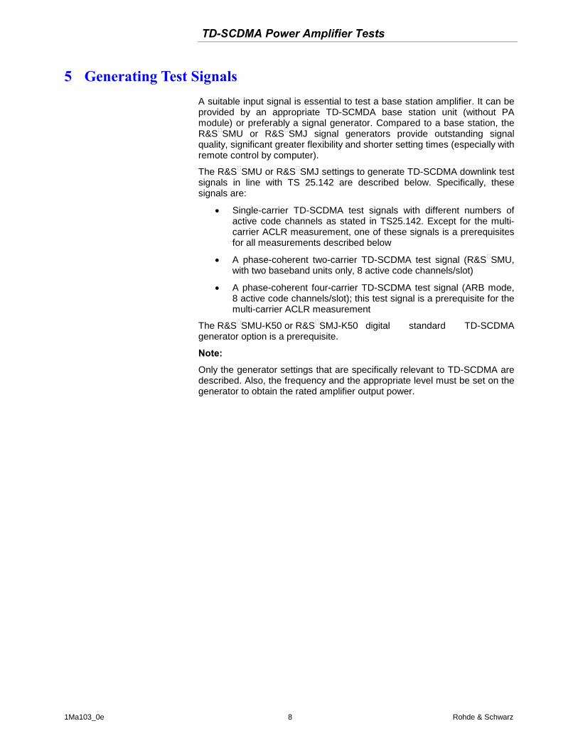
5 Generating Test Signals A suitable input signal is essential to test a base station amplifier. It can be provided by an appropriate TD-SCMDA base station unit (without PA module) or preferably a signal generator. Compared to a base station, the R&S®SMU or R&S®SMJ signal generators provide outstanding signal quality, significant greater flexibility and shorter setting times (especially with remote control by computer).
The R&S®SMU or R&S®SMJ settings to generate TD-SCDMA downlink test signals in line with TS 25.142 are described below. Specifically, these signals are:
Single-carrier TD-SCDMA test signals with different numbers of active code channels as stated in TS25.142. Except for the multi-carrier ACLR measurement, one of these signals is a prerequisites for all measurements described below
A phase-coherent two-carrier TD-SCDMA test signal (R&S®SMU, with two baseband units only, 8 active code channels/slot)
A phase-coherent four-carrier TD-SCDMA test signal (ARB mode, 8 active code channels/slot); this test signal is a prerequisite for the multi-carrier ACLR measurement
The R&S®SMU-K50 or R&S®SMJ-K50 digital standard TD-SCDMA generator option is a prerequisite.
Note:
Only the generator settings that are specifically relevant to TD-SCDMA are described. Also, the frequency and the appropriate level must be set on the generator to obtain the rated amplifier output power.

TD-SCDMA Power Amplifier Tests
1Ma103_0e 9 Rohde & Schwarz
Single-carrier signals According to TS25.142 there are 3 different types of test signals defined for the Transmitter tests. In each case timeslots 0, 4, 5 and 6 are to be set active. The number of active code channels in timeslots 4, 5 an 6 differs depending on the specific transmitter test. The following configurations are required:
- 8 code channels active per timeslot 4, 5 and 6
- 10 code channels active per timeslot 4, 5 and 6
- 1 code channel active per timeslot 4, 5 and 6
The regarding signal generator operating sequences are described in the following:
Single-carrier signal with 8 code channels per slot active: MENU
BASEBAND A CONFIG:
TD-SCDMA…:STATE ON:ENTER
Reset All Cells
Predefined Settings:
Number of Dedicated Channels 24: ENTER
Accept:ESC
Adjust Total Power to 0 dB
Figure 7: R&S®SMU/SMJ user interface (Predefined Settings/DL)
The generator now outputs a TD-SCDMA signal for which the downlink slots 0, 4, 5 and 6 are active as well as the downlink pilot timeslot (DwPTS). 8 code channels are active per slot 4, 5 and 6 (24 in total). In slot 0 the Primary Common Control Physical Channels 1 and 2 (PCCPCH1, PCCPCH1 are active)
The crest factor of the signal is approx. 6.6 dB. See Fig. 15 on page 27.
Check the frame structure in the menu:

TD-SCDMA Power Amplifier Tests
1Ma103_0e 10 Rohde & Schwarz
Cell1:ENTER
make any changes required.
Fig. 8: R&S®SMU/SMJ user interface (TD-SCDMA, cell1, common settings)
Details of the slot structure (in this case slot 4) can be obtained with:
SLOT4:ENTER
Fig. 9: Configuration of slot 4 (or 5, or 6); in each case, 8 data channels (DPCH) with a spreading factor of 16 are active

TD-SCDMA Power Amplifier Tests
1Ma103_0e 11 Rohde & Schwarz
Single-carrier signal with 10 code channels per slot active: MENU
BASEBAND A CONFIG:
TD-SCDMA…:STATE ON:ENTER
Reset All Cells
Predefined Settings:
Number of Dedicated Channels 30: ENTER
ACCEPT ESC
Adjust Total Power to 0 dB
Figure 10: R&S®SMU/SMJ user interface (Predefined Settings/DL) setting up 10 code channels per downlink slot (30 in total)
The generator now outputs a TD-SCDMA signal for which the downlink slots 0, 4, 5 and 6 are active as well as the downlink pilot timeslot (DwPTS). 10 code channels are active per slot 4, 5 and 6 (30 in total).
The crest factor of the signal is approx. 4.7 dB.
Check the frame structure in the menu:
Cell1:ENTER
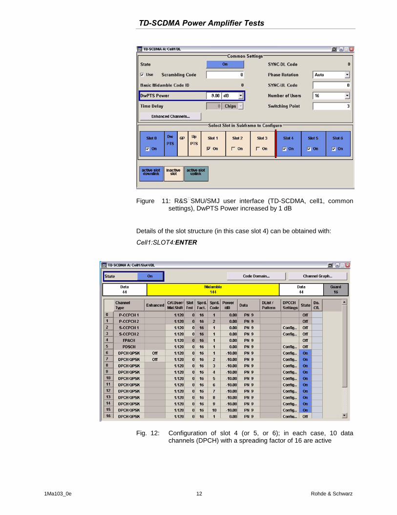
Increase the power of the DwPTS timeslot (default value -10dB) by at least 1 dB for synchronization purposes of the analyzer.
TD-SCDMA Power Amplifier Tests
1Ma103_0e 12 Rohde & Schwarz
Figure 11: R&S®SMU/SMJ user interface (TD-SCDMA, cell1, common settings), DwPTS Power increased by 1 dB
Details of the slot structure (in this case slot 4) can be obtained with:
Cell1:SLOT4:ENTER
Fig. 12: Configuration of slot 4 (or 5, or 6); in each case, 10 data channels (DPCH) with a spreading factor of 16 are active

TD-SCDMA Power Amplifier Tests
1Ma103_0e 13 Rohde & Schwarz
Single-carrier signal with 1 code channel per slot active:
MENU
BASEBAND A CONFIG:
TD-SCDMA…:STATE ON:ENTER
Reset All Cells
Predefined Settings:
Number of Dedicated Channels 3: ENTER
ACCEPT:ESC
Adjust Total Power to 0dB:Enter
Figure 13: R&S®SMU/SMJ user interface (Predefined Settings/DL) setting up 1 code channel per downlink slot (3 in total)
Adjust output power for active data channels:
Cell1:SLOT4:ENTER
Adjust the power of the active data channel from -3.01 dB to 0 dB

TD-SCDMA Power Amplifier Tests
1Ma103_0e 14 Rohde & Schwarz
Fig. 14: Configuration of slot 4 (or 5, or 6); in each case, 1 data channels (DPCH) with a spreading factor of 16 is active; power of active channel adjusted to 0 dB
Repeat power setting of active channel for slots 5 and 6.
The generator now outputs a TD-SCDMA signal for which the downlink slots 0, 4, 5 and 6 are active as well as the downlink pilot timeslot (DwPTS). 1 code channel is active per slot 4, 5 and 6 (3 in total).
The crest factor of the signal is approx. 3 dB.

TD-SCDMA Power Amplifier Tests
1Ma103_0e 15 Rohde & Schwarz
Multi-carrier signals The multi-carrier test signal required depends on the specification of the multi-carrier power amplifier. The Rohde & Schwarz generators provide the following two options:
Generation of a phase-coherent two-carrier TD-SCDMA signal (R&S®SMU with two baseband units only): If there are two baseband units in the R&S®SMU, a phase-coherent two-carrier TD-SCDMA signal can be generated with the assistance of the TD-SCDMA application firmware.
Signal generator operating sequence (8 code channels active in slot 4, 5 and 6):
MENU:
BASEBAND B CONFIG:
FREQ OFFSET: 1.6 MHz
SIGNAL ROUTING: ROUTE TO PATH A
TD-SCDMA…:STATE ON
Predefined Settings: Number of Dedicated Channels 24: ENTER
ACCEPT:ESC
TRIGGER/MARKER:TRIGGER IN/MODE:ARMED/RETRIGGER :SOURCE:INTERNAL(BASBAND A)
BASEBAND A CONFIG:
TD-SCDMA…:STATE ON:
Predefined Settings: of Dedicated Channels 24: ENTER
ACCEPT
RF/A-MOD:ON

TD-SCDMA Power Amplifier Tests
1Ma103_0e 16 Rohde & Schwarz
Generation of a phase-coherent four-carrier TD-SCDMA signal (ARB mode): TD-SCDMA multi-carrier signals (except the two-carrier signal above) require the generator's arbitrary waveform (ARB) function. The example below illustrates the generation of a four-carrier TD-SCDMA signal. Other configurations with a different number of carriers or different carrier spacings are set analogously. To keep the crest factor of the sum signal down, a code spacing that is as large as possible is selected (32) for the four TD-SCDMA carriers. This four-carrier TD-SCDMA signal (8 code channels active in slot 4, 5 and 6) is required as a test signal for the multi-carrier ACLR measurement described in Chapter 6.
Signal generator operating sequence.
MENU BASEBAND A CONFIG:TD-SCDMA…:STATE ON
: Predifined Settings: :Number of Dedicated Channels 24: ENTER :ACCEPT: ESC
:Generate Waveform File: \d(data)\tds_0
:Cell1: Scrambling Code: 32
:Generate Waveform File: \d(data)\tds_1
:Cell1: Scrambling Code: 64
:Generate Waveform File: \d(data)\tds_2
:Cell1: Scrambling Code: 96
:Generate Waveform File: \d(data)\tds_3
ESC ARB…:MULTICARRIER…:Number of Carrier: 4
:Carrier Spacing: 1.6 MHz
:Crest Factor Mode: Minimize
: Signal Period Mode: Longest File Wins
:Carrier Table: 0:State ON: File: \ tds_0
:1:State ON: File: \ tds_1
:2:State ON: File: \ tds_2
:3:State ON: File: \ tds_3
Create and Load
:ARB…:State: ON
To trigger the connected measuring instruments (spectrum analyzer or power meter), the signal generator's marker 1 output must be set to the restart signal. In this case, the restart signal provides a frame trigger signal to start the frame.
:ARB:…:Trigger/Marker…:Marker Mode: Marker 1 Restart
TD-SCDMA Power Amplifier Tests
1Ma103_0e 17 Rohde & Schwarz
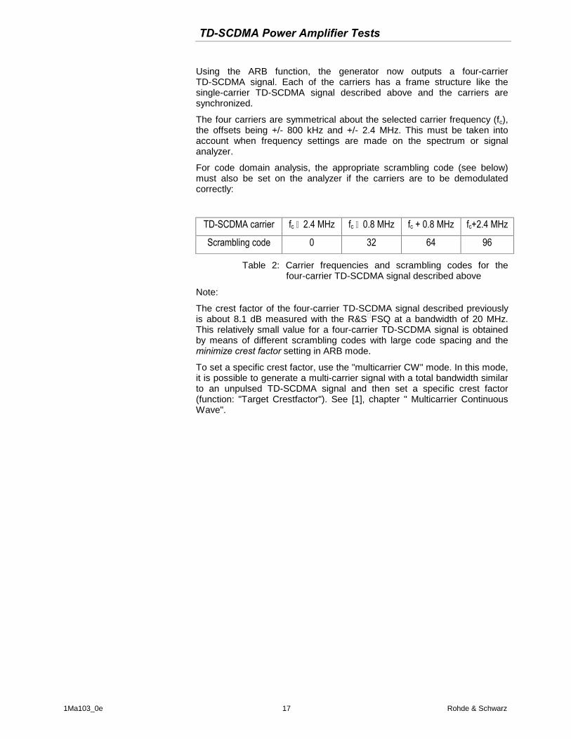
Using the ARB function, the generator now outputs a four-carrier TD-SCDMA signal. Each of the carriers has a frame structure like the single-carrier TD-SCDMA signal described above and the carriers are synchronized.
The four carriers are symmetrical about the selected carrier frequency (fc), the offsets being +/- 800 kHz and +/- 2.4 MHz. This must be taken into account when frequency settings are made on the spectrum or signal analyzer.
For code domain analysis, the appropriate scrambling code (see below) must also be set on the analyzer if the carriers are to be demodulated correctly:
TD-SCDMA carrier fc – 2.4 MHz fc – 0.8 MHz fc + 0.8 MHz fc+2.4 MHz
Scrambling code 0 32 64 96
Table 2: Carrier frequencies and scrambling codes for the four-carrier TD-SCDMA signal described above
Note:
The crest factor of the four-carrier TD-SCDMA signal described previously is about 8.1 dB measured with the R&S®FSQ at a bandwidth of 20 MHz. This relatively small value for a four-carrier TD-SCDMA signal is obtained by means of different scrambling codes with large code spacing and the minimize crest factor setting in ARB mode.
To set a specific crest factor, use the "multicarrier CW" mode. In this mode, it is possible to generate a multi-carrier signal with a total bandwidth similar to an unpulsed TD-SCDMA signal and then set a specific crest factor (function: "Target Crestfactor"). See [1], chapter " Multicarrier Continuous Wave".

TD-SCDMA Power Amplifier Tests
1Ma103_0e 18 Rohde & Schwarz
6 TD-SCDMA Transmit Measurements One of the single carrier TD-SCMDA test signals described in chapter 5 is required for the measurements below apart from multi-carrier ACLR measurements, which require the four-carrier test signal.
Power meter measurements
Output power (TS 25.142 chap. 6.2) and gain Use the 8 channel test signal described in chapter 5 for these tests.
Accurate power measurement at the amplifier output is critical. The amplifier must deliver the requested nominal power and meet the specifications, for example for ACLR, at exactly that power. Even though modern spectrum analyzers such as the R&S®FSP, R&S®FSU or R&S®FSQ have an excellent absolute-power measurement accuracy (0.3 dB), a power meter will always be the first choice for best accuracy. The R&S®NRP with the R&S®NRP-Z11 or R&S®NRP-Z21 sensor is particularly well-suited for measurements on 3GPP signals. Up to four sensors can be connected to the power meter. The R&S®NRP-Z11(-Z21) sensors have a very high dynamic range of 90 dB. Modulation-dependent errors (due to the amplitude variation of the TD-SCDMA signal) are negligible. A typical measurement uncertainty can be as low as about 0.1 dB.
Measure gain at nominal output power (nominal gain) when amplifying one or more TD-SCDMA signals. Measuring with a network analyzer which uses low-level sine signals may give misleading results. To achieve maximum accuracy use high performance directional couplers in combination with a power meter (see Fig. 6 on page 6).
Gain is calculated from the following formula:
Gain/dB =
output power level(dBm) – input power level (dBm) =
power level indication Sensor 3(dBm) – power level indication Sensor 1(dBm)
Note: This is just the basic formula. Variable coupling losses and the insertion loss of couplers also have to be taken into account.
In addition to nominal gain, gain variation within the transmit band and the out-of-band gain have to be measured too. Both can be measured with the test setup in Fig. 6.

TD-SCDMA Power Amplifier Tests
1Ma103_0e 19 Rohde & Schwarz
Input return loss/input VSWR Good input matching which means high input return loss or low VSWR is essential if the power amplifier is to have specific gain and a flat frequency response.
The magnitude of the input return loss is measured by the power meter with two sensors and a bi-directional coupler (see figure 6 on page 6, sensors 1 and 2). A bi-directional coupler with a high directivity (e.g. NARDA model 3022) in combination with R&S®NRP-Z11/Z21 power sensors ensures sufficiently low measurement uncertainties.
The input return loss is calculated from the following formula:
Input return loss (dB)=
input power level (dBm) – reflected input power level (dBm) =
power level indication Sensor 1(dBm) – power level indication Sensor 2(dBm)
Power meter setup: Time gated mode (T'Gate) is recommended due to the TDMA structure of the signal. The correct setting for measurement channel A of the R&S®NRP power meter is described below. Set channels B or C analogously.
Operating sequence for the power meter:
PRESET:PRESET: Menu:[Sensor]: :Mode: T'GATE
Start of Gate: 2.98:UNIT:[ms] : Menu
End of Gate: 4.99 [ms] : Menu
ESC:ESC:Trigger:A External :: Menu
FREQ:[A]:[50MHz]:DEL/TRIG 1: 2.12 :UNIT:[GHz]: Menu
ESC:Offset xx1dB:Global
ESC
The power meter now measures the power integrated over slots 4, 5 and 6.
1 Enter an offset xx corresponding to the coupling loss at the measurement frequency introduced by the directional coupler used (see Fig. 6).
TD-SCDMA Power Amplifier Tests
1Ma103_0e 20 Rohde & Schwarz
Measurements with spectrum analyzer/signal analyzer
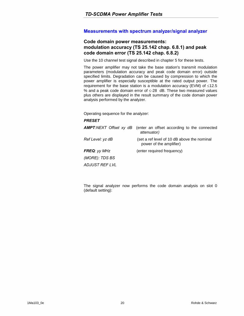
Code domain power measurements: modulation accuracy (TS 25.142 chap. 6.8.1) and peak code domain error (TS 25.142 chap. 6.8.2) Use the 10 channel test signal described in chapter 5 for these tests.
The power amplifier may not take the base station's transmit modulation parameters (modulation accuracy and peak code domain error) outside specified limits. Degradation can be caused by compression to which the power amplifier is especially susceptible at the rated output power. The requirement for the base station is a modulation accuracy (EVM) of 12.5 % and a peak code domain error of -28 dB. These two measured values plus others are displayed in the result summary of the code domain power analysis performed by the analyzer.
Operating sequence for the analyzer:
PRESET
AMPT:NEXT Offset xy dB (enter an offset according to the connected attenuator)
Ref Level: yz dB (set a ref level of 10 dB above the nominal power of the amplifier)
FREQ: yy MHz (enter required frequency)
(MORE): TDS BS
ADJUST REF LVL
The signal analyzer now performs the code domain analysis on slot 0 (default setting):

TD-SCDMA Power Amplifier Tests
1Ma103_0e 21 Rohde & Schwarz
A
TRG
B
EXT
Offset 31 dB
Ref 36.0
dBm
Ref 36.0
dBm
Ref 36.0
dBm
1 CLRWR
BS,TDS:CODE POWER
CF 2.01 GHzdB TOT
Chan 1.16
Slot 0
Start Code 1 1 Code/ Stop Code 16
LVL
Ref 36.0
dBm
Ref 36.0
dBm
Ref 36.0
dBm
1 CLRWR
RESULT SUMMARY TABLE
CF 2.01 GHzOffset 31 dB
Chan 1.16
Slot 0
LVL
Att 30 dBAtt 30 dB
DR 17.6 ksps
Att 30 dBAtt 30 dB
DR 17.6 ksps
-63
-56
-49
-42
-35
-28
-21
-14
-7
GLOBAL RESULTS FOR SET 0:
Chip Rate Error 0.01 ppm Trg to Frame -60 ns
SLOT RESULTS
P Data 23.05 dBm Carr Freq Err -929.96 mHz
P D1 23.05 dBm IQ Imbal/Offs 0.08/0.55 %
P D2 23.05 dBm RHO 1.0000
P Midamble 23.05 dBm Composite EVM 0.62 %
Active Channels 2 Pk CDE(SF 16) -55.44 dB
CHANNEL RESULTS
Channel.SF 1.16 Data Rate 17.6 kbps
ChannelPwr Rel -3.01 dB ChannelPwr Abs 20.04 dBm
Symbol EVM 0.21 %rms Symbol EVM 0.44 %Pk
Fig. 15: Default setting for the code domain analysis with the code domain power displayed at the top and the result summary at the bottom (for slot 0)
The code channels P-CCPCH1 and P-CCPCH2 are turned on; all other code channels are turned off.
Under slot results, the result summary also includes the frequency error, the composite EVM (modulation accuracy) and the peak code domain error for slot 0. The symbol EVM (RMS and Pk value) for code channel 1 is shown under channel results.

TD-SCDMA Power Amplifier Tests
1Ma103_0e 22 Rohde & Schwarz
Measurement on slot 5:
Code domain analysis can also be performed on one of the other slots by selecting its slot number.
Analyzer operating sequence (measurement on slot 5, starting from the previous setting):
SETTINGS:CAPTURE SETTINGS:SELECT SLOT: 5: ENTER
Ten data channels, each with a spreading factor of 16, are active. Compared with slot 0, the power is 7 dB higher (see the power displays for P data , P 01, P 02 and P midamble).
A
TRG
B
EXT
Offset 31 dB
Ref 36.0
dBm
Ref 36.0
dBm
Ref 36.0
dBm
1 CLRWR
BS,TDS:CODE POWER
CF 2.01 GHzdB TOT
Chan 1.16
Slot 5
Start Code 1 1 Code/ Stop Code 16
LVL
Ref 36.0
dBm
Ref 36.0
dBm
Ref 36.0
dBm
1 CLRWR
RESULT SUMMARY TABLE
CF 2.01 GHzOffset 31 dB
Chan 1.16
Slot 5
LVL
Att 30 dBAtt 30 dB
DR 17.6 ksps
Att 30 dBAtt 30 dB
DR 17.6 ksps
-63
-56
-49
-42
-35
-28
-21
-14
-7
GLOBAL RESULTS FOR SET 0:
Chip Rate Error 0.01 ppm Trg to Frame -60 ns
SLOT RESULTS
P Data 30.04 dBm Carr Freq Err 3.36 mHz
P D1 30.04 dBm IQ Imbal/Offs 0.07/0.23 %
P D2 30.04 dBm RHO 1.0000
P Midamble 30.04 dBm Composite EVM 0.31 %
Active Channels 10 Pk CDE(SF 16) -60.97 dB
CHANNEL RESULTS
Channel.SF 1.16 Data Rate 17.6 kbps
ChannelPwr Rel -10.00 dB ChannelPwr Abs 20.04 dBm
Symbol EVM 0.23 %rms Symbol EVM 0.52 %Pk
Fig. 16: Default setting for the code domain analysis with the code domain power displayed at the top and the result summary at the bottom (for slot 5)

TD-SCDMA Power Amplifier Tests
1Ma103_0e 23 Rohde & Schwarz
Gating of analyzer for spectrum measurements: TD-SCDMA signals are burst signals. To obtain stable results when spectrum measurements are made on burst signals, acquisition of measurement data can only be acquired when the slots are active. This is achieved by gating the analyzer. The analyzer sweeps or measures only when the slots are active.
Within the TD-SCDMA application firmware, the trigger/gate settings are set by default to measure slots 4 to 6 for all spectrum measurements such as power, ACLR, multi-carrier ACLR, spectrum emission mask, occupied bandwidth, power vs time and signal statistics. The default settings are as follows:
Trigger:Gate Settings
Trigger External:Polarity POS
Gate Delay: 2.975 ms
Gate Length: 2.015 ms
Ref 28 dBm Att 45 dB
*
Offset 21 dB
BS,TDS:ADJ CHANNEL
1 RMAVG
A
TRGLVL
PA
RBW 30 kHz
VBW 300 kHz
*
Center 2.01 GHz 600 µs/
SWT 6 ms
-120
-100
-80
-60
-40
-20
0
20
GDGL
Fig. 17: Gate settings for TD-SCDMA (default setting)
To change to another slot adjust START SLOT and STOP SLOT within the ADAPT TO SIGNAL menu. All spectrum measurements as stated above are then carried out for that slot (or slots).

TD-SCDMA Power Amplifier Tests
1Ma103_0e 24 Rohde & Schwarz
Output power (TS 25.142 chap. 6.2): Use the 8 channel test signal described in chapter 5 for this test.
If no power meter is available, the measurement can be performed with the analyzer instead of the power meter. The power measurement provided by the TD-SCDMA application firmware performs a gated channel-power measurement by means of integrating the power in the frequency domain.
Operating sequence for the analyzer:
PRESET
AMPT:NEXT Offset xy dB (enter an offset according to the connected attenuator)
Ref Level: yz dB (set a ref level of 10 dB above the nominal power of the amplifier)
FREQ: yy MHz (enter required frequency)
MORE:MORE TDS BS
MEAS: POWER
ADAPT TO SIGNAL: AUTO LEVEL & TIME
Ref 37 dBm Att 55 dB
**
Offset 20 dB
BS,TDS:CHAN POWER
1 RMAVG
* A SGLGATTRGLVL
PA
RBW 30 kHz
VBW 300 kHz
SWT 1.05 s*
Center 2.01 GHz Span 3 MHz300 kHz/
-100
-80
-60
-40
-20
0
20
Tx Channel TD-SCDMA Bandwidth 1.6 MHz Power 30.01 dBm
Fig. 18: Power measurement provided by the TD-SCDMA application software (integration in the frequency domain) at a spreading factor of 16 in slots 4, 5 and 6
Note: The ripple in the spectrum is due to the constant midamble with a test signal required by TS25.142 e.g. Table 6.1A in chap. 6.2.4.1.2. With a spreading factor of 16 it has a length of 144 bits and is relatively long in comparison with the pseudo-random data bits (2 x 44 bits). By comparison, for spreading factor 1, the length of the data bits is 2 x 704 bits and the resulting spectrum has nearly no ripple.

TD-SCDMA Power Amplifier Tests
1Ma103_0e 25 Rohde & Schwarz
Offset 30 dB
BS,TDS:CHAN POWER
A
LVL
Ref 36 dBm Att 15 dB
RBW 30 kHz
VBW 300 kHz
**
Center 2.01 GHz Span 3 MHz300 kHz/
1 RMCLRWR
GATTRG
EXT
SWT 1.3 s*
*
-60
-50
-40
-30
-20
-10
0
10
20
30
Tx Channel TD-SCDMA Bandwidth 1.6 MHz Power 29.18 dBm
Fig. 19: Flat and symmetrical spectrum for a spreading factor of 1 in slots 4, 5 and 6
Quick power measurement in spectrum analysis mode using the time domain power function
As a further alternative, the power in slots of interest can also be determined in spectrum analysis mode with a zero span measurement (time domain power measurement). The measurement times are significantly reduced compared with measurements based on integration in the frequency domain.
Operating sequence for the analyzer:
PRESET
AMPT:NEXT Offset xy dB (enter an offset according to the connected attenuator)
Ref Level: yz dB (set a ref level of 10 dB above the nominal power of the amplifier)
FREQ: yy MHz (enter the required frequency)
SPAN: ZERO SPAN
TRIGGER: EXTERN:POS
SWEEP: SWEEPTIME MANUAL 6 ms
BW: RES BW MANUAL 10 MHz
MEAS: TIME DOMAIN POWER
START LIMIT 2.98 ms
STOP LIMIT 4.99 ms
TRACE: DETECTOR: RMS

TD-SCDMA Power Amplifier Tests
1Ma103_0e 26 Rohde & Schwarz
Ref 40 dBm
Offset 30 dB
CLRWR
A
LVL
Att 35 dB
TRG
RBW 10 MHz
SWT 6 ms
VBW 10 MHz
*1 RM
Center 2.01 GHz 600 µs/
EXT
-60
-50
-40
-30
-20
-10
0
10
20
30
40
1
Marker 1 [T1 ]
30.16 dBm
2.980769 ms
POWER [T1]
RMS 29.92 dBm
T2T1
Fig. 20: Power measurement using the time domain power function in the spectrum analyzer mode
Crest factor measurement Crest factor measurement is not stipulated in TS 25.142. Its main purpose is to check the test signal or the amplifier output signal. A change (reduction) in the crest factor of the amplifier output signal relative to the signal at the amplifier input indicates amplifier compression.
Rohde & Schwarz analyzers provide crest factor measurement as part of the Complementary Cumulative Distribution Function (CCDF) measurement. The CCDF curve is a plot of relative power versus probability. In the TD-SCDMA application firmware, the CCDF measurement is gated and only performed on selected slots. In the default state, these are slots 4, 5 and 6.

TD-SCDMA Power Amplifier Tests
1Ma103_0e 27 Rohde & Schwarz
Operating sequence for the analyzer:
PRESET
AMPT:NEXT Offset xy dB (enter an offset according to the connected attenuator)
Ref Level: yz dB (set a ref level of 10 dB above the nominal power of the amplifier)
FREQ: yy MHz (enter required frequency)
MORE:MORE TDS BS
MEAS: SIGNAL STATISTICS : CCDF
ADAPT TO SIGNAL: AUTO LEVEL & TIME
Offset 30.8 dB
BS,TDS:SIGNAL STAT
A
LVL
Ref 40 dBm Att 35 dB
RBW 10 MHz
AQT 6.25 ms
Center 2.12 GHz 2 dB/ Mean Pwr + 20 dB
1 SACLRWR
GATTRG
1E-5
1E-4
1E-3
0.01
0.1
Complementary Cumulative Distribution Function NOF samples: 100000, Usable BW: 11.2MHz
Trace 1 Mean 30.00 dBm Peak 36.57 dBm Crest 6.57 dB
10 % 3.46 dB 1 % 6.38 dB .1 % 6.51 dB .01 % 6.57 dB
Fig. 21: Crest factor display as part of the CCDF measurement of the TD-SCDMA application firmware (8 channel test signal)

TD-SCDMA Power Amplifier Tests
1Ma103_0e 28 Rohde & Schwarz
Adjacent channel leakage power ACLR (TS 25.142 chap. 6.6.2.2) For base stations, TS25.142 specifies an ACLR of >40 dB in the adjacent channel and an ACLR of >45 dB in the alternate channel. The ACLR of the base station power amplifier must be higher.
Use the 8 channel test signal described in chapter 5 for this test.
Performance of the R&S®SMU with R&S®FSU/FSQ
Using the analyzers noise correction function R&S®SMU with R&S®FSU/FSQ, ACLR values of typ. -66 dB in the adjacent channel, and -80 dB in the alternate channel are obtained, providing a more than sufficiently large margin for the values to be tested.
Operating sequence for the analyzer:
PRESET
AMPT:NEXT Offset xy dB (enter an offset according to the connected attenuator)
Ref Level: yz dB (set a ref level of 10 dB above the nominal power of the amplifier)
FREQ: yy MHz (enter required frequency)
MORE:MORE TDS BS
MEAS: ACLR
ADAPT TO SIGNAL: AUTO LEVEL & TIME
Ref 29 dBm
**
Offset 31 dB
BS,TDS:ADJ CHANNEL
CLRWR
A
GATTRGLVL
RBW 30 kHz
VBW 300 kHz
SWT 1.3 sAtt 10 dB
1 RM
*
NOR
*
Center 2.12 GHz Span 11.6 MHz1.16 MHz/
-70-60
-50
-40
-30
-20
-10
0
10
20
Tx Channel TD-SCDMA Bandwidth 1.28 MHz Power 30.12 dBm
Adjacent Channel Bandwidth 1.28 MHz Lower -66.10 dB Spacing 1.6 MHz Upper -67.21 dB
Alternate Channel Bandwidth 1.28 MHz Lower -80.86 dB Spacing 3.2 MHz Upper -80.76 dB
Fig. 22: Typical ACLR performance of the R&S®SMU with R&S®FSU/FSQ

TD-SCDMA Power Amplifier Tests
1Ma103_0e 29 Rohde & Schwarz
Performance of the R&S®SMU with R&S®FSP
An adequate margin for the power amplifier's ACLR values can also be achieved with the R&S®SMU with R&S®FSP, typical values being -63 dB in the adjacent channel and -74 dB in the alternate channel.
Ref 28 dBm
**
Offset 31 dB
BS,TDS:ADJ CHANNEL
CLRWR
A
GATTRGLVL
RBW 30 kHz
VBW 300 kHz
SWT 1.05 sAtt 20 dB
1 RM
*
NOR
*
Center 2.12 GHz Span 11.6 MHz1.16 MHz/
-70
-60
-50
-40
-30
-20
-10
0
10
20
Tx Channel TD-SCDMA Bandwidth 1.28 MHz Power 30.24 dBm
Adjacent Channel Bandwidth 1.28 MHz Lower -63.39 dB Spacing 1.6 MHz Upper -63.42 dB
Alternate Channel Bandwidth 1.28 MHz Lower -74.50 dB Spacing 3.2 MHz Upper -74.03 dB
Fig. 23: R&S®SMU and R&S®FSP ACLR performance
Multi-carrier ACLR (TS 25.142 chap. 6.6.2.2) Power amplifiers for multi-carrier base stations have e to meet particularly stringent requirements. According to TS 25.142, the ACLR limits of 40 dB (in the adjacent channel) and 45 dB (in the alternate channel) must be met by the carriers above and below the carriers in use.
To set up a suitable test signal (four-carrier signal) on the R&S®SMU or R&S®SMJ see chapter 5, page 16.
Operating sequence for the analyzer:
PRESET
AMPT:NEXT Offset xy dB (enter an offset according to the connected attenuator)
Ref Level: yz dB (set a ref level of 10 dB above the nominal power of the amplifier)
FREQ: yy MHz (enter required frequency)
MORE:MORE TDS BS
MEAS: ACLR
ADAPT TO SIGNAL: AUTO LEVEL & TIME

TD-SCDMA Power Amplifier Tests
1Ma103_0e 30 Rohde & Schwarz
Additional setting on the R&S®SMU for optimal ACLR with multi-carrier signals:
MENU:IQ-Mod:IQ-Settings:Internal Baseband:Baseband Gain: -3 dB.
As a consequence, an R&S®SMU with R&S®FSU/FSQ achieves a typical ACLR performance of approximately 67 dB in the adjacent channel and 68 dB in the alternate channel.
Ref 30 dBm
**
Offset 31 dB
BS,TDS:MC ACLR
CLRWR
A
GATTRGLVL
RBW 30 kHz
VBW 300 kHz
SWT 1.3 sAtt 20 dB*
1 RM
NOR
*
Center 2.12 GHz Span 12.9 MHz1.29 MHz/
-60
-50
-40
-30
-20
-10
0
10
20
Standard: TD-SCDMA
Tx Channels
Ch1 24.67 dBm(Ref)
Ch2 24.76 dBm
Ch3 24.68 dBm
Ch4 24.93 dBm
Total 30.78 dBm
Adjacent Channel
Lower -67.40 dB
Upper -68.42 dB
Alternate Channel
Lower -67.99 dB
Upper -68.71 dB
Fig. 24: Typical performance of an R&S®SMU with R&S®FSU/FSQ for adjacent channel measurements on a four-carrier TD-SCDMA signal

TD-SCDMA Power Amplifier Tests
1Ma103_0e 31 Rohde & Schwarz
Spectrum emission mask (TS 25.142 chap. 6.6.2.1) Use the 8 channel test signal described in chapter 5 for this test.
For some regions, TS25.142, chap. 6.6.2.1 stipulates a spectrum emission mask for single-carrier transmitters. This mask is illustrated schematically below. The limit lines depend on the maximum output power of the base station. There must be sufficient margin between the base station power-amplifier's spectrum emission curve and the limit lines.
Fig. 25: Diagram showing the spectrum emission mask for TD-SCDMA base stations
To assess power emissions, the analyzer measures the signal power up to 2.3 MHz with a 30 kHz filter and from 2.3 MHz to 4 MHz with a 1 MHz filter. The curve obtained is compared with the limit line specified in TS 25.142 chap. 6.6.2.21 which depends on the base station's power (in this test setup the power amplifier's specified power).
Operating sequence for the analyzer:
PRESET
AMPT:NEXT Offset xy dB (enter an offset according to the connected attenuator)
Ref Level: yz dB (set a ref level of 10 dB above the nominal power of the amplifier)
FREQ: yy MHz (enter required frequency)
MORE:MORE TDS BS
MEAS: SPECTRUM EM MASK
ADAPT TO SIGNAL: AUTO LEVEL & TIME

TD-SCDMA Power Amplifier Tests
1Ma103_0e 32 Rohde & Schwarz
The typical performance of the spectrum emission mask measurement for the R&S®SMU with R&S®FSU/FSQ or R&S®FSP at an amplifier output power of 30 dBm is shown in the two measurement diagrams below, including:
The spectrum of the TD-SCDMA signal over slots 4 to 6
The limit line complies with TS25.142 chap. 6.6.2.1.2 (table 6.4 A, output power: 26 dBm to 34 dBm)
Information about limit-line violations (Pass/Fail information; in this case: Pass)
Ref 38 dBm Att 15 dB *
Offset 30 dB
BS,TDS:SP EM MASK
1 RMCLRWR
A
GATTRGLVL
SWT 1.3 s*
Center 2.12 GHz Span 8 MHz800 kHz/
-60
-50
-40
-30
-20
-10
0
10
20
30
1
Marker 1 [T1 ]
-40.97 dBm
2.116000000 GHz
CH PWR 30.06 dBm
LIMIT CHECK PASS
26 <= P <34
Fig. 26: Demonstration of the dynamic range for the spectrum emission mask measurement at 30 dBm using the R&S®SMU with R&S®FSU/R&S®FSQ

TD-SCDMA Power Amplifier Tests
1Ma103_0e 33 Rohde & Schwarz
Ref 30 dBm Att 15 dB *
Offset 30 dB
BS,TDS:SP EM MASK
1 RMCLRWR
A
GATTRGLVL
SWT 1.05 s*
Center 2.12 GHz Span 8 MHz800 kHz/
-70
-60
-50
-40
-30
-20
-10
0
10
20
30 CH PWR 29.94 dBmLIMIT CHECK PASS
26 <= P <34
Fig. 27: Demonstration of the dynamic range for the spectrum emission mask measurement at 30 dBm using the R&S®SMU with R&S®FSP
Power versus Time (Transmit ON/OFF power TS 25.142 chap. 6.5)
Use the 8 channel test signal described in chapter 5 for this test.
TS 25.142 chapter 6.5 stipulates an extreme dynamic range for this test. During the transmit OFF period, an absolute level of -82 dBm (measured with the 1.28 MHz bandwidth) must not be exceeded.
Fig. 28: Transmit On/Off template in line with TS25.142 chap. 6.5.2
For an output power of +30 dBm, for example, this means a dynamic range of 112 dB at a measurement bandwidth of 1.28 MHz.

TD-SCDMA Power Amplifier Tests
1Ma103_0e 34 Rohde & Schwarz
To achieve this, base station power amplifiers must have special design features, for example to turn off the amplifier's output signal. Measures must be taken to prevent the amplifier's input noise being amplified and fed to the output during the OFF period. (The noise from the signal generator used as the drive source is also suppressed in the OFF period as it would otherwise have a negative effect on the dynamic range that could be obtained.)
Rohde & Schwarz signal analyzers provide a high dynamic measurement mode2 for the power versus time measurement. A preliminary measurement is used to determine the reference level of the selected ON timeslot (in the default state, slots 4, 5, 6). Using the reference level determined with Auto Level&Time, the power during the OFF time is measured keeping the attenuation as low as possible and with the preamplifier turned on. Each measurement is averaged over 100 subframes (default setting of the high dynamic measurement mode).
2 The option R&S®FS-K25 "Electronic Attenuator and 20 dB Preamplifier" is required to obtain the maximum dynamic range in this case

TD-SCDMA Power Amplifier Tests
1Ma103_0e 35 Rohde & Schwarz
Operating sequence for the analyzer:
PRESET
AMPT:NEXT Offset xy dB (enter an offset according to the connected attenuator)
Ref Level: yz dB (set a ref level of 10 dB above the nominal power of the amplifier)
FREQ: yy MHz (enter required frequency)
MORE:MORE TDS BS
MEAS: POWER VS TIME:HIGH DYNAMIC
ADAPT TO SIGNAL: AUTO LEVEL & TIME
START MEAS
*
Offset 6 dB
BS,TDS:POWER VS TIME
1 RMAVG
A SGL
TRGLVL
RBW 1.28 MHz
VBW 10 MHz
SWT 2.4 ms
eAtt 5 dB*
Ref 30 dBm Att 25 dB
Center 2.12 GHz 240 µs/
-120
-100
-80
-60
-40
-20
0
20
SWP 100 of 100
LIMIT CHECK PASS
BPTF3
Fig. 29: Power vs time measurement with the R&S®FSU/Q; dynamic range at 25 dBm on the amplifier output

TD-SCDMA Power Amplifier Tests
1Ma103_0e 36 Rohde & Schwarz
7 Glossary ARB Arbitrary
ACLR Adjacent channel leakage power ratio
BS Base station
CCDF Complementary distributive distribution function
CWTS China Wireless Telecommunication Standard group (http://www.cwts.org)
DL Downlink
DwPTS Downlink pilot timeslot
GP Guard period
Mcps Mega chips/s
PA Power amplifier
TS1,TS2 Timeslot 1, 2
TDD Time division duplexing
TD-SCDMA Time division synchronous code division multiple access
UpPTS Uplink pilot timeslot
UMTS Universal mobile telecommunications system
UTRA UMTS Terrestrial radio access
8 References [1] Operating Manual R&S®SMU Vector Signal Generator 1007.9845.32-09-I [2] Operating Manual R&S®SMJ Vector Signal Generator 1403.7458.32-04-IN [3] Software Manual R&S®FS–K76 TD–SCDMA Base Station Test Application
Firmware 1300.7304.44-03 [4] Operating Manual R&S®NRP Power Meter 1144.1400.12-04- [5] Data Sheet R&S®SMJ100A Vector Signal Generator PD 5213.5074.22 [6] Data Sheet R&S®SMATE Vector Signal Generator PD0758.1893.22 [7] Data Sheet R&S®SMU200A Vector Signal Generator PD 0758.0197.22 [8] Application Firmware R&S®FS–K76 1300.7304.44-03 [9] ETSI TS 125 105 V7.1.0 (2005-12) [10] ETSI TS 125 142 V7.1.0 (2005-12)
9 Additional Information Please send any comments or suggestions about this Application Note to [email protected].

TD-SCDMA Power Amplifier Tests
1Ma103_0e 37 Rohde & Schwarz
10 Ordering information Power meter and options R&S® NRP Power Meter 1138.3004.02 R&S® NRP-Z11 Diode Power Sensor
200 pW to 200 mW 10 MHz to 8 GHz
1138.3004.02
R&S® NRP-Z21 Diode Power Sensor
200 pW to 200 mW 100 MHz to 18 GHz
1137.6000.02
R&S® NRP-Z3 USB Adapter (active) with trigger port
1146.7005.02
Signal analyzer, spectrum analyzer and options R&S® FSP3 9 kHz to 3 GHz 1093.4495.03 R&S® FSP7 9 kHz to 7 GHz 1093.4495.07 R&S® FSP13 9 kHz to 13 GHz 1093.4495.13 R&S® FSP-B25
Electronic Attenuator, 0 dB to 30 dB, 5 dB steps, integrated preamplifier for FSP3 and FSP7
1129.7746.02
R&S® FSU3 20 Hz to 3.6 GHz 1129.9003.03 R&S® FSU8 20 Hz to 8 GHz 1129.9003.08 R&S® FSU26 20 Hz to 26.5 GHz 1129.9003.26 R&S® FSQ3 20 Hz to 3.6 GHz 1155.5001.03 R&S® FSQ8 20 Hz to 8 GHz 1155.5001.08 R&S® FSQ26 20 Hz to 26.5 GHz 1155.5001.26 R&S® FSU-B25
Electronic Attenuator and 20 dB Preamplifier (3.6 GHz)
1044.9298.02
R&S® FS-K76 3GPP TD-SCDMA BTS Application Firmware
1300.7291.02
Vector signal generator and otions R&S
® SMU200A Vector Signal Generator 1141.2005.02
R&S®
SMU-B102 RF Path A: 100 kHz to 2.2 GHz 1141.8503.02
R&S®
SMU-B103 RF Path A: 100 kHz to 3 GHz 1141.8603.02
R&S®
SMU-B104 RF Path A: 100 kHz to 4 GHz 1141.8703.02
R&S®
SMU-B106 RF Path A: 100 kHz to 6 GHz 1141.8803.02
R&S®
SMU-B9 Baseband with ARB (128 Msample) 1404.1501.02
R&S®
SMU-B10 Baseband with ARB (64 Msample) 1141.7007.02
R&S®
SMU-B11 Baseband with ARB (16 Msample) 1159.8411.02
R&S®
SMU-B13 Baseband Main Module 1141.8003.02
R&S®
SMU-K50 Digital Standard TD-SCDMA 1161.0966.02
R&S®
SMU-B31 High-Power Output 1159.8011.02
R&S®
SMU-K250 Digital Standard TD-SCDMA (with WINIQSIM2™)
1408.6314.02
R&S
® SMJ100A Vector Signal Generator 1404.4507.02
R&S®
SMJ-B103 RF Path B: 100 kHz to 3 GHz 1403.8502.02
R&S®
SMJ-B9 Baseband with ARB (128 Msample) 1404.1501.02
R&S®
SMJ-B10 Baseband with ARB (64 Msample) 1403.8902.02
R&S®
SMJ-B11 Baseband with ARB (16 Msample) 1403.9009.02
R&S®
SMJ-B13 Baseband Main Module 1403.9109.02
R&S®
SMJ-K50 Digital Standard TD-SCDMA 1404.1660.02
R&S®
SMJ-K250 Digital Standard TD-SCDMA (with WINIQSIM2™)
1404.1316.02
For additional information about power meters, signal generators, spectrum analyzers and signal analyzers, visit the Rohde & Schwarz website www.rohde-schwarz.com.

TD-SCDMA Power Amplifier Tests
1Ma103_0e 38 Rohde & Schwarz
ROHDE & SCHWARZ GmbH & Co. KG . Mühldorfstraße 15 . D-81671 München . Postfach 80 14 69 . D-81614 München .
Tel (089) 4129 -0 . Fax (089) 4129 - 13777 . Internet: http://www.rohde-schwarz.com
This application note and the supplied programs may only be used subject to the conditions of use set out in the download area of the Rohde & Schwarz website.