Testing Telecom Packet Clocks
42
1 Testing Telecom Packet Clocks Kishan Shenoi, Chip Webb, Jason Nutt, Jarek Zdziech Ixia
Transcript of Testing Telecom Packet Clocks

This material is for informational purposes only and subject to change without notice. It describes Ixia’s present plans to develop and make
available to its customers certain products, features and functionality. Ixia is only obligated to provide those deliverables specifically included in a
written agreement between Ixia and the customer. ©2012 Ixia. All rights reserved.
1
Testing Telecom Packet Clocks
Kishan Shenoi, Chip Webb, Jason Nutt, Jarek Zdziech
Ixia

Prelude
2
Testing Telecom Packet Clocks
• Protocol (addressed in back-up)
• Performance : Quantifying time error
Test Principles (G.8273 Annex A)
Testing Configurations (G.8273 Annex B)
Concluding Remarks
(Back-up slides for information)

Testing PTP (Packet) Clocks
Types of Clocks
• Grandmaster Clocks (T-GM)
Could be integrated with a PRTC
• Boundary Clocks (T-BC)
• Transparent Clocks (T-TC)
• Slave Clocks (T-TSC)
• Variations based on whether for full-timing-support case or not
Types of Ports
• Master ports (T-GM, T-BC)
• Slave ports (T-BC, T-TSC)
• I/O ports (T-TC)
Considerations synchronization may be different for time/frequency

Testing Master Ports
4
Boundary clock: local time-clock developed
using a slave clock synchronized to an
upstream grandmaster clock
Grandmaster clock: local time-clock
developed using a PRTC reference
(external or integrated)
G.8273 Annex A
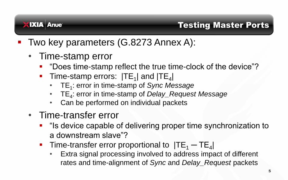
Testing Master Ports
Two key parameters (G.8273 Annex A):
• Time-stamp error “Does time-stamp reflect the true time-clock of the device”?
Time-stamp errors: |TE1| and |TE4| • TE1: error in time-stamp of Sync Message
• TE4: error in time-stamp of Delay_Request Message
• Can be performed on individual packets
• Time-transfer error “Is device capable of delivering proper time synchronization to
a downstream slave”?
Time-transfer error proportional to |TE1 ─ TE4| • Extra signal processing involved to address impact of different
rates and time-alignment of Sync and Delay_Request packets
5

Testing Master Ports
Example Test Configurations (G.8273 Annex B)
• T-GM could have external PRTC or integrated PRTC
• The cable length between the T-GM and the monitoring tap
must be calibrated

Testing Master Ports
Example Test Configurations (G.8273 Annex B)
• The cable length between the T-BC and the monitoring tap must be
calibrated
• Measuring TE1 and TE4 using 1pps identifies noise introduced by
the master side of the T-BC
Note: similar configuration
applies for T-TC testing

Testing Transparent Clocks
Effective residence time = zero (nominally) after correction
Time at reference point U and at reference point D should be
equal
G.8273 Annex A
(ns) )()( TCDU XtTtT

Testing Transparent Clocks
Test Configuration example (G.8273 Annex B)

Testing Slave Ports
Principal performance parameters (G.8273 Annex A)
Time-stamp errors TE2 and TE3 not generally visible externally
• For network limit
examine |TOUT |
• For generation
examine |TOUT – TSLV|
• Slave time-clock via
1PPS(+TOD) for T-BC
and T-TSC
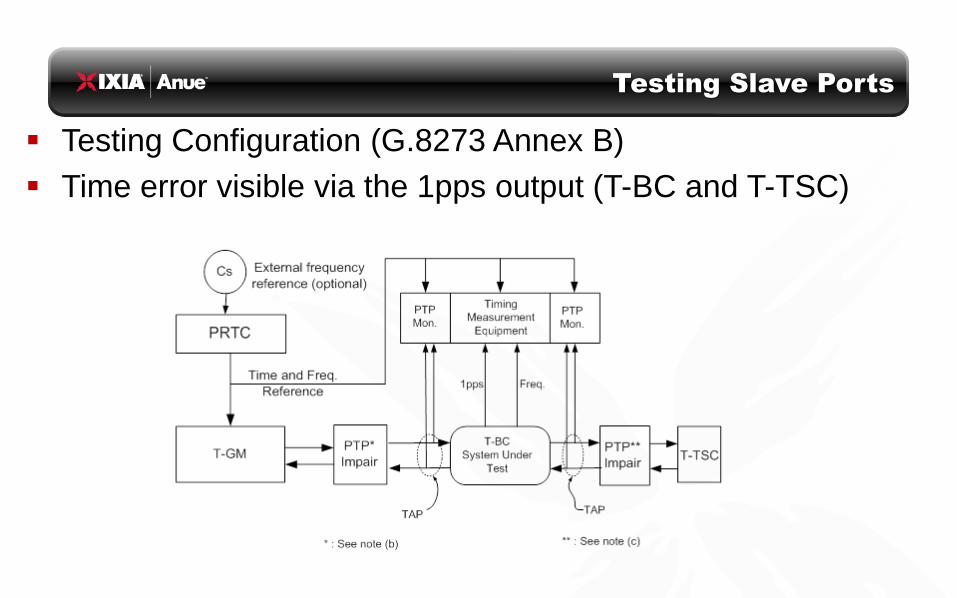
Testing Slave Ports
Testing Configuration (G.8273 Annex B)
Time error visible via the 1pps output (T-BC and T-TSC)

Testing Slave Ports
Testing Configuration (G.8273 Annex B)
Slave clock time error visible if precise value of T3 provided in
delay_request message or subsequent (not-standardized)
follow-up message

Computing Metrics
For a measured time error sequence {x(n)} or filtered time error
sequence {y(n)} (commonly proposed filter: 0.1Hz):
• Max (absolute) time error : |x(n)|max
• Max (absolute) filtered time error : |y(n)|max
• MTIE… maximum (absolute) time interval error (stability metric)
• TDEV… stability metric that describes power (and type) of noise
• MATIE… maximum (absolute) averaged time interval error
MAFE… related to MATIE
• TEDEV… standard deviation of averaged time interval error
• cTE… estimate of constant time error: average of N samples
• Other (TBD)

Special Considerations
Measuring time error (static and dynamic) increasing in importance
• “Frequency” metrics (PDV) necessary but not sufficient
Boundary clocks (and transparent clocks) are not perfect
• Effectively introduce static as well as PDV-like (dynamic) timing impairments
(time error)
Reason for impairments may be implementation dependent
• Behavior affected by sync rates and traffic loads
Testing during equipment development phase is very helpful
Test Equipment measurement granularity must be substantively better
than expected clock behavior
For measuring transit delay the time-stampers (test equipment) at “U”
and “D” must be synchronized to each other
14

15
Thank You!
Questions?

Back-up Slides
16

Metrics Mathematics
Metrics establish “strength” of time error. Different metrics focus on different
aspects of this “strength”.
Maximum absolute time error : |x(n 0)|max is the overarching time error metric
(maximum over all time)
First difference eliminates a0 : strength of {x(n+k) – x(n)} quantifies stability of
the time error
• Variations include MTIE, MATIE, TEDEV
Second difference eliminates and a0 : strength of {x(n+2k)–2x(n+k)+x(n)}
quantifies stability of the frequency (e.g. TDEV, ADEV, MDEV)
17
Clock
under
test
(CUT)
+ Reference
Clock
Time error {x(n 0)}
Clock
Error
model 0000 nnanx
a0 : constant time error
: frequency offset
Noise terms (“random”)

Metrics Mathematics
Possible to separate “high-band” and “low-band”
time error by filtering {x(n)} to get {y(n)}
• Identifies the component that could be in the
pass-band of the down-stream clock
Some metrics include an average over one
observation interval (k samples) that is
incorporated into the formula
• MATIE, TEDEV, TDEV, MDEV
18
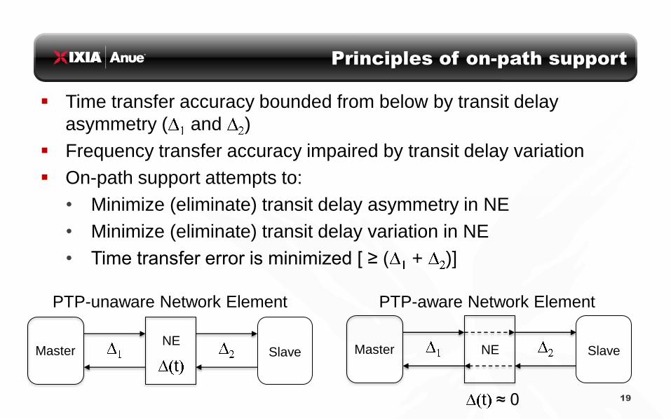
Principles of on-path support
Time transfer accuracy bounded from below by transit delay
asymmetry ( and )
Frequency transfer accuracy impaired by transit delay variation
On-path support attempts to:
• Minimize (eliminate) transit delay asymmetry in NE
• Minimize (eliminate) transit delay variation in NE
• Time transfer error is minimized [ ≥ ( + )]
19
Master Slave NE
t
PTP-unaware Network Element
Master Slave NE
t ≈ 0
PTP-aware Network Element

Principles of on-path support
Consider (hypothetical) slave deployed just before or just after NE
• Without on-path support the slave at B has different time/wander behavior
compared to the slave at A; performance is load dependent
• With on-path support the slave at B has (ideally) the same time/wander
behavior compared to the slave at A; performance should be load independent
Two forms of on-path support:
• Boundary clock ─ “regenerates” master
• Transparent clock ─ acts “invisible” (by providing correction)
20
Master
PTP
unaware
NE
A B
Slave at A ≠ Slave at B
Master
PTP
aware
NE
A B
Slave at A ≈ Slave at B

Testing distribution of timing on IP/Ethernet
Networks
21
Solutions 1588v2 – PTP (Frequency, Phase & ToD)
• Grand Master
• Boundary Clocks
• Slave Clocks
• Transparent Clock
ESMC – Sync-E (Frequency)
• Physical Layer
• 1PP implementation
• Telecom Profile G.8265.1 for frequency
• measure min/max/ave offset, path delay, all message
counters and rates
• Slave scalability – need to be able to capacity plan
• Best Master Clock Algorithm
Hybrid Mode
Options: • IPv4 / IPv6
• Multicast / Unicast
• One step / Two step
• Delay-Request/Response, Peer Delay or One-way
• Priority: 802.3P, IP ToS or DiffServ
• Clock parameters
• Configurable message rates
Time:
Protocol:
Real W
orld
Testin
g
1588v2 Protocol Testing – Master / Slave
22
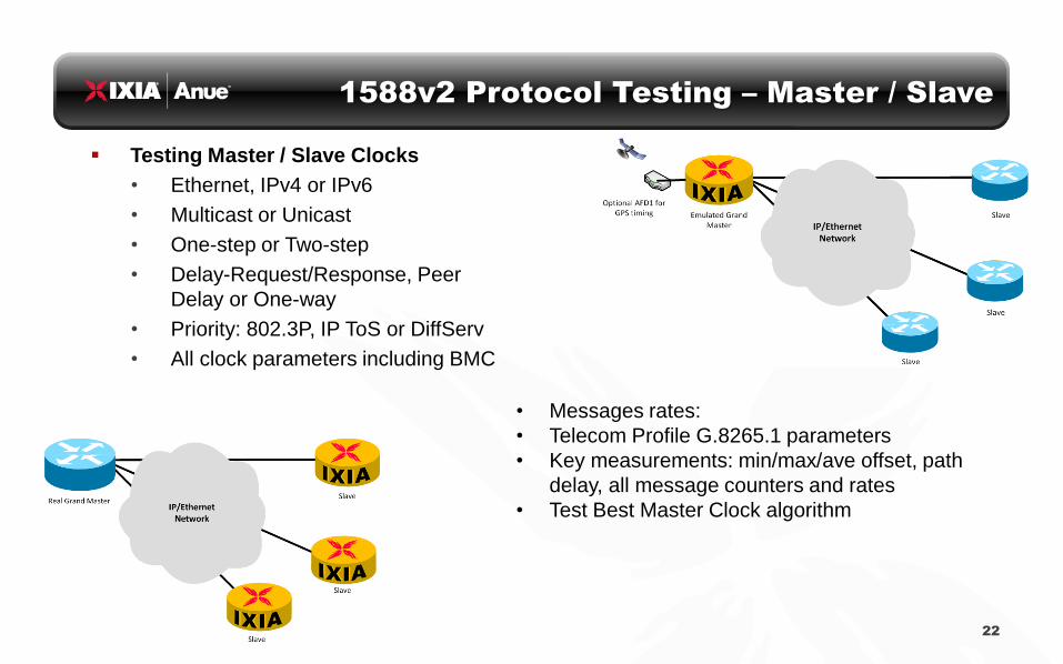
Testing Master / Slave Clocks
• Ethernet, IPv4 or IPv6
• Multicast or Unicast
• One-step or Two-step
• Delay-Request/Response, Peer
Delay or One-way
• Priority: 802.3P, IP ToS or DiffServ
• All clock parameters including BMC
• Messages rates:
• Telecom Profile G.8265.1 parameters
• Key measurements: min/max/ave offset, path
delay, all message counters and rates
• Test Best Master Clock algorithm

1588v2 Protocol Testing – Boundary / Transparent
23
Test boundary clock ability to be slave to the master and master to connected slaves Test transparent clock
ability to accurately modify the correction field (CF) of each PTP packet

What To Test for PTP Equipment
G.8261 Test Cases
• PDV of network emulated using precise profiles
with Anue 3500
• Wander on the recovered clock of slave is
evaluated according to the ITU-T standards
(MTIE & TDEV)
Time Error & Phase
• Compare 1PPS of master with slave LTE requirement: <1.5us
• Measure PTP packet time error Boundary Clock timestamp accuracy (time error)
Grandmaster Clock timestamp accuracy (time error)
• Transparent Clock correction field accuracy
MTIE Plot example
• Top line is mask
• Bottom line is measured TIE
• Staying below the mask
indicates a “pass”`
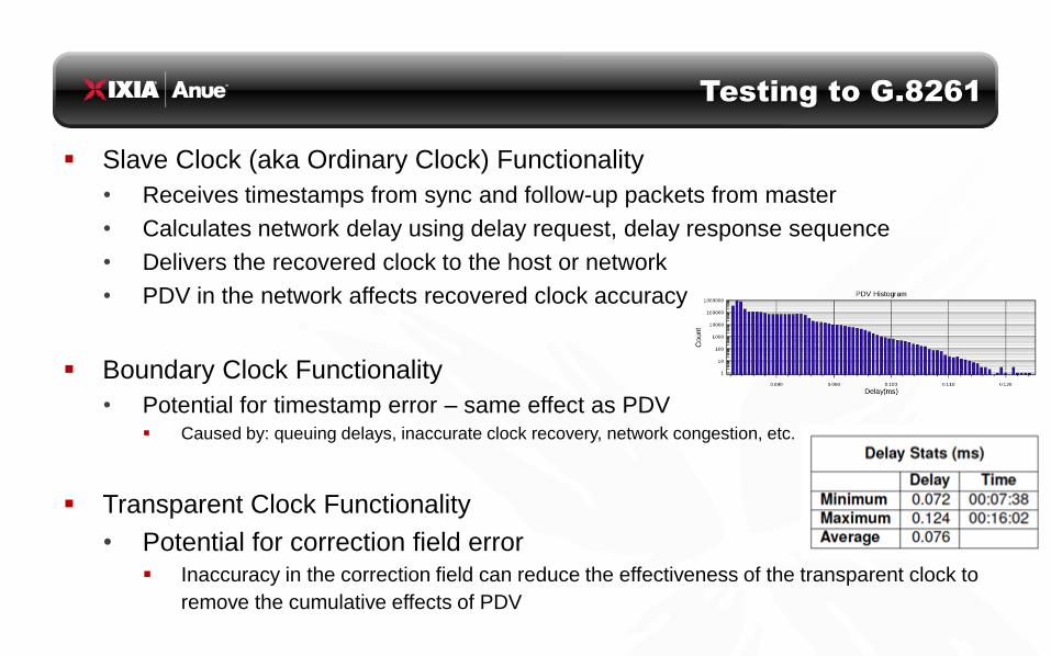
Testing to G.8261
Slave Clock (aka Ordinary Clock) Functionality
• Receives timestamps from sync and follow-up packets from master
• Calculates network delay using delay request, delay response sequence
• Delivers the recovered clock to the host or network
• PDV in the network affects recovered clock accuracy
Boundary Clock Functionality
• Potential for timestamp error – same effect as PDV Caused by: queuing delays, inaccurate clock recovery, network congestion, etc.
Transparent Clock Functionality
• Potential for correction field error Inaccuracy in the correction field can reduce the effectiveness of the transparent clock to
remove the cumulative effects of PDV

BCs and TCs– Not Ordinary Switches
In most conventional methods boundary clocks and
transparent clocks are tested as a neighbor to a slave clock
and the test result derived from the slave’s output
• G.8273 considers direct evaluation of on-path support
Real-world testing reveals surprising results
• Boundary and transparent clocks do introduce impairments
There is a source of time error impairment (static and dynamic) caused by
a boundary/transparent clock that must be evaluated
Impact of a boundary clock on frequency recovery may be comparable to
that of an ordinary switch with no on-path support (TC under study)
Methods of testing that consider both static and dynamic
impairments are required for validating time/phase transfer 26

Testing Boundary Clocks
Boundary Clocks
• Provide PTP services at network junctions with, possibly, multiple
master ports to supply downstream clocks from one slave port
• Comparatively new devices and industry is still learning
• Boundary clocks must fit into existing network topologies
Testing Challenges
• Boundary Clocks may introduce non-linear timing errors whose effects
are analogous to time error produced by busy switches
• Boundary Clocks have 1pps outputs to test the “slave” side of BC but
that does not address the master port
Methods for accurately identifying and analyzing the timing
impairments introduced by a boundary clock are maturing

Ethernet Ethernet Ethernet
Boundary Clock Test Scenario #1
Evaluate Boundary Clock Impairment
Grand
Master Boundary
Clock
Ordinary
Clock
PDV Analyzer
Grand Master
sync packets
with near-
zero PDV
(Reference Clock)
Measure
Boundary Clock
master port’s
time-stamp
impairment
Time-stamp impairment created by the Boundary Clock (Master)
looks like time error (static and dynamic) to downstream slave
Ethernet Ethernet Ethernet
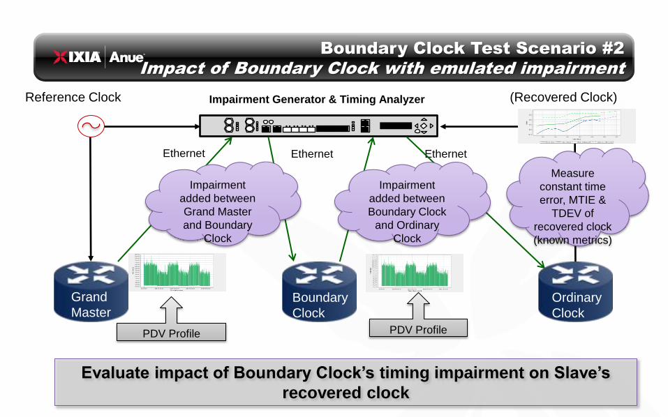
Boundary Clock Test Scenario #2
Impact of Boundary Clock with emulated impairment
Grand
Master Boundary
Clock
Ordinary
Clock
Impairment Generator & Timing Analyzer
Impairment
added between
Grand Master
and Boundary
Clock
Reference Clock (Recovered Clock)
Impairment
added between
Boundary Clock
and Ordinary
Clock
PDV Profile PDV Profile
Evaluate impact of Boundary Clock’s timing impairment on Slave’s
recovered clock
Measure
constant time
error, MTIE &
TDEV of
recovered clock
(known metrics)

Examples of Boundary Clock Impairment
Experiments on a real-world engineering prototype • The time error represented here indicates the difference between the
time-stamp and the actual measured arrival time of the packet (time-
stamp error)
Changes in this impairment were observed when the
conditions changed
• Changing the sync packet rate from the Grand Master to the BC’s
slave port, or from the BC’s master port to the slave
• Adding background traffic to the Boundary Clock under test
• Adding time error (impairment) from the Grand Master to the
BC’s slave port

Boundary Clock Impairment – BC #1
No background traffic, no impairments
• Grand Master sync rate 4pps
• Boundary clock master-port sync rate 16pps
• Substantial time error observed during 5-minute window

Boundary Clock Impairment – BC #1
No background traffic, no impairments
• Grand Master sync rate 8pps
• Boundary Clock master-port sync rate 8pps
• Dramatic change in behavior compared to other sync rate

Boundary Clock Impairment – BC #2
no background traffic, no impairments
• Grand Master sync rate 8pps
• Boundary Clock master-port sync rate 8pps
• A different device has dramatically different results
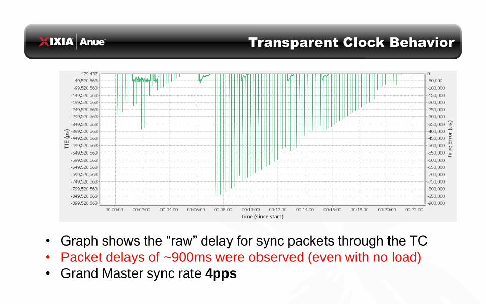
Transparent Clock Behavior
• Graph shows the “raw” delay for sync packets through the TC
• Packet delays of ~900ms were observed (even with no load)
• Grand Master sync rate 4pps

Transparent Clock Behavior
• Graph shows the corrected delay for the sync packets
• Packet delay variation reduced to ~24ns; delay error to ~2.7 s
• TC measurement granularity of 8ns is visible
• Note: this behavior was observed to be load independent

Measuring instrument Granularity
• The TC correction quantization is ~8ns
• Observation of this granularity requires test device to measure with a
precision of much better than ~4ns
• The measurement granularity of the test equipment is seen to be ~1ns
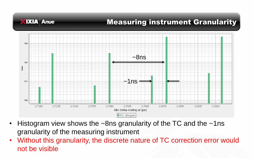
Measuring instrument Granularity
• Histogram view shows the ~8ns granularity of the TC and the ~1ns
granularity of the measuring instrument
• Without this granularity, the discrete nature of TC correction error would
not be visible
~8ns
~1ns

Boundary Clock Challenges
Inaccurate Clocks
Boundary Clocks Introduce Impairments
• Internal Clock
An internal clock is derived from the PTP on the slave port of the BC in the
usual manner and this local clock is used to create time-stamps on outgoing
PTP traffic
Inaccuracy in this clock creates impairment:
• Inaccurate time-stamps going out the master port; time-stamp does not accurately
indicate the true real time
any errors result directly in inaccuracy in the downstream clock
recovery
• System (PHY) clock
The system clock or PHY clock may be asynchronous with respect to this
internal PTP-derived clock
• Any difference in these two clocks results directly in inaccurate time-stamps, even if
the PTP internal clock is perfect

Boundary Clock Challenges
Not Ordinary Switches
Many boundary clocks are multi-function devices with many features not
related to timing that compete for resources with PTP
• L2 features such as spanning tree, VPNs, redundancy, VLANs, etc.
• QoS – L2 & L3, different egress and ingress, marking, priority, etc.
• Routing, Switch Virtual Interfaces, Routing Protocols, VRFs, MPLS
Architecture of these devices may not be ideal for PTP
• Designed primarily for fast switching of packets from port to port
• Limited emphasis on speed, latency, etc. of CPU-generated or control-plane
traffic
These caveats of Boundary Clocks are important to characterize
• They may not typically perform like a standard L2 switch with respect to PDV
• They may have significant impact on the performance of PTP networks
A boundary clock cannot simply be treated as if it were an ordinary switch
for testing purposes

Testing Questions Remain
Important questions remain regarding BC/TC testing
• What limits or metrics are applicable for impairment introduced by a
boundary clock as in Test Scenario #1?
TIE / PDV? Maximum Time Error? What limit is to be expected?
Will require both: constant time error (“static”), as well as TIE/PDV (“dynamic”)
• What PDV impairment profiles apply to test with impairments before and
after the Boundary Clock as in Test Scenario #2?
Does some model apply which emulates N number of Boundary Clocks, or
networks combining Boundary Clocks with ordinary switches?
• What is the precision/accuracy required in the test equipment?
Rule-of-thumb: at least one order of magnitude better than the same function
in the DUT (e.g. time-stamping)
Test signal generation (e.g. introduction of wander):

Testing Challenges
Boundary Clock as Slave or Master
Testing Boundary Clock as a slave or ordinary clock
• ITU-T Rec. require that T-BCs have a 1pps test port
• The standard G.8261 tests are performed without regard for the Boundary Clock’s
master port behavior, therefore do not address the purpose of the boundary clock
• This test does not address the time impairment introduced by circuitry between
the boundary clock’s slave and master ports
Testing Boundary Clocks as a master clock
• The standard G.8261 tests are performed with PDV impairment is added between
Boundary Clock and slave. Slave’s recovered clock interface is evaluated against
the standard MTIE/TDEV masks
• This test does not address the ability of the Boundary Clock to recover an
accurate clock in the presence of time error between the BC and the GM
• The Boundary Clock is not being measured directly; the result is dependent on
the performance of the slave device

Boundary/Transparent Clock Testing
Suggested Best Practices
Monitoring/measuring time error on both sides of a boundary/transparent clock
• Comparison between input and output reveals the static and dynamic impact of
the device and we can verify whether it is affected by
Background traffic, incoming and outgoing sync packet interval, QoS, routing, etc
Impairment on both sides of a boundary/transparent clock
• Impairment is added between the GM Clock and BC/TC, and between the
BC/TC and slave clock, simultaneously; recovered clock at remote slave is
measured
Profiles need to be developed
Measure ToD error and phase (1PPS) error introduced by boundary clocks
• Monitor and measure timestamp accuracy of sync, follow-up packets from
master port of boundary clock and measure phase offset of 1PPS between GM
Clock and Slave with boundary clock in between