Testing Machines and Systems for Composites · Compression tests Compression, OHC, FHC 8...
40
Testing Machines and Systems for Composites BB 824.2.0220 Intelligent Testing
Transcript of Testing Machines and Systems for Composites · Compression tests Compression, OHC, FHC 8...

Testing Machines and Systems for Composites
BB
824
.2.0
220
Intelligent Testing

2
Testing Applications for Fiber-Reinforced Composites
Application Variation Page
Testing applications overview 5
Tensile tests Tensile, OHT, FHT 6
Compression tests Compression, OHC, FHC 8
Compression after impact CAI 10
Shear tests IPS, V-notched shear, rail-shear, lap-shear, ILSS 11
Flexure tests 3-point, 4-point 15
Energy release rate GIc, GIIc, Mixed Mode 16
Pin-bearing strength Single shear tension, double shear tension 17
Products and Services for Composites Testing
Products Type Page
Electromechanical testing machines Table-top and floor-standing models 18
High-capacity machines Nominal loads between 300 kN and 1200 kN 20
Temperature chambers 21
Modular testing system for composites Temperature range of -70 °C to +250 °C 22
Fatigue testing machines Servohydraulic and electrodynamic 24
Automation Robotic testing systems for composites applications 25
Testing instruments Drop weight testers 26
Load cells 27
Testing software testXpert III 28
Extensometers Contact and non-contact measuring systems 30
Exact alignment of the testing machine Alignment 33
ZwickRoell Service 34
The ZwickRoell Group
Contents Page
The ZwickRoell Group 3
Your partner for composites testing 4
Standards Overview
Standards Page
Calibration, conditioning, specimen production 37
Long-fiber-reinforced composites 37
Sandwich, core and honeycomb type composites 38

3
ZwickRoell — Passion and expertise
Our company philosophy is found-ed on a passionate commitment to our customers. We work hard to ensure customer satisfaction by having over a third of our employ-ees engaged in service and sup-port.
As a family-owned company with a tradition dating back 150 years, we place great value on honesty and fairness. Over the years an ethos of close collaboration based on mutu-al trust between our partners, sup-pliers and customers has evolved, something that we all value highly.
Global Loops statue at the ZwickRoell headquarters in Ulm, Germany
The
Zw
ickR
oel
l Gro
upTe
stin
g a
pp
licat
ions
Pro
duc
ts /
ser
vice
sS
tand
ard
s
Always at your serviceOver 1100 people are employed at our headquarters in Ulm, Germany. Many of them have been with us for years — decades even. Their knowledge, ability and commit-ment are what lies behind the global success of the ZwickRoell Group.
We are present in over 50 countries around the world.
The right solutionsWhether for static materials testing or the various forms of fatigue testing —we have the right solutions. We offer products for hardness testing as well as instruments for impact testing and for melt index determination.
And for that rare occasion where we don’t have a ready-made solution to suit your needs, our experts will find the right solution for you, from the smallest adaptation to a fully automated testing system or a test stand for special purposes.
The foundation for a successful partnership: innovative employees as well as innovative products

4
Fig. 1: ZwickRoell products characterize composite materials in all normal and shear directions.
ZwickRoell — your partner for composites testing
System-based testing solutionsOver the last few years, experience and commitment have enabled ZwickRoell to develop the most comprehensive composites testing system worldwide. Despite of the complexity involved, the modular design of the test equipment com-bines ease of operation with a wide range of reconfiguration options for different types of tests. This allows you to attain reliable test results and perfectly accurate measurements that you can trust.
Another benefit of the modularity: our testing machines can be easily retrofitted for new test types for years to come.
Experts and standardsZwickRoell has around 100 employ-ees engaged in developing testing machines, instruments and software packages in line with the require-ments of modern standards.
Specialists in our Applications Test-ing Laboratories test new products and perform testing services for our customers to help validate the suit-ability for the required test types.
Through the participation of approx-imately ten employees in various standards committees, including those relating to testing machines, aerospace, plastics and fiber-rein-forced composites, ZwickRoell is closely involved in the development of standards at both the national and international level.
Fig. 2: ZwickRoell products meet all current standards.
Product qualityOur testing machines used to test brittle materials are subject to stringent requirements with regard to quality of the drive and guide components, their axiality, absence of play and, in the case of compres-sion tests also their stiffness. We meet these requirements by using high quality standard components, by making careful materials selec-tions and by implementing well-thought-out design principles.
Modern production methods, experienced employeesOur testing machines are produced using the latest manufacturing methods in a 7000 m² production area at the ZwickRoell headquarters in Ulm, Germany. Modern machin-ery plus assembly by a competent, highly experienced workforce en-sures consistent high quality. Many of our employees have been with the company for years, with some being second or third generations at ZwickRoell.
Calibration and alignment - a lot depends on itBefore being delivered, all test equipment is calibrated by Zwick-Roell according to current ISO standards. This ensures that all sen-sors measure correctly. For testing machines that are used for testing of brittle materials such as unidirec-tional fiber reinforced composites, ceramics or brittle metals, an align-ment measurement and adjustment can be performed.

5
Testing of fiber-reinforced composites
Fiber-reinforced composites exhibit orthotropic behavior and substan-tial elasticity in their range of use. Therefore, measurement of the stress-strain behavior in all normal and shear directions is common.
Standardization has developed a series of methods that characterize composite materials under a wide variety of load conditions.
Performing these tests requires precise tools and exact force ap-plication with excellent alignment, achieved by means of special align-ment fixtures.
Fig. 1: ZwickRoell offers the ideal machine configuration for every test. Two test areas, one on top of the other, or the option of additional side
test areas eliminate the need for modifications.
The
Zw
ickR
oel
l Gro
upTe
stin
g a
pp
licat
ions
Pro
duc
ts /
ser
vice
sS
tand
ard
s

6
Tensile testing on fibers and filament strands
Tensile tests on unidirectionally rein-forced materials, such as pultruded rods or resin coated filament bun-dles require a great deal of experi-ence in the selection of the suitable specimen grips.
In many cases the specimen must be protected with cap strips to avoid premature fiber breakage in the gripping area. However, there are solutions that eliminate the need for the cap strips and the cost and effort involved in the associated specimen preparation, leading to a true improvement in efficiency.
ZwickRoell offers a very wide se-lection of specimen grips and jaw inserts. Pre-testing is performed on customer specimens in ZwickRoell’s Applications Testing Laboratory to determine the optimal machine con-figuration.
Fig. 2: testXpert III ensures the correct test sequence — fully automated.
Fig. 1: Pultruded GFRP round specimen, gripped without cap strips. Right: Valid fiber breakage in the range of the free grip-to-grip separation through soft gripping force application.
Fig. 4: Testing of resin coated carbon fiber filament strand.
Fig. 3: Individual filaments are gripped inside paper frames.
Str
ess
in M
Pa
Elongation in %

7
Tensile tests and notch tensile tests on laminates
Tensile tests on unidirectional lam-inates require perfect alignment of the testing machine, suitable spec-imen grips and accurate extension measurement.
Multi-directional laminates are often tested with larger specimen cross sections. Because of their progres-sive damage behavior they are less alignment-sensitive.
ZwickRoell offers solutions for many different requirements: simple me-chanical wedge grips, as well as flexible wedge screw and hydraulic grips with connection system for compression, flexure and shear de-vices.
For determination of the specimen extension, strain gauges, clip-on extensometers and convenient, as well as damage-resistant mechan-ical and optical extensometers are available.
Fig. 2: Tensile tests are performed in fiber direction (0°), perpendicular (90°) or for multidirec-tional laminates. For multidirectional laminates, open-hole-tension (OHT) and filled-hole-tension (FHT) are common as well.
Fig. 1: For testing of laminates, centrally closing wedge grips, side adjustable wedge screw grips, as well as hydraulic, parallel closing body-over-wedge grips with a wide selection of jaws, are available.
The
Zw
ickR
oel
l Gro
upTe
stin
g a
pp
licat
ions
Pro
duc
ts /
ser
vice
sS
tand
ard
s

8
Compression tests, OHC, FHC
Various types of compression tests, each with its own specific fixture, have been developed over the last five decades.
These fixtures are usually distin-guished by the type of compression loading employed.
End loading between two compres-sion platens is simplest as far as the fixture is concerned, but it requires a high level of accuracy in machin-ing the specimen ends. The method delivers reliable compression mod-ulus values, but often results in pre-mature failure and therefore in low measured compressive strengths.
Force application through clamping (shear loading) is ideal for the mea-surement of higher strengths. Older ASTM standards defined the Cel-anese compression fixture, which was very sensitive to variations in specimen thickness. The EN stan-dard solved this problem by using flat wedges in place of cones in the grips.
The HCCF manufactured by Zwick-Roell represents a significant im-provement. The parallel hydraulic gripping principle prevents jaw movements during the test, result-ing in a higher proportion of valid tests. The HCCF can be used for shear loading at lower forces and in combined shear/end loading for high forces. It is also suitable for open and filled hole compression
tests (OHC, FHC) to the Airbus standard.
Alignment errors, which are most often caused by specimen prepa-ration, are visible before the actual load application and can be correct-ed.
In 2011 the HCCF was approved by Airbus for tests to AITM 1.0008.
Fig. 2: End loading compression fixture to prEN 2850 and ASTM D695 (Boeing modified). The support block is centered to the compression axis using stops.
Fig. 1: Manual IITRI compression fixture to ASTM D3410: specimens and wedge jaws are mounted in an adjustment device and aligned, and tested in a guided tool.
Fig. 3: Manual combined loading compres-sion fixture to ASTM D6641 (© Wyoming Test Fixtures, Inc.)

9
Open hole compression (OHC) and filled hole compression (FHC) tests to ASTM and Boeing standards are carried out on long specimens using anti-buckling supports.
ZwickRoell offers reliable strain measurement via strain gauges, as well as double-sided clip-on extensometers, which are perfectly guided between the HCCF clamp-ing jaws.
Fig. 5: OHC and FHC compression tests to ASTM require an anti-buckling support, which is used for shear loading with hydraulic specimen grips, and with end loading between compres-sion platens.
Fig. 2: The HCCF is also suitable for OHC and FHC.
Fig. 4: testXpert III stress-strain diagram with monitoring of relative bending
Fig. 3: The HCCF, Hydraulic Composites Compression Fixture, is used for shear loading and combined loading compression tests.
Fig. 1: Significantly improved bending and re-duced measured value scatter with the HCCF.
Fig. 6: Various standards allow for the use of clip-on extensometers.
The
Zw
ickR
oel
l Gro
upTe
stin
g a
pp
licat
ions
Pro
duc
ts /
ser
vice
sS
tand
ard
s
Rel
ativ
e be
ndin
g in
%
Fixture type: Celanese HCCF
prEN 2850 Celanese compression fixture versus HCCF. Relative bending determined at 10 % Fmax. Average and scatter.
Ben
ding
in %
Average compression in %
Com
pres
sion
str
ess
in M
Pa

10
Compression after impact (CAI)
For a CAI test the compressive re-sidual strength of a laminate after impact damage is determined. With this test, conclusions are drawn about the damage tolerance of a multidirectional composite lam-inate.
The instrumented drop weight tester HIT 230F with its adjustable drop height up to 1 m and the integrated speed measurement on the point of impact is in exact agreement with the requirements for pre-damaging of CAI specimens.
The modular weight set allows for accurate setting of the damage en-ergy. A special setup avoids multiple impacts. The impactor (16 mm di-ameter) is instrumented and gener-ates a force-travel diagram through the convenient testXpert III testing software, which provides indications of the damage progression.
In the subsequent compression test, the compressive residual force is determined. For ISO, EN and Airbus standards the specimen is gripped at the top and the bottom in the compression fixture, while for ASTM, DIN and Boeing standards it is only guided.
Strain gauges are applied to moni-tor bending and buckling.
Fig. 1: HIT 230F drop weight tester with accessories for CAI pre-damaging
Fig. 2: During the compression test, the compressive residual strength of the specimen, and with that its damage tolerance, is determined. (Bottom: compression fixture to ASTM, DIN, Boeing; top: compression fixture to ISO, EN, Airbus.)
Fig. 3: Secure mounting of the CAI specimen in the drop weight tester
Fig. 4: The instrumentation produces a force-travel-speed diagram.
Spe
ed in
m/s
Forc
e in
kN
Indentation in mm

11
In-plane shear (IPS), ± 45° tensile test
In this shear test, the fiber direction is ± 45° to the tensile axis of the specimen.
In a tensile test the fibers can slide against each other, causing defor-mation of the matrix.
The shear strain is determined from the longitudinal and transverse strain of the specimen. For this, ZwickRoell offers several solutions:
• Measurement with two strain gauges• Measurement with biaxial clip-on extensometer• Measurement with automatic makroXtens extensometer and additional transverse strain extensometer • Measurement with biaxial videoextensometer
testXpert III displays the shear stress/shear strain curve accord-ing to the standard and calculates characteristic values including shear modulus (G12) and shear strength (τ12M).
Fig. 1: The shear modulus is determined between two shear strains, e.g. 0.1 % and 0.5 % to ISO 14129 or 0.05 % and 0.25 % to prEN 6031 and AITM.
Fig. 2: The ± 45° laminate structure allows for the measurement of shear properties.
Fig. 3: Measurement of shear strain with strain gauges
Fig. 4: Measurement of shear strain with biaxial clip-on extensometer
Fig. 5: Measurement of shear strain in two planes with the makroXtens
The
Zw
ickR
oel
l Gro
upTe
stin
g a
pp
licat
ions
Pro
duc
ts /
ser
vice
sS
tand
ard
s
She
ar s
tres
s in
MP
a
Shear strain
In-plane shear modulus, GI2: 4400 MPa
In-plane shear strength, TI2M: 86.5 MPa
Tensile force at failure, Fm: 4790 N
Specimen thickness, h: 1.09 mm
Specimen width, b: 25.41 mm

12
V-notch shear test
With the V-notch shear test, shear properties of laminates made of unidirectional fiber composites, woven or braided fabrics can be determined.
There are two methods that are differentiated based on the size of the specimen and the type of load application. For the V-notch shear test to ASTM D7078 the specimen for the evaluation of coarser fiber architectures is larger and is gripped on the specimen surface. For the Iosipescu method to ASTM D5379 the load is introduced by clamping the specimen edges.
The notch ensures concentration of the shear stresses in the smallest cross section.
Shear strain is measured in this shear plane, for example usingstrain gauges with short grid lengths.
A fixture with manual gripping via screws is available for the V-notch method to ASTM D7078.
The Iosipescu method includes axial guidance of the specimen holders, providing a shear plane virtually free of bending moments.
The double guide on one part of the fixture facilitates the installation of the specimen and prevents an out-of-plane deformation of the speci-men during the test.
Fig. 1: Iosipescu method for the V-notch shear test. testXpert III provides accurate determination of shear stresses, shear strain and individual characteristic values.
Fig. 2: V-notch shear fixtures to ASTM D7078 with manual clamping (left) and stops for specimen alignment (right)
She
ar s
tres
s in
MP
a
Shear strain in
Shear modulus, G 2.98 GPa
Limit load, Pu 2.12 kN
End strength, Fu 42.0 MPa
Shear strain at limit load, ya 14702
Specimen thickness, h 4.03 mm
Specimen width, w 12.6 mm

13
The
Zw
ickR
oel
l Gro
upTe
stin
g a
pp
licat
ions
Pro
duc
ts /
ser
vice
sS
tand
ard
s
Rail shear method
ASTM provides additional methods for in-plane shear testing on unidi-rectional laminates and wovens, for which the test plates are mounted on rails.
The measurement values include shear stress and strength, shear strain, which is determined with strain gauges, as well as the shear modulus.
Shearing through overlapping (lap-shear)
This test method is commonly used for measurement comparison of the shear strength of adhesions or be-tween laminate planes.
With the use of a high-resolution extensometer, the shear strain can also be measured if the adhesive layer thickness is known.
Correct test results are achieved with exact alignment of the speci-men grips, which operate mechan-ically, pneumatically or hydraulically. Side adjustment of the jaws is required for simple single lap spec-imens.
Single lap shear specimen Double lap shear specimenSimple SimpleSlotted Slotted
Fig. 2: Shear tests through overlapping are performed with single or double lap shear speci-mens, in simple or slotted version.
Fig. 3: For testing of simple single lap shear specimens (left), the specimen grip must have a side adjustment; right: slotted specimen.
Fig. 1: Rail shear method to ASTM D4255, two-rail shear in tensile test (left), three-rail shear in tensile or compression test (right)

14
Interlaminar shear strength (ILSS) using the short-beam shear method (SBS)
In this test the distance of the sup-ports in relation to the specimen thickness is small. As a result the specimen is subjected to a shear load and broken.
The ILSS test fixture is intended for use in a wide temperature range.
Supports and dies can be set at an exact parallel. A lateral support bracket ensures exact maintenance in the center position.
Measurement surfaces on the inner sides of the supports allow for exact monitoring of the support span.
Various adjustment gauges and lead screw settings, as well as a height setting of the upper anvil are avail-able for testing of varying specimen thicknesses.
Fig. 2: ILSS fixture: A laterally guided upper anvil ensures exact central force application on the specimen. The support span is set manually or through centered lead screw adjustment.
Fig. 1: Support and die are exactly parallel. Centering stops make operation easy.
Fig. 4: Adjustment gauge with variable support span
Fig. 5: Attachment of a temperature sensor close to the specimen
Fig. 3: Standard 10 mm adjustment gauge for exact alignment
h = specimen thickness
Standard Die Radius, R Support Radius, r Span, L Centering Accuracy

15
Flexure tests
Three-point and 4-point flexure tests are performed with support spans of 16 to 40 times the spec-imen thickness. This keeps the shear portion sufficiently low.
The measured flexure moduli and strengths are strongly influenced by the laminate structure and there-fore do not correlate with the mea-sured tensile properties.
Deflections are generally determined using a displacement transducer placed at the mid-span below the specimen.
However, ZwickRoell testing ma-chines are additionally equipped with a highly accurate deformation compensation system, which in the case of 3-point flexure tests often allows for a sufficiently accurate de-
flection measurement with the inte-grated crosshead travel monitor.
The flexure test kits can be used over a wide temperature range, between -80 °C and +250 °C.
Fig. 2: 3-point flexure test with indirect dis-placement measurement via crosshead travel
Fig. 4: 4-point flexure test with direct displacement measurement
Fig. 1: Exact positioning of the specimen with the use of stops
Fig. 3: Die and supports are clamped under load and aligned with the adjustment gauge.
Fig. 5: Adjustment gauge for the 4-point flexure test arrangement
The
Zw
ickR
oel
l Gro
upTe
stin
g a
pp
licat
ions
Pro
duc
ts /
ser
vice
sS
tand
ard
s
Standard Method Specimen Thickness, h Die Radius, R Support Radius, r
3-point
4-point
3-point3-point3-point

16
Interlaminar energy release rate (G)
When measuring the critical energy release rate (Gc) the energy per crack area required to prop-agate a crack by a known path is determined.
Mode I — crack opening — is usu-ally measured in a DCB (double cantilever beam) arrangement and is described in many standards.
Mode II — in-plane shear — is frequently measured by the ENF (end notch flexure) method, using a 3-point or, less commonly, 4-point flexure method. The ISO standard applies the C-ELS (calibrated end loaded split) method. Less common is the TCT (transverse crack ten-sion) method.
The mixed mode I/II bending (MMB) method allows for the setting of defined mode proportions and simulates the superimposed loads, which occur frequently in practice.
Fig. 1: Mode II energy release rate GIIC Fig. 3: Adjustable Mode I / Mode II propor-tions
Fig. 4: The crack tip is followed with a magnify-ing glass.
Fig. 2: Mode I energy release rate (GIC) in a double cantilever beam (DCB) arrangement. Tracking of the crack tip with video recording delivers a film sequence synchronized with the force-displacement curve.
Forc
e in
N
crack opening in mm
17
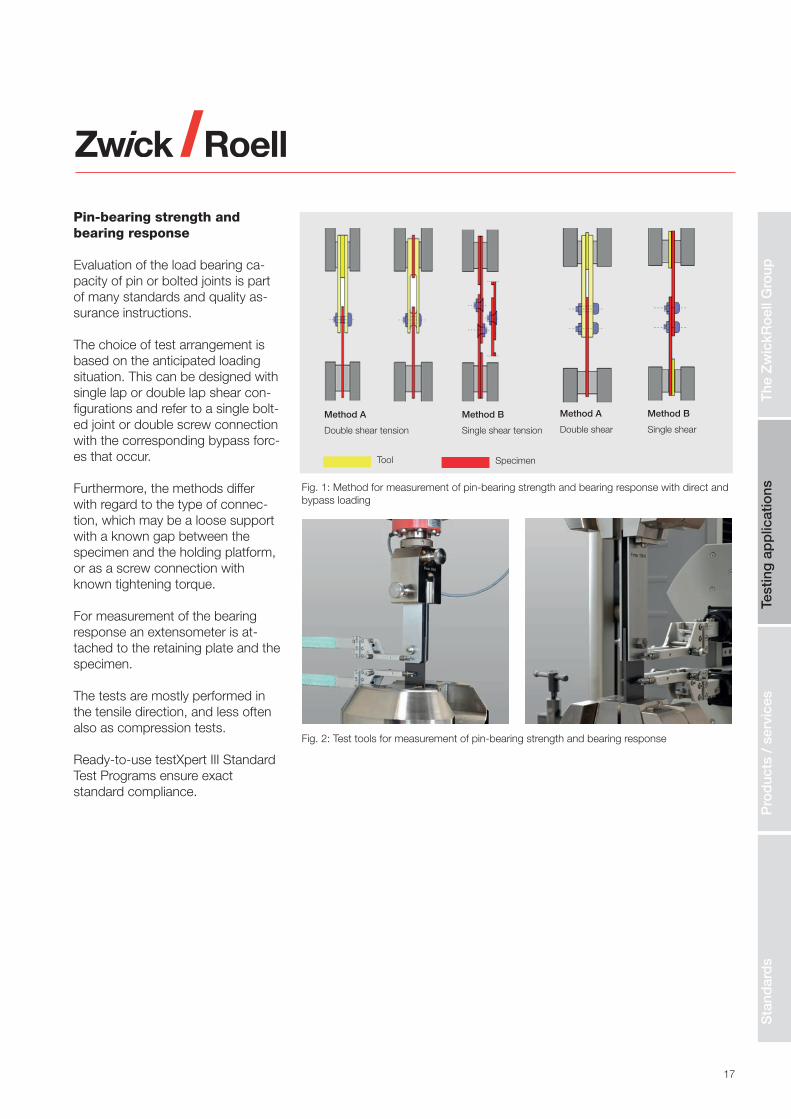
Pin-bearing strength and bearing response
Evaluation of the load bearing ca-pacity of pin or bolted joints is part of many standards and quality as-surance instructions.
The choice of test arrangement is based on the anticipated loading situation. This can be designed with single lap or double lap shear con-figurations and refer to a single bolt-ed joint or double screw connection with the corresponding bypass forc-es that occur.
Furthermore, the methods differ with regard to the type of connec-tion, which may be a loose support with a known gap between the specimen and the holding platform, or as a screw connection with known tightening torque.
For measurement of the bearing response an extensometer is at-tached to the retaining plate and the specimen.
The tests are mostly performed in the tensile direction, and less often also as compression tests.
Ready-to-use testXpert III StandardTest Programs ensure exact standard compliance.
Method A
Double shear tension
Method B
Single shear tension
Method A
Double shear
Method B
Single shear
Fig. 1: Method for measurement of pin-bearing strength and bearing response with direct and bypass loading
Tool Specimen
The
Zw
ickR
oel
l Gro
upTe
stin
g a
pp
licat
ions
Pro
duc
ts /
ser
vice
sS
tand
ard
s
Fig. 2: Test tools for measurement of pin-bearing strength and bearing response

18
Electromechanical testing machines
zwickiLineThese high-quality, easy to operate single-column load frames were designed for mechanical tests with test loads up to 5 kN.
In composites testing laboratories they are often used as an auxiliary machine for larger load frames to avoid having to reconfigure the latter for tests such as flexure, shear and GIC-, GIIC- tests.
ProLine series for standard test tasksMany standard types of tests involv-ing tensile, compression, shear or peel loads do not require expensive sensor equipment. In such cases a ProLine testing machine may be the optimal choice.
Table-top models — AllroundLineVarious table-top models are avail-able for standard tests in a force range up to 150 kN. They are equipped with two columns con-structed of patented extruded alu-minum profiles.
They are light, flexurally stiff and function as both lead screw guide and guard. The AllroundLine ta-ble-top models can be provided with support legs to enable the test area to be positioned at the opti-mum height for the operator or the application. This allows for the ma-chine to be operated conveniently from a seated position with com-pletely free leg space, making the system well suited for operation by wheelchair users.

19
Floor-standing models — AllroundLineFloor-standing models with electro-mechanical drives are available in a load range from 100 kN to 1200 kN and are used for tests on material specimens or structural compo-nents. Test types include tensile, compression and flexure tests, shear tests and torsion tests.
Extremely stiff load frame construc-tion with two or four guide columns ensures optimum conditions for ac-curate alignment of the test axes. The load frames can be equipped
with one or more test areas. Models with side test areas minimize the re-configuration efforts, since the tools for different test types stay in the machine.
For components testing the lower crosshead can be supplied as a mounting platform. For torsion tests the load frame is equipped with a torsion drive with testControl II and corresponding sensors. The AllroundLine floor-standing models therefore form a high-quality and flexible testing system for testing of composite materials.
testControl II — measurement and control electronicstestControl II is “Made by ZwickRo-ell” and optimally equipped for the requirements of composite materials testing. The measured values from the sensors are scanned at a rate of 400 kHz and then further processed at 2000 Hz. Combined with 24 bit signal resolution, this achieves op-timal signal quality over the entire speed range. T
he Z
wic
kRo
ell G
roup
Test
ing
ap
plic
atio
nsP
rod
ucts
/ s
ervi
ces
Sta
ndar
ds

20
High-capacity machines
The high laminate strength of fiber composites requires specimens that are adapted in regards to their dimensions. Very high forces are especially prominent in tensile, com-pression and CAI tests.
Electromechanical high-capacity machines of the Allround series with nominal loads between 300 kN and 1200 kN allow for testing with high, but also very low forces. The mod-ular fixture arrangement makes it easy and convenient to switch tools for the various test types.
Temperature chambers that can be moved out allow for testing in a wide range of temperatures.
A safety housing with an electrically interlocked safety door ensures the safety of the operator.
Exact alignment of the load string is ensured with the use of an align-ment fixture.
Fig. 1: High-capacity machine Z600

21
The
Zw
ickR
oel
l Gro
upTe
stin
g a
pp
licat
ions
Pro
duc
ts /
ser
vice
sS
tand
ard
s
Temperature chambers
Temperature chambers that can be conveniently driven into the test area on a guide rail are used for testing at both low and high tem-peratures. ZwickRoell temperature chambers provide the highest level of integration with the testing sys-tem and therefore ensure safe and reliable operation.
• Best temperature accuracy and distribution
• Temperature measurement near specimen and exact control
• Easy insertion of the specimen with the innovative door-in-door technology
• Time savings through precon-ditioning of the specimen in an interim magazine
• Exact positioning of the speci-men with mechanical insertion aids
• Optional side slots or panes with optical glass for the use of side mounted mechanical or non-contact extensometers
• Cable ducts for clip-on extensometers
• Front door with electrical inter-locking and safety door function
• Full integration with testXpert III for temperature control, vari-able fan speed, recording of the temperature during the test and switching on the internal lighting.
Fig. 1: The temperature chamber system is fully integrated in the testing machine. It provides a number of benefits that make the test safe and efficient.
Full integration and control of the temperature chamber in testXpert III
Door-in-door access
Interim magazine for specimen preconditioning in the temperature chamber
Near-specimen temperature measurement

22
Testing in a temperature rangeof -70 °C to +250 °C
Not
ch c
ompr
essi
on te
st (O
HC
, FH
C)
End
load
ing
com
pres
sion
test
She
ar lo
adin
g an
d co
mbi
ned
load
ing
com
pres
sion
test
with
the
HC
CF
Com
pres
sion
afte
r im
pact
(CA
I)
Tensile, notch tensile (OHT, FHT), bearing response, in-plane shear (IPS)
A modular concept for testing in temperature chambers
In aerospace applications, com-posites are routinely subjected to outside air temperatures of -55 °C, more than +200 °C in the area of the exhaust stream, and even high-er temperatures in the engines.
To reproduce these conditions during testing, temperature condi-tioning devices are available, which can be moved into the test area of the load frame on guide rails. The tools for the different tests can be connected to the existing hydraulic grips via mechanical adapters.
Variable load framesThe available installation area is op-timized at the lowest possible load frame height. Rigid flange connec-tion with the specimen grips ensure good lateral stability, also allowing for compression tests at higher loads. Provision is made for optional installation of an alignment fixture to ensure exact straightening of the test axis for alignment-sensitive tests.

23
Pro
duc
ts
Testing in a temperature rangeof -70 °C to +250 °C
Com
pres
sion
afte
r im
pact
(CA
I)
Testing at ambient temperature
Inte
rlam
inar
she
ar s
tren
gth
test
(ILS
S)
V-no
tch
shea
r te
st (I
osip
escu
)
V-no
tch
shea
r te
st (r
ail s
hear
)
GIIC
Ene
rgy
rele
ase
rate
(EN
F)
Mix
ed m
ode
bend
ing
(MM
B)
Flex
ure
test
(thr
ee-p
oint
, fou
r-po
int)
GIC E
nerg
y re
leas
e ra
te (D
CB
)
Iosi
pesc
u V-
notc
h sh
ear
test
at
low
forc
es
Lap
shea
r, in
-pla
ne s
hear
(IP
S),
90°
ten-
sile
test
at s
mal
l for
ces
21 types of tests, 115 standardsThe modular testing system covers all the important standard tests for fiber-reinforced composites: • Tensile tests• Notch tensile tests, OHT and FHT• In-plane shear tests, IPS• Interlaminar shear strength test, ILSS• Compression tests, CAI com- pression tests
• Notched compression tests, OHC and FHC• V-notch shear tests• Bearing response tests
Additional tests at ambient temperatureWithdrawing the temperature cham-ber allows for additional tests requir-ing a smaller load cell:
• Three-point and four-point flexure tests • Measurement of energy release rates GIC and GIIC
This modular system is available for electromechanical testing machines with load stages 100 kN, 250 kN and 600 kN, as well as for different servohydraulic testing machines for fatigue tests.
The
Zw
ickR
oel
l Gro
upTe
stin
g a
pp
licat
ions
Pro
duc
ts /
ser
vice
sS
tand
ard
s

24
Fig. 2: Servohydraulic testing machine type HB100 (left) and HC compact (right). Modular design for dynamic and static testing of composite materials.
Fig. 1: LTM 10 - fatigue testing for various test types in the load range
Fatigue testing machines
For dynamic cyclic testing of com-posites, testing machines with dif-ferent drive systems are used.
LTM testing machines with linear motor technology are manufactured in nominal load stages of 1 kN, 2 kN, 3 kN, 5 kN and 10 kN. The core piece is the patented electrody-namic drive specifically developed for testing technology. It allows for test frequencies up to 100 Hz and is able to exactly and reproducibly perform a wide variety of function sequences such as sinusoidal, tri-angular, rectangular and trapezoidal functions, as well as follow-up tests. The strongest feature of this drive is precise test performance at low operation and service costs. For operation of the LTM only a suitable power supply is required.
Servohydraulic testing machines are used for dynamic cyclic tests as well as static tests. The standard frequency range reaches up to 100 Hz, at forces up to 2500 kN. Com-mon load frames are manufactured with nominal load stages of 10 kN, 25 kN, 100 kN, 250 kN and 500 kN. The hydraulic power is either supplied by a power pack on the testing machine, or from a central hydraulic system. The compact series machines use an integrated low-noise power pack and allow for space-optimized operation in labo-ratories without central hydraulics. Both types of machine are equipped with force and piston displacement transducers and can be expanded with additional sensors, temperature chambers and safety devices, as well as various cooling principles.

25
Automation
Qualification of new composite systems requires a comprehensive testing campaign. ZwickRoell is a specialist for automation in testing technology and provides proven systems with exceptional features.
roboTest L—automationThis automated system operates with pneumatic vacuum grippers or claw grips. Up to 450 specimens are placed on a table in stacks or magazine compartments. The specimen cross-section can be measured during the automated se-quence, and an integrated barcode reader system is available for speci-men identification.
roboTest R—automationThis automated system is very use-ful if several testing machines are
integrated into a system, for appli-cations in a temperature condition-ing device and for tests that require special specimen handling.
Advantages:• Reliable test results:
Accurate—because all sensors are precisely calibrated Repeatable—because auto-mation ensures that all process-es are carried out exactly the same way Reproducible—because the test sequences follow standard requirements accurately, with-out deviations among operators Traceable—because every-thing is logged in detail
• Expanded capacity through un-manned testing overnight or on weekends
• Sorting of specimen remains• Documentation of failure types
Fig. 1: Fully automated testing system with two load frames for tensile, OHT, FHT, IPS, lap shear, ILSS, bearing response and flexure tests over a wide temperature range
Fig. 2: roboTest L automation
Fig. 3: roboTest R automation
Pro
duc
tsT
he Z
wic
kRo
ell G
roup
Test
ing
ap
plic
atio
nsP
rod
ucts
/ s
ervi
ces
Sta
ndar
ds
26
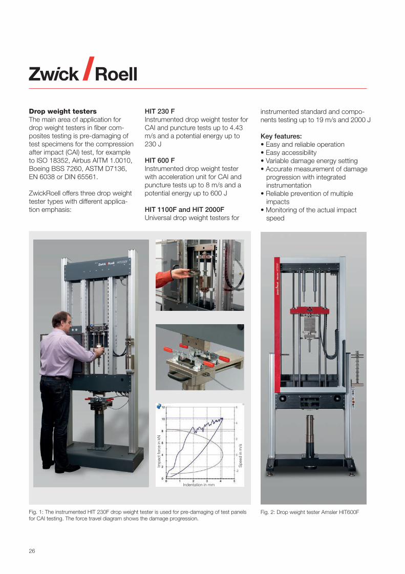
Drop weight testers The main area of application for drop weight testers in fiber com-posites testing is pre-damaging of test specimens for the compression after impact (CAI) test, for example to ISO 18352, Airbus AITM 1.0010, Boeing BSS 7260, ASTM D7136, EN 6038 or DIN 65561.
ZwickRoell offers three drop weight tester types with different applica-tion emphasis:
HIT 230 FInstrumented drop weight tester for CAI and puncture tests up to 4.43 m/s and a potential energy up to 230 J
HIT 600 FInstrumented drop weight tester with acceleration unit for CAI and puncture tests up to 8 m/s and a potential energy up to 600 J
HIT 1100F and HIT 2000FUniversal drop weight testers for
Fig. 1: The instrumented HIT 230F drop weight tester is used for pre-damaging of test panels for CAI testing. The force travel diagram shows the damage progression.
instrumented standard and compo-nents testing up to 19 m/s and 2000 J
Key features: • Easy and reliable operation• Easy accessibility• Variable damage energy setting• Accurate measurement of damage progression with integrated instrumentation• Reliable prevention of multiple impacts• Monitoring of the actual impact speed
Fig. 2: Drop weight tester Amsler HIT600F
Impa
ct fo
rce
in k
N
Indentation in mm
Spe
ed in
m/s

27
Load cellsLoad cells must satisfy the highest quality requirements.
The basis for this is a calibration to ISO 7500-1 or ASTM E4. This calibration is performed as a factory calibration, and can be repeated by our service technicians as a DAkkS, COFRAC or NAMAS calibrationafter the testing equipment has been commissioned. This way you can always rely on your testing ma-chine.
But ZwickRoell load cells can do much more:Automatic identification with inte-grated zero-point and sensitivity adjustment ensure that any load cell can be used with any testing machine without the need for a new calibration.
Temperature compensation makes measuring largely independent of the actual ambient temperature. This all takes place over a very wide
measuring range in which measure-ments are performed to accuracy class 0.5 or 1.
Xforce HP and Xforce K series load cells reach accuracy class 1, start-ing at 0.1% of the nominal load.
Fig. 2: Every load cell undergoes a ZwickRoell factory calibration as soon as it enters service on a testing machine.
Fig. 1: Load cells for the most demanding quality requirements. Installed Xforce HP series load cell (left). Various Xforce HP and P series load cells (right).
The
Zw
ickR
oel
l Gro
upTe
stin
g a
pp
licat
ions
Pro
duc
ts /
ser
vice
sS
tand
ard
s

28
testXpert III testing software
Intuitive and workflow-based from the very start.testXpert III is the result of close cooperation with software users in the materials testing industry and the experience of over 35,000 successful testXpert installations. From the very start, users can easily and intuitively navigate testXpert III. Meaningful icons and clear visual connections help the user, and reduce the number of mouse clicks required.
A workflow aligned to your operating processesThe software guides you through the various stages of a test, from preparing and running the test to analyzing results. • Set up testing system—config-
ure all machine-related settings for your testing application.
• Configure test—set all test-re-lated parameters, such as selecting results with the intelli-gent wizard.
• Run test—experience fast and easy navigation through the entire test sequence.
• View results—verify all test data, also in secure mode.
Intelligent user management means you can define different user roles or adopt user roles defined in the Win-dows accounts with LDAP. The user can focus on the task at hand right from the start and avoid input er-rors. testXpert III is workflow-based throughout, keeping training time to a minimum and enabling efficient, reliable testing. System Configuration Builder — a unique software conceptSystem Configuration Builder allows you to preset and save all relevant testing system and safety settings such as crosshead position, dis-tance between fixtures, or sensor
Fig. 1: Workflow based on the user's lab processes from an administrator view with full functionality - www.testXpert.com
Fig. 2: View optimized for the tester (left); the intelligent wizard for test configuration (right)

29
configuration in a freely definable system configuration. The saved system configuration checks the connected sensors. The test can only be started when the parame-ters match the preset requirements. This ensures exactly reproducible test conditions.
Tamper-proof test resultstestXpert III logs all testing system and system settings, ensuring traceable results. The traceability offered by testXpert III means you always have answers to the ques-tion: "When does who do what, why and who is responsible?"
testXpert III guarantees reliable test results and maximum security for users and the testing system.
Reliable import and exporttestXpert III can communicate di-rectly with any IT system. All test-re-lated data is imported quickly and directly from ERP systems, data-bases or directly from external de-vices. Data can easily be exported to all your usual evaluation/analysis platforms.
Standard-compliant testing testXpert III offers over 600 pre-pared Standard Test Programs, preconfigured to test standard requirements and with integrated results tables and statistics. You can begin standard-compliant testing immediately. testXpert III will take care of the rest.
Fig. 1: This means that saved test environments can be recreated following a change of test arrangement, so that tests can be performed using identical settings.
Fig. 3: Reliable and simple interfaces for sharing the test results
Fig. 2: Structured workflow with clear visual association of related content
The
Zw
ickR
oel
l Gro
upTe
stin
g a
pp
licat
ions
Pro
duc
ts /
ser
vice
sS
tand
ard
s

30
Precise strain and extension measurement Strain gauges are still widely used in the field of fiber-reinforced com-posites. They can be attached directly to the specimen or act as the measuring element in a clip-on extensometer.
The measurement signals are acquired precisely, directly and synchronously by ZwickRoell’s test-Control II measurement electronics.
Alternatively, measurement am-plifiers by HBM, e.g. the MGC or QuantumX are available, which are fully integrated in the ZwickRoell en-vironment in testXpert III.
Fig. 4: Direct connection of the strain gauges to testControl II via a ready-configured control box.
Fig. 1: The biaxial clip-on extensometer can be used at both high and low temperatures.
Fig. 2: Strain gauges are applied directly to the specimen.
Fig. 3: HBM measurement amplifiers are supported by testXpert III.
Fig. 5: Clip-on axial extensometer
Fig. 6: Clip-on transverse strain extensometer

31
Automatic extension measure-ment with makroXtens
Automatic extensometers using a mechanical or optical measuring principle simplify test preparation and performance.
The makroXtens employs mechan-ical measurement and is used for many types of tests. With a high measurement value resolution of up to 0.006 µm it satisfies the ad-ditional requirements for modulus measurement in tensile tests to ISO 527-1. Its swiveling knife edges pro-vide reliable protection up to speci-men break.
Fig. 1: Mechanical measurement, automatic attachment: makroXtens
Fig. 2: makroXtens with long feeler sensors for tensile testing in a temperature chamber
Fig. 4: makroXtens with transverse strain extensometer for tensile or in-plane shear (IPS) tests at RT
Fig. 3: makroXtens with flexure sensors for 3- and 4-point flexure tests
Fig. 5: makroXtens for module determination in an end loading compression test
The
Zw
ickR
oel
l Gro
upTe
stin
g a
pp
licat
ions
Pro
duc
ts /
ser
vice
sS
tand
ard
s

32
Non-contact extension measurement with videoXtens
ZwickRoell is a leader in non-con-tact measurement. While the videoXtens HP tracks the displace-ment of gauge marks via image analysis, the natural pattern on the specimen surface is enough for the videoXtens biax HP for opaque fiber-reinforced composites, to de-termine longitudinal and transverse strain without the need for addition-al markings.
The videoXtens HP and the videoXtens biax HP are ideal for tensile, in-plane shear (IPS) and flexure tests and can be used at ambient temperature, as well as the
entire temperature range of the tem-perature chamber.
Both instruments meet the strict re-quirements on strain measurement for determination of the Young’s modulus to ISO 527-1 Annex C.
With an additional camera for trans-verse strain measurement, material characteristics such as Poisson’s ratio and shear modulus can be determined with very high accuracy, using the videoXtens biax HP.
Through non-contact measurement the possibility of damage to the videoXtens, even at very high ener-gy failure modes, is eliminated. The strain measurement can therefore be carried out until specimen break.
Fig. 3: Non-contact strain measurement with videoXtens HP using gauge marks
Fig. 1: Non-contact strain measurement with videoXtens biax HP (left) using the natural pattern of the specimen surface (center) or with the use of gauge marks (right)
Fig. 2: Strain measurement without the use of gauge marks using the videoXtens HP in a in-plane shear (IPS) test. Natural surface pattern of the unidirectional CFRP material IPS specimen (left), shear stress/shear strain curve (center), determined longitudinal and transverse strain (right).

33
The
Zw
ickR
oel
l Gro
upTe
stin
g a
pp
licat
ions
Pro
duc
ts /
ser
vice
sS
tand
ard
s
A
B
C
α
α
x
Exact alignment of the testing machine
Testing machine alignment errors lead to the introduction of non-axial specimen deformations. Especially in the case of unidirectional rein-forced composite materials this can have significant influence on the test results.
ZwickRoell testing machines are precision manufactured, with guide components that satisfy the strictest quality requirements.
Exact axial alignment of specimen grips for alignment-sensitive fiber- reinforced composites, and elimina-tion of angular errors is achieved by accurate adjustment performed by means of an alignment fixture.
The result of these adjustments is checked with a precision alignment gauge, which satisfies the require-
ments of ASTM E1012, ISO 23788, and for the aerospace industry the Nadcap Audit Criteria AC7122.
ZwickRoell supplies the necessary
adjustment and measurement equipment, as well as alignment measurement as a service provided by experienced and well trained ser-vice technicians.
Fig. 2: Typical alignment errors: angle error (left), concentric offset error (right)
Fig. 1: Testing machine alignment and verification by a ZwickRoell technician using alignment in accordance with Nadcap AC 7122
Example: Brittle material
StrainOuter fiber
Measured average strain
StrainInner fiber
Alignment errors lead to elevated outer fiber strain and therefore toapparently lower resistance through premature specimen failure.
Mea
sure
d av
erag
e te
nsile
stre
ss
Local specimen strain,
PB = Percent bending, relative to the applied longitudinal strain
Inner fiber, point CMeasured, average strain, point BStrain of outer fiber, point A

34
Services
Laboratory for Materials and Components Testing
For companies with a testing requirement but no suitable testing option, ZwickRoell's Laboratory for Materials and Components Testing is ready to provide expert assis-tance.
We can also help out in the event of capacity bottlenecks or perform cross-validation tests. It makes no difference whether just a single test is involved or entire test series. With the latest technology and modern testing machines, we guarantee fast, standard-compliant testing. Naturally we can also perform tests in accordance with factory stan-dards.
Our Laboratories for Materials and Components Testing perform testing services of all kinds, on all static and dynamic materials testing machines. Hardness and extrusion tests, and torsion and temperature tests can be performed as well.
Our testing is individually tailored for a wide range of components and materials, whether metals, plastics, composites, rubber, or other — you're in good hands with us.
Contact: Tel. +49 7305 10-11440 [email protected]
Fig. 2: An excerpt of the dynamic testing machines in the ZwickRoell Materials and Components Testing Laboratory
Fig. 1: Static testing machines and instruments in the ZwickRoell testing laboratory
Fig. 3: Materials and Components Testing Laboratory

35
The
Zw
ickR
oel
l Gro
upTe
stin
g a
pp
licat
ions
Pro
duc
ts /
ser
vice
sS
tand
ard
s
Application technology
Our technical field consultants and experienced application engineers are here to provide you with expert consultation. Our qualified engineers will draw on their solid expertise to provide support during the planning and implementation of all or any testing applications.
Our Applications Testing Laborato-ries are equipped with permanent materials testing machine displays and instruments, including a com-prehensive portfolio of accessories such as specimen grips, test fix-tures, sensors, and temperature chambers.
Overview of services
Our service technicians guarantee successful and easy commissioning — from installation to initial calibra-tion to any training instructions.
Customer supportThe ZwickRoell Hotline is always available to support customers with questions regarding troubleshooting hardware and software.
Inspection and calibrationNaturally, we will also carry out the required annual inspection and calibration. Our checklist-based inspections and calibrations pro-vide a sound basis for reliable test results. They also extend the life of your materials testing machines and instruments, saving operating costs in the long term.
Fig. 2: ZwickRoell operates a DAkkS-accredited calibration laboratory. With over 10,000 calibrations performed annually, this is the largest calibration laboratory in Germany.
Fig. 1: Experienced application engineers will advise you on individually tailored testing options

36
Software servicesOnce you have purchased your testing software we are ready to provide additional software services upon your request — software trials, updates, customizations, training — whatever you need.
Training Courses at ZwickRoell AcademyOur ZwickRoell Academy offers a comprehensive, modular training program at ZwickRoell's headquar-ters in Ulm, at a ZwickRoell location near you, or directly on-site at your premises. This ranges from courses on our testing software, to applica-tions courses and workshops, to courses tailored to your company's individual requirements.
Other servicesIf you need to move your materi-als testing machine to a different location, ZwickRoell’s removal and relocation service will assist with technical and organizational planning, as well as transport and
full recommissioning. Professional and documented verification of the alignment of your testing machine using standardized alignment trans-ducers (referred to as alignment measurement) is a fundamental component of our service portfolio.
Fig. 1: ZwickRoell provides continuous support throughout the entire life-cycle of materials testing systems.
ACQUISITION
Consultation
Demonstration
Pre-testing
Consultation
Pre-acceptance
Installation
Machine instruction
Initial calibration
DQ/IQ/OQ
Modernization / Return /
New acquisition
COMMISSIONING MACHINE OPERATION
Hotline / Support Desk repairs
Spare parts
Software services
Training courses - ZwickRoell Academy
Testing laboratory / Contract testing
Maintenance / Inspection / Calibration
Retrofit / Machine relocation /
Alignment measurement / Measuring
system analysis
Fig. 2: The ZwickRoell Academy offers an interesting and wide-ranging training program for new students and advanced users alike.
Furthermore, we are able to perform logged measuring system analyses on testing machines and determine the corresponding characteristic capability values.

37
The
Zw
ickR
oel
l Gro
upTe
stin
g a
pp
licat
ions
Pro
duc
ts /
ser
vice
sS
tand
ard
s
Contents Standards Test fixture
Test fixtures and corresponding calibration
Tensile, compression and flexure testing machines DIN 51220, Airbus QVA-Z11-01-00, Airbus QVA-Z11-01-03
Impact testing machines ISO 13802, EN 10045-2, DIN 51230
Force calibration ISO 7500-1, -2, ASTM E4
Extensometer calibration ISO 9513, ISO 5893, ASTM E83
Alignment ASTM E1012, ISO 23788, Nadcap AC 7122/Annex A
Environmental conditions, conditioning
Humidity, moisture absorption ASTM D5229, EN 2489, EN 2823
Influence of test fluids EN 2489
Test temperatures EN 2744
Conditioning EN 2743, EN 2823, SACMA SRM 11
Production of specimens
Production of test plates ISO 1268, ISO 9353, EN 2374, EN 2565, EN 12576, DIN 65071
Mechanical processing ISO 2818
Application of strain gauges ASTM E1237
Long-fiber-reinforced composites
Testing of composite materials overview
Composite materials terminology
Tensile testing of textile glass
ASTM D4762, ISO 20144, ASTM D6856
ASTM D3878
ISO 3341, ISO 3342, ISO 3375 Materials testing machine
Tensile tests on single filaments and threads ISO 11566, ISO 10618 Materials testing machine
Tensile tests on filament strands ASTM D4018, ISO 9163 Materials testing machine
Tensile tests on pultruded rods ASTM D3916 Materials testing machine
Tensile tests on hoop wound cylinders ASTM D5450 Materials testing machine
Tensile tests on prepregs DIN 65469, DIN 29971 Materials testing machine
Tensile tests on laminates
Tensile tests on quilted connections
Properties in thickness orientation
ISO 527-1, -4, -5, ASTM D3039, ASTM D7565, ASTM D3552,
EN 2561, EN 2597, DIN 65378, AITM 1-0007, Airbus
QVA-Z10-46-34, Airbus QVA-Z10-46-36, AITM 1-0049, Boeing
BSS 7320, SACMA SRM 4R-94, SACMA SRM 9-94, TR 88012
CRAG Methods 300-303
AITM 1-0029
ISO 20975-1, -2, ASTM D7291
Materials testing machine
Materials testing machine
Materials testing machine
Shear tests on laminates ASTM D7291 Materials testing machine
Notch tensile tests, OHT, FHT ASTM D5766, ASTM 6742, AITM 1.0007, EN 6035,
AITM 1-0050, SACMA SRM 5-94, NASA RP 1092 ST-3
Materials testing machine
Determination of the Poisson's ratio ASTM E132, ISO 527-4, -5 Materials testing machine
Compression tests on pultruded rods ISO 3597-3 Materials testing machine
Compression tests on hoop wound cylinders
Compression test, sandwich beam
ASTM D5449
ASTM D5467
Materials testing machine
Materials testing machine
Compression tests, end loading ISO 14126 Method 2, ASTM D695, prEN 2850 B, DIN 65375,
JIS K7076, Boeing BSS 7260 - type III and IV, SACMA SRM 1R-94,
SACMA SRM 6-94, RAE-TR 88012 CRAG Methods 400 and 401
Materials testing machine
Compression tests, shear loading ISO 14126 Method 1, ASTM D3410, prEN 2850 A, JIS K7076, AITM
1-0008, Airbus QVA-Z10-46-38, RAE-TR 88012
CRAG Methods 400 and 401
Materials testing machine
Compression tests, combined loading ISO 14126 Method 2, ASTM D6641, ASTM C1358, AITM 1-0008 Materials testing machine
Notch compression tests, OHC, FHC ISO 12817, ASTM D6484, ASTM D6742, prEN 6036, AITM 1-0008,
Boeing BSS 7260 - Type 1, SACMA SRM 3R-94, NASA RP 1092
ST-4, RAE-TR 88012 CRAG Method 402, Northrop NAI-1504C
Materials testing machine
Compression residual strength after indentation ASTM D6264 Materials testing machine
Damage tolerance, CAI compression after impact ISO 18352, ASTM D7136, ASTM D7137, prEN 6038,
AITM 1.0010, Boeing BSS 7260 - type II, CRAG Method 403,
SACMA SRM 2R-94, DIN 65561, NASA RP 1092 ST-1
Drop weight tester & materials
testing machine

38
Contents Standards Test fixture
Tensile residual strength and compression residual
strength after edge impact
AITM 1-0076
Drop weight tester & materials
testing machine
Flexure tests on laminates ISO 14125, ASTM D790, ASTM D7264, EN 2562, EN 2746, TR
88012 CRAG Method 200, HSR/EPM-D-003-93
Materials testing machine
Flexure tests on pultruded profiles and rods
Flexure tests on curved sections
ISO 3597-2, ASTM D4476, EN 13706-2
ASTM D6415, AITM 1-0069
Materials testing machine
Materials testing machine
Short beam shear test, ILSS
Short beam shear test – double beam method
ISO 14130, ASTM D2344, EN 2377, EN 2563, JIS K7078, Airbus
QVA-Z10-46-10, AITM 1-0047, SACMA SRM 8-88, CRAG Method
100
ISO 19927
Materials testing machine
Materials testing machine
Short beam shear test on pultruded rods ISO 3597-4, ASTM D4475, Materials testing machine
In-plane shear with ± 45° tensile test, IPS ISO 14129, ASTM D3518, EN 6031, DIN 65466, JIS K7079, AITM
1-0002, Airbus QVA-Z10-46-22, SACMA SRM 7-94, RAE TR 88012
CRAG Method 101
Materials testing machine
In-plane shear (IPS) ISO 15310 Materials testing machine
In-plane shear, hoop wound cylinder ASTM D5448 Materials testing machine
Lap shear ASTM D3846, ASTM D3914, ASTM D7616, ASTM D5868,
EN 2243-1, EN 2243-6, EN 6060, DIN 65148, AITM 1.0019, Airbus
QVA-Z10-46-09, Airbus QVA-Z10-46-01, CRAG Method 102
Materials testing machine
Rail shear ASTM D4255 Materials testing machine
V-notch shear
In-plane shear, shear frame method
ASTM D5379, ASTM D7078
ISO 20337, DIN EN ISO 20337
Materials testing machine
Materials testing machine
Bearing response, fastener connections ISO 12815, ASTM D5961, ASTM D7248, EN 6037, DIN 65562,
AITM 1-0009, AITM 1-0051, AITM 1-0065, AITM1-0067, TR 88012
CRAG Method 700, SACMA SRM 9-89
Materials testing machine
Fastener pull-through resistance ASTM D7332, AITM 1-0066 Materials testing machine
Bearing response, pultruded profiles EN 13706-2 Materials testing machine
Energy release rates GIC
(DCB) ISO 15024, ASTM D5528, EN 6033, AITM 1-0005, AITM 1-0053,
Boeing BSS 7273, Boeing BMS 8-276, ESIS TC 4, NASA Method
RP 1092 ST-5
Materials testing machine
Energy release rates GIIC
(ENF) ASTM D7905, prEN 6034, AITM 1-0006, Materials testing machine
Energy release rates GIIC
(C-ELS) ISO 15114, AITM 1-0068 Materials testing machine
Energy release rates, Mixed mode GI/G
IIASTM D6671 Materials testing machine
Long life fatigue of laminates ISO 13003, ASTM D3479, AITM 1-0075, HSR/EPM-D-002-93 Servohydr. testing machine, LTM
Notch long life fatigue ASTM D7615 Servohydr. testing machine, LTM
Long life fatigue of fastener connections ASTM D6873, AITM 1-0074 Servohydr. testing machine, LTM
Mode I Fatigue delamination growth ASTM D6115 Servohydr. testing machine, LTM
Hardness testing ASTM D2583, EN 59 Barcol hardness tester
Heat deflection temperature HDT ISO 75-1, -3, ASTM D648 HDT testing instrument
Creep tests ASTM D7737 Creep testing machine
Impact strength, Izod ASTM D256, ISO 180 Pendulum impact tester
Impact strength, Charpy ISO 179-1, -2 Pendulum impact tester
Sandwich, core and honeycomb type composites
Tensile test perpendicular to the faces ASTM C297, ASTM D1623, EN 2243-4, DIN 53292, AITM 1-0025 Materials testing machine
Poisson's ratio of honeycomb core materials
Node tensile strength of honeycomb cores
Transverse contraction of honeycomb cores
ASTM D6790
ASTM C363, AITM 1-0061, Airbus QV-Z10-46-45 AITM 1-0062, Airbus QVA-Z10-46-46
Materials testing machine
Materials testing machine
Materials testing machine
Compression test perpendicular to the faces ASTM C365, ISO 844, DIN 53291 Materials testing machine
Compressive strength and modulus of fillers Airbus QVA-Z10-46-17 Materials testing machine

39
Energy absorption of honeycomb sandwich core
materials
ASTM D7336 Materials testing machine
Compression after impact, CAI on surfacing AITM 1-0077 Materials testing machine
Contents Standards Test fixture
Flexure tests ASTM C393, ASTM D6416, ASTM D7249, ASTM D7956,
DIN 53293, AITM 1-0018; Airbus QVA-Z10-46-31
Materials testing machine
Shear tests ASTM 273, ASTM D8067, DIN 53294, AITM 1-0030, AITM 1-0046,
AITM 1-0056, Airbus QVA-Z10-46-06
Materials testing machine
Flexural and shear stiffness test ASTM D7250
Climbing drum peel test ASTM D1781, DIN 53295, AITM 1-0080, Airbus QVA-Z10-46-05 Materials testing machine
Ciba peel test Airbus QVA-Z10-46-02 Materials testing machine
90° peel test (T-Peel) ASTM D1876 Materials testing machine
Floating roller peel (Bell) ASTM D3167, ISO 4578, Airbus QVA-Z10-46-03 Materials testing machine
Flexural creep test ASTM D480 Creep testing machine
Shear fatigue behavior ASTM C394 Servohydr. testing machine, LTM
Damage resistance ASTM D7766, AITM 1-0057 Drop weight tester
The
Zw
ickR
oel
l Gro
upTe
stin
g a
pp
licat
ions
Pro
duc
ts /
ser
vice
sS
tand
ard
s

ZwickRoellAugust-Nagel-Str. 11D-89079 UlmPhone +49 7305 10 - 0Fax +49 7305 10 - [email protected]
Find your local company – worldwidewww.zwickroell.com