Testing electro-optical measurement instruments
4
Alignment telescopes Parallelism of the Telescope line of sight with respect to the barrel of the Telescope is checked by sighting on the Variable Focus Collimator and revolving the Telescope through 180 degrees (see figure 1). The variable focus of the Collimator simulates all focal distances, enabling the straightness of the Telescope line of sight to be checked. The graduated scale target on the front of the Collimator is used for checking concentricity of the Telescope line of sight to the barrel and also linearity of the Telescope micrometers. The Test Wedge is used to measure the angle of parallelism. This test equipment can be used to also check non Taylor Hobson Telescopes. Details of quick field checks are in the Taylor Hobson Micro Alignment Handbook. The fixed test wedge (code 137-1940) This can be used to quickly check the accuracy of any autocollimator. It introduces a fixed angle of deviation nominally of 60 seconds by rotating the wedge from minimum to maximum deviation and comparing this with the readings on the autocollimator (see figure 4). Autocollimators The main calibration equipment used to check Autocollimators is the Small Angle Generator (TA48) 137-1918 – see fig 2. This is a lever (sine bar) system which is tilted through a known angle by either using a rotating drum or by raising the lever at one end using slip gauges. It consists of a beam which is pivoted at one end on rollers; the other end can be displaced a known amount by means of a large diameter micrometer drum, the anvil of which bears down vertically on a steel ball mounted on the base. The beam carries a reflector which can be mounted at two heights for autocollimator tests and a small bed with adjustable vees for checking bubble vials and electronic levels such as the Talyvel. Total Measuring Range: 200 Minutes of Arc Resolution: 0.1 Seconds of Arc Although this is the main instrument used by industry other simpler and less expensive devices are also available (see figures 3 and 4 below). Lever type systems have the advantage of also being able to calibrate most Levels, even if they are non Taylor Hobson. Technical note T149: Testing electro-optical measurement instruments www.taylor-hobson.com © Taylor Hobson 2014 Figure 3: sine bar Figure 2 Figure 4 Autocollimators, alignment telescopes, levels, clinometers Testing electro-optical measurement instruments Figure 1: The main calibration equipment used with the telescopes consists of: • Variable Focus Collimator 137-583 • Rotating Test Wedge 137-829 • Test Bench 137-1917
Transcript of Testing electro-optical measurement instruments
Alignment telescopesParallelism of the Telescope line of sight with respect to the barrel of the Telescope is checked by sighting on the Variable Focus Collimator and revolving the Telescope through 180 degrees (see figure 1).
The variable focus of the Collimator simulates all focal distances, enabling the straightness of the Telescope line of sight to be checked. The graduated scale target on the front of the Collimator is used for checking concentricity of the Telescope line of sight to the barrel and also linearity of the Telescope micrometers. The Test Wedge is used to measure the angle of parallelism.
This test equipment can be used to also check non Taylor Hobson Telescopes.
Details of quick field checks are in the Taylor Hobson Micro Alignment Handbook.
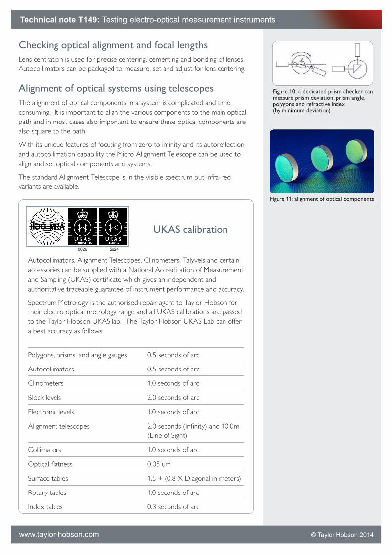
The fixed test wedge (code 137-1940)
This can be used to quickly check the accuracy of any autocollimator. It introduces a fixed angle of deviation nominally of 60 seconds by rotating the wedge from minimum to maximum deviation and comparing this with the readings on the autocollimator (see figure 4).
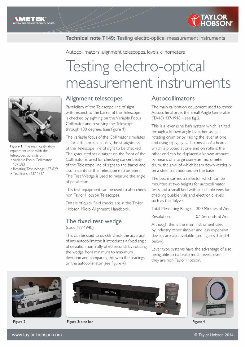
AutocollimatorsThe main calibration equipment used to check Autocollimators is the Small Angle Generator (TA48) 137-1918 – see fig 2.
This is a lever (sine bar) system which is tilted through a known angle by either using a rotating drum or by raising the lever at one end using slip gauges. It consists of a beam which is pivoted at one end on rollers; the other end can be displaced a known amount by means of a large diameter micrometer drum, the anvil of which bears down vertically on a steel ball mounted on the base.
The beam carries a reflector which can be mounted at two heights for autocollimator tests and a small bed with adjustable vees for checking bubble vials and electronic levels such as the Talyvel.
Total Measuring Range: 200 Minutes of Arc
Resolution: 0.1 Seconds of Arc
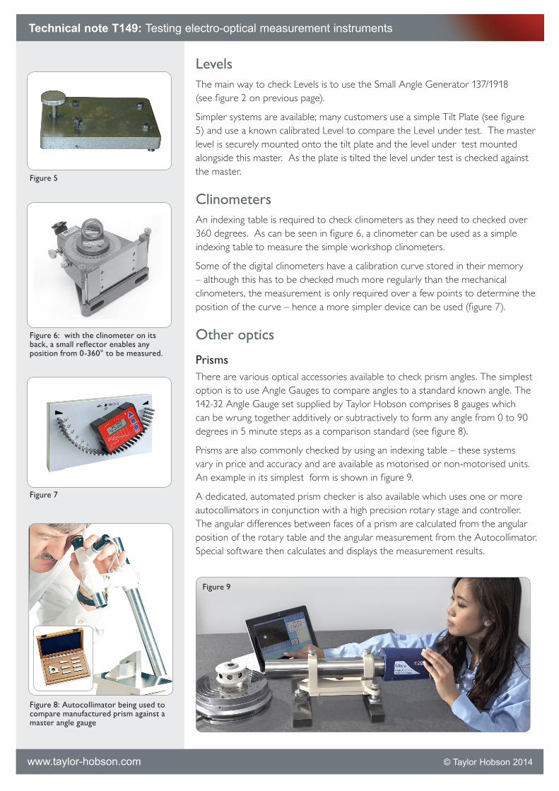
Although this is the main instrument used by industry other simpler and less expensive devices are also available (see figures 3 and 4 below).
Lever type systems have the advantage of also being able to calibrate most Levels, even if they are non Taylor Hobson.
Technical note T149: Testing electro-optical measurement instruments
www.taylor-hobson.com © Taylor Hobson 2014
Figure 3: sine barFigure 2 Figure 4
Autocollimators, alignment telescopes, levels, clinometers
Testing electro-optical measurement instruments
Figure 1: The main calibration equipment used with the telescopes consists of:•Variable Focus Collimator
137-583 •Rotating Test Wedge 137-829• Test Bench 137-1917
LevelsThe main way to check Levels is to use the Small Angle Generator 137/1918 (see figure 2 on previous page).
Simpler systems are available; many customers use a simple Tilt Plate (see figure 5) and use a known calibrated Level to compare the Level under test. The master level is securely mounted onto the tilt plate and the level under test mounted alongside this master. As the plate is tilted the level under test is checked against the master.
ClinometersAn indexing table is required to check clinometers as they need to checked over 360 degrees. As can be seen in figure 6, a clinometer can be used as a simple indexing table to measure the simple workshop clinometers.
Some of the digital clinometers have a calibration curve stored in their memory – although this has to be checked much more regularly than the mechanical clinometers, the measurement is only required over a few points to determine the position of the curve – hence a more simpler device can be used (figure 7).
Other optics
PrismsThere are various optical accessories available to check prism angles. The simplest option is to use Angle Gauges to compare angles to a standard known angle. The 142-32 Angle Gauge set supplied by Taylor Hobson comprises 8 gauges which can be wrung together additively or subtractively to form any angle from 0 to 90 degrees in 5 minute steps as a comparison standard (see figure 8).
Prisms are also commonly checked by using an indexing table – these systems vary in price and accuracy and are available as motorised or non-motorised units. An example in its simplest form is shown in figure 9.
A dedicated, automated prism checker is also available which uses one or more autocollimators in conjunction with a high precision rotary stage and controller. The angular differences between faces of a prism are calculated from the angular position of the rotary table and the angular measurement from the Autocollimator. Special software then calculates and displays the measurement results.
Technical note T149: Testing electro-optical measurement instruments
www.taylor-hobson.com © Taylor Hobson 2014
Figure 5
Figure 6: with the clinometer on its back, a small reflector enables any position from 0-360° to be measured.
Figure 7
Figure 8: Autocollimator being used to compare manufactured prism against a master angle gauge
Figure 9
Checking optical alignment and focal lengthsLens centration is used for precise centering, cementing and bonding of lenses. Autocollimators can be packaged to measure, set and adjust for lens centering.
Alignment of optical systems using telescopesThe alignment of optical components in a system is complicated and time consuming. It is important to align the various components to the main optical path and in most cases also important to ensure these optical components are also square to the path.
With its unique features of focusing from zero to infinity and its autoreflection and autocollimation capability the Micro Alignment Telescope can be used to align and set optical components and systems.
The standard Alignment Telescope is in the visible spectrum but infra-red variants are available.
UKAS calibration
Autocollimators, Alignment Telescopes, Clinometers, Talyvels and certain accessories can be supplied with a National Accreditation of Measurement and Sampling (UKAS) certificate which gives an independent and authoritative traceable guarantee of instrument performance and accuracy.
Spectrum Metrology is the authorised repair agent to Taylor Hobson for their electro optical metrology range and all UKAS calibrations are passed to the Taylor Hobson UKAS lab. The Taylor Hobson UKAS Lab can offer a best accuracy as follows:
Polygons, prisms, and angle gauges 0.5 seconds of arc
Autocollimators 0.5 seconds of arc
Clinometers 1.0 seconds of arc
Block levels 2.0 seconds of arc
Electronic levels 1.0 seconds of arc
Alignment telescopes 2.0 seconds (Infinity) and 10.0m (Line of Sight)
Collimators 1.0 seconds of arc
Optical flatness 0.05 um
Surface tables 1.5 + (0.8 X Diagonal in meters)
Rotary tables 1.0 seconds of arc
Index tables 0.3 seconds of arc
Technical note T149: Testing electro-optical measurement instruments
www.taylor-hobson.com © Taylor Hobson 2014
Figure 10: a dedicated prism checker can measure prism deviation, prism angle, polygons and refractive index (by minimum deviation)
Figure 11: alignment of optical components
0026 2624

Micro-Alignment Telescope
Used for checking and setting for example:
• Alignment:(seriesofboresorbearings)
•Squareness:(columntoabase)
•Parallelism:(seriesofrollers)
• Level/flatness:(machinebedfoundation)
•Straightness:(railsorguideways)
...with its optical and mechanical axes aligned to within 3 seconds, a typical accuracy of 50–70 um at 30 m is achievable.
Autocollimators
Used for measuring for example:
•Angle:(indexingheadaccuracy)
• Straightness:(machinetoolslidesin two axes)
•Squareness:(spindlestoslideways)
•Parallelism:(slideways)
...from inexpensive visual to dual axis digital systems capable of measuring 0.01 second, equivalent to 50 nm per m.
Electronic Levels and Clinometers
Used for angle and level measurements:
•Level/flatness:(granitetables)
• Straightness&twist:(machineslides)
• Squareness:(ofmachinecolumns)
• Angle:(remotemonitoringofmovement of structures)
...from full 360 degree measurement to level measurements to 0.1 second.
© DiskArt™ 1988
Taylor Hobson UK (Global Headquarters)PO Box 36, 2 New Star RoadLeicester, LE4 9JD, England
Tel: +44 116 276 3771 [email protected]
Taylor Hobson FranceTel: +33 130 68 89 30 [email protected]
Taylor Hobson GermanyTel: +49 611 973040 [email protected]
Taylor Hobson IndiaTel: +91 80 67823200 [email protected]
Taylor Hobson ItalyTel: +39 02 946 93401 [email protected]
Taylor Hobson JapanTel: +81 36809 2406 [email protected]
Taylor Hobson KoreaTel: +82 31 888 5255 [email protected]
Taylor Hobson China Beijing OfficeTel: +86 10 8526 2111 [email protected]
Taylor Hobson China Shanghai OfficeTel: +86 21 58685111-110 [email protected]
Taylor Hobson SingaporeTel: +65 6484 2388 Ext 120 [email protected]
Taylor Hobson USATel: +1 630 621 3099 [email protected]
Our electro-optical metrology product range comprises:
Windows® based software programs are available for computer processing and graphic output of flatness, straightness, squareness, twist and polygons up to 72 faces.
Calibration of all instruments is traceable to international standards.
This application note demonstrates just one of the applications for the Taylor Hobson electro-optical metrology range.
Contact Spectrum Metrology to discuss your own measurement requirements.
Spectrum Metrology Ltd Unit 8 Ireton Avenue Leicester, LE4 9EU
Tel: (44)(0)116 276 6262, Fax (44)(0)116 276 6868Email: [email protected] www.spectrum-metrology.co.uk
Technical note T149: Testing electro-optical measurement instruments
www.taylor-hobson.com © Taylor Hobson 2014