Testing And Evaluation Of Electrolytic Metal Recovery ...
67
CAI ENGINEERING 34333 VALEWOOD DRIVE OAKTON, VA 22124-2227 703/264-0039 TESTING AND EVALUATION OF ELECTROLYTIC METAL RECOVERY UNITS AT THE NORFOLK NAVAL SHIPYARD NOVEMBER 17, 1993 PREPARED FOR: NAVAL FACILITIES ENGINEERING SERVICE CENTER 560 LABORATORY DRIVE PORT HUENEME, CA 93043-4300 PROJECT MANAGERS: JENNIE KOFF KATHERINE FORD PREPARED BY: GEORGE CUSHNIE MARK EELMAN
Transcript of Testing And Evaluation Of Electrolytic Metal Recovery ...

CAI ENGINEERING 34333 VALEWOOD DRIVE OAKTON, VA 221 24-2227
703/264-0039
TESTING AND EVALUATION OF ELECTROLYTIC METAL RECOVERY UNITS
AT THE NORFOLK NAVAL SHIPYARD NOVEMBER 17, 1993
PREPARED FOR: NAVAL FACILITIES ENGINEERING SERVICE CENTER
560 LABORATORY DRIVE PORT HUENEME, CA 93043-4300
PROJECT MANAGERS: JENNIE KOFF
KATHERINE FORD
PREPARED BY:
GEORGE CUSHNIE MARK EELMAN

SUMMARY REPORT TESTING AND EVALUATION OF ELECTROLYTIC METAL RECOVERY UNITS
AT THE NORFOLK NAVAL SHIPYARD
1 .O INTRODUCTION
1.1 Purpose of the Study
The Naval Facilities Engineering Service Center (NFESC) has been tasked to develop alternative approaches and technologies for the minimization and cost-effective treatment of wastestreams generated from Navy plating operations that contain heavy metals and cyanide. Under this program NFESC is evaluating the electrolytic recovery technology (also termed electrowinning). This technology has been used by private industry for more than 20 years to recover metals and destroy cyanide. However, due primarily to differences in production characteristics between private industry and Navy plating shops, the application of this technology to Navy plating operations has not been widely achieved. The purpose of this project was to implement the technology in a manner that best serves the environmental goals of the Norfolk Naval Shipyard (NNSY) plating shop, to monitor the technology and evaluate its effectiveness in meeting these goals, to determine the suitability and reliability of the technology at this site, and to develop operation and maintenance procedures for permanent operation of the units.
1.2 Background Information
1.2.1
The NNSY plating shop operates various metal finishing processes to support the fleet maintenance activities of the Shipyard. Production levels at the shop vary significantly and are heavily dependent on the overall workload at the Shipyard (Le., current number and sue of ships present at the NNSY for maintenance). The most frequently used electroplating processes include: hard chrome, nickel, copper and silver plating. This project focused on the silver and copper cyanide plating processes. Bath chemistry and tank size data for these two processes are presented in Appendix A.
The copper plating solution is operated in the range of 6 to 9 oz/gal CuCN. This bath is used more frequently as a copper strike under nickel or silver plating than for copper build-up. After plating, the parts are rinsed in a drag-out recovery tank followed by a two stage counterflow rinse (the counterflow rinse is operated as a still or non-flowing rinse). The rinse water in the drag-out tank is used for evaporative make-up in the plating tank.
Norfolk Naval Shipyard Platlng Shop
The silver bath is operated at 3.0 to 5.5 troy oz per gallon silver and 5.5 to 7.5 oz (Avoir) free cyanide. Parts exiting the silver plating tank are rinsed in a still rinse followed by a hot rinse.
Rinse waters in the still rinses are discharged from their tanks on a batch basis rather than a continuous overflow. This practice is followed primarily to reduce the volume of wastewater generated. Wastewater volume is particularly a problem at NNSY with cyanide bearing waters. The industrial wastewater treatment plant (IWTP) is unable to effectively treat the cyanide wastewaters and the wastewaters are therefore collected, stored and hauled off-site in rail cars. In addition to rinse waters, other wastewater generated by the shop includes washdown water and spent process solutions (typically alkaline cleaners and acid dips). The various wastewaters are discharged to the basement of the plating shop where they are segregated (cyanide, chromium and acid/alkaline) by curbing. The wastewaters are pumped to segregated underground tanks located outside the plating shop and then transferred by pumping to the IWTP.
The IWTP system includes conventional cyanide destruction processes that have not been in use since approximately 1991. These systems (one old unit and two new units) operate on a batch basis. Sodium hypochlorite is used as the treatment reagent. The new systems have been infrequently used due to their mechanical complexity and a lack of an operating manual. The old system is functional, but has not been in use for approximately two years. At that time, the treatment of a single batch of
1
cyanide wastewater took one to two weeks to conduct (normal treatment times at other locations are 3 hrs. or less). At present, the IWTP is unable to approach this limitation. As a result, during 1992, a volume of 43,800 gal of cyanide wastewater was hauled off-site for treatment at a cost of $2.90 per gallon.
1.2.2 Electrowinning'
Electrowinning is one of the two most widely used methods of metal recovery in the plating industry, the other being atmospheric evaporation. Electrowinning is most frequently used to: (1) reduce the mass of inexpensive regulated metals (e.g., zinc, copper, lead) and cyanide being discharged to treatment and thereby reduce the quantity of treatment reagents used and the quantity of sludge generated and/or (2) recover expensive common metals (e.g., nickel and cadmium) or precious metals (e.g., silver and gold) for recoveryhecycle and thereby reduce overall operating costs. In either case, electrowinning is most often applied for gross metal recovery from concentrated solutions such as spent baths, drag-out rinses, ion exchange regenerant or reverse osmosis reject. Electrowinning is applied to a wide variety of chemical solutions in the electroplating industry. The metals most commonly recovered by electrolytic treatment are copper, cadmium, zinc and precious metals.
The basic unit of the electrowinning technology is the electrolytic cell: two electrodes (anode and cathode) are placed in a solution containing ions, where there occurs a movement of ions toward the charged electrodes. Dissolved metals in the electrolyte are reduced and deposited on the cathode. The deposited metal is removed by mechanical (e.g. peelingkraping) or chemical (i.e., stripping) means and either reused as anode material or sent off-site for refininglreuse or disposal.
The types of cathodes used in electrowinning can be grouped into three categories. These include, in order of increasing surface area: (1) flat plate, (2) expanded metal or wire meshhcreen, and (3) reticulate carbon and graphite types. The flat plate cathodes are most frequently used for applications of gross metal recovery from concentrated solutions (e.g., >1 g/l of metal). The expanded metal, wire mesh and reticulate cathodes are used over a range of metal concentrations, with the latter group effective in some cases in the low mal range.
Various types of anodes are also used. The material of construction is typically selected based on the chemistry of the electrolyte. Types of anode materials include: stainless steel; titanium; lead alloy; graphite; and platinum or rare earth metal coatings over titanium or other base metals or ceramic materials.
There are several common terms used in describing the equipment and processes relative to electrowinning. The basic electrolytic cell is composed of two electrodes, one anode (positive charge) and one cathode (negative charge). The chemical reactions that take place at the anode are oxidations and the reactions at the cathode are reductions. The solution is referred to as an electrolyte. When a direct current (D.C.) is applied to the cell, the anions present in the electrolyte migrate toward the anode and the cations migrate toward the cathode. An important controlling factor in the process is the amount of current flowing through the cell. The level of current is measured in amperes per unit area of electrode (typically, amperes per square foot) and is referred to as the current density. Current density affects the nature of the electroplated deposit, the distribution of the deposit, the current efficiency, and to some extent whether a deposit forms at all. In electrowinning, the theoretical quantity of metal that is deposited onto the cathode is described by Faraday's Law. This law states that the amount of chemical change produced by an electric current is proportional to the quantity of electricity used. Some of the electric current is used for reactions other than metal deposit. Electroplaters refer to the ratio of desired chemical change (deposit) to the total chemical change as the current efficiency, usually expressed as a percentage of current applied.
As indicated previously, the current density has a substantial impact on the rate of metal deposit. It is desirable to operate electrowinning processes at the maximum current density where good deposition
'Reference: Cushnie, George, Assessment of Pollution P r e v e m d Control Te&x&gy for P m ODer- National Center for Manufacturing Sciences, Ann Arbor, MI, February, 1994 (estimated publication date).
2

still takes place. The current density should, however, not exceed that which deposits metal faster than ions can diffuse through the electrolyte. When the thin film of electrolyte surrounding the cathode is depleted of metal ions, a condition referred to as concentration polarization occurs. This results in an adverse effect on the current efficiency as well as the quality of the deposit, as a result of excessive hydrogen evolution at the cathode and oxygen evolution at the anode. The allowable or critical current density is determined by the concentration of metal ions in the electrolyte and the thickness of the film surrounding the cathode. Innovations in the design of electrowinning devices have generally focused on extending the operating range of the process by: (1) increasing the surface of the cathode (Le., high surface area), or (2) reducing the thickness of the film using agitation or heating.
For most applications, the primary use of electrowinning is the recovery of metal. However, when performed with an electrolyte containing cyanide and the proper anode material, the process also oxidizes some of the cyanide at the anode (alternatively CN can be oxidized with hypochlorite ions which result from the electrochemical oxidation of chloride ion in a basic medium). Although the anodic reactions are given less consideration in most applications, they can play an important role in the economic viability of the process by reducing the treatment reagent requirements for end-of-pipe treatment .
1.3 Scope of Work
The testing at NNSY consisted of the following major tasks: (1) maintaining the operation of two electrowinning units applied to silver and copper plating rinse waters for a period of four weeks; (2) mohitoring the units for operational parameters (e.g., amperage and voltage settings); (3) collecting rinse water samples to evaluate the effectiveness of the units; (4) collecting related facility data to determine the cost effectiveness of the units; (5) evaluating the suitability and maintainability of the units; (6) determining the optimal operating mode and settings for permanent use of the units at NNSY; (7) conducting training for NNSY personnel on the operation and maintenance of the units; and (8) preparing a summary report.
1.4 Summary of Results
Testing of the ERUs and data collection efforts during the project have lead to several conclusions:
1. The ERU technology can be effectively implemented at the NNSY plating shop. Use of the units will require minimal operation and maintenance (O&M) time. O&M can be performed by plating shop personnel. Weekly sampling (the frequency may be reduced in the future, depending on the variability of operating parameters) of the rinse water is necessary to evaluate operating parameters and prepare recommendations for adjustments. The analytical work will be performed by Code 134. Initial operating parameters have been established and are presented in Appendix B.
2. The silver and copper ERUs will serve a useful application at NNSY under the present conditions. They will permit the facility to eliminate the discharge of cyanide bearing rinse waters from these two processes. Because cyanide rinse waters are hauled off-site for treatment, there will be a substantial annual savings. Under present conditions, the payback periods for the units are estimated to be 0.36 years (silver ERU) and 0.56 years (copper ERU).
3. Long term data are needed to determine the effect that an initially low copper concentration in the feed stream will have on the performance of the ERU. The limited testing performed during this project indicated that a copper concentration of greater than 21 mg/l is needed to initiate rapid copper deposition. If long term data continue to show this trend, it may be necessary to adjust the recommended operating procedure for this unit.
3

4. If the recommendations as described in Section 5.1 for correcting the cyanide complex problem are implemented, it will no longer be cost effective to operate the copper ERU. However, this unit may find cost effective application on the cadmium platinghinse. The silver ERU can be cost effectively operated under either conditions. This unit will be especially useful if plating work currently performed at Charleston NSY is moved to NNSY.
2.0 TEST PROCEDURES, CONDITIONS AND RESULTS
2.1 CapperERU
2.1.1
During their ERU program, NFESC purchased ERUs from various manufacturers. Each of the ERUs that were purchased met some basic design criteria, however there are some significant differences between most of the units (e.g., methods of reducing concentration polarization). Also, the units vary in terms of purchase price. One of the objectives of NFESC is to determine if and under what conditions the more expensive design features are necessary.
The ERU used for the copper plating tests was manufactured by ACCA (Attleboro Falls, MA). Manufacturer's literature providing a description of the equipment and specifications is presented in Agpendix C. This ERU is a very basic unit (least expensive of all units purchased) that does not have expensive design features for reducing concentration polarization. The unit consists of an electrolytic cell tank with an integral rectifier (25 A, 12 V) and solution pump (1/15 hp). Solution is pumped into the electrolytic cell tank (24 liters/min) through a distributor at the bottom of the tank and overflows a weir at the top (opposite side of the tank from the distributor). The flowing solution is the only means of circulation and agitation. The unit operates with four anodes and four cathodes. The location of the bus bars in the tank provide for a 2 in" anode to cathode spacing. Spacers present between the anodes and cathodes are constructed of plastic plate with holes drilled through the plate to expose the anodes and cathodes to one another. However, each set of electrodes (i.e., one anode and one cathode) are separated by a solid plastic plate that prevents electrical communication between sets of electrodes. As a resutt, plating is generally restricted to one side of each cathode (some "wrapping" of the deposit occurs). The unit was supplied with platinized titanium mesh anodes (11" x 11"). Two types of cathodes were used during testing: (1) 11.00" x 11.75" flat plate stainless steel and (2) 11 .OO" x 13" copper mesh.
Descrlption of Equipment and Installation
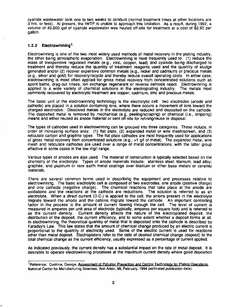
The unit was mounted approximately 20" above the rinse tank surface. Solution was pumped from the first counterflow rinse to the ERU and returned by gravity to the rinse tank (see Exhibit 2-1).
2.1.2 Test Procedures, Conditions and Results
One of the objectives of this project was to operate the ERUs on-line during actual production. However, due to fact that the test period coincided with a low production period at the plating shop, most of the testing of the copper ERU was done off-line (i.e., ERU was connected to a small side tank rather than the rinse tank).
Four test runs were performed during the four week test period. During the first three tests, the ERU was connected to the small off-line test tank rather than the rinse tank. During the fourth test the unit was connected to the rinse tank. Prior to the four week test period, NFESC installed the ERU equipment and conducted off-line testing of the ERU to establish initial operating parameters such as the amperage setting.
The first test run (Cu-1) was performed using flat plate cathodes. A contrived rinse water was prepared by adding 4.0 liters of copper plating bath to 80.2 liters of tap water. The ERU was operated with a current range of 4.6 to 7.0 A for a period of 49.7 hrs. The test was interrupted
4
E
a
w E P
3 3
Cyanide Copper Plating Tank
~
Recovery Rinse
I btum tom ERU 'f"l Rinse Rinse
+ Direction of Work Flow
Exhibit 2-1 a. Copper ERU Installation (plan view)
Silver ERU
Cyanide Silver Plating Tank
Return tom ERU
ERU Rinse
Final Rinse 1 r
Direction of Work Flow
Exhibit 2-1 b. Copper ERU Installation (plan view)
Exhibit 2-1. Drawings Showing the Locations of ERU Installations at NNSY
5
k

when the solution pump lost its prime while unattended during a weekend. During this test, the copper concentration of the contrived rinse water was reduced from 2,680 mg/l to 1,400 mg/l (approximate removal of 102 g Cu). Cyanide was reduced from 3,900 mg/l to 3,200 mg/l during the initial 21.9 hrs of operation (additional cyanide samples were not taken due to the pump failure).
The second test run (Cu-2) was performed using the copper mesh cathodes. A contrived rinse water was prepared by adding 3.0 liters of copper plating bath to 80.2 liters of tap water tap. The ERU was operated with a current range of 2.5 to 4.5 A for a period of 136.5 hrs. Test Cu-2 was also interrupted when the solution pump lost its prime while unattended during a weekend. During this test, the copper concentration of the contrived rinse water was reduced from 1,280 mg/l to less than 1 mg/l (approximate removal of 102 g Cu). Cyanide was reduced from 1,950 mgA to 100 mg/l.
The third test run (Cu-3) was performed using the copper mesh cathodes. A contrived rinse water was prepared by adding 0.7 liters of copper plating bath to 80.2 liters of tap water tap. The ERU was operated with a current range of 2.0 to 3.5 A for a period of 93.8 hrs. During this test, the copper concentration of the contrived rinse water was reduced from 421 mg/l to less than 0.4 mg/l (approximate removal of 34 g Cu). Cyanide was reduced from 550 mg/l to 8 mg/l.
The fourth test run (Cu-4) was performed using the copper mesh cathodes. During this test the ERU was connected to the rinse tank (volume = 389 gal). Because the rinse tank did not contain a substantial concentration of copper (C 1 mg/l), 0.5 liters of copper plating bath were added to it for testing purposes. The ERU was operated with a current range of 2.2 to 2.5 A for a period of 91.5 hrs. During this test, the copper concentration of the rinse water was reduced from 21.4 mg/l to less than 17.1 mg/l (approximate removal of 6.3 g Cu). Cyanide was reduced from 36 mg/l to 25 mg/l.
The field test data for the copper ERU are presented in Appendix D and the analytical results are presented in Exhibit 2-2.
2.1 Silver ERU
2.1.1 Description of Equipment and Installation
The ERU used for the silver plating tests was manufactured by BEWT (Warwickshire, England). Manufacturer's literature providing a description of the equipment and specifications is presented in Appendix E. The unit consists of an electrolytic cell tank with an integral rectifier (25 A, 12 V) and solution pump (1/15 hp, 12 literslmin). The unit operates with three anodes and two cathodes. These electrodes are contained in an "electrolysis chamber" where a fluidized glass bead bed is used for agitation. The spacing between anodes and cathodes is approximately 0.5 in. The unit was supplied with platinized titanium mesh anodes (4.9 x 6.9"). Two types of cathodes were used during testing: (1) 5.0" x 7.0" flat plate stainless steel and (2) 6.0 x 6.5" stainless steel mesh.
The unit was mounted approximately 6 above the surface of the rinse water. Solution was pumped from the still rinse to the ERU and returned by gravity to the rinse tank (see Exhibit 2-1).
2.1.2 Test Procedures, Conditions and Results
One of the objectives of this project was to operate the ERUs on-line during actual production. However, due to fact that the test period coincided with a low production period at the plating shop, some of the testing of the silver ERU was done off-line.
Three test runs were performed during the four week test period. During the first two tests, the ERU was connected to a small test tank rather than the rinse tank. During the third test the unit was connected to the rinse tank.
The first test run (Ag-1) was performed using the flat plate cathodes. A contrived rinse water was prepared by adding 1.2 liters of silver plating bath to 35.7 liters of tap water. The ERU was operated
6

Exhibit 2-2. Analytical Results for the Copper ERU
Total Sample No. Sample No. Dateflime Hrs. Elasped Cu, mg/l CN, mg/l CNO, mg/l Cu-l-MOOl CU-l-COO1 6:10:20 Cu-I-MO02 6:15:15
CU-1 -MOO4 7:15:00 CU-1 -MOO5 8:8:15 Cu-1 -MOO6 8:12:00
CU-1 -MOO3 CU-1 -COO2 7:8:15
12:16:00 13:8:30
13:15:30 14:8:45 14:15:00 15:8:00 15:12:00 18:8:30
* Cu-3-MO01 Cu-3-COO 1811 1110 Cu-3-MO02 18:l l :50 Cu-3-MO03 18:14:50 Cu-3-MO04 19:7:45 Cu-3-MO05 19:15:30 Cu-3-MO06 20:8:30 Cu-3-MO07 C~-3-C002 21 :7:00 Cu-3-MO08 C~-3-C003 22:9:00
Cu-4-MO01 C~-4-C001 22:11:30 Cu-4-MO02 Cu-4-CO02 2511 Or00 Cu-4-MO03 25:lO:OO Cu-4-MO04 Cu-4-CO03 26:7:00
0.0 4.9 21.9 28.7 45.9 49.7
0.0 16.5 23.5 40.8 47.0 64.0 68.0 136.5
0.0 0.7 3.7 20.6 28.3 45.3 67.8 93.8
0.0 70.5 70.5 91.5
2,680 2,760 2,370 2,050 1,480 1,400
1,280 1,020 728 60 1 658 174 109 0.05
42 1 558 403 120 59 0.50 0.50 0.04
21 18 18 17
3,900 45
3,200 3,000
1,950 45
1000
370 1,400 270 1,400 100
550
13 8
36 30
25
Test methods: Total CN-RFA (EPA Method) Free CN-Standard Methods for the Examination of Water and Wastewater (1 985) Cyanates-Standard Methods for the Examination of Water and Wastewater (1 985) Metals-ICP Conductivity-Solu-Bridge pH-Meter
1
7

with a current range of 1.0 to 2.0 A for a period of 142.6 hrs. During this test, the silver concentration of the contrived rinse water was reduced from 856 mg/l to <0.3 mg/l (approximate removal of 31 g Ag). Cyanide was reduced from 1,460 mg/l to 7 mg/l.
The second test run (Ag-2) was performed using the titanium mesh cathodes. A contrived rinse water was prepared by adding 0.6 liters of silver plating bath to 35.7 liters of tap water. The ERU was operated with a current of 2.5 A for a period of 64 hrs. During this test, the silver concentration of the contrived rinse water was reduced from 405 mg/l to <0.08 mg/l (approximate removal of 14 g Ag). Cyanide was reduced from 690 mg/l to 3.2 mg/l.
The third test run (Ag-3) was performed using the titanium mesh cathodes. During this test the ERU was connected to the rinse tank (volume = 220 gal). The ERU was operated with a current of 0.5 A to 2.5 A for a period of 259 hrs. During this test, the silver concentration of the rinse water was steadily reduced from 98.5 mg/l to 3.24 mg/l. The cyanide concentration was reduced from 74 mg/l to 4 mg/l. Only a small volume of production was performed during the test period and therefore the contribution of drag-in was minimal (estimated to be less than 0.5 liters of silver plating bath).
The field test data for the silver ERU are presented in Appendix D and the analytical results are presented in Exhibit 2-3.
3.0 Test Data Evaluation
3.1 Copper Tests
Exhibits 3-1 and 3-2 graphically show the raw test data that was presented previously (Exhibit 2-2). These data indicate that the copper ERU is particularly effective in recovering copper from concentrated solutions (> 1911) and, if given sufficient time, is capable of lowering the copper concentration below 1 mg/l. This unit was also effective in destroying cyanide. During Tests 2 and 3, the cyanide concentration was reduced by 95% and 98%, respectively. The cyanide was oxidized to cyanate (CNO), as indicated in the data for Test 2 (see Exhibit 2-2).
Current efficiency values (the quantity of copper removed per amp-hr) are plotted in Exhibit 3-3. These values were calculated using the current and voltage data contained in Appendix D and the raw data in Exhibit 2-2. Exhibit 3-4 shows the same data plotted as a percentage of the theoretical maximum copper removal rate (based on Faraday's Law). Exhibits 3-5 and 3-6 show the average current efficiency for each test. Exhibit 3-7 shows the average cathode deposition rate for each test, expressed in grams of copper removed per square meter of cathode area per hour.
During the four tests, the unit's current efficiency averaged just under 0.5 glamp-hr, compared to the theoretical maximum of 2.37 g/amp-hr for mono-valent copper. Not surprisingly, efficiency was directly related to metal concentration; Test 1 averaged over 0.9 g/amp-hr (37% efficiency) with a starting concentration of 2.68 g/l of copper, whereas Test 3 averaged under 0.2 g/amp-hr (8% efficiency) with a starting concentration of 421 mg/l (See Exhibits 3-3 through 3-6).
Power consumption, shown in Exhibit 3-8, averaged approximately 60 Kw-hr/Kg of copper recovered. As with current efficiency, the power consumption rate was related to the concentration of metal in the test solution. Test 1, which exhibited the highest current efficiency, consumed less than 6 Kw-hr/Kg; whereas, Test 4 consumed over 200 Kw-hr/Kg. Electrical costs (rectifier only) for each test run are shown in Exhibit 3-9. These costs are calculated based on 100% rectifier efficiency and they do not account for the electricity consumed by the 1/15 hp recirculation pump.
The data from Tests 1, 2 and 3 (off-line tests) are relatively consistent. However, the data from Test 4 (the only on-line test) does not show the same good metal removal and cyanide oxidation rates. The Test 4 data presents concern since there was no production during the on-line test and therefore, no apparent introduction of copper and cyanide into the ERU rinse tank. During Test 4, which covered a time period of 91.5 hrs, there were only small removals of copper and cyanide (19O/, and
8

Exhibit 2-3. Analytical Results for the Silver ERU
Total Sample No. Sample No. Daterrime Hrs. Elasped Cu, mg/l Ag, mg/l CN, mg/l CNO, mg/l Ag-1 -MOO1 Ag-1 -COO1 6:8:40 1,460 400 Ag-1 -MOO2 6:15:00
Ag-1 -MOO4 7:15:00 Ag-1 -MOO5 8:8:15 Ag-1 -MOO6 8:12:00
Ag-1 -MOO3 Ag-1 -COO2 7:8:15
Ag-1 -MOO7 Ag-1 -COO3 121711 5
Ag-2-MO01 Ag-2-CO01 12:16:00 Ag-2-MO02 13:8:30 Ag-2-MO03 13:15:30
Ag-2-MO05 14:15:00 Ag-2-MO04 Ag-2-CO02 14:8:45
Ag-2-MO06 Ag-24003 15:8:00
.Ag-3-M001 Ag-3-CO01 Ag-3-MO02 Ag-3-MO03 Ag-3-CO02 Ag-3-MO04 Ag-3-MO05 Ag-3-MO06 Ag-3-MO07 Ag-3-MO08 Ag-3-CO04 Ag-3-MO09 Ag-3-CO05 Ag-3-MOlO Ag-3-CO06 Ag3-MO11 Ag-3-CO07 Ag-3-MO12 Ag-3-CO08
15:8:30 15:12:00 18:8:30 18:14:50 19:8:45 19:15:30 20:8:30 21 :7:00 21 :15:30 22 :9 :00 25:lO:OO 26:7:00
Test methods: Total CN-RFA (EPA Method)
0.0 6.3 23.6 30.3 47.6 51.3 143.9
0.0 16.5 23.5 40.8 47.0 64.0
0.0 3.5 68.5 78.3 96.3 103.0 120.0 142.5 151.0 168.5 241.5 259.0
34.2 34.2 34.2 34.4 34.4 35.7 0.2
16.2 7.8 1.64 0.02 0.12 0.04
5.85 5.71 5.63 5.60 4.47 4.18 3.36 2.33 2.35 2.00 1.60 2.22
856 238 2.23 1.7 1.6
c0.3 c0.3
40 5 0.9 0.60 0.47 2.41 0.08
98.5 93.0 18.9 18.5 15.3 14.1 10.9 7.00 6.41 4.48 2.87 3.24
840 2,100
7 1,900
690 96
3.3
3.2
74
31
12 11 8 4 4
980
9
51 0
Free CN-Standard Methods for the Examination of Water and Wastewater (1 985) Cyanates-Standard Methods for the Examination of Water and Wastewater (1 985) Metals- IC P Conductivity-Solu-Bridge pH-Meter
9

Exhibit 3-1 Cu Removal, CuCN Tests
3000 T
X- Test 1
X- Test 2
---&--- Test 3
--O--- Test 4 Y .
W ' X-. 0 20 40 60 80 100 120 140
Hours
Exhibit 3-2 Cyanide Destruction, CuCN Tests
100
4 80
8 60
40
B 0 -
I! 20 8 0 0 20 40 60 80 100 120 140
Hours
-X- Test 1, starting CN concentration: 3900 mg/l
-X- Test 2, starting CN concentration: 1950 mgll - Test 3, starting CN concentration: 550 mg/l
Test 4, starting CN concentration: 36 mgA
10

3000 3 s2 2500 5 2000 c P 1500 z
Exhibit 3-3 Current Efficiency, Cu Recovery from CuCN Solution
X
1000
8 500 A X
I
0 0.2 0.4 0.6 0.8 1
CU Removal Rate, glamphr
Exhibit 3-4 Current Efficiency, Cu Recovery from CuCN Solution
s 3000 - c - 2500 - P 2000 c s 1500 CI
A X
4
0 10 20 30 40 50 60
Fbrcantago of Thoomtiul Mutlmum
X Test 1, average current density: 1.391 ampslsq ft of cathode (flat plate)
X Test 2, average current density: 0.686 ampdsq ft of cathode (screen mesh)
A Test 3, average current density: 0.774 ampslsq ft of cathode (screen mesh)
0 Test 4, average current density: 0.573 ampslsq ft of cathode (screen mesh)
X Test 1, average current density: 1.391 amps/sq tt of cathode (fiat plate)
X Test 2, average current density: 0.686 ampslsq ft of cathode (screen mesh)
A Test 3, average current density: 0.774 ampslsq ft of cathode (screen mesh)
0 Test 4, average current density: 0.573 amps/sq tt of cathode (screen mesh)
11
c

i
Exhibit 3-5 Average Current Efficiency, CuCN Tests
1 T 0.9 4 1-1 0.8
E 0.5
0.1
Test 1, average current density: 1.391 amps/sq ft of cathode (fiat plate)
0 Test 2, average current density: 0.686 amps/sq ft of cathode (screen mesh)
Test 3, average current density: 0.774 amps/sq ft of cathode (screen mesh)
Test 4, average current density: 0.573 amps/sq ft of cathode (screen mesh)
Average of 4 tests
Exhibit 34 Average Current Efficiency, CuCN Tests
Test 1, average current density: 1.391 amps/sq ft of cathode (fiat plate)
0 Test 2, average current density: 0.686 amps/sq ft of cathode (screen mesh)
Test 3, average cunent density: 0.774 amps/sq ft of cathode (screen mesh)
8 Test 4, average current density: 0.573 amps/sq ft of cathode (screen mesh)
Average of 4 tests
1 2

Exhibit 3-7 Average Cathode Deposition Rate, CuCN tests
6 t / /
Test 1, average current density: 1.391 amps/sq ft of cathode (flat plate)
[3 Test 2, average current density: 0.686 amps/sq ft of cathode (screen mesh)
Test 3, average cunent density: 0.774 amps/sq ft of cathode (screen mesh)
6 Test 4, average current density: 0.573 amps/sq ft of cathode (screen mesh)
Average of 4 tests
13

250
200
f 150
Y 5 100
50 *
0 ’
Exhibit 34 Average Power Consumption, CuCN Tests
I 4
No adjustment for rectifier efficiency
Exhibit 3-9 Cost of Electricity, CuCN Tests
0.016 -
0.01 4
0.01 2 A 3 g 0.01
p 0.008 B 0 = 0.006
0.004
0.002
0
Test 1, average current density: 1.391 amps/sq ft of cathode (flat plate)
Test 2, average current density: 0.686 amps/sq tt of cathode (screen mesh)
Test 3, average current density: 0.774 amps/sq ft of cathode (screen mesh)
Test 4, average current density: 0.573 amps/sq ft of cathode (screen mesh)
Average of 4 tests
! i
(13 Test 1, average current density: 1.391 amps/sq ft of cathode (flat plate)
0 Test 2, average current densrty: 0.686 amps/sq ft of cathode (screen mesh)
w Test 3, average current density: 0.774 amps/sq ft of cathode (screen mesh)
Test 4. average current density: 0.573 amps/sq f l of cathode (screen mesh)
H Average of 4 tests
(No adjustment for rectifier efficiency)
14

31%, respectively). Of further concern is the fact that the Test 4 conditions more closely represent the unit's future operating environment at NNSY than do those of Tests 1, 2 and 3.
One key difference between Test 4 and the other tests is that Test 4 was initiated with lower copper and cyanide concentrations. It is possible that the cathodes went passive at the end of Test 3 because of the low copper concentration attained during that test and, as a result, there was an insufficient copper concentration at the start of Test 4 to activate the copper deposition process.
3.2 Silver Tests
Exhibit 2-3 presents the raw test data for the silver ERU. In each of the first two tests (off-line tests), the silver concentration was reduced below 1 mg/l. During the third test (on-line) the silver concentration was reduced and maintained below 5 mal (a small volume of production was processed during Test 3). In all three tests the cyanide was oxidized to cyanate to below 10 mg/l. Exhibit 3-10 graphically shows the cyanide destruction results.
These test results indicate that the silver ERU is highly effective for both silver recovery and cyanide oxidation. It is anticipated that this unit will be able to maintain the silver and cyanide concentrations in the ERU rinse below 5 mg/l and 10 mg/l respectively during light to moderate production periods.
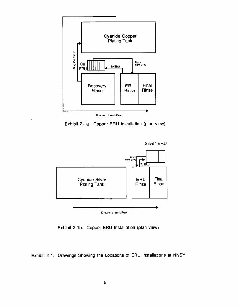
Current efficiency values (the quantity of silver removed per amp-hr) are plotted in Exhibit 3-11. These values were calculated using the current and voltage data contained in Appendix D and the raw data in Exhibit 2-3. Exhibit 3-12 shows the same data plotted as a percentage of the theoretical maximum silver removal rate (based on Faraday's Law). Exhibits 3-13 and 3-14 show the average current efficiency for each test. Exhibit 3-15 shows the average cathode deposition rate for each test, expressed in grams of silver removed per square meter of cathode area per hour.
During the three tests, the unit's current efficiency averaged just under 0.2 g/amp-hr, compared to the theoretical maximum of 4.03 g/amp-hr for mono-valent silver. Efficiency was directly related to metal concentration; Test 1 averaged 0.180 g/amp-hr (4.5% efficiency) with a starting concentration of 856 mg/l of silver, whereas Test 3 averaged 0.298 g/amp-hr (7.4% efficiency) with a starting concentration of 98.5 mg/l (See Exhibits 3-13 and 3-14). Not shown is the fact that during the first six hours of Test 1, when the silver concentration was the highest for all 3 tests, current efficiency approached 60% of the theoretical maximum plating rate. This suggests that at higher concentrations much higher current efficiencies can be achieved with this ERU.
Power consumption per unit mass (see Exhibit 3-16) did not demonstrate a strong inverse relationship with metal concentration as was the case with the copper tests. These results are probably due to the limited range of the test concentrations with the silver ERU. It was notable that Test 2 consumed three times the power per unit mass than the other two tests running at approximately twice the cathode current density as the other two. This suggests that operating at higher current density will translate into a cost penalty. Test 3, run at the lowest current density, but also operating at the lowest concentration, was the most efficient of the three tests.
During Test 3, run with 852.5 liters of fluid (more than 20 times the amount of Tests 1 and 2), the ERU was able to perform with relative efficiency both in terms of silver removal and power consumption, though it was not able to reduce concentrations below 2.87 mg/l in the 259 hours that elapsed. Costs for electricity (Exhibit 3-17) during Test 3 were less then $O.OOl/g; quite small when considering silver's value at over $0.15/g. These costs do not include an adjustment for rectifier efficiency or the cost of running the pump.
15

Exhibit 3-1 0 Cyanide Destruction, AgCN Tests
X- Test 2, starting CN l - concentration: 690 mgll
100 90
8 80 70
6 60
:: g 30 g 20
10 0 0 50 100 150 200 250 0 50 100 150 200 250
I I
300
Hours
16

875 T
775 4 675
1 I
g 575 E 475 E 375
-
E 275 175
a 75 -25
875 ;
Exhibit 3-1 1 Current Efficiency, Ag Recovery from AgCN Solution
i
0 0.25 0.5 0.75 1 1.25 1.5 1.75 2 2.25 2.5
glamphr
Exhibit 3-12 Current Efficiency, Ag Recovery from AgCN Solution
775 675
5 575 5 475 8 375
3 75
c
275 175
-25 0 10 20 30 40 50
Platlng Rate as Percentage of Thoomtlcal Maxlmum
-X- Test 1, average current density: 1.281 amps/sq fl of cathode (fiat plate)
--X- Test 2, averge current density: 2.31 5 amps/sq fl of cathode (mesh) - Test 3, average current density: 0.950 amps/sq fl of cathode (mesh)
--X- Test 1, average current 1 density: 1.281 amps/sqtt of ~
~
cathode (flat plate) I
-X- Test 2, average current I I density: 2.31 5 amps/sq ft of cathode (mesh)
I Test 3, average current I
density: 0.950 amps/sq ft of cathode (mesh)
I
17
1
Exhibit 3-13 Average Current Efficiency, AgCN Tests
0.25 + I
2 0.2 i
a Test 1 : average current density: 1.281 ampdsq ft of cathode (flat plate)
Test 2, average current density: 2.31 5 amps/ sq ft of cathode (mesh)
Test 3, average current density: 0.950 ampslsq ft of cathode (mesh)
E Average of 3 tests
Exhibit 3-14 Average Current Efficiency, AgCN Tests
Test 1, average current density: 1.281 amps/sq ft of cathode (flat plate)
0 Test 2, average current density: 2.315 amps/sq f l of cathode (mesh)
Test 3, average current density: 0.950 amps/sq ft of cathode (mesh)
E Average of 3 tests
18

3.5
3
0.5
0
Exhibit 3-1 5 Average Cathode Deposition Rate, AgCN Tests
Test 1, average current density: 1.281 amps/sq ft of cathode (flat plate)
0 Test 2, average current density: 2.31 5 ampskq ft of cathode (mesh)
Test 3, average current density: 0.950 amps/sq ft of cathode (mesh)
Average of 3 tests
19

45
40 t 3 5 ~
L 0 3 0 t
P ::i = I $ 15 Y
10
0
0.003
0.0025
0.002
0.0015
0.001
P B
0.0005
0
Exhibit 3-16 Average Power Consumption AgCN Tests
Exhibit 3-17 Cost of Electricity, AgCN Tests
I
Test 1, average current density: 1.281 amps/sq ft of cathode (fiat sheet)
0 Test 2, average current density: 2.31 5 amps/sq f t of cathode (mesh)
Test 3, average current density: 0.950
Average of 3 tests
ampslsq ft of cathode (mesh)
Test 1, average current density: 1.281 amps/sq ft of cathode (flat plate)
0 Test 2, average current density: 2.315 amps/sq ft of cathode (mesh)
Test 3, average current density: 0.950 amps/sq ft of cathode (mesh)
Average of 3 tests
No Adjustment for Rectifier Efficiency
20

4.0 ERU SUITABILITY, COST/BENEFIT, RELIABILITY AND MAINTENANCE CONSIDERATIONS
4.1 Copper ERU
4.1.1 ERU Suitability
Due to the low production rate at the NNSY plating shop and the use of a drag-out recovery rinse proceeding the ERU recovery rinse, the quantity of copper metal and cyanide that can potentially be removed by the unit is small. Although there are no actual drag-out data available with which to work, the future operating conditions can be approximated and evaluated using some assumed values. Due to the low production rate, the drag-out volume appears to be less than 500 ml/day (= 0.132 gal). The copper plating bath when operated at 120°F will evaporate approximately 21 gal/day of water. If the recovery rinse is used to make-up for evaporative losses (see tank configuration in Exhibit 2-l) , essentially 100% of the drag-out removed in the recovery rinse will be returned to the plating bath. Assuming 1% of the original drag-out or 5 ml/day of copper plating solution enters the ERU rinse, the mass of copper added per day is only 0.2 grams (based on a bath concentration of 43.55 g/l Cu). Without recovery, the copper concentration would build-up to approximately 7 mg/l in one month (based on a rinse tank volume of 833 liters). Similarly, the cyanide concentration would build-up to approximately 10 mg/l during the same time period. This assumes that none of the rinse water in the ERU rinse tank is sewered.
Lopger term on-line data are needed to determine the effect that a low copper concentration will have on the ERU's performance. The results from Test 4 (the only on-line testing performed during this project) indicate that the unit may require a moderate copper concentration to initiate the deposition of copper. During this test, the unit was ineffective at a starting concentration of 21 mg/l Cu. If long term data continue to show this trend, it may be necessary to shut down the copper ERU until a sufficient copper concentration is attained. It is estimated that a concentration in the range of 50 mg/l Cu will be adequate.
Testing indicated that the Cu ERU can operate using either flat plate or copper mesh cathodes. The copper mesh cathodes appear to be more suitable for this application. This is due primarily to the convenience of recycling the entire cathode rather than having to scrap or peel off the copper deposit, as is necessary with the flat plate types.
4.1.2 Cost/Benefit
Presently, the plating shop generates approximately 43,000 gpy of cyanide wastewater (see data in Appendix F). This wastewater includes discharges from rinse tanks (four cyanide plating processes) and washdown water (less than 1,000 gpy). The cost of haulinghreatment for cyanide wastewater is $2.90/gal. Based on discussions with plating shop personnel, it was estimated that use of the ERU technology would reduce rinse water discharges by 50% (= 5,250 gpy per cyanide plating process). Therefore, the annual savings from avoiding haulingtreatment is $1 5,225 (based on 260 days/yr). The savings from the recovered copper is minimal. The annual cost parameters include: The annual cost parameters include: electricity (estimate: 1,900 kWh @I $0.07/kWh = $133/yr), labor (26 hr/yr @ $40/hr = $1,04O/yr), and cathodes (4 cathodes per year @I $6 ea.). The capital cost of the unit was $5,000.
Annual Savings ltem SavingS Avoid Treatment $15,225
Annual Costs - Electricity $ 133 Labor $1,040 Cathodes u Total $1,197
Payback Period = Equipment Cost ($)/(Annual Savings - Annual Costs) ($/yr)
21

= $5,000/(15,225 - 1,197) ($/yr)
= 0.36 years
4.1.3 Design Evaluation
The copper ERU is the least expensive of the ERUs being tested by NFESC. Therefore, as one would expect, it is a very basic unit that lacks some of the design features of more expensive units. For example, it is not equipped with valves to control the flow of water into the unit. Also, it does not have provisions for air agitation. The hydraulic circulation of this unit is poor. Rinse water enters the electrowinning chamber through a distributor at the bottom of the unit and exits the unit via a weir. Circulation is impeded by the presence of plastic spacers that separate the electrodes.
The copper ERU is more applicable to concentrated metal bearing solutions than to dilute solutions. The poor circulation within the unit and the wide anode to cathode spacing (2 in.) make it less applicable to the dilute solutions.
Due to the design of the unit, it is necessary to add a priming pot (with approximate volume of 1 gal) in the suction line in order to prime the pump. This is due to the presence of a check valve just after the discharge of the pump which prevents priming when the tank reservoir is filled. The priming pot must be located above the pump in-take.
4.1.4 Reliability/Maintainability
Generally, the copper unit proved to be reliable and did not require significant amounts of maintenance during testing. Some problems were encountered with maintaining a solution pump prime, however, these problems are believed to be related to the temporary setup that was used during off-line testing. No pumping problems were encountered when the unit was put on-line with permanent piping.
Weekly samples of the ERU rinse should be taken and sent to Code 134 for pH and copper analyses. Code 134 will subsequently recommend changes to the operating parameters (e.g., amperage) or adjustment of the ERU rinse (e.g., addition of chemicals to increase the pHkonductivity). Other start-up, operation (including recommended operating settings), monitoring and cathode cleaning requirements are covered in the instructions prepared for the NNSY (see Appendix B).
Routine maintenance activities for this unit are minimal. It is anticipated that one to two times per year the unit will require a clean-out to remove debris from the bottom of its tank. The frequency of cleaning will depend mostly on the concentration of impurities such as airborne dirt that accumulate in the ERU rinse. To prevent a build-up of suspended solids, the ERU rinse should be continuously filtered using an in-tank cartridge filter unit. Also, it was noticed that a scum tends to collect at the surface of the ERU tank, due most likely to its limited circulation. The scum can be removed by directing the spray from a hose onto the surface of the ERU tank and pushing the scum over the weir. Again, the presence of the scum will be minimized by using a cartridge fittration unit.
The copper mesh cathodes will last an indefinite time period at NNSY due to the low mass of copper that will be recovered. These cathodes are capable of depositing 5 Ibs or more of copper each (solid sheet approximately 1/8" thick). When they are replaced, the used cathodes can be recycled via the Shipyard's metals recycling program.
22

4.2 Silver ERU
4.2.1 ERU Suitability
It appears that the economic and environmental value of the silver ERU will be significantly greater than that of the copper ERU. This is primarily due to the absence of a drag-out recovery rinse with silver plating. Drag-out recovery is not practical with this process since the plating bath is operated at ambient temperature. As a result, the silver ERU rinse will receive the equivalent of approximately 100 times more plating bath volume than the copper ERU rinse, assuming similar production levels. Assuming a drag-out rate of 500 ml per day, the quantity of silver entering the ERU rinse will be 17 grams/day. Diluted in the ERU rinse, this quantity of silver will result in a concentration of approximately 20 mg/l. Data from the off-line tests indicate that the ERU will be able to recover this quantity of silver overnight, resulting in a concentration of < 1 mg/l by the following morning. Cyanide is destroyed at a slower rate than the recovery rate of silver. However, it appears that the cyanide level will be reduced to below 5 mg/l by the start of each day.
It should be noted that the silver ERU has substantially more capacity than that needed for maintaining the rinse with a drag-out rate of 500 ml per day. If higher drag-out rates are encountered (e.g., if current Charleston NSY silver plating work is moved to NNSY), the ERU can be operated with a higher current and maintain the ERU rinse below 1 mg/l Ag.
Testing indicated that the silver ERU can operate using either flat plate or mesh cathodes. The flat plate cathodes appear to be more suitable for this application. Silver can be easily removed from the flat plate cathodes and recycled via the NNSY silver recycling program. The mesh cathodes are designed to be hung in the silver plating tank and used as anodes. This will require the purchase or fabrication of a holding device and anode bag.
4.2.2 Cost/Benefit
Presently, the plating shop generates approximately 43,000 gpy of cyanide wastewater (see data in Appendix F). This wastewater includes discharges from rinse tanks (four cyanide plating processes) and washdown water (less than 1,000 gpy). The cost of hauling/treatment for cyanide wastewater is $2.90/gal. Based on discussions with plating shop personnel, it was estimated that use of the ERU technology would reduce rinse water discharges by 50% (= 5,250 gpy per cyanide plating process). Therefore, the annual savings from avoiding haulinwtreatment is $15,225 (based on 260 days/yr). The savings from the recovered copper is minimal. The annual cost parameters include: electricity (estimate: 1,900 kWh @ $0.07/kWh I= $133/yr) and labor (26 hr/yr @ $40/hr = $1,04O/yr). The capital cost of the unit was $7,800.
Annual Savings Jte m Savinas Avoid Treatment $15,225
Annual Costs - Electricity $ 133 Labor $1.040 Total $1,173
Payback Period = Equipment Cost ($)/(Annual Savings - Annual Costs) ($/yr)
= $7,800/(15,?25 - 1,173) ($/yr)
= 0.56 years
23

4.2.3 Design Evaluation
The silver ERU appears to be a well designed unit. It has integral piping and valving that permit adjustment of flows and allow for easy priming of the pump. The fluidized glass bead bed is an effective means of agitation which reduces concentration polarization and permits close anode to cathode spacing. The clear plastic tank is useful for viewing the electrowinning process and checking the glass bead level. The unit is versatile in that various anode and cathode designs and materials can be used.
Two minor design problems were noted. First, it is difficult to correctly insert the electrodes into the unit. Slots or guides for the electrodes are located on the back side of the unit, but not on the front. As a result, the electrodes can be inserted improperly which would change the anode to cathode spacing. Even if the electrodes are properly inserted, if they are even slightly bent, they will not have a consistent spacing from one end of the electrode to the other (caused by having the guides only at one end). Despite careful handling, some slight bending of the electrodes occurred during the test period. Another second design problem is the use of small adhesive pads (approximately 1 in. by 1 in.) to hold the electrode connecting wires to the ERU. These adhesive pads became ineffective within approximately two days of operation and the electrode wires hung loosely from the electrodes. This problem could be eliminated by replacing the adhesive pads with Velcro strips.
4.2.4 Re1 ia bi I i ty/Ma i ntai na bi I it y
The silver ERU proved to be very reliable and did not require significant amounts of maintenance during testing. Once the unit is properly started, adjustments to the rectifier or solution recirculation system are rarely, if ever, necessary. Weekly samples of the ERU rinse should be taken and sent to Code 134 for pH and silver analyses. Code 134 will subsequently recommend changes to the operating parameters (e.g., amperage) or adjustment of the ERU rinse (e.g., addition of chemicals to increase the pHkonductivity). Other start-up, operation (including recommended operating settings), monitoring and cathode cleaning requirements are covered in the instructions prepared for the NNSY (see Appendix B).
Routine maintenance activities for this unit are minimal. It is anticipated that one to two times per year the unit will require a clean-out to remove debris from the bottom of its tank and from the glass bead bed. The frequency of cleaning will depend mostly on the concentration of impurities such as airborne dirt that accumulates in the ERU rinse. To prevent a build-up of suspended solids, the ERU rinse should be continuously filtered using an in-tank cartridge filter unit.
The stainless steel cathodes with require periodic cleaning (Le., silver removal). The frequency of removal is expected to be approximately four times per year (based on an estimated capacity of 500 grams of Ag per cathode). However, if the deposit that is formed is flaky or otherwise not fully adherent to the cathode, the frequency of cathode cleaning will be greater.
Silver recovered using the ERU will be recycled via NNSY's silver recovery program
5.0 ADDITIONAL RECOMMENDATIONS FOR NNSY
5.1 Implement On-Site Cyanide Wastewater Treatment
Based on conversations with I W P personnel and a review of available data, it appears that the cyanide treatment problem is due to cyanide complexing with nickel and possibly iron. Analytical data for the cyanide wastewaters is presented in Appendix F support this theory. These data include two sets of historical analytical results (April 19, 1991 and April 20, 1993) and the results of sampling performed during this project. The data indicate that the cyanide wastewaters are highly contaminated with nickel and to a lessor extent with iron. The source of nickel contamination is most likely a leaky nickel filter unit that is located above the cyanide curbed area of the plating shop
24

I I
basement. The source of iron is most likely corroded I-beams in the basement and fallen ferrous alloy parts, racks, etc. The nickel and iron in the basement complex with the cyanide in the rinse waters once they are commingled. The effect of the complexing is illustrated by the comparison of the total cyanide and cyanide amenable (to chlorination) data for the sample taken on October 29, 1993. The difference between these two values (65 mg/l - 14 mg/l = 51 mg/l) can be used to estimate the concentration of cyanide that cannot be removed by the alkaline chlorination process. The treatment problems encountered by the IWTP are compounded by the environmental regulations under which they operate. Cyanide wastewaters treated in the batch units must meet final discharge standards (average monthly concentration of 0.65 mg/l CNT) before being discharged to another treatment process (i.e., metals precipitation).
The treatment of cyanide wastewater is generally not a difficult task. However, if the cyanide is not amenable to chlorination, the process can take weeks to perform and consume large quantities of treatment reagents. Data in Appendix F indicate that the cyanide wastewater generated at the NNSY is contaminated with nickel and to a lesser extent iron. This contamination prevents complete destruction of the cyanide when the conventional alkaline chlorination process is used for treatment. The major source of nickel appears to be a leaky nickel solution filter. The nickel solution from the filter combines with the cyanide rinse water in the basement of the shop before the wastewater is pumped to the storage tank outside the shop. Iron is most likely contributed in a similar manner. The source of iron in the basement is probably corroded I-beams (observed during the testing) that support tanks and ferrous metal parts, racks, etc. that have fallen though the grating and into the basement.
To prevent the formation of the complexed cyanide wastewater and to implement an on-site trea!ment program, NNSY should consider the following recommendations:
1.
2.
Remove the leaking filter and replace it with an in-tank fitter unit.
Clean the basement area. Using dry clean-up methods, remove all foreign objects and shovel out sludges. Wash down the basement floor. Inspect the floor coating and replace the coating, if necessary.
3. Recoat I-beams
4 . Hard pipe cyanide rinse waters to a holding tank in the basement. Use an automatic level control and pump system to convey the rinse water from the tank in the basement to a larger holding tank outside the plating shop. Do not combine the rinse water with other wastewaters such as floor washdown.
5.
6.
Implement a periodic basement inspection program.
Prepare an operating manual for the new cyanide destruction unit located at the IWTP. Rework the unit, if necessary, to have a functional and safe method of cyanide destruction.
The copper ERU may become unnecessary after the implementation of the recommendation in this subsection. NNSY should consider the use of this unit on cadmium platinghinsing since, like silver plating, the cadmium process is operated at ambient temperature and there is limited application for recovery rinsing.
5.2 Drip Pan for Copper Line
It is recommended that a drip pan be fabricated and installed under the floor grating between the copper plating tank and the drag-out rinse tank. Presently, platers carry wetted parts across this space. The drip pan will prevent the loss of drag-out to the basement.
25

APPENDIX A BATH CHEMISTRY AND TANK SIZE DATA

I
disk 16
PHONCON 8 September 93
Person called: Fred Rubin Plating Chemist, Code 134.13
Norfolk Naval Shipyard
Phone # DSN 961-2733
John Kern, Code 134.13 Head Chemist Corrosion Lab
Person calling: Katherine Ford
RE: PLATING BATH COMPOSITION OF SILVER CYANIDE AND COPPER CYANIDE TANKS
I. Plating Bath Y38 Silver Cyanide
Note: increased because of the carbonate build up. is very stable in silver metal. Conversion calculations to metric in ( ) by Katherine Ford.
This bath is very old and the percentage of cyanide is However, the bath
Tank volume is 628 gallons
Ag 3-5 1/2 troy oz per gallon (24.64 g/ l )
Free Cyanide 5 1/2 - 7 1/2 oz Avoir per gallon for a new Actual Free Cyanide is 12.7 -14 oz Avoir per gallon because
bath
the bath is old.
Potassium Carbonate 17.2 oz Avoir per gallon
Because of the composition of this old bath, the drag out of CN may be very high.
Analytical work by Rubin may be different that in the materials laboratory. cyanide. cyanide.
Rubin does titration on free cyanide not total Total CN is calculated from known amount of Ag and free
1

11. Plating Bath # 9 Copper Cyanide
Tank Volume: 838 gallons
Commercial bath Allied Kelite
CuCN 6-9 oz/gallon (bath preparation amount)
CuCN actual amount is 7.9 oz (avoir) per gallon
Total Potassium Cyanide 10.2-16 oz/gallon
Actual Free Cyanide is 2 1/2 oz (avoir) per gallon
Potassium Hydroxide 2-3 oz/gallon to maintain pH
Brighter 0.1 to 2 % (industrial) Grain Refiner (replacement f o r Rochelle Salt and Proprietary)
Analysis is done on free cyanide and is maintained between 1.8- 2 . 5 ' 0 2 (avoir) per gallon
pH is critical on this bath and potassium hydroxide is added as needed. The pH is maintained between 12.8-13.6.
The only additions to this bath are free cyanide and potassium hydroxide.
3

APPENDIX B NNSY OPERATING INSTRUCTIONS

OPERATIONAL SUMMARY FOR THE ACCA ELECTROCELL COPPER RECOVERY UNIT^
1 .o
1 . 1
1.2
1.3
1.4
1.5
1.6
1.7
Start UD Procedures
Check that the emergency drain line ball valve is closed.
Check that the two switches (pump and rectifier) on the front of the unit are in the off position. Check that the powerstat of the rectifier is turned to 0 %.
Fill the priming tank with rinse water.
Check that the inlet ball valve is open.
Turn on the pump. Make sure that water is circulating through the unit and returning to the still rinse.
Hang anodes and cathodes onto their respective bus bars. From the front of the unit, the first and each alternating bus bar is a cathode (four total). The second bus bar and each alternating one is an anode (four total). Make certain that good electrical contact is achieved Use two small C-clamps to secure each copper mesh cathode to its bus bar.
Turn on the rectifier and adjust the amperage to 2.5 A.
2.0
2.1
2.2
2.3
3.0
3.1
3.2
3.3
Monitorina. lupect i n o and Ma' intena nce
Daily: -Check pump operation by observing flow from discharge line.
Weekly: -Check amperage and adjust to 2.5 A, if necessary. -Provide samples of rinse water to Code 134 for analysis per their instructions -Adjust pH of rinse tank per instructions of Code 134.
Bi-annual: -Implement shutdown procedure (see 3.0) and clean system.
-Scrub the bus bars with ScotchBriteGO to remove any corrosion. -Rinse the bus bars and the ERU tank with several gallons of water from a hose. Don't
-Allow this water to drain into the still rinse. leave the hose unattended!
-Change copper cathodes, if necessary (see 4.0). -Check anodes for corrosion or other damage.
Turn off the rectifier and pump. Close the inlet ball valve.
Remove the anodes and cathodes. Rinse the anodes and cathodes over the still rinse with fresh wa?er from a hose. Inspect the cathode for copper build up (see 4.0 for cathode recycling). Inspect the anode for damage such as burning.
If the system requires maintenance, open the drain valve and empty the unit. Open the strainer and permit the suction line to drain. Pump out the priming tank with a hand pump.
These instructions are a summary only. More complete instructions, specifications, warnings, trouble shooting, etc. can be found in the manufacturer's instruction manual that is filed in Joe Taylor's office.
3.4 Close all valves,
3.5 Return the anodes and cathodes to the ERU.
4.0 Cathode Recvcling
4.1 The copper mesh cathodes can be used for many months, until the holes of the mesh have been completely filled in with copper. When this occurs recycle the copper mesh cathodes via the Shipyard metal recycling program.

I
OPERATIONAL SUMMARY FOR THE PMR SILVER RECOVERY UNIT^
1 .o
1.1
1.2
1.3
1.4
1.5
1.6
1.7
1.8
1.9
1.10
1.11
2.0
2.1
2.2
2.3
Start UD Procedure
Check that the two switches (pump and rectifier) on the front of the unit are in the off (up) position.
Check that all valves are closed.
Fill the Reservoir and Chemelec Cell (glass bead tank) with water from a hose. Don't leave the hose unattended!
Open the Internal System Circuit Valve (see diagram on front of unit to locate valves).
Open the bed level valve one turn.
Switch on the pump. Adjust the glass bead level in the Chemelec Cell using the Bed Level Valve. Adjust the water level in the Reservoir using the Internal System Circuit Valve. The correct glass bead level is indicated on the side of the Chemelec Cell. The Reservoir should be filled to approximately the middle of the filter basket located at the top of the reservoir.
Open the External System Circuit Valve. Readjust the levels of the glass beads using the Bed Level Valve, if necessary.
Place anodes (green insulation) and cathodes (black) into their respective slots. The first slot is an anode slot, the second is a cathode, the third is an anode, etc., (i.e., alternating three anodes and two cathodes)
Connect the electrical leads to the anodes and cathodes (red to anode, black to cathode)
Turn on the power switch for the rectifier and adjust the amperage to 1.5 A.
Check the unit periodically to be certain that the glass bead level is correct.
Monitorina. lmoect ion and Ma intenan=
Daily: -Check operation of pump. -Check glass bead level, adjust if necessary.
Weekly: -Check amperage and adjust to 0.5 A, if necessary. -Provide samples of rinse water to Code 134 for analysis per their instructions. -Adjust pH of rinse tank per instructions of Code 134.
Bi-annual: -Implement shutdown procedure (see 3.0) and clean system (rinse out Reservoir and clean out strainers. -Remove silver plate, if necessary (see 4.0) -Check anodes for corrosion or other damage. -Check the glass bead level and add glass beads, if necessary.
These instructions are a summary only. More complete instructions, specifications, warnings, trouble shooting, etc. can be found in the manufacturer's instruction manual that is filed in Joe Taylor's office.

3.0
3.1
Shutdo wn Procedu re
Switch off the rectifier (leave the pump on).
3.2
3.3
3.4
3.5
3.6
3.7
3.8
4.0
4.1
4.2
Remove the electrical leads from the anodes and cathodes and then remove the anodes and cathodes from the ERU. Rinse the anodes and cathodes over the still rinse with fresh water from a hose. Inspect the cathode for silver build up (see 4.0 for cathode cleaning). Inspect the anode for damage such as burning. Place the anodes and cathodes into storage.
Close the Bed Level Valve.
Switch off the pump.
Remove the filter basket from the Reservoir and clean it using fresh water to remove glass beads.
Close the Internal System Circuit Valve and the External System Circuit Valve.
If the system requires maintenance, open the drain valves (2) and empty the unit.
Close all valves.
Cathode C leaning
The stainless steel flat plate cathodes can be used up to several months before the silver plate is removed. The frequency of use of the ERU will depend on the level of production and the amount of drag-out that enters the still rinse.
When the silver plate is sufficiently thick that it is pulling away from the cathode, it is time to remove it (it will have a thickness of 2 to 5 mils at this point). Remove the plastic edge guards and peel the silver from both sides of the cathode. Recycle the silver sheet via the Shipyard metal recycling program.

APPENDIX C COPPER ERU MANUFACTURER'S LITERATURE

I 1 . 1 . . _ . .- ' . . . . . . . . . ... I .
. . . I I . ' . . ' , . b ','
I ,

~ (, TABLE OF CONTENTS 1
1. INTRODUCTION 1.1 DESCRIPTION 12 SPECIFICATIONS
2.
3.
4.
5.
6.
7.
0.
9.
10.
11.
12.
13.
14.
15.
PRINCIPLES OF OPERATION
INSTALLATION PROCEDURES 3.1 UNPACKAGING AND INSPECTION 3.2 INSTALLATION AND SYSTEM START-UP 3.3 WIRING INSTRUCTIONS 3.4 LIQUID LEVELS 3.5 OVERFLOW 3.6 CIRCUIT INTERRUPTION (MODELS A€-/ AND A€-/ / ONLY)
CARE AND MAINTENANCE 4.1 SERVICE 4.2 CLEANING
TROUBLE SHOOTING
ELEGm%g!4am "IN-LINE APPLICATION 1 **
1
2
2
4
5
6
ELEGm@GE??Lm "IN-LINE APPLICATION 2" 7
ELE6?TRocgLLm pH SENSOR AND METER (OPTIONAL)
E&.EGma%?4Lm pH MONITOR INSTRUCTIONS
ELEGYEEXZLL TM FLOAT SWITCH
13
15
16
Eh!&!c-?=km RECTIFIER 18
LIABILITY & WARRANTY 19
(MODELS AE-l AND A€-II ONLY)

1 .
1 . 1
1 . 2 '
JNTRODUCTION . This manual contains a general description, specification, and instructions for the
installation, operation, and care of the ELECTROCELLm by A C C A
TECHNOLOGIES CORP.
lEsa"4 The ELECTROCELLm by ACCA TECHNOLOGIES CORP. is a closed-looped
electrolytic recovery system that removes nickel, cadmium, copper, tin, zinc, silver,
and gold. This unit will also reduce cyanide levels from cyanide based solutions.
The ELECTROCELLm can process solutions up to 200 gallons from a stationary
tank or multiple dragout tanks, provided that they service the same kind of plating
baths.
SPEClFlCATlONS
Height
Width
Length
Weight
Cell Volume
Rectifier
Inlet
Recirculation
Discharge
. Inlet Connection
Discharge Connection
Em erg e ncy Overflow
Utility Requirements
Construction Materials
pH Control and Monitor
25 inches
24 inches
21 inches
100 pounds
12.5 gallons
25 A, 12V
2 - 3 GPM
8 GPM
Gravity Flow
1 /2" NPT
1" NPT
1" NPT
25 A, 115 V
High Density Polypropylene
(optional) See Parts List
(Q - ., ..-•
.*.,e
t

2 . PRINCIPLES OF OPERATION
I
3 .
The ELECTROCELLm is connected in closed loop with the recovery dragout tank.
This metal-bearing solution is pumped to the unit, circulated, electro-deposited onto
the cathodes and returned to the tank via w. Depending on the type of cathode
employed, the deposited metals are removed by scraping or removing the clips and
replacing with new grids.
MSTALLATION
3 .1 U N PACKAGING AN D INSPFCTION
When uncrating the ELECTROCELLM, be sure that all parts are present. Carefully
check for any damage that may have occurred during shipping and uncrating. If
damage has occurred, notify the carrier or ACCA TECHNOLOGIES CORP.
directly .
3 . 2 J N STAL LAT ION AND SYSTEM STA RT-U P
1 . Connect a 1/2" I.D. hose or pipe to unit input. Connect other end to a check valve or
foot valve.
2 . Connect a 1" I.D. hose or pipe to unit output. Connect other end to the recovery
tank.'
I NOTE: This connection must be located above the tank liquid level. I 3 . Connect emergency overflow via 1" coupling to a floor sump or Pollution Control
Fa'cility.
4 . Check that all switches are in the pEE position.
5 . Plug electrical cord into a 115 V, 25 A outlet.
6 . Pour two (2) gallons of water into top of ELECTROCELLm.
7 . Prime inlet pump through check valve.
8 . Turn on InletKirculation Pump. Make sure system is free of air. If properly
primed, the unit will start to fill.
9 . Turn on Rectifier and set for 20 A.
r

3 . 3 m G INSTRUCTIONS
Unit must be attached to a 115 V, 25 A service. The 25 A service will allow for any
fluctuation in the line and prevent the unit from shutting down should there be a
voltage spike to the unit.
NOTE: Pumps are internally connected to the GFI circuit outlets
to prevent any potential electr ical hazard to plant employees.
3 . 4 UDUlD
The liquid level in the Upper Chamber should remain constant with good circulation.
This liquid will overflow steadily into the overflow ports.
A
3 . 5 OVERFLOW
The ELECTROCELLm has a 1 inch Overflow to allow for any electrical malfunction.
This Overflow routes the solution directly to the Pollution Control Facility without
incident.
3 . 6 CIRCUIT INTERRUPTION (MOCELS AE-I AND AE-II ONLY)
The unit is equipped with a Solenoid Valve on the Inlet Line. The Solenoid Valve is
normally in the closed position and will shut down the Inlet Line i f any interruption of
the Service Line occurs. (i.e. Power failure, disconnection at source, etc.)
4 . CARE AND MAINTENANCE
4 . 1 SERVICE
Once the ELECTROCELLW is installed, all Service is the responsibility of the Buyer.
ACCA TECHNOLOGIES CORP. will be available for any extraordinary maintenance,
service requirements, or replacement parts that may be necessary.

I 4 . 2 CLEANlNG
1
2 . UNIT:
DF GsLps.
The Cathode Grids should be cleaned or replaced at regular intervals to maintain
efficient metal recovery. Proper disposal to a metals recycler is recommended for
environmental and financial reasons.
The unit should be cleaned each time the Cathode Grids are removed or serviced.
This cleaning is not confined to the outside only. The Upper Chamber should be rinsed
down to remove any scum, build-up, or corrosion on the electrical bus bars or
contacts.
3 . pHPRORF- (MODELS AE-I AND AE-II ONLY)
The pH probe should be cleaned regularly to assure correct pH readings. Rinse with
water and recalibrate. It may be necessary to replace probe.

I '
Y u a m f A A W u 0 a! I- u W A W
t- Z 0 E L
f 2 W u 0 E + u W A W
t

1
SPECIFICATIONS: RECTIFIER
SPECIFICATIONS
AC Input
m A v w e
CYde
0-25- 0-12votts
Manual Powem
b

' . . .
I 10. SPECIFICATIONS: FEED PUMP
SPEClFlCAllONS
a 4 m 17 ft
1Q" MPT 1/2" MPT
Ill5 3450
1 1 m v 1
mHz O W m.43 A
TEK: Cmdii Box
Potypmpykne, Ceramic, Won 75m m
10-

1
APPENDIX D FIELD TEST DATA FORMS

0, t * .- c
r-"
.- P b
P a
3 U u
Q, c .- w
0
-
Q,
t m B
I

Q,
m c n
9 N

1 9 (u
iqr r- co r-
B B I-


d, a - 1 0,
A
m
7
c
c v)
I-“ 2 0
I I

ci a - a, 7
A
m c.
.- P e


1
APPENDIX E SILVER ERU MANUFACTURER'S LITERATURE

The Chemvlec ' P H R ' 2 5 u r i i t is d e s i g n e d t o r e c o v e r m e t a l s f r o m d i l u Le s o 111 t i o n s .
It. c o n s i s t s of a r e s e r v o i r t a n k and a n e l e c t r o y s i s chamber , j.riter.coririected by p i p e w u r k atid v a l v e s , a l l i n P V C .
I J i ; . ? r t c u r r e n t is s u p p l i e d t o t h e u n i t by a 25 amp Chemelec power s u p p l y .
T h e u n i t c a n be used 3s a ' B a t c h Sys tem ' o r ' C o n t i n u o u s S y s t e m ' .
Wlien used .-n the ' B a t i . t i Svsten i ' t h e s o l u t i o n c i r c u 1 a t . e ~ be tween Lh? r e s e r v o i r t a n k aiicl t l i e e l e c t r o l y s i s chamber u r i t i l t h e metal i n s o l i ~ t i o n is dowri t o an a c c e p t a b l e amount , a n d t h e n d i s c h s r g e d .
Wtieri use [ \ o i i tlie 'Coiitiiiurilis S y s t e m ' t h e so lu t io11 is p i p e d d i r e c t Troni Ltie c o s t oniers o:iri ~ I - U C ~ S S , t h r o u g h t h e e l e c t r o y s i s chamber , i n t c t h e r e s e r v o i r tarilr ~ i i d b a c k t o t h e cus to rne r s uwn s y s t e m .

The c e l l is c o n s t r u c t e d i n uPVC and c o n s i s t s of a n e l e c t r o l y s i s chamber which houses a f low d i s t r i b u t o r i n i ts b a s e . The chamber is p a r t f i l l e d w i t h m i n u t e g l a s s b e a d s t o form a f l u i d i s e d b e d . T h e b e a d s surrourid t h e e l e c t r o d e s and e n s u r e t h a t a h i g h d e g r e e of t u r b u l e n c e and hence mass t r a n s f e r is o b t a i n e d a t t h e e l e c t r o d e s u r f a c e . T l i e expanded metal c a t h o d e s and a n o d e s a re s u s p e n d e d v e r t i c a l l y i n t h e chamber .
The l i q u o r is pumped t h r o u g h t h e c e l l by a n o t o r i s e d m a g n e t i c pump, and t h e s o l u t i o n l e a v e s t h e c e l l o v e r an o v e r f l o w w e i r and i n t o t h e r e s e r v o i r t a n k .
The t h r e e e l e c t r o d e s a r e made of p l a t i n i s e d t i t a n i u m m e s h and a r e marked w i t h red t a p e .
The t w o c a t h o d e s a r e made O F e i t h e r s t a i n l e s s s t e e l s h e e t o r t i t a n i u m and a re marked w i t h b l a c k t a p e .
The o t h e r two c a t h o d e s a r e t h e s t a n d b y s e t .
EXME
T h i s j.s a moto r i sed m a g r i e t i c a l l y d r i v e n pump, TEF-EHP 50/7 w i t h a t o t a l l y e n c l o s e d , f a n c o o l e d , pe rmanen t c a p a c i t o r m o t o r .
ExuLDEK
Direc t c u r r e n t up t o 2 5 amps is s u p p l i e d t o t h e e l e c t r o d e s by t h i s u n i t . Th ree r e d l e a d s a re c o n n e c t e d t o t h e t h r e e anodes and t h e two b l a c k l e a d s a r e c o n n e c t e d t o t h e t h r e e anodes and t h e two b l a c k l e a d s t o t h e c a t h o d e s , by t h e c o n n e c t o r s on t h e l e a d s , f i t t i n g o n t o t h e e n d s o f t h e e l e c t r o d e s .
The power pack h o u s r s t h e ammeter and t h e v o l t m e t e r and t h e i r c o r r e s p o n d i n g c o n t r o l s w i t c h e s .
8

3 I
( I (
1
2 .
3.
4 .
5 .
6.
7 .
8.
9 .
10.
CH S Y m
P l a c e e l e c t r o d e s i n t o t h e e l e c t r o l y s i s chamber i n a l t e r n a t i v e o r d e r , anode - c a t h o d e - anode - c a t h o d e - anode .
Add g l a s s b e a d s i n t o t h e chamber s o t h a t t h e y are ha l fway up t h e mesh of t h e e l e c t r o d e .
C l o s e a l l t h e v a l v e s .
F i l l t h e r e s e r v o i r t a n k w i t h 10 l i t r e s of s o l u t i o n . ( S o l u t i o n m u s t be f r ee from any p a r t i c l e s which may b l o c k t h e f low d i s t r i b u t o r - f i l t e r f i r s t i f n e c e s s a r y )
Open i n t e r n a l s y s t e m c i r c u i t v a l v e .
S l i g h t l y open t h e bed l e v e l v a l v e .
Connect t h e niairl e l e c t r i c a l l e a d t o power s u p p l y and s w i t c h o n . This w i l l o p e r a t e t h e pump and l i q u o r w i l l f l o w t h r o u g h t h e c e l l .
A d j u s t bed l e v e l v a l v e s o t h a t t h e g l a s s b e a d s j u s t c o v e r t h e t o p of t h e mesh e l e c t r o d e s .
Connec t power pack p l u g i n t o e l e c t r i c a l socket on s i d e of 'PHR' u n i t .
S e t c u r r e n t t o t h e r e q u i r e d l e v e l .

I
I
i/
I I1 I
I I
!
' I
Chemelec I C el I
Reservoir I I M'
Clients own supply of solution ./
I :

I l
C u r r e n t s used depend on t h e f o l l o w i n g f o u r f a c t o r s :
1 . C o n c e n t r a t i o n of m e t a l i n s o l u t i o n .
2 . Chemica l e n v i r o n m e n t . 3 . Rate a t which metal is t o b e r e c o v e r e d .
4 . P u r i t y of metal r e q u i r e d .
The f o l l o w i n g t a b l e g i v e s t h e c u r r e n t s e t t i n g s as a g u i d e l i n e t o t h e c o n d i t i o n s s t a t e d .
max approx M e t a l Concen t r a t iori Amps/sq.m E f f i c i e n c y amps Weights
PPH kg/week
Main ta ined x
S i l v e r 50 - 100 30 (max) 33 3 0 . 6
Cadmium 50 - 100 30 (max) 33 3 0.3
Copper a c i d 500 100 80 10 1.5
,/ - Cyan ide 500 67 70 6 1.5
- P y r o p h o s p a t e 500 67 . 7 0 6 0 . 8
Recovery r a t e s shown r e l a t e t o t h e c o n t i n u a l o p e r a t i o n of t h e u n i t i e . 160 h o u r s per w e e k .
A hard d e p o s i t is recommended f o r a n o d i c s t r i p p i n g when anode b a g s s h o u l d be used . (BEWT can s u p p l y anode b a g s on r e q u e s t ) .
F l a k y d e p o s i t s s h o u l d be s u c h t h a t t h e d e p o s i t d o e s n o t f a l l o f f t h e c a t h o d e w h i l s t t h e Cliemelec c e l l is r u n n i n g , b u t b r u s h e s o f f w i t h r e l a t i v e e a s e u s i i i g a wire b r u s h .
When t o b e r e p l a c e d w i t h a s t a n d b y s e t .
mesh of c a t h o d e s l ias ' b l i n d e d ' w i t h metal t h e c a t h o d e s a r e

/L-
I NFURPW7 I UN ON THE USE UF PLCIT 1 NUM-COCITED T I TfiN I UM CINODES
The p la t i r ium c o a t i n g t t t i c k n e s s of a p p r o x i m a t e l y 1.5 - 2 . 5 m i c r o n s r e q u i r e d f o r proper p l a t i n g b a t h o p e r a t i o n a r e p o r e - f r e e when expanded meta l s u b s t r a t e s are u s e d . I n e l e c t r o l y t e s which d o n o t c h e m i c a l l y a t t a c k e i t h e r p l a t i n u m o r t i t a n i u m a l i f e of s e v e r a l y e a r s car1 be e x p e c t e d o f t h e p l a t i n u m - c o a t e d t i t a n i u m anodes . Lony s e r v i c e l i v e s a r e o b s e r v e d even i n s t r o n g s u l p h u r i c a c i d b a t h s - e .g . c o p p e r and rhodium b a t h s . For example , p l a t inum- c o a t e d t i t a n i u m expanded metal a n o d e s have g i v e n t r o u b l e f r e e s e r v i c e fo r more t h a n t w o y e a r s i n s u l p h u r i c a c i d rtiodium b a t h s ( p H 1). I t is, however , a d v i s a b l e to remove t h e a n o d e s f r o m s u c h s t r o n y a c i d b a t h s w h e r i n o t i n u s e o r to a p p l y a l o w anode v o l t a q e to t r i e m , s i n c e o t h e r w i s e t h e r e is t h e d a n g e r o f p e n e t r a t i o n and t h u s of t h e p l a t i n u m l a y e r p e e l i n g o f f .
C a r e must be t a k e n i n b a t l l s w i t h h i g h h a l i d e c o n t e n t . Thus , t h e break-dowri v o l t a g e of t i t a n i u m i n c h l o r i d e b a t h s is 6 - 1ZV d e p e n d i n q on t h e t y p e o f e l e c t r o l y t e and pH v a l u e . In p a r t i c u l a r , t h e e l e c t r o l y t e must n o t c o n t a i n any f l u o r i d e or f l u o r o b a te i o n s .
In media c o n t a i n i n g c t i l o r i d e i t s h o u l d a l w a y s be n o t e d t h a t t h e l i f e o f p l a t i n u m - c o a t e d t i t a n i u m a n o d e s is r e d u c e d s i n c e t h e n a s c e n t c h l o r i d e g e n e r a t e d a t t h e anode a t t a c k s p l a t i n u m .
p l a t i n u m c o a t e d t i t a r i i u m a n o d e s must n o t be used as c a t h o d e s , s i n c e hydrogen g e n e r a t e d l e a d s t o t h e p l a t i n u m layer p e e l i n g o f f a s a r e s u l t o f t h e f o r m a t i o n o f powdery t i t a n i u m h y d r i d e .
7 0 ENSURE LONG L I F E UF 1IiESE &NODES THESE ELECTRODES MUST CILWAYS HAVE A CUW FINUDE VOLTAGE n P P L I E D . I F 1 T . I S REOUIREU TO CLOSE THE CIIEMELEC U N I T UUWN 7flEfJ 01-L E L E C l R U D E S MUST BE REMUVEU FROM CELL BEFORE CURRENT IS SWITUHED O F F . &FTER REMOVFIL E I T H E R LEAVE IMMERSED I N CLECIN WQTER UR WOSHED THOROUGHLY F\ND D R I E D .
A 1 Mecliariica 1 Hand 1 i r r q
AS THESE &NUDES &RE PRODUCED B Y PLQTING/BCIKING OF THE PRECIUUS METAL O N TU THE T I T F I N I U M SUBSTRATE, EXTREME CCIRE MUST BE TCIKEN IN I I0NL)LING THESE ELECTRODES T O ENSURE NO MECH&NICRL DAMAGE UF THE COFITING CfiN OCCUR.
1 ) f inodes must n o t be e x c e s s i v e l y b e n t .
2 ) Ovoid damage by s c r a p i n g , c u t t i n g , p i e r c i n g e t c .
B ) (JDer a t i o n
ELECTROLYTE
1 ) f i c i d i t y s t i ou ld b e n o t less t h a n pH I, i . e . approx W / W S u l p h u r i c a c i d .
s
10%

1
2 ) Temperature i n range ambient t o 50 degrees C .
3 ) Organics (total) 2 O p p m ( i d e a l l y n o t g r e a t e r than t h i s v a l u e ) . H igher conc. may cause s i g n i f i c a n t increase i n c o a t i n g wear r a t e e.g. 50 g / l organic a c i d can reduce the anode l i f e t i m e by a f u n c t i o n o f 10.
4 ) Cur rent density 1 K F I / M sq.

v from w e So-
l ) Tlie s r iodes a r e p l a t i n i s e d t i t a n i u m mesh and t h e c a t h o d e s a r e s L a i n l e s s s t e e l s h e e t / o r t i t a n i u m mesh*. Each is f i x e d i n a s e a l e d s t a i n l e s s s t e e l frame c o n n e c t e d t o a c o p p e r b u s b a r . T h e m e s h t i t a n i u m c a t h o d e s arid anodes a r e i n a s e a l e d t i t a n i u m f rame c o n n e c t e d t o a coppe r b u s b a r . When p l a c e d w i t h i n t h e c e l l , each b u s b a r s i ts on t h e anode o r ca t l i ode b u s b a r s on t h e u n i t .
2 ) A t s t a r t u p i t is recommended t o i n c r e a s e t h e c o n d u c t i v i t y of t h e e l e c t r o l y t e by a d d i t i o n of c a u s t i c s o d a t o g i v e a ptl of 10 or a b p v e .
3 ) Wlieii s u f f i c i e i i L d e p o s i t of metal has formed on t h e e l e c t r o d e s s o R S t o " b l i n d " t h e m e s h , t h e y a r e t o be r e p l a c e d by tlie s t a n d b y s e t . (The e l e c t r o d e s a r e t o be removed w h e n t h e pump is i n o p e r a t i o n ) . G e n e r a l l y change o v e r of c a t h o d e s weekly is recomnended.
T h e d e p o s i t e d s i l v e r is removed from t h e m e s h c a t h o d e b y a n o d i c s t r i p p i n g w i t h i n t h e p l a t i n g b a t h .
The q u o t e d n j i n the Che%eleu r i n s e f o r s i l v e r is u s u a l i n o r d e r t o n i in in i i se , l o s s e s of t h i s v e r y t o x i c m e t a l t o t h e f o l l o w i n g ruriiiirig r i n s e , and b e c a u s e of i t s h i g h v a l u e .
* S t a i n l e s s s t e e l s h e e t c a t h o d e s can be used when s i l v e r is n o t r e u s e d d i r e c t l y a s a n o d e s . By u s i n g s l i e e t , tlie d e p o s i t e d s i l v e r can b e m e c h a n i c a l l y removed i r i s h e e t form f rom Lhe c a t h o d e s .
s

I
53 a F - *
09
51 0
a
\ =-I2 MI
I
- -- b
E E
!z m
c
m
m 00 I
' a a

u,
I I
'1, I
I
7
I i
I I
I -- QC/ r
I :

APPENDIX F NNSY CYANIDE WASTEWATER DATA

,
3
802
REPORT NUnBER I
91NN03049
CSPR. 19 1991 LABORATORY DIVISION
NORFOLK NAWL SHIPYARD PORTSMOUTH, UFI. 23709-5000
Rewrks:

I REPORTS MAY BE DUPLICATED; . 8 , B U T ONLY I N THEIR ENTIRETY. REPORT NUMBER
9 3 NN04362
APR. 2 0 1993 LABORATORY D I V I S I O N
NORFOLK NAVAL SHIPYARD PORTSMOUTH, U A . 23709-5000
TESTS
I Resu 1 t s I I I I 001 I I I I Specification Lirits
UNITS I K O 0 3 9 8 I I I I I I I I I (Louer) (Upper)
Cyan i de T U P TCLP T u p TCLP TUP TCLP T U P TCLP T u p TCLP TCLP
W N I C by EPA200.7 BARlUn by EPA 200.7 CAOliIUl by EPA200.7 CMUlIlPl €PA 200.7 LEAD by EPA 200.7 HERClJRY, COLD VAPOR SELENIUl EPA 200.7 SILVER by €PA 200.7 N I M E L BY EPA 200.7 T W L l U n EPA 200.7 DlESTIoN DATE
Wl 6 7
%A 0.049 ffi5 0.067 W A 0.73 ffiA (0 .50 t W L ( 0 . 0 2 HGA ( 0 . 5 0 ffiA 0.74 %G/L 38 tEA ( 0 . 5 0
rr[;/L ( 0 . 3 5
4/7/93
** Reviewer (signature) Date: I Released (signature) Date: I Code: 134.12 I Phone 6-3029 I ......................................................................................................................
** The person designated to sign for an action verifies, based on personal observation, certified records, or direct report from wtchstanders, and certifies by his signature that the action has been performed in accordance with the rpec i f ied requirements.
Distribution:

Analytical results for sample collected on October 29, 1993 from the NNSY cyanide sump located outside of Bldg. 195 (plating shop). Sample taken by G. Cushnie. Analysis provided by F. Ruben.
Parameter Silver
Cadmium
Copper
Iron
Nickel
Cyanide (total)
Cyanide (amenable)
Eesuaau 5.33
0.38
12.8
1.57
21.8
65
14