Testing a program is the most common way of checking that ... · PDF fileV& Vplanning process....
74
Transcript of Testing a program is the most common way of checking that ... · PDF fileV& Vplanning process....
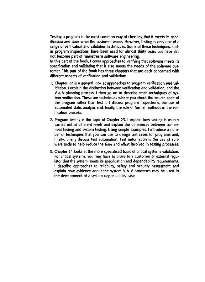
Testing a program is the most common way of checking that it meets its specification and does what the customer wants. However, testing is only one of arange of verification and validation techniques. Some of these techniques, suchas program inspections, have been used for almost thirty years but have stillnot become part of mainstream software engineering.In this part of the book, I cover approaches to verifying that software meets itsspecification and validating that it also meets the needs of the software customer. This part of the book has three chapters that are each concerned withdifferent aspects of verification and validation:
1. Chapter 22 is a general look at approaches to program verification and validation. Iexplain the distinction between verification and validation, and theV & V planning process. I then go on to describe static techniques of system verification. These are techniques where you check the source code ofthe program rather than test it I discuss program inspections, the use ofautomated static analysis and, finally, the role of formal methods in the verification process.
2. Program testing is the topic of Chapter 23. I explain how testing is usuallycarried out at different levels and explain the differences between component testing and system testing. Using simple examples, I introduce a number of techniques that you can use to design test cases for programs and,finally, briefly discuss test automation. Test automation is the use of software tools to help reduce the time and effort involved in testing processes.
3. Chapter 24 looks at the more specialised topic of critical systems validation.For critical systems, you may have to prove to a customer or external regulator that the system meets its specification and dependability requirements.I describe approaches to reliability, safety and security assessment andexplain how evidence about the system V& V processes may be used inthe development of a system dependability case.

22JVerification andvalidation
ObjectivesThe objective of this chapter is to introduce software verification andvalidation with a particular focus on static verification techniques. Whenyou have read this chapter, you will:
• understand the distinctions between software verification andsoftware validation;
• have been introduced to program inspections as a method ofdiscovering defects in programs;
• understand what automated static analysis is and how it is used inverification and validation;
• understand how static verification is used in the Cleanroomdevelopment process.
Contents22.1 Planning verification and validation
22.2 Software inspections
22.3 Automated static analysis
22.4 Verification and formal methods
Verification and validation
During and after the implementation process, the program being developeu must bechecked to ensure that it meets its specification and delivers the functionalityexpected by the people paying for the software. Verification and validation (V &V)is the name given to these checking and analysis processes. Verification and activities take place at each stage of the software process. V & V starts with requirements reviews and continues through design reviews and code inspections toproduct testing.
Verification and validation are not the same thing, although they are often confused. Boehm (Boehm, 1979) succinctly expressed the difference between them:
'Validation: Are we building the right product?'
'Verification: Are we building the product right?'
These definitions tell us that the role of verification involves checking that thesoftware conforms to its specification. You should check that it meets its specifiedfunctional and non-functional requirements. Validation, however, is a more generalprocess. The aim of validation is to ensure that the software system meets the customer s expectations. It goes beyond checking that the system conforms to its specification to showing that the software does what the customer expects it to do. AsI discussed in Part 2, software system specifications do not always reflect the realwishes or needs of users and system owners.
The ultimate goal of the verification and validation process is to establish confidence that the software system is 'fit for purpose'. This means that the systemmust be good enough for its intended use. The level of required confidence dependson the system's purpose, the expectations of the system users and the current marketing environment for the system:
1. Software function The level of confidence required depends on how critical thesoftware is to an organisation. For example, the level of confidence requiredfor software that is used to control a safety-critical system is very much higherthan that required for a prototype software system that has been developed todemonstrate some new ideas.
2. User expectations It is a sad reflection on the software industry that many usershave low expectations of their software and are not surprised when it fails during use. They are willing to accept these system failures when the benefits ofuse outweigh the disadvantages. However, user tolerance of system failures hasbeen decreasing since the 1990s. It is now less acceptable to deliver unreliablesystems, so software companies must devote more effort to verification andvalidation.
3. Marketing environment When a system is marketed, the sellers of the system musttake into account competing programs, the price those customers are willing topay for a system and the required schedule for delivering that system. Where acompany has few competitors, it may decide to release a program before it has

Figure 22.1 Staticand dynamicverification andvalidation
Chapter 22 i<i Verification and validation 517
been fully tested and debugged because they want to be the first into the market. Where customers are not willing to pay high prices for software, they maybe willing to tolerate more software faults. All of these factors must be considered when deciding how much effort should be spent on the V & V process.
Within the V & V process, there are two complementary approaches to system
checking and analysis:
1. Software inspections or peer reviews analyse and check system representations
such as the requirements document, design diagrams and the program source
code. You can use inspections at all stages of the process. Inspections may besupplemented by some automatic analysis of the source text of a system or associated documents. Software inspections and automated analyses are static V &V techniques, as you don't need to run the software on a computer.
2. Sojtv,.are testing involves running an implementation of the software with testdata. You examine the outputs of the software and its operational behaviour tocheck that it is performing as required. Testing is a dynamic technique of verification and validation.
Figure 22.1 shows that software inspections and testing play complementary rolesin the software process. The arrows indicate the stages in the process where the tech
niques may be used. Therefore, you can use software inspections at all stages of thesoftware process. Starting with the requirements, any readable representations of thesoftware can be inspected. As I have discussed, requirements and design reviews arethe main techniques used for error detection in the specification and design.
You can only test a system when a prototype or an executable version of theprogram is available. An advantage of incremental development is that a testableversion of the system is available at a fairly early stage in the development process. Functionality can be tested as it is added to the system so you don't have to
have a complete implementation before testing begins.

518 Chapter 22 ': Verification and validation
Inspection techniques include program inspections, automated source code analysis and formal verification. However, static techniques can only check the correspondence between a program and its specification (verification); they cannotdemonstrate that the software is operationally useful. You also can't use static techniques to check emergent properties of the software such as its performance andreliability.
Although software inspections are now widely used, program testing will alwaysbe the main software verification and validation technique. Testing involves exercising the program using data like the real data processed by the program. You discover program defects or inadequacies by examining the outputs of the programand looking for anomalies. There are two distinct types of testing that may be usedat different stages in the software process:
1. Validation testing is intended to show that the software is what the customerwants-that it meets its requirements. As part of validation testing, you mayuse statistical testing to test the program s performance and reliability, and tocheck how it works under operational conditions. I discuss statistical testingand reliability estimation in Chapter 24.
2. Defect testing is intended to reveal defects in the system rather than to simulate its operational use. The goal of defect testing is to [md inconsistencies betweena program and its specification. I cover defect testing in Chapter 23.
Of course, there is no hard-and-fast boundary between these approaches to testing. During validation testing, you will find defects in the system; during defecttesting, some of the tests will show that the program meets its requirements.
The processes of V & V and debugging are normally interleaved. As you discover faults in the program that you are testing, you have to change the programto correct these faults. However, testing (or, more generally verification and validation) and debugging have different goals:
1. Verification and validation processes are intended to establish the existence ofdefects in a software system.
2. Debugging is a process (Figure 22.2) that locates and corrects these defects.
There is no simple method for program debugging. Skilled debuggers look forpatterns in the test output where the defect is exhibited and use their knowledge ofthe type of defect, the output pattern, the programming language and the programming process to locate the defect. When you are debugging, you can use your knowledge of common programmer errors (such as failing to increment a counter) andmatch these against the observed patterns. You should also look for characteristicprogramming language errors, such as pointer misdirection in C.
Locating the faults in a program is not always a simple process, since the faultmay not be close to the point where the program failed. To locate a program fault,

22.1 Planning verification and validation 519
Figure 22.2 Thedebugging process
Testlresul'~
Locai~.errcrJ
you may have to design additional tests that reproduce the original fault and thatpinpoint its location in the program. You may have to trace the program manually,line by hne, Debugging tools that collect information about the program s execution rna)' also help you locate the source of a problem.
Interactive debugging tools are generally part of a set of language support toolsthat are integrated with a compilation system. They provide a specialised run-timeenvironment for the program that allows access to the compiler symbol table and,from there, to the values of program variables. You can control execution by 'stepping' through Ithe program statement by statement. After each statement has beenexecuted, you can examine the values of variables and so discover the location ofthe fault.
After a defect in the program has been discovered, you have to correct it andrevalidate the system. This may involve re-inspecting the program or regression testing where existing tests are executed again. Regression testing is used to check thatthe changes made to a program have not introduced new faults. Experience has shownthat a high proportion of fault 'repairs are either incomplete or introduce new faultsinto the program.
In principle, you should repeat all tests after every defect repair; in practice, thisis usually too expensive. As part of the test plan, you should identify dependenciesbetween components and the tests associated with each component. That is, thereshould be traceability from the test cases to the components that are tested. If thistraceability is documented, you may then run a subset of the system test cases tocheck the modified component and its dependents.
22.1 Planning verification and validation
Verifica:ion and validation is an expensive process. For some systems, such as realtime systems with complex non-functional constraints, more than half the systemdevelopment budget may be spent on V & V. Careful planning is needed to get themost ou: of inspections and testing and to control the costs of the verification andvalidatie,n process.

520 Chapter 22 * Verification and validation
Acceptancetest plan
Systemintegrationtest plan
Sub-systemintegrationtest plan
Figure 22.3 Testplans as a finkbetween development and testing
You should start planning system validation and verification early in the devel
opment process. The software development process model shown in Figure 22.3 issometimes called the V-model (turn Figure 22.3 on end to see the V). It is an instantiation of the generic waterfall model (see Chapter 4) and shows that test plans should
be derived from the system specification and design. This model also breaks down
system V & V into a number of stages. Each stage is driven by tests that have beendefined to check the conformance of the program with its design and specification.
As part of the V & V planning process, you should decide on the balance between
static and dynamic approaches to verification and validation, draw up standards andprocedures for software inspections and testing, establish checklists to drive pro
gram inspections (see Section 22.3) and define the software test plan.
The relative effort devoted to inspections and testing depends on the type of system being developed and the organisational expertise with program inspection. Asa general rule, the more critical a system, the more effort should be devoted to staticverification techniques.
Test planning is concerned with establishing standards for the testing process,not just with describing product tests. As well as helping managers allocateresources and estimate testing schedules, test plans are intended for software engineers involved in designing and carrying out system tests. They help technical staffget an overall picture of the system tests and place their own work in this context.
A good description of test plans and their relation to more general quality plans isgiven in Frewin and Hatton (Frewin and Hatton, 1986). Humphrey (Humphrey, 1989)and Kit (Kit, 1995) also include discussions on test planning.
The major components of a test plan for a large and complex system are shownin Figure 22.4. As well as setting out the testing schedule and procedures, the test
plan defines the hardware and software resources that are required. This is usefulfor system managers who are responsible for ensuring that these resources are available to the testing team. Test plans should normally include significant amounts ofcontingency so that slippages in design and implementation can be accommodatedand staff redeployed to other activities.

Figure 22.4 Thestructure of asoftware test plan
22.2 Software inspections 521
The hlstlng 1"'Oce5SAdesaiption of the major phases of the testing process. These might be asdescribed earlier in this chapter.
Requirements tracubllityUsers are most interested in the system meeting its requirements and testing shouldbe planned so that all requirements are individually tested.
Tested itemsThe products of the software process that are to be tested should be specified.
Testing scheduleAnovE!rall testing schedule and resource allor.ation for this schedule is, obviously,linked to the more general project development schedule.
Test J'lI!COrdilllg proceduresIt is not enough simply to run tests; the results of the tests must be systematicallyrecorded. It must be possible to audit the testing process to check that it has beencarried out correctly.
Harch,are anICI software requirementsThis sE!ction should set out the software tools required and estimated hardwareutilisation.
Conm'alntsConstr,aints aflfecting the testing process such as staff shortages should be anticipatedin this section.
For snaller systems, a less formal test plan.may be used, but there is still a needfor a formal document to support the planning of the testing process. For some agile
processes such as extreme progranuning, testing is inseparable from development. Likeother planning activities, test planning is also incremental. In XP, the customer is ultimately responsible for deciding how much effort should be devoted to system testing.
Test plans are not a static documents but evolve during the development process. Test plans change because of delays at other stages in the development process. If part of a system is incomplete, the system as a whole cannot be tested. Youthen have to revise the test plan to redeploy the testers to some other activity andbring them back when the software is once again available.
22.2 Software inspections--_._.•.._-_. ----------_.
Software mspection is a static V & V process in which a software system is reviewedto find en·ors. omissions and anomalies. Generally, inspections focus on source code.

Verification and validation
but any readable representation of the software such as its requirements or a designmodel can be inspected. When you inspect a system, you use knowledge of the sys
tem, its application domain and the programming language or design model to dis
cover errors.There are three major advantages of inspection over testing:
1. During testing, errors can mask (hide) other errors. Once one error is discovered,
you can never be sure if other output anomalies are due to a new error or are sideeffects of the original error. Because inspection is a static process, you don't have
to be concerned with interactions between errors. Consequently, a single inspection session can discover many errors in a system.
2. Incomplete versions of a system can be inspected without additional costs. Ifa program is incomplete, then you need to develop specialised test harnesses
to test the parts that are available. This obviously adds to the system develop
ment costs.
3. As well as searching for program defects, an inspection can also consider broader
quality attributes of a program such as compliance with standards, portabilityand maintainability. You can look for inefficiencies, inappropriate algorithmsand poor programming style that could make the system difficult to maintain
and update.
Inspections are an old idea. There have been several studies and experiments
that have demonstrated that inspections are more effective for defect discovery thanprogram testing. Fagan (Fagan, 1986) reported that more than 60% of the errors ina program can be detected using informal program inspections. Mills et al. (Mills,
et aI., 1987) suggest that a more formal approach to inspection based on correctness arguments can detect more than 90% of the errors in a program. This tech
nique is used in the Cleanroom process described in Section 22.4. Selby and Basili(Selby, et aI., 1987) empirically compared the effectiveness of inspections and testing. They found that static code reviewing was more effective and less expensivethan defect testing in discovering program faults. Gilb and Graham (Gilb and Graham,1993) have also found this to be true.
Reviews and testing each have advantages and disadvantages and should be used
together in the verification and validation process. Indeed, Gilb and Graham sug
gest that one of the most effective uses of reviews is to review the test cases for asystem. Reviews can discover problems with these tests and can help design moreeffective ways to test the system. You can start system V & V with inspectionsearly in the development process, but once a system is integrated, you need testingto check its emergent properties and that the system's functionality is what the ownerof the system really wants.
In spite of the success of inspections, it has proven to be difficult to introduce
formal inspections into many software development organisations. Software engineers with experience of program testing are sometimes reluctant to accept thaI

22.2 < Software inspections 523
inspections can be more effective for defect detection than testing. Managers maybe suspicious because inspections require additional costs during design and devel
opment. They may not wish to take the risk that there will be no corresponding sav
ings during program testing.There is no doubt that inspections 'front··load' software V & V costs and result
in cost savings only after the development teams become experienced in their use.
Furthennore, there are the practical problems of arranging inspections: Inspections
take tim< to arrange and appear to slow down the development process. It is difficult to ccnvince: a hard-pressed manager that this time can be made up later because
less time will be spent on program debugging.
The program inspection process
Program mspections are reviews whose objective is program defect detection. The
notion of a fonnalised inspection process was first developed at IBM in the 1970s(Fagan. ]976; Fagan, 1986). It is now a fairly widely used method of program ver
ification, especially in critical systems engineering. From Fagan's original method,
a number of alternative approaches to inspection have been developed (Gilb andGraham, 1993), These are all based on a team with members from different back
grounds making a careful, line-by-line review of the program source code.
The key difference between program inspections and other types of quality reviewis that thl~ specific goal of inspections is to find program defects rather than to consider broader design issues. Defects may be logical errors, anomalies in the code
that might indicate an erroneous condition or noncompliance with organisational orproject s·:andards. By contrast, other types of review may be more concerned withschedule costs., progress against defined milestones or assessing whether the soft
ware is likely to meet organisational goals.
The program Inspection is a fonnal process that is carried out by a team of at
least four people. Team members systematically analyse the code and point out possible defects. In Fagan s original proposals, he suggested roles such as author, reader,tester and moderator. The reader reads the code aloud to the inspection team, thetester mspects the code from a testmg perspective and the moderator organises theprocess.
As organisations have gained experience with inspection, other proposals for teamroles have emerged. In a diSCUSSIOn of how inspection was successfully introduced
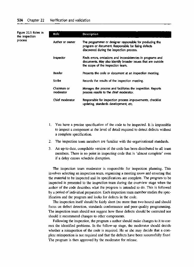
in Hewlett-Packard's development process, Grady and Van Slack (Grady and VanSlack, 1994) suggest six roles, as shown in Figure 22.5. They do not think that read
ing the program aloud is necessary. The same person can take more than one roleso the telm size may vary from one inspection to another. Gilb and Graham suggest that inspectors should be selected to reflect different viewpoints such as testing, end-user and quality management.
The a,:tivities in the inspection process are shown in Figure 22.6. Before a program Inspection process begins, it is essential that:
524 Chapter 22 Verification and validation
Role DescriptionFigure 22.5 Roles inthe inspectionprocess Author or owner
Inspector
Reader
Scribe
Chairman ormoderator
Chief moderator
The programmer or designer responsible for producing theprogram or document Responsible for fixing defectsdiscovered during the inspection process.
Finds errors, omissions and inconsistencies in programs anddocuments. May also identify broader issues that are outsidethe scope of the inspection team.
Presents the code or document at an inspection meeting.
Records the results of the inspection meeting.
Manages the process and facilitates the inspection. Reportsprocess results to the chief moderator.
Responsible for inspection process improvements, checklistupdating, standards development, etc.
1. You have a precise specification of the code to be inspected. It is impossibleto inspect a component at the level of detail required to detect defects withouta complete specification.
2. The inspection team members are familiar with the organisational standards.
3. An up-to-date, compilable version of the code has been distributed to all teammembers. There is no point in inspecting code that is 'almost complete' evenif a delay causes schedule disruption.
The inspection team moderator is responsible for inspection planning. Thisinvolves selecting an inspection team, organising a meeting room and ensuring thatthe material to be inspected and its specifications are complete. The program to beinspected is presented to the inspection team during the overview stage when theauthor of the code describes what the program is intended to do. This is followedby a period of individual preparation. Each inspection team member studies the specification and the program and looks for defects in the code.
The inspection itself should be fairly short (no more than two hours) and shouldfocus on defect detection, standards conformance and poor-quality programming.The inspection team should not suggest how these defects should be corrected norshould it recommend changes to other components.
Following the inspection, the program s author should make changes to it to correct the identified problems. In the follow-up stage, the moderator should decidewhether a reinspection of the code is required. He or she may decide that a complete reinspection is not required and that the defects have been successfully fixed
The program is then approved by the moderator for release.
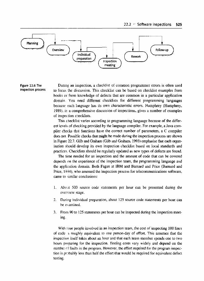
Figure 22.6 Theinspection process
22.2 Software inspections 525
"-....-........,..,.,...,) Glndivid~alpreparation
Dunng an inspection, a checklist of common programmer errors is often usedto focus the discussion. This checklist can be based on checklist examples frombooks or from knowledge of defects that are common in a particular applicationdomain. You need different checklists for different programming languagesbecause each language has its own characteristic errors. Humphrey (Humphrey,1989), in a comprehensive discussion of inspections, gives a number of examplesof inspection checklists.
This checklist varies according to programming language because of the different levels of checking provided by the language compiler. For example, a Java compiler checks that functions have the correct number of parameters, a C compilerdoes not. Possible checks that might be made during the inspection process are shownin Figure 22.7. Gilb and Graham (Gilb and Graham, 1993) emphasise that each organisation should develop its own inspection checklist based on local standards andpractices. Checklists should be regularly updated as new types of defects are found.
The time nel~ded for an inspection and the amount of code that can be covereddepends on the experience of the inspection team, the programming language andthe application domain. Both Fagan at IBM and Barnard and Price (Barnard andPrice, 1994), who assessed the inspection process for telecommunications software,came to ,imilar conclusions:
1. Abo.lt 500 source code statements per hour can be presented during theovervIew stage.
2. During individual preparation, about 125 source code statements per hour canbe examined.
3. From 90 to 125 statements per hour can be inspected during the inspection meeting.
With four people involved in an inspection team, the cost of inspecting 100 linesof codes roughly equivalent to one person-day of effort. This assumes that theinspection itself takes about an hour and that each team member spends one to twohours preparing for the inspection. Testing costs vary widely and depend on thenumber cf faults in the program. However, the effort required for the program inspection is probably less than half the effort that would be required for equivalent defecttesting.

Verification and validation
Fault class Inspection check
Data faults
Control faults
InpuVoutput faults
Interface faults
Storagemanagement faults
Exceptionmanagement faults
Are all program variables initialised before their values areused?Have all constants been named?Should the upper bound of arrays be equal to the size of thearray or Size -17If character strings are used, is a delimiter explicitly assigned?Is there any possibility of buffer overflow?
For each conditional statement, is the condition correct?Is each loop certain to terminate?Are compound statements correctly bracketed?In case statements, are all possible cases accounted for?If a break is required after each case in case statements, hasit been included?
Are all input variables used?Are all output variables assigned a value before they areoutput?can unexpected inputs cause corruption?
Do all function and method calls have the correct number ofparameters?Do formal and actual parameter types match?Are the parameters in the right order?If components access shared memory, do they have the samemodel of the shared memory structure?
If a linked structure is modified, have all links been correctlyreassigned?If dynamic storage is used, has space been allocatedcorrectly?Is space explicitly de-allocated after it is no longer required?
Have all possible error conditions been taken into account?
Some organisations (Gilb and Graham, 1993) have now abandoned componenttesting in favour of inspections. They have found that program inspections are soeffective at finding errors that the costs of component testing are not justifiable.These organisations found that inspections of components, combined with systemtesting, were the most cost-effective V & V strategy. As I discuss later in the chapter, this approach is used in the Cleanroom software development process.
The introduction of inspections has implications for project management.Sensitive management is important if inspections are to be accepted by softwaredevelopment teams. Program inspection is a public process of error detection compared with the more private component testing process. Inevitably, mistakes thatare made by individuals are revealed to the whole programming team. Inspection
team leadersJl1lust be trained to manage the process carefully and to develop a culture that provides support without blame when errors are discovered.
As an organisation gains experience of the inspection process, it can use the resultsof inspe'~tions to help with process improvement. Inspections are an ideal way tocollect data on the type of defects that occur. The inspection team and the authorsof the code that was inspected can suggest reasons why these defects were introduced. W'herever possible, the process shouXd then be modified to eliminate the reasons for defects so they can be avoided in future systems.
22.3 AutornatE!d static analysis--- ---------------
InspectIOns are one form of static analysis--you examine the program without executing it. As I discussed, inspections are often driven by checklists of errors andheuristics that identify common errors in different programming languages. For someerrors and heuristics, it is possible to automate the process of checking programsagainst this list, which has resulted in the development of automated static analysers for Jifferent programming languages.
Static analysers are software tools that scan the source text of a program and detectpossible faults and anomalies. They parse the program text and thus recognise thetypes of stateIDi~nts in the program. They can then detect whether statements are wellformed. make inferences about the control flow in the program and, in many cases,compute the sell of all possible values for program data. They complement the errordetection facililies provided by the languagt~ compiler. They can be used as part ofthe insptxtion process or as a separate V & V process activity.
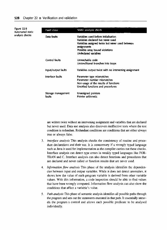
The Intention of automatic static analysis is to draw an inspector's attention toanomalit:s in the program, such as variables that are used without initialisation, variables that are unused or data whose value could go out of range. Some of the checksthat can Je detected by static analysis are shown in Figure 22.8. Anomalies are oftena result of programming errors or omissions, so they highlight things that could gowrong when the program is executed. However, you should understand that theseanomalies are not necessarily program faults. They may be deliberate or may haveno adverse consequences.
The stages involved in static analysis include:
I. Control flow analysis This stage identifies and highlights loops with multipleexit or entry points and unreachable code. Unreachable code is code that is surroun.ded by unconditional goto statements or that is in a branch of a conditionalstatement 'where the guarding condition can never be true.
2. Data use analysis This stage highlights how variables in the program are used.It df:tects variables that are used without previous initialisation, variables that
528 Chapter 22 Ii Verification and validation
Fault class Static analysis checkFigure 228Automated staticanalysis checks Data faults
Control faults
Input/output faults
Interface faults
Storage managementfaults
Variables used before initialisationVariables declared but never usedVariables assigned twice but never used betweenassignmentsPossible array bound violationsUndeclared variables
Unreachable codeUnconditional branches into loops
Variables output twice with no intervening assignment
Parameter type mismatchesParameter number mismatchesNon-usage of the results of functionsUncalled functions and procedures
Unassigned pointersPointer arithmetic
are written twice without an intervening assignment and variables that are declaredbut never used. Data use analysis also discovers ineffective tests where the testcondition is redundant. Redundant conditions are conditions that are either alwaystrue or always false.
3. Interface analysis This analysis checks the consistency of routine and procedure declarations and their use. It is unnecessary if a strongly typed languagesuch as Java is used for implementation as the compiler carries out these checks.Interface analysis can detect type errors in weakly typed languages like FORTRAN and C. Interface analysis can also detect functions and procedures thatare declared and never called or function results that are never used.
4. Information flow analysis This phase of the analysis identifies the dependencies between input and output variables. While it does not detect anomalies, itshows how the value of each program variable is derived from other variablevalues. With this information, a code inspection should be able to find valuesthat have been wrongly computed. Information flow analysis can also show theconditions that affect a variable's value.
5. Path analysis This phase of semantic analysis identifies all possible paths throughthe program and sets out the statements executed in that path. It essentially unravels the program s control and allows each possible predicate to be analysedindividually.

223 r;;; Automated static analysis 529----------.__._---------
Stall:: analysers are partIcularly valuablt~ when a programming language such as
C is used. C does not have strict type rules, and the checking that the C compiler
can do •s limited. Therefore, it is easy for programmers to make mistakes, and the
static aulysis tool can automatIcally discover some of the resulting program faults.This is particularly important when C (and to a lesser extent, C++) is used for crit
ical sy,\I~ms development. In this case, static analysis can discover a large number
of pater tial ermrs and can significantly reduce testing costs
Then: IS no doubt that, for languages such as C, static analysis is an effective technique for discovering program errors. It compensates for weaknesses in the program
ming language design. However, the designers of modem programming languages suchas Java have rt:moved some error-prone language features. All variables must be ini
tialised. there are no goto statements so unreachable code is less likely to be createdaCCIdentally, and storage management is automatic. This approach of error avoidance
rather than errm detection is more effective in improving program reliability. Althoughstatic analysers for Java are available, they are not widely used. It is not clear whether
the number of errors detected justifies the time required to analyse their output.
Thereiore, to illustrate static analysis I use a small C program rather than a Javaprogran·. Unix and Linux systems mclude a static analyser called LINT for C pro
grams. L [NT provides static checking, which is equivalent to that provided by the
compiler in a strongly typed language such as Java. An example of the output pro
duced by LINT is shown in Figure 22.9. In this transcript of a Unix terminal session, commands are shown in italics. The first command (line 138) lists the
(nonsensical) program. It defines a function with one parameter, called printarray,and then calls this function with three parameters. Variables i and c are declaredbut are never aSSIgned values. The value returned by the functlon IS never used.
The iHle numbered 139 shows the C compilation of thIS program with no errors
reported by the C compiler. This is followed by a call of the LINT static analyser,
which detects and reports program errors.The qatic analyser shows that the variables;: and i have been used but not ini
tialised. and that printarray has been called with a difterent number of arguments
than are ceclared. It also identifies the inconsistent use of the first argument in printarray and the fact that the functIOn value is never used.
Tool-based analysis cannot replace inspections, as there are some types of errorthat static analysers cannot detect. For example, they can detect uninitialised variables, but they cannot detect initialisations that are Incorrect. In weakly typed languages such as C, static analysers can detect functions that have the wrong numbers
and types of arguments, but they cannot detec!. situations where an incorrect argument of the conect type has been passed to a functIOn.
To address some of these problems, static analysers such as LCLint (Orcero, 2000;Evans anc Larochelle, 2002) support the use of annotations where users define con
straints as stylised comments in the program. These constraints allow a programmer to specify that variables In a function should not be changed, the globalvariables Jsed, and so on. The static analyser can then check the program againstthese com traints and highlight code s~cllons that appear to be Iflcorrect.

530 Chapter 22 'il Verification and validation
Figure 22.9 LINTstatic analysis 138% more lincex.c
#:include <stdio.h>printarray (Anarray)int Anarray;{printf("%d",Anarray);}main 0{int Anarray[S]; int i; char c;printarray (Anarray, i, c);printarray (Anarray) ;}
139% cc lint_ex.c140% lint linCex.c
linCex.c(10): warning: c may be used before setlinCex.c(10): warning: i may be used before setprintarray: variable #: of args. lincex.c(4) :: IinCex.c(10)printarray, argo 1 used inconsistently IinCex.c(4) :: lincex.c(10)printarray, argo 1 used inconsistently linCex.c(4) :: Iincex.c(11)printf returns value which is always ignored
22.4 Verification and formal methods
Formal methods of software development are based on mathematical representations of the software, usually as a formal specification. These formal methods aremainly concerned with a mathematical analysis of the specification; with transformingthe specification to a more detailed, semantically equivalent representation; or withformally verifying that one representation of the system is semantically equivalentto another representation.
You can think of the use of formal methods as the ultimate static verificationtechnique. They require very detailed analyses of the system specification and theprogram, and their use is often time consuming and expensive. Consequently, theuse of formal methods is mostly confined to safety- and security-critical softwaredevelopment processes. The use of formal mathematical specification and associated verification was mandated in UK defence standards for safety-critical software(MOD, 1995).
Formal methods may be used at different stages in the V & V process:

22.4 Verification and formal methods 531
1. A formal specification of the system may be developed and mathematically analysed for inconsistency. This technique is effective in discovering specificationerrors and omissions, as discussed in Chapter 10.
2. You can formally verify, using mathematical arguments, that the code of a software system is consistent with its specification. This requires a formal specification and is effective in discovering programming and some design errors.A transformational development process where a formal specification is transformed through a series of more detailed representations or a Cleanroom process may be used to support the formal verification process.
The argument for the use of formal specification and associated program verification 1'. that formal specification forces a detailed analysis of the specification. Itmay reveal potential inconsistencies or omissions that might not otherwise be discovered until the system is operational. Formal verification demonstrates that thedeveloped program meets its specification so implementation errors do not compromise dependability
The argument against the use of formal specification is that it requires specialisednotations. These can only be used by specially trained staff and cannot be understood by domain experts. Hence, problems with the system requirements can be concealed by fomlality. Software engineers cannot recognise potential difficulties withthe requirements because they don't understand the domain; domain experts cannot find these problems because they don't understand the specification. Althoughthe specification may be mathematically consistent, it may not specify the systemproperties that are really required.
Verifying a nontrivial software system takes a great deal of time and requiresspeciali~,ed tools such as theorem provers and mathematical expertise. It is therefore an extremely expensive process and, as the system size increases, the costs offormal verificaltion increase disproportionately. Many people therefore think: that formal verification is not cost-effective. The same level of confidence in the systemcan be achieved more cheaply by using other validation techniques such as inspections and system testing.
It is sometimes claimed that the use of formal methods for system developmentleads to more reliable and safer systems. There is no doubt that a fonnal systemspecificction is less likely to contain anomalies that must be resolved by the system designer. However, formal specification and proof do not guarantee that thesoftware will be reliable in practical use. The reasons for this are:
1. The specification may not reflect the real requirements of system users. Lutz(Lutz, 1993) discovered that many failures experienced by users were a consequence of specification errors and omissions that could not be detected byfornlal system specification. Furthermore, system users rarely understand formal notations so they cannot read the fOIDlal specification directly to find errorsand omissions.
532 Chapter 22 ' Verification and validation
2. The proof may contain errors. Program proofs are large and complex, so, likelarge and complex programs, they usually contain errors.
3. The proof may assume a usage pattern which is incorrect. If the system is notused as anticipated, the proof may be invalid.
In spite of their disadvantages, my view (discussed in Chapter 10) is that formalmethods have an important role to play in the development of critical software systems. Formal specifications are very effective in discovering specification problemsthat are the most common causes of system failure. Formal verification increasesconfidence in the most critical components of these systems. The use of formalapproaches is increasing as procurers demand it and as more and more engineersbecome familiar with these techniques.
22.4.1 Cleanroom software development
Formal methods have been integrated with a number of software development processes. In the B method (Wordsworth, 1996) a formal specification is transformedthrough a series of correctness-preserving transformations to a program. SDL(Mitschele-Thiel, 2001) is used for telecommunications systems development andVDM (Jones, 1986) and Z (Spivey, 1992) have been used in waterfall-type processes.Another well-documented approach that uses formal methods is the Cleanroom development process. Cleanroom software development (Mills, et al., 1987; Cobb and Mills,1990; Linger, 1994; Prowell, et al., 1999) is a software development philosophy thatuses formal methods to support rigorous software inspection.
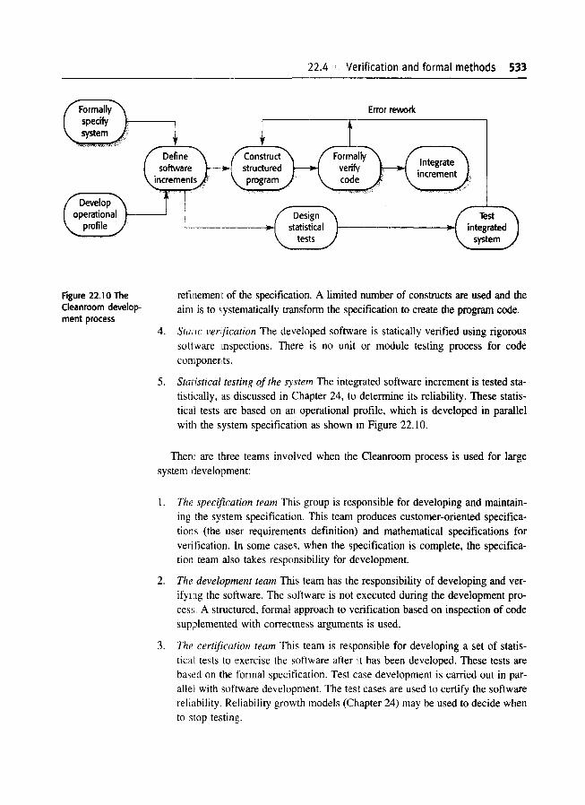
A model of the Cleanroom process is shown in Figure 22.10. The objective ofthis approach to software development is zero-defect software. The name'Cleanroom was derived by analogy with semiconductor fabrication units wheredefects are avoided by manufacturing in an ultra-clean atmosphere. Cleanroom development is particularly relevant to this chapter because it has replaced the unit testing of system components by inspections to check the consistency of thesecomponents with their specifications.
The Cleanroom approach to software development is based on five key strategies:
1. Formal specification The software to be developed is formally specified. A statetransition model that shows system responses to stimuli is used to express thespecification.
2. Incremental development The software is partitioned into increments that aredeveloped and validated separately using the Cleanroom process. These increments are specified, with customer input, at an early stage in the process.
3. Structured programming Only a limited number of control and data abstractionconstructs are used. The program development process is a process of stepwise
22.4 Verification and formal methods 533
Error rework
--.---.-----..J
Define )-software
increments,'
Figure 22.10 TheCleanroom development process
4.
5.
refinemenlt of the specification. A limited number of constructs are used and theaim is to systematically transform the specification to create the program code.
StatiC verification The developed software is statically verified using rigoroussoftware mspections. There is no unit or module testing process for codecomponents.
Statistical testing of the system The integrated software increment is tested statistically, as discussed in Chapter 24, Ito determine its reliability. These statistical tests are based on an operational profile, which is developed in parallelwith the system specification as shown m Figure 22.10.
There are three teams involved when the Cleanroom process is used for largesystem development:
1. The specification team This group is responsible for developing and maintaining the system specification. This team produces customer-oriented specifications (the user requirements definition) and mathematical specifications forverification. In some cases, when the specification is complete, the specification team also takes responsibility for dt:velopment.
2. The development team This tearn has the responsibility of developing and verifymg the software. The software is not executed during the development process. A structured, formal approach to verification based on inspection of codesupplemented with correctness arguments is used.
3. The certification team This team is responsible for developing a set of statistical tests to exercise the software after it has been developed. These tests arebas(~d on the formal specification. Test case development is carried out in parallel with software development. The tl~st cases are used to certify the softwarereliability. Reliability growth models (Chapter 24) may be used to decide whento stop testing.
Verification and validation
Use of the Cleanroom approach has generally led to software with very few errors.Cobb and Mills discuss several successful Cleanroom development projects that hada uniformly low failure rate in delivered systems (Cobb and Mills, 1990). The costsof these projects were comparable with other projects that used conventional development techniques.
The approach to incremental development in the Cleanroom process is to delivercritical customer functionality in early increments. Less important system functionsare included in later increments. The customer therefore has the opportunity to try
these critical increments before the whole system has been delivered. If requirements problems are discovered, the customer feeds back this information to the development team and requests a new release of the increment.
As with extreme programming, this means that the most important customer functions receive the most validation. As new increments are developed, they are combined with the existing increments and the integrated system is tested. Therefore,existing increments are retested with new test cases as new system increments areadded.
Rigorous program inspection is a fundamental part of the Cleanroom process. Astate model of the system is produced as a system specification. This is refined througha series of more detailed system models to an executable program. The approachused for development is based on well-defined transformations that attempt to preserve the correctness at each transformation to a more detailed representation. Ateach stage, the new representation is inspected, and mathematically rigorous arguments are developed that demonstrate that the output of the transformation is consistent with its input.
The mathematical arguments used in the Cleanroom process are not, however,formal proofs of correctness. Formal mathematical proofs that a program is correctwith respect to its specification are too expensive to develop. They depend on usingknowledge of the formal semantics of the programming language to construct theories that relate the program and its formal specification. These theories must then beproven mathematically, often with the assistance of large and complex theorem-proverprograms. Because of their high cost and the specialist skills that are needed, proofsare usually developed only for the most safety- or security-critical applications.
Inspection and formal analysis has been found to be very effective in theCleanroom process. The vast majority of defects are discovered before executionand are not introduced into the developed software. Linger (Linger, 1994) reportsthat, on average, only 2.3 defects per thousand lines of source code were discovered during testing for Cleanroom projects. Overall development costs are not increasedbecause less effort is required to test and repair the developed software.
Selby et aI., (Selby, et aI., 1987), using students as developers, carried out anexperiment that compared Cleanroom development with conventional techniques.They found that most teams could successfully use the Cleanroom method. The programs produced were of higher quality than those developed using traditional techniques-the source code had more comments and a simpler structure. More of theCleanroom teams met the development schedule.
Chapter 22 ' Further Reading 535--------_.
Cleanroom development works when practised by skilled and committed engineers.Reports of the success of the Cleanroom approach in industry have mostly, though notexclusively, come from people already committed to it. We don't know whether thisprocess can be transferred effectively to other types of software development organisations. These organisations may have less committed and less skilled engineers.Transferring the Cleanroom approach or, indeed, any other approach where formalmethods are used, to less technically advanctxt organisations still remains a challenge.
KEY POINTS
Verification and validation are not the same thing. Verification is intended to show that aprogram meets its specification. Validation is intended to show that the program does whatthe user requires.
Test plans should include a description of the items to be tested. the testing schedule, theprocedures for managing the testing process, the hardwalre and software requirements, andany testing problems that arE! likely to arise.
Static verification techniques involve examination and analysis of the program source codeto detect errors. They should be used with program testing as part of the V & V process.
Program inspections are effe(:tive in finding program errors. The aim of an inspection is tolocate faults. A fault checklist should drive the inspection process.
In a program inspection, a small team systematically checks the code. Team membersinclude a team leader or moderator. the author of the code. a reader who presents the codeduring the inspection and a t!!ster who considers the code from a testing perspective.
Static analysers are software tools that process a program source code and draw attentionto anomalies such as unused code sections and uninitialised variables. These anomaliesmay be the result of faults in the code.
Cleanroom software development relies on static techniques for program verification andstatistical testing for system reliability certification. It has been successful in producingsystems that have a hi~rh level of reliability.
FURTHER READING
Software Quality Assurance: Frorn Theory to Implementation. This book provides good generalbackground reading on verification and validation, with a particularly good chapter on reviews andinspections. (D. Galin, 2001f, Addison-Wesley.)
536 Chapter 22 . Verification and validation
'Software inspection'. A special issue of a journal that contains a number of articles on programinspection, including a discussion on using this technique with object-oriented development. (IEEESoftware, 20(4), july/August 2003.)
'Software debugging, testing and verification'. This is a general article on verification and validationand one of the few articles that addresses both testing and static verification techniques. (B.Hailpern and P. Santhanam, IBM Systems Journal, 41(1), january 2002.)
Cleanroom Software Engineering: Technology and Process. A good book on the Cleanroomapproach that has sections on the basics of the technique, the process and a practical case study.(S. j. Powell, et aI., 1999, Addison-Wesley.)
EXERCISES -----22.1 Discuss the differences between verification and validation. and explain why validation is a
particularly difficult process.
22.2 Explain why it is not necessary for a program to be completely free of defects before it isdelivered to its customers. To what extent can testing be used to validate that the program isfit for its purpose?
22.3 The test plan in Figure 22-4 has been designed for custom systems that have a separaterequirements document. Suggest how the test plan structure might be modified for testingshrink-wrapped software products.
22.4 Explain why program inspections are an effective technique for discovering errors in aprogram. What types of error are unlikely to be discovered through inspections?
22.5 Suggest why an organisation with a competitive, elitist culture would probably find it difficultto introduce program inspections as a V & V technique.
22.6 Using your knowledge of java, CH, Cor some other programming language. derive achecklist of common errors (not syntax errors) that could not be detected by a compiler butthat might be detected in a program inspection.
22.7 Produce a list of conditions that could be detected by a static analyser for Java, c++ oranother programming language that you use. Comment on this list compared to the list givenin Figure 22.7.
22.8 Explain why it may be cost-effective to use formal methods in the development of safety·critical software systems. Why do you think that some developers of this type of system areagainst the use of formal methods?
22.9 A manager decides to use the reports of program inspections as an input to the staffappraisal process. These reports show who made and who discovered program errors. Is thisethical managerial behaviour? Would it be ethical if the staff were informed in advance thatthis would happen? What difference might it make to the inspection process?
22.10 One approach that is commonly adopted to system testing is to test the system until thetesting budget is exhausted and then deliver the system to customers. Discuss the ethics ofthis approach.

I
23JSOlftware testing
ObjectivesThe objective of this chapter is to describe the processes of softwaretesting and introduce a range of testing techniques. When you haveread the chapter, you will:
• understand the distinctions between validation testing and defecttesting;
• understand the principles of system testing and component testing;
• understand three strategies that may be used to generate systemtest cases;
• understand the essential characteristics of software tools thatsupport test automation.
Contents23.1 System testing
23.2 Component testing
23.3 Test case design
23.4 Test automation

538 Chapter 23 ~1 Software testing
In Chapter 4, I discussed a general testing process that started with the testing ofindividual program units such as functions or objects. These were then integratedinto sub-systems and systems, and the interactions of these units were tested.Finally, after delivery of the system, the customer may carry out a series of acceptance tests to check that the system performs as specified.
This model of the testing process is appropriate for large system developmentbut for smaller systems, or for systems that are developed through scripting or reuse,there are often fewer distinct stages in the process. A more abstract view of software testing is shown in Figure 23.1. The two fundamental testing activities arecomponent testing-testing the parts of the system-and system testing-testing thesystem as a whole.
The aim of the component testing stage is to discover defects by testing individual program components. These components may be functions, objects orreusable components as described in Chapter 19. During system testing, these components are integrated to form sub-systems or the complete system. At this stage,system testing should focus on establishing that the system meets its functional andnon-functional requirements, and does not behave in unexpected ways. Inevitably,defects in components that have been missed during earlier testing are discoveredduring system testing.
As I explained in Chapter 22, the software testing process has two distinct goals:
1. To demonstrate to the developer and the customer that the software meets itsrequirements. For custom software, this means that there should be at least onetest for every requirement in the user and system requirements documents. Forgeneric software products, it means that there should be tests for all of the system features that will be incorporated in the product release. As discussed inChapter 4, some systems may have an explicit acceptance testing phase wherethe customer formally checks that the delivered system conforms to its specification.
2. To discover faults or defects in the software where the behaviour of the software is incorrect, undesirable or does not conform to its specification. Defecttesting is concerned with rooting out all kinds of undesirable system behaviour,such as system crashes, unwanted interactions with other systems, incorrect computations and data corruption.
The first goal leads to validation testing, where you expect the system to perform correctly using a given set of test cases that reflect the system s expected use.The second goal leads to defect testing, where the test cases are designed to expose
Systemtesting
Figure 23.1 Testingphases I Comp?nent I
. testing .------lI.~1'-----.......I
software developer Independent testing team

Chapter 23 ~ Software testing 539-----------_.__._----------
Design testcases
Figure 23.2 A modelof the softwaretesting process
Prepare t,estdata
defects. The test cases can be deliberately obscure and need not reflect how the system is normally ILIsed. For validation testing, a successful test is one where the system performs correctly. For defect testing, a successful test is one that exposes adefect that causes the system to perform incorrectly.
Testing cannot demonstrate that the software is free of defects or that it will behaveas specifii::d in every circumstance. It is always possible that a test that you haveoverlooked could discover further problems with the system. As Edsger Dijkstra, aleading early figlJre in the development of software engineering, eloquently stated(Dijkstra, et al., 1972), 'Testing can only show the presence of errors, not their absence.
Overall, therefore, the goal of software testing is to convince system developersand customers that the software is good enough for operational use. Testing is aprocess intended to build confidence in the software.
A general model of the testing process is shown in Figure 23.2. Test cases arespecifications of the inputs to the test and the expected output from the system plusa statement of what is being tested. Test data are the inputs that have been devisedto test the system. Test data can sometimes be generated automatically. Automatictest case g,,:neration is impossible. The output of the tests can only be predicted bypeople who understand what the system should do.
Exhausl ive testing, where every possible program execution sequence is tested,is impossible. Testing, therefore, has to be based on a subset of possible test cases.Ideally, software companies should have policies for choosing this subset rather thanleave this 10 the development team. These policies might be based on general testing policic;, such as a policy that all program statements should be executed at leastonce. Alternatively. the testing policies may bi:: based on experience of system usageand may focus 011 testing the features of the operational system. For example:
I. All sy:item functions that are accessed through menus should be tested.
2. Combinations of functions (e.g., text formatting) that are accessed through thesame menu must be tested.
3. Where user mput is provided, all functions must be tested with both correctand incorrect input.
It is clear from experience with major software products such as word processors or spreadsheets that comparable guidelines are normally used during producttesting. When features of the software are used in isolation, they normally work.
540 Chapter 23 :; Software testing
Problems arise, as Whittaker explains (Whittaker, 2(02), when combinations of features have not been tested together. He gives the example of how, in a commonlyused word processor, using footnotes with multicolurnn layout causes incorrect layout of the text.
As part of the V & V planning process, managers have to make decisions onwho should be responsible for the different stages of testing. For most systems, programmers take responsibility for testing the components that they have developed.Once this is completed, the work is handed over to an integration team, which integrates the modules from different developers, builds the software and tests the system as a whole. For critical systems, a more formal process may be used whereindependent testers are responsible for all stages of the testing process. In criticalsystem testing, the tests are developed separately and detailed records are maintainedof the test results.
Component testing by developers is usually based on an intuitive understandingof how the components should operate. System testing, however, has to be basedon a written system specification. This can be a detailed system requirements specification, as discussed in Chapter 6, or it can be a higher-level user-oriented specification of the features that should be implemented in the system. A separate teamis normally responsible for system testing. As discussed in Chapter 4, the systemtesting team works from the user and system requirements documents to developsystem-testing plans (see Figure 4.10).
Most discussions of testing start with component testing and then move on to system testing. I have deliberately reversed the order of discussion in this chapterbecause more and more software development involves integrating reusable components and configuring and adapting existing software to meet specific requirements.All testing in such cases is system testing, and there is no separate component testing process.
23.1 System testing
System testing involves integrating two or more components that implement system functions or features and then testing this integrated system. In an iterative development process, system testing is concerned with testing an increment to bedelivered to the customer; in a waterfall process, system testing is concerned withtesting the entire system.
For most complex systems, there are two distinct phases to system testing:
1. Integration testing. where the test team have access to the source code of thesystem. When a problem is discovered, the integration team tries to find thesource of the problem and identify the components that have to be debugged.Integration testing is mostly concerned with finding defects in the system.
23.1 91 System testing 541
2. Release testlng, where a version of the system that could be released to usersis tested. Here, the test team is concerned with validating that the system meetsits requireIDi~nts and with ensuring that the system is dependable. Release testing is usually 'black-box' testing where the test team is simply concemed withdemonstrating that the system does or does not work properly. Problems arereported to 1he development team whose job is to debug the program. Wherecustomers alre involved in release testing, this is sometimes called acceptancetesting. If the release is good enough, the customer may then accept it for use.
Fundamentally, you can think of integration testing as the testing of incompletesystems composed of clusters or groupings of system components. Release testingis concerned with testing the system release that is intended for delivery to customers. ]\aturally, these overlap, especially when incremental development is usedand the system to be released is incomplete. Generally, the priority in integrationtesting is '0 discover defects in the system and the priority in system testing, is tovalidate that the system meets its requirements. However, in practice, there is somevalidation testing and some defect testing during both of these processes.
23.1.1 Integra~!on tE!st_in--"'g'-- .
The process of system integration involves building a system from its components(see Chapter 29) and testing the resultant system for problems that arise from component interactions. The components that are integrated may be off-the-shelf components, reusable components that have been adapted for a particular system or newlydeveloped components. For many large systems, all three types of components arelikely to be used. Integration testing checks that these components actually worktogether, are called correctly and transfer the right data at the right time across theirinterfaces.
System integration involves identifying clusters of components that deliver somesystem functionallity and integrating these by adding code that makes them work together.Sometimes, the overall skeleton of the system is developed first, and components areadded to il. This is called top-down integration. Alternatively, you may first integrateinfrastructure components that provide common services, such as network anddatabase access, then add the functional components. This is bottom-up integration.In practice .. for many systems, the integration strategy is a mixture of these, with bothinfrastructure components and functional components added in increments. In bothtop-down and bottom-up integration, you usually have to develop additional code tosimulate other components and allow the system to execute.
A major problem that arises during integration testing is localising errors. Thereare compj,~x interactions between the system components and, when an anomalousoutput is discovered, you may find it hard to identify where the error occurred. Tomake it easier to locate errors, you should always use an incremental approach tosystem integration and testing. Initially, you should integrate a minimal system

542 Chapter 23 " Software testing
Figure 23.3Incrementalintegration testing
Test sequence 1 Test sequence 2 Test sequence 3
•
configuration and test this system. You then add components to this minimal configuration and test after each added increment.
In the example shown in Figure 23.3, A, B, C and D are components and n toT5 are related sets of tests of the features incorporated in the system. n, T2 andT3 are first run on a system composed of component A and component B (the minimal system). If these reveal defects, they are corrected. Component C is integratedand n, T2 and T3 are repeated to ensure that there have not been unexpected interactions with A and B. If problems arise in these tests, this probably means that theyare due to interactions with the new component. The source of the problem is localised,thus simplifying defect location and repair. Test set T4 is also run on the system.Finally, component D is integrated and tested using existing and new tests (T5).
When planning integration, you have to decide the order of integration of components. In a process such as XP, the customer is involved in the development process and decides which functionality should be included in each system increment.Therefore, system integration is drivenby customer priorities. In other approachesto development when off-the-shelf components and specially developed componentsare integrated, the customer may not be involved and the integration team decideson the integration priorities.
In such cases, a good rule of thumb is to integrate the components that implement the most frequently used functionality first. This means that the componentsthat are most used receive the most testing. For example, in the library system, LIBSYS, you should start by integrating the search facility so that, in a minimal system, users can search for documents that they need. You should then add thefunctionality to allow users to download a document, then progressively add thecomponents that implement other system features.
Of course, reality is rarely as simple as this model suggests. The implementation of system features may be spread across a number of components. To test a

23 1 System testing 543
new feature, you may have to integrate several different components. The testingmay revleal errors in the interactions between these individual components and otherparts of the system. Repairing errors may be difficult because a group of components that impl,ement the system feature may have to be changed. Furthermore, integrating and testing a new component can change the pattern of already testedcomponent interactions. Errors may be revealed that were not exposed in the testsof the simpler configuration.
Thes(: problems mean that when a new increment is integrated, it is importantto rerun the tests for previous increments as well as the new tests that are requiredto verify the new system functionality. Rerunning an existing set of tests is calledregression testing. If regression testing exposes problems, then you have to checkwhether these are problems in the previous increment that the new increment hasexposed or whether these are due to the added increment of functionality
Regression testing is clearly an expensive process and is impractical without someautomate:d support. In extreme programming, as discussed in Chapter 17, all testsare written as executable code where the test input and the expected outputs arespecified and automatically checked. When used with an automated testing framework such as JUnit (Massol and Husted, 2003), this means that tests can be automatically rerun. It is a basic principle of extreme programming that the completetest set is executed whenever new code is integrated and that this new code is notaccepted until all tests run successfully.
23.1.2 Releas.~ test_in""'g"-- _
Release testing is the process of testing a release of the system that will be distributed to customers. The primary goal of this process is to increase the supplier'sconfidence that the system meets its requirements. If so, it can be released as a product or delivered to the customer. To demonstrate that the system meets its requirements, you havle to show that it delivers the specified functionality, performanceand dependability, and that it does not fail during normal use.
Release testing is usually a black-box testing process where the tests are derivedfrom the system specification. The system is treated as a black box whosebehaviour can only be determined by studying its inputs and the related outputs.Another name for this is functional testing because the tester is only concerned withthe functionality and not the implementation of the software.
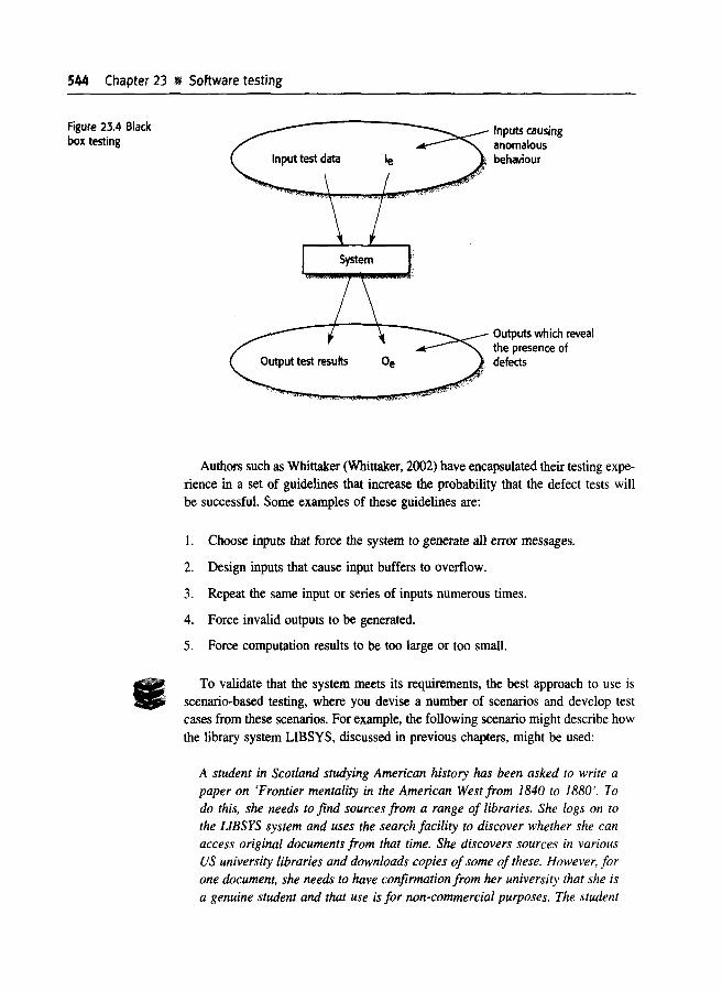
Figure 23.4 illustrates the model of a system that is assumed in black-box testing. The tester presents inputs to the component or the system and examines thecorresponding outputs. If the outputs are not those predicted (i.e., if the outputs arein set 0,) then the test has detected a problem with the software.
When testing system releases, you should try to 'break' the software by choosing test cases that are in the set Ie in Figure 23.4. That is, your aim should be toselect inputs that have a high probability of generating system failures (outputs inset Oe)' You use previous experience of what are likely to be successful defect testsand testing guid,elines to help you make your choice.
544 Chapter 23 III Software testing
Figure 23.4 Blackbox testing
Inputs causinganomalousbehiJIiour
Outputs which revealthe presence ofdefects
•
Authors such as Whittaker (Whittaker, 2(02) have encapsulated their testing experience in a set of guidelines that increase the probability that the defect tests willbe successful. Some examples of these guidelines are:
1. Choose inputs that force the system to generate all error messages.
2. Design inputs that cause input buffers to overflow.
3. Repeat the same input or series of inputs numerous times.
4. Force invalid outputs to be generated.
5. Force computation results to be too large or too small.
To validate that the system meets its requirements, the best approach to use isscenario-based testing, where you devise a number of scenarios and develop testcases from these scenarios. For example, the following scenario might describe howthe library system LIBSYS, discussed in previous chapters, might be used:
A student in Scotland studying American history has been asked to write apaper on 'Frontier mentality in the American West from 1840 to 1880'. Todo this, she needs to find sources from a range of libraries. She logs on tothe LIBSYS system and uses the search facility to discover whether she canaccess original documents from that time. She discovers sources in variousUS university libraries and downloads copies of some of these. However, forone document, she needs to have confirmation from her university that she isa genuine student and that use is for non-commercial purposes. The student
23 1 .. System testing 545
then Itses the facility in LIBSYS that can request such permission and registers lier request. If granted, the document will be downloaded to the registered library's server and printed for her. She receives a message fromLIBS YS telling her that she will receive an e-mail message when the printed
document is available for collection.
From this scenario, it is possible to device a number of tests that can be appliedto the proposed release of LIBSYS:
1. Te~t the login mechanism using correct and incorrect logins to check that validusers are accepted and invalid users are rejected.
2. Te~.t the search facility using queries against known sources to check that thesea['ch mf::chanism is actually finding documents.
3. Te~ l the system presentation facility to check that information about documentsis clisplayed properly.
4. Te~t the mechanism to request permission for downloading.
5. Te~t the e-mail response indicating that the downloaded document is available.
For each of these tests, you should design a set of tests that include valid andinvalid inputs and that generate valid and invalid outputs. You should also organise scenario-based testing so that the most likely scenarios are tested first, and unusualor exceptional scenarios considered later, so your efforts are devoted to those partsof the s)lstem that receive the most use.
If you have used use-cases to describe the system requirements, these use-casesand associated sequence diagrams can be a basis for system testing. The use-casesand sequence charts can be used during both integration and release testing. To illustrate thi:;, I use an example from the weather station system described in Chapter 14.
Figure 23.5 shows the sequence of operations in the weather station when it respondsto a request to collect data for the mapping system. You can use this diagram toidentify operations that will be tested and to help design the test cases to executethe test~. Therefore issuing a request for a report will result in the execution of thefollowing thread of methods:
Com msController:request --> WeatherStation:report --> WeatherData:summarise
The :iequence diagram can also be used to identify inputs and outputs that haveto be created for the test:
1. An Illput of a request for a report should have an associated acknowledgementand a report should ultimately be returned from the request. During the testing. you should create summarised data that can be used to check that the reportis correctly organised.

546 Chapter 23 llt Software testing
Figure 23.5 Collectweather datasequence chart
:CommsController I:WeatherStation I I :WeatherData Irequest (report)
,,,acknowledge 0 ·,
report 0 ··,summarise 0,·~~~~~~~~]
,··. ··,·,,·, send (report)..:.reply (report) ···,·acknowledge 0
,,,,,·
2. An input request for a report to WeatherStation results in a summarised reportbeing generated. You can test this in isolation by creating raw data correspondingto the summary that you have prepared for the test of CommsController andchecking that the WeatherStation object correctly produces this summary.
3. This raw data is also used to test the WeatherData object.
Of course, I have simplified the sequence diagram in Figure 23.5 so that it doesnot show exceptions. A complete scenario test must also take these into accountand ensure that objects correctly handle exceptions.
23.1.3 Performance testing
Once a system has been completely integrated, it is possible to test the system foremergent properties (see Chapter 2) such as performance and reliabilityPerformance tests have to be designed to ensure that the system can process its intendedload. This usually involves planning a series of tests where the load is steadily increaseduntil the system performance becomes unacceptable.
As with other types of testing, performance testing is concerned both withdemonstrating that the system meets its requirements and discovering problems anddefects in the system. To test whether performance requirements are beingachieved, you may have to construct an operational profile. An operational profileis a set of tests that reflect the actual mix of work that will be handled by the system. Therefore, if 90% of the transactions in a system are of type A, 5% of type Band the remainder of types C, D, and E, then you have to design the operational
23 2 • Component testing 547
profile so that the vast majority of tests are of type A. Otherwise, you will not getan accurate tl~st of the operational performance of the system. I discuss operationalprofiles andltheir use in reliability testing in Chapter 24.
ThIS approach, of course, is not necessarily the best approach for defect testing.As I discuss later, experience has shown that an effective way to discover defectsis to design tests around the limits of the system. In performance testing, this meansstressing the system (hence the name stress testing) by making demands that areoutside the design limits of the software.
For example, a transaction processing system may be designed to process up to300 transactions per second; an operating system may be designed to handle up to1,000 :;eparate terminals. Stress testing continues these tests beyond the maximumdesign load of the system until the system fails. This type of testing has two functions:
I. It tests the failure behaviour of the system. Circumstances may arise throughan unexpected combination of events where the load placed on the system exceedsthe maximum anticipated load. In these circumstances, it is important that system failure should not cause data corruption or unexpected loss of user services. Stress testing checks that overloading the system causes it to 'fail-soft'rather than collapse under its load.
2. It stresses the system and may cause defects to come to light that would notnormally be discovered. Although it can be argued that these defects areunlikely to cause system failures in normal usage, there may be unusual combinations of normal circumstances that the stress testing replicates.
Stress testing is particularly relevant to distributed systems based on a networkof processors. These systems often exhibit severe degradation when they are heavily loaded. The network becomes swamped with coordination data that the different processes must exchange, so the processes become slower and slower as theywait for the required data from other processes.
23.2 Compon1ent testing
Component testing (sometimes called unit testing) is the process of testing individualcomponents in the system. This is a defect testing process so its goal is to exposefaults in these components. As I discussed in the introduction, for most systems,the developers of components are responsible for component testing.
There are different types of component that may be tested at this stage:
l. Individual functions or methods within an object
2. Object classes that have several attributes and methods

Software testing
WeatherStation
identifier
reportWeather 0calibrate Onstruments)test 0startup (instruments)shutdown (instruments)
3. Composite components made up of several different objects or functions.These composite components have a defined interface that is used to accesstheir functionality.
Individual functions or methods are the simplest type of component and yourtests are a set of calls to these routines with different input parameters. You canuse the approaches to test case design, discussed in the next section, to design thefunction or method tests.
When you are testing object classes, you should design your tests to provide coverage of all of the features of the object. Therefore, object class testing should include:
1. The testing in isolation of all operations associated with the object
2. The setting and interrogation of all attributes associated with the object
3. The exercise of the object in all possible states. This means that all events that
cause a state change in the object should be simulated.
Consider, for example, the weather station from Chapter 14 whose interface isshown in Figure 23.6. It has only a single attribute, which is its identifier. This isa constant that is set when the weather station is installed. You therefore only needa test that checks whether it has been set up. You need to define test cases forreportWeather, calibrate, test, startup and shutdown. Ideally, you should test methods in isolation but, in some cases, some test sequences are necessary. For example, to test shutdown you need to have executed the startup method.
To test the states of the weather station, you use a state model as shown in Figure14.14. Using this model, you can identify sequences of state transitions that haveto be tested and define event sequences to force these transitions. In principle, youshould test every possible state transition sequence, although in practice this maybe too expensive. Examples of state sequences that Should be tested in the weatherstation include:
Shutdown -> Waiting -> ShutdownWaiting -> Calibrating -> Testing -> Transmitting -> WaitingWaiting -> Collecting -> Waiting -> Summarising --> Transmitting -> Waiting

23.2 Component testing 549---------_.__.__._-------
Figure 23.7 Interfacetesting
06000
If you use: inheritance, this makes it more difficult to design object class tests.
Where a superclass provides operations that are inherited by a number of subclasses,all of nese subclasses should be tested with all inherited operations. The reason for
this is that the inherited operation may make assumptions about other operatIOns
and attributes, which these may have been (;hanged when inherited. Equally, whena superclass operation is overridden then the overwriting operation must be tested.
The notion of equivalence classes, discussed in Section 23.3.2, may also be applied
to object classes. Tests that fall into the same equivalence class might be those that
use the same attributes of the objects. Therefore, equivalence classes should be identified that initialise, access and update all object class attributes.
23.2.1 Interf~:lce test_in--"g<-- _
Many components in a system are not simple functions or objects but are composite components that are made up of several interacting objects. As I discussed inChapte 19, which covered component-based software engineering, you access thefunctionality of these components through their defined interface. Testing these composite components then is primarily concerned with testing that the component interface behaves according to its specification.
Figure 23.7 illustrates this process of interface testing. Assume that componentsA, Band C have been integrated to create a larger component or sub-system. Thetest cases are not applied to the individual components but to the interface of thecomp051te component created by combining these components.
Interface testing is particularly important for object-oriented and component-baseddevelopment. Objects and components are defined by their interfaces and may bereused in combination with other components in different systems. Interface errorsin the composite component cannot be detected by testing the individual objects or

550 Chapter 23 ,~ Software testing
components. Errors in the composite component may arise because of interactionsbetween its parts.
There are different types of interfaces between program components and, consequently, different types of interface errors that can occur:
1. Parameter interfaces These are interfaces where data or sometimes functionreferences are passed from one component to another.
2. Shared memory interfaces These are interfaces where a block of memory isshared between components. Data is placed in the memory by one sub-systemand retrieved from there by other sub-systems.
3. Procedural interfaces These are interfaces where one component encapsulatesa set of procedures that can be called by other components. Objects andreusable components have this form of interface.
4. Message passing interfaces These are interfaces where one componentrequests a service from another component by passing a message to it. A returnmessage includes the results of executing the service. Some object-oriented systems have this form of interface, as do client-server systems.
Interface errors are one of the most common forms of error in complex systems(Lutz, 1993). These errors fall into three classes:
1. Interface misuse A calling component calls some other component and makesan error in the use of its interface. This type of error is particularly commonwith parameter interfaces where parameters may be of the wrong type, may bepassed in the wrong order or the wrong number of parameters may be passed.
2. Interface misunderstanding A calling component misunderstands the specification of the interface of the called component and makes assumptions aboutthe behaviour of the called component. The called component does not behaveas expected and this causes unexpected behaviour in the calling component.For example, a binary search routine may be called with an unordered array tobe searched. The search would then fail.
3. Timing errors These occur in real-time systems that use a shared memory ora message-passing interface. The producer of data and the consumer of datamay operate at different speeds. Unless particular care is taken in the interfacedesign, the consumer can access out-of-date information because the producerof the information has not updated the shared interface information.
Testing for interface defects is difficult because some interface faults may onlymanifest themselves under unusual conditions. For example, sayan object implements a queue as a fixed-length data structure. A calling object may assume thatthe queue is implemented as an infinite data structure and may not check for queueoverflow when an item is entered. This condition can only be detected during testing

23 3 ~ Test case design 551
by designing test cases that force the queue to overflow and cause that overflow tocorrupt the ob~ect behaviour in some detectable way.
A further problem may arise because of interactions between faults in differentmodules or objects. Faults in one object may only be detected when some otherobject behaves in an unexpected way. For example, an object may call some otherobject wreceive some service and may assume that the response is correct. If therehas been a misunderstanding about the value computed, the returned value may bevalid but incorrect. This will only manifest itself when some later computation goeswrong.
Some general guidelines for interface testing are:
I. Examine the code to be tested and explicitly list each call to an external component. Design a set of tests where the values of the parameters to the external components are at the extreme ends of their ranges. These extreme valuesare most likely to reveal interface inconsistencies.
2. Where pointers are passed across an interface, always test the interface withnull pointer parameters.
3. Where a component is called through a procedural interface, design tests thatshould cause the component to fail. Differing failure assumptions are one ofthe most common specification misunderstandings.
4. Use stress testing, as discussed in the previous section, in message-passing system;. Design tests that generate many more messages than are likely to occurin practice. Timing problems may be revealed in this way.
5. Where several components interact through shared memory, design tests thatVal) the order in which these components: are activated. These tests may revealimplicit assumptions made by the prognumner about the order in which the shareddata is produced and consumed.
Static validation techniques are often more cost-effective than testing for discoveringinterface errors. A strongly typed language such as Java allows many interface errorsto be trapped by the compiler. Where a weaker language, such as C, is used, a staticanalyser such as LINT (see Chapter 22) can detect interface errors. Program inspections can concentrate on component interfaces and questions about the assumed interface behaviour asked during the inspection process.
23.3 Test case design
Test case design is a part of system and component testing where you design thetest cases (inputs and predicted outputs) that test the system. The goal of the test

552 Chapter 23 1\ Software testing
case design process is to create a set of test cases that are effective in discoveringprogram defects and showing that the system meets its requirements.
To design a test case, you select a feature of the system or component that youare testing. You then select a set of inputs that execute that feature, document theexpected outputs or output ranges and, where possible, design an automated checkthat tests that the actual and expected outputs are the same.
There are various approaches that you can take to test case design:
1. Requirements-based testing where test cases are designed to test the systemrequirements. This is mostly used at the system-testing stage as system requirements are usually implemented by several components. For each requirement, youidentify test cases that can demonstrate that the system meets that requirement.
2. Partition testing where you identify input and output partitions and design testsso that the system executes inputs from all partitions and generates outputs inall partitions. Partitions are groups of data that have common characteristicssuch as all negative numbers. all names less than 30 characters, all events arising from choosing items on a menu, and so on.
3. Structural testing where you use knowledge of the program's structure to designtests that exercise all parts of the program. Essentially, when testing a program,you should try to execute each statement at least once. Structural testing helpsidentify test cases that can make this possible.
In general, when designing test cases, you should start with the highest-level testsfrom the requirements then progressively add more detailed tests using partition andstructural testing.
23.3.1 Requirements-based testing
A general principle of requirements engineering, discussed in Chapter 6, is that requirements should be testable. That is, the requirement should be written in such a waythat a test can be designed so that an observer can check that the requirement hasbeen satisfied. Requirements-based testing, therefore, is a systematic approach totest case design where you consider each requirement and derive a set of tests forit. Requirements-based testing is validation rather than defect testing-you are try
ing to demonstrate that the system has properly implemented its requirements.For example, consider the requirements for the LIBSYS system introduced in
Chapter 6.
1. The user shall be able to search either all of the initial set of databases or selecta subset from it.
2. The system shall provide appropriate viewers for the user to read documentsin the document store.
23 3 If Test case design 553
3. Every ord(:r shall be allocated a unique identifier (ORDER_ID) that the usershall be able to copy to the account's permanent storage area.
Possible tests for the first of these requirements, assuming that a search functionhas been tested, are:
Initiate user searches for items that are known to be present and known not tobe present., where the set of databases includes one database.
Initiate user searches for items that are known to be present and known not tobe present., where the set of databases ineludes two databases.
Initiate user searches for items that are known to be present and known not tobe present where the set of databases includes more than two databases.
Select one database from the set of databases and initiate user searches for itemsthat are known to be present and known not to be present.
Sel(:ct more than one database from the set of databases and initiate searchesfor items that are known to be present and known not to be present.
You can see from this that testing a requirement does not mean just writing asingle leSt. You normally have to write several tests to ensure that you have coverage of the reqUIrement.
Tests for the other requirements in the LIBSYS system can be developed in thesame way. For the second requirement, you would write tests that delivered documents of all types that could be processed by the system and check that these areproperly displayed. The third requirement is simpler. To test this, you simulate placing several orders and then check that the order identifier is present in the user confirmation and is unique in each case.
23.3.2 Partit!.on testi_n=g .The input data and output results of a program usually fall into a number of different classes :that have common characteristics such as positive numbers, negativenumbers and menu selections. Programs normally behave in a comparable way forall members of a class. That is, if you test a program that does some computationand requires two positive numbers, then you would expect the program to behavein the same way for all positive numbers.
Beca.use of this equivalent behaviour, these classes are sometimes called equivalence?artitions or domains (Bezier, 1990). One systematic approach to test casedesign] s based on identifying all partitions for a system or component. Test casesare designed so that the inputs or outputs lie within these partitions. Partition testing can be used to design test cases for both systems and components.
In Figure 2:3.8, each equivalence partition is shown as an ellipse. Input equivalence partitions are sets of data where all of the set members should be processed

554 Chapter 23 Software testing
Figure 23.8Equivalencepartitioning
in an equivalent way. Output equivalence partitions are program outputs that havecommon characteristics, so they can be considered as a distinct class. You also identify partitions where the inputs are outside the other partitions that you have chosen. These test whether the program handles invalid input correctly. Valid and invalidinputs also form equivalence partitions.
Once you have identified a set of partitions, you can chose test cases from eachof these partitions. A good rule of thumb for test case selection is to choose testcases on the boundaries of the partitions plus cases close to the mid-point of thepartition. The rationale for this is that designers and programmers tend to considertypical values of inputs when developing a system. You test these by choosing themid-point of the partition. Boundary values are often atypical (e.g., zero maybehave differently from other nonnegative numbers) so are overlooked by developers. Program failures often occur when processing these atypical values.
You identify partitions by using the program specification or user documentation and, from experience, where you predict the classes of input value that are likelyto detect errors. For example, say a program specification states that the programaccepts 4 to 8 inputs that are five-digit integers greater than 10,000. Figure 23.9shows the partitions for this situation and possible test input values.
To illustrate the derivation of test cases, I use the specification of a search component, shown in Figure 23.10. This component searches a sequence of elementsfor a given element (the key). It returns the position of that element in the sequence.I have specified this in an abstract way by defining pre-conditions, which are truebefore the component is called, and post-conditions, which are true after execution.

Figure 23.9Equivalencepartitions
34
I
233 Test case design 555
11
r
Figure 23.10 Thespecification of asearch routine
[ Less than 4 _. Between 4 and 10 I More than 10 fNumber of input values
[" Le~sc~han 10000 Between 10000 and 99999 I More than 99999 IIr,put values
The pre-wndition states that the search routine will only work with sequences thatare not empty. The post-condition states that the variable Found is set if the keyelement is in the sequence. The position of the key element is the index L. The indexvalue is undefined if the element is not in the sequence.
From this specification, you can see two equivalence partitions:
1. Inputs where the key element is a member of the sequence (Found =true)
2. Inputs where the key element is not a sequence member (Found =false)
When you are testing programs with sequences, arrays or lists, there are a number of gmdelines that are often useful in designing test cases:
proceelure Slearch (Key : ELEM ; T: SEQ of ELEM ;Found : in out BOOLEAN; L: in out ELEM.JNDEX) ;
Pre-condllloin- the sequence has at least one elementT'FII~ST <== T'LAST
Post-oMlClitlcMl- the element is found and is referenced by L( FClund .Ind T (L) = Key)
or- the ele~nent is not in the sequence( nell Found .ndnot (exists i, T'ARST >= i <= T'LAST, T (i) = Key»
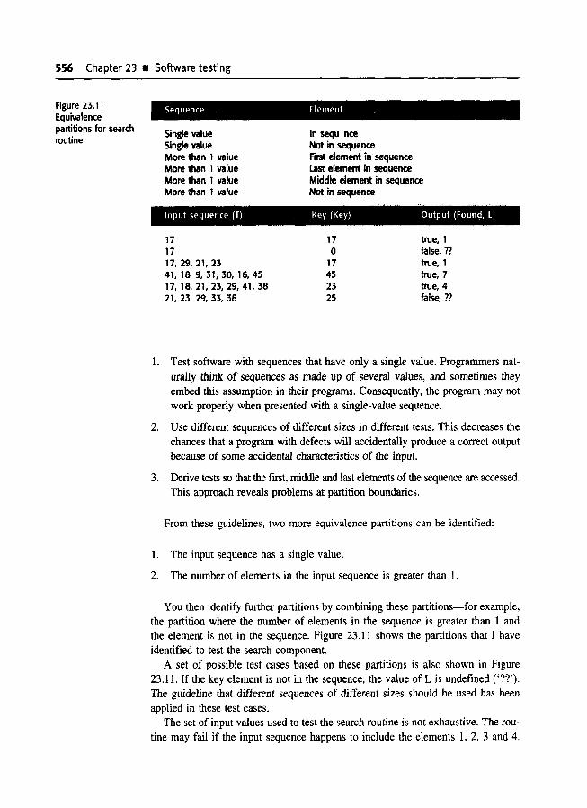
556 Chapter 23 • Software testing
Sequence ElementFigure 23.11Equivalencepartitions for searchroutine
Single valueSingle valueMore than 1 valueMore than 1 valueMore than 1 valueMore than 1 value
In sequ nceNot in sequenceFirst element in sequenceLast element in sequenceMiddle element in sequenceNot in sequence
Input sequence (T) Key (Key) Output (Found, l)
171717,29,21,2341, 18,9,31,30, 16,4517, 18,21,23,29,41,3821, 23, 29, 33, 38
17o
17452325
true, 1false, ntrue, 1true, 7true, 4false, n
1. Test software with sequences that have only a single value. Programmers naturally think of sequences as made up of several values, and sometimes theyembed this assumption in their programs. Consequently, the program may notwork properly when presented with a single-value sequence.
2. Use different sequences of different sizes in different tests. This decreases thechances that a program with defects will accidentally produce a correct outputbecause of some accidental characteristics of the input.
3. Derive tests so that the fIrst, middle and last elements of the sequence are accessed.This approach reveals problems at partition boundaries.
From these guidelines, two more equivalence partitions can be identified:
1. The input sequence has a single value.
2. The number of elements in the input sequence is greater than 1.
You then identify further partitions by combining these partitions-for example,the partition where the number of elements in the sequence is greater than 1 andthe element is not in the sequence. Figure 23.11 shows the partitions that I haveidentifIed to test the search component.
A set of possible test cases based on these partitions is also shown in Figure23.11. If the key element is not in the sequence, the value of L is undefIned ('n').The guideline that different sequences of different sizes should be used has beenapplied in these test cases.
The set of input values used to test the search routine is not exhaustive. The routine may fail if the input sequence happens to include the elements 1, 2, 3 and 4.

233 • Test case design 557-------_.__._--------
19ll!sts Derives
l Testoutputs
Elements> Mid
However, it is reasonable to assume that if the test fails to detect defects when onemember of a class is processed, no other members of that class will identify defects.Of COurSE, defects may still exist. Some equivalence partitions may not have beenidentified, errors may have been made in equivalence partition identification or thetest data may have been incorrectly prepared.
StructUi~al testi.....;ng=-- _
Structural testing (Figure 23.12) is an approach to test case design where the testsare derived from knowledge of the software's structure and implementation. Thisapproach is sometimes called 'white-box', 'glass-box' testing, or "clear-box' testing to di,tinguish it from black-box testing.
Understanding the algorithm used in a component can help you identify furtherpartitions and test cases. To illustrate this, I have implemented the search routinespecification (Figure 23.10) as a binary search routine (Figure 23.14). Of course,this has stricter prt~-conditions. The sequence is implemented as an array that arraymust be ordered and the value of the lower bound of the array must be less thanthe value of the upper bound.
By examining the code of the search routine, you can see that binary searchinginvolves splitting the search space into three parts. Each of these parts makes upan equivalence partition (Figure 23.13). You then design test cases where the keylies at the boundaJies of each of these partitions.
Equivalence class boundaries
tEl,,,,,""<"dMid-point

558 Chapter 23 i: Software testing
Figure 23.14 Javaimplementation of abinary search routine
class BinSearch {
II This is an encapsulation of a binary search function that takes an array ofII ordered objects and a key and returns an object with 2 attributes namelyII index - the value of the array indexII found - a boolean indicating whether or not the key is in the arrayII An object is returned because it is not possible in Java to pass basic typesbyII reference to a function and so return two valuesI I the key is -1 if the element is not found
public static void search ( int key, int 0 elemArray, Result r ){
1. int bottom =0 ;2. int top = elemArray.length - 1 ;
int mid;3. r.found = false ;4. r.index = -1 ;5. while ( bottom <= top )
{6 mid = (top + bottom) I 2 ;7 if (elemArray [mid] = key)
{8 rindex = mid;9 r.found = true ;10 return ;
} II if partelse{
11 if (elemArray [mid] < key)12 bottom = mid + 1 ;
else13 top = mid - 1 ;
}} Ilwhile loop
14. } II search} IIBinSearch
This leads to a revised set of test cases for the search routine, as shown in Figure23.15. Notice that I have modified the input array so that it is arranged in ascending order and have added further tests where the key element is adjacent to the midpoint of the array.

23 3 'il Test case design 559
Input array (T) Key (Key) Output (Found, l)Figure 23.15 Testcases for searchroutine 17
1717, 21. 23, 2'~
9, 16, 18,30,31,41,4517, 1~I., 21, 2:S, 29, 38, 4117, 1~1" 21, 2:5, 29, 33, 3812, IS", 21, 2:5, 3221, 2:l, 29, 3:5, 38
17o
174523212325
true, 1false, ??true, 1true, 7true, 4true, 3true, 4false, n
23.3.4 Path t~:sting:
Path testmg is a structural testing strategy whose objective is to exercise every independent 1,:xecutIon path through a component or program. If every independent pathis executed, then all statements in the component must have been executed at least
once. Furthermore, all conditional statements are tested for both true and false cases.In an ob~!ect-orjented development process, path testing may be used when testing
methods associated with objects.
The number of paths through a program is usually proportional to its size. As mod
ules are integrated into systems, it becomes unfeasible to use structural testing techniques. Path tesl~ng techniques are therefore mostly used during component testing.
Path testing does not test all possible combinations of all paths through the program. For any components apart from very trivial ones without loops, this is an
impossible objective. There are an infinite number of possible path combinationsin programs wilth loops. Even when all program statements have been executed at
least once, program defects may still show up when particular paths are combined.
The starting point for path testing is a program flow graph. This is a skeletalmodel of all paths through the program. A flow graph consists of nodes representing deciSIOns and edges showing flow of control. The flow graph is constructed by
replacing program control statements by equivalent diagrams. If there are no gotostatements in a program, it is a simple process to derive its flow graph. Each branchin a conditional statement (if-then-else or case) is shown as a separate path. An arrowlooping back to the condition node denotes a loop. I have drawn the flow graph forthe binary search method in Figure 23.16. To make the correspondence betweenthis and the program in Figure 23.14 more obvious, I have shown each statement
as a separate node where the node number corresponds to the line number in theprogram,
The objective of path testing is to ensure that each independent path through theprogram LS executed at least once. An independent program path is one that traverses at least one new edge in the flow graph. In program terms, this means exercising one or more new conditions. Both the true and false branches of allcondition:; must be executed.
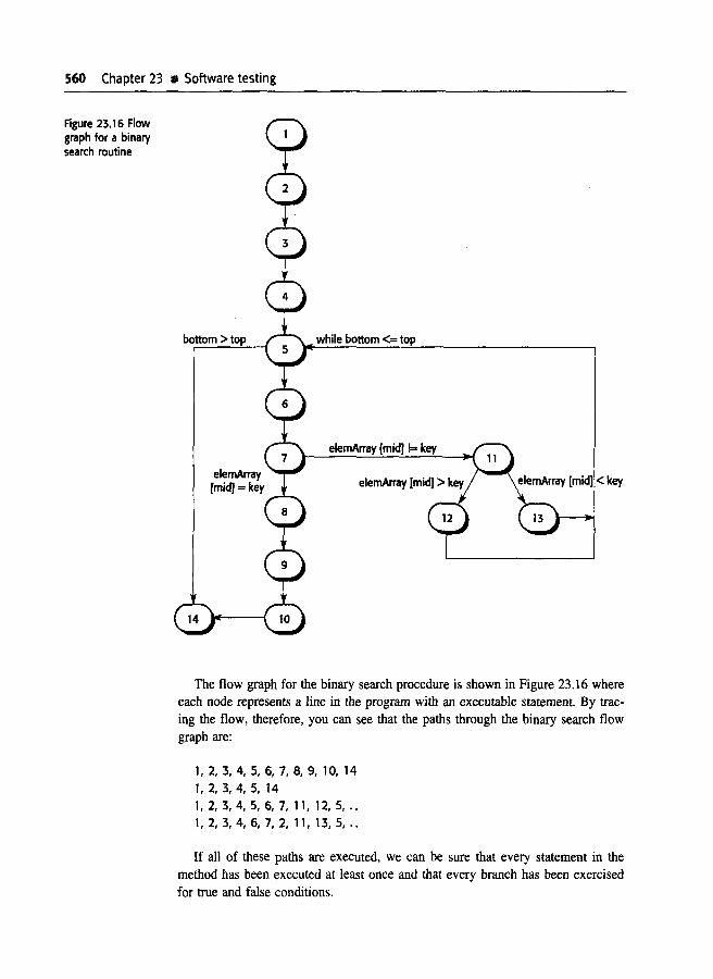
560 Chapter 23 \I Software testing
Figure 23.16 Flowgraph for a binarysearch routine
bottom >top while bottom <= top
elemArray [mid] != key
The flow graph for the binary search procedure is shown in Figure 23.16 whereeach node represents a line in the program with an executable statement. By tracing the flow, therefore, you can see that the paths through the binary search flowgraph are:
1,2,3,4,5,6,7,8,9, 10, 14I, 2, 3, 4, 5, 141,2,3,4,5,6,7, 11, 12,5, ..1,2,3,4,6,7,2,11,13,5, ..
If all of these paths are executed, we can be sure that every statement in themethod has been executed at least once and that every branch has been exercisedfor true and false conditions.

23.4 iii Test automation 561
You can find the number of independent paths in a program by computing thecyclomatic complexity (McCabe, 1976) of the program flow graph. For programs
without goto statements, the value of the cyclomatic complexity is one more than
the number of conditions in the program. A simple condition is logical expression
without 'and' or 'or connectors. If the program includes compound conditions, which
are logical expressions including 'and' or 'or' connectors, then you count the number of simple conditions in the compound conditions when calculating the cyclo
matic complexity.Therefore, if there are six if-statements and a while loop and all conditional expres
sions are simple, the cyclomatic complexity is 8. If one conditional expression is a
compound expression such as 'if A and B or C', then you count this as three simple condItions. The cyclomatic complexity is therefore 10. The cyclomatic complexity
of the blllary search algorithm (Figure 23.14) is 4 because there are three simple
conditions at lines 5, 7 and 11.
After discovering the number of independent paths through the code by computing tbe cyclomatic complexity, you next design test cases to execute each of thesepaths. The minimum number of test cases that you need to test all program paths
is equal to the cyc10matic complexity.Test case design is straightforward in the case of the binary search routine. However,
when programs have a complex branching structure, it may be difficult to predicthow an) partic:ular test case will be processed. In these cases, a dynamic programanalyser can be used to discover the program s execution profile.
Dynamic program analysers are testing tools that work in conjunction with compilers. During compilation, these analysers add extra instructions to the generated
code. These count the number of times each program statement has been executed.
After the program has been run, an execution profile can be printed. This shows
which parts of the program have and have not been executed using particular testcases. This execution profile therefore reveals untested program sections.
23.4 Test clutomation
Testing is an expensive and laborious phase of the software process. As a result,
testing tools were among the first software tools to be developed. These tools now
offer a rouge of facilities and their use can significantly reduce the costs of testing.I have already discussed one approach to test automation (Mosley and Posey,
2002) where a testing framework such as JUnit (Massol and Husted, 2003) is usedfor regre;sion testing. JUnit is a set of Java classes that the user extends to createan automated testing environment. Each individual test is implemented as anobject and a test runner runs all of the tests. The tests themselves should be written in such a way that they indicate whether the tested system has behaved as expected.

Software testing
A software testing workbench is an integrated set of tools to support the testingprocess. In addition to testing frameworks that support automated test execution, aworkbench may include tools to simulate other parts of the system and to generatesystem test data. Figure 23.17 shows some of the tools that might be included insuch a testing workbench:
1. Test manager Manages the running of program tests. The test manager keepstrack of test data, expected results and program facilities tested. Test automation frameworks such as JUnit are examples of test managers.
2. Test data generator Generates test data for the program to be tested. This maybe accomplished by selecting data from a database or by using patterns to generate random data of the correct form.
3. Oracle Generates predictions of expected test results. Oracles may either beprevious program versions or prototype systems. Back-ta-back testing (discussedin Chapter 17) involves running the oracle and the program to be tested in parallel. Differences in their outputs are highlighted.
4. File comparator Compares the results of program tests with previous test resultsand reports differences between them. Comparators are used in regression testing where the results of executing different versions are compared. Where automated tests are used, this may be called from within the tests themselves.
5. Report generator Provides report definition and generation facilities for test results.

Chapter 23 Key Points 563
6. Dynamic analyser Adds code to a program to count the number of times eachstatement has been executed. After testing, an execution profile is generatedshowing how often each program statement has been executed.
7. Simulator Different kinds of simulators may be provided. Target simulators simulate the machine on which the program is to execute. User interface simulaton are script-driven programs that simulate multiple simultaneous userinteTactions. Using simulators for I/O means that the timing of transactionsequences is repeatable.
When used for large system testing, tools have to be configured and adapted forthe spedfic system that is being tested. For example:
IIKEY POINTS
1111II11>Testing can only show the presence of errors in a program. It cannot demonstrate that thereare no remaining faults.
Component testing is the responsibility of the component developer. A separate testingteam usually carries out sy5item testing.
Integration testing is the initial system testing activity where you test integratedcomponents for defec:ts. Rellease testing is concerned with testing customer releases andshould validate that the system to be released meets its requirements.
When testing systems, you should try to 'break' the system by using experience andguidelines to choose types of test cases that have been effective in discovering defects inother systems.
Interface testing is intended to discover defects in the interfaces of composite components.Interface defects mal' arise because of errors made in reading the specification,specification mjsundf~rstandings or errors or invalid timing assumptions.
Equivalence partitioning is ia way of deriving test cases. It depends on finding partitions inthe input and output data sets and exercising the program with values from thesepartitions. Often, the value that is most likely to lead to a successful test is a value at theboundary of a partitkm.
Structural testing relies on analysing a program to determine paths through it and usingthis analysis to assist with the selection of test cases.
Test automation reduces the costs of testing by supporting the testing process with a rangeof software tools.
564 Chapter 23 Software testing
1. New tools may have to be added to test specific application characteristics, andsome existing testing tools may not be required.
2. Scripts may have to be written for user interface simulators and patternsdefined for test data generators. Report formats may also have to be defined.
3. Sets of expected test results may have to be prepared manually if no previousprogram versions are available to serve as an oracle.
4. Special-purpose file comparators may have to be written that include knowledge of the structure of the test results on file.
A significant amount of effort and time is usually needed to create a comprehensive testing workbench. Complete test workbenches, as shown in Figure 23.17,are therefore only used when large systems are being developed. For these systems,the overall testing costs may be up to 50% of the total development costs so it iscost-effective to invest on high-quality CASE tool support for testing. However,because different types of systems require different types of testing support, offthe-shelf testing tools may not be available. Rankin (Rankin, 2002) discusses sucha situation in IBM and describes the design of the testing support system that theydeveloped for an e-business server.
FURTHER READING i: _
How to Break Software: A Practical Guide to Testing. This is a practical rather than theoretical bookon software testing where the author presents a set of experience-based guidelines on designingtests that are likely to be effective in discovering system faults. (J. A. Whittaker, 2002, AddisonWesley.)
'Software Testing and Verification', This special issue of the IBM Systems Journal includes anumber of papers on testing, including a good overview, papers on test metrics and testautomation. (IBM Systems Journal, 41(1), January 2002,)
Testing Object-oriented Systems: Models, Patterns and Tools. This immense book providescomplete coverage of object-oriented testing. Its length means that this shouldn't be the first thingthat you read on object-oriented testing (most books on object-oriented development have atesting chapter) but it is clearly the definitive book on object-oriented testing. (R. V. Binder, 1999,Addison-Wesley.)
'How to design practical test cases'. A how-to article on test case design by an author from aJapanese company that has a very good reputation for delivering software with very few faults.(T, Yamaura, IEEE Software, 15(6), November 1998.)

Chapter 23 III Exercises 565---------.._-,----------
EXERCISES
23.1 Explain why testin1: can only detect the presence of errors, not their absence.
23.2 Compare top-down and bottom-up integration and testing by discussing their advantages anddisadvantages for architectural testing, demonstrating a version of the system to users andfor the practical implementation and observation of tests. Explain why most large systemintegration, in practice, has to use a mixture of top-down and bottom-up approaches.
23.3 What is regression testing? Explain how the use of automated tests and a testing frameworksuch as JUnit simplifies regression testing.
23.4 Write a scenario that could be used as the basis for deriving tests for the weather stationsystem that was used as an example in Chapter 14.
23.5 Using the sequence diagram in Figure 8.14 as a scenario, propose tests for the issue ofelectronic items in the L1BSYS system.
23.6 What are the problems in developing performance tests for a distributed database systemsuch as the L1BSYS system?
23.7 Explain why interface testing is necessary even when individual components have beenextensively validated through component testing and program inspections.
23.8 Using the approach discussed here for object testing, design test cases to test the states ofthe microwave oven whose state model is defined in Figure 8.5.
23.9 You have been asked to te'st a method called catWhiteSpace in a Paragraph object that, withinthe paragraph, replaces se!quences of blank characters with a single blank character. Identifytesting partitions for this E!xample and derive a set of tests for the catWhiteSpace method.
23.10 Give three situations wher,e the testing of all independent paths through a program may notdetect program errors.

24Critical systemsvalidation
ObjectivesThe objective of this chapter is to discuss verification and validationtechniques that are used in the development of critical systems.When you have read this chapter, you will:
• understand how the reliability of a software system can bemeasured and how reliability growth models can be used topredict when a required level of reliability will be achieved;
• understand the principles of safety arguments and how thesemay be used along with other V & V methods in system safetyassurance;
• understand the problems of assuring the security of a system;
• have been introduced to safety cases that present argumentsand evidence of system safety.
Contents24.1 Reliability validation
24.2 Safety assurance
24.3 Security assessment24.4 Safety and dependability cases
Chapter 24 ~I Critical systems validation 567--------_..__.__._-------
The verification and validation of a critical system has, obviously, much in com
mon with the validation of any other system. The V & V processes should demonstrate that the system meets its specification, and that the system services and behaviour
support the customer s requirements. However, for critical systems, where a high
level of dependability is required, additional testing and analysis are required to produce evidence that the system is trustworthy. There are two reasons why you should
do this:
1. COltS offailure The costs and consequences of critical systems failure are potentially much greater than for noncritical systems. You lower the risks of system
failure by spending more on system verification and validation. It is usually
cheaper to find and remove faults before the system is delivered than to payfor the consequent costs of accidents or disruptions to system service.
2. Validation of dependability attributes You may have to make a formal case to
customers that the system meets its specified dependability requirements(availabililty, reliability, safety and security). Assessing these dependability
characteristics requires specific V & V activities discussed later in this chapter. In some cases, external regulators such as national aviation authorities may
have to certify that the system is safe before it can be deployed. To obtain thiscertification, you may have to design and carry out special V & V procedures
that collect evidence about the system's dependability.
For trlese reasons, the costs of V & V for critical systems are usually much higherthan for other (:lasses of system. It is normal for V & V to take up more than 50%
of the total development costs for critical software systems. This cost is, of course,justified, if an expensive system failure is avoided. For example, in 1996 a mission
critical software system on the Ariane 5 rocket failed and several satellites weredestroyed. The losses were in the hundreds of millions of dollars. The subsequent
enquiry discovered that deficiencies in system V & V were partly responsible for
this fail ureoAlthOllgh the critical systems validation process mostly focuses on validating the
system, related activities should verify that defined system development processeshave been followed. As I discuss in Chapters 27 and 28, system quality is affectedby the qllality of processes used to develop the system. In short, good processeslead to good systems. Therefore, to produce dependable systems, you need to be
confident that a sound development process has been followed.This process assurance is an inherent part of the ISO 9000 standards for quality
management, discussed briefly in Chapter 27. These standards require documenta
tion of the processes that are used and associated activities that ensure that theseprocesses have been followed. This normally requires the generation of process records,such as Signed forms, that certify the completion of process activities and productquality checks. ISO 9000 standards specify what tangible process outputs shouldbe produced and who is responsible for producing them. In Section 24.2.2, I givean example of a process record for a hazard analysis process.

568 Chapter 24 ". Critical systems validation
Figure 24.1 Thereliabilitymeasurementprocess
24.1 Reliability validation
As I explained in Chapter 9, a number of metrics have been developed to specifya system's reliability requirements. To validate that the system meets these requirements, you have to measure the reliability of the system as seen by a typical system user.
The process of measuring the reliability of a system is illustrated in Figure 24.1.This process involves four stages:
1. You start by studying existing systems of the same type to establish an operational profile. An operational profile identifies classes of system inputs andthe probability that these inputs will occur in normal use.
2. You then construct a set of test data that reflect the operational profile. Thismeans that you create test data with the same probability distribution as thetest data for the systems that you have studied. Normally, you use a test datagenerator to support this process.
3. You test the system using these data and the count the number and type of failures that occur. The times of these failures are also logged. As discussed inChapter 9, the time units that you choose should be appropriate for the reliability metric used.
4. After you have observed a statistically significant number of failures, you cancompute the software reliability and work out the appropriate reliability metric value.
This approach is sometimes called statistical testing. The aim of statistical testing is to assess system reliability. This contrasts with defect testing, discussed inChapter 23, where the aim is to discover system faults. Prowell et al. (Prowell, etal., 1999) give a good description of statistical testing in their book on Cleanroomsoftware engineering.
This conceptually attractive approach to reliability measurement is not easy toapply in practice. The principal difficulties that arise are due to:

24.1 Reliability validation 569---------,.._-,------------------------
1. Operational profile uncertainty The operational profiles based on experiencewith other systems may not be an accurate reflection of the real use of the system.
2. High costs of test data generation It can be very expensive to generate the largevolume of data required in an operational profile unless the process can be totallyautomated.
3. Statistical uncertainty when high reliability is specified You have to generatea statistically significant number of failures to allow accurate reliability measurements. When the software is already reliable, relatively few failures occurand it is dinicult to generate new failures.
Devdoping an accurate operational profile is certainly possible for some typesof systems, such as telecommunication systems, that have a standardised pattern ofuse. FOI other system types, however, there are many different users who each havetheir own ways of using the system. As I discussed in Chapter 3, different userscan get quite different impressions of reliability because they use the system in different ways.
By far the best way to generate the large data set required for reliability measurement is to use a test data generator that can be set up to automatically generate inputsmatching the operational profile. However, it is not usually possible to automate theproduction of aJ.l test data for interactive systems because the inputs are often a responseto system outputs. Data sets for these systems have to be generated manually, withcorrespondingly higher costs. Even where complete automation is possible, writing commands tor the test data generator may take a significant amount of time.
Statistical uncertainty is a general problem in measuring the reliability of a system. To make an accurate prediction of reliability, you need to do more than simply cause a single system failure. You have to generate a reasonably large,statistically significant number of failures to be confident that your reliability measurement is accurate. The better you get at minimising the number of faults in asystem. the harder it becomes to measure the effectiveness of fault minimisationtechniques. If very high levels of reliability are specified, it is often impractical togenerate enough system failures to check these specifications.
24.1.1 Oper~tional p_ro_f_il_e_s _
The operational profile of the software reflects how it will be used in practice. Itconsist:; of a specification of classes of input and the probability of their occurrence.When a new software system replaces an existing manual or automated system, itis reasonably easy to assess the probable pattern of usage of the new software. Itshould correspond to the existing usage, with some allowance made for the newfunctionality that is (presumably) included in the new software. For example, anoperational profile can be specified for telecommunication switching systemsbecause telecorrununication companies know the call patterns that these systems haveto handle.
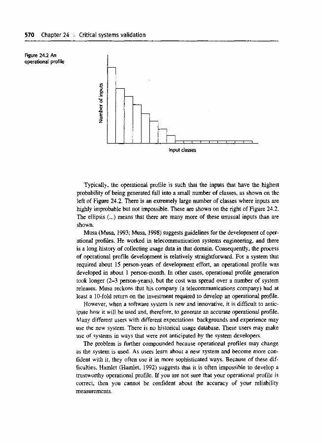
570 Chapter 24 Critical systems validation
Figure 24.2 Anoperational profile
~~
0..5'0
.8E~z
-f--
-
Input classes
Typically, the operational profile is such that the inputs that have the highestprobability of being generated fall into a small number of classes, as shown on theleft of Figure 24.2. There is an extremely large number of classes where inputs arehighly improbable but not impossible. These are shown on the right of Figure 24.2.The ellipsis (...) means that there are many more of these unusual inputs than areshown.
Musa (Musa, 1993; Musa, 1998) suggests guidelines for the development of operational profiles. He worked in telecommunication systems engineering, and thereis a long history of collecting usage data in that domain. Consequently, the processof operational profile development is relatively straightforward. For a system thatrequired about 15 person-years of development effort, an operational profile wasdeveloped in about 1 person-month. In other cases, operational profile generationtook longer (2-3 person-years), but the cost was spread over a number of systemreleases. Musa reckons that his company (a telecommunications company) had atleast a lO-fold return on the investment required to develop an operational profile.
However, when a software system is new and innovative, it is difficult to anticipate how it will be used and, therefore, to generate an accurate operational profile.Many different users with different expectations backgrounds and experience mayuse the new system. There is no historical usage database. These users may makeuse of systems in ways that were not anticipated by the system developers.
The problem is further compounded because operational profiles may changeas the system is used. As users learn about a new system and become more confident with it, they often use it in more sophisticated ways. Because of these difficulties, Hamlet (Hamlet, 1992) suggests that it is often impossible to develop atrustworthy operational profile. If you are not sure that your operational profile iscorrect, then you cannot be confident about the accuracy of your reliabilitymeasurements.

24 1 a Reliability validation 571
t5
L---,G:0u0Cl:.....
~:.c.!SIii,t::
'-'tl t2 t3 t4
Time
Figure 24.3 Equalstep function modelof reliability growth
24.1.2 Reliabili.ty pn~d,i_c_ti_on _
During software validation, managers have to assign effort to system testing. Astesting is very expensive, it is important to stop testing as soon as possible and notover-test' the system. Testing can stop when the required level of system reliabil
ity has be,~n achlleved. Sometimes, of course, reliability predictions may reveal thatthe required level of reliability will never be achieved. In this case, the managermust make difficult decisions about rewriting parts of the software or renegotiatingthe system contract..
A reliability growth model is a model of how the system reliability changes overtime during the testing process. As system failures are discovered, the underlyingfaults causing these failures are repaired so that the reliability of the system shouldimprove during system testing and debugging. To predict reliability, the conceptualreliability growth model must then be translated into a mathematical model. I donot go into this level of detail here but simply discuss the principle of reliabilitygrowth.
There are various reliability growth models that have been derived from reliability experiments in a number of different application domains. As Kan (Kan, 2(03)discusses, most of these models are exponential, with reliability increasing quicklyas defects are discovered and removed (see Figure 24.5). The increase then tails offand reaches a plateau as fewer and fewer defects are discovered and removed inthe later,tages of testing.
The sHnplest model that illustrates the concept of reliability growth is a step function model (Jelinski and Maranda, 1972). The reliability increases by a constantincrement each time a fault (or a set of faults) is discovered and repaired (Figure24.3) and a new version of the software is created. This model assumes that soft-

S72 Chapter 24 If Critical systems validation
Figure 24.4 Randomstep function modelof reliability growth
Note different reliability
/jimprovements Fault repair adds new fault
./ and decreases reliability./ (increases ROCOF)
r-------,
tl t2 t3Time
t4 t5
ware repairs are always correctly implemented so that the number of software faultsand associated failures decreases in each new version of the system. As repairs aremade, the rate of occurrence of software failures (ROCOF) should thereforedecrease, as shown in Figure 24.3. Note that the time periods on the horizontal axisreflect the time between releases of the system for testing so they are normally ofunequal length.
In practice, however, software faults are not always fixed during debugging, andwhen you change a program, you sometimes introduce new faults into it. The probability of occurrence of these faults may be higher than the occurrence probabilityof the fault that has been repaired. Therefore, the system reliability may sometimesworsen in a new release rather than improve.
The simple equal-step reliability growth model also assumes that all faults contribute equally to reliability and that each fault repair contributes the same amountof reliability growth. However, not all faults are equally probable. Repairing themost common faults contributes more to reliability growth than does repairing faultsthat occur only occasionally. You are also likely to find these probable faults earlyin the testing process, so reliability may increase more than when later, less probable, faults are discovered.
Later models, such as that suggested by Littlewood and Verrall (Littlewood andVerrall, 1973) take these problems into account by introducing a random elementinto the reliability growth improvement effected by a software repair. Thus, eachrepair does not result in an equal amount of reliability improvement but varies depending on the random perturbation (Figure 24.4).
Littlewood and Verrall's model allows for negative reliability growth when a software repair introduces further errors. It also models the fact that as faults are repaired,the average improvement in reliability per repair decreases. The reason for this isthat the most probable faults are likely to be discovered early in the testing process. Repairing these contributes most to reliability growth.

24.1 • Reliability validation 573
Requiredreliability
•• =Measured reliability
Fitted reliabilitymodel curve
Estimated Timetime of reliability
achievement
The above models are discrete models that reflect incremental reliability growth.When a new version of the software with repaired faults is delivered for testing, itshould have a lower rate of failure occurrence than the previous version. However,to predict the rebability that wiII be achieved after a given amount of testing, continuous mathema1ical models are needed. Many models, derived from different application domains, have been proposed and compared (Littlewood, 1990).
Simplistically" you can predict reliability by matching the measured reliabilitydata to a known reliability model. You then extrapolate the model to the requiredlevel of reLiability and observe when the required level of reliability will be reached(Figure 24,5). lllerefore, testing and debugging must continue until that time.
Predicting system reliability from a reliability growth model has two mainbenefits:
I. Plannmg of testing Given the current testing schedule, you can predict whentesting will be completed. If this is after the planned delivery date for the sys
tem, then you may have to deploy additional resources for testing and debugging to accelerate the rate of reliability growth.
2. Customer negotiations Sometimes the reliability model shows that the growth ofreliability is very slow and that a disproportionate amount of testing effort is requiredfor reLatively little benefit. It may be worth renegotiating the reliability requirements with tile customer. Alternatively, it may be that the model predicts that therequired reliability will probably never be reached. In this case, you will have torenegotiate tile reliability requirements with the customer for the system.
574 Chapter 24 II Critical systems validation
I have simplified reliability growth modelling here to give you a basic understanding of the concept. If you wish to use these models, you have to go into muchmore depth and develop an understanding of the mathematics underlying these models and their practical problems. Littlewood and Musa (Littlewood, 1990; AbdelGhaly, et al., 1986; Musa, 1998) have written extensively on reliability growth modelsand Kan (Kan, 2003) has an excellent summary in his book. Various authors havedescribed their practical experience of the use of reliability growth models (Ehrlich,et al., 1993; Schneidewind and Keller, 1992; Sheldon, et al., 1992).
24.2 Safety assurance
The processes of safety assurance and reliability validation have different objectives. You can specify reliability quantitatively using some metric and then measure the reliability of the completed system. Within the limits of the measurementprocess, you know whether the required level of reliability has been achieved. Safety,however, cannot be meaningfully specified in a quantitative way and so cannot bemeasured when a system is tested.
Safety assurance is therefore concerned with establishing a confidence level inthe system that might vary from very low' to 'very high'. This is a matter for professional judgement based on a body of evidence about the system, its environmentand its development processes. In many cases, this confidence is partly based onthe experience of the organisation developing the system. If a company has previ'ously developed a number of control systems that have operated safely, then it isreasonable to assume that they will continue to develop safe systems of this type.
However, such an assessment must be backed up by tangible evidence from thesystem design, the results of system V& V, and the system development processesthat have been used. For some systems, this tangible evidence is assembled in asafety case (see Section 24.4) that allows an external regulator to come to a conclusion of the developer s confidence in the system's safety is justified.
The V & V processes for safety-critical systems have much in common with thecomparable processes of any other systems with high reliability requirements.There must be extensive testing to discover as many defects as possible, and whereappropriate, statistical testing may be used to assess the system reliability.However, because of the ultra-low failure rates required in many safety-critical systems, statistical testing cannot always provide a quantitative estimate of the systemreliability. The tests simply provide some evidence, which is used with other evidence such as the results of reviews and static checking (see Chapter 22), to makea judgement about the system safety.
Extensive reviews are essential during a safety-oriented development process toexpose the software to people who will look at it from different perspectives. Parnas

24 2 • Safety assurance 575
et al. (Pamas, et al., 1990) suggest five types of review that should be mandatoryfor safl:ty-critical systems:
1. review for correct intended function;
2. review for maintainable, understandable structure;
3. review to verify that the algorithm and data structure design are consistent withtht: specified behaviour;
4. review the consistency of the code and the algorithm and data structure design;
5. reView the adequacy of the system test cases.
An assumption that underlies work in system safety is that the number of system faults that can lead to safety-critical hazards is significantly less than the totalnumbe:r of faults that may exist in the system. Safety assurance can concentrate onthese fimlts with hazard potential. If it can be demonstrated that these faults cannotoccur or, if they do, the associated hazard will not result in an accident, then thesystem is safe. This is the basis of safety arguments that I discuss in the next section.
24.2.1 Safety argum_e_n_ts ,
Proofs of program correctness, as discussed in Chapter 22, have been proposed asa software ve:rification technique for more than 30 years. Formal program proofscan celtainly be constructed for small systems. However, the practical difficultiesof proving that a system meets its specifications are so great that few organisationsconsidc:r correctness proofs to be a cost. Nevertheless, for some critical applications,it may be economical to develop correctness proofs to increase confidence that thesystem meets its safety or security requirements. This is particularly the case wheresafety-~ritical functionality can be isolated in a fairly small sub-system that can beformal:! y specified.
Although it may not be cost-effective to develop correctness proofs for most systems, iJ: is sometimes possible to develop simpler safety arguments that demonstratethat the: program meets its safety obligations. In a safety argument, it is not necesary to prove that the program's functionality is as specified. It is only necessary
to demonstrate that program execution cannot result in an unsafe state.The most effective technique for demonstrating the safety of a system is proof
by contradiction. You start by assuming that an unsafe state, which was identifiedby the system hazard analysis, can be reached by executing the program. You writea predicate that defines this unsafe state. You then systematically analyse the codeand show that, for all program paths leading to that state, the terminating conditionof these paths contradicts the unsafe state predicate. If this is the case, the initialassumption of an unsafe state is incorrect. If you then repeat this for all identifiedhazard;, then the software is safe.
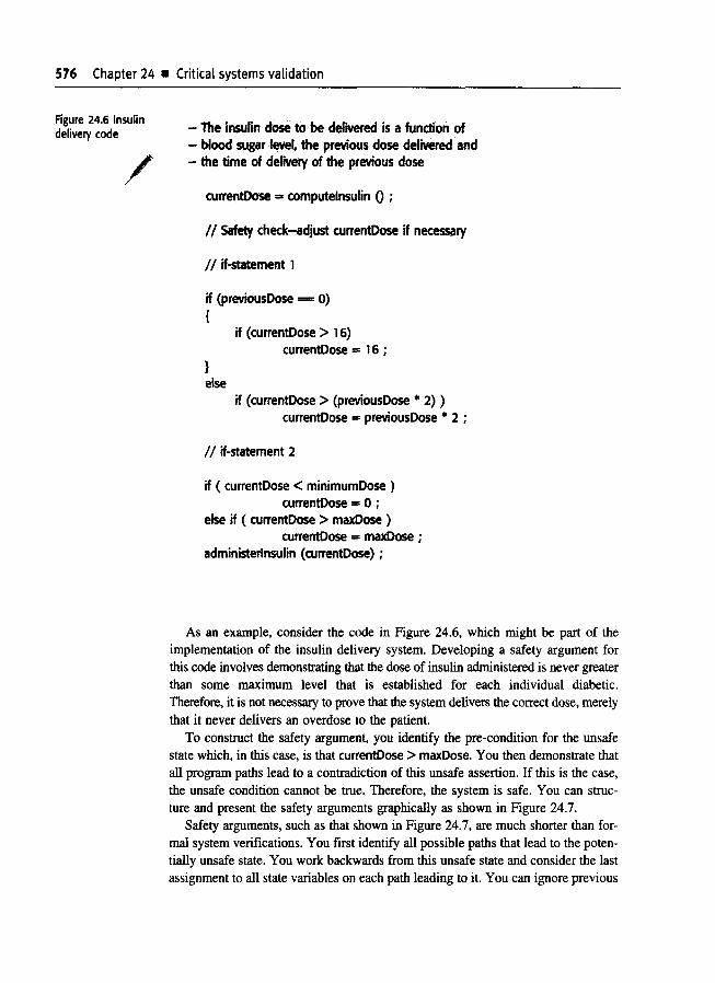
576 Chapter 24 • Critical systems validation
Figure 24.6 Insulindelivery code
/- The insulin dose to be defwerecl is a function of- blood sugar Ieve~ the previous dose delivered and- the time of delivery of the previous dose
currentDose .. computelnsulin 0 ;
II Safety check-adjust currentD05e if necessary
II if-statement 1
if (previousOose === 0){
if (currentDose > 16)currentDose == 16 ;
}else
if (currentD05e > (previousDose * 2) )currentDose == previousDose * 2 ;
/ / if-statement 2
if ( currentDose < minimumDose )currentDose == 0 ;
else if ( currentOose > maxDose )currentDose == maxDose ;
administerlnsulin (currentDose) ;
As an example, consider the code in Figure 24.6, which might be part of theimplementation of the insulin delivery system. Developing a safety argument forthis code involves demonstrating that the dose of insulin administered is never greaterthan some maximum level that is established for each individual diabetic.Therefore, it is not necessary to prove that the system delivers the correct dose, merelythat it never delivers an overdose to the patient.
To construct the safety argument, you identify the pre-condition for the unsafestate which, in this case, is that currentDose > maxDose. You then demonstrate thatall program paths lead to a contradiction of this unsafe assertion. If this is the case,the unsafe condition cannot be true. Therefore, the system is safe. You can structure and present the safety arguments graphically as shown in Figure 24.7.
Safety arguments, such as that shown in Figure 24.7, are much shorter than formal system verifications. You first identify all possible paths that lead to the potentially unsafe state. You work backwards from this unsafe state and consider the lastassignment to all state variables on each path leading to it. You can ignore previous

24 2 • Safety assurance 577----------.._--_._---------
Figure 24.7 Informalsafety argumentbased ondemonstratingcontradictions
ContradiCition
( curre~;tDose >= minimumDose and<:urrentDose <= maxDose
. -iI
not eXl!cuted
"1I!
if statement 2then branch
executed
Pre-eonditionfor unsafe state
Contradlcti
if statement 2else branchexecuted
computallDns (such as if-statement I in Figure 24.7) in the safety argument. In thisexample, all you need be concerned with are the set of possible values ofcurrentDo:.e immediately before the administerlnsulin method is executed.
In the :,afety argument shown in Figure 24.7, there are three possible programpaths that lead to the call to the administerlnsulin method. We wish to demonstratethat the amount of insulin delivered never exceeds maxDose. All possible programpaths to administerlnsulin are considered:

578 Chapter 24 .. Critical systems validation
1. Neither branch of if-statement 2 is executed. This can only happen ifcurrentDose is either greater than or equal to minimumDose and less than orequal to maxDose.
2. The then-branch of if-statement 2 is executed. In this case, the assignment setting currentDose to zero is executed. Therefore, its post-condition iscurrentDose =O.
3. The else-if-branch of if-statement 2 is executed; In this case, the assignmentsetting currentDose to maxDose is executed. Therefore, its post-condition iscurrentDose =maxDose.
In all three cases, the post-conditions contradict the unsafe pre-condition that thedose administered is greater than maxDose, so the system is safe.
24.2.2 Process assurance
I have already discussed the importance of assuring the quality of the system development process in the introduction to this chapter. This is important for all criticalsystems but it is particularly important for safety-critical systems. There are tworeasons for this:
1. Accidents are rare events in critical systems and it may be practically impossible to simulate them during the testing of a system. You can't rely on extensive testing to replicate the conditions that can lead to an accident.
2. Safety requirements, as I discussed in Chapter 9, are sometimes 'shall not' requirements that exclude unsafe system behaviour. It is impossible to demonstrateconclusively through testing and other validation activities that these requirements have been met.
The life-cycle model for safety-critical systems development (Chapter 9, Figure9.7) makes it clear that explicit attention should be paid to safety during all stagesof the software process. This means that specific safety assurance activities mustbe included in the process. These include:
1. The creation of a hazard-logging and monitoring system that traces hazards frompreliminary hazard analysis through to testing and system validation.
2. The appointment of project safety engineers who have explicit responsibilityfor the safety aspects of the system.
3. The extensive use of safety reviews throughout the development process.
4. The creation of a safety certification system whereby the safety of critical components is formally certified.
5. The use of a very detailed configuration management system (see Chapter 29),which is used to track all safety-related documentation and keep it in step with

Figure 24.8 Asimplified hazard logpage
/
24 2 • Safety assurance 579
t1aJ:lIrd LoS Pep 4: PIt.... 20.02.2003System: Ins;ulin Pump System File: InsulinPump/safety/HazardLogSafl ty Engmeer: James Brown Log version: 1/3Ider tified Hazard Insulin overdose delivered to patientIder rifled by Jane WilliamsCriticality dass 1Ider rifled isle HighFault tree identified YES Date 24.01.99 Location Hazard Log, Page 5Fau,~ tree creators Jane Williams and Bill SmithFauJ~ tree checked YES Date 28.01.99 Checker James Brown
System safety design reqUIrements
1. The system shall include self-testing software that will test the sensor system, thedock and the insulin delivery system.
2. The self·-checking software shall be executed once per minute.3. In the event of the self-ehecking software discovering a fault in any of the system
c.omponents, an audible waming shall be issued and the pump display shouldindicate the name of the component where the fault has been discovered. Thedelivery of insulin should be suspended.
4. rhe system shall incorporate an override system that allows the system user tomodify the computed dose of insulin that is to be delivered by the system.
5. The amount of override should be limited to be no greater than a pre-set valuethat is s,et when the system is configured by medical staff.
the associated technical documentation. There is little point in having stringentvalidation procedures if a failure of configuration management means that thewrong system is delivered to the customer.
To illustrate safety assurance, I use the hazard analysis process that is an essential pan of safety-critical systems development. Hazard analysis is concerned withidentifying hazards, their probability, and the probability that these hazards will leadto an accident. If the development process includes clear traceability from hazardidentification through to the system itself, then an argument can be made why thesehazards will IIIot result in accidents. This may be supplemented by safety arguments,as discussed in Section 24.2.1. Where external certification is required before a system is used (<e.g., in an aircraft), it is usually a condition of certification that thistraceability can be demonstrated.
The central safety document is the hazard log, where hazards identified duringthe specificatJiOn process are documented and traced. This hazard log is then usedat each stage of the software development process to assess how that developmentstage has taken the hazards into account. A simplified example of a hazard log entryfor the insulin delivery system is shown in Figure 24.8. This form documents theprocess of hazard analysis and shows design requirements that have been generatedduring this process. These design requirements are intended to ensure that the control system C2ill never deliver an insulin overdose to a user of the insulin pump.
Critical systems validation
As shown in Figure 24.8, individuals who have safety responsibilities should beexplicitly identified. Safety-critical systems development projects should always appointa project safety engineer who is not be involved in the system development. Theengineer s responsibility is to ensure that appropriate safety checks have been madeand documented. The system may also require an independent safety assessor to beappointed from an outside organisation, who reports directly to the client on safetymatters.
In some domains, system engineers who have safety responsibilities must be certified. In the UK, this means that they have to have been accepted as a member ofone of the engineering institutes (civil, electrical, mechanical, etc.) and have to bechartered engineers. Inexperienced, poorly qualified engineers may not takresponsibility for safety.
This does not currently apply to software engineers, although there has been extensive discussion on the licensing of software engineers in several states in the UnitedStates (Knight and Leveson, 2002; Bagert, 2002). However, future process standardsfor safety-critical software development may require that project safety engineersshould be formally certified engineers with a defined minimum level of training.
Run-time safety checking
I described defensive programming in Chapter 20, where you add redundant statements to a program to monitor its operation and check for possible system faults.The same technique can be used for the dynamic monitoring of safety-critical systems.Checking code can be added to the system that checks a safety constraint. Itthrows an exception if that constraint is violated. The safety constraints that shouldalways hold at particular points in a program may be expressed as assertions. Assertionsare predicates that describe conditions that must hold before the following statement can be executed. In safety-eritical systems, the assertions should be generatedfrom the safety specification. They are intended to assure safe behaviour rather thanbehaviour that conforms to the specification.
Assertions can be particularly valuable in assuring the safety of communicationsbetween components of the system. For example, in the insulin delivery system,the dose of insulin administered involves generating signals to the insulin pump todeliver a specified number of insulin increments (Figure 24.9). The number of insulinincrements associated with the allowed maximum insulin dose can be pre-computedand included as an assertion in the system.
If there has been an error in the computation of currentDose, which is the statevariable that holds the amount of insulin to be delivered, or if this value has beencorrupted in some way, then this will be trapped at this stage. An excessive doseof insulin will not be delivered, as the check in the method ensures that the pumpwill not deliver more than maxDose.
From the safety assertions that are included as program comments, code to checkthese assertions can be generated. You can see this in Figure 24.9, where the if-statementafter the assert comment checks the assertion. In principle, much of this code
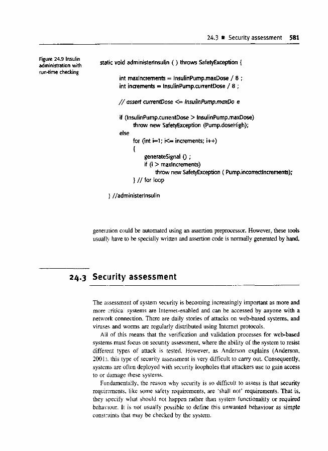
Figure 24.9 Insulinadministration withrun-time checking
24.3 • Security assessment 581
static void administerlnsulin ( ) throws SafetyException {
inlt maxlncrements = InsulinPump.maxDose I 8 ;inlt increments = InsulinPump.currentDose I 8 ;
1/ assert currentDose <= InsulinPump.maxDo e
if (InsulinPump.currentDose > InsulinPump.maxDose)throw new SafetyException (Pump.doseHigh);
for (int i=1; k= increments; i++){
generateSignal 0 ;if (i > maxlncrements)
throw new SafetyException ( Pump.incorrectlncrements);} II for loop
:1 Iladministerinsulin
generation could be automated using an assertion preprocessor. However, these toolsusually have to be specially written and assertion code is normally generated by hand.
24.3 Security assessment
The assessment of system security is becoming increasingly important as more andmore criticall systems are Internet-enabled and can be accessed by anyone with anetwork connection. There are daily stories of attacks on web-based systems, andviruses and worms are regularly distributed using Internet protocols.
All of this means that the verification and validation processes for web-basedsystems must focus on secunty assessment, where the ability of the system to resistdifferent types of attack is tested. However, as Anderson explains (Anderson,2001;. this type of security assessment is very difficult to carry out. Consequently,systems are often deployed with security loopholes that attackers use to gain accessto or damage these systems.
Fundamentally, the reason why security is so difficult to assess is that securityrequir,:ments, like some safety requirements, are 'shall not' requirements. That is.they :;pecify what should not happen rather than system functionality or requiredbeha\'lour. It is not usually possible to define this unwanted behaviour as simpleconstraints (IJat may be checked by the system.
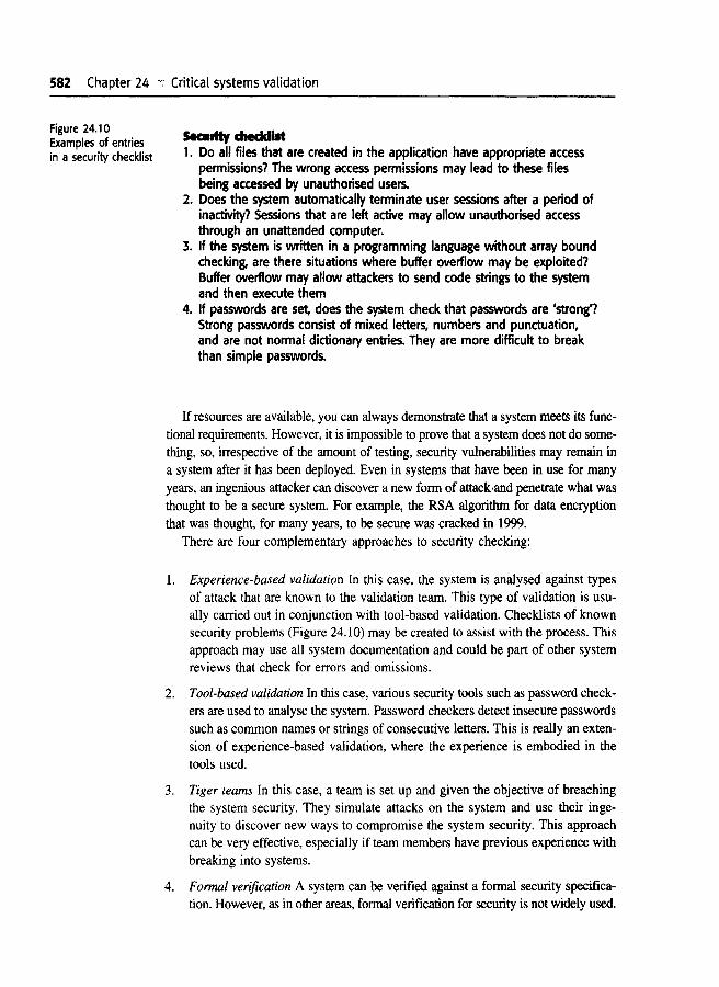
582 Chapter 24 .;- Critical systems validation
Figure 24.10Examples of entriesin a security checklist
5eantty checklist1. Do all files that are created in the application have appropriate access
permissions? The wrong access permissions may lead to these filesbeing accessed by unauthorised users.
2. Does the system automatically terminate user sessions after a period ofinactivity? Sessions that are left active may allow unauthorised accessthrough an unattended computer.
3. If the system is written in a programming language without array boundchecking, are there situations where buffer overflow may be exploited?Buffer overflow may allow attackers to send code strings to the systemand then execute them
4. If passwords are set, does the system check that passwords are 'strong'?Strong passwords consist of mixed letters, numbers and punctuation,and are not normal dictionary entries. They are more difficult to breakthan simple passwords.
If resources are available, you can always demonstrate that a system meets its functional requirements. However, it is impossible to prove that a system does not do something, so, irrespective of the amount of testing, security vulnerabilities may remain ina system after it has been deployed. Even in systems that have been in use for manyyears, an ingenious attacker can discover a new form of attack-and penetrate what wasthought to be a secure system. For example, the RSA algorithm for data encryptionthat was thought, for many years, to be secure was cracked in 1999.
There are four complementary approaches to security checking:
1. Experience-based validation In this case, the system is analysed against typesof attack that are known to the validation team. This type of validation is usually carried out in conjunction with tool-based validation. Checklists of knownsecurity problems (Figure 24.10) may be created to assist with the process. Thisapproach may use all system documentation and could be part of other systemreviews that check for errors and omissions.
2. Tool-based validation In this case, various security tools such as password checkers are used to analyse the system. Password checkers detect insecure passwordssuch as common names or strings of consecutive letters. This is really an extension of experience-based validation, where the experience is embodied in thetools used.
3. Tiger teams In this case, a team is set up and given the objective of breachingthe system security. They simulate attacks on the system and use their ingenuity to discover new ways to compromise the system security. This approachcan be very effective, especially if team members have previous experience withbreaking into systems.
4. Formal verification A system can be verified against a formal security specification. However, as in other areas, formal verification for security is not widely used.
24.4 Safety and dependability cases 583
It is very difficult for end-users of a system to verify its security. Consequently,as discussed by Gollmann (Gollmann, 1999), bodies in North America and in Europehave established sets of security evaluation criteria that can be checked by specialisedevaluators. Software product suppliers can submit their products for evaluation andcertification against these criteria.
Therefore, if you have a requirement for a particular level of security, you can choosea product that has been validated to that level. However, many products are not security-certified or their certification applies only to individual products. When the certified system is used in conjunction with other uncertified systems, such as locally developedsoftware. the security level of the overall system cannot be assessed.
24.4 Safet~' and dependability cases
Safety cases and, more generically, dependability cases are structured documentssetting out detailed arguments and evidence that a system is safe or that a requiredlevel of dl~pendability has been achieved. For many types of critical systems, theproduction of a safety case is a legal requirement, and the case must satisfy somecertification body before the system can be deployed.
Regulators are created by government to ensure that private industry does notprofit by failing to following national standards for safety, security, and so on. Thereare regulators in many different industries. For example, airlines are regulated bynational aviation authorities such as the FAA (in the US) and the CAA (in the UK).Railway regulators exist to ensure the safety of railways, and nuclear regulators mustcertify the safety of a nuclear plant before it can go on line. In the banking sector,national banks serve as regulators, establishing procedures and practices to reducethe probability of fraud and to protect banking customers from risky banking practices. As wftware systems have become increasingly important in the criticalinfrastructure of c:ountries, these regulators have become more and more concernedwith safety and dependability cases for software systems.
The role of a regulator is to check that a completed system is as safe as practicable, so they are mainly involved when a development project is complete.However, regulators and developers rarely work in isolation; they communicate withthe development team to establish what has to be included in the safety case. Theregulator and developers jointly examine processes and procedures to make surethat these ale being enacted and documented to the regulator s satisfaction.
Of course, software itself is not dangerous. It is only when it is embedded in alarge, compllter-based or socio-technical system that software failures can result infailures of other equipment or processes that can cause injury or death. Therefore,a software safety case is always part of a wider system safety case that demonstratesthe safety of the overall system. When constructing a software safety case, you haveto relate software failures to wider system failures and demonstrate that either these

584 Chapter 24 Critical systems validation
Component DescriptionFigure 24.11Components of asoftware safety case System description
Safety requirements
Hazard and riskanalysis
Design analysis
Verification andvalidation
Review reports
Team competences
Process QA
Change managementprocesses
Associated safetycases
An overview of the system and a description of its criticalcomponents
The safety requirements abstracted from the systemrequirements specification
Documents describing the hazards and risks that havebeen identified and the measures taken to reduce risk
A set of structured arguments that justify why the design issafe
A description of the V &V procedures used and, whereappropriate, the test plans for the system
Records of all design and safety reviews
Evidence of the competence of all of the team involved insafety-related systems development and validation
Records of the quality assurance processes carried outduring system development
Records of all changes proposed, actions taken and, whereappropriate, justification of the safety of these changes
References to other safety cases that may impact on thissafety case
software failures will not occur or that they will not be propagated in such a waythat dangerous system failures may occur.
A safety case is a set of documents that include a description of the system, thathas to be certified, information about the processes used to develop the system and,critically, logical arguments that demonstrate that the system is likely to be safe.More succinctly, Bishop and Bloomfield (Bishop and Bloomfield, 1998; Bishop andBloomfield, 1995) define a safety case as:
A documented body of evidence that provides a convincing and valid argumentthat a system is adequately safe for a given application in a given environment.
The organisation and contents of a safety case depends on the type of systemthat is to be certified and its context of operation. Figure 24.11 shows one possibleorganisation for a software safety case.
A key component of a safety case is a set of logical arguments for system safety.These may be absolute arguments (event X will or will not happen) or probabilisticarguments (the probability of event X is G.Y); when combined, these should demonstrate safety. As shown in Figure 24.12, an argument is a relationship between what

24.4 i!l Safety and dependability cases 585--------_..__._---------_._-----------
Figure 24.12 Thestructure of anargument
["DE~« .RGUMENT »--~~-E)
is thoughl to be th~: case (a claim) and a body of evidence that has been collected. Thargument essentially explains why the claim (which is generally that something is safe)can be inferred from the available evidence. Naturally, given the multilevel nature ofsystems. claims are organised in a hierarchy. To demonstrate that a high-level claimis valid, you fIrst have to work through the arguments for lower-level claims. Figure24.13 shows paJt of this claim hierarchy for the insulin pump
As a medical device, the insulin pump system may have to be externally certifIed. For example, in the UK, the Medical DeVIces Directorate have to issue a safetycertifIcate for any medical device that is sold in the UK Various arguments mayhave to be produced to demonstrate the safety of this system. For example, the following argument could be part of a safety case for the insulin pump.
Claim: The maximum single dose computed by the insulin pump willnot exceed maxDose.
Evid,ence: Safety argument for insulin pump (Figure 24.7)
Evid'ence: Test data sets for insulin pump
Evidlmce: Static analysis report for insulin pump software
Argument: The safety argument presented shows that the maximum doseof insulin that can be computed is equal to maxDose.
In 400 tests, the value of Dose was correctly computed and neverexceeded maxDose.
The static analysis of the control software revealed no anomalies.
Overall, it is reasonable to assume that the claim is justified.
Of course, this is a very simplified argument, and in a real safety case detailedreferences to the \~vidence would be presented. Because of their detailed nature, safetycases are therefore very long and complex documents. Various software tools areavailable to help with their construction, and I have included links to these tools inthe book's web pages.
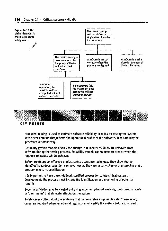
586 Chapter 24 . Critical systems validation
sa safee user ofpump
The insulin pumpwill not deliver asingle dose of insulinthat is unsafe
I - --'---'-~
The maximum singl emaxDose is set up maxDose idose computed by
the pump software correctly when th e dose for thwill not exceed pump is configured the insulinmaxDose ..._._,----
II I
In normal If the software fails,operation, the the maximum dosemaximum dose computed will notcomputed will notexceed maxDose exceed maxDose
/
Figure 24.13 Theclaim hierarchy inthe insulin pumpsafety case
KEY POINTS
Statistical testing is used to estimate software reliability. It relies on testing the systemwith a test data set that. reflects the operational profile of the software. Test data may begenerated automatically.
Reliability growth models display the change in reliability as faults are removed fromsoftware during the testing process. Reliability models can be used to predict when therequired reliability will be achieved.
Safety proofs are an effective product safety assurance technique. They show that anidentified hazardous condition can never occur. They are usually simpler than proving that aprogram meets its specification.
It is important to have a well-defined, certified process for safety-critical systemsdevelopment. The process must include the identification and monitoring of potentialhazards.
Security validation may be carried out using experience-based analysis, tool-based analysis,or 'tiger teams' that simulate attacks on the system.
Safety cases collect all of the evidence that demonstrates a system is safe. These safetycases are required when an external regulator must certify the system before it is used.