TestEquity FOV Series Forced Air Ovens - Installation and ... · FOV Series Forced Air Ovens...
43
Rev, 1.0 – February 17, 2017 FOV Series Forced Air Ovens Installation - Operation Manual TestEquity LLC 6100 Condor Drive Moorpark, CA 93021 Support: 877-512-3457, 805-480-0638 Corporate: 800-732-3457, 805-498-9933 http://www.testequity.com
Transcript of TestEquity FOV Series Forced Air Ovens - Installation and ... · FOV Series Forced Air Ovens...
Rev, 1.0 – February 17, 2017
FOV Series Forced Air Ovens
Installation - Operation Manual
TestEquity LLC 6100 Condor Drive Moorpark, CA 93021 Support: 877-512-3457, 805-480-0638 Corporate: 800-732-3457, 805-498-9933 http://www.testequity.com

2 | P a g e
This page left blank

3 | P a g e
FOV Forced Air Ovens 110 – 120 V Installation and Operation Manual
Revision: February 17, 2017
These units are TÜV CUE listed as forced air ovens for professional, industrial, or educational use where the preparation or testing of materials is done at an ambient air pressure range of 22.14 – 31.3 inHg (75 – 106 kPa) and no flammable, volatile, or combustible materials are being heated.
The units have been tested to the following requirements:
CAN/CSA C22.2 No. 61010-1:2012 CAN/CSA C22.2 No. 61010-2-010:2004 Reaffirmed: 2014-07 UL 61010-1:2012-05 UL 61010A-2-010:2002-03 EN 61010-1:2010 EN 61010-2-010:2014 Supplemented by: UL 61010-2-010:2015

4 | P a g e
TABLE OF CONTENTS INTRODUCTION ..................................................................................................................................................... 5
General Safety Considerations ........................................................................................................................... 5 Engineering Improvements ................................................................................................................................. 6 Contacting Assistance ......................................................................................................................................... 6
RECEIVING YOUR UNIT ........................................................................................................................................ 7
Inspect the Shipment .......................................................................................................................................... 7 Orientation Photos............................................................................................................................................... 8 Record Data Plate Information .......................................................................................................................... 12 Temperature Reference Sensor Device ........................................................................................................... 12
INSTALLATION .................................................................................................................................................... 13
Installation Checklist ......................................................................................................................................... 13 Required Ambient Conditions ........................................................................................................................... 14 Environmental Disruption Sources .................................................................................................................... 14 Power Source Requirements ............................................................................................................................ 15 Lifting and Handling .......................................................................................................................................... 15 Leveling ............................................................................................................................................................. 16 Install the Oven ................................................................................................................................................. 16 Installation Cleaning .......................................................................................................................................... 16 Shelving Installation .......................................................................................................................................... 17 Access Port Stopper ......................................................................................................................................... 17
GRAPHIC SYMBOLS ........................................................................................................................................... 19
CONTROL PANEL OVERVIEW ........................................................................................................................... 21
OPERATION ......................................................................................................................................................... 23
Operating Precautions ...................................................................................................................................... 23 Theory of Operation .......................................................................................................................................... 24 Put the Oven into Operation .............................................................................................................................. 26 Set the Oven Temperature Set Point ................................................................................................................ 27 Set the Over Temperature Limit ........................................................................................................................ 28 Setting the Timer ............................................................................................................................................... 29 Drying Racks and other Accessories ................................................................................................................ 30 Launch a Heating Profile ................................................................................................................................... 31 High Exterior Temperatures .............................................................................................................................. 32
USER MAINTENANCE ......................................................................................................................................... 33
Cleaning and Disinfecting ................................................................................................................................. 33 Calibrate the Temperature Display ................................................................................................................... 34 Door Components and Seal .............................................................................................................................. 38 Electrical Components ...................................................................................................................................... 38
UNIT SPECIFICATIONS ....................................................................................................................................... 39
Weight ............................................................................................................................................................... 39 Dimensions ........................................................................................................................................................ 39 Capacity ............................................................................................................................................................ 39 Shelf Capacity by Weight .................................................................................................................................. 40 Temperature ...................................................................................................................................................... 40 Ventilation Rates ............................................................................................................................................... 41 Power ................................................................................................................................................................ 41
PARTS LIST ......................................................................................................................................................... 42
5 | P a g e
INTRODUCTION
Thank you for purchasing a TestEquity oven. We know you have many choices in today’s competitive marketplace when it comes to constant temperature equipment. We appreciate you choosing ours. We stand behind our products and will be here if you need us.
Locations and Applications Range
These ovens are intended for professional, industrial, and educational applications. The ovens are not intended for use at hazardous or household locations. FOV forced-air ovens are engineered for constant temperature forced-air drying, curing, and baking applications.
User Manual
Before using the unit read this manual in its entirety to understand how to install, operate, and maintain the unit in a safe manner. Keep this manual available for use by all operators. Ensure that all operators are given appropriate training before the unit begins service.
GENERAL SAFETY CONSIDERATIONS Note: Failure to follow the guidelines and instructions in this manual may create a protection
impairment by disabling or interfering with the unit safety features. This can result in injury or death.
Your unit and its recommended accessories are designed and tested to meet strict safety requirements. It is designed to connect to a power source using the specific power cord type shipped with the unit.
For continued safe operation of your unit, always follow basic safety precautions including:
• Always plug the unit power cord into a protective earth grounded electrical outlet that conforms to national and local electrical codes. If the unit is not grounded properly, parts such as knobs and controls can conduct electricity and cause serious injury.
• Do not bend the power cord excessively, step on it, or place heavy objects on it.
• A damaged cord can be a shock or fire hazard. Never use a power cord if it is damaged or altered in any way.
• Always position the unit so that end-users can quickly unplug it in the event of an emergency.
• Do not attempt to move the unit while in operation or before the unit has cooled.
• Use only approved accessories. Do not modify system components. Any alterations or modifications to your oven can be dangerous and void your warranty.
• Follow all local ordinances in your area regarding the use of this unit. If you have any questions about local requirements, please contact the appropriate agencies.

6 | P a g e
INTRODUCTION
ENGINEERING IMPROVEMENTS TestEquity LLC continually improves all of its products. As a result, engineering changes and improvements are made from time to time. Therefore, some changes, modifications, and improvements may not be covered in this manual. If your unit’s operating characteristics or appearance differs from those described in this manual, please contact TestEquity for assistance.
CONTACTING ASSISTANCE If you are unable to resolve a technical issue with your unit, please contact TestEquity Technical Support. Phone hours for Technical Support are 6 am – 4:30 pm Pacific Coast Time (west coast of the United States, UTC -8). Please have the following information ready when calling or emailing Technical Support: the model number and the serial number (see page 12).
EMAIL: [email protected]
PHONE: 877-512-3457, 805-480-0638
TestEquity LLC 6100 Condor Drive Moorpark, CA 93021
7 | P a g e
RECEIVING YOUR UNIT
INSPECT THE SHIPMENT
• When a unit leaves the factory, safe delivery becomes the responsibility of the carrier.
• Damage sustained during transit is not covered by the manufacturing defect warranty.
When you receive your unit, inspect it for concealed loss or damage to its interior and exterior. If you find any damage to the unit, follow the carrier’s procedure for claiming damage or loss.
1. Carefully inspect the shipping carton for damage.
2. Report any damage to the carrier service that delivered the unit.
3. If the carton is not damaged, open the carton and remove the contents.
4. The unit should come with an Installation and Operation Manual.
5. Verify that the correct number of accessories have been included.
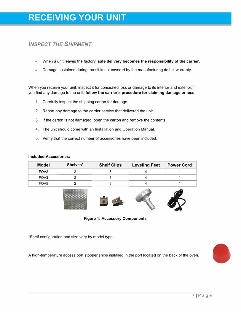
Included Accessories:
Model Shelves* Shelf Clips Leveling Feet Power Cord FOV2 2 8 4 1 FOV3 2 8 4 1 FOV5 2 8 4 1
Figure 1: Accessory Components
*Shelf configuration and size vary by model type.
A high-temperature access port stopper ships installed in the port located on the back of the oven.
8 | P a g e
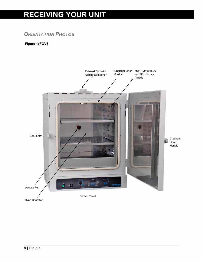
Figure 1: FOV5
RECEIVING YOUR UNIT
ORIENTATION PHOTOS
Exhaust Port with Sliding Dampener
Main Temperature and OTL Sensor Probes
Door Latch Chamber Door Handle
Control Panel
Chamber Liner Gasket
Access Port
Oven Chamber

9 | P a g e
Figure 2: FOV3
RECEIVING YOUR UNIT
Exhaust Port with Sliding Dampener
Main Temperature and OTL Sensor Probes
Door Latch Chamber Door Handle
Control Panel
Chamber Liner Gasket
Access Port
Oven Chamber

10 | P a g e
Figure 3: FOV2
RECEIVING YOUR UNIT
Door Latch Chamber Door Handle
Control Panel
Access Port
Oven Chamber
Exhaust Port with Sliding Dampener
Chamber Liner Gasket
Main Temperature and OTL Sensor Probes (Under Shelf)
11 | P a g e
RECEIVING YOUR UNIT
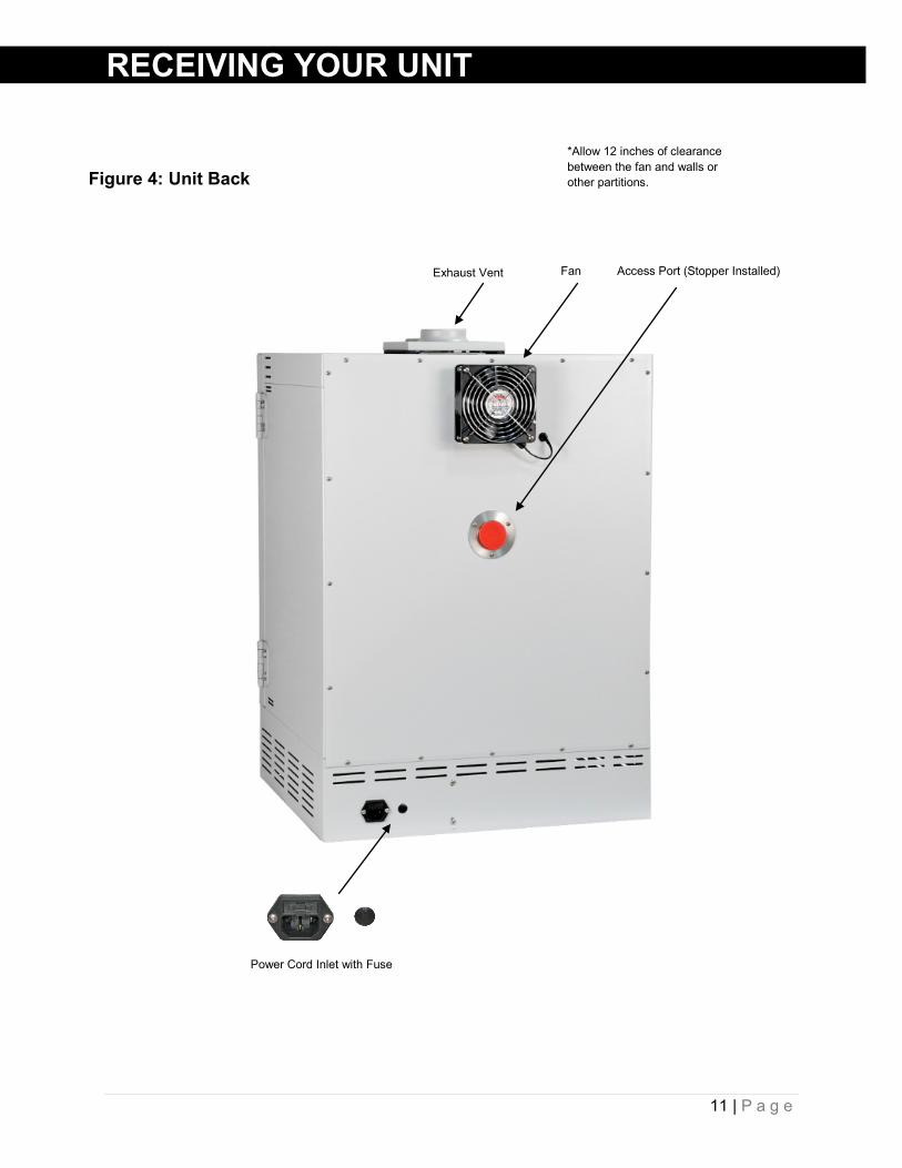
Figure 4: Unit Back
Exhaust Vent Fan Access Port (Stopper Installed)
Power Cord Inlet with Fuse
*Allow 12 inches of clearance between the fan and walls or other partitions.

12 | P a g e
RECEIVING YOUR UNIT
RECORD DATA PLATE INFORMATION Locate the data plate on the back of the oven adjacent to the power inlet. The data plate contains the oven model number and serial number. Technical support and your distributor will need these numbers in order to assist you in the future. Record the data plate information here.
Date Plate Information
Model Number
Serial Number
TEMPERATURE REFERENCE SENSOR DEVICE The oven does not come with a temperature reference device. A reference sensor device must be purchased separately for performing accuracy verifications and calibrations of the oven temperature display.
The reference device must be accurate to at least 1°C, and should be regularly calibrated, preferably by a third party.
For best results, use a digital device with wired-connected temperature sensing probe. For example, a wire thermocouple probe that can be introduced into the oven chamber, leaving the device outside. Readings taken from outside the unit avoid chamber door openings during verifications and calibrations and eliminate subsequent waits for the chamber temperature to re-stabilize before proceeding.
Select a probe suitable for the application temperature you will be calibrating or verifying the display accuracy at.
Alcohol thermometers are insufficient for conducting accurate verifications and calibrations. Do not use a mercury thermometer. Never place a mercury thermometer in the oven chamber.
13 | P a g e
INSTALLATION
INSTALLATION CHECKLIST Carry out the procedures and steps listed below to install the oven in a new workspace location and prepare it for use. All procedures are found in the Installation section of this manual.
Pre-Installation Check that the required ambient conditions, ventilation, and spacing for the oven are
met, page 14.
• Unit dimensions may be found on page 39
Check for performance-disrupting heat and cold sources in the environment, page 14
Check that a suitable electrical outlet and power supply is present, page 15
Install the Oven in a suitable workspace location Review the lifting and handling instructions, page 15
Install the oven in its workspace location, page 15
Make sure the oven is level, page 16
Set up the Oven for use Clean the oven chamber if needed, page 16
Install the shelving in the oven chamber, page 17
Verify that the rubber stopper is installed in the access port inside the incubation chamber, page 17

14 | P a g e
INSTALLATION
REQUIRED AMBIENT CONDITIONS This oven is intended for use indoors, at room temperatures between 15°C and 40°C (59°F and 104°F), at no greater than 80% Relative Humidity (at 25°C / 77°F).
Clearances
• Allow 24 inches (60cm) of vertical headspace clearance above the top of the oven for unobstructed airflow and cooling.
o If the oven exhaust will be vented from the workspace through a duct or other channeling, 12 inches (30cm) of vertical clearance will suffice. Make sure the exhaust vent remains unobstructed.
o Do not place objects on top of the oven.
• Allow a minimum of 12 inches (30cm) of horizontal clearance between the oven and any walls or partition.
o Allow at least 12 inches (30cm) from the fan on the back of the oven to the nearest wall or partition. Keep the fan unobstructed at all times.
Operating the unit outside of these conditions may adversely affect its temperature range and stability. For conditions outside of those listed above, please contact your distributor to explore other oven options suited to your laboratory or production environment.
ENVIRONMENTAL DISRUPTION SOURCES When selecting a location to install the unit, consider all environmental conditions that can affect its temperature performance. For example:
• Proximity to other ovens, autoclaves, and any device that produces significant radiant heat
• Heating and cooling ducts, or other sources of fast-moving air currents
• High-traffic areas
• Direct sunlight
15 | P a g e
INSTALLATION
POWER SOURCE REQUIREMENTS When selecting a location for the unit, verify that each of the following requirements is satisfied:
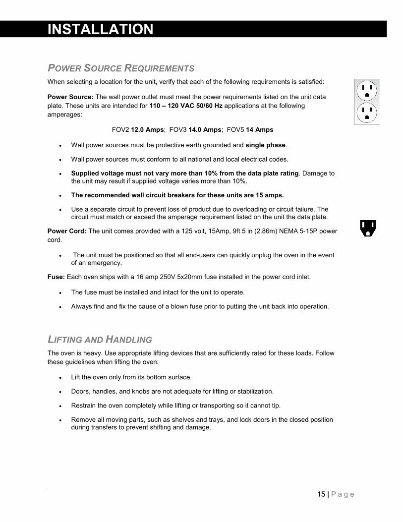
Power Source: The wall power outlet must meet the power requirements listed on the unit data plate. These units are intended for 110 – 120 VAC 50/60 Hz applications at the following amperages:
FOV2 12.0 Amps; FOV3 14.0 Amps; FOV5 14 Amps
• Wall power sources must be protective earth grounded and single phase.
• Wall power sources must conform to all national and local electrical codes.
• Supplied voltage must not vary more than 10% from the data plate rating. Damage to the unit may result if supplied voltage varies more than 10%.
• The recommended wall circuit breakers for these units are 15 amps.
• Use a separate circuit to prevent loss of product due to overloading or circuit failure. The circuit must match or exceed the amperage requirement listed on the unit the data plate.
Power Cord: The unit comes provided with a 125 volt, 15Amp, 9ft 5 in (2.86m) NEMA 5-15P power cord.
• The unit must be positioned so that all end-users can quickly unplug the oven in the event of an emergency.
Fuse: Each oven ships with a 16 amp 250V 5x20mm fuse installed in the power cord inlet.
• The fuse must be installed and intact for the unit to operate.
• Always find and fix the cause of a blown fuse prior to putting the unit back into operation.
LIFTING AND HANDLING The oven is heavy. Use appropriate lifting devices that are sufficiently rated for these loads. Follow these guidelines when lifting the oven:
• Lift the oven only from its bottom surface.
• Doors, handles, and knobs are not adequate for lifting or stabilization.
• Restrain the oven completely while lifting or transporting so it cannot tip.
• Remove all moving parts, such as shelves and trays, and lock doors in the closed position during transfers to prevent shifting and damage.
16 | P a g e
INSTALLATION
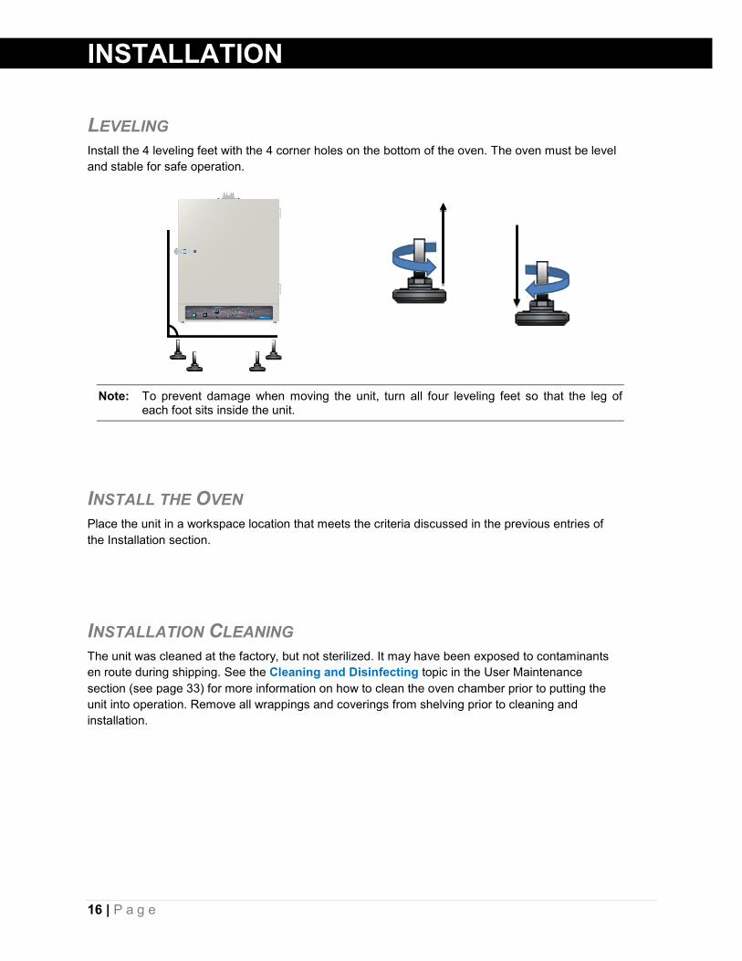
LEVELING Install the 4 leveling feet with the 4 corner holes on the bottom of the oven. The oven must be level and stable for safe operation.
Note: To prevent damage when moving the unit, turn all four leveling feet so that the leg of each foot sits inside the unit.
INSTALL THE OVEN Place the unit in a workspace location that meets the criteria discussed in the previous entries of the Installation section.
INSTALLATION CLEANING The unit was cleaned at the factory, but not sterilized. It may have been exposed to contaminants en route during shipping. See the Cleaning and Disinfecting topic in the User Maintenance section (see page 33) for more information on how to clean the oven chamber prior to putting the unit into operation. Remove all wrappings and coverings from shelving prior to cleaning and installation.

17 | P a g e
INSTALLATION
SHELVING INSTALLATION Perform the following steps to install the FOV shelves:
1. Install 4 clips for each shelf in the slots located on the sides of the chamber interior.
a. Squeeze each clip.
b. Insert the top tabs first, then the bottom tabs using a rocking motion.
2. Place the shelves on the clips.
ACCESS PORT STOPPER Verify the port stopper is installed in the access port on the back of the unit. The oven will not meet its temperature performance specifications without the stopper installed.
The stopper must always be installed on the outside of the oven. Figure 7: Port Stopper in Access Port
Figure 5: Install Clips Figure 6: Place the Shelf

18 | P a g e
INSTALLATION
This page left blank

19 | P a g e
GRAPHIC SYMBOLS
The unit is provided with multiple graphic symbols on its exterior. The symbols identify hazards and the functions of the adjustable components, as well as important notes in the user manual.
Symbol Definition
Indicates that you should consult your user manual for further instructions. Indique que l'opérateur doit consulter le manuel d'utilisation pour y trouver les instructions complémentaires.
Indicates Temperature Repère température
Indicates the Over Temperature Limit system Indique le système de dépassement de temperature
Indicates AC Power Repère le courant alternative
Indicates ( I ) ON and ( O ) OFF I repère de la position MARCHE de l'interrupteur d'alimentation O repère de la position ARRÊT de l'interrupteur d'alimentation
Indicates protective earth ground Repère terre électrique
Indicates UP and DOWN respectively Touches de déplacements respectifs vers le HAUT et le BA
Indicates a Manually Adjustable control Indique un bouton réglable manuellement
Indicates the unit should be recycled (Not disposed of in land-fill) Indique l’appareil doit être recyclé (Ne pas jeter dans une décharge)

20 | P a g e
GRAPHIC SYMBOLS
Symbol Definition
Indicates the timer Indique le minuterie
Start or Stop the Timer Lancer ou arrêter le minuteur
Reset the Timer Réinitialisation de la Minuterie

21 | P a g e
CONTROL PANEL OVERVIEW
Power Switch The green Power Switch controls power to the oven and its systems. When in the ON ( I ) position, the switch illuminates and the oven will heat to and maintain the currently temperature set point.
Timer Switch The black Timer Switch controls power to the timer system. When this switch is in the ON position, the SET TIMER display will illuminate, and the oven can run a timed steady-state heating profile at the current temperature set point. The oven will not heat while the Timer system is on unless a profile is running.
Over Temperature Limit Control (OTL) This graduated dial sets the temperature cutoff limit for the Over Temperature Limit system. The OTL is an independent mechanical heating cutoff that prevents unchecked heating of the oven in the event of a failure of the main temperature controller system. For more details, please see the explanation of the Over Temperature Limit System on page 25 in the Theory of Operation entry.
OTL Light Marked OVER TEMPERATURE ACTIVATED, this light illuminates whenever the OTL System is routing power away from the heating elements. Under normal operating conditions this light should not illuminate.
Figure 8: FOV3, FOV5 Control Panel
Figure 9: FOV2 Control Panel
22 | P a g e
CONTROL PANEL OVERVIEW
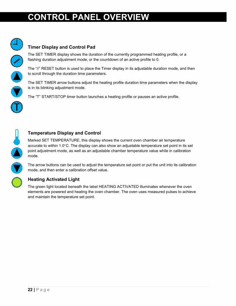
Timer Display and Control Pad
The SET TIMER display shows the duration of the currently programmed heating profile, or a flashing duration adjustment mode, or the countdown of an active profile to 0.
The “//” RESET button is used to place the Timer display in its adjustable duration mode, and then to scroll through the duration time parameters.
The SET TIMER arrow buttons adjust the heating profile duration time parameters when the display is in its blinking adjustment mode.
The “T” START/STOP timer button launches a heating profile or pauses an active profile.
Temperature Display and Control Marked SET TEMPERATURE, this display shows the current oven chamber air temperature accurate to within 1.0°C. The display can also show an adjustable temperature set point in its set point adjustment mode, as well as an adjustable chamber temperature value while in calibration mode.
The arrow buttons can be used to adjust the temperature set point or put the unit into its calibration mode, and then enter a calibration offset value.
Heating Activated Light The green light located beneath the label HEATING ACTIVATED illuminates whenever the oven elements are powered and heating the oven chamber. The oven uses measured pulses to achieve and maintain the temperature set point.

23 | P a g e
OPERATION
OPERATING PRECAUTIONS Warning: The oven is not an explosion-proof unit!
Avertissement: Ce sont des fours pas résistants aux explosions.
1. The oven is not designed to safely contain combustible gasses.
2. Do not place explosive, combustible, or flammable materials into the chamber.
3. The bottom surface of the chamber should not be used as a work surface.
4. Do not operate the oven in an environment with noxious fumes.
5. The oven is provided with a dampened exhaust vent. For safe and efficient oven operation follow these precautions:
a. During normal baking operations, the damper is closed.
b. Outgassed byproducts may be hazardous to or noxious for operating personnel. If either is the case, the oven exhaust should be positively ventilated to a location outside workspace in accordance with national and local regulations.
6. Do not place sealed or filled containers in the oven.
7. Do not place mercury thermometers in the oven.
8. The oven is not designed for use in Class I, II, or III locations as defined by the US National Electric Code.
24 | P a g e
OPERATION THEORY OF OPERATION Heating When powered, the FOV oven chamber heats to and then maintains the currently programmed temperature set point. The oven comes from the factory with a temperature set point of “OFF”. The set point may be adjusted by the end-user using the Set Temperature controls.
Heating is controlled by a microprocessor controller board that stores the temperature set point. The microprocessor senses the chamber air temperature via a solid-state probe located in the airstream on the right wall of the oven chamber. When the processor detects that the chamber temperature has dropped below the temperature set point, it pulses power to a heating element in a recirculation air duct space located above the oven chamber.
The processor employs proportional-integral-derivative analytical feedback-loop functions when measuring and controlling the chamber air temperature levels. PID-controlled heating pulse intensities and lengths are proportional to the difference between the measured chamber temperature and the current set point. The frequency of pulses is derived from the rate of change in the difference. The integral function slows the rate of pulses when the temperature nears the set point to avoid overshooting.
FOV ovens rely on natural heat radiation for cooling.
When the oven is powered, the chamber air temperature cannot go below the ambient room temperature plus the internal waste heat of the oven. Waste heat is generated primarily by the operation of the blower fan motor and the resulting air compression in the duct spaces. In practice, the temperature floor is ambient +20°C.
The oven depends on the operation of the blower fan to maintain temperature uniformity and stability in the chamber.
Air Circulation The oven continually circulates air internally while powered. Air is forced through the small vent holes on the right side of the chamber, blows across the shelf space to the large holes on the left side, and is then pulled up into a heating and recirculation air duct by the action of the blower fan.
The oven is provided with a dampener vent that may be opened or closed using a dampener slide located on the oven top. FOV forced air ovens must be run with the dampener closed in order to achieve the stated temperature performance specifications.
The dampener is intended to speed drying or evaporation rates after the heated portion of an application is complete. Opening the dampener vent while the oven is running may speed the rate of material drying, depending on the nature of your application. However, it also introduces cool air into the chamber while allowing heated air to exit. This will likely impact the temperature performance of the oven.

25 | P a g e
OPERATION
Timed Heating Profile The oven is provided with a Timer subsystem that, when set, runs the oven in a steady-state heating profile at the current temperature set point from 1 minute up to 99 hours, 59 minutes. Allow the oven to heat to temperature prior to launching a profile. Launching a profile with the temperature set point set to 150°C immediately after turning on the oven will result in the first several minutes of the profile spent with the chamber rising from room temperature to 150°C.
When the Timer system is on, the oven will not heat unless a profile of 1 minute or greater has been launched.
The Over Temperature Limit System (OTL) When set, the mechanical OTL heating cutoff system prevents runaway heating in the oven chamber. The OTL operates independently of the microprocessor and is provided with a separate, hydrostatic temperature sensor probe located in the oven chamber. In the event the chamber air temperature exceeds the current OTL setting, the OTL routes power away from the heating elements. The OTL will continue to prevent heating until the temperature drops below its limit setting. The Over Temperature Limit is set by the end-user, typically at approximately 5°C above the application temperature set point.
26 | P a g e
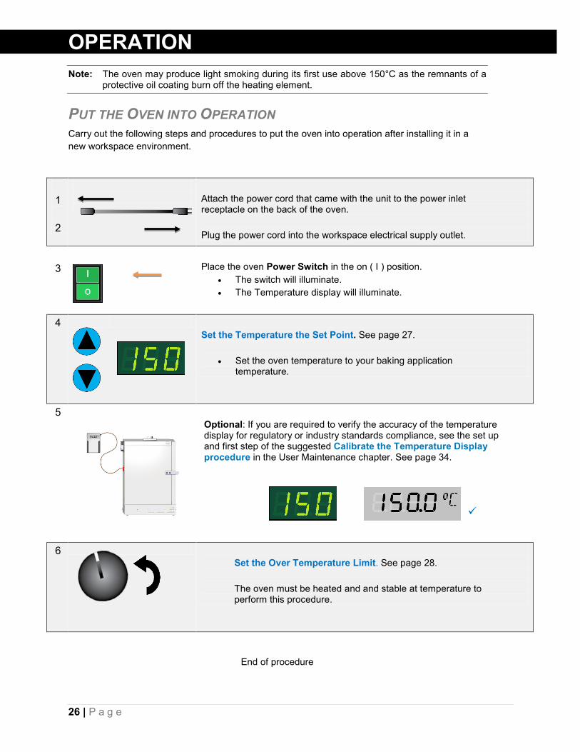
OPERATION Note: The oven may produce light smoking during its first use above 150°C as the remnants of a
protective oil coating burn off the heating element.
PUT THE OVEN INTO OPERATION Carry out the following steps and procedures to put the oven into operation after installing it in a new workspace environment.
End of procedure
1 2
Attach the power cord that came with the unit to the power inlet receptacle on the back of the oven. Plug the power cord into the workspace electrical supply outlet.
3
Place the oven Power Switch in the on ( I ) position.
• The switch will illuminate. • The Temperature display will illuminate.
4 Set the Temperature the Set Point. See page 27.
• Set the oven temperature to your baking application temperature.
5
Optional: If you are required to verify the accuracy of the temperature display for regulatory or industry standards compliance, see the set up and first step of the suggested Calibrate the Temperature Display procedure in the User Maintenance chapter. See page 34.
6 Set the Over Temperature Limit. See page 28. The oven must be heated and and stable at temperature to perform this procedure.

27 | P a g e
OPERATION SET THE OVEN TEMPERATURE SET POINT Adjust the oven temperature set point to that of your application.
End of Procedure
1 Turn the OTL dial clockwise to its max setting, if not already set at max.
• This prevents the heating cutoff system from interfering with this
procedure.
2 Activate the temperature set point adjustment mode.
a. Press and release either of the Set
Temperature arrows
• The display will briefly flash the letters “SP”, then show the flashing, adjustable temperature set point.
Note: The display will automatically exit the adjustment mode after 5 seconds of inactivity, with the last shown set point value saved.
Set Temperature
Set Point Adjustment Mode
Current Set Point
3 Adjust the set point to your application temperature using the Up or Down arrow buttons.
Set Temperature
New Set Point
4 Wait 5 seconds after entering the set point.
• The display will stop flashing. The set point is now saved in the controller.
• The oven will now automatically heat or passively cool to match the set point.
• The display will revert to showing the current chamber air temperature.
Set Temperature
Heating to Set Point
See the Setting the Over Temperature Limit procedure on page 28 for how to set the OTL heating cutoff system once the oven has stabilized at your application temperature set point.
28 | P a g e
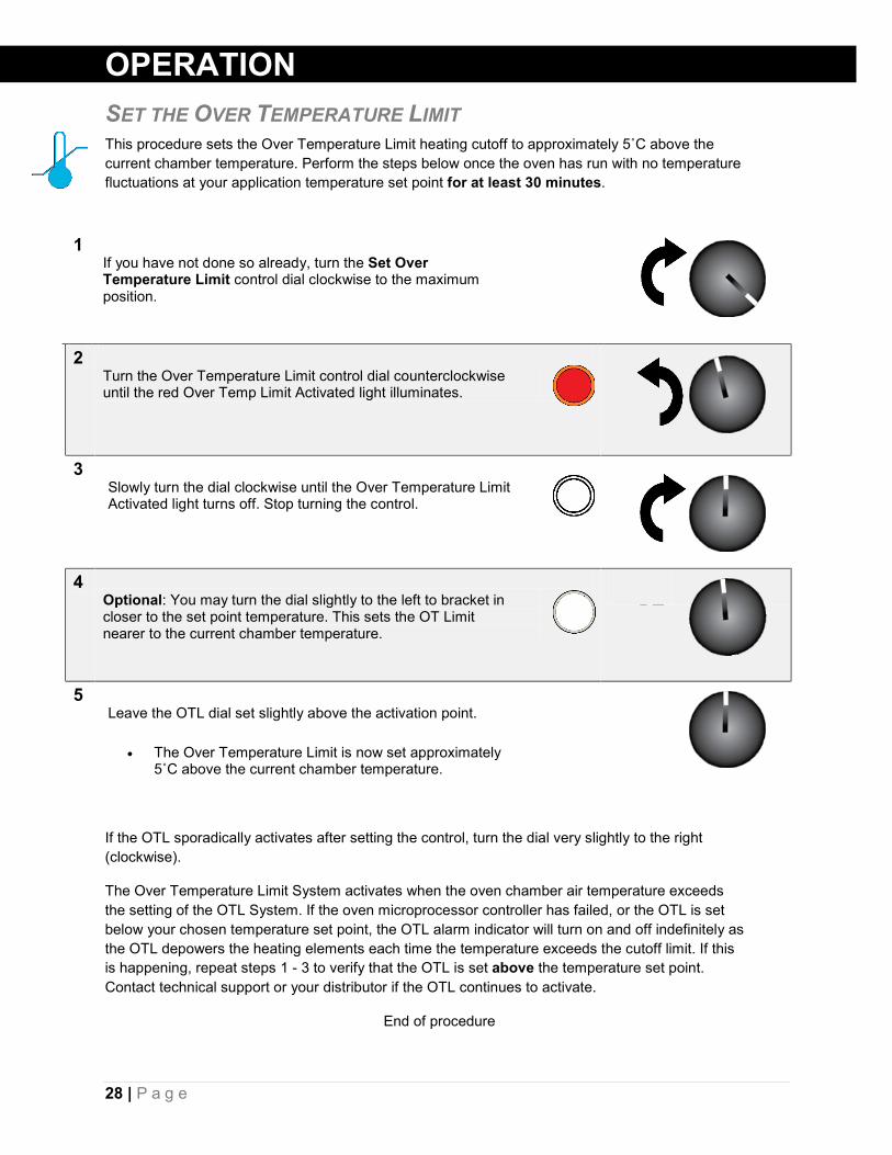
OPERATION SET THE OVER TEMPERATURE LIMIT This procedure sets the Over Temperature Limit heating cutoff to approximately 5˚C above the current chamber temperature. Perform the steps below once the oven has run with no temperature fluctuations at your application temperature set point for at least 30 minutes.
If the OTL sporadically activates after setting the control, turn the dial very slightly to the right (clockwise).
The Over Temperature Limit System activates when the oven chamber air temperature exceeds the setting of the OTL System. If the oven microprocessor controller has failed, or the OTL is set below your chosen temperature set point, the OTL alarm indicator will turn on and off indefinitely as the OTL depowers the heating elements each time the temperature exceeds the cutoff limit. If this is happening, repeat steps 1 - 3 to verify that the OTL is set above the temperature set point. Contact technical support or your distributor if the OTL continues to activate.
End of procedure
1 If you have not done so already, turn the Set Over Temperature Limit control dial clockwise to the maximum position.
2 Turn the Over Temperature Limit control dial counterclockwise until the red Over Temp Limit Activated light illuminates.
3 Slowly turn the dial clockwise until the Over Temperature Limit Activated light turns off. Stop turning the control.
4 Optional: You may turn the dial slightly to the left to bracket in closer to the set point temperature. This sets the OT Limit nearer to the current chamber temperature.
5 Leave the OTL dial set slightly above the activation point.
• The Over Temperature Limit is now set approximately
5˚C above the current chamber temperature.

29 | P a g e
OPERATION
SETTING THE TIMER This procedure enters a heating profile duration in the Timer system. When launched, the profile runs the oven for the duration at the present temperature set point.
Procedure continued on next page
1 Turn on the Timer system.
a. Place the black Timer switch in the On ( I ) position.
• The Timer Display will illuminate, showing the
previously programmed profile duration.
• The oven will cease heating.
Set Timer
1 Minute Profile
2 Place the Timer display in its adjustable set timer mode.
a. Press and hold the Reset button until
the Timer Display begins to blink.
• The illuminated decimal point between the 2nd and 3rd numbers indicates that Hours parameter is selected.
Note: If 5 seconds elapse with no activity on the Arrow Pad buttons, the Timer Display will exit the adjustment mode with the last entered time values saved.
Set Timer
Hours Selected
3
Use the Up or the Down arrow key to adjust the Hour parameter to a setting from 0 to 99.
Set Timer
1 Hour, 1 Minute
4 Advance to the Tens-of-Minutes parameter.
a. Press and hold the Reset button.
• The flashing decimal point will advance to
between the third and fourth numbers, automatically saving the new Hour parameter setting.
Set Timer
Tens of Minutes Selected

30 | P a g e
OPERATION
End of procedure
DRYING RACKS AND OTHER ACCESSORIES • Make sure any accessories used inside the oven chamber, such as drying racks, are
suitable for your application and will not suffer damage when brought to temperature.
• Always set the OTL cutoff system to just above your application temperature set point in order to safeguard accessories against over temperature events.
• The manufacturing defect warranty does not cover damage caused by melted or otherwise overheated accessory items.
Setting the Timer Continued
5
Use the Up or the Down arrow key to set the Tens of Minutes parameter value.
Set Timer
1 Hour, 51 Minutes
6 Advance to the Minutes parameter.
a. Press and hold the Reset button.
• The flashing decimal point will advance to
behind the 4th number, automatically saving the new Tens-of-Minutes parameter setting.
Set Timer
Minutes Selected
7
Use the Up or the Down arrow key to adjust the Minutes parameter value.
Set Timer
1 Hour, 55 Minutes
8 Wait for 5 seconds after entering the new Minutes parameter value.
• The display will exit adjustment mode.
• The Minutes parameter, along with the previous two parameter values are now saved.
Set Timer

31 | P a g e
OPERATION LAUNCH A HEATING PROFILE The oven can be run in a timed steady-state heating profile at the current temperature set point. Allow the oven to come up to temperature prior to launching a profile. See the Setting the Timer procedure on page 29 for how to set the length of the profile.
Note: While the Timer system is on, the oven will not heat unless a profile is running.
End of procedure
1
The Timer switch must be in the ON ( I ) position just prior to launching the profile.
Set Timer
1 Hour, 55 Minute Profile
2 Press the Start/Stop T button to launch the current profile.
• The profile will launch and the TIMER ACTIVATED
indicator will illuminate.
• The Timer Display will start counting down.
• The oven will resume heating.
Set Timer
3 To pause a running profile, press the Start/Stop button.
• The oven will cease heating until the profile is
restarted, reset, or the Timer system is turned off.
• To restart the profile where it left off, press the Start/Stop button again.
Pause Profile
4 The oven will automatically cease heating upon reaching “00:00”.
• To resume manual heating place the
Timer Switch in the OFF ( O ) position.
- Or -
• To launch another profile press the “//” Reset button and enter a new profile, or allow the previous profile to reset automatically after 5 seconds.
Set Timer
Profile Complete
32 | P a g e
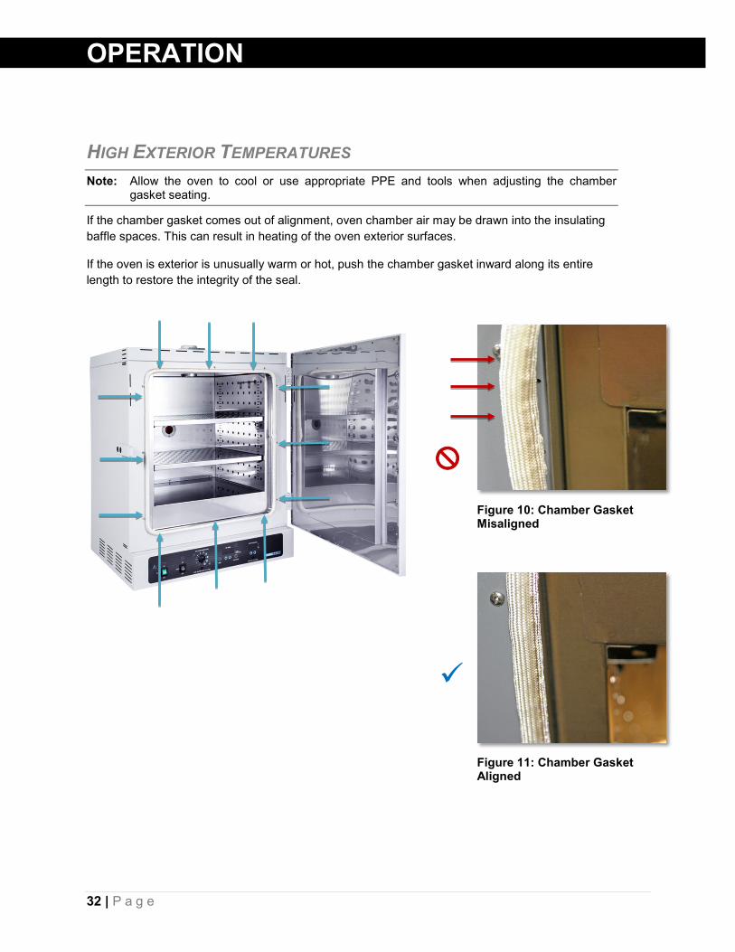
Figure 10: Chamber Gasket Misaligned
Figure 11: Chamber Gasket Aligned
OPERATION
HIGH EXTERIOR TEMPERATURES Note: Allow the oven to cool or use appropriate PPE and tools when adjusting the chamber
gasket seating.
If the chamber gasket comes out of alignment, oven chamber air may be drawn into the insulating baffle spaces. This can result in heating of the oven exterior surfaces.
If the oven is exterior is unusually warm or hot, push the chamber gasket inward along its entire length to restore the integrity of the seal.

33 | P a g e
USER MAINTENANCE
Warning: Prior to maintenance or service on this unit, disconnect the power feed from the power supply.
Avertissement: Avant d'effectuer toute maintenance ou entretien de cet appareil, débrancher le cordon secteur de la source d'alimentation.
CLEANING AND DISINFECTING If a hazardous material or substance has spilled in the unit, immediately initiate your site’s Hazardous Material Spill Containment protocol. Contact your local Site Safety Officer and follow instructions per the site policy and procedures.
• The unit chamber should be cleaned and disinfected prior to first use.
• Periodic cleaning is required.
• Do not use spray on cleaners or disinfectants. These can leak through openings and coat electrical components.
• Consult with the manufacturer or their agent if you have any doubts about the compatibility of decontamination or cleaning agents with the parts of the equipment or with material contained in it.
• Do not use cleaners or disinfectants that contain solvents capable of harming paint coatings or stainless steel surfaces. Do not use chlorine-based bleaches or abrasives; these will damage the chamber liner.
Warning: Never clean the oven with alcohol or flammable cleaners.
Avertissement: Ne jamais nettoyer l'appareil à l'alcool ou avec des nettoyants inflammables.
Cleaning 1. Remove all removable interior components such as shelving and accessories.
2. Clean the unit with a mild soap and water solution, including all corners. Do not use an abrasive cleaner that will damage metal surfaces. Do not use deionized water to rinse or clean with.
3. Rinse with distilled water and wipe dry with a soft cloth.
4. Take special care when cleaning around the Main Temperature and Over Temperature Limit sensor probes on the side of the chamber to prevent damage.
Disinfecting 1. Turn the unit off. Carry out your disinfection protocol.
2. If allowed by your protocol, remove all shelving. Disinfect all corners. Take special care not to damage the temperature sensor probes when disinfecting.
3. Disinfect the unit using commercially available disinfectants that are non-corrosive, non-abrasive, and suitable for use on stainless steel surfaces. Contact your Site Safety Officer for detailed information on the disinfectants compatible with your study or production protocol.
34 | P a g e
USER MAINTENANCE CALIBRATE THE TEMPERATURE DISPLAY Note: Please see the Reference Sensor Device entry on page 12 for the minimum device requirements.
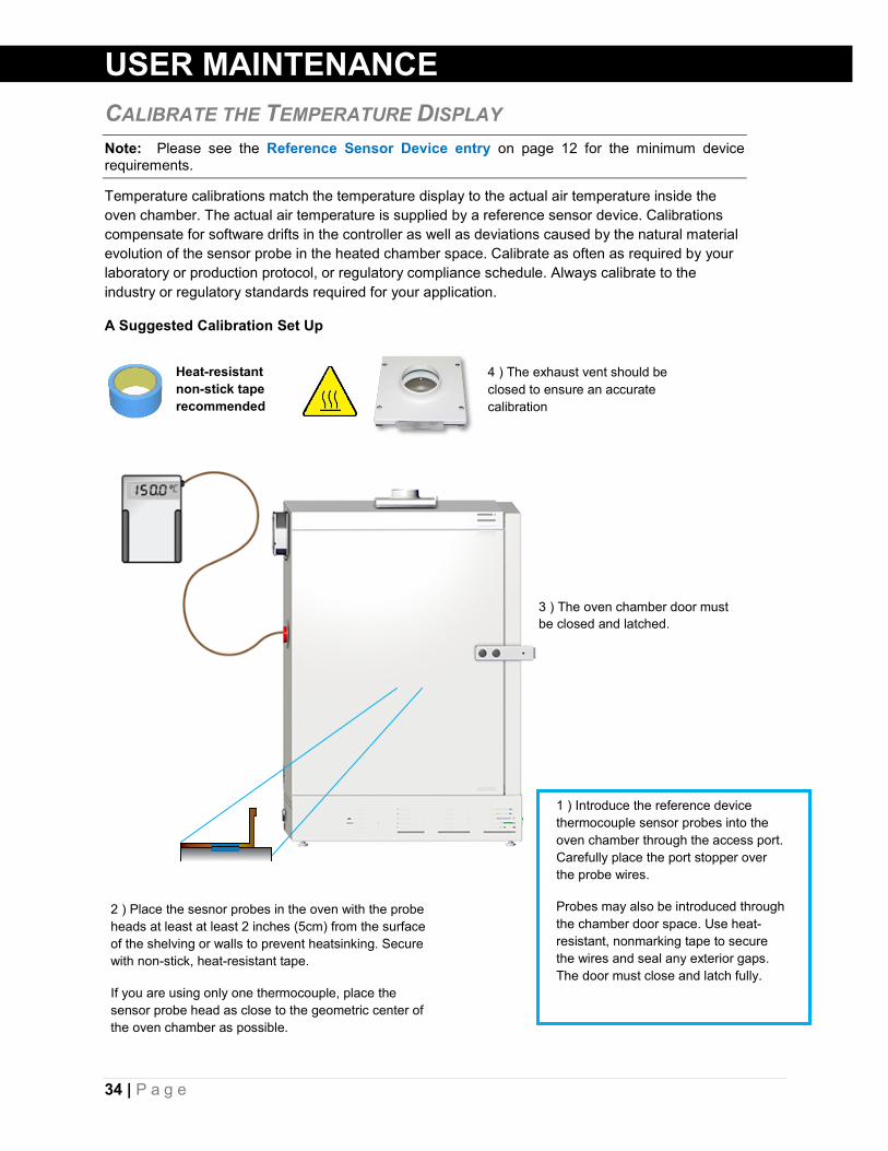
Temperature calibrations match the temperature display to the actual air temperature inside the oven chamber. The actual air temperature is supplied by a reference sensor device. Calibrations compensate for software drifts in the controller as well as deviations caused by the natural material evolution of the sensor probe in the heated chamber space. Calibrate as often as required by your laboratory or production protocol, or regulatory compliance schedule. Always calibrate to the industry or regulatory standards required for your application.
A Suggested Calibration Set Up
3 ) The oven chamber door must be closed and latched.
2 ) Place the sesnor probes in the oven with the probe heads at least at least 2 inches (5cm) from the surface of the shelving or walls to prevent heatsinking. Secure with non-stick, heat-resistant tape.
If you are using only one thermocouple, place the sensor probe head as close to the geometric center of the oven chamber as possible.
Heat-resistant non-stick tape recommended
1 ) Introduce the reference device thermocouple sensor probes into the oven chamber through the access port. Carefully place the port stopper over the probe wires.
Probes may also be introduced through the chamber door space. Use heat-resistant, nonmarking tape to secure the wires and seal any exterior gaps. The door must close and latch fully.
4 ) The exhaust vent should be closed to ensure an accurate calibration

35 | P a g e
Begin Calibration
USER MAINTENANCE 5 ) Heat up and stabilization period.
• The oven chamber must be stable at temperature in order to perform an accurate calibration.
• The temperature is considered stabilized when the oven chamber has operated at your calibration temperature for at least 30 minutes with no fluctuations of ±0.3°C or greater.
Figure 12: Oven Chamber Heat Up and Stabilization Phases
Continued on next page
Suggested Calibration Procedure
1 Once the chamber has stabilized with no fluctuations of 0.3˚C or greater, compare the reference temperature device and chamber temperature display readings.
a. If the readings are the same, or the difference between the two (2) falls within the acceptable range of your protocol, the display is accurately showing the chamber temperature. The Temperature Calibration procedure is now complete.
b. See Step 2 if a difference falls outside the acceptable range
of your protocol.
Reference Device
Set Temperature
2
The display requires calibration. Advance to Step 3.
• If the door was opened to check a reference device temperature inside the chamber wait 15 minutes after the reference device reading stops fluctuating before proceeding.
Reference Device
Set Temperature
150°C
Start
30 Minute Minimum Stability Period
Heat Up to 150°C:
~ 24 Minutes Fluctuations (Exaggerated)

36 | P a g e
USER MAINTENANCE
Procedure continued on next page
Calibration continued
3 Place the oven in temperature calibration mode.
a. Press and hold both the UP and DOWN arrow
buttons simultaneously.
• The Temperature Display will show the letters “C O”, then begin flashing the current temperature value.
Note: If an arrow key is not pressed for five seconds, the Temperature Display will cease flashing, and store the last displayed value as the new current chamber temperature value.
Set Temperature
Set Temperature
Current Temp. Value
4
Adjust the current temperature value to match the reference device.
a. Use the the UP and DOWN arrow buttons.
Set Temperature
Corrected
Reference Device
5 After entering the correction adjustment, wait 5 seconds.
• The temperature display will cease flashing and store the correction as an offset.
• The oven will now begin heating or
allow itself to cool in order to reach your set point with the corrected display value.
Set Temperature
Heating with Corrected
Value
6 Wait for 30 minutes for the oven to stabilize with no fluctuations of ±0.3˚C or greater after the oven has achieved the set point with the corrected display adjustment.
• Failure to wait until the unit is fully stabilized will result in an inaccurate oven display reading.
Set Temperature

37 | P a g e
USER MAINTENANCE
End of procedure
Calibration continued
7 Once the temperature has stabilized, compare the reference device and the oven display temperature readings.
a. If the readings are the same, or the difference between the two falls within the acceptable range of your protocol, the oven is calibrated for temperature.
b. The Temperature Calibration procedure is complete.
Reference Device
Set Temperature
8 If the two readings still fall outside the acceptable range of your protocol, repeat steps 2 – 7 up to two more times.
• Three calibrations attempts may be required to
successfully calibrate ovens more than ± 2⁰C out of calibration.
Reference Device
Set Temperature
If the temperature readings of the oven and the reference device fall outside your protocol after three calibration attempts, contact Technical Support or your distributor for assistance.
38 | P a g e
USER MAINTENANCE
DOOR COMPONENTS AND SEAL Periodically, inspect the door latch, trim, and catch for alignment. Check the chamber liner gasket located on the oven door frame at least once per year for signs of fraying, brittleness, or tearing. Failure to maintain the integrity of the door system shortens the lifespan of the oven and may adversely impact chamber temperature uniformity and stability.
ELECTRICAL COMPONENTS Electrical components do not require maintenance. If the unit electrical systems fail to operate as specified, please contact your distributor or Technical Support for assistance.
39 | P a g e
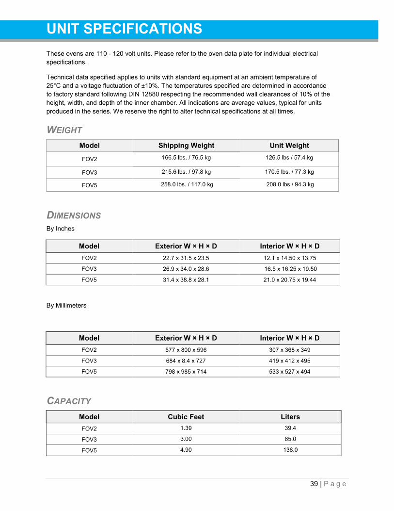
UNIT SPECIFICATIONS These ovens are 110 - 120 volt units. Please refer to the oven data plate for individual electrical specifications.
Technical data specified applies to units with standard equipment at an ambient temperature of 25°C and a voltage fluctuation of ±10%. The temperatures specified are determined in accordance to factory standard following DIN 12880 respecting the recommended wall clearances of 10% of the height, width, and depth of the inner chamber. All indications are average values, typical for units produced in the series. We reserve the right to alter technical specifications at all times.
WEIGHT Model Shipping Weight Unit Weight
FOV2 166.5 lbs. / 76.5 kg 126.5 lbs / 57.4 kg
FOV3 215.6 lbs. / 97.8 kg 170.5 lbs. / 77.3 kg
FOV5 258.0 lbs. / 117.0 kg 208.0 lbs / 94.3 kg
DIMENSIONS By Inches
Model Exterior W × H × D Interior W × H × D FOV2 22.7 x 31.5 x 23.5 12.1 x 14.50 x 13.75
FOV3 26.9 x 34.0 x 28.6 16.5 x 16.25 x 19.50
FOV5 31.4 x 38.8 x 28.1 21.0 x 20.75 x 19.44
By Millimeters
Model Exterior W × H × D Interior W × H × D FOV2 577 x 800 x 596 307 x 368 x 349
FOV3 684 x 8.4 x 727 419 x 412 x 495
FOV5 798 x 985 x 714 533 x 527 x 494
CAPACITY Model Cubic Feet Liters FOV2 1.39 39.4
FOV3 3.00 85.0
FOV5 4.90 138.0

40 | P a g e
UNIT SPECIFICATIONS
SHELF CAPACITY BY WEIGHT Model Per Shelf Max Total Load Max No. Shelves FOV2 50 lbs. / 22.7 kg* 100lbs. / 45 kg** 6 Shelves
FOV3 50 lbs. / 22.7 kg* 200lbs. / 91.0 kg*** 7 Shelves
FOV5 50 lbs. / 22.7 kg* 200lbs. / 91.0 kg*** 9 Shelves
*50lbs / 22.7kgs with weight evenly distributed across the shelf. **100lbs / 45.0kgs total load for the FOV2 shelves. Exceeding this limit risks damaging the chamber liner. *** 200lbs / 91.0kgs total load for the FOV3 and FOV5 shelves. Exceeding this limit risks damaging the chamber liner.
TEMPERATURE Range and Stability
Model Operating Range Stability FOV2 Ambient +20 to 306°C ± 0.2°C @150°C
FOV3 Ambient +20 to 306°C ± 0.3°C @150°C
FOV5 Ambient +20 to 306°C ± 0.3°C @150°C
Uniformity
Model Uniformity @80°C Uniformity @150°C Uniformity @306°C FOV2 + 1.0°C +2.25°C +4.7°C
FOV3 + 1.0°C +1.75°C + 5.0°C
FOV5 + 0.75°C +1.75°C + 4.5°C
Time to Temperature: From an ambient temperature of 20°C.
Model Heat Up to 80°C Heat Up to 150°C Heat Up to 306°C FOV2 8.0 Minutes 20 Minutes 52 Minutes
FOV3 6.0 Minutes 27 Minutes 124 Minutes
FOV5 9.0 Minutes 28 Minutes 130 Minutes
Temperature continued on next page

41 | P a g e
UNIT SPECIFICATIONS Recovery Time: From a 30-second door opening.
Model Recovery to 80°C Recovery to 150° Recovery to 306°C FOV2 1.5 Minutes 4.5 Minutes 14.0 Minutes
FOV3 1.5 Minutes 2.0 Minutes 18.0 Minutes
FOV5 2.0 Minutes 4.0 Minutes 45.0 Minutes
Recovery Time: From a 60-second door opening.
Model Recovery to 80°C Recovery to 150° Recovery to 306°C FOV2 4.0 Minutes 6.0 Minutes 20.0 Minutes
FOV3 2.0 Minutes 4.5 Minutes 36.0 Minutes
FOV5 3.5 Minutes 6.0 Minutes 57.0 Minutes
VENTILATION RATES Velocity
Model Cubic Feet / Minute @80°C Liters per Minute @80°C FOV2 5.6 158.6
FOV3 11.3 320.0
FOV5 15.2 430.4
Air Changes per Hour
Model @80°C
FOV2 330
FOV3 225
FOV5 180
POWER Model AC Voltage Amperage Frequency FOV2 110 - 120 12.0 50/60 Hz
FOV3 110 - 120 14.0 50/60 Hz
FOV5 110 - 120 14.0 50/60 Hz

42 | P a g e
PARTS LIST
Description Parts Number Description Parts Number Adjustable Leveling Feet
2700506
Shelf and 4 Shelf Clips, FOV2
9751227
Door Gasket, FOV2-2, sold by 1.5 feet, requires 5.4ft (1.65 meters)
3450767 (1.5ft)
Shelf and 4 Shelf Clips, FOV3
9751228
Door Gasket, FOV3-2, sold by 1.5 feet, requires 7.5ft (2.3 meters)
3450767 (1.5ft)
Shelf and 4 Shelf Clips, FOV5
9751229
Door Gasket, FOV5-2, sold by 1.5 feet, requires 8.1ft (2.5) meters
3450767 (1.5ft)
Shelf Clip, Individual (1)
1250512
Fuse, T10A 250V 5x20mm (Requires 2 fuses)
300516
Shelf (no Clips), FOV2
5130887
Power Cord 125 volt, 15Amp, 9ft 5 in (2.86m) NEMA 5-15P
1800510
Shelf (no Clips), FOV3
5130888
Port Stopper, High Temperature
7750572
Shelf (no Clips), FOV5
5130890
Ordering If you have the Part Number for an item, you may order it directly from TestEquity. If you are uncertain that you have the correct Part Number, or if you need that specific item, please contact TestEquity Technical Support for help at 877-512-3457, 805-480-0638. Please have the model number and serial number of the unit ready, as Tech Support will need this information to match your unit with its correct part.