TEST SYSTEMS, INC. MIL-STD-1553B
28
TEST SYSTEMS, INC. MIL-STD-1553B RT VALIDATION TEST PROCEDURE
Transcript of TEST SYSTEMS, INC. MIL-STD-1553B

TEST SYSTEMS, INC.
MIL-STD-1553BRT VALIDATION TEST PROCEDURE

06-03-96 1 TEST SYSTEMS, Inc.
RT VALIDATION TEST PROCEDURE
Section Page
I. INTRODUCTION 1II. INITIALIZATION PROCEDURE 4III. 5.1 OFF-LINE ELECTRICAL TESTS 7IV. 5.1 ON-LINE ELECTRICAL TESTS 10V. 5.2.1 REQUIRED PROTOCOL TESTS 20VI. 5.2.2 OPTIONAL PROTOCOL TESTS 23VII. 5.3 NOISE REJECTION TEST 25VIII. TEST TERMINATION 27
APPLICABLE DOCUMENTS:
MIL-STD-1553B, 21 September 1978, "Aircraft Internal Time Division Command/Response MultiplexData Bus" with Notice 2, 8 September 1986.
MIL-HDBK-1553, Notice 1, 24 September 1986, "RT Validation Test Plan".
MIL-HDBK-1553A, Section 100, 1 November 1988.
I. INTRODUCTION
This test procedure is used with the Test Systems, Inc., (TSI) VALIDATE.EXE program for RTValidation Testing. The test procedure explains how to initialize, set up and run the Electrical,Protocol and Noise Rejection Tests in a semi-automated manner. Testing complies with the RTValidation Test Plan, MIL-HDBK-1553 Appendix A (Notice 1), except for the following deviations:
1. The following tests are not run:5.1.1.10 Frequency stability 5.2.1.3.7 Terminal fail-safe
2. Step 6 of 5.2.1.5.3, Reset remote terminal, is changed to repeat step 4 rather than step 5.
3. Not all commands which cause the busy bit to be set are recorded for every test. This can beimpractical in tests where, for example, 10,000 iterations are performed.
A. CUSTOMER INFORMATION
Create a Wordstar customer information textfile that includes the following information: customer,UUT identification, test personnel and equipment used. This textfile will be incorporated into theTest Results File prior to the generation of the test report.

RT VALIDATION TEST PROCEDURE
06-03-96 2 TEST SYSTEMS, Inc.
1. CUSTOMERName: Street Address:City, State, Zip Code:
2. UNIT UNDER TEST IDENTIFICATIONPart Number: Serial Number:Microcode/Software Revision:Terminal Address Used:RT Design Criteria:
3. TEST PERSONNEL
Name Company
4. EQUIPMENT LIST
EQUIPMENT TYPE MANUFACTURERMODEL NO./SERIAL NO.
CALIBRATIONDate Of / Date Due
1553 BUS Tester TSI 122 / 8804111 N/A
Oscilloscope TEK 2445* / TBD TBD
True RMS Voltmeter HP 3400A* / TBD TBD
Impedance Analyzer HP 4192A* / TBD TBD
Function Generator HP 3312A* / TBD N/A
Host Processor ** MIT SYS / TSC 11442 N/A
Monochrome Monitor TBD / TBD N/A
Connection Panel *** TSI 0100 / 900101 N/A
TBD - To Be Determined at the time of testing.
* Suggested equipment or equivalent.
** The host processor uses three TSI cards: the PC/AT PARALLEL I/O CARD is a parallel interfaceused by a PC compatible for high-speed control of the 1553 BUS TESTER; the MANCHESTER CARDis used to transmit a single Manchester encoded word with a controlled delay; the 1553 NOISEGENERATOR CARD provides band-limited additive, random white Gaussian noise required for noiserejection testing.
*** The CONNECTION PANEL provides the equivalent functions of the bus couplers, networks,terminators and cables required for the test configurations. The bus networks are tuned to provide riseand fall times of approximately 100 ns for the short bus and 200 +/- 20 ns for the long bus.
The 1553 BUS TESTER is a multiplex test instrument used for the design, development and final testingof MIL-STD-1553A/B terminals and systems.

RT VALIDATION TEST PROCEDURE
06-03-96 3 TEST SYSTEMS, Inc.
B. TEST INFORMATION
Pass/fail criteria for the Electrical, Protocol and Noise Rejection tests are found in the RT ValidationTest Plan, MIL-HDBK-1553 Appendix A (Notice 1).
Data is analyzed in the software by comparing test results to the pass/fail criteria.
All test results are saved in a Test Results File. At the completion of the Validation tests, this data filewill be used to generate the test report.
For tests with multiple iterations, the test data saved for inclusion in the test report is (1) the data for thefirst failure detected (with a count of the total number of failures and the total number of busyresponses), or (2) the data for the first busy response if there are no failures (with a count of the totalnumber of busy responses) or (3) the first iteration of the test if there are no failures or busy responses.
If at any time during testing a peculiarity in the waveform is present, a picture may be taken and attachedto the test report.

RT VALIDATION TEST PROCEDURE
06-03-96 4 TEST SYSTEMS, Inc.
II. INITIALIZATION PROCEDURE
A. Power up all of the equipment that will be used for testing.
1. Connect the PC/AT PARALLEL I/O CARD CABLE (I/O Cable) from the COMPUTER to the1553 BUS TESTER.
2. Connect the Trigger output on the back of the 1553 BUS TESTER to the oscilloscope (SCOPE)external trigger input and the trigger input on the MANCHESTER CARD (bottom connector).
3. Connect Bus A and Bus B (top and center connectors, respectively) of the MANCHESTERCARD to the Bus A and Bus B connectors on the back of the CONNECTION PANEL.
B. Load the Validation Program. Type VALIDATE and press RETURN twice."Enter data file pathname to use (i.e. VAL_TEST.DAT):" appears.
C. Enter the filename for the Test Results File and RETURN. Now "Select Validation or Control orExit (V,C,E):" will appear.
D. Press C to enter the main menu of CONTROL PROGRAM.
E. Place the cursor at "Restore Tester Parameters".
F. Enter STDVAL1 and press RETURN.
G. Place the cursor in the line "Controller 1 [BC]" on the word "LOAD" and press RETURN.
H. Press ALT-F10 to enter the VALIDATION program.
I. To specify legal/illegal commands for the UUT, do the following:
1. Press F2 and then F7 to configure the program for non-broadcast commands for subaddresses0 to 15. Each of the 32 mode code or word count decimal number positions on a line must bemade legal or illegal for the Transmit and Receive tables.
a. To make all of the mode codes or word counts legal for the line marked by the cursor, pressthe A key. To make all of the mode codes or word counts illegal, press the N key. To makea specific mode code or data word count legal for a command, place the cursor on thedecimal number representation of the mode code or word count, press the + key and thenumber will appear. To make the mode code or word count illegal, press the - key and the"-" symbol will appear in that position.
b. Press TAB to move between the Receive Command and Transmit Command tables. Use thearrow keys to move around in a table.
2. Press F8 to configure the program for non-broadcast commands for subaddresses 16 to 31. Eachof the 32 mode code or word count decimal number positions on each line must be made legalor illegal.

RT VALIDATION TEST PROCEDURE
06-03-96 5 TEST SYSTEMS, Inc.
3. Press F9 to configure the program for broadcast commands for subaddresses 0 to 15. Each of the32 mode code or word count decimal number positions on each line must be made legal orillegal.
4. Press F10 to configure the program for broadcast commands for subaddresses 16 to 31. Each ofthe 32 mode code or word count decimal number positions on each line must be made legal orillegal. Press RETURN to exit to the F2 menu.
J. To specify UUT test parameters on the F2 menu, do the following:
1. Move the cursor to "Bus Selected". Press the SPACE BAR to select the bus to be tested.
2. Move the cursor to "UUT Address" and enter the address.
3. Move the cursor to "Bus Coupling" and press the SPACE BAR to select the form of coupling(Transformer/Direct).
NOTE: The entire Test Plan is run for one form of bus coupling. If the UUT has a second formof coupling, run the Test Plan for the Electrical Tests (required) and Noise Rejection (optional)using a separate data file to generate a second report.
4. Move the cursor to "Operation Mode" and press the SPACE BAR to select the mode ofoperation (Continuous/Halt on Error).
K. Press F5 to specify implementation of UUT functions.
1. Move the cursor to each UUT status bit option and press the SPACE BAR to toggle between"Yes" and "No".
2. Move the cursor to "Broadcast Implemented", "Illegal Command Detection Implemented" and"Data Wrap Around Implemented" and press the SPACE BAR to toggle between "Yes" and"No" for each.
3. Move cursor to "Wrap Around RECEIVE Subaddress" and "Wrap Around TRANSMITSubaddress" and enter the Receive and Transmit Command Subaddresses.
NOTE: If the remote terminal doesn't support the Data Wrap Around test (5.2.1.6), suppress theData Wrap Around test and modify the Output Symmetry test (5.1.1.5) (it uses Data WrapAround).
4. Press RETURN to exit to the F2 menu.
L. Press F6 to specify UUT implementation of mode commands. Move the cursor to each modecommand and press the SPACE BAR to select between "Non & Brdcst", "Not Implemented","NonBrdcst Only" and "Broadcast Only". Press RETURN and then F2 to exit to the main menu.

RT VALIDATION TEST PROCEDURE
06-03-96 6 TEST SYSTEMS, Inc.
NOTES ON TESTING
When a test has been run, press F5 to see the test results. To find errors reported in the test results, pressALT-F10 to enter the CONTROL PROGRAM and search the appropriate menus. Press ALT-F10 toreturn.
To discard test results, use the Clear Function (ALT-F5).
The Pass Criteria Mask Menu is provided to mask selected pass criteria. A conditional pass will begranted for tests that would have failed due to a set status bit or late response but pass with modified passcriteria. To mask pass criteria, press F2 and then F1. Move the cursor to the late response or status bitto be masked and press the SPACE BAR to toggle between "Yes" and "No".
RETURN applies to the key marked ENTER on some keyboards.
To see the text of a specific test in the RT VALIDATION TEST PLAN, place the cursor on the testparagraph number on the main menu and press F3. Press RETURN to exit the text and return to themain menu.
To exit the Validation Program at any time, press CTRL-F2 and then press E. To re-enter theValidation Program, repeat steps A through H.
Suppress a test by moving the cursor to the test paragraph number and pressing ALT-S. An "S" or "s"to the left of a test paragraph number indicates a suppressed test. An "S" means that the test or allsubtests for a set of tests are suppressed. An "s" means that one or more (but not all) of the subtests ofa set of tests have been suppressed.
CTRL-B enables/disables a beeper. The beeper indicates that a test is completed or operator assistanceis required.
The following Help Menu is available by pressing F1:
arrows Move to field in direction of arrowTAB Moves to submenuRETURN Moves to higher level of menu0..9,.,-, Valid characters for numeric fieldsF1,? Displays Help Menu (This display)F2 Selects General Configuration Parameters Menu F3 Displays RT Validation Test Plan textF4 Displays Testing Status in Serial FormatF5;ALT-F5 Displays Test Results; Clears Test ResultsF7;ALT-F7 Enables Test Logging; Disables Test LoggingF8 Selects MANCHESTER CARD Control/Status MenuF9 STARTS the selected test(s)F10 Displays Function Key MapESC ABORTS testingALT-F10 Invokes CONTROL ProgramCTRL-F2 Allows selection of Validation or Control or ExitSPACE BAR Steps some fields (See ALT-S) thru its valid values

RT VALIDATION TEST PROCEDURE
06-03-96 7 TEST SYSTEMS, Inc.
III. 5.1 OFF-LINE ELECTRICAL TESTS
A. 5.1.1.6 OUTPUT NOISE TEST PROCEDURE
1. Use the test configuration in Figure 1 for transformer or direct coupled connections. Connecta cable from the UUT to the appropriate Pad or Load on the CONNECTION PANEL. Use theTC PAD or 70 OHM load for transformer coupling or the DC PAD or 35 OHM load for directcoupling. See Figure 4 of the RT Validation Test Plan for the Pad schematic.
Figure 1. Output Noise Test Configuration
2. Install an isolation plug on the power cable of the RMS voltmeter and connect the voltmeter toone of the UUT's bus inputs.
3. Measure the output voltage of the UUT for power on and power off for both buses.
- - - - Transformer Coupled - - - - - - - - - - Direct Coupled - - - - - -
- - BUS A - - - - BUS B - - - - BUS A - - - - BUS B - -
POWER ONPOWER OFF
______
______
______
______
4. Enter the measured values into the computer for test 5.1.1.6 under Section IV.G.
B. 5.1.1.8.1 POWER ON/OFF NOISE PROCEDURE
1. Use the test configuration in Figure 2 for transformer or direct coupled connections. Connecta cable from the UUT to the appropriate Pad or Load on the CONNECTION PANEL. Use theTC PAD or 70 OHM load for transformer coupling or the DC PAD or 35 OHM load for directcoupling. See Figure 1A of the RT Validation Test Plan for the Pad schematic.
Figure 2. Power On/Off Noise Test Configuration

RT VALIDATION TEST PROCEDURE
06-03-96 8 TEST SYSTEMS, Inc.
2. Connect the oscilloscope (SCOPE) to one bus input of the UUT.
3. Measure the UUT output after turning power on and after turning power off. Repeat themeasurements nine more times.
- - - - Transformer Coupled - - - - - - - - - - Direct Coupled - - - - - -- - BUS A - - - - BUS B - - - - BUS A - - - - BUS B - -
POWER ONPOWER OFF
______
______
______
______
POWER ONPOWER OFF
______
______
______
______
POWER ONPOWER OFF
______
______
______
______
POWER ONPOWER OFF
______
______
______
______
POWER ONPOWER OFF
______
______
______
______
POWER ONPOWER OFF
______
______
______
______
POWER ONPOWER OFF
______
______
______
______
POWER ONPOWER OFF
______
______
______
______
POWER ONPOWER OFF
______
______
______
______
POWER ONPOWER OFF
______
______
______
______
4. Repeat Step 3 for the alternate bus.
5. Enter the maximum values measured for Power On and Power Off into the computer for test5.1.1.8.1 under Section IV.I.
C. 5.1.2.3 INPUT IMPEDANCE TEST PROCEDURE
1. Using the test configuration in Figure 3, connect a cable from one of the transformer coupled ordirect coupled bus inputs of the UUT to the input of the impedance analyzer.
Figure 3. Input Impedance Test Configuration

RT VALIDATION TEST PROCEDURE
06-03-96 9 TEST SYSTEMS, Inc.
2. Measure the impedance magnitude for frequencies of 75 kHz, 100 kHz, 250 kHz, 500 kHz and1 MHz at 1.1 Vrms. Do this with power on and with power off for both buses for transformerand/or direct coupled inputs (where applicable).
- - - - - - - - - - - - - - - - - Transformer Coupled - - - - - - - - - - - - - -
- - - - - - - - Bus A - - - - - - - - - - - - - - - - Bus B - - - - - - - -
f(Hz) Power On Power Off Power On Power Off
75k100k250k500k1.0M
_______________
_______________
_______________
_______________
- - - - - - - - - - - - - - - - Direct Coupled - - - - - - - - - - - - - - - - - - -
- - - - - - - - Bus A - - - - - - - - - - - - - - - - Bus B - - - - - - - -
f(Hz) Power On Power Off Power On Power Off
75k100k250k500k1.0M
_______________
_______________
_______________
_______________
3. Enter the magnitude measurements into the computer for test 5.1.2.3 under Section IV.Q.

RT VALIDATION TEST PROCEDURE
06-03-96 10 TEST SYSTEMS, Inc.
IV. 5.1 ON-LINE ELECTRICAL TESTS
A. ELECTRICAL OUTPUT TEST SETUP
1. Connect equipment as shown in Figure 4 for the selected bus to be tested (A or B). Note: Usethe TC PAD for transformer coupling or the DC PAD for direct coupling. See Figure 1A of theRT Validation Test Plan for the Pad schematic.
a. Connect the oscilloscope differentially to the UUT bus input.b. Connect the 1553 BUS TESTER and the UUT to the appropriate Pad on the CONNECTION
PANEL for the selected bus.
Figure 4. General Electrical Output Test Configuration
2. Press F2. With the cursor on "Bus Selected", press the SPACE BAR to select the desired bus(A/B).
3. Adjust the 1553 BUS TESTER amplitude for the Pad.
a. Press F3 to enter the BC Amplitude Calibration menu.b. Move the cursor to "Protocol BC Transmit Amplitude 2.1 Vpp" for the data bus being tested.c. Press the + or - keys to increase or decrease the measured amplitude to 2.1 Vpp. The
amplitude is measured differentially at the bus input of the UUT with the oscilloscope.d. Press RETURN to exit this menu.e. Press F2 to return to the main menu.
B. 5.1.1.1 OUTPUT AMPLITUDE
1. Move the cursor to "5.1 Electrical Tests". Press TAB to select the Electrical Tests submenu.
2. Press TAB to select"5.1.1 Output Characteristics" submenu.
3. With the cursor on "5.1.1.1 Output Amplitude", press F9 to start sending a valid, legal, transmitcommand to the UUT.
4. Measure the maximum and minimum UUT response peak-to-peak amplitude in mV.
Maximum Output Amplitude (mVpp) ___ Minimum Output Amplitude (mVpp) ___
5. Press the SPACE BAR to stop sending commands to the UUT and press RETURN. Enter themaximum and minimum amplitude values.

RT VALIDATION TEST PROCEDURE
06-03-96 11 TEST SYSTEMS, Inc.
C. 5.1.1.2 RISETIME/FALLTIME
1. Move the cursor to "5.1.1.2 Risetime/falltime" and press TAB.
2. Press F9 and measure the appropriate risetime or falltime of the UUT waveform.
Rise Sync Edge (ns) ___ Fall Sync Edge (ns) ___ Rise Data Edge (ns) ___ Fall Data Edge (ns) ___
3. Press SPACE BAR and RETURN and enter the value.
4. Move the cursor to each prompt and repeat Steps 2 and 3.
5. Press RETURN to exit to the second submenu.
D. 5.1.1.3 ZERO CROSSING STABILITY
1. Move the cursor to "5.1.1.3 Zero Crossing Stability". Press TAB.
2. Press F9. Measure the selected pulse width of the UUT waveform.
Tzcp (500ns) (ns) ___ Tzcn (500ns) (ns) ___ Tzcp (1000ns) (ns) ___ Tzcn (1000ns) (ns) ___ Tzcp (1500ns) (ns) ___ Tzcn (1500ns) (ns) ___ Tzcp (2000ns) (ns) ___ Tzcn (2000ns) (ns) ___
3. Press SPACE BAR and RETURN and enter the value.
4. Move the cursor to each prompt and repeat Steps 2 and 3.
5. Press RETURN to exit to the second submenu.
E. 5.1.1.4 DISTORTION, OVERSHOOT AND RINGING
1. Move the cursor to "5.1.1.4 Distortion, overshoot and ringing" and press F9.
2. Measure the distortion voltage of the UUT waveform.
Distortion Voltage (mV) ___
3. Press SPACE BAR and RETURN and enter the value.
F. 5.1.1.5 OUTPUT SYMMETRY
1. Move the cursor to "5.1.1.5 Output Symmetry" and press TAB.
2. Press F9. Measure the maximum residual voltage (Vr) 2.5 microseconds following the mid-bittransition of the parity bit of the last word in the message.
Symmetry Volt. (0000) (mV) ___ Symmetry Volt. (8000) (mV) ___Symmetry Volt. (5555) (mV) ___ Symmetry Volt. (AAAA) (mV) ___Symmetry Volt. (7FFF) (mV) ___ Symmetry Volt. (FFFF) (mV) ___

RT VALIDATION TEST PROCEDURE
06-03-96 12 TEST SYSTEMS, Inc.
3. Press SPACE BAR and RETURN and enter the value.
4. Move the cursor to each prompt and repeat Steps 2 and 3.
5. Press RETURN to exit to the second submenu.
G. 5.1.1.6 OUTPUT NOISE
1. Move the cursor to "5.1.1.6 Output Noise" and press TAB.
2. Move the cursor to each prompt and enter the output noise measurements previously obtainedfrom Section III.A.
3. Press RETURN to exit to the second submenu. Press F9 to store the values in memory andpress RETURN.
H. 5.1.1.7 OUTPUT ISOLATION
1. Connect the UUT's inactive bus to the appropriate Load on the CONNECTION PANEL. Usethe 70 OHM load for transformer coupling or the 35 OHM load for direct coupling.
2. Move the cursor to "5.1.1.7 Output Isolation" and press TAB.
3. With the cursor on "Active Bus", press F9.
4. Measure the peak-to-peak amplitude on the active bus.
Active Bus (mV) ___ Inactive Bus (mV) ___
5. Press SPACE BAR and RETURN and enter the value.
6. Connect the oscilloscope to the inactive bus.
7. Move the cursor to "Inactive Bus", press F9 and measure the peak-to-peak amplitude on theinactive bus.
8. Press SPACE BAR and RETURN and enter the value.
9. Connect the oscilloscope back to the active bus (see Figure 4).
10. Press RETURN to exit to the second submenu.
I. 5.1.1.8 POWER ON/OFF
1. Move the cursor to "5.1.1.8 Power On/Off" and press TAB.
2. With the cursor on "5.1.1.8.1 Power On/Off Noise", press TAB.
3. Move the cursor to each prompt and enter the maximum measurements for power on noise andpower off noise previously obtained from Section III.B.
4. Press RETURN to exit to the third submenu. Press F9 to store the values in memory and pressRETURN.

RT VALIDATION TEST PROCEDURE
06-03-96 13 TEST SYSTEMS, Inc.
5. Move the cursor to "5.1.1.8.2 Power On Response" and press F9.
6. As directed on the screen, power off the UUT, press RETURN and then power on the UUT.(This test is run 10 times or until a failure occurs.)
7. Press RETURN to exit to the second submenu.
J. 5.1.1.9 TERMINAL RESPONSE TIME
1. Move the cursor to"5.1.1.9 Terminal Response Time". Press TAB.
2. Press F9. Measure the maximum response time.
Transmit Response Time (ns) ___ RT-UUT Response Time (ns) ___Receive Response Time (ns) ___ Mode Command Response (ns) ___
3. Press SPACE BAR and RETURN and enter the value.
4. Move the cursor to each prompt and repeat Steps 2 and 3.
5. Press RETURN twice to exit to the first submenu.
K. 5.1.1.10 FREQUENCY STABILITY
This test is not run, but the requirements can be satisfied by analysis. See Section 4.1 of the RTValidation Test Plan.
L. 5.1.2.1.3 RISE AND FALL TIME
1. Connect the equipment as shown in Figure 5 or Figure 6 for the bus to be tested. Connect the1553 BUS TESTER and the UUT to the appropriate short bus connectors on the CONNECTIONPANEL for transformer coupling or direct coupling. See Figure 1B of the RT Validation TestPlan for the General Bus Configuration.
Zo = characteristic impedance.
Figure 5. Rise/Fall Time Transformer Coupled Configuration

RT VALIDATION TEST PROCEDURE
06-03-96 14 TEST SYSTEMS, Inc.
Figure 6. Rise/Fall Time Direct Coupled Configuration
2. Press F2. With the cursor on "Bus Selected", press the SPACE BAR to select the desired bus(A/B).
3. Adjust the 1553 BUS TESTER amplitude to the test configuration.
a. Press F3 to enter the BC Amplitude Calibration menu.b. Move the cursor to "Protocol BC Transmit Amplitude 2.1 Vpp" for the data bus being tested.c. Press the + or - keys to increase or decrease the measured amplitude to 2.1 Vpp. The
amplitude is measured differentially at the bus input of the UUT with the oscilloscope.d. Press RETURN to exit this menu.e. Press F2 to return to the Electrical Tests submenu.
4. Move the cursor to the "5.1.2 Input Characteristics" and press TAB twice to select the thirdsubmenu.
5. Move the cursor to "5.1.2.1.3 Rise and Fall Time". Press F9 to perform Sinusoidal (5.1.2.1.3.1)and Trapezoidal (5.1.2.1.3.2) waveform tests.
6. Press RETURN four times to exit to the highest level of the main menu.
NOTE
Repeat the above tests (IV. A. through L.) for the alternate bus. If both buses have been tested,proceed to COMMON MODE REJECTION.

RT VALIDATION TEST PROCEDURE
06-03-96 15 TEST SYSTEMS, Inc.
M. 5.1.2.2 COMMON MODE REJECTION
1. Connect the equipment as shown in Figure 7 or Figure 8 (Figure 6A or Figure 6B in the RTValidation Test Plan, respectively) for transformer coupling or direct coupling for the bus to betested. This test uses special center-tapped (*CT) bus couplers (transformer coupling) or specialcenter-tapped (*CT) terminating resistors (direct coupling). If the test fails, connect a smallcapacitor (approximately 47 pf) at the UUT stub connection from the high side to the shield tocompensate for the higher capacitance in the connectors from the low side to the shield. Thiscapacitance differential creates a differential signal from the applied common mode signal.
a. Connect the 1553 BUS TESTER and the UUT to the appropriately coupled long busconnectors on the CONNECTION PANEL for one bus.
b. Connect the Function Generator to the appropriate common mode input on theCONNECTION PANEL (BNC connector) for the bus being tested.
NOTE: It is only necessary to test one form of coupling per bus.
M = MANCHESTER CARD Bus A/B output. Zo = characteristic impedance.
Figure 7. Common Mode Rejection Transformer Coupled Configuration

RT VALIDATION TEST PROCEDURE
06-03-96 16 TEST SYSTEMS, Inc.
Figure 8. Common Mode Rejection Direct Coupled Configuration
2. Press F2. With the cursor on "Bus Selected", press the SPACE BAR to select the desired bus(A/B).
3. Adjust the 1553 BUS TESTER amplitude to the test configuration.
a. Press F3 to enter the BC Amplitude Calibration menu.b. Move the cursor to "CS Amplitude Limit 0.86 Vpp" for the data bus being tested.c. Press the + or - keys to increase or decrease the measured amplitude to 0.86 Vpp. The
amplitude is measured differentially at the bus input of the UUT with the oscilloscope.d. Press RETURN to exit this menu.e. Press F2 to return to the main menu.
4. With the cursor on "5.1 Electrical Tests", press TAB, move the cursor to "5.1.2 InputCharacteristics" and press TAB again.
5. Move the cursor to "5.1.2.2 Common Mode Rejection" and press F9.
6. With the cursor on "Common Mode Rejection (+10V)", adjust the function generator to +10VDC as measured on the oscilloscope line to shield. Note: This is not a differential measurement.
7. Press RETURN to start this test. It will stop after 90 sec.
8. With the cursor on "Common Mode Rejection (-10V)", adjust the function generator to -10V DCas measured on the oscilloscope line to shield.
9. Press RETURN. The test will stop after 90 sec.
10. With the cursor on "Common Mode Rejection (+/- 10V)", adjust the function generator to+/-10V AC (20 Vpp) as measured on the oscilloscope line to shield.
RT VALIDATION TEST PROCEDURE
06-03-96 17 TEST SYSTEMS, Inc.
11. Press RETURN to start this test and manually sweep the frequency of the signal generator from1hz to 2Mhz during the 90 sec for the test.
12. Press RETURN three times to exit to the highest level of the main menu.
NOTE
Repeat the above tests (IV.M.) for the alternate bus. If both buses have been tested, disconnectthe Function Generator and proceed to ELECTRICAL INPUT TEST SETUP.
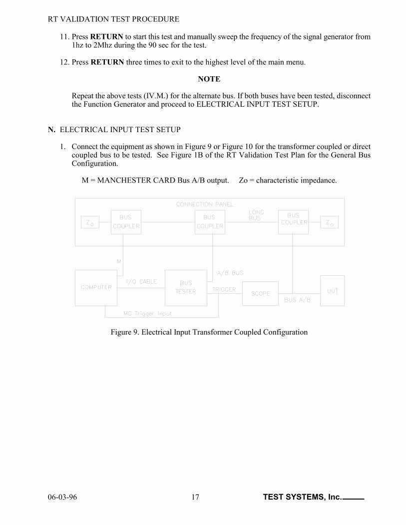
N. ELECTRICAL INPUT TEST SETUP
1. Connect the equipment as shown in Figure 9 or Figure 10 for the transformer coupled or directcoupled bus to be tested. See Figure 1B of the RT Validation Test Plan for the General BusConfiguration.
M = MANCHESTER CARD Bus A/B output. Zo = characteristic impedance.
Figure 9. Electrical Input Transformer Coupled Configuration

RT VALIDATION TEST PROCEDURE
06-03-96 18 TEST SYSTEMS, Inc.
Figure 10. Electrical Input Direct Coupled Configuration
2. Press F2. With the cursor on "Bus Selected", press the SPACE BAR to select the desired bus(A/B).
3. Adjust the 1553 BUS TESTER amplitude to the test configuration.
a. Press F3 to enter the BC Amplitude Calibration menu.b. Move cursor to "NR Amplitude Limit 0.20 Vpp" for the data bus being tested.c. Press the + or - keys to increase or decrease the measured amplitude to 0.20 Vpp. The
amplitude is measured differentially at the bus input of the UUT with the oscilloscope.d. Move the cursor to the other voltages and adjust them.e. Press RETURN to exit this menu.
4. Adjust the 1553 BUS TESTER Zero Crossing Distortion (ZCD) to the test configuration.
a. Press F4 to enter the ZCD Calibration menu. b. Move the cursor to the "+ 180 nsecs" for the bus being tested.c. Press the + or - keys to increase or decrease the first zero crossing deviation (ZCD) to + 180
ns. The ZCD is measured with the oscilloscope differentially at the input to the UUT.d. Move the cursor to the other voltages and adjust them.e. Press RETURN to exit this menu.f. Press F2 to return to the main menu.
O. 5.1.2.1.1 ZERO CROSSING DISTORTION
1. With the cursor on "5.1 Electrical Tests", press TAB, move the cursor to "Input Characteristics"and press TAB three times to select the Zero Crossing submenu.
2. With the cursor on "Min ZCD", press F9.

RT VALIDATION TEST PROCEDURE
06-03-96 19 TEST SYSTEMS, Inc.
3. As directed on the screen, measure the value, press the SPACE BAR, enter the value and pressRETURN twice.
Min ZCD (ns) _______ Max ZCD (ns) _______
4. Move the cursor to "Max ZCD", press F9 and repeat step 3.
5. Move the cursor to "Plus 150 ns ZCD" and press F9.
6. As directed on the screen, enter the number of data words and press RETURN. When the testis finished, press RETURN.
7. Move cursor to "Minus 150 ns ZCD", press F9 and repeat step 6.
8. Press RETURN to exit to the third submenu.
P. 5.1.2.1.2 AMPLITUDE VARIATIONS
1. Move the cursor to "5.1.2.1.2 Amplitude Variations" and press TAB to select the fourthsubmenu.
2. With the cursor on "First Clear Status", press F9.
3. As directed by the screen messages, measure the peak-to-peak amplitude, press the SPACEBAR, enter the measured value and press RETURN twice.
First Clear Status (mV) ______ First No Response (mV) ______
4. Move the cursor to "First No Response," press F9 and repeat step 3.
5. Press RETURN twice to exit to the second submenu.
Q. 5.1.2.3 INPUT IMPEDANCE
1. Move the cursor to the "5.1.2.3 Input Impedance" and press TAB twice to enter "Power ON"measurements.
2. Move the cursor to each prompt and enter the magnitude and phase angle measurements obtainedfrom Section III.C.
3. Press RETURN and then press F9 to store the values in memory.
4. Press RETURN, move the cursor to "Power OFF" and press TAB.
5. Repeat steps 2 and 3 to enter "Power OFF" measurements.
6. Press the RETURN four times to exit to the main menu.
NOTE
Repeat the above tests (IV. N. through Q.) for the alternate bus. If both buses have been tested,proceed to REQUIRED PROTOCOL TESTS.

RT VALIDATION TEST PROCEDURE
06-03-96 20 TEST SYSTEMS, Inc.
V. 5.2.1 REQUIRED PROTOCOL TESTS
A. Connect the equipment as shown in Figure 11 or Figure 12 for the transformer coupled or directcoupled buses to be tested. See Figure 1B of the RT Validation Test Plan for the General BusConfiguration. The oscilloscope is not required for running Protocol tests but may be connected tothe monitor outputs (MON) on the back of the 1553 BUS TESTER to observe bus traffic.
NOTE: It is only necessary to test one form of coupling per bus.
M = MANCHESTER CARD Bus A/B output. Zo = characteristic impedance.
Figure 11. Protocol Tests Transformer Coupled Configuration

RT VALIDATION TEST PROCEDURE
06-03-96 21 TEST SYSTEMS, Inc.
Figure 12. Protocol Tests Direct Coupled Configuration
B. Press F2. With the cursor on "Bus Selected", press the SPACE BAR to select the desired bus (A/B).
C. Adjust the 1553 BUS TESTER amplitude to the test configuration.
1. Press F3 to enter the BC Amplitude Calibration menu.2. Move the cursor to "Protocol BC Transmit Amplitude 2.1 Vpp" for Bus A.3. Press the + or - keys to increase or decrease the measured amplitude to 2.1 Vpp. The amplitude
is measured differentially at the bus input of the UUT with the oscilloscope.4. Move the cursor to "Protocol BC Transmit Amplitude 2.1 Vpp" for Bus B and repeat step 3.5. Press RETURN to exit this menu.6. Press F2 to return to the main menu.
D. Move the cursor to "5.2 Protocol Tests" and press TAB.
E. With the cursor on "5.2.1 Required Protocol Tests", press F9 to run all unsuppressed tests.
NOTE: When running the tests, follow the directions of the messages at the bottom of the screen.
RT VALIDATION TEST PROCEDURE
06-03-96 22 TEST SYSTEMS, Inc.
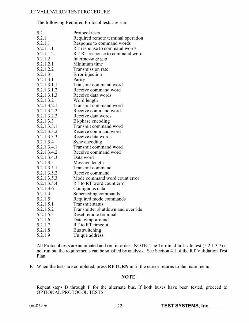
The following Required Protocol tests are run:
5.2 Protocol tests 5.2.1 Required remote terminal operation5.2.1.1 Response to command words 5.2.1.1.1 RT response to command words5.2.1.1.2 RT-RT response to command words 5.2.1.2 Intermessage gap 5.2.1.2.1 Minimum time5.2.1.2.2 Transmission rate 5.2.1.3 Error injection 5.2.1.3.1 Parity 5.2.1.3.1.1 Transmit command word 5.2.1.3.1.2 Receive command word 5.2.1.3.1.3 Receive data words 5.2.1.3.2 Word length 5.2.1.3.2.1 Transmit command word 5.2.1.3.2.2 Receive command word 5.2.1.3.2.3 Receive data words 5.2.1.3.3 Bi-phase encoding 5.2.1.3.3.1 Transmit command word 5.2.1.3.3.2 Receive command word 5.2.1.3.3.3 Receive data words 5.2.1.3.4 Sync encoding 5.2.1.3.4.1 Transmit command word 5.2.1.3.4.2 Receive command word 5.2.1.3.4.3 Data word 5.2.1.3.5 Message length 5.2.1.3.5.1 Transmit command 5.2.1.3.5.2 Receive command 5.2.1.3.5.3 Mode command word count error 5.2.1.3.5.4 RT to RT word count error 5.2.1.3.6 Contiguous data 5.2.1.4 Superseding commands 5.2.1.5 Required mode commands 5.2.1.5.1 Transmit status 5.2.1.5.2 Transmitter shutdown and override 5.2.1.5.3 Reset remote terminal 5.2.1.6 Data wrap-around 5.2.1.7 RT to RT timeout 5.2.1.8 Bus switching 5.2.1.9 Unique address
All Protocol tests are automated and run in order. NOTE: The Terminal fail-safe test (5.2.1.3.7) isnot run but the requirements can be satisfied by analysis. See Section 4.1 of the RT Validation TestPlan.
F. When the tests are completed, press RETURN until the cursor returns to the main menu.
NOTE
Repeat steps B through F for the alternate bus. If both buses have been tested, proceed toOPTIONAL PROTOCOL TESTS.

RT VALIDATION TEST PROCEDURE
06-03-96 23 TEST SYSTEMS, Inc.
VI. 5.2.2 OPTIONAL PROTOCOL TESTS
A. Connect the equipment as shown in Figure 11 or Figure 12 for the transformer coupled or directcoupled buses to be tested. See Figure 1B of the RT Validation Test Plan for the General BusConfiguration. The oscilloscope is not required for running Protocol tests but may be connected tothe monitor outputs (MON) on the back of the 1553 BUS TESTER to observe bus traffic.
NOTE: It is only necessary to test one form of coupling per bus.
B. Press F2. With the cursor on "Bus Selected", press the SPACE BAR to select the desired bus (A/B).
C. Adjust the 1553 BUS TESTER amplitude to the test configuration.
1. Press F3 to enter the BC Amplitude Calibration menu.2. Move the cursor to "Protocol BC Transmit Amplitude 2.1 Vpp" for Bus A.3. Press the + or - keys to increase or decrease the measured amplitude to 2.1 Vpp. The amplitude
is measured differentially at the bus input of the UUT with the oscilloscope.4. Move the cursor to "Protocol BC Transmit Amplitude 2.1 Vpp" for Bus B and repeat step 3.5. Press RETURN to exit this menu.6. Press F2 to return to the main menu.
D. With the cursor on "5.2 Protocol Tests", press TAB and move the cursor to "5.2.2 OptionalOperation".
E. With the cursor on "5.2.2 Optional Operation", press F9 to run all unsuppressed tests.
NOTE: When running the tests, follow the directions of the messages at the bottom of the screen.
RT VALIDATION TEST PROCEDURE
06-03-96 24 TEST SYSTEMS, Inc.
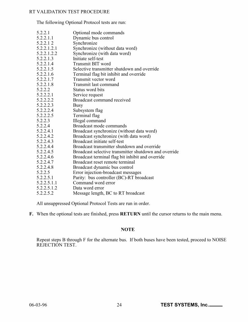
The following Optional Protocol tests are run:
5.2.2.1 Optional mode commands 5.2.2.1.1 Dynamic bus control 5.2.2.1 2 Synchronize 5.2.2.1.2.1 Synchronize (without data word) 5.2.2.1.2.2 Synchronize (with data word) 5.2.2.1.3 Initiate self-test 5.2.2.1.4 Transmit BIT word 5.2.2.1.5 Selective transmitter shutdown and override 5.2.2.1.6 Terminal flag bit inhibit and override 5.2.2.1.7 Transmit vector word 5.2.2.1.8 Transmit last command 5.2.2.2 Status word bits 5.2.2.2.1 Service request 5.2.2.2.2 Broadcast command received 5.2.2.2.3 Busy 5.2.2.2.4 Subsystem flag 5.2.2.2.5 Terminal flag 5.2.2.3 Illegal command 5.2.2.4 Broadcast mode commands 5.2.2.4.1 Broadcast synchronize (without data word)5.2.2.4.2 Broadcast synchronize (with data word)5.2.2.4.3 Broadcast initiate self-test5.2.2.4.4 Broadcast transmitter shutdown and override 5.2.2.4.5 Broadcast selective transmitter shutdown and override 5.2.2.4.6 Broadcast terminal flag bit inhibit and override 5.2.2.4.7 Broadcast reset remote terminal 5.2.2.4.8 Broadcast dynamic bus control 5.2.2.5 Error injection-broadcast messages 5.2.2.5.1 Parity: bus controller (BC)-RT broadcast5.2.2.5.1.1 Command word error 5.2.2.5.1.2 Data word error 5.2.2.5.2 Message length, BC to RT broadcast
All unsuppressed Optional Protocol Tests are run in order.
F. When the optional tests are finished, press RETURN until the cursor returns to the main menu.
NOTE
Repeat steps B through F for the alternate bus. If both buses have been tested, proceed to NOISEREJECTION TEST.

RT VALIDATION TEST PROCEDURE
06-03-96 25 TEST SYSTEMS, Inc.
VII. 5.3 NOISE REJECTION TEST
A. Connect the equipment as shown in Figure 13 or Figure 14 for the transformer coupled or directcoupled bus to be tested. See Figure 10A of the RT Validation Test Plan for the Noise RejectionTest Configuration. Note: The True RMS Voltmeter should be warmed up for one hour prior totesting.
1. Connect the bus connector on the 1553 NOISE GENERATOR CARD in the computer to theappropriately coupled long bus connector on the CONNECTION PANEL and the UUT input.
2. Connect the SCOPE and the True RMS Voltmeter to the UUT input. Use an isolation plug onthe True RMS Voltmeter.
N = 1553 NOISE GENERATOR CARD output.
Figure 13. Noise Rejection Transformer Coupled Configuration
Figure 14. Noise Rejection Direct Coupled Configuration

RT VALIDATION TEST PROCEDURE
06-03-96 26 TEST SYSTEMS, Inc.
B. Press F2. With the cursor on "Bus Selected", press the SPACE BAR to select the desired bus (A/B).
C. With the Noise off on the 1553 NOISE GENERATOR CARD, adjust the 1553 BUS TESTERamplitude to the test configuration.
1. Press F3 to enter the BC Amplitude Calibration menu.2. Move the cursor to "Protocol BC Transmit Amplitude 2.1 Vpp" for the data bus being tested.3. Press the + or - keys to increase or decrease the measured amplitude to 2.1 Vpp. The amplitude
is measured differentially at the bus input of the UUT with the oscilloscope.4. Press RETURN to exit this menu.5. Press F2 to return to the main menu.
D. Set the noise level on the 1553 NOISE GENERATOR CARD.
1. Press ALT-F10 to enter the Control Program. Press ALT-F9 to enter DOS. Enter NOISE (orNOISE/M for a monochrom monitor) and press RETURN to enter the 1553 NOISEGENERATOR CARD CONTROL PROGRAM.
2. Set the noise level to 140 mVrms for transformer coupling or 200 mVrms for direct couplingusing the True RMS Voltmeter. Note the value of the noise level reading on the screen. Removethe True RMS Voltmeter. The noise level reading on the screen will have changed so adjust thenoise level to the value noted.
3. Exit the 1553 NOISE GENERATOR CARD CONTROL PROGRAM. Press ALT-F10 to returnto the Validation Program.
E. Move the cursor to "5.3 Noise Rejection Tests".
F. Press TAB to select the first submenu. The prompts "Total Words Sent" and "Total Errors" appear.
G. With the cursor on "Total Words Sent", press F9 to start the Noise Rejection Test. This test takesapproximately 25 minutes if there are no errors.
H. When the Noise Rejection Test is finished, press RETURN until the cursor returns to the mainmenu.
I. Turn the noise off on the 1553 NOISE GENERATOR CARD.
NOTE
Repeat steps A through H for the alternate bus. If both buses have been tested, disconnect the 1553NOISE GENERATOR CARD and proceed to TEST TERMINATION.

RT VALIDATION TEST PROCEDURE
06-03-96 27 TEST SYSTEMS, Inc.
VIII. TEST TERMINATION
A. Add any pertinent comments concerning the testing to the Wordstar customer information textfile.
B. Incorporate the Wordstar customer information textfile into the Test Results File.
1. In the Validation Program, press F2 and type the customer information data file filename at theprompt "Cust. Info File:". Press RETURN.
2. Press F2 to return to the main menu.
C. Press CTRL-F2 and type E to exit the Validation Program.
D. Generate the Validation Report using the VALREPT program.
1. Type VALREPT at the prompt and press RETURN twice.
2. Enter the Test Results File filename on the first line and press RETURN.
3. Suppress a page or set of pages (containing a test or group of tests) that are not to be printed inthe report by placing the cursor on the appropriate line and pressing the SPACE BAR. Pagenumbers appear in parentheses next to the test section or subsection. An "S" indicates that allpages for a test or set of tests have been suppressed. An "s" indicates that one or more (but notall) pages for a test or set of tests have been suppressed.
4. Print the report to a disk file by pressing F1 and specifying the test report filename (i.e.Customer.RPT) at the prompt.
5. Press CTRL-F2 to exit.
E. Before printing the Validation Report on a printer, the report can be checked on the monitor usingthe VIEWREPT program.
1. On the MS DOS command line, specify the report filename when calling the VIEWREPTprogram. Type VIEWREPT filename.ext.
2. Type CTRL-F2 to exit the VIEWREPT program.
3. If changes need to be made in the report, modify the customer information textfile in Wordstarand repeat steps B through E.
F. Print the hard copy of the test report.