Test Solutions - Programming Manual Input / Output (IO ... · Test Solutions - Programming Manual...
64
Test Solutions - Programming Manual Input / Output (IO) Control Boxes USB Series USB Controlled Input / Output (IO) Control Boxes www.minicircuits.com | PO Box 350166, Brooklyn, NY 11235-0003 | +1 718-934-4500 | [email protected]
-
Upload
trinhxuyen -
Category
Documents
-
view
225 -
download
0
Transcript of Test Solutions - Programming Manual Input / Output (IO ... · Test Solutions - Programming Manual...

Test Solutions - Programming Manual
Input / Output (IO) Control Boxes
USB Series USB Controlled Input / Output (IO) Control Boxes
www.minicircuits.com | PO Box 350166, Brooklyn, NY 11235-0003 | +1 718-934-4500 | [email protected]

Important Notice This guide is owned by Mini-Circuits and is protected by copyright, trademark and other intellectual property laws. The information in this guide is provided by Mini-Circuits as an accommodation to our customers and may be used only to promote and accompany the purchase of Mini-Circuits’ Parts. This guide may not be reproduced, modified, distributed, published, stored in an electronic database, or transmitted and the information contained herein may not be exploited in any form or by any means, electronic, mechanical recording or otherwise, without prior written permission from Mini-Circuits. This guide is subject to change, qualifications, variations, adjustments or modifications without notice and may contain errors, omissions, inaccuracies, mistakes or deficiencies. Mini-Circuits assumes no responsibility for, and will have no liability on account of, any of the foregoing. Accordingly, this guide should be used as a guideline only. Trademarks Microsoft, Windows, Visual Basic, Visual C# and Visual C++ are registered trademarks of Microsoft Corporation. LabVIEW and CVI are registered trademarks of National Instruments Corporation. Delphi is a registered trademark of Delphi Technologies, Inc. MATLAB is a registered trademark of The MathWorks, Inc. Agilent VEE is a registered trademark of Agilent Technologies, Inc. Linux is a registered trademark of Linus Torvalds. Mac is a registered trademark of Apple Inc. Python is a registered trademark of Python Software Foundation Corporation. All other trademarks cited within this guide are the property of their respective owners. Neither Mini-Circuits nor the Mini-Circuits PTE (portable test equipment) series are affiliated with or endorsed or sponsored by the owners of the above referenced trademarks. Mini-Circuits and the Mini-Circuits logo are registered trademarks of Scientific Components Corporation. Mini-Circuits 13 Neptune Avenue Brooklyn, NY 11235, USA Phone: +1-718-934-4500 Email: [email protected] Web: www.minicircuits.com

Test Solutions - Programming Manual Page 3 Input / Output (IO) Control Boxes 3-Jan-18 (A2)
1 - Overview ................................................................................................... 5
2 - Operating in a Windows Environment via USB .......................................... 6
2.1 - The DLL (Dynamic Link Library) Concept ................................................................. 6 2.1 (a) - ActiveX COM Object .......................................................................................................... 7 2.1 (b) - Microsoft.NET Class Library .............................................................................................. 9
2.2 - Referencing the DLL (Dynamic Linked Library) ...................................................... 10 2.2 (a) - Example Declarations using the ActiveX DLL (MCL_USB_To_IO.dll) ............................... 10 2.2 (b) - Example Declarations using the .NET DLL (mcl_USB_To_IO_64.dll) ............................... 10
2.3 - Summary of DLL Functions ................................................................................... 11
2.4 - Description of DLL Functions ................................................................................ 12 2.4 (a) - Open Control Box Connection ......................................................................................... 12 2.4 (b) - Close Control Box Connection ......................................................................................... 13 2.4 (c) - Read Model Name of Control Box ................................................................................... 14 2.4 (d) - Read Serial Number of Control Box ................................................................................ 15 2.4 (e) - Get List of Connected Serial Numbers ............................................................................ 16 2.4 (f) - Set Byte A As Output ........................................................................................................ 17 2.4 (g) - Set Byte B As Output ....................................................................................................... 18 2.4 (h) - Set Byte A As Input .......................................................................................................... 19 2.4 (i) - Set Byte B As Input ........................................................................................................... 20 2.4 (j) - Set Byte A ......................................................................................................................... 21 2.4 (k) - Set Byte B......................................................................................................................... 22 2.4 (l) - Read Byte ......................................................................................................................... 23 2.4 (m) - Read Byte A .................................................................................................................... 25 2.4 (n) - Read Byte B ..................................................................................................................... 26 2.4 (o) - Set TTL Bit ........................................................................................................................ 27 2.4 (p) - Set TTL Pulse.................................................................................................................... 28 2.4 (q) - Get TTL Bit ....................................................................................................................... 29 2.4 (r) - Set SPI Pulse Width .......................................................................................................... 30 2.4 (s) - Send SPI Data ................................................................................................................... 31 2.4 (t) - Send SPI Data with Trigger Out ........................................................................................ 32 2.4 (u) - Set Individual Relay ......................................................................................................... 33 2.4 (v) - Set All Relays.................................................................................................................... 34 2.4 (w) - Read Relay States ........................................................................................................... 36 2.4 (x) - Get Firmware ................................................................................................................... 38
3 - Operating in a Linux Environment ............................................................ 39
3.1 - Summary of Commands ....................................................................................... 39
3.2 - Detailed Description of Commands ...................................................................... 40 3.2 (a) - Get Device Model Name ................................................................................................. 40 3.2 (b) - Get Device Serial Number ............................................................................................... 41 3.2 (c) - Get Status of Relays ......................................................................................................... 42 3.2 (d) - Set Single Relay ............................................................................................................... 44 3.2 (e) - Set All Relays ................................................................................................................... 45 3.2 (f) - Set Single TTL Bit .............................................................................................................. 47 3.2 (g) - Get Single TTL Bit ............................................................................................................. 49 3.2 (h) - Set TTL Byte ..................................................................................................................... 51 3.2 (i) - Get TTL Byte ..................................................................................................................... 53 3.2 (j) - Set Byte A As Input ........................................................................................................... 55 3.2 (k) - Set Byte B As Input .......................................................................................................... 56 3.2 (l) - Set Byte A As Output ........................................................................................................ 57

Test Solutions - Programming Manual Page 4 Input / Output (IO) Control Boxes 3-Jan-18 (A2)
3.2 (m) - Set Byte B As Output ...................................................................................................... 58 3.2 (n) - Send SPI Output .............................................................................................................. 59 3.2 (o) - Send SPI Output with Trigger .......................................................................................... 61 3.2 (p) - Set SPI Pulse Width ......................................................................................................... 63 3.2 (q) - Get Firmware .................................................................................................................. 64

Test Solutions - Programming Manual Page 5 Input / Output (IO) Control Boxes 3-Jan-18 (A2)
1 - Overview
This programming manual is intended for customers wishing to create their own interface for Mini-Circuits' USB controlled, input / output control boxes. Mini-Circuits offers support over a variety of operating systems, programming environments and third party applications. Support for Windows® operating systems is provided through the Microsoft®.NET® and ActiveX® frameworks to allow the user to develop customized control applications. Support for Linux® operating systems is accomplished using the standard libhid and libusb libraries. Mini-Circuits has experience with a wide variety of environments including (but not limited to):
Visual Basic®, Visual C#®, Visual C++®
Delphi®
Borland C++®
CVI®
LabVIEW®
MATLAB®
Python®
Agilent VEE® The IO control box software package includes a GUI program, ActiveX and .NET DLL files, Linux support, project examples for third party software, and detailed user manuals. The latest package is available for download at: https://www.minicircuits.com/softwaredownload/usbio.html For details on individual models, application notes, GUI installation instructions and user guides please see: https://www.minicircuits.com/WebStore/PortableTestEquipment.html Files made available for download from the Mini-Circuits website are subject to Mini-Circuits’ terms of use which are available on the website.

Test Solutions - Programming Manual Page 6 Input / Output (IO) Control Boxes 3-Jan-18 (A2)
2 - Operating in a Windows Environment via USB
When connected by USB, the computer will recognize the control box as a Human Interface Device (HID). The ActiveX and .NET DLL files provide the method of control.
2.1 - The DLL (Dynamic Link Library) Concept
The Dynamic Link Library concept is Microsoft's implementation of the shared library concept in the Windows environment. DLLs provide a mechanism for shared code and data, intended to allow a developer to distribute applications without requiring code to be re-linked or recompiled. Mini-Circuits' software package provides DLL Objects designed to allow your own software application to interface with the functions of the IO control box.
The software package provides two DLL files, the choice of which file to use is dictated by the user’s operating system:
1. ActiveX com object
Designed to be used in any programming environment that supports third party ActiveX COM (Component Object Model) compliant applications. The ActiveX file should be registered using RegSvr32 (see following sections for details).
2. Microsoft.NET Class Library
A logical unit of functionality that runs under the control of the Microsoft.NET system.
User’s Software Application (3rd party software such as LabVIEW, Delphi, Visual C++,
Visual C#, Visual Basic, and Microsoft.Net)
DLL (Dynamic Link Libraries)
Mini-Circuits’ USB Portable Test Equipment
Fig 2.1-a: DLL Interface Concept

Test Solutions - Programming Manual Page 7 Input / Output (IO) Control Boxes 3-Jan-18 (A2)
2.1 (a) - ActiveX COM Object
ActiveX COM object DLL files are designed to be used with both 32-bit and 64-bit Windows operating systems. A 32-bit programming environment that is compatible with ActiveX is required. To develop 64-bit applications, the Microsoft.NET Class library should be used instead.
Supported Programming Environments
Mini-Circuits’ IO control boxes have been tested in the following programming environments. This is not an exhaustive list and the DLL file is designed to operate in most environments that support ActiveX functionality. Please contact Mini-Circuits for support.
Visual Studio® 6 (Visual C++ and Visual Basic)
LabVIEW 8.0 or newer
MATLAB 7 or newer
Delphi
Borland C++
Agilent VEE
Python Installation
1. Copy the DLL file (mcl_USB_To_IO.dll) to the correct directory: For 32-bit Windows operating systems this is C:\WINDOWS\System32 For 64-bit Windows operating systems this is C:\WINDOWS\SysWOW64
2. Open the Command Prompt: a. For Windows XP® (see Fig 2.1-b):
i. Select “All Programs” and then “Accessories” from the Start Menu ii. Click on “Command Prompt” to open
b. For later versions of the Windows operating system you will need to have Administrator privileges in order to run the Command Prompt in “Elevated” mode (see Fig 2.1-c for Windows 7, 8 and 10):
i. Open the Start Menu/Start Screen and type “Command Prompt” ii. Right-click on the shortcut for the Command Prompt
iii. Select “Run as Administrator” iv. You may be prompted to enter the log in details for an Administrator
account if the current user does not have Administrator privileges on the local PC
3. Use regsvr32 to register the DLL: For 32-bit Windows operating systems type (see Fig 2.1-d):
\WINDOWS\System32\Regsvr32 \WINDOWS\System32\ mcl_USB_To_IO.dll For 64-bit Windows operating systems type (see Fig 2.1-e):
\WINDOWS\SysWOW64\Regsvr32 \WINDOWS\SysWOW64\ mcl_USB_To_IO.dll 4. Hit enter to confirm and a message box will appear to advise of successful registration.

Test Solutions - Programming Manual Page 8 Input / Output (IO) Control Boxes 3-Jan-18 (A2)
Fig 2.1-b: Opening the Command Prompt in Windows XP
Fig 2.1-c: Opening the Command Prompt in Windows 7 (left), Windows 8 (middle) and Windows 10 (right)
Fig 2.1-d: Registering the DLL in a 32-bit environment
Fig 2.1-e: Registering the DLL in a 64-bit environment

Test Solutions - Programming Manual Page 9 Input / Output (IO) Control Boxes 3-Jan-18 (A2)
2.1 (b) - Microsoft.NET Class Library
Microsoft.NET class libraries are designed to be used with both 32-bit and 64-bit Windows operating systems. To develop 64-bit applications the user must have both a 64-bit operating system and 64-bit programming environment. However, the Microsoft.NET class library is also compatible with 32-bit programming environments.
Supported Programming Environments
Mini-Circuits’ IO control boxes have been tested in the following programming environments. This is not an exhaustive list and the DLL file is designed to operate in most environments that support Microsoft.NET functionality. Please contact Mini-Circuits for support.
National Instruments CVI
Microsoft.NET (Visual C++, Visual Basic.NET, Visual C# 2003 or newer)
LabVIEW 2009 or newer
MATLAB 2008 or newer
Delphi
Borland C++ Installation
1. Copy the DLL file (mcl_rudat64.dll) to the correct directory a. For 32 bit Windows operating systems this is C:\WINDOWS\System32 b. For 64 bit Windows operating systems this is C:\WINDOWS\SysWOW64
2. No registration is required

Test Solutions - Programming Manual Page 10 Input / Output (IO) Control Boxes 3-Jan-18 (A2)
2.2 - Referencing the DLL (Dynamic Linked Library) The DLL file is installed in the host PC’s system folders using the steps outlined above. Most programming environments will require a reference to be set to the DLL. Within the program, a new instance of the DLL's USB control class can be created for each IO box to control. The details of this vary between programming environments and languages but Mini-Circuits can provide detailed support on request. In the following examples, MyPTE1 and MyPTE2 will be used as names of 2 declared control box objects.
2.2 (a) - Example Declarations using the ActiveX DLL (MCL_USB_To_IO.dll)
2.2 (b) - Example Declarations using the .NET DLL (mcl_USB_To_IO_64.dll)
Visual Basic Public MyPTE1 As New MCL_USB_To_IO.USB_IO
' Initialize new control box object, assign to MyPTE1
Public MyPTE2 As New MCL_USB_To_IO.USB_IO
' Initialize new control box object, assign to MyPTE1
Visual C++ MCL_USB_To_IO::USB_IO ^MyPTE1 = gcnew MCL_USB_To_IO::USB_IO();
// Initialize new control box instance, assign to MyPTE1
MCL_USB_To_IO::USB_IO ^MyPTE2 = gcnew MCL_USB_To_IO::USB_IO();
// Initialize new control box instance, assign to MyPTE2 Visual C#
MCL_USB_To_IO.USB_IO MyPTE1 = new MCL_USB_To_IO.USB_IO();
// Initialize new control box instance, assign to MyPTE1
MCL_USB_To_IO.USB_IO MyPTE2 = new MCL_USB_To_IO.USB_IO();
// Initialize new control box instance, assign to MyPTE2
Matlab MyPTE1 = actxserver('MCL_USB_To_IO.USB_IO')
% Initialize new control box instance, assign to MyPTE1
MyPTE2 = actxserver('MCL_USB_To_IO.USB_IO')
% Initialize new control box instance, assign to MyPTE2
Visual Basic
Public MyPTE1 As New mcl_USB_To_IO_64.USB_IO
' Initialize new control box object, assign to MyPTE1
Public MyPTE2 As New mcl_USB_To_IO_64.USB_IO
' Initialize new control box object, assign to MyPTE1
Visual C++
mcl_USB_To_IO_64::USB_IO ^MyPTE1 = gcnew mcl_USB_To_IO_64::USB_IO();
// Initialize new control box instance, assign to MyPTE1
mcl_USB_To_IO_64::USB_IO ^MyPTE2 = gcnew mcl_USB_To_IO_64::USB_IO();
// Initialize new control box instance, assign to MyPTE2
Visual C#
mcl_USB_To_IO_64.USB_IO MyPTE1 = new mcl_USB_To_IO_64.USB_IO();
// Initialize new control box instance, assign to MyPTE1
mcl_USB_To_IO_64.USB_IO MyPTE2 = new mcl_USB_To_IO_64.USB_IO();
// Initialize new control box instance, assign to MyPTE2
Matlab
MCL_ATT=NET.addAssembly('C:\Windows\SysWOW64\ mcl_USB_To_IO_64.dll')
MyPTE1=mcl_USB_To_IO_64.USB_IO % Initialize new control box instance
MyPTE2=mcl_USB_To_IO_64.USB_IO % Initialize new control box instance

Test Solutions - Programming Manual Page 11 Input / Output (IO) Control Boxes 3-Jan-18 (A2)
2.3 - Summary of DLL Functions
The following functions are defined in both of the DLL files. Please see the following sections for a full description of their structure and implementation.
a) Short Connect (Optional String SN) b) Void Disconnect () c) Short Read_ModelName (String ModelName) d) Short Read_SN (String SN) e) Short Get_Available_SN_List (String SN_List) f) Short Set_ByteA_As_Output () g) Short Set_ByteB_As_Output () h) Short Set_ByteA_As_Input () i) Short Set_ByteB_As_Input () j) Short Set_ByteA (Byte Val) k) Short Set_ByteB (Byte Val) l) Short ReadByte (String ByteName, Byte Ret_ByteVal) m) Short ReadByteA (Byte Ret_ByteVal) n) Short ReadByteB (Byte Ret_ByteVal) o) Short Set_TTLBit (String BitName, Short BitVal) p) Short Set_TTLPulse (String BitName, Short ms) q) Short ReadBit (String BitRequest, Byte Ret_BitVal) r) Short Set_SPI_PulseWidth (Short PulsWidth) s) Short SPI_OUT (String ClockBit, String DataBit, String LEBit, String RegData) t) Short SPI_OUT_Trigg (String RegData, Short Trigger) u) Short Set_Relay (Short RelayNo, Short On_OFF) v) Short Set_RelayByte (Byte val) w) Short Read_Relays_Byte (Byte RetVal) x) Short GetExtFirmware (Short A0, Short A1, Short A2, String Firmware)

Test Solutions - Programming Manual Page 12 Input / Output (IO) Control Boxes 3-Jan-18 (A2)
2.4 - Description of DLL Functions
2.4 (a) - Open Control Box Connection
Declaration Short Connect(Optional String SN)
Description
This function is called to initialize the connection to a USB control box. If multiple control boxes are connected to the same computer, then the serial number should be included, otherwise this can be omitted. The connection process can take a few milliseconds so it is recommended that the connection be made once at the beginning of the routine and left open until the control box is no longer needed. The control box should be disconnected on completion of the program using the Disconnect function.
Parameters
Data Type Variable Description
String SN Optional. A string containing the serial number of the USB control box. Can be omitted if only one control box is connected but must be included otherwise.
Return Values
Data Type Value Description
Short 0 No connection was possible
1 Connection successfully established
2 Device already connected
3 Requested serial number is not available
Examples
See Also Close Control Box Connection Get List of Connected Serial Numbers
Visual Basic status = MyPTE1.Connect(SN)
Visual C++ status = MyPTE1->Connect(SN);
Visual C# status = MyPTE1.Connect(SN);
Matlab status = MyPTE1.Connect(SN)

Test Solutions - Programming Manual Page 13 Input / Output (IO) Control Boxes 3-Jan-18 (A2)
2.4 (b) - Close Control Box Connection
Declaration Void Disconnect()
Description
This function is called to close the connection to the control box. It is strongly recommended that this function is used prior to ending the program. Failure to do so may result in a connection problem with the device. Should this occur, shut down the program and unplug the control box from the computer, then reconnect the control box before attempting to start again.
Parameters
Data Type Variable Description
None
Return Values
Data Type Value Description
None
Examples
See Also Open Control Box Connection
Visual Basic MyPTE1.Disconnect()
Visual C++ MyPTE1->Disconnect();
Visual C# MyPTE1.Disconnect();
Matlab MyPTE1.Disconnect

Test Solutions - Programming Manual Page 14 Input / Output (IO) Control Boxes 3-Jan-18 (A2)
2.4 (c) - Read Model Name of Control Box
Declaration Short Read_ModelName(String ModelName)
Description
This function is called to determine the Mini-Circuits part number of the connected control box.
Parameters
Data Type Variable Description
String ModelName Required. User defined variable which will be updated with the Mini-Circuits part number.
Return Values
Data Type Value Description
Short 0 Command failed
Non zero Command completed successfully
Examples
See Also Read Serial Number of Control Box
Visual Basic If MyPTE1.Read_ModelName(ModelName) > 0 Then
MsgBox ("The connected model is " & ModelName)
' Display a message stating the model name
End If Visual C++
if (MyPTE1->Read_ModelName(ModelName) > 0 )
{
MessageBox::Show("The connected model is " , ModelName);
// Display a message stating the model name
} Visual C#
if (MyPTE1.Read_ModelName(ref(ModelName)) > 0 )
{
MessageBox.Show("The connected model is ", ModelName);
// Display a message stating the model name
} Matlab
[status, ModelName] = MyPTE1.Read_ModelName(ModelName)
if status > 0
h = msgbox('The connected model is ', ModelName)
% Display a message stating the model name
end

Test Solutions - Programming Manual Page 15 Input / Output (IO) Control Boxes 3-Jan-18 (A2)
2.4 (d) - Read Serial Number of Control Box
Declaration Short Read_SN(String SN)
Description
This function is called to determine the Mini-Circuits serial number of the connected control box.
Parameters
Data Type Variable Description
String SN Required. User defined variable which will be updated with the device serial number.
Return Values
Data Type Value Description
Short 0 Command failed
Non zero Command completed successfully
Examples
See Also Read Model Name of Control Box
Visual Basic If MyPTE1.Read_SN(SN) > 0 Then
MsgBox ("The connected model is " & SN)
'Display a message stating the serial number
End If Visual C++
if (MyPTE1->Read_SN(SN) > 0 )
{
MessageBox::Show("The connected model is " + SN);
// Display a message stating the serial number
} Visual C#
if (MyPTE1.Read_SN(ref(SN)) > 0 )
{
MessageBox.Show("The connected model is " + SN);
// Display a message stating the serial number
} Matlab
[status, SN] = MyPTE1.Read_SN(SN)
if status > 0
h = msgbox('The connected switch is ', SN)
% Display a message stating the serial number
end

Test Solutions - Programming Manual Page 16 Input / Output (IO) Control Boxes 3-Jan-18 (A2)
2.4 (e) - Get List of Connected Serial Numbers
Declaration Short Get_Available_SN_List(String SN_List)
Description
This function takes a user defined variable and updates it with a list of serial numbers for all available (currently connected) control boxes.
Parameters
Data Type Variable Description
String SN_List Required. User defined variable which will be updated with a list of all connected serial numbers, separated by a single space character, for example “11110001 11110002 11110003”.
Return Values
Data Type Value Description
Short 0 Command failed
Short 1 Command completed successfully
Examples
See Also Read Serial Number of Control Box
Visual Basic If MyPTE1.Get_Available_SN_List(SN_List) > 0 Then
array_SN() = Split(SN_List, " ")
' Split the list into an array of serial numbers
For i As Integer = 0 To array_SN.Length - 1
' Loop through the array and use each serial number
Next
End If Visual C++
if (MyPTE1 ->Get_Available_SN_List(SN_List) > 0)
{
// split the List into array of SN's
} Visual C#
if (MyPTE1.Get_Available_SN_List(ref(SN_List)) > 0)
{
// split the List into array of SN's
} Matlab
[status, SN_List] = MyPTE1.Get_Available_SN_List(SN_List)
if status > 0
% split the List into array of SN's
end
Test Solutions - Programming Manual Page 17 Input / Output (IO) Control Boxes 3-Jan-18 (A2)
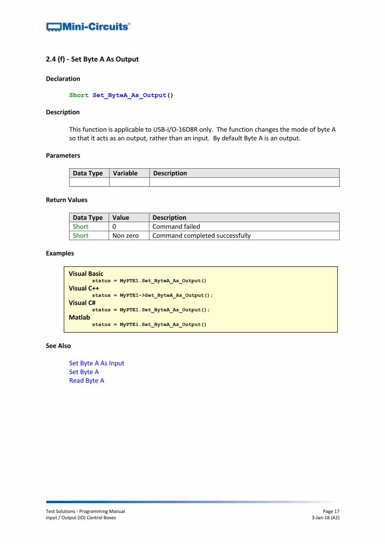
2.4 (f) - Set Byte A As Output
Declaration Short Set_ByteA_As_Output()
Description
This function is applicable to USB-I/O-16D8R only. The function changes the mode of byte A so that it acts as an output, rather than an input. By default Byte A is an output.
Parameters
Data Type Variable Description
Return Values
Data Type Value Description
Short 0 Command failed
Short Non zero Command completed successfully
Examples
See Also Set Byte A As Input Set Byte A Read Byte A
Visual Basic status = MyPTE1.Set_ByteA_As_Output()
Visual C++ status = MyPTE1->Set_ByteA_As_Output();
Visual C# status = MyPTE1.Set_ByteA_As_Output();
Matlab status = MyPTE1.Set_ByteA_As_Output()

Test Solutions - Programming Manual Page 18 Input / Output (IO) Control Boxes 3-Jan-18 (A2)
2.4 (g) - Set Byte B As Output
Declaration Short Set_ByteB_As_Output()
Description
This function is not available for USB-I/O-4D2R. The function changes the mode of byte B so that it acts as an output, rather than an input. By default Byte B is an output.
Parameters
Data Type Variable Description
Return Values
Data Type Value Description
Short 0 Command failed
Short Non zero Command completed successfully
Examples
See Also Set Byte B As Input Set Byte B Read Byte B
Visual Basic status = MyPTE1.Set_ByteB_As_Output()
Visual C++ status = MyPTE1->Set_ByteB_As_Output();
Visual C# status = MyPTE1.Set_ByteB_As_Output();
Matlab status = MyPTE1.Set_ByteB_As_Output()

Test Solutions - Programming Manual Page 19 Input / Output (IO) Control Boxes 3-Jan-18 (A2)
2.4 (h) - Set Byte A As Input
Declaration Short Set_ByteA_As_Input()
Description
This function is applicable to USB-I/O-16D8R only. The function changes the mode of byte A so that it acts as an input, rather than an output. By default Byte A is an output.
Parameters
Data Type Variable Description
Return Values
Data Type Value Description
Short 0 Command failed
Short Non zero Command completed successfully
Examples
See Also Set Byte A As Output Set Byte A Read Byte A
Visual Basic status = MyPTE1.Set_ByteA_As_Input()
Visual C++ status = MyPTE1->Set_ByteA_As_Input();
Visual C# status = MyPTE1.Set_ByteA_As_Input();
Matlab status = MyPTE1.Set_ByteA_As_Input()

Test Solutions - Programming Manual Page 20 Input / Output (IO) Control Boxes 3-Jan-18 (A2)
2.4 (i) - Set Byte B As Input
Declaration Short Set_ByteB_As_Input()
Description
This function is not available for USB-I/O-4D2R. The function changes the mode of byte B so that it acts as an input, rather than an output. By default Byte B is an output.
Parameters
Data Type Variable Description
Return Values
Data Type Value Description
Short 0 Command failed
Short Non zero Command completed successfully
Examples
See Also Set Byte B As Output Set Byte B Read Byte B
Visual Basic status = MyPTE1.Set_ByteB_As_Input()
Visual C++ status = MyPTE1->Set_ByteB_As_Input();
Visual C# status = MyPTE1.Set_ByteB_As_Input();
Matlab status = MyPTE1.Set_ByteB_As_Input()

Test Solutions - Programming Manual Page 21 Input / Output (IO) Control Boxes 3-Jan-18 (A2)
2.4 (j) - Set Byte A
Declaration Short Set_ByteA(Byte Val)
Description
This function is applicable to USB-I/O-16D8R only. The function sets the state of output byte A so that each bit is logic “low” (0) or logic “high” (1). Byte A is made up of 8 output bits, A0 to A7. Note: Byte A must be set to output mode rather than input mode in order to use this function (see Set_ByteA_As_Output).
Parameters
Data Type Variable Description
Byte Val Required. A byte indicating the state to which each bit should be set, with bit 7 as the MSB and bit 0 as the LSB. For example to set output bits A2, A4 and A5 to logic high, with all others to logic low: A7=0, A6=0, A5=1, A4=1, A3=0, A2=1, A1=0, A0=0 Val = 00110100 (binary) = 52 (decimal)
Return Values
Data Type Value Description
Short 0 Command failed
Short Non zero Command completed successfully
Examples
See Also Set Byte A As Output Set Byte A As Input Read Byte A
Visual Basic status = MyPTE1.Set_ByteA(Val)
Visual C++ status = MyPTE1->Set_ByteA(Val);
Visual C# status = MyPTE1.Set_ByteA(Val);
Matlab [status, Val] = MyPTE1.Set_ByteA(Val)

Test Solutions - Programming Manual Page 22 Input / Output (IO) Control Boxes 3-Jan-18 (A2)
2.4 (k) - Set Byte B
Declaration Short Set_ByteB(Byte Val)
Description
This function sets the state of output byte B so that each bit is logic “low” (0) or logic “high” (1). Byte B is made up of 8 output bits, B0 to B7. Notes:
1. For models other than USB-I/O-4D2R, byte B must be set to output mode rather than input mode in order to use this function (see Set_ByteB_As_Output)
2. For USB-I/O-4D2R, only bits B0 to B3 are available, bits B4 to B7 are "don't care” and can be any value
Parameters
Data Type Variable Description
Byte Val Required. A byte indicating the state to which each bit should be set, with bit 7 as the MSB and bit 0 as the LSB. For example to set output bits B2, B4 and B5 to logic high, with all others to logic low: B7=0, B6=0, B5=1, B4=1, B3=0, B2=1, B1=0, B0=0 Val = 00110100 (binary) = 52 (decimal)
Return Values
Data Type Value Description
Short 0 Command failed
Short Non zero Command completed successfully
Examples
See Also Set Byte B As Output Set Byte B As Input Read Byte B
Visual Basic status = MyPTE1.Set_ByteB(Val)
Visual C++ status = MyPTE1->Set_ByteB(Val);
Visual C# status = MyPTE1.Set_ByteB(Val);
Matlab [status, Val] = MyPTE1.Set_ByteB(Val)

Test Solutions - Programming Manual Page 23 Input / Output (IO) Control Boxes 3-Jan-18 (A2)
2.4 (l) - Read Byte
Declaration Short ReadByte(String ByteName, Byte Ret_ByteVal)
Description
This function is not available for USB-I/O-4D2R. This function reads the state of the specified input (byte A or byte B). Each byte is made up of 8 input bits, 0 to 7, which could be at logic “low” (0) or logic “high” (1).
Parameters
Data Type Variable Description
String ByteName Required. The byte to read, either “A” or “B”.
Byte Ret_ByteVal Required. A user defined variable which will be updated with the state of each bit the specified byte. Bit 7 is the MSB and bit 0 is the LSB. For example, if the function returns: Ret_ByteVal = 106 (decimal) = 01101010 (binary) Then: bit 7=0, bit 6=1, bit 5=1, bit 4=0, bit 3=1, bit 2=0, bit 1=1, bit 0=0
Return Values
Data Type Value Description
Short 0 Command failed
Short Non zero Command completed successfully
Examples
See Also Set Byte A As Output Set Byte A As Input Set Byte A
Read Byte A Read Byte B
Visual Basic Status = MyPTE1.ReadByte("A", Ret_ByteVal)
Visual C++ Status = MyPTE1->ReadByte("A", Ret_ByteVal);
Visual C# Status = MyPTE1.ReadByte("A", Ret_ByteVal);
Matlab [Status, ~, Ret_ByteVal] = MyPTE1.ReadByte('A', Ret_ByteVal)

Test Solutions - Programming Manual Page 24 Input / Output (IO) Control Boxes 3-Jan-18 (A2)

Test Solutions - Programming Manual Page 25 Input / Output (IO) Control Boxes 3-Jan-18 (A2)
2.4 (m) - Read Byte A
Declaration Short ReadByteA(Byte Ret_ByteVal)
Description
This function is not available for USB-I/O-4D2R. This function reads the state of the byte A input. Byte A is made up of 8 input bits, A0 to A7, which could be at logic “low” (0) or logic “high” (1).
Parameters
Data Type Variable Description
Byte Ret_ByteVal Required. A user defined byte which will be updated with the state of each bit in byte A. Bit 7 is the MSB and bit 0 is the LSB. For example, if the function sets: Ret_ByteVal = 106 (decimal) = 01101010 (binary) Then: A7=0, A6=1, A5=1, A4=0, A3=1, A2=0, A1=1, A0=0
Return Values
Data Type Value Description
Short 0 Command failed
Short Non zero Command completed successfully
Examples
See Also Set Byte A As Output Set Byte A As Input Set Byte A
Read Byte Read Byte B
Visual Basic Status = MyPTE1.ReadByteA(Ret_ByteVal)
Visual C++ Status = MyPTE1->ReadByteA(Ret_ByteVal);
Visual C# Status = MyPTE1.ReadByteA(Ret_ByteVal);
Matlab [Status, Ret_ByteVal] = MyPTE1.ReadByteA(Ret_ByteVal)

Test Solutions - Programming Manual Page 26 Input / Output (IO) Control Boxes 3-Jan-18 (A2)
2.4 (n) - Read Byte B
Declaration Short ReadByteB(Byte Ret_ByteVal)
Description
This function is not available for USB-I/O-4D2R. This function reads the state of the byte B input. Byte A is made up of 8 input bits, B0 to B7, which could be at logic “low” (0) or logic “high” (1).
Parameters
Data Type Variable Description
Byte Ret_ByteVal Required. A user defined byte which will be updated with the state of each bit in byte B. Bit 7 is the MSB and bit 0 is the LSB. For example, if the function sets: Ret_ByteVal = 106 (decimal) = 01101010 (binary) Then: A7=0, A6=1, A5=1, A4=0, A3=1, A2=0, A1=1, A0=0
Return Values
Data Type Value Description
Short 0 Command failed
Short Non zero Command completed successfully
Examples
See Also
Set Byte B As Output Set Byte B As Input Set Byte B Read Byte Read Byte A
Visual Basic Status = MyPTE1.ReadByteB(Ret_ByteVal)
Visual C++ Status = MyPTE1->ReadByteB(Ret_ByteVal);
Visual C# Status = MyPTE1.ReadByteB(Ret_ByteVal);
Matlab [Status, Ret_ByteVal] = MyPTE1.ReadByteB(Ret_ByteVal)

Test Solutions - Programming Manual Page 27 Input / Output (IO) Control Boxes 3-Jan-18 (A2)
2.4 (o) - Set TTL Bit
Declaration Short Set_TTLBit(String BitName, Short BitVal)
Description
This function sets the state of a single output bit specified by the user. Bits A0 to A7 and B0 to B7 can be set (model dependent). The value of each bit can be set to logic “low” (0) or logic “high” (1). Note: The relevant byte must be set to output mode rather than input mode in order to use this function (see Set_ByteA_As_Output and Set_ByteB_As_Output).
Parameters
Data Type Variable Description
String BitName Required. A string to indicate which bit is to be set, from “A0” to “A7”, or “B0” to “B7” (model dependent).
Short BitVal Required. An integer indicating the state to which the bit should be set, 0 or 1.
Return Values
Data Type Value Description
Short 0 Command failed
Short Non zero Command completed successfully
Examples
See Also
Set TTL Pulse Get TTL Bit
Visual Basic Status = MyPTE1.Set_TTLBit(BitName, BitVal)
Visual C++ Status = MyPTE1->Set_TTLBit(BitName, BitVal);
Visual C# Status = MyPTE1.Set_TTLBit(BitName, BitVal);
Matlab Status = MyPTE1.Set_TTLBit(BitName, BitVal)

Test Solutions - Programming Manual Page 28 Input / Output (IO) Control Boxes 3-Jan-18 (A2)
2.4 (p) - Set TTL Pulse
Declaration Short Set_TTLPulse(String BitName, Short ms)
Description
This function outputs a positive pulse from a single bit specified by the user. The specified bit will be set to logic high for a user specified time and then drop to logic low. Bits A0 to A7 and B0 to B7 can be pulsed (model dependent). If the selected bit was already at logic high it will remain so for the specified time and then drop to logic low. Note: The relevant byte must be set to output mode rather than input mode in order to use this function (see Set_ByteA_As_Output and Set_ByteB_As_Output).
Parameters
Data Type Variable Description
String BitName Required. A string to indicate which bit is to be pulsed, from “A0” to “A7”, or “B0” to “B7” (model dependent).
Short ms Required. The time in ms for which the specified bit should be held high, integer values from 1 to 255.
Return Values
Data Type Value Description
Short 0 Command failed
Short Non zero Command completed successfully
Examples
See Also Set TTL Bit Get TTL Bit
Visual Basic Status = MyPTE1.Set_TTLPulse(BitName, Ms)
Visual C++ Status = MyPTE1->Set_TTLPulse(BitName, Ms);
Visual C# Status = MyPTE1.Set_TTLPulse(BitName, Ms);
Matlab Status = MyPTE1.Set_TTLPulse(BitName, Ms)

Test Solutions - Programming Manual Page 29 Input / Output (IO) Control Boxes 3-Jan-18 (A2)
2.4 (q) - Get TTL Bit
Declaration Short ReadBit(String BitRequest, Byte Ret_BitVal)
Description
This function is not available for USB-I/O-4D2R. The function reads the state of a single bit specified by the user. Bits A0 to A7 and B0 to B7 can be requested (model dependent). The value of each bit could be logic “low” (0) or logic “high” (1).
Parameters
Data Type Variable Description
String BitRequest Required. A string to indicate which bit is to be read, from “A0” to “A7”, or “B0” to “B7”.
Byte Ret_ByteVal Required. A user defined byte which will be updated with the state of the requested bit.
Return Values
Data Type Value Description
Short 0 Command failed
Short Non zero Command completed successfully
Examples
See Also Set TTL Bit Set TTL Pulse
Visual Basic Status = MyPTE1.ReadBit(BitRequest, Ret_ByteVal)
Visual C++ Status = MyPTE1->ReadBit(BitRequest, Ret_ByteVal);
Visual C# Status = MyPTE1.ReadBit(BitRequest, Ret_ByteVal);
Matlab [Status, ~, Ret_ByteVal] = MyPTE1.ReadBit(BitRequest, Ret_ByteVal)

Test Solutions - Programming Manual Page 30 Input / Output (IO) Control Boxes 3-Jan-18 (A2)
2.4 (r) - Set SPI Pulse Width
Declaration Short Set_SPI_PulseWidth(Short PulsWidth)
Description
This function sets the pulse width that will be used for the Clock, Data and LE (Latch Enable) connections when the control box is used for SPI (Serial Peripheral Interface) communication. The pulse width can be set as any integer value from 0 to 255μs although in practice the minimum pulse width will be approximately 0.08μs. Note: The duty cycle remains constant at 50% so clock frequency will change as pulse width is varied.
Parameters
Data Type Variable Description
Short PulsWidth Required. An integer value from 0 to 255 to set the desired pulse width in μs
Return Values
Data Type Value Description
Short 0 Command failed
Short Non zero Command completed successfully
Examples
See Also Send SPI Data Send SPI Data With Trigger Out
Visual Basic Status = MyPTE1.Set_SPI_PulseWidth(PulseWidth)
Visual C++ Status = MyPTE1->Set_SPI_PulseWidth(PulseWidth);
Visual C# Status = MyPTE1.Set_SPI_PulseWidth(PulseWidth);
Matlab Status = MyPTE1.Set_SPI_PulseWidth(PulseWidth)

Test Solutions - Programming Manual Page 31 Input / Output (IO) Control Boxes 3-Jan-18 (A2)
2.4 (s) - Send SPI Data
Declaration Short SPI_Out(String ClockBit, String DataBit, String LEBit, String
_ RegData)
Description
This function sends SPI (Serial Peripheral Interface) data. The Clock bit, Data bit and LE (Latch Enable) bits to be used are defined by the user. The user specified binary data will be sent along with all required start, stop and parity bits (as required by the SPI communication protocol). Note: The relevant byte must be set to output mode rather than input mode in order to use this function (see Set_ByteA_As_Output and Set_ByteB_As_Output).
Parameters
Data Type Variable Description
String ClockBit Required. A string to define which bit to use as the Clock bit. Bits “A0” to “A7” and “B0” to “B7” (model dependent) can be selected.
String DataBit Required. A string to define which bit to use as the Data bit. Bits “A0” to “A7” and “B0” to “B7” (model dependent) can be selected.
String LEBit Required. A string to define which bit to use as the LE bit. Bits “A0” to “A7” and “B0” to “B7” (model dependent) can be selected.
String RegData Required. A binary string of up to 48 characters representing the data to be sent, for example “0011010101”.
Return Values
Data Type Value Description
Short 0 Command failed
Short Non zero Command completed successfully
Examples
See Also Set SPI Pulse Width Send SPI Data With Trigger Out
Visual Basic Status = MyPTE1.SPI_OUT(ClockBit, DataBit, LEBit, RegData)
Visual C++ Status = MyPTE1->SPI_OUT(ClockBit, DataBit, LEBit, RegData);
Visual C# Status = MyPTE1.SPI_OUT(ClockBit, DataBit, LEBit, RegData);
Matlab Status = MyPTE1.SPI_OUT(ClockBit, DataBit, LEBit, RegData)
Test Solutions - Programming Manual Page 32 Input / Output (IO) Control Boxes 3-Jan-18 (A2)
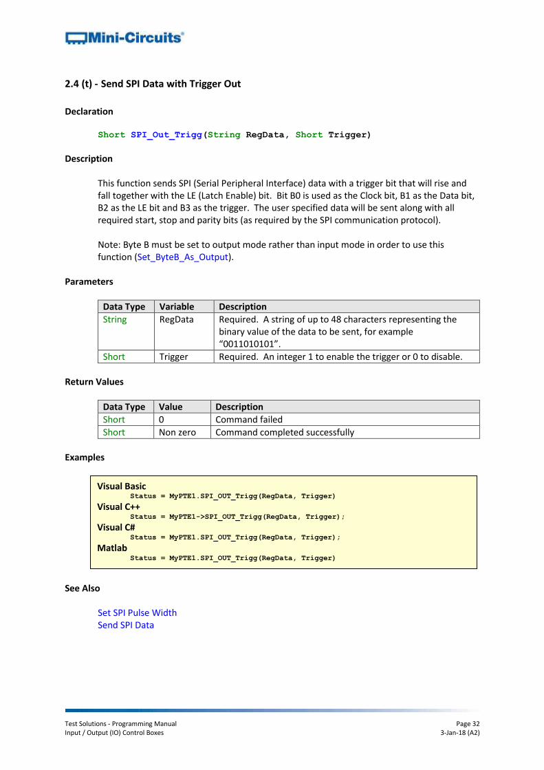
2.4 (t) - Send SPI Data with Trigger Out
Declaration Short SPI_Out_Trigg(String RegData, Short Trigger)
Description
This function sends SPI (Serial Peripheral Interface) data with a trigger bit that will rise and fall together with the LE (Latch Enable) bit. Bit B0 is used as the Clock bit, B1 as the Data bit, B2 as the LE bit and B3 as the trigger. The user specified data will be sent along with all required start, stop and parity bits (as required by the SPI communication protocol). Note: Byte B must be set to output mode rather than input mode in order to use this function (Set_ByteB_As_Output).
Parameters
Data Type Variable Description
String RegData Required. A string of up to 48 characters representing the binary value of the data to be sent, for example “0011010101”.
Short Trigger Required. An integer 1 to enable the trigger or 0 to disable.
Return Values
Data Type Value Description
Short 0 Command failed
Short Non zero Command completed successfully
Examples
See Also Set SPI Pulse Width Send SPI Data
Visual Basic Status = MyPTE1.SPI_OUT_Trigg(RegData, Trigger)
Visual C++ Status = MyPTE1->SPI_OUT_Trigg(RegData, Trigger);
Visual C# Status = MyPTE1.SPI_OUT_Trigg(RegData, Trigger);
Matlab Status = MyPTE1.SPI_OUT_Trigg(RegData, Trigger)

Test Solutions - Programming Manual Page 33 Input / Output (IO) Control Boxes 3-Jan-18 (A2)
2.4 (u) - Set Individual Relay
Declaration Short Set_Relay(Short RelayNo, Short On_Off)
Description
This function sets the state of an individual relay, either Com to NO (Common port connected to Normally Open port) or Com to NC (Common port connected to Normally Closed port). In the case of USB-I/O-4D2R, Com to NO turns on the 24V outputs and Com to NC turns them off.
Parameters (All Models Except USB-I/O-4D2R)
Data Type Variable Description
Short RelayNo Required. An integer (0 to 7) to determine which relay to set.
Short On_Off Required. An integer value to set the state of the relay, 0 for Com to NC state or 1 for Com to NO state.
Parameters (USB-I/O-4D2R Only)
Data Type Variable Description
Short RelayNo Required. An integer value to determine which output to set, 0 for OUT1 or 1 for OUT2.
Short On_Off Required. An integer value to set the state of the relay, 0 to turn off the 24V output, or 1 to turn on the 24V output.
Return Values
Data Type Value Description
Short 0 Command failed
Short Non zero Command completed successfully
Examples
See Also Set All Relays Read Relay States
Visual Basic Status = MyPTE1.Set_Relay(RelayNo, On_OFF)
Visual C++ Status = MyPTE1->Set_Relay(RelayNo, On_OFF);
Visual C# Status = MyPTE1.Set_Relay(RelayNo, On_OFF);
Matlab Status = MyPTE1.Set_Relay(RelayNo, On_OFF)

Test Solutions - Programming Manual Page 34 Input / Output (IO) Control Boxes 3-Jan-18 (A2)
2.4 (v) - Set All Relays
Declaration Short Set_RelayByte(Byte Val)
Description
This function sets the state of all relays at once. Each relay can be set to either Com to NO (Common port connected to Normally Open port) or Com to NC (Common port connected to Normally Closed port). In the case of USB-I/O-4D2R, Com to NO turns on the 24V outputs and Com to NC turns them off.
Parameters (All Models except USB-I/O-4D2R)
Data Type Variable Description
Byte Val Required. A byte indicating the state to which each relay should be set. Each bit indicates the state to which a specific relay should be set, from bit 0 (LSB) for relay 0 to bit 7 (MSB) for relay 7. Each bit can be 0 for Com to NC state or 1 for Com to NO state. For example to set output relay 0, 3 and 5 to “Com to NO”, with all others as “Com to NC”: Relay7=0, Relay6=0, Relay5=1, Relay4=0, Relay3=1, Relay2=0, Relay1=0, Relay0=1 Val = 00101001 (binary) = 41 (decimal)
Parameters (USB-I/O-4D2R Only)
Data Type Variable Description
Byte Val Required. A byte indicating the state to which each relay should be set. Bit 0 corresponds to OUT1 and bit 1 to OUT2, all other bits can be any value (“don’t care” bits). Each bit can be 1 to turn on the output or 0 to turn off the output. For example, to turn on OUT1 and turn off OUT2: Val = 00000001 (binary) = 1 (decimal)
Return Values
Data Type Value Description
Short 0 Command failed
Short Non zero Command completed successfully

Test Solutions - Programming Manual Page 35 Input / Output (IO) Control Boxes 3-Jan-18 (A2)
Examples
See Also Set Individual Relay Read Relay States
Visual Basic Status = MyPTE1.Set_RelayByte(Val)
Visual C++ Status = MyPTE1->Set_RelayByte(Val);
Visual C# Status = MyPTE1.Set_RelayByte(Val);
Matlab Status = MyPTE1.Set_RelayByte(Val)

Test Solutions - Programming Manual Page 36 Input / Output (IO) Control Boxes 3-Jan-18 (A2)
2.4 (w) - Read Relay States
Declaration Short Read_Relays_Byte(Byte RetVal)
Description
This function reads the state of all 8 relays simultaneously to determine whether they are in the Com to NO (Common port connected to Normally Open port) state or Com to NC (Common port connected to Normally Closed port) state. In the case of USB-I/O-4D2R, the function will determine whether the 24V outputs, OUT1 and OUT2, are on or off.
Parameters (All Models Except USB-I/O-4D2R)
Data Type Variable Description
Byte RetVal Required. A user defined byte which will be updated with the state of each relay should be set. Each bit indicates the state of a single relay, from bit 0 (LSB) for relay 0 to bit 7 (MSB) for relay 7. Each bit can be 0 for Com to NC state or 1 for Com to NO state. For example: RetVal = 25 (decimal) = 00110010 (decimal) Therefore, relays 1, 4 and 5 are in the “Com to NO” state, with all others in the “Com to NC” state.
Parameters (USB-I/O-4D2R Only)
Data Type Variable Description
Byte RetVal Required. A user defined byte which will be updated with the state of each relay should be set. Bit 0 corresponds to OUT1 and bit 1 to OUT2, all other bits will be 0. Each bit will be 0 if the 24V output is disconnected or 1 if the 24V output is connected. RetVal = 2 (decimal) = 00000010 (decimal) Therefore, OUT1 is off and OUT2 is on.
Return Values
Data Type Value Description
Short 0 Command failed
Short Non zero Command completed successfully

Test Solutions - Programming Manual Page 37 Input / Output (IO) Control Boxes 3-Jan-18 (A2)
Examples
See Also Set Individual Relay Set All Relays
Visual Basic Status = MyPTE1.Read_Relays_Byte(RetVal)
Visual C++ Status = MyPTE1->Read_Relays_Byte(RetVal);
Visual C# Status = MyPTE1.Read_Relays_Byte(RetVal);
Matlab [Status, Ret_ByteVal] = MyPTE1.Read_Relays_Byte(RetVal)

Test Solutions - Programming Manual Page 38 Input / Output (IO) Control Boxes 3-Jan-18 (A2)
2.4 (x) - Get Firmware
Declaration Short GetExtFirmware(Short A0, Short A1, Short A2, String Firmware)
Description
This function returns the internal firmware version of the control box along with three reserved variables (for factory use).
Parameters
Data Type Variable Description
Short A0 Required. User defined variable for factory use only.
Short A1 Required. User defined variable for factory use only.
Short A2 Required. User defined variable for factory use only.
String Firmware Required. User defined variable which will be updated with the current firmware version, for example “B3”.
Return Values
Data Type Value Description
Short 0 Command failed
Short 1 Command completed successfully
Examples
Visual Basic If MyPTE1.GetExtFirmware(A0, A1, A2, Firmware) > 0 Then
MsgBox ("Firmware version is " & Firmware)
End If Visual C++
if (MyPTE1->GetExtFirmware(A0, A1, A2, Firmware) > 0 )
{
MessageBox::Show("Firmware version is " + Firmware);
} Visual C#
if (MyPTE1.GetExtFirmware(ref(A0, A1, A2, Firmware)) > 0 )
{
MessageBox.Show("Firmware version is " + Firmware);
} Matlab
[status, A0, A1, A2, Firmware] = MyPTE1.GetExtFirmware(A0, A1, A2, Firmware)
if status > 0
h = msgbox('Firmware version is ', Firmware)
end

Test Solutions - Programming Manual Page 39 Input / Output (IO) Control Boxes 3-Jan-18 (A2)
3 - Operating in a Linux Environment To open a connection to Mini-Circuits’ input/output control boxes, the Vendor ID and Product ID are required:
Mini-Circuits Vendor ID: 0x20CE
Control Box Product ID: 0x21 Communication with the control box is carried out by way of USB Interrupt. The transmitted and received buffer sizes are 64 Bytes each:
Transmit Array = [Byte 0][Byte1][Byte2]…[Byte 63]
Returned Array = [Byte 0][Byte1][Byte2]…[Byte 63] In most cases, the full 64 byte buffer size is not needed so any unused bytes become “don’t care” bytes; they can take on any value without affecting the operation of the control box. Worked examples can be found in the Programming Examples & Troubleshooting Guide, downloadable from the Mini-Circuits website. The examples use the libhid and libusb libraries to interface with the IO control box as a USB HID (Human Interface Device).
3.1 - Summary of Commands
The commands that can be sent to the control box are summarized in the table below and detailed on the following pages.
# Description Command Code
(Byte 0) Comments
a Get Device Model Name 40
b Get Device Serial Number 41
c Get Status of Relays 35
d Set Single Relay 34
e Set All Relays 33
f Set Single TTL Bit 32
g Get TTL Bit 30
h Set TTL Byte 31
i Get TTL Byte 28
29
Byte A
Byte B
j Set Byte A As Input 24
k Set Byte B As Input 26
l Set Byte A As Output 25
m Set Byte B As Output 27
n Send SPI Output 36
o Send SPI Output With Trigger 37
p Set SPI Pulse Width 8
q Get Firmware 99

Test Solutions - Programming Manual Page 40 Input / Output (IO) Control Boxes 3-Jan-18 (A2)
3.2 - Detailed Description of Commands
3.2 (a) - Get Device Model Name
Description
This function determines the Mini-Circuits part number of the control box. Transmit Array
Send code 40 in BYTE0 of the transmit array. BYTE1 through to BYTE63 are don’t care bytes and can be any value.
Returned Array
The model name is represented as a series of ASCII characters in the returned array, starting from BYTE1. The final ASCII character is contained in the byte immediately preceding the first zero value byte. All subsequent bytes up to BYTE63 are “don’t care” bytes and could be any value.
Byte Byte 0 Byte 1 Byte 2 … Byte (N-1) Byte N
Description Code First
Char
Second
Char …
Last
Char
End
Marker
Value 40 ASCII ASCII … ASCII 0
Example
The following array would be returned for Mini-Circuits’ USB-IO-4D2R control box. See Appendix A for conversions between decimal, binary and ASCII characters.
Byte Byte 0 Byte 1 Byte 2 Byte 3 Byte 4 Byte 5 Byte 6
Description Code Char 1 Char 2 Char 3 Char 4 Char 5 Char 6
Value 40 85 83 42 45 73 79
ASCII Character N/A U S B - I O
Byte Byte 7 Byte 8 Byte 9 Byte 10 Byte 11 Byte 12
Description Char 7 Char 8 Char 9 Char 10 Char 11 End
Marker
Value 45 52 68 50 82 0
ASCII Character - 4 D 2 R N/A
See Also Get Device Serial Number
Byte Byte 0
Description Code
Value 40

Test Solutions - Programming Manual Page 41 Input / Output (IO) Control Boxes 3-Jan-18 (A2)
3.2 (b) - Get Device Serial Number
Description
This function determines the serial number of the connected control box. Transmit Array
Send code 41 in BYTE0 of the transmit array. BYTE1 through to BYTE63 are “don’t care” bytes and can be any value. Byte Byte 0
Description Code
Value 41
Returned Array
The serial number is represented as a series of ASCII characters in the returned array, starting from BYTE1. The final ASCII character is contained in the byte immediately preceding the first zero value byte. All subsequent bytes up to BYTE63 are “don’t care” bytes and could be any value.
Byte Byte 0 Byte 1 Byte 2 … Byte (N-1) Byte N
Description Code First
Char
Second
Char …
Last
Char
End
Marker
Value 41 ASCII ASCII … ASCII 0
Example
The following example indicates that the current control box has serial number 11301210001. See Appendix A for conversions between decimal, binary and ASCII characters. Byte Byte 0 Byte 1 Byte 2 Byte 3 Byte 4 Byte 5 Byte 6
Description Code Char 1 Char 2 Char 3 Char 4 Char 5 Char 6
Value 41 49 49 51 48 49 50
ASCII Character N/A 1 1 3 0 1 2
Byte Byte 7 Byte 8 Byte 9 Byte 10 Byte 11 Byte 12
Description Char 7 Char 8 Char 9 Char 10 Char 11 End
Marker
Value 49 48 48 48 49 0
ASCII Character 1 0 0 0 1 N/A
See Also Get Device Model Name

Test Solutions - Programming Manual Page 42 Input / Output (IO) Control Boxes 3-Jan-18 (A2)
3.2 (c) - Get Status of Relays
Description
This function returns the states of all relays at once. Each relay could be set to either Com to NO (Common port connected to Normally Open port) or Com to NC (Common port connected to Normally Closed port).
Transmit Array
Send code 35 in BYTE0 of the transmit array. BYTE1 through to BYTE63 are “don’t care” bytes and can be any value.
Byte Byte 0
Description Code
Value 35
Returned Array
Each bit in BYTE1 of the returned array represents the state of an individual relay, with bit 0 (LSB) representing relay 0 and bit 7 (MSB) representing relay 7. Each bit could be 1 for “Com to NO” or 0 for “Com to NC”. In the case of USB-I/O-4D2R, only bit 0 (LSB) and bit 1 of BYTE1 apply, with bit 0 representing OUT1 and bit 1 representing OUT2. Each bit could be 1 to indicate the 24V output is on or 0 indicate it is off. BYTE2 through to BYTE63 are “don’t care” bytes and can be any value.
Byte Byte 0 Byte 1
Description Code State
Value 35 0 to 255

Test Solutions - Programming Manual Page 43 Input / Output (IO) Control Boxes 3-Jan-18 (A2)
Example
Byte Byte 0 Byte 1
Description Code State
Value 33 7
The state of 7 in the above returned array can be interpreted as a binary number and broken down as below:
Bit Bit 7
(MSB) Bit 6 Bit 5 Bit 4 Bit 3 Bit 2 Bit 1
Bit 0 (LSB)
Description Relay 7
State
Relay 6
State
Relay 5
State
Relay 4
State
Relay 3
State
Relay 2
State
Relay 1
State
Relay 0
State
Value 0 0 0 0 1 0 1 1
This indicates relays 0, 1 and 3 are in the “Com to NO” state, with all other relays in the “Com to NC” state.
See Also Set Single Relay Set All Relays
Test Solutions - Programming Manual Page 44 Input / Output (IO) Control Boxes 3-Jan-18 (A2)
3.2 (d) - Set Single Relay
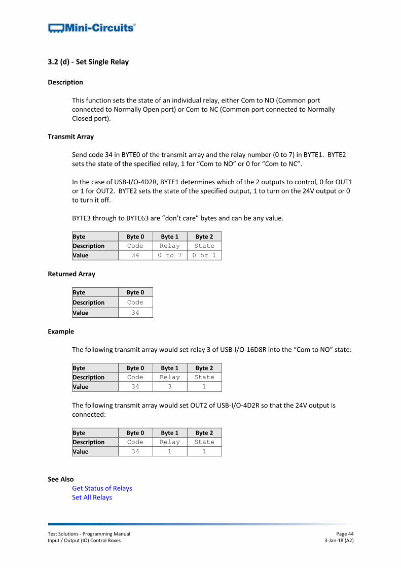
Description
This function sets the state of an individual relay, either Com to NO (Common port connected to Normally Open port) or Com to NC (Common port connected to Normally Closed port).
Transmit Array
Send code 34 in BYTE0 of the transmit array and the relay number (0 to 7) in BYTE1. BYTE2 sets the state of the specified relay, 1 for “Com to NO” or 0 for “Com to NC”. In the case of USB-I/O-4D2R, BYTE1 determines which of the 2 outputs to control, 0 for OUT1 or 1 for OUT2. BYTE2 sets the state of the specified output, 1 to turn on the 24V output or 0 to turn it off. BYTE3 through to BYTE63 are “don’t care” bytes and can be any value.
Byte Byte 0 Byte 1 Byte 2
Description Code Relay State
Value 34 0 to 7 0 or 1
Returned Array
Byte Byte 0
Description Code
Value 34
Example
The following transmit array would set relay 3 of USB-I/O-16D8R into the “Com to NO” state: Byte Byte 0 Byte 1 Byte 2
Description Code Relay State
Value 34 3 1
The following transmit array would set OUT2 of USB-I/O-4D2R so that the 24V output is connected: Byte Byte 0 Byte 1 Byte 2
Description Code Relay State
Value 34 1 1
See Also Get Status of Relays Set All Relays

Test Solutions - Programming Manual Page 45 Input / Output (IO) Control Boxes 3-Jan-18 (A2)
3.2 (e) - Set All Relays
Description
This function sets the state of all relays at once. Each relay can be set to either Com to NO (Common port connected to Normally Open port) or Com to NC (Common port connected to Normally Closed port).
Transmit Array
Send code 33 in BYTE0 of the transmit array. Each bit in BYTE1 represents the required state of an individual relay, with bit 0 (LSB) representing relay 0 and bit 7 (MSB) representing relay 7. Each bit can be 1 for “Com to NO” or 0 for “Com to NC”. In the case of USB-I/O-4D2R, only bit 0 (LSB) and bit 1 of BYTE1 apply, with bit 0 representing OUT1 and bit 1 representing OUT2. Each bit can be set to 1 to turn on the 24V output or 0 to turn it off. BYTE2 through to BYTE63 are “don’t care” bytes and can be any value.
Byte Byte 0 Byte 1
Description Code State
Value 33 0 to 255
Returned Array
Byte Byte 0
Description Code
Value 33
Example
To set relays 0, 1 and 3 into the “Com to NO” state, with all other relays in the “Com to NC” state, the following byte would be sent for BYTE1:
Bit Bit 7
(MSB) Bit 6 Bit 5 Bit 4 Bit 3 Bit 2 Bit 1
Bit 0 (LSB)
Description Relay 7
State
Relay 6
State
Relay 5
State
Relay 4
State
Relay 3
State
Relay 2
State
Relay 1
State
Relay 0
State
Value 0 0 0 0 1 0 1 1
The byte to send in BYTE1 is therefore 00001011 binary which equates to a decimal value of 7. The complete transmit array would be: Byte Byte 0 Byte 1
Description Code State
Value 33 7
See Also

Test Solutions - Programming Manual Page 46 Input / Output (IO) Control Boxes 3-Jan-18 (A2)
Get Status of Relays Set Single Relay

Test Solutions - Programming Manual Page 47 Input / Output (IO) Control Boxes 3-Jan-18 (A2)
3.2 (f) - Set Single TTL Bit
Description
This function sets the state of a single output bit specified by the user. Bits A0 to A7 and B0 to B7 can be set (model dependent). The value of each bit can be set to logic “low” (0) or logic “high” (1). Note: The relevant byte must be set to output mode rather than input mode in order to use this function.
Transmit Array
The transmit array is made up of the following bytes:
BYTE0 o Code 32
BYTE1 o ASCII character code to indicate which output byte is to be used; the code is
65 for byte A or 66 for byte B
BYTE2 o An integer value to indicate which bit within the byte is to be set, from 0 for
bit 0 (LSB) to 7 for bit 7 (MSB)
BYTE3 o The state of the specified bit, either 0 (logic low) or 1 (logic high)
BYTE4 to BYTE63 o Can be any value (“don’t care” bytes)
For USB-I/O-4D2R, only bits 0 to 3 of Byte B are available.
Byte Byte 0 Byte 1 Byte 2 Byte 3
Description Code Byte Bit State
Value 32 65 or 66 0 to 7 0 or 1
Returned Array
Byte Byte 0
Description Code
Value 32
Example
To set bit “B3” (bit 3 of byte B) to logic high, the following transmit array would be sent:
Byte Byte 0 Byte 1 Byte 2 Byte 3
Description Code Byte Bit State
Value 32 66 3 1

Test Solutions - Programming Manual Page 48 Input / Output (IO) Control Boxes 3-Jan-18 (A2)
See Also Get Single TTL Bit
Set TTL Byte

Test Solutions - Programming Manual Page 49 Input / Output (IO) Control Boxes 3-Jan-18 (A2)
3.2 (g) - Get Single TTL Bit
Description
This function gets the state of a single TTL input bit from digital byte A or byte B, as specified by the user. Bits A0 to A7 and B0 to B7 are available. The value of each bit could be logic “low” (0) or logic “high” (1). This function is not available for USB-I/O-4D2R. Note: The relevant byte must be set to input mode rather than output mode in order to use this function.
Transmit Array
The transmit array is made up of the following bytes:
BYTE0 o Code 30
BYTE1 o ASCII character code to indicate which input byte is to required; the code is
65 for byte A or 66 for byte B
BYTE2 o An integer value to indicate which bit within the byte is to be set, from 0 for
bit 0 (LSB) to 7 for bit 7 (MSB)
BYTE3 to BYTE63 o Can be any value (“don’t care” bytes)
Byte Byte 0 Byte 1 Byte 2
Description Code Byte Bit
Value 30 65 or 66 0 to 7
Returned Array
The returned array contains the TTL logic value (0 or 1) of the requested bit in BYTE1.
Byte Byte 0 Byte1
Description Code Value
Value 30 0 or 1

Test Solutions - Programming Manual Page 50 Input / Output (IO) Control Boxes 3-Jan-18 (A2)
Example
To read bit “B3” (bit 3 of byte B), the following transmit array would be sent:
Byte Byte 0 Byte 1 Byte 2
Description Code Byte Bit
Value 32 66 3
The following array would be returned to indicate the input was at logic high: Byte Byte 0 Byte1
Description Code Value
Value 30 1
See Also Set Single TTL Bit
Set TTL Byte

Test Solutions - Programming Manual Page 51 Input / Output (IO) Control Boxes 3-Jan-18 (A2)
3.2 (h) - Set TTL Byte
Description
This function sets the state of output byte A or byte B so that each bit is logic “low” (0) or logic “high” (1). Note: The relevant byte must be set to output mode rather than input mode in order to use this function.
Transmit Array
The transmit array is made up of the following bytes:
BYTE0 o Code 31
BYTE1 o ASCII character code to indicate which output byte is to be used; the code is
65 for byte A or 66 for byte B
BYTE2 o The output state for the TTL byte
BYTE3 to BYTE63 o Can be any value (“don’t care” bytes)
For USB-I/O-4D2R, only bits 0 to 3 of Byte B are available.
Byte Byte 0 Byte 1 Byte 2
Description Code Byte State
Value 31 65 or 66 0 to 255
Returned Array
Byte Byte 0
Description Code
Value 31

Test Solutions - Programming Manual Page 52 Input / Output (IO) Control Boxes 3-Jan-18 (A2)
Example
To set byte A to the below state (1 indicating logic high and 0 indicating) logic low:
Bit Bit 7
(MSB) Bit 6 Bit 5 Bit 4 Bit 3 Bit 2 Bit 1
Bit 0 (LSB)
Description State State State State State State State State
Value 0 0 0 0 1 0 1 1
The binary value is 00001011 which equates to a decimal value of 11. The transmit array would therefore be:
Byte Byte 0 Byte 1 Byte 2
Description Code Byte State
Value 11 65 11
See Also Get TTL Byte Set Single TTL Bit

Test Solutions - Programming Manual Page 53 Input / Output (IO) Control Boxes 3-Jan-18 (A2)
3.2 (i) - Get TTL Byte
Description
This function reads the state of digital input byte A or byte B. Each bit within the byte could be logic “low” (0) or logic “high” (1). Notes:
1. This function is not available for USB-I/O-4D2R 2. The relevant byte must be set to input mode rather than output mode in order to
use this function
Transmit Array
The transmit array is made up of the following bytes:
BYTE0 o Code 28 for Byte A or 29 for Byte B
BYTE1 to BYTE63 o Can be any value (“don’t care” bytes)
Byte Byte 0
Description Code
Value 28 or 29
Returned Array
The returned array repeats code 28 or 29 in BYTE0 and contains a numeric value representing the state of the required byte in BYTE1. BYTE2 to BYTE63 could be any value (“don’t care” bytes). The value in BYTE1 of the returned array should be interpreted as a binary number, with each bit corresponding to a digital input bit within the byte, from 0 for bit 0 (LSB) to 7 for bit 7 (MSB).
Byte Byte 0 Byte 1
Description Code Value
Value 28 or 29 Binary

Test Solutions - Programming Manual Page 54 Input / Output (IO) Control Boxes 3-Jan-18 (A2)
Example
Send the following array to read the input state of byte A:
Byte Byte 0
Description Code
Value 28
The following returned array indicates the input state of byte A is 11:
Byte Byte 0 Byte 1
Description Code State
Value 28 11
To determine the state of each individual input bit of byte A, the decimal value 11 should be interpreted as a binary number (00001011). Each bit in the binary number confirms whether the corresponding input bit is at logic low (0) or logic high (1):
Bit Bit 7
(MSB) Bit 6 Bit 5 Bit 4 Bit 3 Bit 2 Bit 1
Bit 0 (LSB)
Description State State State State State State State State
Value 0 0 0 0 1 0 1 1
See Also Set TTL Byte Get Single TTL Bit

Test Solutions - Programming Manual Page 55 Input / Output (IO) Control Boxes 3-Jan-18 (A2)
3.2 (j) - Set Byte A As Input
Description
This function changes the mode of byte A so that it acts as an input, rather than an output. By default Byte A is an output. This command is available for USB-I/O-16D8R only.
Transmit Array
Send code 24 in BYTE0 of the transmit array. BYTE1 to BYTE63 can be any value (“don’t care” bytes).
Byte Byte 0
Description Code
Value 24
Returned Array
Byte Byte 0
Description Code
Value 24
See Also
Set Byte B As Input Set Byte A As Output Set Byte B As Output

Test Solutions - Programming Manual Page 56 Input / Output (IO) Control Boxes 3-Jan-18 (A2)
3.2 (k) - Set Byte B As Input
Description
This function changes the mode of byte B so that it acts as an input, rather than an output. By default Byte B is an output. This command is not available for USB-I/O-4D2R.
Transmit Array
Send code 26 in BYTE0 of the transmit array. BYTE1 to BYTE63 can be any value (“don’t care” bytes).
Byte Byte 0
Description Code
Value 26
Returned Array
Byte Byte 0
Description Code
Value 26
See Also
Set Byte A As Input Set Byte A As Output Set Byte B As Output

Test Solutions - Programming Manual Page 57 Input / Output (IO) Control Boxes 3-Jan-18 (A2)
3.2 (l) - Set Byte A As Output
Description
This function changes the mode of byte A so that it acts as an output, rather than an input. By default Byte A is an output. This command is not available for USB-I/O-4D2R.
Transmit Array
Send code 25 in BYTE0 of the transmit array. BYTE1 to BYTE63 can be any value (“don’t care” bytes).
Byte Byte 0
Description Code
Value 25
Returned Array
Byte Byte 0
Description Code
Value 25
See Also
Set Byte A As Input Set Byte B As Input
Set Byte B As Output

Test Solutions - Programming Manual Page 58 Input / Output (IO) Control Boxes 3-Jan-18 (A2)
3.2 (m) - Set Byte B As Output
Description
This function changes the mode of byte B so that it acts as an output, rather than an input. By default Byte B is an output. This command is not available for USB-I/O-4D2R.
Transmit Array
Send code 27 in BYTE0 of the transmit array. BYTE1 to BYTE63 can be any value (“don’t care” bytes).
Byte Byte 0
Description Code
Value 27
Returned Array
Byte Byte 0
Description Code
Value 27
See Also
Set Byte A As Input Set Byte B As Input
Set Byte A As Output

Test Solutions - Programming Manual Page 59 Input / Output (IO) Control Boxes 3-Jan-18 (A2)
3.2 (n) - Send SPI Output
Description
This function sends SPI (Serial Peripheral Interface) data. The Clock bit, Data bit and LE (Latch Enable) bits to be used are defined by the user. The user specified binary data will be sent along with all required start, stop and parity bits (as required by the SPI communication protocol). Notes:
1. For USB-I/O-4D2R, only bits 0 to 3 of Byte B are available 2. The relevant byte must be set to output mode rather than input mode in order to
use this function.
Transmit Array
The transmit array is made up of the following bytes:
BYTE0 o Code 36
BYTE1 o ASCII character code to indicate which output byte is to be used for the
Clock; the code is 65 for byte A or 66 for byte B
BYTE2 o An integer value to indicate which bit within the byte is to be used for the
Clock, from 0 for bit 0 (LSB) to 7 for bit 7 (MSB)
BYTE3 o ASCII character code to indicate which output byte is to be used for the Data;
the code is 65 for byte A or 66 for byte B
BYTE4 o An integer value to indicate which bit within the byte is to be used for the
Data, from 0 for bit 0 (LSB) to 7 for bit 7 (MSB)
BYTE5 o ASCII character code to indicate which output byte is to be used for the LE
(Latch Enable); the code is 65 for byte A or 66 for byte B
BYTE6 o An integer value to indicate which bit within the byte is to be used for the LE,
from 0 for bit 0 (LSB) to 7 for bit 7 (MSB)
BYTE7 o The number of data bits to be sent (N), not including the parity, start or stop
bits. o Maximum value for N is 48
BYTE8 to BYTE[N+7] o Each byte represents one SPI data bit to send with value 0 or 1
BYTE[N+8] to BYTE63 o Can be any value (“don’t care” bytes)
Byte Byte 0 Byte 1 Byte 2 Byte 3 Byte 4 Byte 5 Byte 6

Test Solutions - Programming Manual Page 60 Input / Output (IO) Control Boxes 3-Jan-18 (A2)
Description Code Clock
Byte
Clock
Bit
Data
Byte
Data
Bit
LE
Byte
LE
Bit
Value 36 65 or 66 0 to 7 65 or 66 0 to 7 65 or 66 0 to 7
Byte Byte 7 Byte 8 … Byte [N+7]
Description No. Data
Bits (N)
Data
Bit 1 …
Data
Bit N
Value 1 to 48 0 or 1 … 0 or 1
Returned Array
Byte Byte 0
Description Code
Value 36
Example
Use the following transmit array to send SPI data “10010” using B0 as Clock, B1 as Data and B2 as LE:
Byte Byte 0 Byte 1 Byte 2 Byte 3 Byte 4 Byte 5 Byte 6
Description Code Clock
Byte
Clock
Bit
Data
Byte
Data
Bit
LE
Byte
LE
Bit
Value 36 66 0 66 1 66 2
Byte Byte 7 Byte 8 Byte 9 Byte 10 Byte 11 Byte 12
Description No. Data
Bits (N)
Data
Bit 1
Data
Bit 2
Data
Bit 3
Data
Bit 4
Data
Bit 5
Value 5 1 0 0 1 0
See Also Send SPI Output With Trigger Set SPI Pulse Width
Test Solutions - Programming Manual Page 61 Input / Output (IO) Control Boxes 3-Jan-18 (A2)
3.2 (o) - Send SPI Output with Trigger
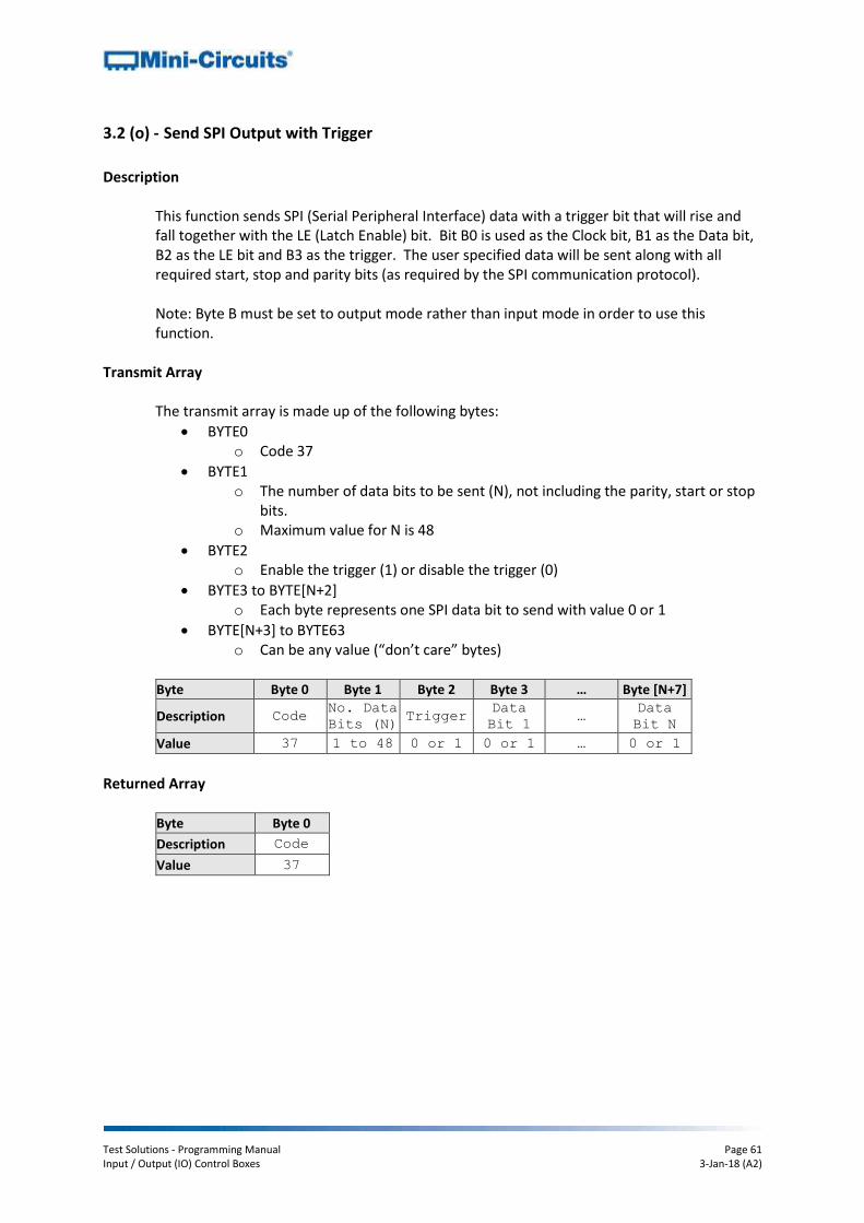
Description
This function sends SPI (Serial Peripheral Interface) data with a trigger bit that will rise and fall together with the LE (Latch Enable) bit. Bit B0 is used as the Clock bit, B1 as the Data bit, B2 as the LE bit and B3 as the trigger. The user specified data will be sent along with all required start, stop and parity bits (as required by the SPI communication protocol).
Note: Byte B must be set to output mode rather than input mode in order to use this function.
Transmit Array
The transmit array is made up of the following bytes:
BYTE0 o Code 37
BYTE1 o The number of data bits to be sent (N), not including the parity, start or stop
bits. o Maximum value for N is 48
BYTE2 o Enable the trigger (1) or disable the trigger (0)
BYTE3 to BYTE[N+2] o Each byte represents one SPI data bit to send with value 0 or 1
BYTE[N+3] to BYTE63 o Can be any value (“don’t care” bytes)
Byte Byte 0 Byte 1 Byte 2 Byte 3 … Byte [N+7]
Description Code No. Data
Bits (N) Trigger
Data
Bit 1 …
Data
Bit N
Value 37 1 to 48 0 or 1 0 or 1 … 0 or 1
Returned Array
Byte Byte 0
Description Code
Value 37

Test Solutions - Programming Manual Page 62 Input / Output (IO) Control Boxes 3-Jan-18 (A2)
Example
Use the following transmit array to send SPI data “10010111” with the trigger enabled:
Byte Byte 0 Byte 1 Byte 2 Byte 3 Byte 4 Byte 5 Byte 6
Description Code No. Data
Bits (N) Trigger
Data
Bit 1
Data
Bit 2
Data
Bit 3
Data
Bit 4
Value 37 8 1 1 0 0 1
Byte Byte 7 Byte 0 Byte 1 Byte 2
Description Data
Bit 5
Data
Bit 6
Data
Bit 7
Data
Bit 8
Value 0 1 1 1
See Also Send SPI Output Set SPI Pulse Width

Test Solutions - Programming Manual Page 63 Input / Output (IO) Control Boxes 3-Jan-18 (A2)
3.2 (p) - Set SPI Pulse Width
Description
This function sets the pulse width that will be used for the Clock, Data and LE (Latch Enable) connections when the control box is used for SPI (Serial Peripheral Interface) communication. The pulse width can be set as any integer value from 0 to 255μs although in practice the minimum pulse width will be approximately 0.08μs. The default value is 10μs. Note: The duty cycle remains constant at 50% so clock frequency will change as pulse width is varied.
Transmit Array
The transmit array is made up of the following bytes:
BYTE0 o Code 8
BYTE1 o Pulse width in micro-seconds, from 0 to 255
BYTE2 to BYTE63 o Can be any value (“don’t care” bytes)
Byte Byte 0 Byte 1
Description Code Byte
Value 8 0 to 255
Returned Array
Byte Byte 0
Description Code
Value 8
Example
To set the pulse width to 5μs, send:
Byte Byte 0 Byte 1
Description Code Byte
Value 8 5
See Also
Send SPI Output Send SPI Output With Trigger

Test Solutions - Programming Manual Page 64 Input / Output (IO) Control Boxes 3-Jan-18 (A2)
3.2 (q) - Get Firmware
Description
This function returns the internal firmware version of the control box.
Transmit Array
Send code 99 in BYTE0 of the transmit array (BYTE1 through BYTE63 can be any value).
Byte Byte 0
Description Code
Value 99
Returned Array
The firmware version will be returned in BYTE5 and BYTE6 as ASCII character codes representing the letter and number of the firmware. BYTE1 through to BYTE4 contain internal Mini-Circuits reference codes and BYTE7 through to BYTE63 are “don’t care” bytes and could be any value.
Byte Byte 0 Byte 1 Byte 2 Byte 3 Byte 4 Byte 5 Byte 6
Description Code Reserved Reserved Reserved Reserved Firmware
Letter
Firmware
Number
Value 99 ASCII ASCII ASCII ASCII ASCII ASCII
Example
The following return array would indicate that the current firmware version is C3: Byte Byte 0 Byte 1 Byte 2 Byte 3 Byte 4 Byte 5 Byte 6
Description Code Reserved Reserved Reserved Reserved Firmware
Letter
Firmware
Number
Value 99 ASCII ASCII ASCII ASCII ASCII ASCII
ASCII Character N/A 7 4 S W C 3