TEST REPORT ON METAL ROOFING SYSTEMS INC. … report on metal roofing systems inc. system 2500 roof...
39
TL-327 TEST REPORT ON METAL ROOFING SYSTEMS INC. SYSTEM 2500 ROOF PANELS (24 GA., 2" HIGH, 16” WIDE FLAT PAN PANEL) AT 1' 0" & 5' 0" PURLIN SPACING WITH 180º SEAM IN ACCORDANCE WITH ASTM E1592-05 TESTED FOR: Metal Roofing Systems, Inc. 7687 Mikron Drive Stanley, NC 28164 Telephone: (704) 820-3110 FAX: (704) 820-0113 TESTED BY: ENCON ® Technology, Inc. 6717 South Yale Avenue, Suite 200 Tulsa, OK 74136 Telephone: (918) 492-5992 FAX: (918) 493-3568 TEST CONDUCTED AT: ENCON Testing Lab 1216 North Lansing Avenue, Suite C Tulsa, OK 74106 TEST WITNESSED BY: Bala Sockalingam, Ph.D., P.E. TESTING DATES: May 28 & 29, 2008 REPORTING DATE: May 30, 2008 ENCON ® Project C1588-1
Transcript of TEST REPORT ON METAL ROOFING SYSTEMS INC. … report on metal roofing systems inc. system 2500 roof...

TL-327
TEST REPORT ON
METAL ROOFING SYSTEMS INC. SYSTEM 2500 ROOF PANELS
(24 GA., 2" HIGH, 16” WIDE FLAT PAN PANEL) AT 1' 0" & 5' 0" PURLIN SPACING
WITH 180º SEAM IN ACCORDANCE WITH ASTM E1592-05
TESTED FOR:
Metal Roofing Systems, Inc. 7687 Mikron Drive Stanley, NC 28164
Telephone: (704) 820-3110 FAX: (704) 820-0113
TESTED BY:
ENCON® Technology, Inc. 6717 South Yale Avenue, Suite 200
Tulsa, OK 74136 Telephone: (918) 492-5992
FAX: (918) 493-3568
TEST CONDUCTED AT: ENCON Testing Lab
1216 North Lansing Avenue, Suite C Tulsa, OK 74106
TEST WITNESSED BY: Bala Sockalingam, Ph.D., P.E.
TESTING DATES: May 28 & 29, 2008 REPORTING DATE: May 30, 2008
ENCON® Project C1588-1

TABLE OF CONTENTS Page Number
SECTION I TEST SUMMARY 1.1 Summary 1 1.2 Roof Description 1 1.3 Test Results 1 1.4 Roof System Details 2-4 SECTION II DESCRIPTION OF TEST 2.1 Description of Test 5
2.1.1 Test Chamber 5 2.1.2 Air System 5 2.1.3 Deflection and Distortion Measurements 5 2.1.4 Test Procedure 5 2.1.5 Test Specimen 6 2.1.6 Specimen Width and Length 6 2.1.7 Specimen Orientation and Sealing 6 2.1.8 Failure 7
2.2 Factor of Safety 7
SECTION III TEST RESULTS 3.1 Specimen Identification 8 3.2 Test Results for 5' 0" span 9-11 3.3 Test Results for 1' 0" span 12-14 SECTION IV TEST PHOTOGRAPHS 4.1 Test Photographs 15-19
SECTION V APPENDIX
5.1 Test Drawings 20-25 5.2 Yield Stress 26
5.3 Test Conditions 27-28

TEST SUMMARY
ENCON Technology Inc. Page 1/28 5/30/2008 C1588-1
1.1 SUMMARY
Tests were conducted on Metal Roofing Systems’ System 2500 (2" high seam, 16" wide, 24 Ga., 50 ksi) standing seam metal roof panels at ENCON® Technology, Inc.'s Test Facility, Tulsa, Oklahoma. These tests meet the provisions of ASTM E 1592-05 and were run for different purlin spacing. The tests are listed below according to their configurations and date tested. Test #1: 16" wide, 24 ga. System 2500 panel at 5' 0" purlin spacing with 180º seam. Tested on
May 28, 2008.
Test #2: 16" wide, 24 ga. System 2500 panel at 1' 0" purlin spacing with 180º seam. Tested on May 29, 2008.
The above defined tests were witnessed by Bala Sockalingam, Ph.D., P.E., of ENCON Technology. 1.2 ROOF SYSTEM DESCRIPTION Metal Roofing’s System 2500 roof system consisted of 16" wide, 24 ga., 50 ksi (nom.) yield panels joined together at the sidelaps to form a flat pan profile with a 2" high seam. The panels are attached to the 16 ga. (nom) purlins at 5' 0" & 1' 0" spacing with two piece sliding clips and (2) #10-16 self-drilling screws per clip. The panel sidelaps were mechanically seamed to form a 180º seam. 1.3 TEST RESULTS The panels were loaded to a failure condition and observations made. In both tests, the failure mode was the bending failure of the clip base. The ultimate and design loads for all tests are shown on Table 1. Table 1. Test Results for 16" wide, 24 ga. System 2500 Panel
Test Purlin Spacing
Ultimate Load (psf)
Design Load (psf)
1 5’ 0” 40.2 20.1
2 1’ 0” 180.5 90.3 Notes: 1. The design load is calculated by dividing the ultimate load by the factor of safety of 2. 2. The design loads have not been increased by 33% for wind load.


DESCRIPTION OF TEST
ENCON Technology Inc. Page 5/28 5/30/2008 C1588-1
2.1 DESCRIPTION OF TEST Tests were conducted to determine the structural performance of the SSMR Panel at various span configurations under uniform static pressure difference. The test method consisted of the following: (1) sealing the test specimen against one face of a test chamber; (2) supplying air to and exhausting air from the chamber at the rate required to maintain the test pressure difference across the specimen; and (3) observing, measuring, and recording the deflections, deformations, and nature of any failures of principal or critical elements of the panel profile or members of the anchor system. The increments of load application were chosen such that a sufficient number of readings were obtained to determine the load deformation curve of the system. End and edge restraint was representative of field conditions, and the unit contained sufficient individual components to minimize the effect of variations in material and workmanship. 2.1.1 TEST CHAMBER The test chamber consisted of a box as shown in the applicable drawings in Section V. It contains one open surface against which the test specimen is installed. Two static pressure taps are located at corners to measure the chamber pressure in such a manner that the readings are not affected by the velocity of the air supply to or from the chamber or other air movement. The air supply openings into the chamber are arranged so that the air does not impinge directly on the test specimen with significant velocity. 2.1.2 AIR SYSTEM The compressed air supply consists of a number of individual compressor units capable of maintaining a constant air pressure difference for the required test period. A digital manometer is used to measure the test pressure difference with accuracy of 1/10". 2.1.3 DEFLECTION AND DISTORTION MEASUREMENT Deflection and distortion measurements were taken by means of a level and staffs calibrated to 1/100 of an inch, which were attached to the topside of the specimen. The deflection staffs were placed so that movement of the support members did not influence their readings. Reading locations are as shown on the drawings in Section V. 2.1.4 TEST PROCEDURE A nominal air pressure of 7.8 psf, which was equivalent to four times the dead weight of the specimen, was applied to the test panel for at least a minimum of 60 seconds and until the panel had stabilized and readings were taken. These readings were considered as bench mark readings and the load corresponding to these readings were considered as "Reference Zero Load." The air pressure was then increased by load increments as shown on recorded data and held for 60 seconds and until the panel had stabilized and the first set of readings were measured for the test panel. The air pressure was then reduced to zero or no load and then once again to the Reference

DESCRIPTION OF TEST
ENCON Technology Inc. Page 6/28 5/30/2008 C1588-1
Zero Load and the bench mark readings were taken. This procedure was repeated several times each time increasing the air pressure by a load increment over the previous load. It was ensured that benchmark readings were taken between each incremental increase in order to keep track of permanent deflections. This load sequence was continued until the panel was subjected to maximum air pressure resulting in its failure. 2.1.5 TEST SPECIMEN The test specimen was of sufficient size to determine the performance of all typical parts of the roof system excluding support elements such as purlins, eave struts, rake angles and similar structural parts supporting the roof system. Conditions of structural support of the roof specimen were simulated as accurately as possible. The test specimen included roof panels, concealed anchor clips and perimeter attachment of the roof to its structural supports. All of the parts of the test specimen were actual size and material. The overall dimension of the specimen was 7.75' x 25.0' for 5' 0" span test and 7.75' x 10.0' for 1' 0" span test. The panels were supported by secondary structures (purlins). The details of methods of construction and anchorage are depicted in the enclosed test drawings At the discontinuous end of test panel representing the building "cut side" (Detail 1/6), the only attachment to the underlying purlin was the panel clip. This "cut side" was constructed as if an actual building panel was physically severed into two pieces leaving the test edge of the panel discontinuous in a substantially unsupported condition. Endwall edges "cut end" (Details 1/3 and 1/4) were attached to rake angles or other structural elements by clamps. One eave/sidewall (Detail 1/5) and the panels in the main field of the test setup including the panel clips and its attachment to the secondary structure (purlins) were constructed similar to the panel mounting system that would be used to mount the panel to an actual building structure. The panel clip is hooked to the male lip of the panel and is attached to the purlin. See Drawings 1/1 and 1/2 for typical location of panel clips and Drawings 1/3 and 1/4 for locations of the panel clip relative to the various edge conditions. Plastic sheeting (max 6 mil thick) was used to keep the air pressure chamber airtight. The sheeting was placed between the purlins and panels. The sheeting between panel clips was pleated to allow the sheeting to flow into the panel sidelap when air pressure was applied to the panels. 2.1.6 SPECIMEN WIDTH & LENGTH The specimen width contained no less than five full panels and five structural elements. Edge seals did not constrain the specimen any more than normal gable attachment. With two ends crosswise restraint, the panels spanned 5 equal spans of 5' 0". With only one end crosswise restraint, the panels spanned 10 equal spans of 1' 0". 2.1.7 SPECIMEN ORIENTATION AND SEALING The test specimen was installed in its "as used" orientation, i.e., the interior side of the specimen faced the applied air pressure. The panel was secured to the test jig by the same number and type of

DESCRIPTION OF TEST
ENCON Technology Inc. Page 7/28 5/30/2008 C1588-1
concealed anchor clips as are normally used for installation of the test specimen on a building. The use of tape or film did not restrict differential movement between adjoining members. 2.1.8 FAILURE Failure was considered to have occurred when components separated or permanent distortion interfered with the function of the system or the system was unable to carry additional load. Permanent deformation of the panel across the flat (area between the ribs) which does not adversely affect roof watertightness or roof performance was not considered failure. 2.2 FACTOR OF SAFETY
The design loads was calculated with factor of safety of 2 as per AISI-NAS 2001 Specifications and 2004 Supplement.

TEST RESULTS
ENCON Technology Inc. Page 8/28 5/30/2008 C1588-1
3.1 SPECIMEN IDENTIFICATION
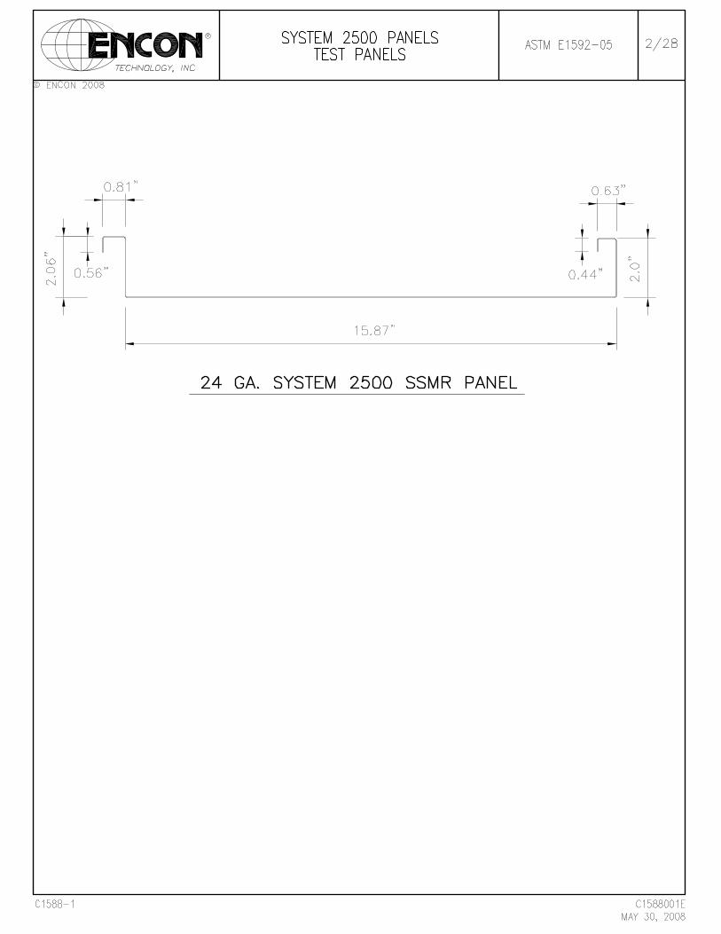
Manufacturer: Metal Roofing Systems Model Type: System 2500 Panel Dimensions: 2" high seam, 16" wide flat pan profile with 180º seam Panel Gauge: 24 ga. Base Metal Thickness: 0.020" Panel Yield Strength: 53.5 ksi Elongation in 2": 24 % Panel Coating: Painted Finish Clip Type: System 2500 two piece sliding clip Clip Material: Clip tab - 0.030" thick, 1.75" wide Clip base - 0.044" thick, 5.0" wide Fasteners: (2) #10-16 SDS Purlin: 16 ga. (0.058" thick) Note: All the test materials were supplied by Metal Roofing Systems and were not sampled by ENCON.
TEST RESULTS
ENCON Technology Inc. Page 9/28 5/30/2008 C1588-1
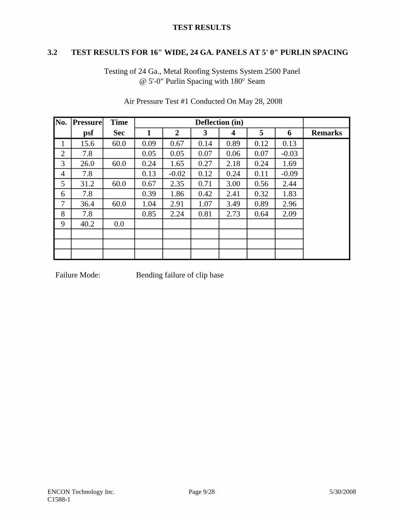
3.2 TEST RESULTS FOR 16" WIDE, 24 GA. PANELS AT 5' 0" PURLIN SPACING
Testing of 24 Ga., Metal Roofing Systems System 2500 Panel@ 5'-0" Purlin Spacing with 180° Seam
Air Pressure Test #1 Conducted On May 28, 2008
No. Pressure Time Deflection (in) psf Sec 1 2 3 4 5 6 Remarks
1 15.6 60.0 0.09 0.67 0.14 0.89 0.12 0.13 2 7.8 0.05 0.05 0.07 0.06 0.07 -0.033 26.0 60.0 0.24 1.65 0.27 2.18 0.24 1.694 7.8 0.13 -0.02 0.12 0.24 0.11 -0.095 31.2 60.0 0.67 2.35 0.71 3.00 0.56 2.446 7.8 0.39 1.86 0.42 2.41 0.32 1.837 36.4 60.0 1.04 2.91 1.07 3.49 0.89 2.968 7.8 0.85 2.24 0.81 2.73 0.64 2.099 40.2 0.0
Failure Mode: Bending failure of clip base

TEST RESULTS
ENCON Technology Inc. Page 10/28 5/30/2008 C1588-1
Load vs Panel Flat Deflections5' 0" Span (24 ga.) with 180º Seam
0.0
10.0
20.0
30.0
40.0
0.0 1.0 2.0 3.0 4.0
Deflections (in)
Air
Pre
ssur
e (p
sf)
#2 #4 #6#2 P Set #4 P set #6 P Set
Note: P Set denotes permanent deflection after each load cycle.

TEST RESULTS
ENCON Technology Inc. Page 11/28 5/30/2008 C1588-1
Load vs Panel Rib Deflections5' 0" Span (24 ga.) with 180º Seam
0.0
10.0
20.0
30.0
40.0
0.00 0.25 0.50 0.75 1.00 1.25
Deflections (in)
Air
Pre
ssur
e (p
sf)
#1 #3 #5#1 P Set #3 P set #5 P Set
Note: P Set denotes permanent deflection after each load cycle.

TEST RESULTS
ENCON Technology Inc. Page 12/28 5/30/2008 C1588-1
3.3 TEST RESULTS FOR 16" WIDE, 24 GA. PANELS AT 1' 0" PURLIN SPACING
Testing of 24 Ga., Metal Roofing Systems System 2500 Panel@ 1'-0" Purlin Spacing with 180° Seam
Air Pressure Test #2 Conducted On May 29, 2008
No. Pressure Time Deflection (in) psf Sec 1 2 3 4 5 6 Remarks
1 62.4 60.0 0.13 2.42 0.15 2.69 0.14 2.96 2 7.8 0.03 0.66 0.02 0.77 0.03 0.893 93.6 60.0 0.27 3.39 0.34 3.76 0.37 4.164 7.8 0.04 2.11 0.07 2.45 0.09 2.785 124.8 60.0 0.48 4.21 0.61 4.71 0.70 5.176 7.8 0.27 2.87 0.34 3.35 0.38 3.847 156.0 60.0 0.75 4.99 0.95 5.57 1.08 6.128 7.8 0.45 3.71 0.55 4.30 0.63 4.889 180.5 0.0
Failure Mode: Bending failure of clip base

TEST RESULTS
ENCON Technology Inc. Page 13/28 5/30/2008 C1588-1
Load vs Panel Flat Deflections1' 0" Span (24 ga.) with 180º Seam
0.0
40.0
80.0
120.0
160.0
0.0 1.5 3.0 4.5 6.0 7.5
Deflections (in)
Air
Pre
ssur
e (p
sf)
#2 #4 #6#2 P Set #4 P set #6 P Set
Note: P Set denotes permanent deflection after each load cycle.

TEST RESULTS
ENCON Technology Inc. Page 14/28 5/30/2008 C1588-1
Load vs Panel Rib Deflections1' 0" Span (24 ga.) with 180º Seam
0.0
40.0
80.0
120.0
160.0
0.00 0.25 0.50 0.75 1.00 1.25
Deflections (in)
Air
Pre
ssur
e (p
sf)
#1 #3 #5#1 P Set #3 P set #5 P Set
Note: P Set denotes permanent deflection after each load cycle.


APPENDIX
ENCON Technology Inc. Page 27/28 5/30/2008 C1588-1
5.3 TEST CONDITIONS
A. OWNERSHIP OF ENCON WORK PRODUCT
All test results developed as a part of this work shall be CUSTOMER's property. All samples submitted to ENCON for testing shall become the property of ENCON. CUSTOMER understands that any test program including procedures and test machines incorporated as a part of this work is a result of continuing long-term research and development by ENCON and because of this all ENCON test procedures, test drawings and other intellectual property relating to this work is and shall remain the property of ENCON. Test samples were disposed of shortly after completion of the tests unless other arrangements were agreed to in writing prior to the test. ENCON will use its normal procedures to retain copies of the information developed as a part of this test for a period of three years from the date the work was done. This material may be routinely destroyed thereafter.
B. ENCON GUARANTEE
ENCON guarantees it used its best effort to accomplish this test work. Work done by ENCON was carefully completed by personnel believed to be competent. ENCON tests were based on what was currently believed to be good engineering practices in use at the time of the test. The safety factors used are generally accepted as suitable to produce safe results. However, good engineering practices and applicable codes and insurance requirements must be taken into consideration in determining if a test procedure is satisfactory for a specific end use. Applicable specifications, good engineering practices and applicable safety factors may change in the future. CUSTOMER should be alert to these changes. The information and test results presented by ENCON in this test report are offered in good faith based on information ENCON believes to be reliable. This information is offered as a guide to assist CUSTOMER in CUSTOMER's endeavors and does not contain any warranties as to fitness by ENCON. No REPRESENTATION OF WARRANTIES, EXPRESS OR IMPLIED, INCLUDING THOSE OF MERCHANTABILITY AND OF FITNESS FOR A PARTICULAR PURPOSE are made by ENCON, and more specifically, ENCON hereby expressly disclaim such. In no event shall ENCON be liable for ANY CONSEQUENTIAL, INCIDENTAL OR SPECIAL DAMAGES, including, without limitation, labor, transportation, loss of use, loss of profits, harm, personnel injury and damage to property. If any doubt exists as to the proper means of interpreting or using the test results contained herein, contact ENCON for clarification. CUSTOMER should assure themselves through careful evaluations that test results are suitable for those end uses to which CUSTOMER intends to put them.

APPENDIX
ENCON Technology Inc. Page 28/28 5/30/2008 C1588-1
Information and material provided by CUSTOMER to ENCON was reviewed by an ENCON executive. However, ENCON does not accept the responsibility for accuracy or verification of CUSTOMER's information or the suitability of CUSTOMER materials. Materials supplied by CUSTOMER were tested as received and were not evaluated for code or insurance compliance. CUSTOMER is expected to review the ENCON drawings, tables, test results and other information provided by ENCON to CUSTOMER critically so as to assure CUSTOMER that these presentations, formulas, drawings and other information are accurate and meaningful for the purpose intended. No other warranties or guarantees shall be issued, implied, delivered or otherwise construed to be issued, implied or delivered.
ENCON® TECHNOLOGY, INC., 2008

TL-327
TEST REPORT ON
METAL ROOFING SYSTEMS INC. SYSTEM 2500 ROOF PANELS
(24 GA., 2" HIGH, 16" WIDE FLAT PAN PANEL) AT 5' 0" – 3' 9" PANEL SPANS
IN ACCORDANCE WITH ASTM E1646-95 (2003) & E1680-95 (2003)
TESTED FOR: Metal Roofing Systems, Inc.
7687 Mikron Drive Stanley, NC 28164
Telephone: (704) 820-3110 FAX: (704) 820-0113
TESTED BY:
ENCON® Technology, Inc. 6717 South Yale Avenue, Suite 200
Tulsa, OK 74136 Telephone: (918) 492-5992
FAX: (918) 493-3568
TEST CONDUCTED AT: ENCON Testing Lab
1216 North Lansing Avenue, Suite C Tulsa, OK 74106
TEST WITNESSED BY: Bala Sockalingam, Ph.D., P.E.
TESTING DATE: May 30, 2008 REPORTING DATE: May 31, 2008
ENCON® Project C1589-1

TABLE OF CONTENTS
Page Number SECTION I TEST SUMMARY 1.1 Summary 1 1.2 Panel System Description 1 1.3 Test Results 1-2 1.4 Test Panel 3 SECTION II DESCRIPTION OF TEST 2.1 Description of Test 4-5
SECTION III TEST RESULTS 3.1 Specimen Identification 6 3.2 Test Data 7 SECTION IV TEST PHOTOGRAPHS 4.1 Test Photographs 8-12 SECTION V APPENDIX
5.1 Test Drawings 13-14 5.2 Flowmeter Calibration Chart 15 5.3 Test Conditions 16-17
TEST SUMMARY
ENCON Technology Inc. Page 1/17 5/31/2008 C1589-1
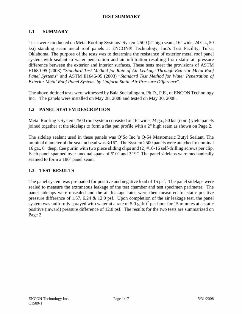
1.1 SUMMARY
Tests were conducted on Metal Roofing Systems’ System 2500 (2" high seam, 16" wide, 24 Ga., 50 ksi) standing seam metal roof panels at ENCON® Technology, Inc.'s Test Facility, Tulsa, Oklahoma. The purpose of the tests was to determine the resistance of exterior metal roof panel system with sealant to water penetration and air infiltration resulting from static air pressure difference between the exterior and interior surfaces. These tests meet the provisions of ASTM E1680-95 (2003) “Standard Test Method for Rate of Air Leakage Through Exterior Metal Roof Panel Systems” and ASTM E1646-95 (2003) “Standard Test Method for Water Penetration of Exterior Metal Roof Panel Systems by Uniform Static Air Pressure Difference”. The above-defined tests were witnessed by Bala Sockalingam, Ph.D., P.E., of ENCON Technology Inc. The panels were installed on May 28, 2008 and tested on May 30, 2008. 1.2 PANEL SYSTEM DESCRIPTION Metal Roofing’s System 2500 roof system consisted of 16" wide, 24 ga., 50 ksi (nom.) yield panels joined together at the sidelaps to form a flat pan profile with a 2" high seam as shown on Page 2. The sidelap sealant used in these panels was Q’So Inc.’s Q-54 Mastomeric Butyl Sealant. The nominal diameter of the sealant bead was 3/16". The System 2500 panels were attached to nominal 16 ga., 6" deep, Cee purlin with two piece sliding clips and (2) #10-16 self-drilling screws per clip. Each panel spanned over unequal spans of 5' 0" and 3’ 9”. The panel sidelaps were mechanically seamed to form a 180º panel seam. 1.3 TEST RESULTS The panel system was preloaded for positive and negative load of 15 psf. The panel sidelaps were sealed to measure the extraneous leakage of the test chamber and test specimen perimeter. The panel sidelaps were unsealed and the air leakage rates were then measured for static positive pressure difference of 1.57, 6.24 & 12.0 psf. Upon completion of the air leakage test, the panel system was uniformly sprayed with water at a rate of 5.0 gal/ft2 per hour for 15 minutes at a static positive (inward) pressure difference of 12.0 psf. The results for the two tests are summarized on Page 2.


DESCRIPTION OF TEST
ENCON Technology Inc. Page 4/17 5/31/2008 C1589-1
2.1 DESCRIPTION OF TEST
OBJECTIVES The purpose of the tests was to determine the resistance of metal roof panel systems to water penetration and air infiltration resulting from static air pressure difference between the exterior and interior surfaces. The test method consisted of the following: 1. assembling the test panel in the test chamber to form a typical roof construction; 2. measuring the air leakage through the panel sidelaps and extraneous leakage of the test
chambers; 3. spraying the exterior roof surface with water to determine any water penetration through
panel sidelaps TEST CHAMBER The test chamber consisted of a box as shown in the applicable drawings in Section V. It contains one open surface against which the test specimen was installed. One static pressure tap is located at a corner to measure the chamber pressure in such a manner that the reading was not affected by the velocity of the air supply to or from the chamber or other air movement. The air supply opening into the chamber was arranged so that the air does not impinge directly on the test specimen with significant velocity. AIR SYSTEM The compressed air supply consists of a compressor unit capable of maintaining a constant positive or negative air pressure difference for the required test period. A digital manometer was used to measure the test pressure difference with accuracy of 1/100." AIR FLOW METERING SYSTEM A laminar flow element capable of measuring airflow of 40 SCFM was used to measure the air leakage through the panel sidelaps and extraneous leakage of the test chambers. The flow was measured as a differential pressure using a digital manometer and converted to actual flow using regression equation shown on the flowmeter calibration chart. WATER SPRAY SYSTEM The water spray system consists of equally spaced nozzles located at a uniform distance from the test specimen. The system was calibrated to deliver a minimum rate of 5.0 gal/ft2 per hour. CALIBRATION The water spray was calibrated on April 24, 2008 and the air-flow measuring system was calibrated on February 13, 2008.

DESCRIPTION OF TEST
ENCON Technology Inc. Page 5/17 5/31/2008 C1589-1
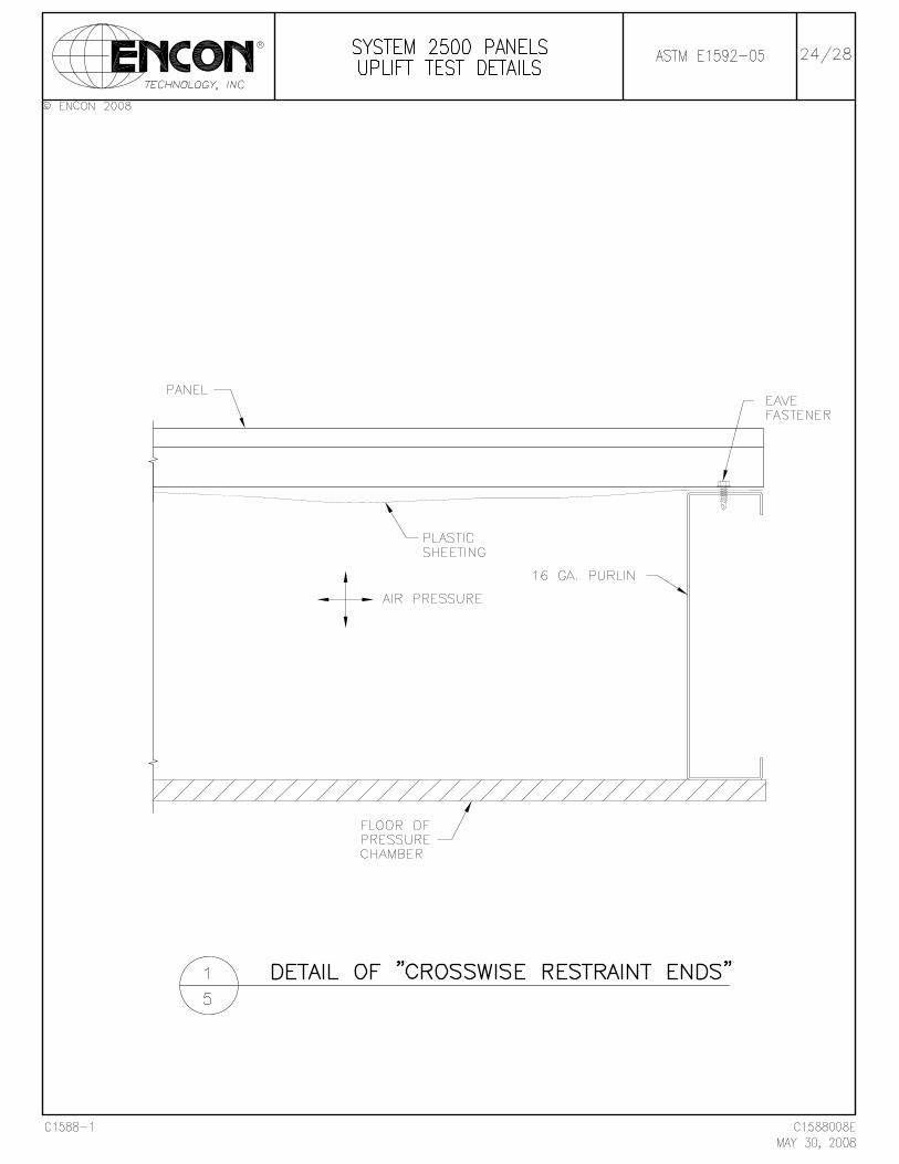
TEST SPECIMEN The overall dimension of the test construction was in excess of 7' 9" x 8' 9". The panels covered unequal spans of 5' 0" and 3' 9". The construction width contained four full panels and two partial panels. The panels were attached to an intermediate Cee purlin section with panel clips and (2) #10-16 self-drilling screws per clip. The panels were attached to 16 ga. eave, rake and ridge sections with self-drilling screws. An overflow device that provided a ½" to ¾" deep water pond was installed on one end of the test specimen. The perimeter of the test construction was sealed to the test chamber wall. The perimeter seals between the panels and the test chamber did not duplicate the actual building perimeter details. The details of the methods of construction are depicted in the enclosed test drawings in Section V. TEST PROCEDURE
The support beams were moved to 75% of the design thermal movement of the panel clip to the support. This operation was conducted once for a total of two cycles. All supports beam connections to the test chamber were tightened. The test specimen was preloaded to a positive load greater than or equal to 15 psf or 75% of the building live load or 50 % of the design positive wind pressure difference. The test specimen was also preloaded to a negative load greater than or equal to 50 % of the building design wind uplift pressure difference. The panel sidelap was temporarily sealed to measure the extraneous air leakage, QL, of the test chamber for the specified test pressure difference across the test specimen. The temporary sidelap seal was removed and the airflow through the sidelaps was measured after the test conditions were stabilized for the specified test pressure difference across the test specimen. This measured airflow was designated the total metered airflow, QM. The air leakage, Q, through the test specimen was equal to QM - QL. The ambient room temperature at the test specimen was also measured. Upon the completion of the air leakage test, the water spray system was installed over the test specimen. The test specimen was subjected to the specified positive (inward) test pressure difference for 15 minutes while the spray system delivered water on the test specimen at a rate of 5.0 gal/ft2 per hour. The depth and the temperature of the ponded water on the test surface were measured. The test specimen was observed for possible water leakage.

TEST RESULTS
ENCON Technology Inc. Page 6/17 5/31/2008 C1589-1
3.1 SPECIMEN IDENTIFICATION
Manufacturer: Metal Roofing Systems Model Type: System 2500 Panel Dimensions: 2" high seam, 16" wide flat pan profile with 180º seam Panel Gauge: 24 Clip Type: System 2500 two piece sliding clip Fasteners: (2) #10-16 SDS Purlin: 16 ga. (0.059" thick) Sealant Manufacturer: Q’So Inc. Panel Sealant: Q-54 Mastomeric Butyl Sealant Sealant Size: Nom. 3/16" bead Thermal Movement: ±0.625" Note: All the test materials were supplied by Metal Roofing Systems and were not sampled by ENCON.

TEST RESULTS
ENCON Technology Inc. Page 7/17 5/31/2008 C1589-1
3.2 TEST DATA
Date: 5.30.2008Panel Manufacturer Metal Roofing SystemsPanel Type System 2500Panel Gauge 24Panel Width (in) 16Panel Attachment System 2500 Clip with (2) #10-16 SDSSealant Manufacturer Q'So Inc.Panel Sealant Q-54 Mastomeric Butyl Sealant (Nom. 3/16" Bead)Panel Span (ft) 5' 0" - 3' 9"Test Area (ft2) 67.8Preload Positive Pressure (psf) 15Preload Negative Pressure (psf) 15Ambient Temperature (F) 78.8Panel Temperature (F) 78.2Barometric Pressure (in. Hg) 29.15Water Depth (in) 0.625
Test Method: ASTM E1680-95 (2003)Test Static Pressure Initial Initial Final Final Total Air Air InfiltrationNo. Difference Reading Reading 1 Reading Reading 1 Leakage 2 Rate
psf DP (in) cfm DP (in) cfm cfm cfm/ft2 cfm/lin.ft1 1.57 0.861 4.411 0.867 4.442 0.0300 0.0004 0.00062 6.24 2.251 11.501 2.261 11.552 0.0497 0.0007 0.00103 12.00 3.456 17.615 3.472 17.696 0.0792 0.0012 0.0016
1 The actual flow is calculated using the regression equation shown on the flowmeter calibration chart.2 Total Air Leakage Qst = Q x (1.326 x B / (0.075 x (T + 460)))0.5
Test Method: ASTM E1646-95 (2003)Test Static Pressure Rate Test Water Infiltration No. Difference (gal/hr/ft2) Duration
psf (min)1 12 5 15 No Water Leakage


APPENDIX
ENCON Technology Inc. Page 16/17 5/31/2008 C1589-1
5.3 TEST CONDITIONS
A. OWNERSHIP OF ENCON WORK PRODUCT
All test results developed as a part of this work shall be CUSTOMER's property. All samples submitted to ENCON for testing shall become the property of ENCON. CUSTOMER understands that any test program including procedures and test machines incorporated as a part of this work is a result of continuing long-term research and development by ENCON and because of this all ENCON test procedures, test drawings and other intellectual property relating to this work is and shall remain the property of ENCON. Test samples were disposed of shortly after completion of the tests unless other arrangements were agreed to in writing prior to the test. ENCON will use its normal procedures to retain copies of the information developed as a part of this test for a period of three years from the date the work was done. This material may be routinely destroyed thereafter.
B. ENCON GUARANTEE
ENCON guarantees it used its best effort to accomplish this test work. Work done by ENCON was carefully completed by personnel believed to be competent. ENCON tests were based on what was currently believed to be good engineering practices in use at the time of the test. The safety factors used are generally accepted as suitable to produce safe results. However, good engineering practices and applicable codes and insurance requirements must be taken into consideration in determining if a test procedure is satisfactory for a specific end use. Applicable specifications, good engineering practices and applicable safety factors may change in the future. CUSTOMER should be alert to these changes. The information and test results presented by ENCON in this test report are offered in good faith based on information ENCON believes to be reliable. This information is offered as a guide to assist CUSTOMER in CUSTOMER's endeavors and does not contain any warranties as to fitness by ENCON. No REPRESENTATION OF WARRANTIES, EXPRESS OR IMPLIED, INCLUDING THOSE OF MERCHANTABILITY AND OF FITNESS FOR A PARTICULAR PURPOSE are made by ENCON, and more specifically, ENCON hereby expressly disclaim such. In no event shall ENCON be liable for ANY CONSEQUENTIAL, INCIDENTAL OR SPECIAL DAMAGES, including, without limitation, labor, transportation, loss of use, loss of profits, harm, personnel injury and damage to property. If any doubt exists as to the proper means of interpreting or using the test results contained herein, contact ENCON for clarification. CUSTOMER should assure themselves through careful evaluations that test results are suitable for those end uses to which CUSTOMER intends to put them.

APPENDIX
ENCON Technology Inc. Page 17/17 5/31/2008 C1589-1
Information and material provided by CUSTOMER to ENCON was reviewed by an ENCON executive. However, ENCON does not accept the responsibility for accuracy or verification of CUSTOMER's information or the suitability of CUSTOMER materials. Materials supplied by CUSTOMER were tested as received and were not evaluated for code or insurance compliance. CUSTOMER is expected to review the ENCON drawings, tables, test results and other information provided by ENCON to CUSTOMER critically so as to assure CUSTOMER that these presentations, formulas, drawings and other information are accurate and meaningful for the purpose intended. No other warranties or guarantees shall be issued, implied, delivered or otherwise construed to be issued, implied or delivered.
ENCON® TECHNOLOGY, INC., 2008