TEST REPORT ON CENTRAL STATES …€¦ · · 2018-03-27The test setup consisted of an exterior...
22
TL-327 TEST REPORT ON CENTRAL STATES MANUFACTURING, INC.’S PANEL-LOC PLUS PANELS (26 GA., 80 KSI, 36" WIDE) FASTENED TO WOOD SUPPORTS AT 2' 0" PANEL SPANS IN ACCORDANCE WITH ASTM E455-11 AND AISI S907-08 TESTED FOR: Central States Manufacturing, Inc. 302 Jane Place Lowell, AR 72745 Telephone: (800) 356-2733 Fax: (800) 356-2971 TESTED BY: ENCON ® Technology, Inc. 1216 North Lansing Avenue, Suite C Tulsa, OK 74106 Telephone: (918) 492-5992 FAX: (866) 366-1543 TEST WITNESSED BY: Bala Sockalingam, Ph.D., P.E. TESTING DATE: December 14, 2012 REPORTING DATE: December 20, 2012 ENCON® Project C1872-2
-
Upload
vuongnguyet -
Category
Documents
-
view
213 -
download
0
Transcript of TEST REPORT ON CENTRAL STATES …€¦ · · 2018-03-27The test setup consisted of an exterior...

TL-327
TEST REPORT ON
CENTRAL STATES MANUFACTURING, INC.’S PANEL-LOC PLUS PANELS (26 GA., 80 KSI, 36" WIDE)
FASTENED TO WOOD SUPPORTS AT 2' 0" PANEL SPANS
IN ACCORDANCE WITH ASTM E455-11 AND AISI S907-08
TESTED FOR: Central States Manufacturing, Inc.
302 Jane Place Lowell, AR 72745
Telephone: (800) 356-2733 Fax: (800) 356-2971
TESTED BY: ENCON® Technology, Inc.
1216 North Lansing Avenue, Suite C Tulsa, OK 74106
Telephone: (918) 492-5992 FAX: (866) 366-1543
TEST WITNESSED BY: Bala Sockalingam, Ph.D., P.E.
TESTING DATE: December 14, 2012 REPORTING DATE: December 20, 2012
ENCON® Project C1872-2

ENCON Technology Inc. 12/20/2012 C1872-2
TABLE OF CONTENTS
SECTION I TEST SUMMARY Page Number 1.1 Summary 1 1.2 Panel System Description 1 1.3 Test Results 1 1.4 Panel and Fastener Pattern Drawing 2 SECTION II DESCRIPTION OF TEST 2.1 Description of Test 3-4 2.2 Calculations 4-5
SECTION III TEST RESULTS 3.1 Specimen Identification 6 3.2 Test #1: Panel-Loc Plus Panels at four equal span of 2' 0" 7-8 3.3 Test #2: Panel-Loc Plus Panels at four equal span of 2' 0" 9-10 SECTION IV TEST PHOTOGRAPHS 4.1 Test Photographs 11-13 SECTION V APPENDIX
5.1 Test Drawings 14-17 5.2 Yield Stress 18 5.3 Test Conditions 19-20

TEST SUMMARY
ENCON Technology Inc. Page 1/20 12/20/2012 C1872-2 Revised: 1/30/2013
1.1 SUMMARY
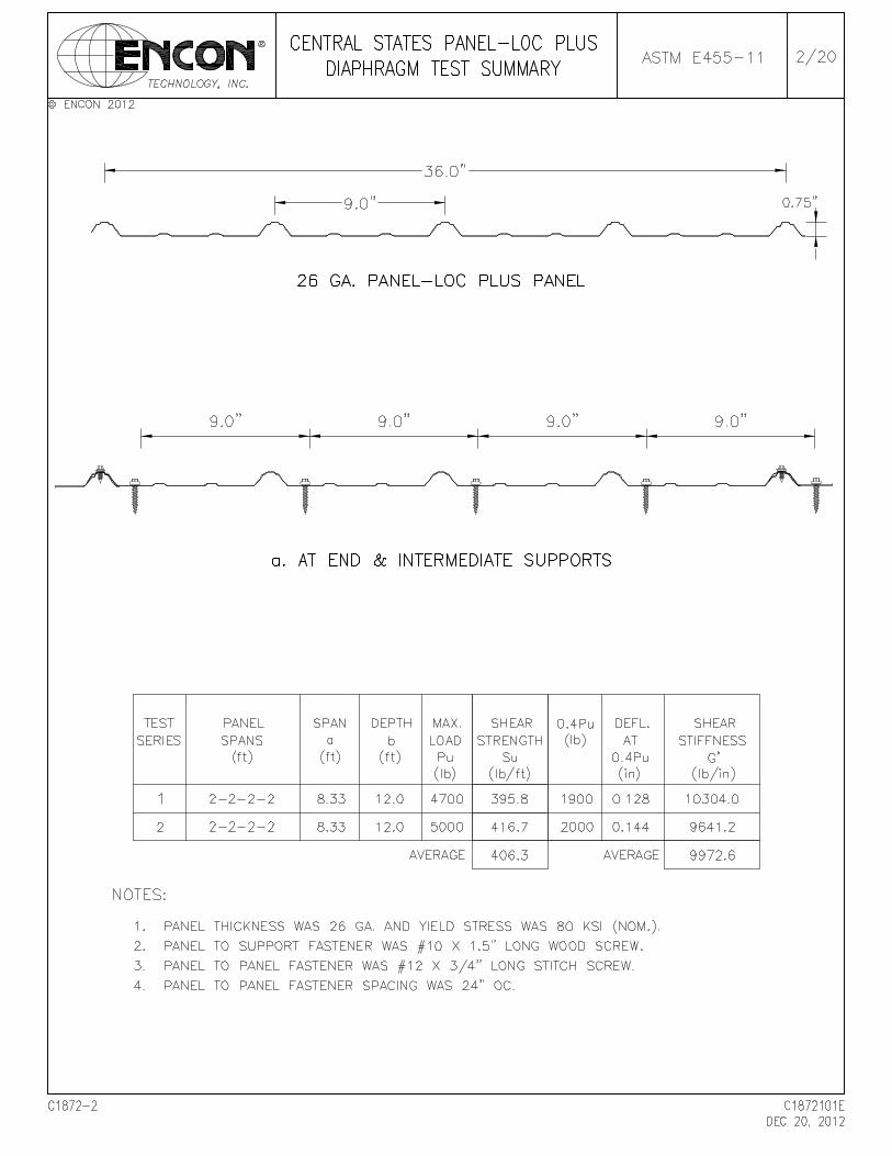
Tests were conducted on Central States Manufacturing, Inc.’s 26 ga., 80 ksi Panel-Loc Plus panels at ENCON® Technology, Inc.’s Test Facility, Tulsa, Oklahoma. The purpose of the tests was to determine the diaphragm shear strength and shear stiffness of Panel-Loc Plus panel construction under simulated loading conditions. These tests meet the provisions of ASTM E455-011 and AISI S907-08. The tests are listed below according to date tested. Test #1 & 2: Panel-Loc Plus panels at four equal spans of 2' 0". The structural fastener spacing
was 9" o.c. at the end and interior wood supports. Both tests were conducted on December 14, 2012.
The sidelap fasteners spacing for both tests was 24" o.c. The above-defined tests were witnessed by Bala Sockalingam, Ph.D., P.E. of ENCON Technology, Inc. 1.2 PANEL SYSTEM DESCRIPTION Central States Mfg.’s Panel-Loc Plus panels were 26 ga., 3/4" high and 36" wide through fastened panels. Each panel consisted of five major ribs spaced at 9" o.c. as shown on Page 2. The panels were fastened to nominal 2" x 6" SPF wood supports with #10 x 1-1/2" long Kwikseal® II Wood Binder screws with washers. The screw spacing was 9" o.c. at the end and interior wood supports. Each panel spanned over four continuous spans of 2' 0" with 2" overhang. The sidelap fasteners were #12 x 3/4" long hex head stitch screws with washers and spaced at 24" o.c. The two sides of the panel assembly were not attached to the side post of the interior frame. 1.3 TEST RESULTS Load was applied incrementally and deflections of the test construction were recorded for ‘no load’ condition and at each load increment. The failure mode in Test #1 was the panel slotting at the fastener near the loaded corner and in Test #2 was the fastener tilting along with panel slotting at the fastener near the loaded corner. The average ultimate shear strength from the two test constructions was 406.3 lb/ft and average shear stiffness was 9972.6 lb/in.
DESCRIPTION OF TEST
ENCON Technology Inc. Page 3/20 12/20/2012 C1872-2
2.1 DESCRIPTION OF TEST
OBJECTIVES Tests were conducted to determine shear strength and shear stiffness of the panels under simulated loading conditions. The test method consisted of the following: 1. assembling the test panel on an interior test frame to form a typical roof or wall
construction; 2. loading the test frame incrementally; and 3. observing, measuring, and recording the deflections, deformations, and nature of any
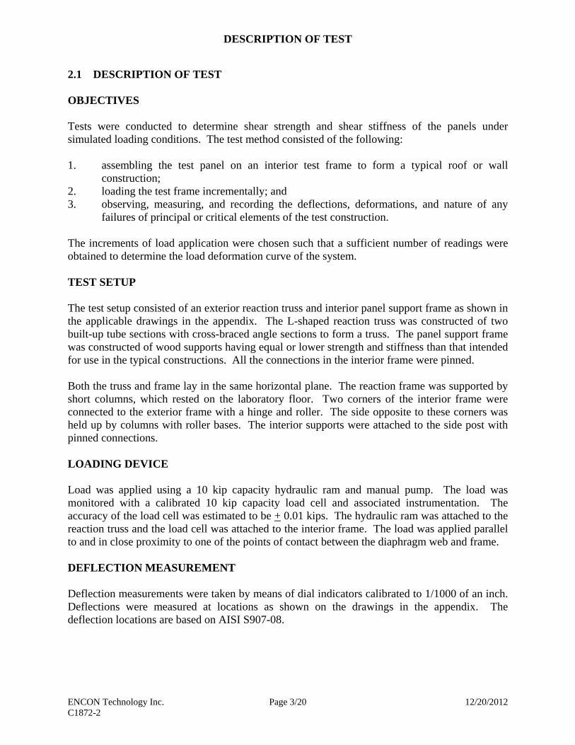
failures of principal or critical elements of the test construction. The increments of load application were chosen such that a sufficient number of readings were obtained to determine the load deformation curve of the system. TEST SETUP The test setup consisted of an exterior reaction truss and interior panel support frame as shown in the applicable drawings in the appendix. The L-shaped reaction truss was constructed of two built-up tube sections with cross-braced angle sections to form a truss. The panel support frame was constructed of wood supports having equal or lower strength and stiffness than that intended for use in the typical constructions. All the connections in the interior frame were pinned. Both the truss and frame lay in the same horizontal plane. The reaction frame was supported by short columns, which rested on the laboratory floor. Two corners of the interior frame were connected to the exterior frame with a hinge and roller. The side opposite to these corners was held up by columns with roller bases. The interior supports were attached to the side post with pinned connections. LOADING DEVICE Load was applied using a 10 kip capacity hydraulic ram and manual pump. The load was monitored with a calibrated 10 kip capacity load cell and associated instrumentation. The accuracy of the load cell was estimated to be + 0.01 kips. The hydraulic ram was attached to the reaction truss and the load cell was attached to the interior frame. The load was applied parallel to and in close proximity to one of the points of contact between the diaphragm web and frame. DEFLECTION MEASUREMENT Deflection measurements were taken by means of dial indicators calibrated to 1/1000 of an inch. Deflections were measured at locations as shown on the drawings in the appendix. The deflection locations are based on AISI S907-08.

DESCRIPTION OF TEST
ENCON Technology Inc. Page 4/20 12/20/2012 C1872-2
DIAPHRAGM SIZE The overall dimension of each construction was in excess of 12' x 8' 4". The panels covered four equal spans of 2' 0". The construction width contained four full panels. The panels were attached to the end and interior wood supports with self-drilling screws. The panels were not attached to the side member of the interior frame. The details of the methods of construction are depicted in the enclosed test drawings. All the material used in the construction represented a typical construction. NUMBER OF TESTS Minimum of two panel assemblies was tested to determine the value of a given construction. TEST PROCEDURE Prior to the diaphragm construction, the interior frame was loaded to determine its bare frame stiffness. The bare frame stiffness was insignificant, deflecting 1" under a 10-lb load. The loading procedure on the completed diaphragm construction consisted of loads applied in increments. The diaphragm was loaded to 20% of the anticipated ultimate load and unloaded. Deflection measurements were recorded at ‘no load’ conditions. The diaphragm was loaded in 250-lb increments until failure. Deflection measurements were recorded at every load increment. TEST DURATION The test was stopped when the test specimen was unable to carry additional load or visual failure of one or more components of the diaphragm occurred. 2.2 CALCULATIONS The ultimate shear strength Su (lb/ft) of a given construction is where
Pu = maximum applied load in the cantilever beam test (lb), b = depth of diaphragm (ft). The net shear deflections () at any load level in the cantilever beam test is
where 1,2,3 and 4 are measured deformations with appropriate signs at locations shown in the test drawings.
b
PS u
u
41b
a23

DESCRIPTION OF TEST
ENCON Technology Inc. Page 5/20 12/20/2012 C1872-2
The apparent shear stiffness G’ (lb/in) of a given construction is where
P = 0.4Pu in the cantilever beam test (lb), a = span of diaphragm (ft). = Net shear deflection of diaphragm (in) at 0.4Pu load. The shear stiffness calculation is based on AISI S907-08.
b
aPG

TEST RESULTS
ENCON Technology Inc. Page 6/20 12/20/2012 C1872-2
3.1 SPECIMEN IDENTIFICATION
Manufacturer: Central States Manufacturing, Inc Model Type: Panel-Loc Plus Panel Dimensions: 0.75" high, 36" wide coverage Panel Thickness: 26 ga. Base Metal Thickness: 0.018" Panel Yield Stress: 80 ksi (94.5 ksi tested) Panel Fasteners: #10 x 1.5" long hex head wood screws with washers (Sealtite
Building Fasteners Kwikseal® II Wood Binder) Panel Fasteners Spacing: 9" o.c. Support Thickness: Nom. 2" x 6" SPF Sidelap Fasteners: #12 x 3/4" long hex head stitch screws with washers (Sealtite
Building Fasteners) Sidelap Fasteners Spacing: 24" o.c. Note: All the test materials were supplied by or purchased for Central States
Manufacturing and were not sampled by ENCON.

TEST RESULTS
ENCON Technology Inc. Page 7/20 12/20/2012 C1872-2
3.2 TEST #1: 26 GA. PANEL-LOC PLUS AT FOUR EQUAL SPAN OF 2' 0" Date: 12.14.12Panel Type: Panel-Loc PlusGauge: 26 ga.Thickness: 0.018"Panel Width: 36"Support Spacing: 4 spans @ 24" o.c.Type of Structural Fastener: #10 x 1.5" long Kwikseal II screwsFastener Spacing at End Supports: 9" o.c.Fastener Spacing at Interior Supports: 9" o.c.Insulation NoneType of Sidelap Fastener: #12 x 3/4" long stitch screwsSidelap Fastener Spacing 24" o.ca = span length of diaphragm (ft): 8.33b = depth of diaphragm (ft): 12.00
Load Dial Indicator Reading (in) Shear (lb) Deformation
1 2 3 4 (in)0 0.000 0.000 0.000 0.000 0.000
250 0.012 0.001 0.043 0.021 0.019500 0.028 0.009 0.102 0.051 0.038750 0.038 0.018 0.150 0.075 0.054
1000 0.053 0.028 0.201 0.100 0.0671250 0.062 0.033 0.250 0.124 0.0881500 0.066 0.043 0.288 0.142 0.1011750 0.074 0.053 0.331 0.161 0.1152000 0.080 0.058 0.376 0.181 0.1372250 0.084 0.067 0.420 0.203 0.1542500 0.099 0.080 0.473 0.221 0.1712750 0.106 0.080 0.517 0.240 0.1973000 0.112 0.087 0.575 0.260 0.2303250 0.118 0.087 0.630 0.280 0.2673500 0.126 0.089 0.689 0.296 0.3073750 0.134 0.092 0.765 0.321 0.3574000 0.147 0.093 0.846 0.334 0.4194250 0.154 0.097 0.945 0.347 0.5004500 0.180 0.113 1.120 0.377 0.6204750 0.212 0.115 1.279 0.409 0.733
Failure Mode: Panel slotting at the fastener near loaded cornerDuration of test: > 10 minutes
Temperature (F) Relative Humidity (%)At construction: 64.4 31At testing 64.4 31

TEST RESULTS
ENCON Technology Inc. Page 8/20 12/20/2012 C1872-2
0
500
1000
1500
2000
2500
3000
3500
4000
4500
5000
0.000 0.200 0.400 0.600 0.800
Loa
d (
lbs)
Deflections (in)
Load vs Deflection (Test #1)

TEST RESULTS
ENCON Technology Inc. Page 9/20 12/20/2012 C1872-2
3.3 TEST #2: 26 GA., 80 KSI PANEL-LOC PLUS AT FOUR EQUAL SPAN OF 2' 0" Date: 12.14.12Panel Type: Panel-Loc PlusGauge: 26 ga.Thickness: 0.018"Panel Width: 36"Support Spacing: 4 spans @ 24" o.c.Type of Structural Fastener: #10 x 1.5" long Kwikseal II screwsFastener Spacing at End Supports: 9" o.c.Fastener Spacing at Interior Supports: 9" o.c.Insulation NoneType of Sidelap Fastener: #12 x 3/4" long stitch screwsSidelap Fastener Spacing 24" o.ca = span length of diaphragm (ft): 8.33b = depth of diaphragm (ft): 12.00
Load Dial Indicator Reading (in) Shear (lb) Deformation
1 2 3 4 (in)0 0.000 0.000 0.000 0.000 0.000
250 0.009 0.001 0.032 0.014 0.015500 0.024 0.001 0.070 0.035 0.028750 0.044 0.001 0.114 0.056 0.044
1000 0.053 0.005 0.159 0.080 0.0621250 0.063 0.011 0.212 0.105 0.0841500 0.073 0.021 0.265 0.126 0.1061750 0.087 0.030 0.309 0.144 0.1192000 0.095 0.038 0.361 0.163 0.1442250 0.103 0.042 0.416 0.183 0.1752500 0.127 0.055 0.474 0.195 0.1952750 0.146 0.060 0.547 0.246 0.2153000 0.159 0.065 0.619 0.264 0.2603250 0.169 0.065 0.684 0.278 0.3093500 0.179 0.067 0.750 0.302 0.3493750 0.187 0.070 0.819 0.315 0.4014000 0.196 0.071 0.899 0.327 0.4654250 0.207 0.075 1.004 0.357 0.5374500 0.225 0.080 1.179 0.376 0.6824750 0.245 0.085 1.365 0.393 0.8375000
Failure Mode: Panel tilting & slotting at the fastener near loaded cornerDuration of test: > 10 minutes
Temperature (F) Relative Humidity (%)At construction: 64.4 31At testing 64.4 31

TEST RESULTS
ENCON Technology Inc. Page 10/20 12/20/2012 C1872-2
0
500
1000
1500
2000
2500
3000
3500
4000
4500
5000
0.000 0.200 0.400 0.600 0.800 1.000
Loa
d (
lbs)
Deflections (in)
Load vs Deflection (Test #2)

PHOTOGRAPHS
ENCON Technology Inc. Page 11/20 12/20/2012 C1872-2
PHOTO 1 View of the structural and sidelap fasteners. (DSCN1011)
PHOTO 2 View of the wood support layout. (DSCN1040)

PHOTOGRAPHS
ENCON Technology Inc. Page 12/20 12/20/2012 C1872-2
PHOTO 3 View of the panel fasteners at end and interior supports. (DSCN1012)
PHOTO 4 Overview of the diaphragm test setup of the Panel-Loc Plus panels. (DSCN1013)

PHOTOGRAPHS
ENCON Technology Inc. Page 13/20 12/20/2012 C1872-2
PHOTO 5 View of panel slotting at fastener near the pinned support in Test #1. (DSCN1017)
PHOTO 6 View of fastener tilting and panel slotting at the fastener near the loaded corner in
Test #2. (DSCN1021)


SteelMaterial:
Description: (2) Central State Mfg. Test Samples
Room Temperature Tensile Testing ASTM E8/E8M-11, Parallel to Length of the Specimen, As Received
Sample ID Width, Initial,in
Thickness, Initial,in
Tensile Strength,psi
Yield (0.2%Offset),
psi
Elongation(4W),
%
Location of Fracture
R-Loc, Sample No.:13 0.502 0.017 106400 2
Outside Middle Half ofGage
Specimen broke with extensometer.
Room Temperature Tensile Testing ASTM E8/E8M-11, Parallel to Length of the Specimen, As Received
Sample ID Width, Initial,in
Thickness, Initial,in
Tensile Strength,psi
Yield (0.2%Offset),
psi
Elongation(4W),
%
Location of Fracture
Panel-Loc Plus,Sample No.: 14 0.504 0.018 95600 94500 4
Inside Middle Half ofGage
Approved by:
Jason Pierce
Materials Testing Supervisor
Western Materials, SEG, & Nonmetallics3100 North Hemlock CircleBroken Arrow, OK 74012-1115
LABORATORY REPORT
Attn:
ENCON Technology, Inc.1216 N. Lansing Ave.
Suite C
Report No:
Date Reported:
P.O. No:
12/19/2012
Verbal
Report No: B12120915Bala Sockalingam
Tulsa, OK 74106 United States
Tel: 918-258-6066800-982-8378
Fax: 918-258-1154
Test results relate only to the items tested. This document shall not be reproduced, except in full, without the written approval of Sherry Laboratories, Inc. The recording of false, fictitious, or fraudulent statements or entries on this document may be a punishable offense under federal and state law. A2LA Accredited Laboratory Certificate No. 1089-01 (Mechanical) & 1089-02 (Chemical).
Page 1 of 1

APPENDIX
ENCON Technology Inc. Page 19/20 12/20/2012 C1872-2
5.3 TEST CONDITIONS
A. OWNERSHIP OF ENCON WORK PRODUCT
All test results developed as a part of this work shall be CUSTOMER's property. All samples submitted to ENCON for testing shall become the property of ENCON. CUSTOMER understands that any test program including procedures and test machines incorporated as a part of this work is a result of continuing long-term research and development by ENCON and because of this all ENCON test procedures, test drawings and other intellectual property relating to this work is and shall remain the property of ENCON. Test samples were disposed of shortly after completion of the tests unless other arrangements were agreed to in writing prior to the test. ENCON will use its normal procedures to retain copies of the information developed as a part of this test for a period of three years from the date the work was done. This material may be routinely destroyed thereafter.
B. ENCON GUARANTEE
ENCON guarantees it used its best effort to accomplish this test work. Work done by ENCON was carefully completed by personnel believed to be competent. ENCON tests were based on what was currently believed to be good engineering practices in use at the time of the test. The safety factors used are generally accepted as suitable to produce safe results. However, good engineering practices and applicable codes and insurance requirements must be taken into consideration in determining if a test procedure is satisfactory for a specific end use. Applicable specifications, good engineering practices and applicable safety factors may change in the future. CUSTOMER should be alert to these changes. The information and test results presented by ENCON in this test report are offered in good faith based on information ENCON believes to be reliable. This information is offered as a guide to assist CUSTOMER in CUSTOMER's endeavors and does not contain any warranties as to fitness by ENCON. No REPRESENTATION OF WARRANTIES, EXPRESS OR IMPLIED, INCLUDING THOSE OF MERCHANTABILITY AND OF FITNESS FOR A PARTICULAR PURPOSE are made by ENCON, and more specifically, ENCON hereby expressly disclaim such. In no event shall ENCON be liable for ANY CONSEQUENTIAL, INCIDENTAL OR SPECIAL DAMAGES, including, without limitation, labor, transportation, loss of use, loss of profits, harm, personnel injury and damage to property. If any doubt exists as to the proper means of interpreting or using the test results contained herein, contact ENCON for clarification. CUSTOMER should assure themselves through careful evaluations that test results are suitable for those end uses to which CUSTOMER intends to put them.
APPENDIX
ENCON Technology Inc. Page 20/20 12/20/2012 C1872-2
Information and material provided by CUSTOMER to ENCON was reviewed by an ENCON executive. However, ENCON does not accept the responsibility for accuracy or verification of CUSTOMER's information or the suitability of CUSTOMER materials. Materials supplied by CUSTOMER were tested as received and were not evaluated for code or insurance compliance. CUSTOMER is expected to review the ENCON drawings, tables, test results and other information provided by ENCON to CUSTOMER critically so as to assure CUSTOMER that these presentations, formulas, drawings and other information are accurate and meaningful for the purpose intended. No other warranties or guarantees shall be issued, implied, delivered or otherwise construed to be issued, implied or delivered.
ENCON® TECHNOLOGY, INC., 2012