TEST REPORT IEC 60 898-1:2002 Circuit-Breakers for ... · Page 10 of 92 R e port ref. No.:...
92
Page 1 of 92 R e port ref. No.: C009-CB2012CQC-044407 TRF No.: IEC60898_1B TRF originator: KEMA Test Report issued under the responsibility of: TEST REPORT IEC 60 898-1:2002 Circuit-Breakers for overcorrect protection for household and similar installation Report reference No . ..................... : C009-CB2012CQC-044407 Tested by (printed name and signature) ........................................ : Wang Yingchao ..................................................... Approved by (printed name and signature) ........................................ : Yi Ying ..................................................... Date of issue ................................... : 2012-12-5 Testing Laboratory Name ............. : Shanghai Testing & Inspection Institute for Electrical Equipment (STIEE) Address ........................................... : 505 Wu Ning Road Shanghai P. R. China Testing location /procedure ............. : CBTL TMP WMT SMT Applicant‟s Name ............................ : Zhejiang Denrom Electric Equipment Co., Ltd Address ........................................... : No.12 Huifeng Road,Yueqing City, Zhejiang Province,P.R.China Test specification Standard ........................................... : IEC 60 898:-1:2002 + Amendment 1:2002 Test procedure ................................ : CB Procedure deviation ........................ : N/A Non-standard test method ............... : N/A Test Report Form Test Report Form No. ...................... : IEC60898_1B TRF originator . ................................ : KEMA Master TRF ..................................... : dated 2004-02 Copyright 2002 IEC System for Conformity Testing and Certification of Electrical Equipment (IECEE), Geneva, Switzerland. All rights reserved. This publication may be reproduced in whole or in part for non-commercial purposes as long as the IECEE is acknowledged as copyright owner and source of the material. IECEE takes no responsibility for and will not assume liability for damages resulting from the reader‟s interpretation of the reproduced material due to its placement and context.). Test item description .................... : MCB‟s Trademark ....................................... : DL Manufacturer Zhejiang Denrom Electric Equipment Co., Ltd No.12 Huifeng Road,Yueqing City, Zhejiang Province,P.R.China
Transcript of TEST REPORT IEC 60 898-1:2002 Circuit-Breakers for ... · Page 10 of 92 R e port ref. No.:...
Page 1 of 92 R e port ref. No.: C009-CB2012CQC-044407
TRF No.: IEC60898_1B TRF originator: KEMA
Test Report issued under the responsibility of:
TEST REPORT
IEC 60 898-1:2002
Circuit-Breakers for overcorrect protection for
household and similar installation
Report reference No . ..................... : C009-CB2012CQC-044407
Tested by (printed name and signature) ........................................ : Wang Yingchao
.....................................................
Approved by (printed name and signature) ........................................ : Yi Ying
.....................................................
Date of issue ................................... : 2012-12-5
Testing Laboratory Name ............. : Shanghai Testing & Inspection Institute for Electrical Equipment (STIEE)
Address ........................................... : 505 Wu Ning Road Shanghai P. R. China
Testing location /procedure ............. : CBTL TMP WMT SMT
Applicant‟s Name ............................ : Zhejiang Denrom Electric Equipment Co., Ltd
Address ........................................... : No.12 Huifeng Road,Yueqing City, Zhejiang Province,P.R.China
Test specification
Standard ........................................... : IEC 60 898:-1:2002 + Amendment 1:2002
Test procedure ................................ : CB
Procedure deviation ........................ : N/A
Non-standard test method ............... : N/A
Test Report Form
Test Report Form No. ...................... : IEC60898_1B
TRF originator . ................................ : KEMA
Master TRF ..................................... : dated 2004-02
Copyright 2002 IEC System for Conformity Testing and Certification of Electrical Equipment (IECEE),
Geneva, Switzerland. All rights reserved.
This publication may be reproduced in whole or in part for non-commercial purposes as long as the IECEE is acknowledged as copyright owner and source of the material. IECEE takes no responsibility for and will not assume liability for damages resulting from the reader‟s interpretation of the reproduced material due to its placement and context.).
Test item description .................... : MCB‟s
Trademark ....................................... : DL
Manufacturer Zhejiang Denrom Electric Equipment Co., Ltd
No.12 Huifeng Road,Yueqing City, Zhejiang Province,P.R.China

Page 2 of 92 R e port ref. No.: C009-CB2012CQC-044407
TRF No.: IEC60898_1B TRF originator: KEMA
Series .............................................. : DL7
Model and/or type reference ........... : DL7
Rating(s) ........................................... : AC 240/415V; 6~63A

Page 3 of 92 R e port ref. No.: C009-CB2012CQC-044407
TRF No.: IEC60898_1B TRF originator: KEMA
Test items particulars:
Type of circuit-breaker .................................. : DL7
Number of poles ............................................ : 1P, 2P, 3P, 3P+N
Protection against external influences ........... : Unenclosed
Method of mounting ....................................... : Distribution board
Method of connection .................................... : Are not associated with the mechanical mounting
Instantaneous tripping current ....................... : C
Ambient air temperature (C) ........................ : 30
Energy limiting class ...................................... : --
Rated short-circuit capacity (A) ..................... : 10kA
Type of terminal ............................................. : Pillar terminals
Value of rated operational voltage ................. : AC 240/415V(1P), AC 415V(2P, 3P, 3P+N)
Value of rated current .................................... : 6A, 10A, 16A, 20A, 25A, 32A, 40A, 50A, 63A
Value of rated frequency ............................... : 50Hz
Test case verdicts
Test case does not apply to the test object ... : N/A
Test item does meet the requirement ........... : P(ass)
Test item does not meet the requirement ..... : F(ail)
Testing
Date of receipt of test item ............................ : 2012-09
Date(s) of performance of test ...................... : 2012-11
General remarks
This report is not valid as a CB Test Report unless signed by an approved CB Testing Laboratory and
appended to a CB Test Certificate issued by an NCB in accordance with IECEE 02.
The test results presented in this report relate only to the object tested. This report shall not be reproduced, except in full, without the written approval of the Issuing testing laboratory.
“(see Enclosure #)” refers to additional information appended to the report. ”(see appended table)” refers to a table appended to the report. Throughout this report a comma (point) is used as the decimal separator.
General product information
Type: DL7 Number of poles: 1P, 2P, 3P, 3P+N Rated operational voltage: AC 240/415V(1P), AC 415V(2P,3P, 3P+N) Rated current: 6A, 10A, 16A, 20A, 25A, 32A, 40A, 50A, 63A Instantaneous tripping current: C Rated short-circuit capacity: 10kA Grid distance: 50mm

Page 4 of 92 R e port ref. No.: C009-CB2012CQC-044407
TRF No.: IEC60898_1B TRF originator: KEMA
Pictures of product (1P)

Page 5 of 92 R e port ref. No.: C009-CB2012CQC-044407
TRF No.: IEC60898_1B TRF originator: KEMA
Pictures of product (2P)

Page 6 of 92 R e port ref. No.: C009-CB2012CQC-044407
TRF No.: IEC60898_1B TRF originator: KEMA
Pictures of product (3P+N)

Page 7 of 92 R e port ref. No.: C009-CB2012CQC-044407
TRF No.: IEC60898_1B TRF originator: KEMA
Pictures of product (3P+N)

Page 8 of 92 R e port ref. No.: C009-CB2012CQC-044407
TRF No.: IEC60898_1B TRF originator: KEMA
Pictures of product (Interior structure)

Page 9 of 92 R e port ref. No.: C009-CB2012CQC-044407
TRF No.: IEC60898_1B TRF originator: KEMA
Remark:/
List of Attachments (including a total number of pages in each attachment): /
Summary of test results:
Type Characteristics Number of
poles Rated current
Test sequence
DL7 C 1P 63A E1, E2
DL7 C 1P 6A E1, E2
DL7 C 2P 63A E1, E2
DL7 C 2P 6A E1, E2
DL7 C 3P+N 63A E1, E2
DL7 C 3P+N 6A E1, E2
DL7 C 1P 63A A, B, C1, C2, D0+D1,
DL7 C 1P 6A D0,
DL7 C 1P 10A D0
DL7 C 1P 16A D0
DL7 C 1P 20A D0
DL7 C 1P 25A D0
DL7 C 1P 32A D0
DL7 C 1P 40A D0
DL7 C 1P 50A D0
DL7 C 2P 63A C2,
DL7 C 3P+N 63A A, B, C1, C2, D0+D1,

Page 10 of 92 R e port ref. No.: C009-CB2012CQC-044407
TRF No.: IEC60898_1B TRF originator: KEMA
IEC 60 898
Cl. Requirement – Test Result Verdict
6 MARKING AND OTHER INFORMATION (DL7 C63 1P)
Circuit-breaker marked with:
a) Manufacturer‟s name or trade mark ................ : DENROM P
b)Type designation, catalogue number or other identification number ....................................... :
DL7-63/1/C P
c) Rated voltage (V) ............................................ : 240/415 P
d) Rated current (A) ............................................. : 63 P
e) Rated frequency (Hz) ...................................... : N/A
f) Rated short circuit capacity (A) ....................... : 10000 P
g) Wiring diagram N/A
h) Ambient air temperature, if different from 30°C N/A
i) Degree of protection, if different from IP20 N/A
j) For D-type circuit-breakers: the maximum instantaneous tripping current, if higher than 20 In(see table 2)
N/A
k) Rated impulse withstand voltage Uimp if it is 2,5 kV
N/A
Symbol for instantaneous tripping current C P
Symbol for nature of supply N/A
Marking for rated current and for instantaneous tripping shall be readily visible when CB is installed
P
Other marking shall be easily discernible P
The suitability for isolation, which is provided by all circuit-breakers of this standard, may be indicated by the symbol on the device
P
Energy limiting class N/A
I2t characteristic (documentation) N/A
Symbols on supply and load terminal P
Terminal for neutral conductor N N/A
Earthing terminal if any (IEC 60417-5019) N/A
On – off position shall be clearly indicated – 0 I - P
For push-button CB the off push-button shall either be red or be marked with the symbol 0́ ́
N/A
Red not used for other push-button N/A
This symbol shall be easily discernible N/A

Page 11 of 92 R e port ref. No.: C009-CB2012CQC-044407
TRF No.: IEC60898_1B TRF originator: KEMA
IEC 60 898
Cl. Requirement – Test Result Verdict
For CB with multiple current ratings, the maximum value is marked, the adjusted value indicated without ambiguity
N/A
Marking shall be indelible and easily legible (not on removable parts), 15 s with water, 15 s with hexane (see cl. 8.3)
P
8. REQUIREMENTS FOR CONSTRUCTION AND OPERATION (DL7 C63 1P)
8.1.1 General
8.1.2 Mechanism
The moving contact shall be mechanically coupled so that all poles make and break together, whether operated manually or automatically, even if an overload occurs on one pole only
N/A
The switched neutral shall close before and open after the protected pole (s)
N/A
Neutral pole having adequate making and breaking capacity and CB with independent manual operation: all poles operate together including neutral pole
N/A
CB shall have a trip free mechanism P
It shall be possible to switch the CB on and off by hand
P
No intermediate position of the contacts P
Position of contacts shall be indicated P
Indication visible from the outside P
If the indication is on the actuating means, it shall, when released, automatically take up or stay in the position corresponding to that of the moving contacts; operating means shall have two different rest positions, except that, for automatic operation, a third distinct rest position may be provided
P
If a separate mechanical indicator is used to indicate the position of the main contacts, colour red shall be used for the on position and green for the off position.
P
The action of the mechanism shall not be influenced by the position of enclosures
P
If the cover is used as a guiding means for push-button, it shall not be possible to remove this button from the outside
N/A

Page 12 of 92 R e port ref. No.: C009-CB2012CQC-044407
TRF No.: IEC60898_1B TRF originator: KEMA
IEC 60 898
Cl. Requirement – Test Result Verdict
Operating means securely fixed, not possible to remove them without a tool
P
For the up-down operating means the contacts shall be closed by the up movement.
P
8.1.3 Clearances and creepage distances
8.1.3 Clearances [mm] see table 4
1.between live parts (of the main circuits) which are separated when the CB is in off position ...... :
N/A
2.between live parts of different polarity.............. : N/A
3.between circuits supplied from different sources, one of which being PELV or SELV ....... :
N/A
4. between live parts and
- accessible surfaces of operating means .......... : 9,8mm P
- screws or other means for fixing covers ........... : N/A
- surface on which the base is mounted ............. : 14,1mm P
- screws or other means for fixing the circuit breaker ............................................................. :
N/A
- metal covers or boxes ...................................... : N/A
- other accessible metal parts ............................. : 8,2mm P
- metal frames supporting the base (flush-type) . : N/A
5.between metal parts of mechanism and:
- accessible metal parts ...................................... : N/A
- screws or other means for fixing the circuit breaker .............................................................. :
N/A
- metal frames supporting the base (flush type) . : N/A
8.1.3 Creepage distances [mm] (see table 4)
Material group IIIa
II
I
--
1.between live parts (of the main circuits) which are separated when the CB is in off position ...... :
N/A
2.between live parts of different polarity.............. : N/A
3.between circuits supplied from different sources, one of which being PELV or SELV ....... :
N/A
4. between live parts and
- accessible surfaces of operating means .......... : 10,4mm P
- screws or other means for fixing covers ........... : N/A

Page 13 of 92 R e port ref. No.: C009-CB2012CQC-044407
TRF No.: IEC60898_1B TRF originator: KEMA
IEC 60 898
Cl. Requirement – Test Result Verdict
- surface on which the base is mounted ............. : N/A
- screws or other means for fixing the circuit breaker ............................................................. :
N/A
- metal covers or boxes ...................................... : N/A
- other accessible metal parts ............................. : N/A
- metal frames supporting the base (flush-type) . : N/A
5.between metal parts of mechanism and:
- accessible metal parts ...................................... : N/A
- screws or other means for fixing the circuit breaker .............................................................. :
N/A
- metal frames supporting the base (flush type) . : N/A
8.1.4 Screws, current-carrying parts and connections
8.1.4.1 Connections, withstand mechanical stresses occurring in normal use
Screws for mounting of the CB not of the thread-cutting type
Test according to cl. 9.4:
- 10 times (screw Ø / torque Nm) Ø___mm___Nm (see table 10)
Ø___mm___Nm
N/A
- 5 times (screw Ø / torque Nm) Ø 5 mm 2,0 Nm (see table 10)
Ø___mm___Nm
P
Plug in connections tested by plugging in and pulling out five times
N/A
After test connections have not become loose nor electrical function impaired
P
8.1.4.2 Screws with a thread of insulating material ensured correct introduction
N/A
8.1.4.3 Electrical connection: contact pressure not transmitted through insulating material, unless there is sufficient resilience in the metallic parts
P
- copper P
- alloy 58% copper for worked cold parts N/A
- alloy 50% copper for other parts P
- other metal N/A
8.1.5 Terminals for external conductors
8.1.5.1 Terminals ensure correct connection of conductors (Test acc. To cl. 9.5 or annex J or K)
P

Page 14 of 92 R e port ref. No.: C009-CB2012CQC-044407
TRF No.: IEC60898_1B TRF originator: KEMA
IEC 60 898
Cl. Requirement – Test Result Verdict
9.5 Torque Ø 5 mm 2,0 Nm Ø___mm___Nm Ø___mm___Nm max. sect. _____ mm²
P
9.5.1 Pull test: min sect. ____1 mm²
max sect. __25 mm² Pull ______100 N for 1 min During the test conductor does not move noticeably
P
9.5.2 min sect. _____1__ mm² Torque (2/3)= _1,33 Nm max sect. ____25 mm
2
The conductor shows no damage
P
9.5.3 Nominal cross-section from ____ 1 to 25 __ mm² No of wires ____ 7 Ø of wires ____ 2,14 mm Torque (2/3) = ___ 1,33Nm After the test no wire escaped outside
P
8.1.5.2 Terminals allow the connection of conductors of the following cross-sectional areas: (table 5)

Page 15 of 92 R e port ref. No.: C009-CB2012CQC-044407
TRF No.: IEC60898_1B TRF originator: KEMA
IEC 60 898
Cl. Requirement – Test Result Verdict
Rated current Range of nominal cross (A) sections to be clamped (mm²)
13 1 to 2,5
> 13 16 1 to 4
> 16 25 1,5 to 6
> 25 32 2,5 to 10
> 32 50 4 to 16
> 50 80 10 to 25
> 80 100 16 to 35
> 100 125 25 to 50
It is required that, for current ratings up to and including 50 A terminals are designed to clamp solid conductors as well as rigid stranded conductors; the use of flexible conductors is permitted
P
Nevertheless, it is permitted that terminals for conductors having cross-sections from 1 mm
2 up
to 6 mm2 are designed to clamp solid conductors
only.
1 to 25 mm² P
8.1.5.3 Means for clamping the conductors in the terminals not serve to fix any other component (See test sub-clause 9.5)
P
8.1.5.4 Terminals for IN 32 A allow the connection of conductors without special preparation
P
8.1.5.5 Terminals shall have adequate mechanical strength; ISO thread or equivalent (See tests of sub-clause 9.4 and 9.5.1)
P
8.1.5.6 Clamping of conductor without damage to the conductor (See test of sub-clause 9.5.2)
P
8.1.5.7 Clamping of conductor between metal surfaces (See tests of sub-clause 9.4 and 9.5.1)
P
8.1.5.8 Conductor shall not slip-out when the clamping screw or nuts are tightened (See test of sub-clause 9.5.3)
P
8.1.5.9 Terminals shall be properly fixed. No work loose when the clamping screws or nuts are tightened or loosened (See test of sub-clause 9.4)
P
8.1.5.10 Clamping screws or nuts of terminals for protective conductors adequately secured against accidental loosening
N/A
8.1.5.11 Screws and nuts of terminals for external conductors shall be in engagement with a metal thread, and the screws shall not be of tapping screw type
P

Page 16 of 92 R e port ref. No.: C009-CB2012CQC-044407
TRF No.: IEC60898_1B TRF originator: KEMA
IEC 60 898
Cl. Requirement – Test Result Verdict
8.1.6 Non interchangeability
For circuit-breakers intended to be mounted on bases forming a unit therewith(plug-in or screw-in type) it shall not be possible, without the aid of a tool, to replace a circuit-breaker when mounted as for normal use by another of the same make having a higher rated current, compliance is checked by inspection
N/A
8.1.7 Plug-in type circuit-breakers, the holding in position of which does not depend solely on their plug-in connection(s), shall be reliable and have adequate stability
N/A
8.1.7.1 Plug-in type circuit-breakers, the holding in position of which does not depend solely on their plug-in connection(s)
Compliance of the mechanical mounting is checked by the relevant test 9.13
N/A
8.1.7.2 Plug-in type circuit-breakers, the holding in position of which does depend solely on their plug-in connection(s)
Compliance of the mechanical mounting is checked by the relevant test 9.13
N/A
8.2 Protection against electric shock
Live parts not accessible in normal use P
For CB, other than plug-in type, external parts, other than screws and other means for fixing covers, which are accessible shall be of insulating material
P
Unless the live parts are within an internal enclosure of insulating material: Lining - reliable fixed, - adequate thickness and - mechanical strength
N/A
Inlet openings for cables shall be in insulating material or be provided with bushings or similar devices in insulating material Such device - shall be reliable fixed - shall have adequate mechanical strength
N/A
For plug-in CB, external parts, other than screws and other means for fixing covers, which are accessible shall be in insulating material
N/A
Metallic operating means insulated from live parts N/A

Page 17 of 92 R e port ref. No.: C009-CB2012CQC-044407
TRF No.: IEC60898_1B TRF originator: KEMA
IEC 60 898
Cl. Requirement – Test Result Verdict
Metal parts of the mechanism not accessible and insulated from accessible metal parts, metal frames (for flush-type), screws or other means for fixing the base
P
Replacement of plug-in CB possible without touching live parts
N/A
Lacquer or enamel not considered N/A
9.6 Test of protection against electric shock
Use of test finger so designed that each jointed can be turned through an angle of 90° with respect to the finger
P
Circuit-breaker with enclosures of thermoplastic material are additional tested at 35 °C for 1 min with a force of 75 N
P
8.10 Resistance to heat
CB sufficiently resistant to heat P
9.14 Test of resistance to heat
9.14.1 Test:
- without removable covers........ 1 h (100 2) °C P
- removable covers ...................... 1 h (70 2) °C N/A
After the test no access to live parts, marking still legible
P
9.14.2 Ball pressure test for external parts of insulating material (parts retaining current-carrying parts and parts of the protective circuit in position) T = 125°C
Ø of impression 2 mm
Impression: <1,5 mm P
9.14.3 Ball pressure test for external parts of insulating material (parts not retaining current-carrying parts and parts of the protective circuit in position
T = (70 2)°C or
T = ___ °C = (40 2)°C + max. temperature rise of sub-clause 8.8
Ø of impression 2 mm
N/A
8.11 Resistance to abnormal heat and to fire
External parts of insulating material shall not ignite or spread fire under fault or overload conditions
P
9.15 Resistance to abnormal heat and to fire
Glow wire test: No visible flame, no sustained glowing or flames and glowing extinguish within 30 s
P

Page 18 of 92 R e port ref. No.: C009-CB2012CQC-044407
TRF No.: IEC60898_1B TRF originator: KEMA
IEC 60 898
Cl. Requirement – Test Result Verdict
external parts retaining current-carrying parts and parts of the protective circuit
in position ........................................ (960 15)°C
P
all other external parts .................... (650 10)°C N/A
8.12 Resistance to rusting
Ferrous parts adequately protected against rusting
P
9.16 Test of resistance to rusting:
- 10 min immersed in a cold chemical degreaser such as methyl-chloroform or refined petrol
P
- 10 min immersed in a 10% solution of ammonium chloride in water at 20°C
P
- 10 min at 95% humidity at 20°C P
- 10 min at 100°C P
No sign of rust P
TESTS „B“ 3 samples (DL7 C63 1P) B-1 B-2 B-3
8.3 Dielectric properties and isolating capability
CB shall have adequate dielectric properties and shall ensure isolation:
P
8.3.1 Dielectric strength at power frequency P
Compliance is checked by the tests 9.7.1, 9.7.2 and 9.7.3 on circuit-breaker in new condition
P
8.3.2 Isolating capability P
Circuit-breakers shall be suitable for isolation.
Compliance is checked by the verification of compliance with the minimum clearances and creepage distances of item 1 of table 4 and by tests of 9.7.6.1 and 9.7.6.3.
P
8.3.3 Dielectric strength at rated impulse withstand voltage (Uimp) P
Circuit-breakers shall adequately withstand impulse voltages.
Compliance is checked by the tests of 9.7.6.2.
P
9.7 Test of dielectric properties and isolating capability
9.7.1 Resistance to humidity P
9.7.1.1 Preparation of the circuit-breaker for test P
Inlet openings, if any, are left open; if knock-outs are provided, one of them is opened.
P
9.7.1.2 Test conditions

Page 19 of 92 R e port ref. No.: C009-CB2012CQC-044407
TRF No.: IEC60898_1B TRF originator: KEMA
IEC 60 898
Cl. Requirement – Test Result Verdict
The humidity treatment is carried out in humidity cabinet 91% to 95% and the temperature of the air between 20 °C and 30 °C
Rf = 93 %
T = 24 °C
P
9.7.1.3 Test procedure:
The sample is kept in the cabinet for 48 h. P
9.7.1.4 Condition of the circuit-breaker after the test
After this treat, the sample show no damage within the meaning of this standard and shall withstand the tests of 9.7.2 and 9.7.3
P
9.7.2 Insulation resistance of the main circuit
9.7.2 After an interval between 30 min and 60 min flowing this treatment, the insulation resistance is measured 5 s after application of a d.c. voltage of approximately 500 V, consecutively as follows:
[MΩ] [MΩ] [MΩ]
a) In off-position, between the terminals which are electrically connected together when the
circuit-breaker is in the closed position 2 M
>500 >500 >500 P
b) in off-position, between each pole in turn and
the others connected together 2 M N/A
c) in on-position, between all poles connected
together and the frame 5 M >500 >500 >500 P
d) between metal parts of mechanism and the
frame 5 M N/A
e) between the frame and metal foil in contact with the inner surface of the internal enclosure
or lining of insulating material 5 M
N/A
9.7.3 Dielectric strength of the main circuit
After the circuit-breakers have passed the tests of 9.7.2 the test voltage specified in 9.7.5 is applied for 1 min between the parts indicated in 9.7.2
a) 2000 V P
b) 2000 V N/A
c) 2000 V P
d) 2000 V N/A
e) 2500 V N/A
9.7.4 Dielectric strength of the auxiliary and control circuits
For these tests, the main circuit shall be connected to the frame. The test voltage specified in 9.7.5 shall be applied for 1 min as follows:
1) Between all the auxiliary or control circuits and the frame U = ____ V
U = ____ V N/A

Page 20 of 92 R e port ref. No.: C009-CB2012CQC-044407
TRF No.: IEC60898_1B TRF originator: KEMA
IEC 60 898
Cl. Requirement – Test Result Verdict
2) Between each part of the auxiliary or control circuits which may be isolated from the other parts of the auxiliary or control circuits and these other parts connected together
U = [1000 V if Ui 60 V or 2Ui + 1000 V if Ui > 60 V]
U = ____ V N/A
9.7.6 Verification of the impulse withstand voltage (across clearances and across solid insulation) and leakage current across open contacts
9.7.6.1 Verification of the impulse withstand voltage across open contacts (suitability for isolation)
The 1,2/50µs impulse voltage shall be applied three times for each polarity at intervals of 1s minimum
- rated impulse withstand voltage (kV) : 4kV --
- sea level of the laboratory: 12m --
- test Uimp on open main contacts (equipment suitable for isolating) (see table 13 .......................... :
Utest = 6,2 kV
--
- no unintentional disruptive discharge during the test‟s
P
9.7.6.2 Verification of impulse withstand voltage for the parts not test in 9.7.6.1
The 1,2/50µs impulse voltage shall be applied three times for each polarity at intervals of 1s minimum
- rated impulse withstand voltage (kV) : 4kV --
- sea level of the laboratory: 12m --
- test Uimp main circuits (see table 14) : Utest = 4,9 kV --
Application of test voltage --
i) Between all the phase pole(s) connected together and to the neutral pole (or path) of the circuit-breaker
N/A
ii) Between all the phase pole(s) and the neutral pole(or path) connected together and the metal support connected to the terminals intended for the protective conductor(s)
P
- no unintentional disruptive discharge during the test‟s
P
9.7.6.3 Verification of leakage currents across open contacts(suitability for isolation)
For circuit-breakers suitable for isolation, the leakage current shall be measured. Each pole having been submitted to the test of 9.12.11.2, or 9.12.11.3, or 9.12.11.4.2 or 9.12.11.4.3 is supplied at a test voltage of 1,1 times its rated operational voltage, the circuit-breaker being in the open position
457 V --
The leakage current flowing across the open contacts is measured and shall not exceed 2 mA
<0,03 <0,03 <0,03 P
8.4 Temperature rise
Temperature rise does not exceed the limiting values stated in table V:
sect. 16 mm² --

Page 21 of 92 R e port ref. No.: C009-CB2012CQC-044407
TRF No.: IEC60898_1B TRF originator: KEMA
IEC 60 898
Cl. Requirement – Test Result Verdict
9.8.2 Test current: IN= (reach the steady-state value)
Four-pole CB„s: 1) three poles loaded
2) one pole and neutral pole loaded
IN = 63A
--
Ambient air temperature ..................................... : Tamb= 20 ℃ --
Parts .................................... Temperature rise [K] [K] [K] [K]
L1
L2
L3
L4(N)
L3
N
______________________ ______________________ ______________________ ______________________ ______________________ ______________________
N/A
Terminals for external connections .................. 60 38~39 36~37 36~39 P
External parts liable to be touched during manual operation of the circuit-breaker, including operating means of insulating material and metallic means for coupling of insulating operating means of several poles .................... 40
P 18 16 17
External metallic parts of operating means ...... 25 ______________________ N/A
Other external parts, including that face of the circuit-breaker is in direct contact with the mounting surface ............................................. 60
36 36 35
P
9.8.5 Measurement of power losses B-1 B-2 B-3
Power loss do not exceed the values stated in table 15
B-1 B-2 B-3
Test current: IN = 63 A (reach the steady state value)
Loaded one pole after the other W W W

Page 22 of 92 R e port ref. No.: C009-CB2012CQC-044407
TRF No.: IEC60898_1B TRF originator: KEMA
IEC 60 898
Cl. Requirement – Test Result Verdict
L1
L2
L3
L4(N)
L3
N
Max power loss: 13 W 6,93 6,74 6,68 ______________________ ______________________ ______________________ ______________________ ______________________
P
8.5 Uninterrupted duty
Circuit-breakers operate reliable even after long service
P
9.9 28 day test
28 cycles - 21 h with current - 3 h without current
cross sectional area. 16 mm²
IN = 63 A --
During the test no tripping during the last period, temperature rise shall be measured
P
Ambient air temperature ..................................... : 23 ° C --
Parts .................................... Temperature rise [K] [K] [K] [K]
Terminals for external connections .................. 60 N/A
The temperature rise does not exceed the value measured during the temperature rise test (subclause 8.8) by more than 15 K
41~43 40~43 41~45 P
Test current 1,45 IN =63A 91,4 A --
- Tripping within [s] [s] [s]
- 1h ( 63 A) 8min27s 10min19s 11min36s P
- 2h (> 63 A) N/A
TESTS “C” 3 samples (DL7 C63 1P) C1-1 C1-2 C1-3
8.7 Mechanical and electrical endurance
Circuit-breaker shall be capable to perform an adequate number of cycles with rated current
P
9.11.1 General test conditions

Page 23 of 92 R e port ref. No.: C009-CB2012CQC-044407
TRF No.: IEC60898_1B TRF originator: KEMA
IEC 60 898
Cl. Requirement – Test Result Verdict
Test: Test Voltage 240 V (rated voltage) Test Current 63 A (rated current)
Power factor ________(0,85-0,9)
Par. Resistor _________ Ohm Cross sect. area 16mm²
242V 63,2A 0,87
--
9.11.2 Test procedure
The circuit-breaker is submitted to 4000 operating cycles with rated current.
P
- IN 32 A: 2 s on – 13 s off N/A
- IN 32 A: 2 s on – 28 s off P
During the test the circuit-breaker shall be operated as in normal use.
P
9.11.3 Condition of the circuit-breaker after the test
Following the test 9.11.2 the sample shall not show:
- undue wear P
- discrepancy between the position of the moving contacts and corresponding position of the Indicating device
P
- damage to the enclosure permitting access to live parts by test finger (see 9.6)
P
- loosening of electrical or mechanical connections
P
- seepage of sealing compound P
Moreover test current ................................. 2,55 IN 161A --
Opening time not less 1 s or more than [s] [s] [s]
- 60 s ( 32 A) N/A
- 120 s ( 32 A) 15 28 25 P
Dielectric strength reduced to 900 V (1500 V acc. IEC 60898)
P
9.12.11.2 Test at reduced short-circuit currents
9.12.11.2.1 Test on all circuit-breakers
9.12.11.2.1 Test at reduced short-circuit currents: Fig. 3
Test current: Obtained
- 500 A or 10 In I test= 634A --
Test voltage 1,05 Un U = 240V --
Power factor 0,93-0,98 0,98 --

Page 24 of 92 R e port ref. No.: C009-CB2012CQC-044407
TRF No.: IEC60898_1B TRF originator: KEMA
IEC 60 898
Cl. Requirement – Test Result Verdict
9.12.9.1 Test in free air
copper wire F‟: 0,12 mm / 0,16 mm
resistor R‟ : 0,75 Ohm / 1,5 Ohm
“a” = 35 mm
0,16mm
1,5 Ohm
--
9.12.9.2 Test in enclosures
copper wire F‟: 0,12 mm / 0,16 mm
resistor R‟ : 0,75 Ohm / 1,5 Ohm
dimension of enclosure:
______x______x_____mm
N/A
I Peak (A) max. value 854A 867A 854A P
Sequence: 6 x ”0” and 3 x “CO” [kA2s] [kA
2s] [kA
2s]
Max. I²t ______kA2s 3,43 3,61 3,23 P
- No permanent arcing P
- No flash-over between poles or between poles and frame
P
- No blowing of the fuses F and F P
- Polyethylene foil shows no holes P
After the test:
9.12.12 Verification of the circuit-breaker after short-circuit tests
9.12.12.1 The circuit-breakers shall show no damage impairing their further use and shall maintenance, withstand the following tests.
a) leakage current across open contacts, according to 9.7.6.3, each pole is supplied at a voltage 1,1 times Un.= 264 V. The circuit –breaker is in the open position
C1-1
(mA)
C1-2
(mA)
C1-3
(mA)
The leakage current shall not exceed 2 mA L1 <0,01 <0,01 <0,01 P
L2 N/A
L3 N/A
L4(N) N/A
Electric strength test:
Test voltage 1500 V (see 8.7.2)
a) P
b) N/A
c) P
d) N/A
e) 2000 V N/A
9.12.11.2.2 Short-circuit test on circuit-breakers rated 230 V, or 240 V or 230/400 V for
verifying for use in IT systems (DL7 C63 1P)
Page 25 of 92 R e port ref. No.: C009-CB2012CQC-044407
TRF No.: IEC60898_1B TRF originator: KEMA
IEC 60 898
Cl. Requirement – Test Result Verdict
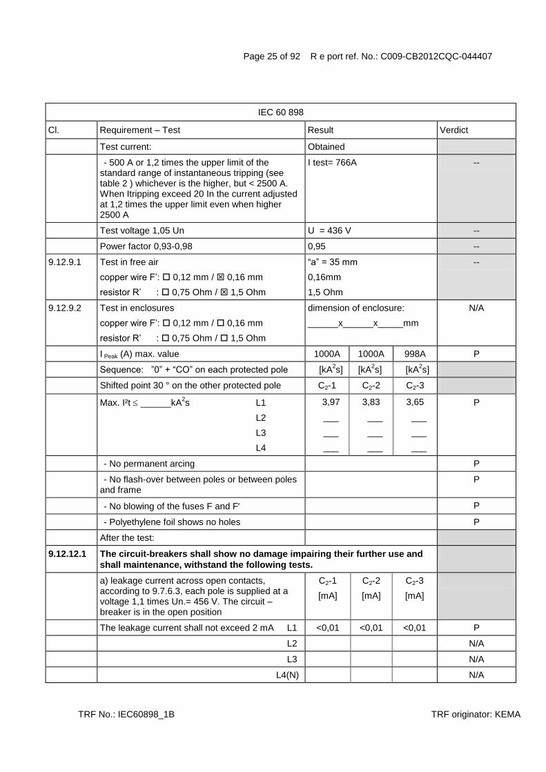
Test current: Obtained
- 500 A or 1,2 times the upper limit of the standard range of instantaneous tripping (see table 2 ) whichever is the higher, but < 2500 A. When Itripping exceed 20 In the current adjusted at 1,2 times the upper limit even when higher 2500 A
I test= 766A --
Test voltage 1,05 Un U = 436 V --
Power factor 0,93-0,98 0,95 --
9.12.9.1 Test in free air
copper wire F‟: 0,12 mm / 0,16 mm
resistor R‟ : 0,75 Ohm / 1,5 Ohm
“a” = 35 mm
0,16mm
1,5 Ohm
--
9.12.9.2 Test in enclosures
copper wire F‟: 0,12 mm / 0,16 mm
resistor R‟ : 0,75 Ohm / 1,5 Ohm
dimension of enclosure:
______x______x_____mm
N/A
I Peak (A) max. value 1000A 1000A 998A P
Sequence: ”0” + “CO” on each protected pole [kA2s] [kA
2s] [kA
2s]
Shifted point 30 ° on the other protected pole C2-1 C2-2 C2-3
Max. I²t ______kA2s L1
L2
L3
L4
3,97
___
___
___
3,83
___
___
___
3,65
___
___
___
P
- No permanent arcing P
- No flash-over between poles or between poles and frame
P
- No blowing of the fuses F and F P
- Polyethylene foil shows no holes P
After the test:
9.12.12.1 The circuit-breakers shall show no damage impairing their further use and
shall maintenance, withstand the following tests.
a) leakage current across open contacts, according to 9.7.6.3, each pole is supplied at a voltage 1,1 times Un.= 456 V. The circuit –breaker is in the open position
C2-1
[mA]
C2-2
[mA]
C2-3
[mA]
The leakage current shall not exceed 2 mA L1 <0,01 <0,01 <0,01 P
L2 N/A
L3 N/A
L4(N) N/A

Page 26 of 92 R e port ref. No.: C009-CB2012CQC-044407
TRF No.: IEC60898_1B TRF originator: KEMA
IEC 60 898
Cl. Requirement – Test Result Verdict
Electric strength test:
Test voltage 1500 V (see 8.7.2)
a) P
b) N/A
c) P
d) N/A
e) 2000 V N/A
TESTS „D“ 3 samples (DL7 C63 1P)
8.6 Automatic operation
8.6.1 Standard time-current zone
Tripping characteristic of CB ensures adequate protection of the circuit, without premature operation.
9.10 Tests: DO D-1 D-2 D-3
IN (A) 63
Sect. (mm²) 16
Instantaneous tripping current B C D
9.10.1 Test of time-current characteristic
9.10.1.1 Test current 1,13 IN (A) starting from cold for: 71,2 A --
- 1 h (IN 63 A) >1 >1 >1 P
- 2 h (IN 63 A) N/A
No tripping P
Then steadily increased within 5 s to 1,45 IN (A) 91,4A --
- Tripping within [min] [min] [min]
- 1h ( 63 A) 50min26s 43min13s 9min49s P
- 2h (> 63 A) N/A
9.10.1.2 Test current 2,55 IN (A) starting from cold for: 160 A --
opening time not less than 1 s or more than [s] [s] [s]
- 60 s N/A
- 120 s 37 36 35 P
9.10.2 Teast of instantaneous tripping and of correct opening of the contacts
9.10.2.1 General test conditions
For the lower values of the test current the test is made once, at any convenient voltage.

Page 27 of 92 R e port ref. No.: C009-CB2012CQC-044407
TRF No.: IEC60898_1B TRF originator: KEMA
IEC 60 898
Cl. Requirement – Test Result Verdict
For the upper values of the test current the test is made at rated voltage Un( phase to neutral) with a power factor between 0,95 and 1.
242V
0,98
--
The sequence of operation is : O-CO-CO-CO
Interval time: > 3 min
The tripping time of the O operation is measured
After each operation the indicating means shall show the open position of the contacts
P
9.10.2.2 For circuit-breakers of the B – Type
Test current 3IN (A), starting from cold
Opening time: [s] [s] [s]
- 0,1s t 45s ( 32A) N/A
- 0,1s t 90s ( 32A) N/A
Test current 5 IN (A), starting from cold N/A
Tripping less than 0,1 s N/A
9.10.2.3 For circuit-breakers of the C – Type
Test current 5IN (A), starting from cold 315A --
Opening time: [s] [s] [s]
- 0,1s t 15s ( 32A) N/A
- 0,1s t 30s ( 32A) 8 9 8 P
Test current 10 IN (A), starting from cold 635A --
Tripping less than 0,1 s 6,32ms 11,5ms 10,0ms P
9.10.2.4 For circuit-breakers of the D – Type
Test current 10IN (A), starting from cold
Opening time: [s] [s] [s]
- 0,1s t 4s ( 32A) N/A
- 0,1s t 8s ( 32A) N/A
Test current 20 IN (A) or to the maximum instantaneous tripping current(see cl. 6, item j), starting from cold
N/A
Tripping less than 0,1 s N/A
9.10.3 Test of effect of single pole loading on the tripping characteristic of multipole circuit-breakers:
Test current 1,1 It (A), (two pole) starting from cold
Tripping within [min] [min] [min]
- 1h N/A

Page 28 of 92 R e port ref. No.: C009-CB2012CQC-044407
TRF No.: IEC60898_1B TRF originator: KEMA
IEC 60 898
Cl. Requirement – Test Result Verdict
- 2h N/A
Test current 1,2 It (A), (three pole or four pole) starting from cold
Tripping within [min] [min] [min]
- 1h N/A
- 2h N/A
9.10.4 Test of effect of ambient temperature on the tripping characteristics
a) Ambient temperature of (-5 2)°C below the ambient air reference temperature
T = -5°C --
Test current 1,13 IN (A) 71,2A --
- Passed for 1h >1h >1h >1h P
- Passed for 2h N/A
Current is then steadily increased to 1,9 IN (A) within 5s
120A --
Tripping within [min] [min] [min]
- 1h 4min04s 8min51s 3min09s P
- 2h N/A
b) Ambient temperature of (40 2)°C T = 40°C --
Test current IN (A) 63,0A --
No tripping within
- 1h >1h >1h >1h P
- 2h N/A
Tests: D1 (DL7 C63 1P) D-1 D-2 D-3
8.9 Resistance to mechanical shock and impact
CB shall have adequate mechanical behaviour so as to withstand the stresses imposed during installation and use
P
9.13.1 Mechanical shock
- 50 falls on two sides of vertical board C P
- Vertical board turned 90° P
- 50 falls on two sides of vertical board C P
During the test the circuit-breakers shall not open P
9.13.2 Mechanical impact
9.13.2.1 All types:
- Impact test: 10 blows-height 10 cm, no damage P

Page 29 of 92 R e port ref. No.: C009-CB2012CQC-044407
TRF No.: IEC60898_1B TRF originator: KEMA
IEC 60 898
Cl. Requirement – Test Result Verdict
9.13.2.2 Screw-in types:
- Torque 2,5 Nm for 1 min, no damage P
9.13.2.3 CB intended to be mounted on a rail
- downward vertical 50 N for 1 min P
- upward vertical 50 N for 1 min, no damage P
9.13.2.4 Plug-in types
The circuit-breaker are mounted in there normal position, complete with plug-in base but without cables and any cover plate
N/A
A force of 20 N applied for 1min to the circuit-breaker (see fig 17).
N/A
During this test the circuit-breaker part shall not become loose from the base and shall not show damage impairing further use.
N/A
9.12.11.3 Test at 1500 A:
Prospective current of 1500 A – power factor 0,93 to 0,98
Prospective current obtained (A) 1,54/1,56kA --
Power factor 0,96/0,97 --
Test voltage 1,05 Un 252/436 V --
Test circuit: figure 3+5 --
T (min) 3 min --
9.12.9.1 Test in free air
copper wire F‟: 0,12 mm / 0,16 mm
resistor R‟ : 0,75 Ohm / 1,5 Ohm
“a” = 35 mm
0,16mm
1,5 Ohm
--
9.12.9.2 Test in enclosures
copper wire F‟: 0,12 mm / 0,16 mm
resistor R‟ : 0,75 Ohm / 1,5 Ohm
dimension of enclosure:
______x______x_____mm
N/A
Sequence 6 x O, 2 x CO, 1 x O
I Peak (A) max. value 1,93kA 1,90kA 1,91kA P
I²t ______ kA2s [kA
2s] [kA
2s] [kA
2s]
Max. I²t ______kA2s L1
L2
L3
N
8,98
___
___
___
8,35
___
___
___
8,85
___
___
___
P
- No permanent arcing P
- No flash-over between poles or between poles and frame
P

Page 30 of 92 R e port ref. No.: C009-CB2012CQC-044407
TRF No.: IEC60898_1B TRF originator: KEMA
IEC 60 898
Cl. Requirement – Test Result Verdict
- No blowing of the fuses F and F P
- Polyethylene foil shows no holes P
After the test:
9.12.12.1 The circuit-breakers shall show no damage impairing their further use and shall maintenance, withstand the following tests.
P
a) leakage current across open contacts, according to 9.7.6.3, each pole is supplied at a voltage 1,1 times Un.=456 V. The circuit –breaker is in the open position
D-1
[mA]
D-2
[mA]
D-3
[mA]
The leakage current shall not exceed 2 mA L1 <0,01 <0,01 <0,01 P
L2 N/A
L3 N/A
L4(N) N/A
Electric strength test:
Test voltage 1500 V (see 8.7.2)
a) P
b) N/A
c) P
d) N/A
e) 2000 V N/A
Test current 0.85x non tripping current (1,13 IN ) 60,5A --
- Passed for 1h > 1h > 1h > 1h P
- Passed for 2h N/A
Current is then steadily increased to 1,1 x tripping current (1,45 IN ) within 5s
100A --
D-1
[min]
D-2
[min]
D-3
[min]
Tripping within 1 hour / 2 hour 14min11s 5min09s 8min16s P
9.10 Tests: DO (DL7 C6 1P) DO 1
IN (A) 6
Sect. (mm²) 1
Instantaneous tripping current B C D
9.10.1 Test of time-current characteristic
9.10.1.1 Test current 1,13 IN (A) starting from cold for: 6,78 A --
- 1 h (IN 63 A) >1 P

Page 31 of 92 R e port ref. No.: C009-CB2012CQC-044407
TRF No.: IEC60898_1B TRF originator: KEMA
IEC 60 898
Cl. Requirement – Test Result Verdict
- 2 h (IN 63 A) N/A
No tripping P
Then steadily increased within 5 s to 1,45 IN (A) 8,70 A --
- Tripping within [min]
- 1h ( 63 A) 3min55s P
- 2h (> 63 A) N/A
9.10.1.2 Test current 2,55 IN (A) starting from cold for: 15,3 A --
opening time not less than 1 s or more than [s]
- 60 s 12 P
- 120 s N/A
9.10.2 Teast of instantaneous tripping and of correct opening of the contacts
9.10.2.1 General test conditions
For the lower values of the test current the test is made once, at any convenient voltage.
For the upper values of the test current the test is made at rated voltage Un( phase to neutral) with a power factor between 0,95 and 1.
242V
0,99
--
The sequence of operation is : O-CO-CO-CO
Interval time: > 3 min
The tripping time of the O operation is measured
After each operation the indicating means shall show the open position of the contacts
P
9.10.2.2 For circuit-breakers of the B – Type
Test current 3IN (A), starting from cold
Opening time: [s] [s] [s]
- 0,1s t 45s ( 32A) N/A
- 0,1s t 90s ( 32A) N/A
Test current 5 IN (A), starting from cold N/A
Tripping less than 0,1 s N/A
9.10.2.3 For circuit-breakers of the C – Type
Test current 5IN (A), starting from cold 30,0A --
Opening time: [s]
- 0,1s t 15s ( 32A) 6 P
- 0,1s t 30s ( 32A) N/A
Test current 10 IN (A), starting from cold 61,2A --
Tripping less than 0,1 s 17,3ms P

Page 32 of 92 R e port ref. No.: C009-CB2012CQC-044407
TRF No.: IEC60898_1B TRF originator: KEMA
IEC 60 898
Cl. Requirement – Test Result Verdict
9.10.2.4 For circuit-breakers of the D – Type
Test current 10IN (A), starting from cold
Opening time: [s] [s] [s]
- 0,1s t 4s ( 32A) N/A
- 0,1s t 8s ( 32A) N/A
Test current 20 IN (A) or to the maximum instantaneous tripping current(see cl. 6, item j), starting from cold
N/A
Tripping less than 0,1 s N/A
9.10.3 Test of effect of single pole loading on the tripping characteristic of multipole circuit-breakers:
Test current 1,1 It (A), (two pole) starting from cold
Tripping within [min] [min] [min]
- 1h N/A
- 2h N/A
Test current 1,2 It (A), (three pole or four pole) starting from cold
Tripping within [min] [min] [min]
- 1h N/A
- 2h N/A
9.10.4 Test of effect of ambient temperature on the tripping characteristics
a) Ambient temperature of (-5 2)°C below the ambient air reference temperature
T = -5°C --
Test current 1,13 IN (A) 6,78 A --
- Passed for 1h >1h P
- Passed for 2h N/A
Current is then steadily increased to 1,9 IN (A) within 5s
11,4 A --
Tripping within [min]
- 1h 3min12s P
- 2h N/A
b) Ambient temperature of (40 2)°C T = 40°C --
Test current IN (A) 6,00A --
No tripping within
- 1h >1h P
- 2h N/A

Page 33 of 92 R e port ref. No.: C009-CB2012CQC-044407
TRF No.: IEC60898_1B TRF originator: KEMA
IEC 60 898
Cl. Requirement – Test Result Verdict
9.10 Tests: DO (DL7 C10 1P) DO 2
IN (A) 10
Sect. (mm²) 1,5
Instantaneous tripping current B C D
9.10.1 Test of time-current characteristic
9.10.1.1 Test current 1,13 IN (A) starting from cold for: 11,3 A --
- 1 h (IN 63 A) >1 P
- 2 h (IN 63 A) N/A
No tripping P
Then steadily increased within 5 s to 1,45 IN (A) 14,5 A --
- Tripping within [min]
- 1h ( 63 A) 7min42s P
- 2h (> 63 A) N/A
9.10.1.2 Test current 2,55 IN (A) starting from cold for: 25,5 A --
opening time not less than 1 s or more than [s]
- 60 s 14 P
- 120 s N/A
9.10.2 Teast of instantaneous tripping and of correct opening of the contacts
9.10.2.1 General test conditions
For the lower values of the test current the test is made once, at any convenient voltage.
For the upper values of the test current the test is made at rated voltage Un( phase to neutral) with a power factor between 0,95 and 1.
242V
0,99
--
The sequence of operation is : O-CO-CO-CO
Interval time: > 3 min
The tripping time of the O operation is measured
After each operation the indicating means shall show the open position of the contacts
P
9.10.2.2 For circuit-breakers of the B – Type
Test current 3IN (A), starting from cold
Opening time: [s] [s] [s]
- 0,1s t 45s ( 32A) N/A
- 0,1s t 90s ( 32A) N/A
Test current 5 IN (A), starting from cold N/A
Tripping less than 0,1 s N/A

Page 34 of 92 R e port ref. No.: C009-CB2012CQC-044407
TRF No.: IEC60898_1B TRF originator: KEMA
IEC 60 898
Cl. Requirement – Test Result Verdict
9.10.2.3 For circuit-breakers of the C – Type
Test current 5IN (A), starting from cold 50,0A --
Opening time: [s]
- 0,1s t 15s ( 32A) 4 P
- 0,1s t 30s ( 32A) N/A
Test current 10 IN (A), starting from cold 102A --
Tripping less than 0,1 s 14,5 ms P
9.10.2.4 For circuit-breakers of the D – Type
Test current 10IN (A), starting from cold
Opening time: [s] [s] [s]
- 0,1s t 4s ( 32A) N/A
- 0,1s t 8s ( 32A) N/A
Test current 20 IN (A) or to the maximum instantaneous tripping current(see cl. 6, item j), starting from cold
N/A
Tripping less than 0,1 s N/A
9.10.3 Test of effect of single pole loading on the tripping characteristic of multipole circuit-breakers:
Test current 1,1 It (A), (two pole) starting from cold
Tripping within [min] [min] [min]
- 1h N/A
- 2h N/A
Test current 1,2 It (A), (three pole or four pole) starting from cold
Tripping within [min] [min] [min]
- 1h N/A
- 2h N/A
9.10.4 Test of effect of ambient temperature on the tripping characteristics
a) Ambient temperature of (-5 2)°C below the ambient air reference temperature
T = -5°C --
Test current 1,13 IN (A) 11,3 A --
- Passed for 1h >1h P
- Passed for 2h N/A
Current is then steadily increased to 1,9 IN (A) within 5s
19,0 A --

Page 35 of 92 R e port ref. No.: C009-CB2012CQC-044407
TRF No.: IEC60898_1B TRF originator: KEMA
IEC 60 898
Cl. Requirement – Test Result Verdict
Tripping within [min]
- 1h 4min17s P
- 2h N/A
b) Ambient temperature of (40 2)°C T = 40°C --
Test current IN (A) 10,0A --
No tripping within
- 1h >1h P
- 2h N/A
9.10 Tests: DO (DL7 C16 1P) DO 3
IN (A) 16
Sect. (mm²) 2,5
Instantaneous tripping current B C D
9.10.1 Test of time-current characteristic
9.10.1.1 Test current 1,13 IN (A) starting from cold for: 18,1 A --
- 1 h (IN 63 A) >1 P
- 2 h (IN 63 A) N/A
No tripping
Then steadily increased within 5 s to 1,45 IN (A) 23,2 A --
- Tripping within [min]
- 1h ( 63 A) 29s P
- 2h (> 63 A) N/A
9.10.1.2 Test current 2,55 IN (A) starting from cold for: 40,8 A --
opening time not less than 1 s or more than [s]
- 60 s 13 P
- 120 s N/A
9.10.2 Teast of instantaneous tripping and of correct opening of the contacts
9.10.2.1 General test conditions
For the lower values of the test current the test is made once, at any convenient voltage.
For the upper values of the test current the test is made at rated voltage Un( phase to neutral) with a power factor between 0,95 and 1.
242V
0,99
--
The sequence of operation is : O-CO-CO-CO
Interval time: > 3 min
The tripping time of the O operation is measured

Page 36 of 92 R e port ref. No.: C009-CB2012CQC-044407
TRF No.: IEC60898_1B TRF originator: KEMA
IEC 60 898
Cl. Requirement – Test Result Verdict
After each operation the indicating means shall show the open position of the contacts
P
9.10.2.2 For circuit-breakers of the B – Type
Test current 3IN (A), starting from cold
Opening time: [s] [s] [s]
- 0,1s t 45s ( 32A) N/A
- 0,1s t 90s ( 32A) N/A
Test current 5 IN (A), starting from cold N/A
Tripping less than 0,1 s N/A
9.10.2.3 For circuit-breakers of the C – Type
Test current 5IN (A), starting from cold 80,0A --
Opening time: [s]
- 0,1s t 15s ( 32A) 4 P
- 0,1s t 30s ( 32A) N/A
Test current 10 IN (A), starting from cold 165A --
Tripping less than 0,1 s 8,11ms P
9.10.2.4 For circuit-breakers of the D – Type
Test current 10IN (A), starting from cold
Opening time: [s] [s] [s]
- 0,1s t 4s ( 32A) N/A
- 0,1s t 8s ( 32A) N/A
Test current 20 IN (A) or to the maximum instantaneous tripping current(see cl. 6, item j), starting from cold
N/A
Tripping less than 0,1 s N/A
9.10.3 Test of effect of single pole loading on the tripping characteristic of multipole circuit-breakers:
Test current 1,1 It (A), (two pole) starting from cold
Tripping within [min] [min] [min]
- 1h N/A
- 2h N/A
Test current 1,2 It (A), (three pole or four pole) starting from cold
Tripping within [min] [min] [min]
- 1h N/A
- 2h N/A

Page 37 of 92 R e port ref. No.: C009-CB2012CQC-044407
TRF No.: IEC60898_1B TRF originator: KEMA
IEC 60 898
Cl. Requirement – Test Result Verdict
9.10.4 Test of effect of ambient temperature on the tripping characteristics
a) Ambient temperature of (-5 2)°C below the ambient air reference temperature
T = -5°C --
Test current 1,13 IN (A) 18,1 A --
- Passed for 1h >1h P
- Passed for 2h N/A
Current is then steadily increased to 1,9 IN (A) within 5s
30,4 A --
Tripping within [min]
- 1h 19s P
- 2h N/A
b) Ambient temperature of (40 2)°C T = 40°C --
Test current IN (A) 16,0A --
No tripping within
- 1h >1h P
- 2h N/A
9.10 Tests: DO (DL7 C20 1P) DO 4
IN (A) 20
Sect. (mm²) 2,5
Instantaneous tripping current B C D
9.10.1 Test of time-current characteristic
9.10.1.1 Test current 1,13 IN (A) starting from cold for: 22,6 A --
- 1 h (IN 63 A) >1 P
- 2 h (IN 63 A) N/A
No tripping
Then steadily increased within 5 s to 1,45 IN (A) 29,0 A --
- Tripping within [min]
- 1h ( 63 A) 43s P
- 2h (> 63 A) N/A
9.10.1.2 Test current 2,55 IN (A) starting from cold for: 51,0 A --
opening time not less than 1 s or more than [s]
- 60 s 11 P
- 120 s N/A

Page 38 of 92 R e port ref. No.: C009-CB2012CQC-044407
TRF No.: IEC60898_1B TRF originator: KEMA
IEC 60 898
Cl. Requirement – Test Result Verdict
9.10.2 Teast of instantaneous tripping and of correct opening of the contacts
9.10.2.1 General test conditions
For the lower values of the test current the test is made once, at any convenient voltage.
For the upper values of the test current the test is made at rated voltage Un( phase to neutral) with a power factor between 0,95 and 1.
242V
0,98
--
The sequence of operation is : O-CO-CO-CO
Interval time: > 3 min
The tripping time of the O operation is measured
After each operation the indicating means shall show the open position of the contacts
P
9.10.2.2 For circuit-breakers of the B – Type
Test current 3IN (A), starting from cold
Opening time: [s] [s] [s]
- 0,1s t 45s ( 32A) N/A
- 0,1s t 90s ( 32A) N/A
Test current 5 IN (A), starting from cold N/A
Tripping less than 0,1 s N/A
9.10.2.3 For circuit-breakers of the C – Type
Test current 5IN (A), starting from cold 100A --
Opening time: [s]
- 0,1s t 15s ( 32A) 5 P
- 0,1s t 30s ( 32A) N/A
Test current 10 IN (A), starting from cold 204A --
Tripping less than 0,1 s 8,55ms P
9.10.2.4 For circuit-breakers of the D – Type
Test current 10IN (A), starting from cold
Opening time: [s] [s] [s]
- 0,1s t 4s ( 32A) N/A
- 0,1s t 8s ( 32A) N/A
Test current 20 IN (A) or to the maximum instantaneous tripping current(see cl. 6, item j), starting from cold
N/A
Tripping less than 0,1 s N/A
9.10.3 Test of effect of single pole loading on the tripping characteristic of multipole circuit-breakers:

Page 39 of 92 R e port ref. No.: C009-CB2012CQC-044407
TRF No.: IEC60898_1B TRF originator: KEMA
IEC 60 898
Cl. Requirement – Test Result Verdict
Test current 1,1 It (A), (two pole) starting from cold
Tripping within [min] [min] [min]
- 1h N/A
- 2h N/A
Test current 1,2 It (A), (three pole or four pole) starting from cold
Tripping within [min] [min] [min]
- 1h N/A
- 2h N/A
9.10.4 Test of effect of ambient temperature on the tripping characteristics
a) Ambient temperature of (-5 2)°C below the ambient air reference temperature
T = -5°C --
Test current 1,13 IN (A) 22,6 A --
- Passed for 1h >1h P
- Passed for 2h N/A
Current is then steadily increased to 1,9 IN (A) within 5s
38,0 A --
Tripping within [min]
- 1h 18s P
- 2h N/A
b) Ambient temperature of (40 2)°C T = 40°C --
Test current IN (A) 20,0A --
No tripping within
- 1h >1h P
- 2h N/A
9.10 Tests: DO (DL7 C25 1P) DO 5
IN (A) 25
Sect. (mm²) 4
Instantaneous tripping current B C D
9.10.1 Test of time-current characteristic
9.10.1.1 Test current 1,13 IN (A) starting from cold for: 28,3 A --
- 1 h (IN 63 A) >1 P
- 2 h (IN 63 A) N/A
No tripping P

Page 40 of 92 R e port ref. No.: C009-CB2012CQC-044407
TRF No.: IEC60898_1B TRF originator: KEMA
IEC 60 898
Cl. Requirement – Test Result Verdict
Then steadily increased within 5 s to 1,45 IN (A) 36,3A --
- Tripping within [min]
- 1h ( 63 A) 38s P
- 2h (> 63 A) N/A
9.10.1.2 Test current 2,55 IN (A) starting from cold for: 63,8 A --
opening time not less than 1 s or more than [s]
- 60 s 13 P
- 120 s N/A
9.10.2 Teast of instantaneous tripping and of correct opening of the contacts
9.10.2.1 General test conditions
For the lower values of the test current the test is made once, at any convenient voltage.
For the upper values of the test current the test is made at rated voltage Un( phase to neutral) with a power factor between 0,95 and 1.
242V
0,98
--
The sequence of operation is : O-CO-CO-CO
Interval time: > 3 min
The tripping time of the O operation is measured
After each operation the indicating means shall show the open position of the contacts
P
9.10.2.2 For circuit-breakers of the B – Type
Test current 3IN (A), starting from cold
Opening time: [s] [s] [s]
- 0,1s t 45s ( 32A) N/A
- 0,1s t 90s ( 32A) N/A
Test current 5 IN (A), starting from cold N/A
Tripping less than 0,1 s N/A
9.10.2.3 For circuit-breakers of the C – Type
Test current 5IN (A), starting from cold 125A --
Opening time: [s]
- 0,1s t 15s ( 32A) 7 P
- 0,1s t 30s ( 32A) N/A
Test current 10 IN (A), starting from cold 256A --
Tripping less than 0,1 s 14,1ms P
9.10.2.4 For circuit-breakers of the D – Type
Test current 10IN (A), starting from cold

Page 41 of 92 R e port ref. No.: C009-CB2012CQC-044407
TRF No.: IEC60898_1B TRF originator: KEMA
IEC 60 898
Cl. Requirement – Test Result Verdict
Opening time: [s] [s] [s]
- 0,1s t 4s ( 32A) N/A
- 0,1s t 8s ( 32A) N/A
Test current 20 IN (A) or to the maximum instantaneous tripping current(see cl. 6, item j), starting from cold
N/A
Tripping less than 0,1 s N/A
9.10.3 Test of effect of single pole loading on the tripping characteristic of multipole circuit-breakers:
Test current 1,1 It (A), (two pole) starting from cold
Tripping within [min] [min] [min]
- 1h N/A
- 2h N/A
Test current 1,2 It (A), (three pole or four pole) starting from cold
Tripping within [min] [min] [min]
- 1h N/A
- 2h N/A
9.10.4 Test of effect of ambient temperature on the tripping characteristics
a) Ambient temperature of (-5 2)°C below the ambient air reference temperature
T = -5°C --
Test current 1,13 IN (A) 28,3A --
- Passed for 1h >1h P
- Passed for 2h N/A
Current is then steadily increased to 1,9 IN (A) within 5s
47,5A --
Tripping within [min]
- 1h 13s P
- 2h N/A
b) Ambient temperature of (40 2)°C T = 40°C --
Test current IN (A) 25,0A --
No tripping within
- 1h >1h P
- 2h N/A

Page 42 of 92 R e port ref. No.: C009-CB2012CQC-044407
TRF No.: IEC60898_1B TRF originator: KEMA
IEC 60 898
Cl. Requirement – Test Result Verdict
9.10 Tests: DO (DL7 C32 1P) DO 6
IN (A) 32
Sect. (mm²) 6
Instantaneous tripping current B C D
9.10.1 Test of time-current characteristic
9.10.1.1 Test current 1,13 IN (A) starting from cold for: 36,2 A --
- 1 h (IN 63 A) >1 P
- 2 h (IN 63 A) N/A
No tripping
Then steadily increased within 5 s to 1,45 IN (A) 46,4 A --
- Tripping within [min]
- 1h ( 63 A) 1min17s P
- 2h (> 63 A) N/A
9.10.1.2 Test current 2,55 IN (A) starting from cold for: 81,6 A --
opening time not less than 1 s or more than [s]
- 60 s 9 P
- 120 s N/A
9.10.2 Teast of instantaneous tripping and of correct opening of the contacts
9.10.2.1 General test conditions
For the lower values of the test current the test is made once, at any convenient voltage.
For the upper values of the test current the test is made at rated voltage Un( phase to neutral) with a power factor between 0,95 and 1.
242V
0,98
--
The sequence of operation is : O-CO-CO-CO
Interval time: > 3 min
The tripping time of the O operation is measured
After each operation the indicating means shall show the open position of the contacts
P
9.10.2.2 For circuit-breakers of the B – Type
Test current 3IN (A), starting from cold
Opening time: [s] [s] [s]
- 0,1s t 45s ( 32A) N/A
- 0,1s t 90s ( 32A) N/A
Test current 5 IN (A), starting from cold N/A
Tripping less than 0,1 s N/A

Page 43 of 92 R e port ref. No.: C009-CB2012CQC-044407
TRF No.: IEC60898_1B TRF originator: KEMA
IEC 60 898
Cl. Requirement – Test Result Verdict
9.10.2.3 For circuit-breakers of the C – Type
Test current 5IN (A), starting from cold 160A --
Opening time: [s]
- 0,1s t 15s ( 32A) 6 P
- 0,1s t 30s ( 32A) N/A
Test current 10 IN (A), starting from cold 326A --
Tripping less than 0,1 s 7,14ms P
9.10.2.4 For circuit-breakers of the D – Type
Test current 10IN (A), starting from cold
Opening time: [s] [s] [s]
- 0,1s t 4s ( 32A) N/A
- 0,1s t 8s ( 32A) N/A
Test current 20 IN (A) or to the maximum instantaneous tripping current(see cl. 6, item j), starting from cold
N/A
Tripping less than 0,1 s N/A
9.10.3 Test of effect of single pole loading on the tripping characteristic of multipole circuit-breakers:
Test current 1,1 It (A), (two pole) starting from cold
Tripping within [min] [min] [min]
- 1h N/A
- 2h N/A
Test current 1,2 It (A), (three pole or four pole) starting from cold
Tripping within [min] [min] [min]
- 1h N/A
- 2h N/A
9.10.4 Test of effect of ambient temperature on the tripping characteristics
a) Ambient temperature of (-5 2)°C below the ambient air reference temperature
T = -5°C --
Test current 1,13 IN (A) 36,2 A --
- Passed for 1h >1h P
- Passed for 2h N/A
Current is then steadily increased to 1,9 IN (A) within 5s
60,8 A --

Page 44 of 92 R e port ref. No.: C009-CB2012CQC-044407
TRF No.: IEC60898_1B TRF originator: KEMA
IEC 60 898
Cl. Requirement – Test Result Verdict
Tripping within [min]
- 1h 1min02s P
- 2h N/A
b) Ambient temperature of (40 2)°C T = 40°C --
Test current IN (A) 32,0A --
No tripping within
- 1h >1h P
- 2h N/A
9.10 Tests: DO (DL7 C40 1P) DO 7
IN (A) 40
Sect. (mm²) 10
Instantaneous tripping current B C D
9.10.1 Test of time-current characteristic
9.10.1.1 Test current 1,13 IN (A) starting from cold for: 45,2 A --
- 1 h (IN 63 A) >1 P
- 2 h (IN 63 A) N/A
No tripping
Then steadily increased within 5 s to 1,45 IN (A) 58,0 A --
- Tripping within [min]
- 1h ( 63 A) 32s P
- 2h (> 63 A) N/A
9.10.1.2 Test current 2,55 IN (A) starting from cold for: 102 A --
opening time not less than 1 s or more than [s]
- 60 s N/A
- 120 s 11 P
9.10.2 Teast of instantaneous tripping and of correct opening of the contacts
9.10.2.1 General test conditions
For the lower values of the test current the test is made once, at any convenient voltage.
For the upper values of the test current the test is made at rated voltage Un( phase to neutral) with a power factor between 0,95 and 1.
242V
0,98
--
The sequence of operation is : O-CO-CO-CO
Interval time: > 3 min
The tripping time of the O operation is measured

Page 45 of 92 R e port ref. No.: C009-CB2012CQC-044407
TRF No.: IEC60898_1B TRF originator: KEMA
IEC 60 898
Cl. Requirement – Test Result Verdict
After each operation the indicating means shall show the open position of the contacts
P
9.10.2.2 For circuit-breakers of the B – Type
Test current 3IN (A), starting from cold
Opening time: [s] [s] [s]
- 0,1s t 45s ( 32A) N/A
- 0,1s t 90s ( 32A) N/A
Test current 5 IN (A), starting from cold N/A
Tripping less than 0,1 s N/A
9.10.2.3 For circuit-breakers of the C – Type
Test current 5IN (A), starting from cold 200A --
Opening time: [s]
- 0,1s t 15s ( 32A) N/A
- 0,1s t 30s ( 32A) 4 P
Test current 10 IN (A), starting from cold 405A --
Tripping less than 0,1 s 8,51ms P
9.10.2.4 For circuit-breakers of the D – Type
Test current 10IN (A), starting from cold
Opening time: [s] [s] [s]
- 0,1s t 4s ( 32A) N/A
- 0,1s t 8s ( 32A) N/A
Test current 20 IN (A) or to the maximum instantaneous tripping current(see cl. 6, item j), starting from cold
N/A
Tripping less than 0,1 s N/A
9.10.3 Test of effect of single pole loading on the tripping characteristic of multipole circuit-breakers:
Test current 1,1 It (A), (two pole) starting from cold
Tripping within [min] [min] [min]
- 1h N/A
- 2h N/A
Test current 1,2 It (A), (three pole or four pole) starting from cold
Tripping within [min] [min] [min]
- 1h N/A
- 2h N/A

Page 46 of 92 R e port ref. No.: C009-CB2012CQC-044407
TRF No.: IEC60898_1B TRF originator: KEMA
IEC 60 898
Cl. Requirement – Test Result Verdict
9.10.4 Test of effect of ambient temperature on the tripping characteristics
a) Ambient temperature of (-5 2)°C below the ambient air reference temperature
T = -5°C --
Test current 1,13 IN (A) 45,2 A --
- Passed for 1h >1h P
- Passed for 2h N/A
Current is then steadily increased to 1,9 IN (A) within 5s
76,0 A --
Tripping within [min]
- 1h 18s P
- 2h N/A
b) Ambient temperature of (40 2)°C T = 40°C --
Test current IN (A) 40,0A --
No tripping within
- 1h >1h P
- 2h N/A
9.10 Tests: DO (DL7 C50 1P) DO 8
IN (A) 50
Sect. (mm²) 10
Instantaneous tripping current B C D
9.10.1 Test of time-current characteristic
9.10.1.1 Test current 1,13 IN (A) starting from cold for: 56,5 A --
- 1 h (IN 63 A) >1 P
- 2 h (IN 63 A) N/A
No tripping
Then steadily increased within 5 s to 1,45 IN (A) 72,5 A --
- Tripping within [min]
- 1h ( 63 A) 33s P
- 2h (> 63 A) N/A
9.10.1.2 Test current 2,55 IN (A) starting from cold for: 128 A --
opening time not less than 1 s or more than [s]
- 60 s N/A
- 120 s 12 P

Page 47 of 92 R e port ref. No.: C009-CB2012CQC-044407
TRF No.: IEC60898_1B TRF originator: KEMA
IEC 60 898
Cl. Requirement – Test Result Verdict
9.10.2 Teast of instantaneous tripping and of correct opening of the contacts
9.10.2.1 General test conditions
For the lower values of the test current the test is made once, at any convenient voltage.
For the upper values of the test current the test is made at rated voltage Un( phase to neutral) with a power factor between 0,95 and 1.
242V
0,98
--
The sequence of operation is : O-CO-CO-CO
Interval time: > 3 min
The tripping time of the O operation is measured
After each operation the indicating means shall show the open position of the contacts
P
9.10.2.2 For circuit-breakers of the B – Type
Test current 3IN (A), starting from cold
Opening time: [s] [s] [s]
- 0,1s t 45s ( 32A) N/A
- 0,1s t 90s ( 32A) N/A
Test current 5 IN (A), starting from cold N/A
Tripping less than 0,1 s N/A
9.10.2.3 For circuit-breakers of the C – Type
Test current 5IN (A), starting from cold 250A --
Opening time: [s]
- 0,1s t 15s ( 32A) N/A
- 0,1s t 30s ( 32A) 4 P
Test current 10 IN (A), starting from cold 512A --
Tripping less than 0,1 s 5,72ms P
9.10.2.4 For circuit-breakers of the D – Type
Test current 10IN (A), starting from cold
Opening time: [s] [s] [s]
- 0,1s t 4s ( 32A) N/A
- 0,1s t 8s ( 32A) N/A
Test current 20 IN (A) or to the maximum instantaneous tripping current(see cl. 6, item j), starting from cold
N/A
Tripping less than 0,1 s N/A
9.10.3 Test of effect of single pole loading on the tripping characteristic of multipole circuit-breakers:

Page 48 of 92 R e port ref. No.: C009-CB2012CQC-044407
TRF No.: IEC60898_1B TRF originator: KEMA
IEC 60 898
Cl. Requirement – Test Result Verdict
Test current 1,1 It (A), (two pole) starting from cold
Tripping within [min] [min] [min]
- 1h N/A
- 2h N/A
Test current 1,2 It (A), (three pole or four pole) starting from cold
Tripping within [min] [min] [min]
- 1h N/A
- 2h N/A
9.10.4 Test of effect of ambient temperature on the tripping characteristics
a) Ambient temperature of (-5 2)°C below the ambient air reference temperature
T = -5°C --
Test current 1,13 IN (A) 56,5 A --
- Passed for 1h >1h P
- Passed for 2h N/A
Current is then steadily increased to 1,9 IN (A) within 5s
95,0 A --
Tripping within [min]
- 1h 19s P
- 2h N/A
b) Ambient temperature of (40 2)°C T = 40°C --
Test current IN (A) 50,0A --
No tripping within
- 1h >1h P
- 2h N/A

Page 49 of 92 R e port ref. No.: C009-CB2012CQC-044407
TRF No.: IEC60898_1B TRF originator: KEMA
TESTS „E“ 3 + 3 samples (DL7 C63 1P)
8.12.11.4.2 Test: E1(Test at service short-circuit capacity) E1-1 E1-2 E1-3
Service short-circuit capacity .............................. : 7500 A --
Test circuit: figure................................................ : 3 --
Prospective current ............................................. : 7500 A --
Prospective current obtained .............................. : 7520 A --
Power factor ........................................................ : 0,45~0,50 --
Power factor obtained ......................................... : 0,50 --
Sequence ............................................................ : O - T – O - T – CO --
T (min)................................................................. : 3 min --
9.12.9.1 Test in free air
copper wire F‟: 0,12 mm / 0,16 mm
resistor R‟ : 0,75 Ohm / 1,5 Ohm
“a” = 50 mm
0,16mm
1,5 Ohm
--
9.12.9.2 Test in enclosures
copper wire F‟: 0,12 mm / 0,16 mm
resistor R‟ : 0,75 Ohm / 1,5 Ohm
dimension of enclosure:
______x______x_____mm
N/A
IPeak (A) max. value ............................................. : 4,96kA 4,85kA 4,69kA P
I²t ______ kA2s [kA
2s] [kA
2s] [kA
2s]
Max. I²t ______kA2s L1
L2
L3
N
79,7
___
___
___
67,3
___
___
___
98,6
___
___
___
P
- No permanent arcing P
- No flash-over between poles or between poles and frame
P
- No blowing of the fuses F and F P
- Polyethylene foil shows no holes P
After the test:
9.12.12.1 The circuit-breakers shall show no damage
impairing their further use and shall
maintenance, withstand the following tests.
a) leakage current across open contacts, according to 9.7.6.3, each pole is supplied at a voltage 1,1 times Un.= 264 V. The circuit –breaker is in the open position
E1-1
[mA]
E1-2
[mA]
E1-3
[mA]
The leakage current shall not exceed 2 mA L1 0,005 0,005 0,005 P
L2 N/A
L3 N/A

Page 50 of 92 R e port ref. No.: C009-CB2012CQC-044407
TRF No.: IEC60898_1B TRF originator: KEMA
L4(N) N/A
Electric strength test:
Test voltage 1500 V (see 8.7.2)
a) P
b) N/A
c) P
d) N/A
e) 2000 V N/A
Test current 0.85x non tripping current (1,13 IN ) 60,5 A --
- Passed for 1h > 1h > 1h > 1h P
- Passed for 2h N/A
Current is then steadily increased to 1,1 x tripping current (1,45 IN ) within 5s
100 A --
E1-1
[min]
E1-2
[min]
E1-3
[min]
Tripping within 1 hour / 2 hour 1min04s 6min28s 2min42s P

Page 51 of 92 R e port ref. No.: C009-CB2012CQC-044407
TRF No.: IEC60898_1B TRF originator: KEMA
TESTS „E“ 3 + 3 samples (DL7 C6 1P)
8.12.11.4.2 Test: E1(Test at service short-circuit capacity) E1-4 E1-5 E1-6
Service short-circuit capacity .............................. : 7500 A --
Test circuit: figure................................................ : 3 --
Prospective current ............................................. : 7500 A --
Prospective current obtained .............................. : 7520 A --
Power factor ........................................................ : 0,45~0,50 --
Power factor obtained ......................................... : 0,50 --
Sequence ............................................................ : O - T – O - T – CO --
T (min)................................................................. : 3 min --
9.12.9.1 Test in free air
copper wire F‟: 0,12 mm / 0,16 mm
resistor R‟ : 0,75 Ohm / 1,5 Ohm
“a” = 50 mm
0,16mm
1,5 Ohm
--
9.12.9.2 Test in enclosures
copper wire F‟: 0,12 mm / 0,16 mm
resistor R‟ : 0,75 Ohm / 1,5 Ohm
dimension of enclosure:
______x______x_____mm
N/A
IPeak (A) max. value ............................................. : 2,35kA 2,97kA 2,91kA P
I²t ______ kA2s [kA
2s] [kA
2s] [kA
2s]
Max. I²t ______kA2s L1
L2
L3
N
8,26
___
___
___
18,1
___
___
___
45,8
___
___
___
P
- No permanent arcing P
- No flash-over between poles or between poles and frame
P
- No blowing of the fuses F and F P
- Polyethylene foil shows no holes P
After the test:
9.12.12.1 The circuit-breakers shall show no damage
impairing their further use and shall
maintenance, withstand the following tests.
a) leakage current across open contacts, according to 9.7.6.3, each pole is supplied at a voltage 1,1 times Un.= 264 V. The circuit –breaker is in the open position
E1-4
[mA]
E1-5
[mA]
E1-6
[mA]
The leakage current shall not exceed 2 mA L1 0,005 0,005 0,005 P
L2 N/A

Page 52 of 92 R e port ref. No.: C009-CB2012CQC-044407
TRF No.: IEC60898_1B TRF originator: KEMA
L3 N/A
L4(N) N/A
Electric strength test:
Test voltage 1500 V (see 8.7.2)
a) P
b) N/A
c) P
d) N/A
e) 2000 V N/A
Test current 0.85x non tripping current (1,13 IN ) 5,76A --
- Passed for 1h > 1h > 1h > 1h P
- Passed for 2h N/A
Current is then steadily increased to 1,1 x tripping current (1,45 IN ) within 5s
9,57 A --
E1-4
[min]
E1-5
[min]
E1-6
[min]
Tripping within 1 hour / 2 hour 49s 2min10s 6min24s P

Page 53 of 92 R e port ref. No.: C009-CB2012CQC-044407
TRF No.: IEC60898_1B TRF originator: KEMA
TESTS „E“ 3 + 3 samples (DL7 C63 2P)
8.12.11.4.2 Test: E1(Test at service short-circuit capacity) E1-7(F1) E1-8(F1) E1-9(F1)
Service short-circuit capacity .............................. : 7500 A --
Test circuit: figure................................................ : 4b --
Prospective current ............................................. : 7500 A --
Prospective current obtained .............................. : 7530 A --
Power factor ........................................................ : 0,45~0,50 --
Power factor obtained ......................................... : 0,50 --
Sequence ............................................................ : O - T – O - T – CO --
T (min)................................................................. : 3 min --
9.12.9.1 Test in free air
copper wire F‟: 0,12 mm / 0,16 mm
resistor R‟ : 0,75 Ohm / 1,5 Ohm
“a” = 50 mm
0,16mm
1,5 Ohm
--
9.12.9.2 Test in enclosures
copper wire F‟: 0,12 mm / 0,16 mm
resistor R‟ : 0,75 Ohm / 1,5 Ohm
dimension of enclosure:
______x______x_____mm
N/A
IPeak (A) max. value ............................................. : 4,02kA 4,00kA 5,62kA P
I²t ______ kA2s [kA
2s] [kA
2s] [kA
2s]
Max. I²t ______kA2s L1
L2
L3
N
62,4
___
___
___
39,3
___
___
___
141
___
___
___
P
- No permanent arcing P
- No flash-over between poles or between poles and frame
P
- No blowing of the fuses F and F P
- Polyethylene foil shows no holes P
After the test:
9.12.12.1 The circuit-breakers shall show no damage
impairing their further use and shall
maintenance, withstand the following tests.
a) leakage current across open contacts, according to 9.7.6.3, each pole is supplied at a voltage 1,1 times Un.= 264 V. The circuit –breaker is in the open position
E1-7(F1)
[mA]
E1-8(F1)
[mA]
E1-9(F1)
[mA]
The leakage current shall not exceed 2 mA L1 0,005 0,005 0,005 P
L2 0,005 0,005 0,005 P
L3 N/A
L4(N) N/A

Page 54 of 92 R e port ref. No.: C009-CB2012CQC-044407
TRF No.: IEC60898_1B TRF originator: KEMA
Electric strength test:
Test voltage 1500 V (see 8.7.2)
a) P
b) N/A
c) P
d) N/A
e) 2000 V N/A
Test current 0.85x non tripping current (1,13 IN ) 60,5 A --
- Passed for 1h > 1h > 1h > 1h P
- Passed for 2h N/A
Current is then steadily increased to 1,1 x tripping current (1,45 IN ) within 5s
100 A --
E1-7(F1)
[min]
E1-8(F1)
[min]
E1-9(F1)
[min]
Tripping within 1 hour / 2 hour 12s 1min06s 37s P

Page 55 of 92 R e port ref. No.: C009-CB2012CQC-044407
TRF No.: IEC60898_1B TRF originator: KEMA
TESTS „E“ 3 + 3 samples (DL7 C6 2P)
8.12.11.4.2 Test: E1(Test at service short-circuit capacity) E1-10 E1-11 E1-12
Service short-circuit capacity .............................. : 7500 A --
Test circuit: figure................................................ : 4b --
Prospective current ............................................. : 7500 A --
Prospective current obtained .............................. : 7530 A --
Power factor ........................................................ : 0,45~0,50 --
Power factor obtained ......................................... : 0,50 --
Sequence ............................................................ : O - T – O - T – CO --
T (min)................................................................. : 3 min --
9.12.9.1 Test in free air
copper wire F‟: 0,12 mm / 0,16 mm
resistor R‟ : 0,75 Ohm / 1,5 Ohm
“a” = 50 mm
0,16mm
1,5 Ohm
--
9.12.9.2 Test in enclosures
copper wire F‟: 0,12 mm / 0,16 mm
resistor R‟ : 0,75 Ohm / 1,5 Ohm
dimension of enclosure:
______x______x_____mm
N/A
IPeak (A) max. value ............................................. : 2,58kA 2,74kA 2,76kA P
I²t ______ kA2s [kA
2s] [kA
2s] [kA
2s]
Max. I²t ______kA2s L1
L2
L3
N
11,0
___
___
___
19,0
___
___
___
13,5
___
___
___
P
- No permanent arcing P
- No flash-over between poles or between poles and frame
P
- No blowing of the fuses F and F P
- Polyethylene foil shows no holes P
After the test:
9.12.12.1 The circuit-breakers shall show no damage
impairing their further use and shall
maintenance, withstand the following tests.
a) leakage current across open contacts, according to 9.7.6.3, each pole is supplied at a voltage 1,1 times Un.= 264 V. The circuit –breaker is in the open position
E1-10
[mA]
E1-11
[mA]
E1-12
[mA]
The leakage current shall not exceed 2 mA L1 0,005 0,005 0,005 P
L2 0,005 0,005 0,005 P
L3 N/A
L4(N) N/A

Page 56 of 92 R e port ref. No.: C009-CB2012CQC-044407
TRF No.: IEC60898_1B TRF originator: KEMA
Electric strength test:
Test voltage 1500 V (see 8.7.2)
a) P
b) N/A
c) P
d) N/A
e) 2000 V N/A
Test current 0.85x non tripping current (1,13 IN ) 5,76A --
- Passed for 1h > 1h > 1h > 1h P
- Passed for 2h N/A
Current is then steadily increased to 1,1 x tripping current (1,45 IN ) within 5s
9,57 A --
E1-10
[min]
E1-11
[min]
E1-12
[min]
Tripping within 1 hour / 2 hour 1min24s 50s 3min10s P
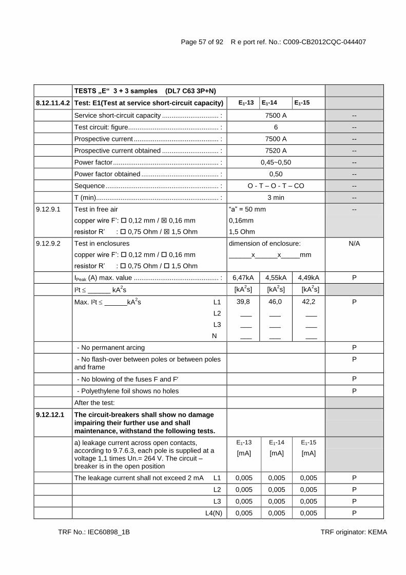
Page 57 of 92 R e port ref. No.: C009-CB2012CQC-044407
TRF No.: IEC60898_1B TRF originator: KEMA
TESTS „E“ 3 + 3 samples (DL7 C63 3P+N)
8.12.11.4.2 Test: E1(Test at service short-circuit capacity) E1-13 E1-14 E1-15
Service short-circuit capacity .............................. : 7500 A --
Test circuit: figure................................................ : 6 --
Prospective current ............................................. : 7500 A --
Prospective current obtained .............................. : 7520 A --
Power factor ........................................................ : 0,45~0,50 --
Power factor obtained ......................................... : 0,50 --
Sequence ............................................................ : O - T – O - T – CO --
T (min)................................................................. : 3 min --
9.12.9.1 Test in free air
copper wire F‟: 0,12 mm / 0,16 mm
resistor R‟ : 0,75 Ohm / 1,5 Ohm
“a” = 50 mm
0,16mm
1,5 Ohm
--
9.12.9.2 Test in enclosures
copper wire F‟: 0,12 mm / 0,16 mm
resistor R‟ : 0,75 Ohm / 1,5 Ohm
dimension of enclosure:
______x______x_____mm
N/A
IPeak (A) max. value ............................................. : 6,47kA 4,55kA 4,49kA P
I²t ______ kA2s [kA
2s] [kA
2s] [kA
2s]
Max. I²t ______kA2s L1
L2
L3
N
39,8
___
___
___
46,0
___
___
___
42,2
___
___
___
P
- No permanent arcing P
- No flash-over between poles or between poles and frame
P
- No blowing of the fuses F and F P
- Polyethylene foil shows no holes P
After the test:
9.12.12.1 The circuit-breakers shall show no damage
impairing their further use and shall
maintenance, withstand the following tests.
a) leakage current across open contacts, according to 9.7.6.3, each pole is supplied at a voltage 1,1 times Un.= 264 V. The circuit –breaker is in the open position
E1-13
[mA]
E1-14
[mA]
E1-15
[mA]
The leakage current shall not exceed 2 mA L1 0,005 0,005 0,005 P
L2 0,005 0,005 0,005 P
L3 0,005 0,005 0,005 P
L4(N) 0,005 0,005 0,005 P

Page 58 of 92 R e port ref. No.: C009-CB2012CQC-044407
TRF No.: IEC60898_1B TRF originator: KEMA
Electric strength test:
Test voltage 1500 V (see 8.7.2)
a) P
b) N/A
c) P
d) N/A
e) 2000 V N/A
Test current 0.85x non tripping current (1,13 IN ) 60,5 A --
- Passed for 1h > 1h > 1h > 1h P
- Passed for 2h N/A
Current is then steadily increased to 1,1 x tripping current (1,45 IN ) within 5s
100 A --
E1-13
[min]
E1-14
[min]
E1-15
[min]
Tripping within 1 hour / 2 hour 26s 1min39s 4min28s P

Page 59 of 92 R e port ref. No.: C009-CB2012CQC-044407
TRF No.: IEC60898_1B TRF originator: KEMA
TESTS „E“ 3 + 3 samples (DL7 C6 3P+N )
8.12.11.4.2 Test: E1(Test at service short-circuit capacity) E1-16(F1) E1-17(F1) E1-18(F1)
Service short-circuit capacity .............................. : 7500 A --
Test circuit: figure................................................ : 6 --
Prospective current ............................................. : 7500 A --
Prospective current obtained .............................. : 7520 A --
Power factor ........................................................ : 0,45~0,50 --
Power factor obtained ......................................... : 0,50 --
Sequence ............................................................ : O - T – O - T – CO --
T (min)................................................................. : 3 min --
9.12.9.1 Test in free air
copper wire F‟: 0,12 mm / 0,16 mm
resistor R‟ : 0,75 Ohm / 1,5 Ohm
“a” = 50 mm
0,16mm
1,5 Ohm
--
9.12.9.2 Test in enclosures
copper wire F‟: 0,12 mm / 0,16 mm
resistor R‟ : 0,75 Ohm / 1,5 Ohm
dimension of enclosure:
______x______x_____mm
N/A
IPeak (A) max. value ............................................. : 2,38kA 2,26kA 2,28kA P
I²t ______ kA2s [kA
2s] [kA
2s] [kA
2s]
Max. I²t ______kA2s L1
L2
L3
N
14,5
___
___
___
8,81
___
___
___
13,0
___
___
___
P
- No permanent arcing P
- No flash-over between poles or between poles and frame
P
- No blowing of the fuses F and F P
- Polyethylene foil shows no holes P
After the test:
9.12.12.1 The circuit-breakers shall show no damage
impairing their further use and shall
maintenance, withstand the following tests.
a) leakage current across open contacts, according to 9.7.6.3, each pole is supplied at a voltage 1,1 times Un.= 264 V. The circuit –breaker is in the open position
E1-16(F1)
[mA]
E1-17(F1)
[mA]
E1-18(F1)
[mA]
The leakage current shall not exceed 2 mA L1 0,005 0,005 0,005 P
L2 0,005 0,005 0,005 P
L3 0,005 0,005 0,005 P
L4(N) 0,005 0,005 0,005 P

Page 60 of 92 R e port ref. No.: C009-CB2012CQC-044407
TRF No.: IEC60898_1B TRF originator: KEMA
Electric strength test:
Test voltage 1500 V (see 8.7.2)
a) P
b) N/A
c) P
d) N/A
e) 2000 V N/A
Test current 0.85x non tripping current (1,13 IN ) 5,76A --
- Passed for 1h > 1h > 1h > 1h P
- Passed for 2h N/A
Current is then steadily increased to 1,1 x tripping current (1,45 IN ) within 5s
9,57 A --
E1-16(F1)
[mA]
E1-17(F1)
[mA]
E1-18(F1)
[mA]
Tripping within 1 hour / 2 hour 46s 28s 11s P

Page 61 of 92 R e port ref. No.: C009-CB2012CQC-044407
TRF No.: IEC60898_1B TRF originator: KEMA
TESTS „E2“ 3 or 4 samples (DL7 C63 1P)
9.12.11.4.3 Test: E2 (Test at rated short-circuit capacity) E2-1 E2-2 E2-3
Service short-circuit capacity ............................... : 10000 A --
Test circuit: figure ................................................ : 3 --
Prospective current .............................................. : 10000 A --
Prospective current obtained ............................... : 10300 A --
Power factor ......................................................... : 0,45~0,50 --
Power factor obtained .......................................... : 0,50 --
Sequence ............................................................. : O - T – CO --
T (min) ................................................................. : 3 min --
9.12.9.1 Test in free air
copper wire F‟: 0,12 mm / 0,16 mm
resistor R‟ : 0,75 Ohm / 1,5 Ohm
“a” = 50 mm
0,16mm
1,5 Ohm
--
9.12.9.2 Test in enclosures
copper wire F‟: 0,12 mm / 0,16 mm
resistor R‟ : 0,75 Ohm / 1,5 Ohm
dimension of enclosure:
______x______x_____mm
N/A
I Peak (A) max. value .............................................. : 3,90kA 4,75kA 3,56kA P
I²t ______ kA2s [kA
2s] [kA
2s] [kA
2s]
Max. I²t ______kA2s L1
L2
L3
N
52,4
___
___
___
57,6
___
___
___
46,6
___
___
___
P
- No permanent arcing P
- No flash-over between poles or between poles and frame
P
- No blowing of the fuses F and F P
- Polyethylene foil shows no holes P
After the test:
9.12.12.1 The circuit-breakers shall show no damage impairing their further use and shall maintenance, withstand the following tests.
a) leakage current across open contacts, according to 9.7.6.3, each pole is supplied at a voltage 1,1 times Un.= 264V. The circuit –breaker is in the open position
E2-1
[mA]
E2-2
[mA]
E1-3
[mA]
The leakage current shall not exceed 2 mA L1 0,005 0,005 0,005 P
L2 N/A
L3 N/A
L4(N) N/A

Page 62 of 92 R e port ref. No.: C009-CB2012CQC-044407
TRF No.: IEC60898_1B TRF originator: KEMA
Electric strength test:
Test voltage 900 V (see 9.7.3)
a) P
b) N/A
c) P
d) N/A
e) 2000 V N/A
Test current 2,8 IN 176 A --
Tripping within > 0,1 s up to [s] [s] [s]
- 60 s N/A
- 120 s 14 15 17 P

Page 63 of 92 R e port ref. No.: C009-CB2012CQC-044407
TRF No.: IEC60898_1B TRF originator: KEMA
TESTS „E2“ 3 or 4 samples (DL7 C6 1P)
9.12.11.4.3 Test: E2 (Test at rated short-circuit capacity) E2-4(F1) E2-5(F1) E2-6(F1)
Service short-circuit capacity ............................... : 10000 A --
Test circuit: figure ................................................ : 3 --
Prospective current .............................................. : 10000 A --
Prospective current obtained ............................... : 10200 A --
Power factor ......................................................... : 0,45~0,50 --
Power factor obtained .......................................... : 0,49 --
Sequence ............................................................. : O - T – CO --
T (min) ................................................................. : 3 min --
9.12.9.1 Test in free air
copper wire F‟: 0,12 mm / 0,16 mm
resistor R‟ : 0,75 Ohm / 1,5 Ohm
“a” = 50 mm
0,16mm
1,5 Ohm
--
9.12.9.2 Test in enclosures
copper wire F‟: 0,12 mm / 0,16 mm
resistor R‟ : 0,75 Ohm / 1,5 Ohm
dimension of enclosure:
______x______x_____mm
N/A
I Peak (A) max. value .............................................. : 1,62kA 1,93kA 1,89kA P
I²t ______ kA2s [kA
2s] [kA
2s] [kA
2s]
Max. I²t ______kA2s L1
L2
L3
N
9,02
___
___
___
10,8
___
___
___
7,73
___
___
___
P
- No permanent arcing P
- No flash-over between poles or between poles and frame
P
- No blowing of the fuses F and F P
- Polyethylene foil shows no holes P
After the test:
9.12.12.1 The circuit-breakers shall show no damage impairing their further use and shall maintenance, withstand the following tests.
a) leakage current across open contacts, according to 9.7.6.3, each pole is supplied at a voltage 1,1 times Un.= 264V. The circuit –breaker is in the open position
E2-4(F1) [mA]
E2-5(F1) [mA]
E2-6(F1) [mA]
The leakage current shall not exceed 2 mA L1 0,005 0,005 0,005 P
L2 N/A
L3 N/A
L4(N) N/A

Page 64 of 92 R e port ref. No.: C009-CB2012CQC-044407
TRF No.: IEC60898_1B TRF originator: KEMA
Electric strength test:
Test voltage 900 V (see 9.7.3)
a) P
b) N/A
c) P
d) N/A
e) 2000 V N/A
Test current 2,8 IN 16,8A --
Tripping within > 0,1 s up to [s] [s] [s]
- 60 s 12 10 10 P
- 120 s N/A

Page 65 of 92 R e port ref. No.: C009-CB2012CQC-044407
TRF No.: IEC60898_1B TRF originator: KEMA
TESTS „E2“ 3 or 4 samples (DL7 C63 2P)
9.12.11.4.3 Test: E2 (Test at rated short-circuit capacity) E2-7 E2-8 E2-9
Service short-circuit capacity ............................... : 10000 A --
Test circuit: figure ................................................ : 4b --
Prospective current .............................................. : 10000 A --
Prospective current obtained ............................... : 10300 A --
Power factor ......................................................... : 0,45~0,50 --
Power factor obtained .......................................... : 0,50 --
Sequence ............................................................. : O - T – CO --
T (min) ................................................................. : 3 min --
9.12.9.1 Test in free air
copper wire F‟: 0,12 mm / 0,16 mm
resistor R‟ : 0,75 Ohm / 1,5 Ohm
“a” = 50 mm
0,16mm
1,5 Ohm
--
9.12.9.2 Test in enclosures
copper wire F‟: 0,12 mm / 0,16 mm
resistor R‟ : 0,75 Ohm / 1,5 Ohm
dimension of enclosure:
______x______x_____mm
N/A
I Peak (A) max. value .............................................. : 4,40kA 3,53kA 4,54kA P
I²t ______ kA2s [kA
2s] [kA
2s] [kA
2s]
Max. I²t ______kA2s 38,4 30,2 40,6 P
- No permanent arcing P
- No flash-over between poles or between poles and frame
P
- No blowing of the fuses F and F P
- Polyethylene foil shows no holes P
After the test:
9.12.12.1 The circuit-breakers shall show no damage impairing their further use and shall maintenance, withstand the following tests.
a) leakage current across open contacts, according to 9.7.6.3, each pole is supplied at a voltage 1,1 times Un.= 264V. The circuit –breaker is in the open position
E2-7
[mA]
E2-8
[mA]
E1-9
[mA]
The leakage current shall not exceed 2 mA L1 0,005 0,005 0,005 P
L2 0,005 0,005 0,005 P
L3 N/A
L4(N) N/A
Electric strength test:
Test voltage 900 V (see 9.7.3)

Page 66 of 92 R e port ref. No.: C009-CB2012CQC-044407
TRF No.: IEC60898_1B TRF originator: KEMA
a) P
b) N/A
c) P
d) N/A
e) 2000 V N/A
Test current 2,8 IN 176 A --
Tripping within > 0,1 s up to [s] [s] [s]
- 60 s N/A
- 120 s 17 15 15 P

Page 67 of 92 R e port ref. No.: C009-CB2012CQC-044407
TRF No.: IEC60898_1B TRF originator: KEMA
TESTS „E2“ 3 or 4 samples (DL7 C6 2P)
9.12.11.4.3 Test: E2 (Test at rated short-circuit capacity) E2-10 E2-11 E2-12
Service short-circuit capacity ............................... : 10000 A --
Test circuit: figure ................................................ : 4b --
Prospective current .............................................. : 10000 A --
Prospective current obtained ............................... : 10300 A --
Power factor ......................................................... : 0,45~0,50 --
Power factor obtained .......................................... : 0,49 --
Sequence ............................................................. : O - T – CO --
T (min) ................................................................. : 3 min --
9.12.9.1 Test in free air
copper wire F‟: 0,12 mm / 0,16 mm
resistor R‟ : 0,75 Ohm / 1,5 Ohm
“a” = 50 mm
0,16mm
1,5 Ohm
--
9.12.9.2 Test in enclosures
copper wire F‟: 0,12 mm / 0,16 mm
resistor R‟ : 0,75 Ohm / 1,5 Ohm
dimension of enclosure:
______x______x_____mm
N/A
I Peak (A) max. value .............................................. : 3,39kA 4,38kA 3,64kA P
I²t ______ kA2s [kA
2s] [kA
2s] [kA
2s]
Max. I²t ______kA2s 18,7 42,0 17,7 P
- No permanent arcing P
- No flash-over between poles or between poles and frame
P
- No blowing of the fuses F and F P
- Polyethylene foil shows no holes P
After the test:
9.12.12.1 The circuit-breakers shall show no damage impairing their further use and shall maintenance, withstand the following tests.
a) leakage current across open contacts, according to 9.7.6.3, each pole is supplied at a voltage 1,1 times Un.= 264V. The circuit –breaker is in the open position
E2-10 [mA]
E2-11 [mA]
E2-12 [mA]
The leakage current shall not exceed 2 mA L1 0,005 0,005 0,005 P
L2 0,005 0,005 0,005 P
L3 N/A
L4(N) N/A
Electric strength test:
Test voltage 900 V (see 9.7.3)

Page 68 of 92 R e port ref. No.: C009-CB2012CQC-044407
TRF No.: IEC60898_1B TRF originator: KEMA
a) P
b) N/A
c) P
d) N/A
e) 2000 V N/A
Test current 2,8 IN 16,8A --
Tripping within > 0,1 s up to [s] [s] [s]
- 60 s 14 20 16 P
- 120 s N/A
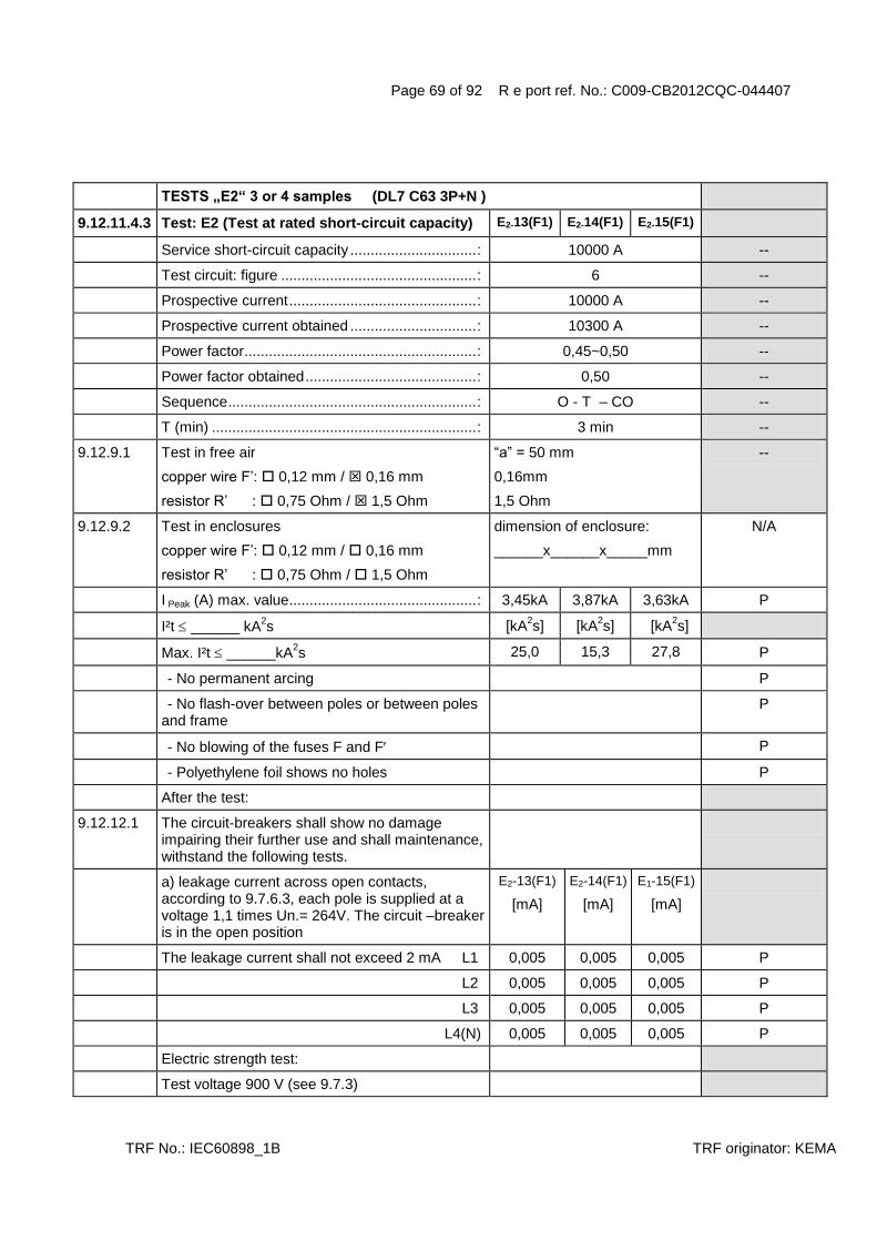
Page 69 of 92 R e port ref. No.: C009-CB2012CQC-044407
TRF No.: IEC60898_1B TRF originator: KEMA
TESTS „E2“ 3 or 4 samples (DL7 C63 3P+N )
9.12.11.4.3 Test: E2 (Test at rated short-circuit capacity) E2-13(F1) E2-14(F1) E2-15(F1)
Service short-circuit capacity ............................... : 10000 A --
Test circuit: figure ................................................ : 6 --
Prospective current .............................................. : 10000 A --
Prospective current obtained ............................... : 10300 A --
Power factor ......................................................... : 0,45~0,50 --
Power factor obtained .......................................... : 0,50 --
Sequence ............................................................. : O - T – CO --
T (min) ................................................................. : 3 min --
9.12.9.1 Test in free air
copper wire F‟: 0,12 mm / 0,16 mm
resistor R‟ : 0,75 Ohm / 1,5 Ohm
“a” = 50 mm
0,16mm
1,5 Ohm
--
9.12.9.2 Test in enclosures
copper wire F‟: 0,12 mm / 0,16 mm
resistor R‟ : 0,75 Ohm / 1,5 Ohm
dimension of enclosure:
______x______x_____mm
N/A
I Peak (A) max. value .............................................. : 3,45kA 3,87kA 3,63kA P
I²t ______ kA2s [kA
2s] [kA
2s] [kA
2s]
Max. I²t ______kA2s 25,0 15,3 27,8 P
- No permanent arcing P
- No flash-over between poles or between poles and frame
P
- No blowing of the fuses F and F P
- Polyethylene foil shows no holes P
After the test:
9.12.12.1 The circuit-breakers shall show no damage impairing their further use and shall maintenance, withstand the following tests.
a) leakage current across open contacts, according to 9.7.6.3, each pole is supplied at a voltage 1,1 times Un.= 264V. The circuit –breaker is in the open position
E2-13(F1)
[mA]
E2-14(F1)
[mA]
E1-15(F1)
[mA]
The leakage current shall not exceed 2 mA L1 0,005 0,005 0,005 P
L2 0,005 0,005 0,005 P
L3 0,005 0,005 0,005 P
L4(N) 0,005 0,005 0,005 P
Electric strength test:
Test voltage 900 V (see 9.7.3)

Page 70 of 92 R e port ref. No.: C009-CB2012CQC-044407
TRF No.: IEC60898_1B TRF originator: KEMA
a) P
b) N/A
c) P
d) N/A
e) 2000 V N/A
Test current 2,8 IN 176 A --
Tripping within > 0,1 s up to [s] [s] [s]
- 60 s N/A
- 120 s 11 15 12 P

Page 71 of 92 R e port ref. No.: C009-CB2012CQC-044407
TRF No.: IEC60898_1B TRF originator: KEMA
6 MARKING AND OTHER INFORMATION (DL7 C63 3P+N)
Circuit-breaker marked with:
a) Manufacturer‟s name or trade mark ................ : DENROM P
b)Type designation, catalogue number or other identification number ........................................ :
DL7-63/3N/C P
c) Rated voltage (V) ............................................. : 415 P
d) Rated current (A) ............................................. : 63 P
e) Rated frequency (Hz) ....................................... : N/A
f) Rated short circuit capacity (A) ........................ : 10000 P
g) Wiring diagram P
h) Ambient air temperature, if different from
30°C
N/A
i) Degree of protection, if different from IP20 N/A
j) For D-type circuit-breakers: the maximum instantaneous tripping current, if higher than 20 In(see table 2)
N/A
k) Rated impulse withstand voltage Uimp if it is 2,5 kV
N/A
Symbol for instantaneous tripping current C P
Symbol for nature of supply N/A
Marking for rated current and for instantaneous tripping shall be readily visible when CB is installed
P
Other marking shall be easily discernible P
The suitability for isolation, which is provided by all circuit-breakers of this standard, may be indicated by the symbol on the device
P
Energy limiting class N/A
I2t characteristic (documentation) N/A
Symbols on supply and load terminal P
Terminal for neutral conductor N N/A
Earthing terminal if any (IEC 60417-5019) N/A
On – off position shall be clearly indicated – 0 I - P
For push-button CB the off push-button shall either be red or be marked with the symbol 0́ ́
N/A
Red not used for other push-button N/A
This symbol shall be easily discernible N/A
For CB with multiple current ratings, the maximum value is marked, the adjusted value indicated without ambiguity
N/A

Page 72 of 92 R e port ref. No.: C009-CB2012CQC-044407
TRF No.: IEC60898_1B TRF originator: KEMA
Marking shall be indelible and easily legible (not on removable parts), 15 s with water, 15 s with hexane (see cl. 8.3)
P
8. REQUIREMENTS FOR CONSTRUCTION AND OPERATION (DL7 C63 3P+N)
8.1.1 General
8.1.2 Mechanism
The moving contact shall be mechanically coupled so that all poles make and break together, whether operated manually or automatically, even if an overload occurs on one pole only
N/A
The switched neutral shall close before and open after the protected pole (s)
N/A
Neutral pole having adequate making and breaking capacity and CB with independent manual operation: all poles operate together including neutral pole
N/A
CB shall have a trip free mechanism P
It shall be possible to switch the CB on and off by hand
P
No intermediate position of the contacts P
Position of contacts shall be indicated P
Indication visible from the outside P
If the indication is on the actuating means, it shall, when released, automatically take up or stay in the position corresponding to that of the moving contacts; operating means shall have two different rest positions, except that, for automatic operation, a third distinct rest position may be provided
P
If a separate mechanical indicator is used to indicate the position of the main contacts, colour red shall be used for the on position and green for the off position.
P
The action of the mechanism shall not be influenced by the position of enclosures
P
If the cover is used as a guiding means for push-button, it shall not be possible to remove this button from the outside
N/A
Operating means securely fixed, not possible to remove them without a tool
P
For the up-down operating means the contacts shall be closed by the up movement.
P

Page 73 of 92 R e port ref. No.: C009-CB2012CQC-044407
TRF No.: IEC60898_1B TRF originator: KEMA
8.1.3 Clearances and creepage distances
8.1.3 Clearances [mm] see table 4
1.between live parts (of the main circuits) which are separated when the CB is in off position ....... :
N/A
2.between live parts of different polarity .............. : 9,6mm P
3.between circuits supplied from different sources, one of which being PELV or SELV........ :
N/A
4. between live parts and
- accessible surfaces of operating means ........... : 9,8mm P
- screws or other means for fixing covers ............ : N/A
- surface on which the base is mounted .............. : 14,1mm P
- screws or other means for fixing the circuit breaker .............................................................. :
N/A
- metal covers or boxes ....................................... : N/A
- other accessible metal parts .............................. : 8,2mm P
- metal frames supporting the base (flush-type) .. : N/A
5.between metal parts of mechanism and:
- accessible metal parts ....................................... : N/A
- screws or other means for fixing the circuit breaker .............................................................. :
N/A
- metal frames supporting the base (flush type) .. : N/A
8.1.3 Creepage distances [mm] (see table 4)
Material group IIIa
II
I
--
1.between live parts (of the main circuits) which are separated when the CB is in off position ....... :
N/A
2.between live parts of different polarity .............. : 5,2mm P
3.between circuits supplied from different sources, one of which being PELV or SELV........ :
N/A
4. between live parts and
- accessible surfaces of operating means ........... : 10,4mm P
- screws or other means for fixing covers ............ : N/A
- surface on which the base is mounted .............. : N/A
- screws or other means for fixing the circuit breaker .............................................................. :
N/A
- metal covers or boxes ....................................... : N/A
- other accessible metal parts .............................. : N/A
- metal frames supporting the base (flush-type) .. : N/A
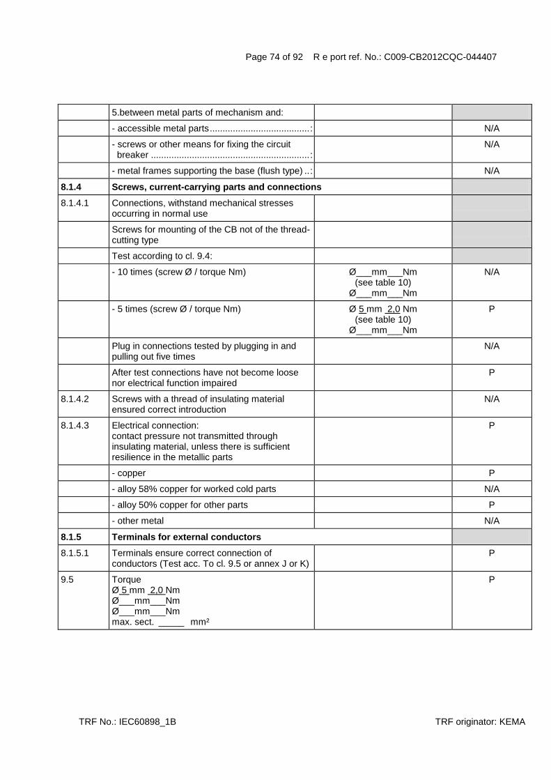
Page 74 of 92 R e port ref. No.: C009-CB2012CQC-044407
TRF No.: IEC60898_1B TRF originator: KEMA
5.between metal parts of mechanism and:
- accessible metal parts ....................................... : N/A
- screws or other means for fixing the circuit breaker .............................................................. :
N/A
- metal frames supporting the base (flush type) .. : N/A
8.1.4 Screws, current-carrying parts and connections
8.1.4.1 Connections, withstand mechanical stresses occurring in normal use
Screws for mounting of the CB not of the thread-cutting type
Test according to cl. 9.4:
- 10 times (screw Ø / torque Nm) Ø___mm___Nm (see table 10)
Ø___mm___Nm
N/A
- 5 times (screw Ø / torque Nm) Ø 5 mm 2,0 Nm (see table 10)
Ø___mm___Nm
P
Plug in connections tested by plugging in and pulling out five times
N/A
After test connections have not become loose nor electrical function impaired
P
8.1.4.2 Screws with a thread of insulating material ensured correct introduction
N/A
8.1.4.3 Electrical connection: contact pressure not transmitted through insulating material, unless there is sufficient resilience in the metallic parts
P
- copper P
- alloy 58% copper for worked cold parts N/A
- alloy 50% copper for other parts P
- other metal N/A
8.1.5 Terminals for external conductors
8.1.5.1 Terminals ensure correct connection of conductors (Test acc. To cl. 9.5 or annex J or K)
P
9.5 Torque Ø 5 mm 2,0 Nm Ø___mm___Nm Ø___mm___Nm max. sect. _____ mm²
P

Page 75 of 92 R e port ref. No.: C009-CB2012CQC-044407
TRF No.: IEC60898_1B TRF originator: KEMA
9.5.1 Pull test: min sect. ___ 1 mm²
max sect. __ 25 mm² Pull ______ 100 N for 1 min During the test conductor does not move noticeably
P
9.5.2 min sect. ____ 1 __ mm² Torque (2/3)= _ 1,33 Nm max sect. ____ 25 mm
2
The conductor shows no damage
P
9.5.3 Nominal cross-section from ____ 1 to 25 ___ mm² No of wires _____ 7 Ø of wires _____ 2,14 mm Torque (2/3) = ____ 1,33Nm After the test no wire escaped outside
P
8.1.5.2 Terminals allow the connection of conductors of the following cross-sectional areas: (table 5)
Rated current Range of nominal cross (A) sections to be clamped (mm²)
13 1 to 2,5
> 13 16 1 to 4
> 16 25 1,5 to 6
> 25 32 2,5 to 10
> 32 50 4 to 16
> 50 80 10 to 25
> 80 100 16 to 35
> 100 125 25 to 50
It is required that, for current ratings up to and including 50 A terminals are designed to clamp solid conductors as well as rigid stranded conductors; the use of flexible conductors is permitted
P
Nevertheless, it is permitted that terminals for conductors having cross-sections from 1 mm
2
up to 6 mm2 are designed to clamp solid
conductors only.
1 to 25 mm² P
8.1.5.3 Means for clamping the conductors in the terminals not serve to fix any other component (See test sub-clause 9.5)
P
8.1.5.4 Terminals for IN 32 A allow the connection of conductors without special preparation
P
8.1.5.5 Terminals shall have adequate mechanical strength; ISO thread or equivalent (See tests of sub-clause 9.4 and 9.5.1)
P

Page 76 of 92 R e port ref. No.: C009-CB2012CQC-044407
TRF No.: IEC60898_1B TRF originator: KEMA
8.1.5.6 Clamping of conductor without damage to the conductor (See test of sub-clause 9.5.2)
P
8.1.5.7 Clamping of conductor between metal surfaces (See tests of sub-clause 9.4 and 9.5.1)
P
8.1.5.8 Conductor shall not slip-out when the clamping screw or nuts are tightened (See test of sub-clause 9.5.3)
P
8.1.5.9 Terminals shall be properly fixed. No work loose when the clamping screws or nuts are tightened or loosened (See test of sub-clause 9.4)
P
8.1.5.10 Clamping screws or nuts of terminals for protective conductors adequately secured against accidental loosening
N/A
8.1.5.11 Screws and nuts of terminals for external conductors shall be in engagement with a metal thread, and the screws shall not be of tapping screw type
P
8.1.6 Non interchangeability
For circuit-breakers intended to be mounted on bases forming a unit therewith(plug-in or screw-in type) it shall not be possible, without the aid of a tool, to replace a circuit-breaker when mounted as for normal use by another of the same make having a higher rated current, compliance is checked by inspection
N/A
8.1.7 Plug-in type circuit-breakers, the holding in position of which does not depend solely on their plug-in connection(s), shall be reliable and have adequate stability
N/A
8.1.7.1 Plug-in type circuit-breakers, the holding in position of which does not depend solely on their plug-in connection(s)
Compliance of the mechanical mounting is checked by the relevant test 9.13
N/A
8.1.7.2 Plug-in type circuit-breakers, the holding in position of which does depend solely on their plug-in connection(s)
Compliance of the mechanical mounting is checked by the relevant test 9.13
N/A
8.2 Protection against electric shock
Live parts not accessible in normal use P
For CB, other than plug-in type, external parts, other than screws and other means for fixing covers, which are accessible shall be of insulating material
P

Page 77 of 92 R e port ref. No.: C009-CB2012CQC-044407
TRF No.: IEC60898_1B TRF originator: KEMA
Unless the live parts are within an internal enclosure of insulating material: Lining - reliable fixed, - adequate thickness and - mechanical strength
N/A
Inlet openings for cables shall be in insulating material or be provided with bushings or similar devices in insulating material Such device - shall be reliable fixed - shall have adequate mechanical strength
N/A
For plug-in CB, external parts, other than screws and other means for fixing covers, which are accessible shall be in insulating material
N/A
Metallic operating means insulated from live parts
N/A
Metal parts of the mechanism not accessible and insulated from accessible metal parts, metal frames (for flush-type), screws or other means for fixing the base
P
Replacement of plug-in CB possible without touching live parts
N/A
Lacquer or enamel not considered N/A
9.6 Test of protection against electric shock
Use of test finger so designed that each jointed can be turned through an angle of 90° with respect to the finger
P
Circuit-breaker with enclosures of thermoplastic material are additional tested at 35 °C for 1 min with a force of 75 N
P
8.10 Resistance to heat
CB sufficiently resistant to heat P
9.14 Test of resistance to heat
9.14.1 Test:
- without removable covers ....... 1 h (100 2) °C P
- removable covers ...................... 1 h (70 2) °C N/A
After the test no access to live parts, marking still legible
P
9.14.2 Ball pressure test for external parts of insulating material (parts retaining current-carrying parts and parts of the protective circuit in position) T = 125°C
Ø of impression 2 mm
Impression: 1.2 mm P

Page 78 of 92 R e port ref. No.: C009-CB2012CQC-044407
TRF No.: IEC60898_1B TRF originator: KEMA
9.14.3 Ball pressure test for external parts of insulating material (parts not retaining current-carrying parts and parts of the protective circuit in position
T = (70 2)°C or
T = ___ °C = (40 2)°C + max. temperature rise of sub-clause 8.8
Ø of impression 2 mm
N/A
8.11 Resistance to abnormal heat and to fire
External parts of insulating material shall not ignite or spread fire under fault or overload conditions
P
9.15 Resistance to abnormal heat and to fire
Glow wire test: No visible flame, no sustained glowing or flames and glowing extinguish within 30 s
P
external parts retaining current-carrying parts and parts of the protective circuit
in position ....................................... (960 15)°C
P
all other external parts .................... (650 10)°C N/A
8.12 Resistance to rusting
Ferrous parts adequately protected against rusting
P
9.16 Test of resistance to rusting:
- 10 min immersed in a cold chemical degreaser such as methyl-chloroform or refined petrol
P
- 10 min immersed in a 10% solution of ammonium chloride in water at 20°C
P
- 10 min at 95% humidity at 20°C P
- 10 min at 100°C P
No sign of rust P
TESTS „B“ 3 samples (DL7 C63 3P+N) B-4 B-5 B-6
8.3 Dielectric properties and isolating capability
CB shall have adequate dielectric properties and shall ensure isolation:
P
8.3.1 Dielectric strength at power frequency P
Compliance is checked by the tests 9.7.1, 9.7.2 and 9.7.3 on circuit-breaker in new condition
P
8.3.2 Isolating capability P
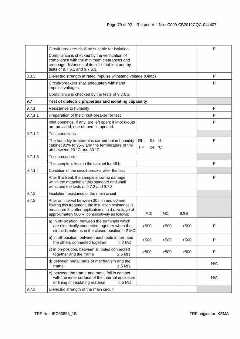
Page 79 of 92 R e port ref. No.: C009-CB2012CQC-044407
TRF No.: IEC60898_1B TRF originator: KEMA
Circuit-breakers shall be suitable for isolation.
Compliance is checked by the verification of compliance with the minimum clearances and creepage distances of item 1 of table 4 and by tests of 9.7.6.1 and 9.7.6.3.
P
8.3.3 Dielectric strength at rated impulse withstand voltage (Uimp) P
Circuit-breakers shall adequately withstand impulse voltages.
Compliance is checked by the tests of 9.7.6.2.
P
9.7 Test of dielectric properties and isolating capability
9.7.1 Resistance to humidity P
9.7.1.1 Preparation of the circuit-breaker for test P
Inlet openings, if any, are left open; if knock-outs are provided, one of them is opened.
P
9.7.1.2 Test conditions
The humidity treatment is carried out in humidity cabinet 91% to 95% and the temperature of the air between 20 °C and 30 °C
Rf = 93 %
T = 24 °C
P
9.7.1.3 Test procedure:
The sample is kept in the cabinet for 48 h. P
9.7.1.4 Condition of the circuit-breaker after the test
After this treat, the sample show no damage within the meaning of this standard and shall withstand the tests of 9.7.2 and 9.7.3
P
9.7.2 Insulation resistance of the main circuit
9.7.2 After an interval between 30 min and 60 min flowing this treatment, the insulation resistance is measured 5 s after application of a d.c. voltage of approximately 500 V, consecutively as follows:
[MΩ] [MΩ] [MΩ]
a) In off-position, between the terminals which are electrically connected together when the
circuit-breaker is in the closed position 2 M
>500 >500 >500 P
b) in off-position, between each pole in turn and
the others connected together 2 M >500 >500 >500 P
c) in on-position, between all poles connected
together and the frame 5 M >500 >500 >500 P
d) between metal parts of mechanism and the
frame 5 M N/A
e) between the frame and metal foil in contact with the inner surface of the internal enclosure
or lining of insulating material 5 M
N/A
9.7.3 Dielectric strength of the main circuit

Page 80 of 92 R e port ref. No.: C009-CB2012CQC-044407
TRF No.: IEC60898_1B TRF originator: KEMA
After the circuit-breakers have passed the tests of 9.7.2 the test voltage specified in 9.7.5 is applied for 1 min between the parts indicated in 9.7.2
a) 2000 V P
b) 2000 V P
c) 2000 V P
d) 2000 V N/A
e) 2500 V N/A
9.7.4 Dielectric strength of the auxiliary and control circuits
For these tests, the main circuit shall be connected to the frame. The test voltage specified in 9.7.5 shall be applied for 1 min as follows:
1) Between all the auxiliary or control circuits and the frame U = ____ V
U = ____ V N/A
2) Between each part of the auxiliary or control circuits which may be isolated from the other parts of the auxiliary or control circuits and these other parts connected together
U = [1000 V if Ui 60 V or 2Ui + 1000 V if Ui > 60 V]
U = ____ V N/A
9.7.6 Verification of the impulse withstand voltage (across clearances and across solid insulation) and leakage current across open contacts
9.7.6.1 Verification of the impulse withstand voltage across open contacts (suitability for isolation)
The 1,2/50µs impulse voltage shall be applied three times for each polarity at intervals of 1s minimum
- rated impulse withstand voltage (kV) : 4kV --
- sea level of the laboratory: 12m --
- test Uimp on open main contacts (equipment suitable for isolating) (see table 13 .......................... :
Utest = 6,2 kV
--
- no unintentional disruptive discharge during the test‟s
P
9.7.6.2 Verification of impulse withstand voltage for the parts not test in 9.7.6.1
The 1,2/50µs impulse voltage shall be applied three times for each polarity at intervals of 1s minimum
- rated impulse withstand voltage (kV) : 4kV --
- sea level of the laboratory: 12m --
- test Uimp main circuits (see table 14) : Utest = 4,9 kV --
Application of test voltage
i) Between all the phase pole(s) connected together and to the neutral pole (or path) of the circuit-breaker
P
ii) Between all the phase pole(s) and the neutral pole(or path) connected together and the metal support connected to the terminals intended for the protective conductor(s)
P

Page 81 of 92 R e port ref. No.: C009-CB2012CQC-044407
TRF No.: IEC60898_1B TRF originator: KEMA
- no unintentional disruptive discharge during the test‟s
P
9.7.6.3 Verification of leakage currents across open contacts(suitability for isolation)
For circuit-breakers suitable for isolation, the leakage current shall be measured. Each pole having been submitted to the test of 9.12.11.2, or 9.12.11.3, or 9.12.11.4.2 or 9.12.11.4.3 is supplied at a test voltage of 1,1 times its rated operational voltage, the circuit-breaker being in the open position
457V --
The leakage current flowing across the open contacts is measured and shall not exceed 2 mA
<0,03 <0,03 <0,03 P
8.4 Temperature rise
Temperature rise does not exceed the limiting values stated in table V:
sect. 16 mm² --
9.8.2 Test current: IN= (reach the steady-state value)
Four-pole CB„s: 1) three poles loaded
2) one pole and neutral pole loaded
IN = 63A
--
Ambient air temperature ...................................... : Tamb= 22 ℃ --
Parts .................................... Temperature rise [K] [K] [K] [K]
L1
L2
L3
L4(N)
L3
N
______________________ ______________________ ______________________ ______________________ ______________________ _____________________
P
Terminals for external connections .................. 60 37~44 37~44 38~46 P
External parts liable to be touched during manual operation of the circuit-breaker, including operating means of insulating material and metallic means for coupling of insulating operating means of several poles ..................... 40
P
18 16 21
External metallic parts of operating means ...... 25 ______________________ N/A
Other external parts, including that face of the circuit-breaker is in direct contact with the mounting surface .............................................. 60
36 36 37
P
9.8.5 Measurement of power losses B-4 B-5 B-6
Power loss do not exceed the values stated in table 15
B-4 B-5 B-6

Page 82 of 92 R e port ref. No.: C009-CB2012CQC-044407
TRF No.: IEC60898_1B TRF originator: KEMA
Test current: IN = 63 A (reach the steady state value)
Loaded one pole after the other W W W
L1
L2
L3
L4(N)
L3
N
Max power loss: 13 W 6,99 6,68 7,31 6,80 6,55 6,68 7,24 6,62 7,37 7,18 6,80 7,18 ______________________ ______________________
P
8.5 Uninterrupted duty
Circuit-breakers operate reliable even after long service
P
9.9 28 day test
28 cycles - 21 h with current - 3 h without current
cross sectional area. 16 mm²
IN = 63 A --
During the test no tripping during the last period, temperature rise shall be measured
P
Ambient air temperature ...................................... : 23 ° C --
Parts .................................... Temperature rise [K] [K] [K] [K]
Terminals for external connections .................. 60 N/A
The temperature rise does not exceed the value measured during the temperature rise test (subclause 8.8) by more than 15 K
32~45 38~46 39~45 P
Test current 1,45 IN = 63A 91,4 A --
- Tripping within [s] [s] [s]
- 1h ( 63 A) 2min19s 1min56s 3min19s P
- 2h (> 63 A) N/A
TESTS „C“ 3 samples (DL7 C63 3P+N) C1-4 C1-5 C1-6
8.7 Mechanical and electrical endurance
Circuit-breaker shall be capable to perform an adequate number of cycles with rated current
P
9.11.1 General test conditions

Page 83 of 92 R e port ref. No.: C009-CB2012CQC-044407
TRF No.: IEC60898_1B TRF originator: KEMA
Test: Test Voltage 415 V (rated voltage) Test Current 63 A (rated current)
Power factor ________(0.85-0,90)
Par. Resistor _________ Ohm Cross sect. area 16mm²
416V
63,3A
0,86
--
9.11.2 Test procedure
The circuit-breaker is submitted to 4000 operating cycles with rated current.
P
- IN 32 A: 2 s on – 13 s off N/A
- IN 32 A: 2 s on – 28 s off P
During the test the circuit-breaker shall be operated as in normal use.
P
9.11.3 Condition of the circuit-breaker after the test
Following the test 9.11.2 the sample shall not show:
- undue wear P
- discrepancy between the position of the moving contacts and corresponding position of the Indicating device
P
- damage to the enclosure permitting access to live parts by test finger (see 9.6)
P
- loosening of electrical or mechanical connections
P
- seepage of sealing compound P
Moreover test current ................................. 2,55 IN 161A --
Opening time not less 1 s or more than [s] [s] [s]
- 60 s ( 32 A) N/A
- 120 s ( 32 A) 26 24 24 P
Dielectric strength reduced to 900 V (1500 V acc. IEC 60898)
P
9.12.11.2 Test at reduced short-circuit currents
9.12.11.2.1 Test on all circuit-breakers
9.12.11.2.1 Test at reduced short-circuit currents: Fig. 3
Test current: Obtained
- 500 A or 10 In I test= 634A --
Test voltage 1,05 Un U = 240V --
Power factor 0,93-0,98 0,98 --
9.12.9.1 Test in free air
copper wire F‟: 0,12 mm / 0,16 mm
resistor R‟ : 0,75 Ohm / 1,5 Ohm
“a” = 35 mm
0,16mm
1,5 Ohm
--

Page 84 of 92 R e port ref. No.: C009-CB2012CQC-044407
TRF No.: IEC60898_1B TRF originator: KEMA
9.12.9.2 Test in enclosures
copper wire F‟: 0,12 mm / 0,16 mm
resistor R‟ : 0,75 Ohm / 1,5 Ohm
dimension of enclosure:
______x______x_____mm
N/A
I Peak (A) max. value 882A 863A 867A P
Sequence: 6 x ”0” and 3 x “CO” [kA2s] [kA
2s] [kA
2s]
Max. I²t ______kA2s 6,88 4,07 3,58 P
- No permanent arcing P
- No flash-over between poles or between poles and frame
P
- No blowing of the fuses F and F P
- Polyethylene foil shows no holes P
After the test:
9.12.12 Verification of the circuit-breaker after short-circuit tests
9.12.12.1 The circuit-breakers shall show no damage impairing their further use and shall maintenance, withstand the following tests.
a) leakage current across open contacts, according to 9.7.6.3, each pole is supplied at a voltage 1,1 times Un.= 456 V. The circuit –breaker is in the open position
C1-4
(mA)
C1-5
(mA)
C1-6
(mA)
The leakage current shall not exceed 2 mA L1
<0,01 <0,01 <0,01 P
L2
<0,01 <0,01 <0,01 P
L3
<0,01 <0,01 <0,01 P
L4(N) <0,01 <0,01 <0,01 P
Electric strength test:
Test voltage 1500 V (see 8.7.2)
a) P
b) P
c) P
d) N/A
e) 2000 V N/A
9.12.11.2.
2
Short-circuit test on circuit-breakers rated 230 V, or 240 V or 230/400 V for
verifying for use in IT systems (DL7 C63 3P+N)
Test current: Obtained

Page 85 of 92 R e port ref. No.: C009-CB2012CQC-044407
TRF No.: IEC60898_1B TRF originator: KEMA
- 500 A or 1,2 times the upper limit of the standard range of instantaneous tripping (see table 2 ) whichever is the higher, but < 2500 A. When Itripping exceed 20 In the current adjusted at 1,2 times the upper limit even when higher 2500 A
I test= 766A --
Test voltage 1,05 Un U = 436V --
Power factor 0,93-0,98 0,95 --
9.12.9.1 Test in free air
copper wire F‟: 0,12 mm / 0,16 mm
resistor R‟ : 0,75 Ohm / 1,5 Ohm
“a” = 35 mm
0,16mm
1,5 Ohm
--
9.12.9.2 Test in enclosures
copper wire F‟: 0,12 mm / 0,16 mm
resistor R‟ : 0,75 Ohm / 1,5 Ohm
dimension of enclosure:
______x______x_____mm
N/A
I Peak (A) max. value 987A 1010A 1000A P
Sequence: ”0” + “CO” on each protected pole [kA2s] [kA
2s] [kA
2s]
Shifted point 30 ° on the other protected pole C2-6 L1 C2-6 L2 C2-6 L3
Max. I²t ______kA2s 3,85 4,08 3,73 P
- No permanent arcing P
- No flash-over between poles or between poles and frame
P
- No blowing of the fuses F and F P
- Polyethylene foil shows no holes P
After the test:
9.12.12.1 The circuit-breakers shall show no damage impairing their further use and
shall maintenance, withstand the following tests.
a) leakage current across open contacts, according to 9.7.6.3, each pole is supplied at a voltage 1,1 times Un.= 456 V. The circuit –breaker is in the open position
C2-6
[mA]
The leakage current shall not exceed 2 mA L1 <0,01 P
L2 <0,01 P
L3 <0,01 P
L4(N) <0,01 P
Electric strength test:
Test voltage 1500 V (see 8.7.2)
a) P
b) P
c) P
d) N/A

Page 86 of 92 R e port ref. No.: C009-CB2012CQC-044407
TRF No.: IEC60898_1B TRF originator: KEMA
e) 2000 V N/A
TESTS „D“ 3 samples (DL7 C63 3P+N)
8.6 Automatic operation
8.6.1 Standard time-current zone
Tripping characteristic of CB ensures adequate protection of the circuit, without premature operation.
9.10 Tests: D0 D-4(F01) D-5(F01) D-6(F01)
IN (A) 63
Sect. (mm²) 16
Instantaneous tripping current B C D
9.10.1 Test of time-current characteristic
9.10.1.1 Test current 1,13 IN (A) starting from cold for: 71,2 A --
- 1 h (IN 63 A) >1 >1 >1 P
- 2 h (IN 63 A) N/A
No tripping
Then steadily increased within 5 s to 1,45 IN (A) 91,4A --
- Tripping within [min] [min] [min]
- 1h ( 63 A) 1min03s 59s 47s P
- 2h (> 63 A) N/A
9.10.1.2 Test current 2,55 IN (A) starting from cold for: 160 A --
opening time not less than 1 s or more than [s] [s] [s]
- 60 s N/A
- 120 s 34 32 35 P
9.10.2 Teast of instantaneous tripping and of correct opening of the contacts
9.10.2.1 General test conditions
For the lower values of the test current the test is made once, at any convenient voltage.
For the upper values of the test current the test is made at rated voltage Un( phase to neutral) with a power factor between 0,95 and 1.
420V
0,98
--
The sequence of operation is : O-CO-CO-CO
Interval time: > 3 min
The tripping time of the O operation is measured
After each operation the indicating means shall show the open position of the contacts
P
9.10.2.2 For circuit-breakers of the B – Type
Test current 3IN (A), starting from cold

Page 87 of 92 R e port ref. No.: C009-CB2012CQC-044407
TRF No.: IEC60898_1B TRF originator: KEMA
Opening time: [s] [s] [s]
- 0,1s t 45s ( 32A) N/A
- 0,1s t 90s ( 32A) N/A
Test current 5 IN (A), starting from cold N/A
Tripping less than 0,1 s N/A
9.10.2.3 For circuit-breakers of the C – Type
Test current 5IN (A), starting from cold 315A --
Opening time: [s] [s] [s]
- 0,1s t 15s ( 32A) N/A
- 0,1s t 30s ( 32A) 14 13 14 P
Test current 10 IN (A), starting from cold 635A --
Tripping less than 0,1 s 8,75ms 13,4ms 8,64ms P
9.10.2.4 For circuit-breakers of the D – Type
Test current 10IN (A), starting from cold
Opening time: [s] [s] [s]
- 0,1s t 4s ( 32A) N/A
- 0,1s t 8s ( 32A) N/A
Test current 20 IN (A) or to the maximum instantaneous tripping current(see cl. 6, item j), starting from cold
N/A
Tripping less than 0,1 s N/A
9.10.3 Test of effect of single pole loading on the tripping characteristic of multipole circuit-breakers:
Test current 1,1 It (A), (two pole) starting from cold
Tripping within [min] [min] [min]
- 1h N/A
- 2h N/A
Test current 1,2 It (A), (three pole or four pole) starting from cold
110A --
Tripping within [min] [min] [min]
- 1h 3min34s 4min25s 6min09s P
- 2h N/A
9.10.4 Test of effect of ambient temperature on the tripping characteristics
a) Ambient temperature of (-5 2)°C below the ambient air reference temperature
T = -5°C --
Test current 1,13 IN (A) 71,2A --
- Passed for 1h >1h >1h >1h P

Page 88 of 92 R e port ref. No.: C009-CB2012CQC-044407
TRF No.: IEC60898_1B TRF originator: KEMA
- Passed for 2h N/A
Current is then steadily increased to 1,9 IN (A) within 5s
120A --
Tripping within [min] [min] [min]
- 1h 1min26s 2min45s 4min07s P
- 2h N/A
b) Ambient temperature of (40 2)°C T = 40°C --
Test current IN (A) 63,0A --
No tripping within
- 1h >1h >1h >1h P
- 2h N/A
Tests: D1 (DL7 C63 3P+N) D-4(F01) D-5(F01) D-6(F01)
8.9 Resistance to mechanical shock and impact
CB shall have adequate mechanical behaviour so as to withstand the stresses imposed during installation and use
P
9.13.1 Mechanical shock
- 50 falls on two sides of vertical board C P
- Vertical board turned 90° P
- 50 falls on two sides of vertical board C P
During the test the circuit-breakers shall not open
P
9.13.2 Mechanical impact
9.13.2.1 All types:
- Impact test: 10 blows-height 10 cm, no damage
P
9.13.2.2 Screw-in types:
- Torque 2,5 Nm for 1 min, no damage P
9.13.2.3 CB intended to be mounted on a rail
- downward vertical 50 N for 1 min P
- upward vertical 50 N for 1 min, no damage P
9.13.2.4 Plug-in types
The circuit-breaker are mounted in there normal position, complete with plug-in base but without cables and any cover plate
N/A
A force of 20 N applied for 1min to the circuit-breaker (see fig 17).
N/A
During this test the circuit-breaker part shall not become loose from the base and shall not show damage impairing further use.
N/A

Page 89 of 92 R e port ref. No.: C009-CB2012CQC-044407
TRF No.: IEC60898_1B TRF originator: KEMA
9.12.11.3 Test at 1500 A:
Prospective current of 1500 A – power factor 0,93 to 0,98
Prospective current obtained (A) 1560 A --
Power factor 0,97 --
Test voltage 1,05 Un 436V --
Test circuit: figure 5 --
T (min) 3 min --
9.12.9.1 Test in free air
copper wire F‟: 0,12 mm / 0,16 mm
resistor R‟ : 0,75 Ohm / 1,5 Ohm
“a” = 35 mm
0,16mm
1,5 Ohm
--
9.12.9.2 Test in enclosures
copper wire F‟: 0,12 mm / 0,16 mm
resistor R‟ : 0,75 Ohm / 1,5 Ohm
dimension of enclosure:
______x______x_____mm
N/A
Sequence 6 x O - 3 x CO
I Peak (A) max. value 1,78kA 1,77kA 1,73kA P
I²t ______ kA2s [kA
2s] [kA
2s] [kA
2s]
Max. I²t ______kA2s 9,96 9,78 8,92 P
- No permanent arcing P
- No flash-over between poles or between poles and frame
P
- No blowing of the fuses F and F P
- Polyethylene foil shows no holes P
After the test:
9.12.12.1 The circuit-breakers shall show no damage impairing their further use and shall maintenance, withstand the following tests.
P
a) leakage current across open contacts, according to 9.7.6.3, each pole is supplied at a voltage 1,1 times Un.=456V. The circuit –breaker is in the open position
D-4(F01)
[mA]
D-5(F01)
[mA]
D-6(F01)
[mA]
The leakage current shall not exceed 2 mA L1 <0,01 <0,01 <0,01 P
L2 <0,01 <0,01 <0,01 P
L3 <0,01 <0,01 <0,01 P
L4(N) <0,01 <0,01 <0,01 P
Electric strength test:
Test voltage 1500 V (see 8.7.2)
a) P
b) P

Page 90 of 92 R e port ref. No.: C009-CB2012CQC-044407
TRF No.: IEC60898_1B TRF originator: KEMA
c) P
d) N/A
e) 2000 V N/A
Test current 0.85x non tripping current (1,13 IN ) 60,5A --
- Passed for 1h > 1h > 1h > 1h P
- Passed for 2h N/A
Current is then steadily increased to 1,1 x tripping current (1,45 IN ) within 5s
100A --
D-4(F01)
[min]
D-5(F01)
[min]
D-6(F01)
[min]
Tripping within 1 hour / 2 hour 16s 20s 17s P

Page 91 of 92 R e port ref. No.: C009-CB2012CQC-044407
TRF No.: IEC60898_1B TRF originator: KEMA
TESTS „E2“ 3 or 4 samples (DL7 C6 3P+N )
9.12.11.4.3 Test: E2 (Test at rated short-circuit capacity) E2-16 E2-17 E2-18
Service short-circuit capacity ............................... : 10000 A --
Test circuit: figure ................................................ : 6 --
Prospective current .............................................. : 10000 A --
Prospective current obtained ............................... : 10300 A --
Power factor ......................................................... : 0,45~0,50 --
Power factor obtained .......................................... : 0,50 --
Sequence ............................................................. : O - T – CO --
T (min) ................................................................. : 3 min --
9.12.9.1 Test in free air
copper wire F‟: 0,12 mm / 0,16 mm
resistor R‟ : 0,75 Ohm / 1,5 Ohm
“a” = 50 mm
0,16mm
1,5 Ohm
--
9.12.9.2 Test in enclosures
copper wire F‟: 0,12 mm / 0,16 mm
resistor R‟ : 0,75 Ohm / 1,5 Ohm
dimension of enclosure:
______x______x_____mm
N/A
I Peak (A) max. value .............................................. : 2,63kA 3,92kA 2,47kA P
I²t ______ kA2s [kA
2s] [kA
2s] [kA
2s]
Max. I²t ______kA2s 20,4 17,9 13,9 P
- No permanent arcing P
- No flash-over between poles or between poles and frame
P
- No blowing of the fuses F and F P
- Polyethylene foil shows no holes P
After the test:
9.12.12.1 The circuit-breakers shall show no damage impairing their further use and shall maintenance, withstand the following tests.
a) leakage current across open contacts, according to 9.7.6.3, each pole is supplied at a voltage 1,1 times Un.= 264V. The circuit –breaker is in the open position
E2-10 [mA]
E2-11 [mA]
E2-12 [mA]
The leakage current shall not exceed 2 mA L1 0,005 0,005 0,005 P
L2 0,005 0,005 0,005 P
L3 0,005 0,005 0,005 P
L4(N) 0,005 0,005 0,005 P
Electric strength test:
Test voltage 900 V (see 9.7.3)

Page 92 of 92 R e port ref. No.: C009-CB2012CQC-044407
TRF No.: IEC60898_1B TRF originator: KEMA
a) P
b) N/A
c) P
d) N/A
e) 2000 V N/A
Test current 2,8 IN 16,8A --
Tripping within > 0,1 s up to [s] [s] [s]
- 60 s 19 17 18 P
- 120 s N/A